JP2010515192A - Multi-touch input discrimination - Google Patents
Multi-touch input discriminationDownload PDFInfo
- Publication number
- JP2010515192A JP2010515192AJP2009544844AJP2009544844AJP2010515192AJP 2010515192 AJP2010515192 AJP 2010515192AJP 2009544844 AJP2009544844 AJP 2009544844AJP 2009544844 AJP2009544844 AJP 2009544844AJP 2010515192 AJP2010515192 AJP 2010515192A
- Authority
- JP
- Japan
- Prior art keywords
- patch
- touch surface
- touch
- surface device
- specified threshold
- Prior art date
- Legal status (The legal status is an assumption and is not a legal conclusion. Google has not performed a legal analysis and makes no representation as to the accuracy of the status listed.)
- Granted
Links
Images


Classifications
- G—PHYSICS
- G06—COMPUTING OR CALCULATING; COUNTING
- G06F—ELECTRIC DIGITAL DATA PROCESSING
- G06F3/00—Input arrangements for transferring data to be processed into a form capable of being handled by the computer; Output arrangements for transferring data from processing unit to output unit, e.g. interface arrangements
- G06F3/01—Input arrangements or combined input and output arrangements for interaction between user and computer
- G06F3/03—Arrangements for converting the position or the displacement of a member into a coded form
- G06F3/041—Digitisers, e.g. for touch screens or touch pads, characterised by the transducing means
- G06F3/0416—Control or interface arrangements specially adapted for digitisers
- G06F3/0418—Control or interface arrangements specially adapted for digitisers for error correction or compensation, e.g. based on parallax, calibration or alignment
- G06F3/04186—Touch location disambiguation
- G—PHYSICS
- G06—COMPUTING OR CALCULATING; COUNTING
- G06F—ELECTRIC DIGITAL DATA PROCESSING
- G06F3/00—Input arrangements for transferring data to be processed into a form capable of being handled by the computer; Output arrangements for transferring data from processing unit to output unit, e.g. interface arrangements
- G06F3/01—Input arrangements or combined input and output arrangements for interaction between user and computer
- G06F3/03—Arrangements for converting the position or the displacement of a member into a coded form
- G06F3/041—Digitisers, e.g. for touch screens or touch pads, characterised by the transducing means
- G06F3/0416—Control or interface arrangements specially adapted for digitisers
- G06F3/04166—Details of scanning methods, e.g. sampling time, grouping of sub areas or time sharing with display driving
- G—PHYSICS
- G06—COMPUTING OR CALCULATING; COUNTING
- G06F—ELECTRIC DIGITAL DATA PROCESSING
- G06F3/00—Input arrangements for transferring data to be processed into a form capable of being handled by the computer; Output arrangements for transferring data from processing unit to output unit, e.g. interface arrangements
- G06F3/01—Input arrangements or combined input and output arrangements for interaction between user and computer
- G06F3/03—Arrangements for converting the position or the displacement of a member into a coded form
- G06F3/041—Digitisers, e.g. for touch screens or touch pads, characterised by the transducing means
- G06F3/0416—Control or interface arrangements specially adapted for digitisers
- G06F3/0418—Control or interface arrangements specially adapted for digitisers for error correction or compensation, e.g. based on parallax, calibration or alignment
- G06F3/04182—Filtering of noise external to the device and not generated by digitiser components
- G—PHYSICS
- G06—COMPUTING OR CALCULATING; COUNTING
- G06F—ELECTRIC DIGITAL DATA PROCESSING
- G06F3/00—Input arrangements for transferring data to be processed into a form capable of being handled by the computer; Output arrangements for transferring data from processing unit to output unit, e.g. interface arrangements
- G06F3/01—Input arrangements or combined input and output arrangements for interaction between user and computer
- G06F3/03—Arrangements for converting the position or the displacement of a member into a coded form
- G06F3/041—Digitisers, e.g. for touch screens or touch pads, characterised by the transducing means
- G—PHYSICS
- G06—COMPUTING OR CALCULATING; COUNTING
- G06F—ELECTRIC DIGITAL DATA PROCESSING
- G06F3/00—Input arrangements for transferring data to be processed into a form capable of being handled by the computer; Output arrangements for transferring data from processing unit to output unit, e.g. interface arrangements
- G06F3/01—Input arrangements or combined input and output arrangements for interaction between user and computer
- G06F3/03—Arrangements for converting the position or the displacement of a member into a coded form
- G06F3/0304—Detection arrangements using opto-electronic means
- G—PHYSICS
- G06—COMPUTING OR CALCULATING; COUNTING
- G06F—ELECTRIC DIGITAL DATA PROCESSING
- G06F3/00—Input arrangements for transferring data to be processed into a form capable of being handled by the computer; Output arrangements for transferring data from processing unit to output unit, e.g. interface arrangements
- G06F3/01—Input arrangements or combined input and output arrangements for interaction between user and computer
- G06F3/03—Arrangements for converting the position or the displacement of a member into a coded form
- G06F3/041—Digitisers, e.g. for touch screens or touch pads, characterised by the transducing means
- G06F3/0414—Digitisers, e.g. for touch screens or touch pads, characterised by the transducing means using force sensing means to determine a position
- G—PHYSICS
- G06—COMPUTING OR CALCULATING; COUNTING
- G06F—ELECTRIC DIGITAL DATA PROCESSING
- G06F3/00—Input arrangements for transferring data to be processed into a form capable of being handled by the computer; Output arrangements for transferring data from processing unit to output unit, e.g. interface arrangements
- G06F3/01—Input arrangements or combined input and output arrangements for interaction between user and computer
- G06F3/03—Arrangements for converting the position or the displacement of a member into a coded form
- G06F3/041—Digitisers, e.g. for touch screens or touch pads, characterised by the transducing means
- G06F3/0416—Control or interface arrangements specially adapted for digitisers
- G—PHYSICS
- G06—COMPUTING OR CALCULATING; COUNTING
- G06F—ELECTRIC DIGITAL DATA PROCESSING
- G06F3/00—Input arrangements for transferring data to be processed into a form capable of being handled by the computer; Output arrangements for transferring data from processing unit to output unit, e.g. interface arrangements
- G06F3/01—Input arrangements or combined input and output arrangements for interaction between user and computer
- G06F3/03—Arrangements for converting the position or the displacement of a member into a coded form
- G06F3/041—Digitisers, e.g. for touch screens or touch pads, characterised by the transducing means
- G06F3/042—Digitisers, e.g. for touch screens or touch pads, characterised by the transducing means by opto-electronic means
- G—PHYSICS
- G06—COMPUTING OR CALCULATING; COUNTING
- G06F—ELECTRIC DIGITAL DATA PROCESSING
- G06F3/00—Input arrangements for transferring data to be processed into a form capable of being handled by the computer; Output arrangements for transferring data from processing unit to output unit, e.g. interface arrangements
- G06F3/01—Input arrangements or combined input and output arrangements for interaction between user and computer
- G06F3/03—Arrangements for converting the position or the displacement of a member into a coded form
- G06F3/041—Digitisers, e.g. for touch screens or touch pads, characterised by the transducing means
- G06F3/044—Digitisers, e.g. for touch screens or touch pads, characterised by the transducing means by capacitive means
- G—PHYSICS
- G06—COMPUTING OR CALCULATING; COUNTING
- G06V—IMAGE OR VIDEO RECOGNITION OR UNDERSTANDING
- G06V40/00—Recognition of biometric, human-related or animal-related patterns in image or video data
- G06V40/10—Human or animal bodies, e.g. vehicle occupants or pedestrians; Body parts, e.g. hands
- G06V40/107—Static hand or arm
- G—PHYSICS
- G06—COMPUTING OR CALCULATING; COUNTING
- G06F—ELECTRIC DIGITAL DATA PROCESSING
- G06F2203/00—Indexing scheme relating to G06F3/00 - G06F3/048
- G06F2203/041—Indexing scheme relating to G06F3/041 - G06F3/045
- G06F2203/04106—Multi-sensing digitiser, i.e. digitiser using at least two different sensing technologies simultaneously or alternatively, e.g. for detecting pen and finger, for saving power or for improving position detection
Landscapes
- Engineering & Computer Science (AREA)
- Theoretical Computer Science (AREA)
- General Engineering & Computer Science (AREA)
- Human Computer Interaction (AREA)
- Physics & Mathematics (AREA)
- General Physics & Mathematics (AREA)
- Multimedia (AREA)
- Position Input By Displaying (AREA)
- User Interface Of Digital Computer (AREA)
Abstract
Translated fromJapaneseDescription
Translated fromJapanese本発明は、一般的に、電子装置のためのデータ入力方法及び装置に係り、より詳細には、マルチタッチのタッチ表面入力装置への種々の入力間を弁別するための方法及び装置に係る。 The present invention relates generally to a data input method and apparatus for electronic devices, and more particularly to a method and apparatus for discriminating between various inputs to a multi-touch touch surface input device.
現在、電子システムとのオペレーションを遂行するための多数の形式の入力装置が存在する。これらのオペレーションは、ディスプレイスクリーン上でカーソルを移動し及び/又は選択を行うことにしばしば対応する。又、電子システムは、タブレット、ノートブック、デスクストップ、及びサーバーコンピュータシステム、パーソナルデジタルアシスタント、オーディオ及びビデオ制御システム、ポータブル音楽及びビデオプレーヤ、並びに移動及び衛星電話を含む。これら形式の電子システムでは、使い易さ及び操作の多様性のために、タッチパッド及びタッチスクリーンシステム(集合的に「タッチ表面」)の使用が益々普及してきている。 Currently, there are many types of input devices for performing operations with electronic systems. These operations often correspond to moving the cursor and / or making a selection on the display screen. Electronic systems also include tablets, notebooks, desk stops, and server computer systems, personal digital assistants, audio and video control systems, portable music and video players, and mobile and satellite phones. In these types of electronic systems, the use of touchpads and touch screen systems (collectively “touch surfaces”) is becoming increasingly popular due to their ease of use and variety of operations.
1つの特定形式のタッチ表面は、タッチスクリーンである。タッチスクリーンは、典型的に、タッチパネル、コントローラ及びソフトウェアドライバを含む。タッチパネルは、特徴的には、ディスプレイスクリーンの前面にタッチ感知表面が位置された光学的に透明なパネルで、タッチ感知表面は、ディスプレイスクリーンのビューエリアの指定部分(全ディスプレイエリアであることがほとんどである)と同延である。タッチパネルは、タッチ事象を登録し、そしてそれらの事象を表す信号をコントローラへ送信する。コントローラは、それらの信号を処理し、そしてそれにより得られたデータをソフトウェアドライバへ送信する。ソフトウェアドライバは、次いで、その得られたデータを、電子システムにより確認できる事象(例えば、指の動き及び選択)へと変換する。 One particular type of touch surface is a touch screen. A touch screen typically includes a touch panel, a controller, and a software driver. A touch panel is characteristically an optically transparent panel with a touch-sensitive surface positioned in front of the display screen. The touch-sensitive surface is a designated part of the view area of the display screen (mostly the entire display area). ). The touch panel registers touch events and sends signals representing those events to the controller. The controller processes those signals and sends the resulting data to the software driver. The software driver then translates the obtained data into events (eg, finger movements and selections) that can be confirmed by the electronic system.
初期の入力装置とは異なり、現在入手できるタッチ表面は、複数の物体がタッチ表面に接近し及び/又は接触するときにそれらを同時に検出し、そして物体の形状を非常に詳細に検出することができる。この能力の利点を取り入れるためには、このようなタッチ表面に同時に接近し又は接触し得る多数の種類の物体を測定し、識別しそして区別することが必要である。従来のタッチ表面システム(それらのサポートソフトウェア及び/又は回路を含む)は、これを行うための健全な能力を発揮するものではない。従って、複数の同時のホバリング又はタッチ事象、例えば、2つ以上の密接にグループとなった指、手のひらの縁を1つ以上の指から、指を親指から、並びに指を耳及び頬から識別し、弁別する方法及び装置を提供するのが有益である。 Unlike early input devices, currently available touch surfaces can detect multiple objects simultaneously as they approach and / or touch the touch surface and detect the shape of the object in great detail. it can. To take advantage of this capability, it is necessary to measure, identify and distinguish many types of objects that can simultaneously approach or touch such a touch surface. Conventional touch surface systems (including their support software and / or circuitry) do not provide a sound ability to do this. Thus, multiple simultaneous hovering or touch events, eg, two or more closely grouped fingers, palm edges from one or more fingers, fingers from thumbs, and fingers from ears and cheeks are identified. It would be beneficial to provide a method and apparatus for discrimination.
一実施形態では、本発明は、タッチ表面装置への入力ソースを弁別する方法を提供する。この方法は、接近映像を得るステップと、その接近映像をセグメント化して複数のパッチを識別するステップと、複数のパッチの各々について短軸半径を決定するステップと、パッチの1つを、そのパッチの短軸半径の値が第1の指定のスレッシュホールドより上である場合には大きな物体(例えば、頬又は脚の表面)に関連したものとして識別するステップと、その識別された大きな物体に基づいてタッチ表面装置の動作を制御するステップとを備えている。一実施形態では、装置の制御は、装置の動作モードを切り換える(例えば、オフからオンへ)ことで明示される。別の実施形態では、装置の制御は、その識別された大きな物体を無視して、それが装置の動作状態に変化を生じさせないようにすることで、明示される。 In one embodiment, the present invention provides a method for discriminating input sources to a touch surface device. The method includes the steps of: obtaining an approach image; segmenting the approach image to identify a plurality of patches; determining a minor axis radius for each of the plurality of patches; Identifying a minor axis radius value of as being associated with a large object (eg, cheek or leg surface) if the value of the minor axis radius is above a first specified threshold, and based on the identified large object And controlling the operation of the touch surface device. In one embodiment, control of the device is manifested by switching the mode of operation of the device (eg, from off to on). In another embodiment, control of the device is manifested by ignoring the identified large object so that it does not cause a change in the operating state of the device.
別の実施形態では、本発明は、マルチタッチのタッチ表面への種々の入力を識別し区別することに向けられる。ここに例示する入力は、耳、頬、脚、胸、指、親指及び手のひらのようなソースから生じる。 In another embodiment, the present invention is directed to identifying and distinguishing various inputs to a multi-touch touch surface. The inputs illustrated here originate from sources such as ears, cheeks, legs, chest, fingers, thumbs and palms.
ここに例示するタッチ表面装置は、タブレットコンピュータシステム、ノートブックコンピュータシステム、ポータブル音楽及びビデオシステム、並びに移動電話を含むが、これらに限定されない。ここに述べる方法に基づくメソッドは、プログラム可能な制御装置、例えば、汎用コンピュータプロセッサにより読み取り可能で且つ実行可能な任意の媒体に記憶することができる。 Exemplary touch surface devices include, but are not limited to, tablet computer systems, notebook computer systems, portable music and video systems, and mobile phones. Methods based on the methods described herein can be stored on any medium that is readable and executable by a programmable controller, such as a general purpose computer processor.
タッチ表面への複数の同時の密接な接近又はタッチを検出及び弁別するための方法及び装置について説明する。以下の実施形態は、当業者が、請求の範囲に述べた発明を実施し且つ利用できるようにするためのもので、又、相互キャパシタンスタッチ表面装置の観点で述べられている。他の形式のタッチ表面、例えば、力又は光学的感知タッチ表面を使用する変形態様も、当業者に明らかであろう。従って、特許請求の範囲は、ここに開示する実施形態によって限定されるものではなく、ここに開示する原理及び特徴と一貫した最も広い範囲に基づくものとする。 A method and apparatus for detecting and discriminating multiple simultaneous intimate approaches or touches to a touch surface is described. The following embodiments are provided to enable those skilled in the art to make and use the claimed invention and are described in terms of mutual capacitance touch surface devices. Variations using other types of touch surfaces such as force or optically sensitive touch surfaces will also be apparent to those skilled in the art. Accordingly, the claims are not to be limited by the embodiments disclosed herein, but are to be accorded the widest scope consistent with the principles and features disclosed herein.
上述したように、最近のタッチ表面入力装置は、複数の物体がタッチ表面に接近し及び/又は接触するときにそれら物体を同時に検出することができる。ポケットやハンドバックに入れられ又は頭部に保持されるハンドヘルドマルチタッチのタッチ表面装置(例えば、ポータブル音楽プレーヤ、ポータブルビデオプレーヤ、パーソナルデジタルアシスタント又は移動電話)の場合に、装置がポケットへの又はポケットからの途中で把持されたとき、又は身体に留められたとき、或いは頭部に留められたときを検出することは、入力の拒絶(それらアクションの結果として発生されるタッチ表面入力信号が通常の指/スタイラスタッチに対して間違ったものとならないよう保証する)、動作モードの移行(例えば、装置のバックライトを薄暗くし、装置をスリープ状態に入れ、及び装置を低電力状態からウェイクさせ)に対して非常に有用であると共に、移動電話については、コールの応答(例えば、装置が頭部の付近にもって行かれるが、必ずしもタッチしないとき)及び/又はコールの終了(例えば、ユニットがポケット又はハンドバックに入れられるとき)に対しても非常に有用である。 As described above, modern touch surface input devices can simultaneously detect multiple objects as they approach and / or touch the touch surface. In the case of a handheld multi-touch touch surface device (eg portable music player, portable video player, personal digital assistant or mobile phone) that is placed in a pocket or handbag or held on the head, the device is in or out of the pocket Detecting when it is gripped in the middle of, or when it is held on the body or when it is held on the head, is the rejection of input (the touch surface input signal generated as a result of these actions is the normal finger / To ensure that it is not wrong for stylus touch), operation mode transitions (eg dimming the device backlight, putting the device to sleep, and waking the device from a low power state) Is very useful, and for mobile phones, it can answer calls (for example, The apparatus but is go with the vicinity of the head, always when no touch) and / or the end of the call (e.g., when the unit is placed in a pocket or handbag) is very useful against.
感知素子の二次元アレー(即ちタッチ表面)における各感知素子(別名「ピクセル」)は、そのセンサ素子における電界擾乱(キャパシタンスセンサの場合)、力(圧力センサの場合)、又は光学的結合(光学的センサの場合)を表す出力信号を発生する。ピクセル値の全体で「接近映像」を表す。ここに述べるように、本発明の種々の実施形態は、例えば、段落番号〔0010〕に述べたアクションの形式から生じるタッチ表面信号(接近映像として表された)を検出し且つそれらの間を弁別する能力に向けられる。 Each sensing element (also known as a “pixel”) in a two-dimensional array of sensing elements (ie, a touch surface) can have an electric field disturbance (in the case of a capacitance sensor), force (in the case of a pressure sensor), or optical coupling (in optical) in that sensor element. An output signal representative of the case of a static sensor. The entire pixel value represents the “approaching image”. As described herein, various embodiments of the present invention detect and discriminate between touch surface signals (represented as approaching images) resulting from, for example, the type of action described in paragraph [0010]. Directed to the ability to do.
図1を参照すれば、本発明の一実施形態によるマルチタッチ処理方法100は、接近映像データを取得することで始まる(ブロック105)。取得されるデータは、通常、情報(物体がタッチ表面に接近するか又は接触することを指示する)、固定オフセット(回路の基線による)及びノイズ(例えば、高周波数干渉)を重畳したものであるから、センサ素子の基線アクティビティを補償するために、取得されるピクセルデータに対する初期の調整が行われる。例えば、マルチタッチ装置の初期化において、及び/又は低電力モード(例えば、スリープ)が行われるときには、1つ以上の映像が捕獲されることがある。これらの初期映像が表面の接触を含まないと仮定すれば、それらを使用してセンサの基線を与えることができる。複数の順次の映像を平均化すると(例えば、無限又は有限のインパルス応答フィルタを使用して)、より正確な基線値が得られることが分かった。これらの基線値を、その後に捕獲される各映像から減算して、進行中の映像処理ステップに使用する接近映像を得ることができる。別の実施形態では、ある時間にわたって基線ピクセル値をゆっくりと調整して、温度変化又は静的な変化を補償することができる。その上、実際に、始動時にタッチ表面の接触が存在する場合には、初期基線値を調整する必要がある。更に別の実施形態では、異なるセンサ素子駆動周波数の各々において複数の映像サンプルを取得することができる。これら映像の各ピクセルに対して、減算されたサンプルの平均又は中間値(即ち、捕獲された基線と情報映像との間)を合成して、ブロック105に基づく初期の(典型的にサインされた)映像を生成することができる。時々大きなアウトライアーピクセル値を発生するノイズ(「スパイク状」のノイズ)については、他のランク等級のフィルタを使用してもよい。図1に示すように、ブロック105に基づく動作から生じる接近映像データは、[PROX]と示されている。 Referring to FIG. 1, the
次いで、[PROX]映像データは、互いに順次に又はパラレルに動作する他の処理ブロックに供給される(ブロック110、115及び120)。セグメント化(ブロック125)の前に、接近映像をフィルタリング又は平滑化することで(ブロック115)、偽ピークの数を減少し、ひいては、過剰なセグメント化を減少する上で助けとなる。ブロック115の一実施形態では、離散的拡散動作に基づいて、各ピクセル値をそれに最も近い隣接ピクセルとで平均化することができる。この解決策を使用する場合には、捕獲された映像の縁にあるピクセルを平均化するための値が存在するように、捕獲された映像の周りに「境界」を挿入するのが有益であると分かった。例えば、1つのピクセル境界を[PROX]映像に追加し、そこで、各「境界」ピクセルに、映像の「背景」に対応する値(例えば、ゼロ)が指定される。別の実施形態では、時間的平滑化動作(例えば、ある時間周期にわたり複数の映像を得る)及び空間的平滑化動作(例えば、隣接ピクセルを平均化する)の両方を使用することができる。捕獲されたピクセル映像が特にノイズ性である場合には、複数の平滑化動作が有益である。図1に示すように、ブロック115に基づく動作から得られる映像データは、[SMTH]と示されている。 [PROX] video data is then supplied to other processing blocks that operate sequentially or in parallel (
[PROX]映像ピクセル値は、典型的に、タッチ表面に接触する物体(別名「接地」物体)に応答してゼロ又は正となるが、タッチ表面に接近するがタッチしない物体(別名「非接地」物体)又は背景ノイズは、幾つかのピクセル値が負となる映像を発生する。背景ノイズは、静的であるか、或いは回路温度、タッチ表面水分、又は他のファクタと共に変化する、ノイズ性の負のピクセルは、セントロイド及び他のパッチ測定において過剰なジッタを生じさせる(ブロック135に関して以下に説明する)。これを補償するために、[PROX]映像ピクセル値は、希望の、典型的に正の範囲に限定される(ブロック110)。ノイズスレッシュホールドを減算することは、連続映像フレームにおいてノイズスレッシュホールドの周りを(上下に)ふらつくピクセルから誘起されるセントロイドジッタを減少する上で役立つ。図1に示すように、ブロック10に基づく動作から生じる映像データは、[CNST]と示されている。一実施形態では、背景ノイズスレッシュホールドより低い値の全てのピクセルは、ゼロにセットされる。別の実施形態では、各ピクセル値からノイズスレッシュホールドが減算され、その結果は、テーブル1に示すように、強制的に負でない状態にされる。
タッチ表面の接触は、典型的に、「アクティブ」なピクセル値のグループ化された集合として現れ、太い接触(例えば、指、手のひら、頬、耳又は大腿)の各領域は、ほぼ楕円形のピクセルパッチにより表される。 Touch surface contact typically appears as a grouped set of “active” pixel values, with each region of a thick contact (eg, finger, palm, cheek, ear or thigh) being a roughly elliptical pixel. Represented by a patch.
映像トポグラフィーを分析することにより、映像セグメント化動作で、タッチ表面接触に対応する個別のピクセルパッチを識別することができる(ブロック125)。一実施形態では、ボトムアップの尾根ハイキング(ridge-hiking)アルゴリズムを使用して、各ピークピクセルの周りの同じ分水嶺の一部分であるピクセルをグループ化することができ、各分水嶺グループ又はピクセルパッチは、タッチ表面接触に対応する。別の実施形態では、トップダウンサーチアルゴリズムを使用し、山から始めて、外方にサーチし、谷で停止するように、各ピークピクセルを取り巻くピクセルパッチを識別することができる。映像セグメント化プロセスの一部分として、一次元パッチは、それらが一般的にセンサ素子及び/又は関連回路の全行又は列の分離されたノイズスパイク又は欠陥から生じるという点で、識別されたパッチから抜粋することができる。更に、手のひら及び細長い親指のような大きな接触は(例えば、ノイズ又は非均一な信号飽和のために)接近映像に複数のピークを生じることがあるので、映像内の複数のピークが、複数の分割したパッチへと成長することになる。この現象を考慮するために、複数の検出されたパッチを合体させて、更なる処理のためのパッチの数を減少することができる。例えば、発見的又は実験的に決定されるルールを適用して、これを行うことができる。例えば、2つの別々に識別されたパッチは、それらの共有境界に沿ったサドル点が「非常に深い」ものではないとき、例えば、サドルの大きさが2つのパッチのピークピクセル値の60%ないし80%以上であるときに合体することができる。図1に示すように、ブロック125に基づく動作から生じる識別されたパッチは、[P1、P2、・・・Pn]と示されている。 By analyzing the video topography, the video segmentation operation can identify individual pixel patches corresponding to touch surface contact (block 125). In one embodiment, a bottom-up ridge-hiking algorithm can be used to group pixels that are part of the same watershed around each peak pixel, where each watershed group or pixel patch is Corresponds to touch surface contact. In another embodiment, a top-down search algorithm can be used to identify pixel patches surrounding each peak pixel, starting with a peak, searching outward, and stopping at a valley. As part of the video segmentation process, one-dimensional patches are excerpted from the identified patches in that they generally result from isolated noise spikes or defects in all rows or columns of sensor elements and / or related circuitry. can do. In addition, large touches such as palms and elongated thumbs can cause multiple peaks in the approaching image (eg, due to noise or non-uniform signal saturation), so that multiple peaks in the image may be divided into multiple segments. Will grow into a patch. To account for this phenomenon, multiple detected patches can be combined to reduce the number of patches for further processing. This can be done, for example, by applying rules that are determined heuristically or experimentally. For example, two separately identified patches may have a saddle size of 60% or less of the peak pixel value of the two patches when the saddle points along their shared boundary are not “very deep”. It can be combined when it is 80% or more. As shown in FIG. 1, the identified patches resulting from the action based on
分析により示されるように、中心又はピークピクセルから遠いパッチの周辺のピクセルからのノイズは、中心ピクセルからの同じ量のノイズより多くのジッタを、計算されたセントロイド(「質量」の中心)測定値に生じさせる。この現象は、他の統計学的に適合されるパッチパラメータ、例えば、長/短半径並びに方向にも適用される。このジッタは、ホバリングする物体を円滑に追跡するために特に重大な問題となる。というのは、ホバリングする物体は、一般的に、強い中心ピクセルを誘起せず、セントロイドの測定に大きく影響する周辺ピクセルを残すからである。しかしながら、これらの周辺ピクセルをパッチのセントロイド計算から完全に省くと、パッチの位置、サイズ、及び形状に関する潜在的に有用な情報が破棄される。更に、拡散映像においてパッチのパラメータ化を遂行すると、周辺ピクセルからのノイズを減少するが、標準の空間的フィルタリングプロセスは、パッチ形状の膨張及び歪みも生じさせ、隣接するパッチを互いに分散させると共に、特に、セントロイド及び楕円半径の測定を偏らせる他の作用も引き起こすことに注意されたい。従って、パッチ形状を著しく歪ませることなくパッチ周辺ピクセルからのノイズの量を最小にして測定を保証する技術が必要とされる。 As shown by the analysis, the noise from the pixels around the patch far from the center or peak pixel, the calculated centroid ("mass" center) measurement, more jitter than the same amount of noise from the center pixel. Give rise to value. This phenomenon also applies to other statistically adapted patch parameters such as long / short radii as well as direction. This jitter is a particularly serious problem in order to smoothly track the hovering object. This is because hovering objects generally do not induce strong central pixels, leaving surrounding pixels that greatly affect centroid measurements. However, omitting these peripheral pixels entirely from the patch centroid calculation discards potentially useful information about the patch's location, size, and shape. In addition, performing patch parameterization in diffuse images reduces noise from surrounding pixels, but the standard spatial filtering process also causes patch shape expansion and distortion, disperses adjacent patches from each other, and Note in particular that it also causes other effects that bias centroid and ellipse radius measurements. Therefore, there is a need for a technique that guarantees measurements by minimizing the amount of noise from surrounding pixels of the patch without significantly distorting the patch shape.
それ故、本発明の一実施形態によれば、パッチ周辺ピクセル値を選択的に減少し、ダウンスケールし、又は減衰することができる(ブロック130)。一般的に、パッチセントロイドの決定は、非常に弱く且つその隣接部も非常に弱いパッチ周辺ピクセルを選択的にダウンスケールすることで改善できる。より詳細には、一実施形態において、対応する平滑化値(例えば[SMTH]における)が下限及び上限により定義された指定の範囲内に入るような校正映像ピクセル値(例えば[CNST]における)は、その平滑化値がどこでその範囲内に入るかに比例して減少される。下限及び上限は、(パッチピーク値及び背景ノイズに比して)比較的弱いピクセル値のみが操作されるように経験的に選択される。下限が低くセットされ過ぎると、パッチは、正のノイズをもつことのある背景ピクセルから「開花(bloom)」し、下限が高くセットされ過ぎると、パッチのセントロイド位置は、センサ素子の中心(例えば、容量性電極プレートの中心)に向かう空間的な周期的偏りを有し、又、上限が下限より充分に高くないと、周辺の減衰が、顕著なセントロイドジッタ減少利益を与えず、そして上限が高過ぎると、パッチのピークピクセルの他に、全てのパッチピクセルが影響を受け、再びパッチのセントロイドの決定をセンサ素子の中心に向けて偏らせる。本発明の一実施形態によれば、下限は、ピクセルごとのベースで、背景ノイズ標準偏差の約2倍にセットされ、そして上限は、背景ノイズ標準偏差の約4倍にセットされる(背景値は典型的にゼロである)。別の実施形態では、下限は、接近映像における全てのピクセルにわたる「平均」又は「予想」ノイズを表す値にセットされる。ある実施形態では、ノイズ値は、変化する動作条件を反映するように動的に変化し得る(前記コメントを参照)。図1に示すように、周辺パッチピクセルがブロック130に基づいて減衰された映像は、[CNST’]と示されている。一実施形態では、周辺パッチピクセルは、テーブル2に示すように減衰される。
上述したようなパッチ周辺ピクセル減衰は、一次元接近映像を与えるタッチ表面に等しく適用できる。例えば、投影スキャンタッチ表面は、タッチ表面におけるセンサ素子の各行及び列に対する出力値(又は信号)を与える。これら形式のタッチ表面では、「パッチ」は、行又は列の測定値を各々表す複数の値を含む。これらパッチの端の値(即ち、周辺値)は、ここに述べるようにノイズ減衰から有益である。 Patch peripheral pixel attenuation as described above is equally applicable to touch surfaces that provide a one-dimensional approach image. For example, a projected scan touch surface provides an output value (or signal) for each row and column of sensor elements on the touch surface. For these types of touch surfaces, a “patch” includes a plurality of values each representing a row or column measurement. These patch edge values (ie, marginal values) are beneficial from noise attenuation as described herein.
電話のようなあるタッチ表面入力装置の場合に、耳及び耳朶がタッチ表面に即座に又はコール中には頬より頻繁に接触する。不都合なことに、耳朶パッチは、サイズが指及び親指パッチに非常に近いものであるが、それでも、コール中に偽の指ボタンアクチベーションを生じてはならない。本発明の一実施形態によれば、特定の耳(パッチ)形状を探すものではなく、むしろ、ピクセルパッチにおける一般的な粗さ、丸みのなさ又は折り重ねを指示するパッチ非正規性の測定が定義される(ブロック120)。即ち、パッチの非正規性尺度が指定のスレッシュホールドより高い場合には、接触が、非正規物体(例えば、頬、指又は手のひらでないもの)として識別され、さもなければ、パッチは、非正規物体でないもの(例えば、頬、指又は手のひら)として識別される。 In some touch surface input devices such as telephones, the ears and earlobe contact the touch surface immediately or more frequently than the cheeks during a call. Unfortunately, earlobe patches are very close in size to finger and thumb patches, but nevertheless should not cause false finger button activation during a call. According to one embodiment of the present invention, rather than looking for a specific ear (patch) shape, rather, a patch non-normality measurement that indicates general roughness, roundness or fold in pixel patches is used. Defined (block 120). That is, if the patch's non-normality measure is higher than the specified threshold, the contact is identified as a non-normal object (eg, not a cheek, finger or palm), otherwise the patch is Identified as not (eg, cheeks, fingers, or palms).
図2を参照すれば、パッチ非正規性決定方法120は、分散映像の計算で始まる(ブロック200)。一般的に、分散映像(図2に[DISP]で示す)は、初期接近映像[PROX]のハイパスフィルタリングされたものでよい。一実施形態では、[DISP]映像は、次のような非鮮鋭なマスキングの一形式を使用して発生される。
次いで、パッチの隣接ピクセル間の合計エネルギーが決定される(ブロック210)。縁をまたぐピクセルパッチに対するエネルギースパイクの作用を減少するために、以下の総和は、隣接ピクセルが映像の境界にあるようなピクセルからの貢献を無視(即ち、ゼロの値を仮定)しなければならない。式3を参照。同じ理由で、以下の総和は、隣接ピクセルが異なるパッチからのものであるピクセルからの貢献を無視しなければならない。
最終的に、各パッチの非正規性尺度が計算される(ブロック220)。一実施形態では、非正規性尺度は、パッチの空間エネルギーからそのピークエネルギーを引いたものと、パッチの合計エネルギーとの比として定義される。
別の実施形態では、非正規性尺度は、接近映像全体に基づく。即ち、分散映像の全体(即ち、全ピクセル)が、非正規性尺度値を発生する目的で単一「パッチ」として処理される。この解決策に対する1つの利益は、ブロック125(図1)によるセグメント化動作の前に、異常なタッチ表面の表面条件を検出して、それに応答できることである。ここに例示する異常なタッチ表面の表面条件とは、タッチ表面に液体(例えば、水又は汗)があること、或いは複数の非正規物体(例えば、コイン及び/又はキー)がタッチ表面の近くにあるか又はそれに接触していることを含むが、これに限定されない。これらの状態が検出されると、新たなセンサ素子基線値を取得するのが有利である。更に、複数のタッチ表面センササンプリング周波数が使用される場合は、各周波数において非正規性尺度が計算される。計算された非正規性尺度値の1つ以上が、上述した指定のスレッシュホールドより大きい場合には、そのスレッシュホールド値に関連したサンプリング周波数は、過剰な量のノイズによって影響されると思われ、無視される(例えば、高周波ノイズ)。このように、周波数依存性の非正規性尺度の周期的な決定を使用して、このようなノイズソースがいつ発生するか及びそれらがいつ消えるか検出することができる。例えば、タッチ表面により、装置動作環境が変化する。 In another embodiment, the non-normality measure is based on the entire approach video. That is, the entire distributed image (ie, all pixels) is treated as a single “patch” for the purpose of generating non-normality scale values. One benefit to this solution is that an abnormal touch surface condition can be detected and responded to prior to the segmentation operation by block 125 (FIG. 1). The surface conditions of the abnormal touch surface illustrated here include liquid (eg, water or sweat) on the touch surface, or a plurality of non-regular objects (eg, coins and / or keys) near the touch surface. Including but not limited to being in or in contact with it. When these conditions are detected, it is advantageous to obtain a new sensor element baseline value. Furthermore, if multiple touch surface sensor sampling frequencies are used, a non-normality measure is calculated at each frequency. If one or more of the calculated non-normality measure values is greater than the specified threshold described above, the sampling frequency associated with that threshold value may be affected by an excessive amount of noise; Ignored (eg, high frequency noise). In this way, periodic determination of frequency dependent non-normality measures can be used to detect when such noise sources occur and when they disappear. For example, the device operating environment changes depending on the touch surface.
一般的に、ピクセルの奇妙な形状の集合(即ち、パッチ)は、その境界と、パッチ内の各ピクセルの信号値とを定義するために、数字の比較的大きなセットを必要とする。しかしながら、タッチ事象を識別し、区別しそして追跡する計算上の複雑さを減少するために、ブロック125により識別されたパッチを、実際上少ない数字で特徴付けるのが効果的である。肌接触からのほとんどのパッチは、楕円形状をもつ傾向があるが、パッチパラメータ化に対する1つの解決策は、楕円を各パッチに適合させることである。この解決策の1つの利益は、数字の比較的小さな集合、即ちその中心座標、長軸及び短軸の長さ、並びに長軸の向き、により楕円が完全に描かれることである。 In general, a strange shape collection of pixels (ie, a patch) requires a relatively large set of numbers to define its boundaries and the signal value of each pixel in the patch. However, in order to reduce the computational complexity of identifying, distinguishing and tracking touch events, it is effective to characterize the patch identified by
再び図1を参照すれば、この解決策を使用し、既知のセントロイド又は質量中心の計算を使用して、各パッチをパラメータ化することができる(ブロック135)。一般的に、パッチのセントロイドは、これらの技術及び[CNST’]映像(ブロック130を参照)を使用して決定することができる。更に、[CNST’]映像を使用して、固有値がパッチの長及び短半径を識別し且つ固有ベクトルがパッチの向きを識別するようなパッチ共分散マトリクスを発生することができる。接触弁別動作(ブロック140に関する以下の説明を参照)については、次のパッチ特性も計算される。
タッチ表面に実際に接触する物体を、その周りを単にホバリングする物体から区別するための従来の技術は、パッチの合計信号パラメータに依存していた(例えば、式6を参照)。しかしながら、この解決策は、識別される物体のサイズに大きく依存する。即ち、従来技術では、パッチの合計信号値に対するスレッシュホールドが、一般に、単一サイズの物体についてしか良好に機能しない。例えば、指先接触を識別するために選択された合計パッチ信号スレッシュホールドは、それらの物体がタッチ表面上で遠くにあるときには、親指又は手のひらの検出をトリガーし得る。そのような状態は、キー、ボタン又は他の制御素子の誤ったアクチベーション、表面接触の前の制御素子のアクチベーション、及びパッチの誤った識別(例えば、実際に手のひらにより生じたパッチを親指と識別する)を招くことになる。 Prior art techniques for distinguishing objects that actually touch the touch surface from objects that simply hover around them depended on the total signal parameter of the patch (see, eg, Equation 6). However, this solution is highly dependent on the size of the object being identified. That is, in the prior art, the threshold for the total signal value of a patch generally works well only for a single size object. For example, the total patch signal threshold selected to identify fingertip contact may trigger detection of the thumb or palm when those objects are far away on the touch surface. Such a condition can result in incorrect activation of keys, buttons or other control elements, activation of control elements prior to surface contact, and incorrect identification of patches (eg, patches that are actually caused by palms are identified as thumbs). ) Will be invited.
対照的に、本発明の一実施形態による弁別技術は、パッチの信号密度パラメータを使用する(例えば、式7及び式8を参照)。この解決策は、物体のサイズに関わらず、タッチ表面に接触する物体を、表面上に保持されるか又は表面上をホバリングする物体から区別するための健全な手段を提供することが分かった。例えば、同じ密度スレッシュホールドで、指(大人及び子供)、親指、手のひら及び頬に対する表面接触を弁別することができる。 In contrast, the discrimination technique according to one embodiment of the present invention uses patch signal density parameters (see, eg, Equations 7 and 8). This solution has been found to provide a sound means for distinguishing objects that touch the touch surface from objects that are held on the surface or hovering over the surface, regardless of the size of the object. For example, with the same density threshold, surface contact to fingers (adults and children), thumbs, palms and cheeks can be discriminated.
硬い指先がタッチ表面に接触することで1のピーク値が発生するようにパッチ信号密度パラメータが正規化された場合には、軽いブラシ掛け接触で、典型的に、0.5(例えば、正規化された値の半分)より若干大きな値を発生するが、ホバリングする物体は、一般に、0.5より小さいパッチ密度値を発生する。何が「若干大きな」又は「若干小さな」を構成するかは、使用するセンサ素子の形式及びそれらの物理的なレイアウトのようなファクタに依存することが明らかである。従って、パッチ信号密度に基づくスレッシュホールド値の正確な決定は、ある程度の実験を必要とするが、これは、この開示から利益を得る当業者の技術の範囲内である。 If the patch signal density parameter is normalized so that a peak value of 1 occurs when a hard fingertip touches the touch surface, a light brushed contact is typically 0.5 (eg, normalized) Hovering objects generally produce patch density values that are less than 0.5, while producing values that are slightly larger than half of the value produced. It is clear that what constitutes “slightly large” or “slightly small” depends on factors such as the type of sensor elements used and their physical layout. Thus, accurate determination of threshold values based on patch signal density requires some experimentation, which is within the skill of one of ordinary skill in the art to benefit from this disclosure.
又、指の爪のタッチは、一般的に約0.5低いパッチ信号密度値を発生すると決定されている。これは、非導電性の指の爪が、導電性の指の肌を約1mm以上、タッチ表面の上に保持するからである。従って、パッチ信号密度に基づくスレッシュホールド動作は、指先の肌でのタッチと指の爪の裏でのタッチとの間を弁別するための信頼性の高い手段でもある。 Also, finger nail touches are generally determined to produce patch signal density values that are about 0.5 lower. This is because the non-conductive fingernail holds the conductive finger skin about 1 mm or more on the touch surface. Therefore, the threshold operation based on the patch signal density is also a reliable means for discriminating between the touch on the skin of the fingertip and the touch on the back of the fingernail.
パッチパラメータ化が完了すると、種々の形式のタッチ表面接触を弁別することができる(ブロック140)。上述したパラメータを使用すると、大きな物体(例えば、頬及び手のひら)を他の物体(例えば、指及び親指)から、又、非正規物体(例えば、耳)を正規物体(例えば、指、親指、頬及び手のひら)から、及び指で握るアクション(例えば、ユーザがマルチタッチのタッチ表面装置を握ってポケットに入れたり又はポケットから取り出したりするとき)を、健全に且つ確実に区別することができる。これらの形式のタッチ表面入力の識別及びそれらの間の弁別は、その関連装置を、より健全な仕方で制御できるようにする。例えば、一実施形態では、大きな物体の検出を使用して、装置をある動作状態(例えば、オフ)から別の状態(例えば、オン)へ移行させることができる。別の実施形態では、通常、状態移行を生じさせる大きな物体又は非正規物体の結果として識別される入力は、1つ以上の指定の状態にある場合には安全に無視することができる。例えば、タッチ表面電話が既に「オン」又は「アクティブ」状態にある場合には、大きな物体又は非正規物体の識別が無視されてもよい。 Once patch parameterization is complete, various types of touch surface contacts can be discriminated (block 140). Using the parameters described above, large objects (eg cheeks and palms) from other objects (eg fingers and thumbs) and non-normal objects (eg ears) from regular objects (eg fingers, thumbs, cheeks). And palm gripping actions (e.g., when a user grasps a multi-touch touch surface device and puts it in or out of a pocket) can be distinguished in a healthy and reliable manner. Identification of these types of touch surface inputs and discrimination between them allows the associated device to be controlled in a more sound manner. For example, in one embodiment, large object detection can be used to transition the device from one operational state (eg, off) to another state (eg, on). In another embodiment, input that is typically identified as a result of a large or non-regular object that causes a state transition can be safely ignored when in one or more specified states. For example, if the touch surface phone is already in the “on” or “active” state, the identification of large or non-regular objects may be ignored.
上述したように、物体がタッチ表面より数ミリメータ上でホバリングするか又は表面に対してしっかり押されるかに関わらず、大きな物体(例えば、頬及び手のひら)を小さな物体(例えば、指先)から区別するのが効果的である。接触の短半径尺度は、これを達成するための健全な弁別尺度を与えることが分かった。パッチの短半径が指定のスレッシュホールドを越える場合には、その接触は、例えば、指又は親指ではなく、頬として確実に分類することができる。又、この同じ測定は、数ミリメータの布を通して近くの脚(例えば、大腿)を検出することもできる(例えば、装置のタッチ表面を身体に向けた状態で装置をポケットに挿入したとき)。この測定は、小さな短半径をもつ表面に他のパッチが現れた(例えば、耳朶から)場合に、それらを安全に無視できるように健全であることが分かった。図3を参照すれば、パッチ短半径に基づく頬接触300と他の接触305(例えば、指先及び親指)との間の区別を例示する実験データが示されている。パッチ接触に対する厳密な値は、センサからセンサへ及びポピュレーションからポピュレーションへと変化するが、約11mmと約15mmとの間のどこかにスレッシュホールド310が設けられることが図3から明らかである。(このデータグラフ及びその後のデータグラフにおいて、パッチ信号密度値は、完全に接触する指先に対して1に正規化される。)スレッシュホールド310は、一定値で示されている(即ち、パッチの短半径のみに依存する)が、これは必要ではない。例えば、スレッシュホールド310は、パッチ短半径及びパッチ信号密度のような複数のパラメータ間の直線的又は非直線的関係により説明される(図4に関連した以下の説明を参照されたい)。 As noted above, large objects (eg, cheeks and palms) are distinguished from small objects (eg, fingertips) regardless of whether the object is hovering a few millimeters above the touch surface or pressed firmly against the surface. Is effective. The short radius measure of contact has been found to provide a sound discrimination measure to achieve this. If the minor radius of the patch exceeds a specified threshold, the contact can be reliably classified as, for example, a cheek rather than a finger or thumb. This same measurement can also detect a nearby leg (eg, thigh) through a few millimeters of cloth (eg, when the device is inserted into a pocket with the device's touch surface facing the body). This measurement has been found to be sound so that if other patches appear on a surface with a small minor radius (eg, from the earlobe) they can be safely ignored. Referring to FIG. 3, experimental data illustrating the distinction between cheek contact 300 and other contacts 305 (eg, fingertips and thumbs) based on the patch minor radius is shown. The exact value for patch contact varies from sensor to sensor and from population to population, but it is clear from FIG. 3 that a threshold 310 is provided somewhere between about 11 mm and about 15 mm. . (In this data graph and subsequent data graphs, the patch signal density value is normalized to 1 for a fully touching fingertip.) The threshold 310 is shown as a constant value (ie, the patch's value). This depends on the short radius only), but this is not necessary. For example, threshold 310 is described by a linear or non-linear relationship between a plurality of parameters such as patch minor radius and patch signal density (see the description below in connection with FIG. 4).
パッチの長半径又は幾何学的平均半径
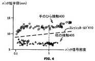
手のひら接触を指先又は親指接触から区別することは、特に困難であることが分かっている。というのは、手の小さな人の手のひら接触から生じるパッチ半径は、手の大きな人の親指又は指先接触により生じるパッチ半径に近いからである。これらの形式の接触も、本発明によれば、パッチ短半径パラメータを使用して区別することができる。図4を参照すれば、パッチ短半径に基づく手のひら接触400と他の接触405(例えば、指先及び親指)との間の区別を例示する実験データが示されている。パッチ信号密度値は、いかなるサイズのホバリング接触についても低くなる傾向があり、そして物体がタッチ表面をしっかり押圧するときには物体のサイズとは独立したレベルに飽和することが分かった。従って、手のひら・対・他の物体の判断スレッシュホールド410は、低い信号密度の接触に対して減少される。というのは、ホバリングする指又は軽くタッチする指は、しっかりタッチする指よりも小さい短半径を生じるが、手のひらは、ホバリングするときでも大きな短半径を生じる傾向があるからである。従って、判断スレッシュホールド410は、小さな正の勾配をもつまっすぐな曲線により表される。パッチ接触の厳密な値は、上述したように変化するが、スレッシュホールド410は、手のひら接触を他の接触から区別するように設けられることが図4から明らかであろう。この解決策を使用すると、ホバリングする手のひら(典型的にタッチする指と同様のパッチ信号密度値を発生する接触)が、カーソル移動又はボタンアクチベーション(例えば、「クリック」事象)として誤って解釈されるおそれが実質上なくなる。 It has proven particularly difficult to distinguish palm contact from fingertip or thumb contact. This is because the patch radius resulting from palm contact of a small hand person is close to the patch radius resulting from the thumb or fingertip contact of a large hand person. These types of contacts can also be distinguished using the patch short radius parameter according to the present invention. Referring to FIG. 4, experimental data illustrating the distinction between palm contacts 400 and other contacts 405 (eg, fingertips and thumbs) based on the patch minor radius is shown. It has been found that the patch signal density value tends to be low for any size of hovering contact and saturates to a level independent of the size of the object when the object firmly presses the touch surface. Thus, the palm / versus / other object decision threshold 410 is reduced for low signal density contacts. This is because a finger that is hovering or lightly touching produces a smaller minor radius than a finger that touches tightly, but the palm tends to produce a larger minor radius even when hovering. Thus, the decision threshold 410 is represented by a straight curve with a small positive slope. It will be apparent from FIG. 4 that the exact value of the patch contact varies as described above, but the threshold 410 is provided to distinguish the palm contact from other contacts. Using this solution, a hovering palm (typically a touch that produces a patch signal density value similar to a touching finger) is misinterpreted as a cursor movement or button activation (eg, a “click” event) The fear is virtually eliminated.
耳及び耳朶接触は、指及び親指により発生されるものとほぼ同じサイズのパッチを発生することができる。しかしながら、耳の皺や、隆起や、一般的に粗いトポグラフィーは、少なくとも映像センサ(即ち、タッチ表面)が耳の顕著な部分(即ち、肉質の耳朶だけではなく)をカバーする場合には、指及び親指とは独特の接近映像を発生することが分かった。上述した非正規性尺度は、接触の粗さを特徴付ける1つの方法である(式5を参照)。これは、耳及び耳朶による接触を、指、親指、頬、大腿、及び手のひらによる接触から弁別する健全な手段を許す。ここに定義された非正規性尺度は、耳及び耳朶接触の場合に1.0から2.0の値を与える傾向があるが、指、親指、手のひら及び頬に起因する正規の(例えば、平滑な)接触は、約1.0より小さい値を与える。図5を参照すれば、前記で定義された非正規性尺度に基づく耳接触500と他の接触505(例えば、指先、親指及び頬)との間の区別を例示する実験データが示されている。一実施形態では、スレッシュホールド510は、非正規性尺度が約1.0から1.2の第1レベルと、約1.1から1.2の第2レベルとを伴う直線段階状又はスプライン構造を備えている。別の実施形態では、正の勾配を有する単一の一次関数が使用される。更に別の実施形態では、より上位レベルの関数を使用して種々の接触形式を分離する。上述したように、パッチ接触のための厳密な値は、図5に示したものから変化するが、最も粗い物体接触を、ここに定義された非正規性尺度を使用して、最も滑らかな又は正規性の物体接触から区別できることが明らかであり、ここで、判断スレッシュホールド(例えば、スレッシュホールド510)の厳密な性質又は形態は、ターゲットとするマルチタッチ装置の正確な実施、動作目標及び能力に依存する。 Ear and earlobe contact can generate patches of approximately the same size as those generated by fingers and thumbs. However, ear ridges, ridges, and generally rough topography, at least when the image sensor (ie touch surface) covers a prominent part of the ear (ie not just the fleshy ear bud), It was found that the finger and thumb generate unique approach images. The non-normality measure described above is one way to characterize the roughness of contact (see Equation 5). This allows a sound means of discriminating ear and earlobe contact from finger, thumb, cheek, thigh and palm contacts. The non-normality scale defined here tends to give values between 1.0 and 2.0 in the case of ear and earlobe contact, but canonical (eg smoothness) due to fingers, thumbs, palms and cheeks. Contact) gives a value less than about 1.0. Referring to FIG. 5, experimental data illustrating the distinction between ear contacts 500 and other contacts 505 (eg, fingertips, thumbs and cheeks) based on the non-normality measure defined above is shown. . In one embodiment, threshold 510 is a linear stepped or spline structure with a first level with a non-normality measure of about 1.0 to 1.2 and a second level of about 1.1 to 1.2. It has. In another embodiment, a single linear function with a positive slope is used. In yet another embodiment, higher level functions are used to separate the various contact types. As noted above, the exact value for patch contact varies from that shown in FIG. 5, but the roughest object contact is either the smoothest or the non-normality scale defined here, It is clear that it can be distinguished from normal object contact, where the exact nature or form of the decision threshold (eg, threshold 510) depends on the exact implementation, operational goals and capabilities of the targeted multi-touch device. Dependent.
一実施形態では、次々の接近映像(別名「フレーム」)を使用し、タッチ表面を横切って物体が移動するときにその物体を追跡する。例えば、物体がタッチ表面を横切って移動されるときに、それに関連したパッチ(1つ又は複数)を、重畳計算を通して相関させることができる。即ち、指定数のピクセル(又はパッチピクセルの一部分)が重畳する次々の映像において識別されたパットは、同じ物体により生じると解釈することができる。このような実施形態では、追跡される接触の寿命にわたる最大パッチ短半径を、上述したスレッシュホールド(例えば、図3のスレッシュホールド310、図4の410、及び図5の510)と比較することができる。この解決策は、例えば、短半径が一時的に判断スレッシュホールド(例えば、410)より小さくなった場合に、手のひら接触が手のひらのアイデンティティを失わないことを保証する。更に、判断スレッシュホールドが、一定値(例えば、310)でなく、むしろ、ある程度カーブしている(例えば、410及び510)場合には、ここに述べる最大短半径累積動作の前に瞬時短半径に密度修正を適用するのが好都合である。 In one embodiment, successive approach images (aka “frames”) are used to track an object as it moves across the touch surface. For example, as an object is moved across the touch surface, its associated patch (s) can be correlated through a superposition calculation. That is, the putts identified in successive images over which a specified number of pixels (or portions of patch pixels) overlap can be interpreted as being caused by the same object. In such embodiments, the maximum patch minor radius over the life of the tracked contact can be compared to the thresholds described above (eg, threshold 310 in FIG. 3, 410 in FIG. 4, and 510 in FIG. 5). it can. This solution ensures that palm contact does not lose palm identity if, for example, the short radius is temporarily less than the decision threshold (eg, 410). Further, if the decision threshold is not a constant value (eg, 310), but rather is curved to some extent (eg, 410 and 510), the instantaneous short radius is set to the maximum short radius accumulation operation described herein. It is convenient to apply density correction.
マルチタッチ装置をポケットに入れたり出したりするか、さもなければ、一般的にそれを取り扱うときに、ユーザは、偽の入力を発生せずに、その周りを手で握る自由度をもたねばならない。このような指での把持は、次の基準のいずれか1つにより検出することができる。
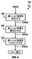
●5、6又はそれ以上の個別の表面接触の識別(図1のブロック125による)。(カードのデッキのサイズのタッチ表面に対して、この多数の指先は、通常、表面に適合しないが、平らにされた各指の指骨関節が2つ以上の接触パッチへセグメント化されるので、2つ又は3つの平らにされた指は、5つ以上の接触パッチを発生する。)
●2、3又はそれ以上の接触パッチが識別され、そして少なくとも2つの長半径が約15mmないし18mmを越える。頬及び他の大きな身体部分は、通常、大きな長半径をもつ1つのパッチしか生じないので、2つ又は3つの大きなパッチに対する要求は、頬、脚又は胸においてこのテストをトリガーするのを防止する。又、複数の大きな長半径に対する要求は、表面に対して長い親指を平らに置いて2つの指先でこのテストをトリガーするのを防止する。When a multi-touch device is put in and out of a pocket, or otherwise generally handled, the user should have the freedom to grip around it without generating fake input. Don't be. Such gripping with a finger can be detected by any one of the following criteria.
Identification of 5, 6 or more individual surface contacts (according to block 125 in FIG. 1). (For a card deck-sized touch surface, this multiple fingertip is usually not compatible with the surface, but because each flattened phalangeal joint is segmented into two or more contact patches, (2 or 3 flattened fingers will generate 5 or more contact patches.)
Two, three or more contact patches are identified and at least two major radii are greater than about 15 mm to 18 mm. The requirement for two or three large patches prevents triggering this test on the cheeks, legs or chest, as the cheeks and other large body parts typically only produce one patch with a large major radius. . Also, the requirement for multiple large radii prevents the test from being triggered by two fingertips with a long thumb lying flat against the surface.
本発明の別の実施形態では、マルチタッチ処理方法は、遠フィールド処理を含む。ここで使用する、遠フィールド処理とは、タッチ表面に接近はする(例えば、1mm未満から1cm以上まで)が接触はしない身体(例えば、指、手のひら、頬、耳、大腿、・・・)に関連した検出及び処理を指す。遠フィールド物体を検出する能力は、通常の使用中に、ユーザに接近するようにもっていかれるタッチ表面装置において有益である。このような装置の一例は、ユーザ入力(例えば、ダイヤリング)のためのタッチ表面を含む電話である。 In another embodiment of the present invention, the multi-touch processing method includes far field processing. As used herein, far field processing refers to a body (eg, finger, palm, cheek, ear, thigh,...) That approaches the touch surface (eg, less than 1 mm to 1 cm or more) but does not touch. Refers to related detection and processing. The ability to detect far-field objects is beneficial in touch surface devices that are brought closer to the user during normal use. An example of such a device is a phone that includes a touch surface for user input (eg, dialing).
図6を参照すれば、一実施形態において、接近映像データが取得された後に、初期の遠フィールド処理を行うことができる。即ち、図1のブロック105に基づく動作の後である。遠フィールド測定が、タッチ表面の付近に物体がないときに負のままであり、そして大きな物体が存在するときだけ正になるように設計された場合には、第1ステップは、最初に取得された接近映像から小さなノイズファクタを減算して、負の背景の遠フィールド映像を生成する(ブロック600)。
負の遠フィールド映像=[PROX]−(ノイズファクタ) 式9
一実施形態では、ノイズファクタは、全映像にわたり測定又は予想される平均ノイズの約1ないし2標準偏差にセットすることができる。これは、得られる負の遠フィールド映像内のほとんどのピクセルを、タッチ表面接触が存在しないときに、中性ではなく、若干負にさせる。図6に示すように、ブロック600に基づく動作から生じる負の遠フィールド映像は、[NFAR]と示されている。Referring to FIG. 6, in one embodiment, an initial far field process can be performed after the approach video data is acquired. That is, after the operation based on
Negative far-field image = [PROX] − (noise factor) Equation 9
In one embodiment, the noise factor can be set to about 1 to 2 standard deviations of the average noise measured or expected over the entire video. This causes most pixels in the resulting negative far field image to be slightly negative rather than neutral when there is no touch surface contact. As shown in FIG. 6, the negative far field image resulting from the operation based on
次いで、[NFAR]映像の各ピクセルは、タッチ表面から数ミリメータホバリングしている物体から予想される最高レベルへ飽和される(ブロック605)。一実施形態では、それにより得られる遠フィールド飽和映像(図6に[SFAR]と示された)は、テーブル3に示すように発生される。
遠フィールド動作の目標は、少数の非常にアクティブなピクセル(例えば、大きな正の値を有する)によって圧倒されることなく、若干アクチベートされただけの(例えば、小さな正の値を有する)非常に多数のピクセルを感知することであるから、飽和限界値は、タッチ表面の約1ないし2mm以内でホバリングしている指又は親指からのピークピクセル値未満でなければならないが、得られる[SFAR]映像が多くの情報コンテンツを失うようにさせるほど小さくてはならない。正確な遠フィールド飽和限界値は、(センサ素子技術及び関連回路が異なるために)実施形態ごとに変化するが、適当な値は、一般的に、初期の遠フィールド映像に関連したノイズの+3標準偏差と+6標準偏差との間であることが実験で決定された。(この場合も、このノイズは、ピクセルごと、又は全映像ベースである。) The goal of far-field operation is a very large number (eg having a small positive value) that is only slightly activated without being overwhelmed by a small number of very active pixels (eg having a large positive value) The saturation limit should be less than the peak pixel value from a finger or thumb hovering within about 1 to 2 mm of the touch surface, but the resulting [SFAR] image is It must not be so small that you lose so much information content. Although the exact far field saturation limit varies from embodiment to embodiment (because of different sensor element technology and associated circuitry), an appropriate value is generally a +3 standard of noise associated with the initial far field image. It was experimentally determined to be between the deviation and +6 standard deviation. (Again, this noise is pixel-by-pixel or full-video based.)
初期の接近映像[PROX]が著しい量のノイズを含む場合には、[SFAR]映像をフィルタリングするのが有益である(ブロック610)。一実施形態では、2つ以上の連続的な[SFAR]映像が一緒に平均化される有限インパルス応答フィルタ技術を使用することができる。別の実施形態では、無限インパルス応答フィルタ技術を使用して、平滑化された映像を発生することができる。無限インパルス応答フィルタは、重み付けされたランニング平均(又は自動回帰)映像を発生することが明らかである。一実施形態では、例えば、無限インパルス応答フィルタは、現在遠フィールド飽和映像(例えば、[SFAR]new)を、その直前の遠フィールド飽和映像(例えば、[SFAR]prior)と1対3ないし2対3の比で合成する。図6に示すように、ブロック610に基づいて発生されたフィルタされた遠フィールド飽和映像は、[FARF]と示されている。If the initial approach image [PROX] contains a significant amount of noise, it may be beneficial to filter the [SFAR] image (block 610). In one embodiment, a finite impulse response filter technique can be used in which two or more consecutive [SFAR] images are averaged together. In another embodiment, an infinite impulse response filter technique can be used to generate a smoothed image. It is clear that the infinite impulse response filter generates a weighted running average (or autoregressive) image. In one embodiment, for example, the infinite impulse response filter may be configured such that the current far field saturated image (eg, [SFAR]new ) and the previous far field saturated image (eg, [SFAR]prior ) are 1 to 3 to 2 pairs. Synthesize at a ratio of 3. As shown in FIG. 6, the filtered far field saturated image generated based on
ブロック125(図1を参照)に基づく映像セグメント化動作に続いて、非線型スケールの背景ピクセル値の重み付けされた平均を使用して、本発明によるスカラーの遠フィールドインジケータ値(FAR−FIELD)を次のように発生することができる。
一実施形態では、ENeg()関数は、背景ピクセルからの貢献を次のように不均衡に強調させる。
必要ではないが、式10及び11に基づき背景ピクセルからの貢献を不均衡に強調することは、タッチ表面のほとんどのピクセルに積極的に作用するに充分な大きさの身体(例えば、頬及び脚)に対してFAR-FIELD測定値がより敏感であるようにするが、中間サイズの物体(例えば、ホバリングしている親指)により著しく影響されないようにする。例えば、ホバリングしている親指が、タッチ表面のセンサ素子の半分に背景ピクセルより若干上の値をもたせる場合には、背景より低いままである半分を不均衡に強調することで、FAR-FIELDの測定値をゼロより低く保持し、これは、大きな物体がタッチ表面の「近く」(例えば、1ないし3cm以内)にないことを指示する。別の実施形態では、背景ピクセルが直線的に合成(例えば、加算)されてもよい。 Although not required, disproportionately emphasizing the contribution from background pixels based on
上述したように、[LOC]は、ピクセル重み付けメカニズムを表す。一般的に、タッチ表面に存在するピクセルごとに1つの値が[LOC]にある。全てのタッチ表面ピクセルを等しく考慮することが望まれる場合には、[LOC]映像の各値を1.0(又はある同様の一定値)にセットすることができる。しかしながら、ハンドヘルドフォームファクタについては、底縁及び側縁付近の重みを(例えば、0.1ないし0.9の値)に下げることにより、大きな本体に対する選択性を改善することができる。これを行うことで、(把持)操作中に指が装置の周りを包むところの手からの偽の積極的な貢献を減少することができる。移動電話のフォームファクタでは、耳及び頬の遠フィールドに対する感度を保つために、上縁(親指及び指がホバリングしたり又はそれを包んだりするおそれが低い)に沿った重みがその全強度に保持される。 As described above, [LOC] represents a pixel weighting mechanism. In general, there is one value in [LOC] for each pixel present on the touch surface. If it is desired to consider all touch surface pixels equally, each value in the [LOC] image can be set to 1.0 (or some similar constant value). However, for handheld form factors, selectivity for large bodies can be improved by lowering the weights near the bottom and side edges (eg, values between 0.1 and 0.9). By doing this, the false positive contribution from the hands where the fingers wrap around the device during the (grip) operation can be reduced. In the mobile phone form factor, weights along the upper edge (low risk of thumb and fingers hovering or wrapping them) are kept at their full strength to maintain sensitivity to the far field of the ears and cheeks Is done.
ここで、図1を参照すれば、ブロック140において、接触弁別動作中に遠フィールド測定値を考慮するときに、指定のスレッシュホールド(例えば、ゼロ)より大きいFAR-FIELD値は、大きな「近傍」物体が検出されたことを指示する。上述したように、この情報を使用して、タッチ表面装置を指定のモード(例えば、オン、オフ又は低電力)へ移行させることができる。更に、遠フィールド測定値を他の測定値(例えば、非正規性尺度)と合成して、改良された耳検出を与えることができる。例えば、タッチ表面が部分的に耳に接していると共に頬から1又は2cmのところでホバリングしているときには、ブロック125に基づき、スクリーンの頂部で、弱い耳ピクセルパッチをセグメント化することができる。その間に、タッチ表面の中央及び底部は、頬の遠フィールドにより影響されるだけである。耳パッチの外部で得られたFAR-FIELD測定値が、それ自身の指定のFAR-FIELDスレッシュホールドを越えるに充分な強さでない場合でも、FAR-FIELD値を(弱い)パッチ密度及び非正規性尺度インジケータに加算するか、さもなければ、合成して、その和又は組合せで耳検出スレッシュホールドを越えるようにすることができる。 Referring now to FIG. 1, in
更に、タッチ表面の上縁の上、又は例えば、電話受話部の開口の周りに1つ以上の接近センサを配置することができる。この形式の接近センサは、アクティブな赤外線反射センサ及びキャパシタンス感知電極ストリップを含むが、これに限定されない。移動電話フォームファクタでは、受話部が耳導管を中心とするように装置が保持されたときに、耳の隆起部が接近センサをトリガーする。その間に、耳朶がタッチ表面の頂部に小さなピクセルパッチを生じさせる。ブロック140に基づく弁別動作は、著しい受話部接近トリガーに付随してタッチ表面の頂部のピクセルパッチが生じたときに、ピクセルパッチが、指ではなく、耳であることを判断できる。別の実施形態では、同じ条件であるが、タッチ表面の下部に対して著しいFAR-FIELD値を伴う(ホバリングする頬を指示する)ことを使用して、タッチ表面の頂部において耳の検出をトリガーすることができる。一般的に述べると、信号密度(式7及び8を参照)、パッチ非正規性(式5を参照)FAR-FIELD測定値(式10を参照)、及び接近センサ入力の1つ以上を合成し(例えば、重み付けされた平均)、複数のインジケータが弱くアクティブであるか又は1つのインジケータのみが強くアクティブであるときに耳検出をトリガーできるようにする。最終的に、パッチのセントロイド、短軸半径、パッチ非正規性(式5)、パッチ信号密度(式7及び8)遠フィールド(式10)、及び接近センサ入力(もし得られれば)のような接触弁別パラメータを(ローパス)フィルタリングして、頻繁な散在性を打ち消す上で助けとなることに注意されたい。これは、上昇する入力値に応答して迅速に上昇するが、入力値が降下し及び/又は欠落したときにはゆっくり減衰する適応時定数をフィルタが使用する場合に、特に有益である。 In addition, one or more proximity sensors can be placed on the upper edge of the touch surface or, for example, around the opening of the telephone receiver. This type of proximity sensor includes, but is not limited to, an active infrared reflection sensor and a capacitance sensing electrode strip. In the mobile telephone form factor, the ear ridge triggers the proximity sensor when the device is held so that the earpiece is centered on the ear conduit. In the meantime, the earlobe produces a small pixel patch on the top of the touch surface. The discriminating action based on
図7を参照すれば、ここに述べる形式のタッチ表面装置700がブロック図の形態で示されている。ここで使用するタッチ表面装置とは、マルチタッチ可能なタッチ表面コンポーネント(即ち、接近映像の形態のユーザ入力を与える入力ユニット)からユーザ入力を受け取る装置である。ここに例示するタッチ表面装置は、タブレットコンピュータシステム、ノートブックコンピュータシステム、ポータブル音楽及びビデオディスプレイ装置、パーソナルデジタルアシスタント並びに移動電話を含むが、これらに限定されない。 Referring to FIG. 7, a
図示されたように、タッチ表面要素705は、センサ素子、並びに必要なドライブ及び信号取得及び検出回路を含む。メモリ710は、取得した接近映像情報(例えば、[PROX]映像データ)を保持するのに使用されると共に、計算された映像情報(例えば、パッチ特徴付けパラメータ)に対してプロセッサ715により使用される。プロセッサ715は、タッチ表面要素705により発生された情報を使用して図1に基づく種々のメトリックを決定することのできる計算ユニット又はプログラム可能な制御装置を表す。更に、外部コンポーネント720は、発生された情報を使用するエンティティを表す。ここに例示する実施形態では、外部コンポーネント720は、プロセッサ715から、又はメモリ710から直接的に、情報を得ることができる。例えば、プロセッサ715は、例えば、大きな身体接触状態、大きな身体遠フィールド状態、非正規性物体指示状態、接近センサ状態(もし使用されれば)、平らな指握り状態、及び通常の指タッチ状態の指示を保持するためのデータ構造をメモリ710に維持することができる。一実施形態では、各状態は、単一のブール値(即ち、フラグ)により指示することができる。 As shown, the
特許請求の範囲から逸脱せずに、材料、コンポーネント、回路素子、並びにここに例示する操作方法の細部に種々の変更がなされ得る。例えば、図1に示す全てのステップを遂行する必要はなく、一方、他のステップを組み合わせ且つ他のステップを更に洗練されたステップへと分割できることも明らかであろう。例えば、一実施形態では、パッチ周辺ピクセルノイズが抑制されない(ブロック130を参照)。別の実施形態では、パッチ周辺ピクセルノイズ抑制が使用されるが、パッチ非正規性尺度は作られない(ブロック120を参照)。更に別の実施形態では、パッチ周辺ピクセルノイズ抑制及びパッチ非正規性尺度の両方が決定され使用される。周辺パッチピクセルノイズ減少技術を使用しない実施形態については、ブロック135によるパッチパラメータ化動作は、上述した[CNST]映像は使用するが、[CNST’]映像は使用しない(テーブル2を参照)。更に、ブロック135によるパッチパラメータ化動作は、統計学的な楕円適合に依存する必要がない。それらは、むしろ、パッチ周辺ピクセルを総和し、そして得られた値を全てのパッチピクセルと比較するか、或いは多角形適合を試みる。更に、校正動作(テーブル1及び2を参照)は、映像セグメント化動作(ブロック125)まで遅延されるか、又はその一部分として行われる。更に、映像セグメント化の目的で、背景レベルにあるか又はそこにセットされたピクセルをマークすることが有益である(例えば、ブロック110による動作中に)。又、指把持を識別するための基準は、大きな身体接触の検出に対して直交するので(〔0037〕の説明を参照)、平らな指把持を、スクリーンをロックし、スリープに至らせ、又は電話コールを終了するような特定の動作を指令する個別のジェスチャーとして使用することができる。 Various changes may be made in the details of the materials, components, circuit elements, and operating methods illustrated herein, without departing from the scope of the claims. For example, it will be apparent that not all steps shown in FIG. 1 need to be performed, while other steps can be combined and other steps can be divided into more sophisticated steps. For example, in one embodiment, patch peripheral pixel noise is not suppressed (see block 130). In another embodiment, patch peripheral pixel noise suppression is used, but no patch denormality measure is created (see block 120). In yet another embodiment, both patch peripheral pixel noise suppression and patch non-normality measures are determined and used. For embodiments that do not use the peripheral patch pixel noise reduction technique, the patch parameterization operation by
ここに例示するタッチ表面装置700に関して、タッチ表面要素705は、メモリ(例えば、710)及び/又はプロセッサ(例えば、715)機能を組み込むことができる。更に、外部コンポーネント720は、ハードウェア要素(例えば、ホストプロセッサ)又はソフトウェア要素(例えば、ドライバユーティリティ)を表す。 With respect to the
最後に、図1、2及び6に基づく動作は、1つ以上のプログラムモジュールへと編成されたインストラクションを実行するプログラム可能な制御装置によって遂行することができる。プログラム可能な制御装置は、単一のコンピュータプロセッサ、特殊目的のプロセッサ(例えば、デジタル信号プロセッサ“DSP”)、通信リンクにより結合された複数のプロセッサ、又はカスタム設計のステートマシンでよい。カスタム設計のステートマシンは、集積回路のようなハードウェア装置で実施されてもよく、これは、特定用途向け集積回路(ASIC)、又は現場でプログラム可能なゲートアレー(FPGA)を含むが、それに限定されない。又、プログラムインストラクションを有形に実施するのに適した記憶装置は、磁気ディスク(固定、フロッピー及び取り外し可能な)及びテープ;光学的媒体、例えば、CD−ROM、及びデジタルビデオディスク(DVD);並びに半導体メモリデバイス、例えば、電気的にプログラム可能なリードオンリメモリ(EPROM)、電気的に消去可能でプログラム可能なリードオンリメモリ(EEPROM)、プログラム可能なゲートアレー、及びフラッシュ装置を含むが、これらに限定されない。 Finally, the operations according to FIGS. 1, 2 and 6 can be performed by a programmable controller that executes instructions organized into one or more program modules. The programmable controller may be a single computer processor, a special purpose processor (eg, a digital signal processor “DSP”), multiple processors coupled by a communication link, or a custom designed state machine. Custom-designed state machines may be implemented in hardware devices such as integrated circuits, including application specific integrated circuits (ASICs) or field programmable gate arrays (FPGAs), It is not limited. Storage devices suitable for tangibly implementing program instructions include magnetic disks (fixed, floppy and removable) and tapes; optical media such as CD-ROMs and digital video disks (DVDs); and Semiconductor memory devices, including electrically programmable read only memory (EPROM), electrically erasable and programmable read only memory (EEPROM), programmable gate arrays, and flash devices include, but are not limited to, It is not limited.
100:マルチタッチ処理方法
300:頬接触
305:他の接触
310:スレッシュホールド
400:手のひら接触
405:他の接触
410:判断スレッシュホールド
500:耳接触
505:他の接触
510:判断スレッシュホールド
700:装置
705:タッチ表面要素
710:メモリ
715:プロセッサ
720:外部コンポーネント100: Multi-touch processing method 300: Cheek contact 305: Other contact 310: Threshold 400: Palm contact 405: Other contact 410: Judgment threshold 500: Ear contact 505: Other contact 510: Judgment threshold 700: Apparatus 705: Touch surface element 710: Memory 715: Processor 720: External component
Claims (72)
Translated fromJapanese接近映像を得るステップと、
前記接近映像をセグメント化して、複数のパッチを識別するステップと、
前記複数のパッチの各々に対する短軸半径値を決定するステップと、
前記パッチの短軸半径値が第1の指定のスレッシュホールドより上である場合には前記複数のパッチの1つを大きな物体に関連したものとして識別するステップと、
前記識別されたパッチを使用して、タッチ表面装置の動作を制御するステップと、
を備えた方法。In a method of discriminating input sources to a touch surface device,
Obtaining a close-up image;
Segmenting the approach video to identify a plurality of patches;
Determining a minor axis radius value for each of the plurality of patches;
Identifying one of the plurality of patches as associated with a large object if the minor axis radius value of the patch is above a first specified threshold;
Controlling the operation of the touch surface device using the identified patch;
With a method.
前記識別された第2パッチを使用して、タッチ表面装置の動作を制御するステップと、
を更に備えた請求項1に記載の方法。If the minor axis value of the second patch of the plurality of patches is less than the first specified threshold and greater than the second specified threshold, the second patch is identified as associated with a palm. Steps,
Controlling the operation of the touch surface device using the identified second patch;
The method of claim 1 further comprising:
前記識別された第3パッチを使用して、タッチ表面装置の動作を制御するステップと、
を更に備えた請求項4に記載の方法。Identifying the third patch as being associated with a finger if a minor axis value of a third patch of the plurality of patches is less than the second specified threshold;
Controlling the operation of the touch surface device using the identified third patch;
The method of claim 4 further comprising:
各々値を有する複数のピクセルで構成される第1の接近映像を得る段階と、
前記第1の接近映像における複数のピクセル値からセンサ素子の基線値を減算する段階と、
を含む、請求項1に記載の方法。The obtaining step comprises
Obtaining a first approach image comprised of a plurality of pixels each having a value;
Subtracting a baseline value of a sensor element from a plurality of pixel values in the first approach image;
The method of claim 1 comprising:
第1の接近映像を得る段階と、
前記第1の接近映像をフィルタリングして、フィルタリングされた接近映像を発生する段階と、
を含む、請求項1に記載の方法。The obtaining step comprises
Obtaining a first approach image;
Filtering the first approach image to generate a filtered approach image;
The method of claim 1 comprising:
前記マルチタッチ入力タッチ表面から接近映像を受け取る手段と、
請求項1に記載の動作を遂行する処理手段と、
を備えたポータブル電子装置。A multi-touch input touch surface component;
Means for receiving an approach image from the multi-touch input touch surface;
Processing means for performing the operation of claim 1;
Portable electronic device with
接近映像を得るステップと、
前記接近映像をセグメント化して、パッチを識別するステップと、
前記パッチに対する短軸半径値を決定するステップと、
前記パッチの短軸半径値が第1の指定のスレッシュホールドより上である場合には前記パッチを大きな物体に関連したものとして識別するステップと、
前記識別されたパッチを使用して、マルチタッチのタッチ表面装置の動作を制御するステップと、
を備えた方法。In a method for identifying an input source to a multi-touch touch surface device,
Obtaining a close-up image;
Segmenting the approach video to identify patches;
Determining a minor axis radius value for the patch;
Identifying the patch as associated with a large object if the minor axis radius value of the patch is above a first specified threshold;
Controlling the operation of a multi-touch touch surface device using the identified patch;
With a method.
接近映像を得るステップと、
前記接近映像をセグメント化して、パッチを識別するステップと、
前記パッチに対する短軸半径値を決定するステップと、
前記パッチの短軸値が第1の指定のスレッシュホールドより小さく且つ第2の指定のスレッシュホールドより大きい場合には前記パッチを手のひらに関連したものとして識別するステップと、
前記識別されたパッチを使用して、マルチタッチのタッチ表面装置の動作を制御するステップと、
を備えた方法。In a method for identifying an input source to a multi-touch touch surface device,
Obtaining a close-up image;
Segmenting the approach video to identify patches;
Determining a minor axis radius value for the patch;
Identifying the patch as being associated with a palm if the minor axis value of the patch is less than a first specified threshold and greater than a second specified threshold;
Controlling the operation of a multi-touch touch surface device using the identified patch;
With a method.
接近映像を得るステップと、
前記接近映像をセグメント化して、パッチを識別するステップと、
前記パッチに対する短軸半径値を決定するステップと、
前記パッチの短軸値が第2の指定のスレッシュホールドより小さい場合には前記パッチを指に関連したものとして識別するステップと、
前記識別されたパッチを使用して、マルチタッチのタッチ表面装置の動作を制御するステップと、
を備えた方法。In a method for identifying an input source to a multi-touch touch surface device,
Obtaining a close-up image;
Segmenting the approach video to identify patches;
Determining a minor axis radius value for the patch;
Identifying the patch as being associated with a finger if the minor axis value of the patch is less than a second specified threshold;
Controlling the operation of a multi-touch touch surface device using the identified patch;
With a method.
接近映像を得るステップと、
前記接近映像をセグメント化して、複数のパッチを識別するステップと、
前記識別されたパッチの少なくとも5つがタッチ表面への指接触に関連していることを決定するステップと、
前記少なくとも5つの識別されたパッチが指把持操作に関連したものであると識別するステップと、
前記識別された指把持操作を使用して、マルチタッチのタッチ表面装置の動作を制御するステップと、
を備えた方法。In a method for identifying an input source to a multi-touch touch surface device,
Obtaining a close-up image;
Segmenting the approach video to identify a plurality of patches;
Determining that at least five of the identified patches are associated with finger contact with a touch surface;
Identifying the at least five identified patches as being associated with a finger gripping operation;
Controlling the operation of the multi-touch touch surface device using the identified finger gripping operation;
With a method.
接近映像を得るステップと、
前記接近映像をセグメント化して、複数のパッチを識別するステップと、
前記識別されたパッチの少なくとも2つが約15mmより大きい長軸半径値を有することを決定するステップと、
前記少なくとも2つの識別されたパッチが指把持操作に関連したものであると識別するステップと、
前記識別された指把持操作を使用して、マルチタッチのタッチ表面装置の動作を制御するステップと、
を備えた方法。In a method for identifying an input source to a multi-touch touch surface device,
Obtaining a close-up image;
Segmenting the approach video to identify a plurality of patches;
Determining that at least two of the identified patches have a major axis radius value greater than about 15 mm;
Identifying the at least two identified patches as being associated with a finger gripping operation;
Controlling the operation of the multi-touch touch surface device using the identified finger gripping operation;
With a method.
接近映像を得るステップと、
前記接近映像をセグメント化して、各々値をもつ複数のピクセルを各々有する1つ以上のパッチを識別するステップと、
前記1つ以上のパッチの少なくとも1つに対して信号密度値を決定するステップと、
前記少なくとも1つのパッチが指定値より大きい信号密度値を有する場合には、前記少なくとも1つのパッチを、タッチ表面装置のタッチ表面に接触する物体に関連したものとして識別するステップと、
前記少なくとも1つのパッチが前記指定値未満の信号密度値を有する場合には、前記少なくとも1つのパッチを、タッチ表面上にホバリングする物体に関連したものとして識別するステップと、
前記識別の動作に応答して前記タッチ表面装置の制御動作を遂行するステップと、
を備えた方法。In a method for identifying an input source to a touch surface device,
Obtaining a close-up image;
Segmenting the approach video to identify one or more patches each having a plurality of pixels each having a value;
Determining a signal density value for at least one of the one or more patches;
Identifying the at least one patch as being associated with an object in contact with a touch surface of a touch surface device if the at least one patch has a signal density value greater than a specified value;
Identifying the at least one patch as being associated with an object hovering over a touch surface if the at least one patch has a signal density value less than the specified value;
Performing a control operation of the touch surface device in response to the identifying operation;
With a method.
Applications Claiming Priority (3)
| Application Number | Priority Date | Filing Date | Title |
|---|---|---|---|
| US11/619,464 | 2007-01-03 | ||
| US11/619,464US7855718B2 (en) | 2007-01-03 | 2007-01-03 | Multi-touch input discrimination |
| PCT/US2007/026145WO2008085404A2 (en) | 2007-01-03 | 2007-12-21 | Multi-touch input discrimination |
Related Child Applications (1)
| Application Number | Title | Priority Date | Filing Date |
|---|---|---|---|
| JP2011013813ADivisionJP2011118919A (en) | 2007-01-03 | 2011-01-26 | Multi-touch input discrimination |
Publications (2)
| Publication Number | Publication Date |
|---|---|
| JP2010515192Atrue JP2010515192A (en) | 2010-05-06 |
| JP4711095B2 JP4711095B2 (en) | 2011-06-29 |
Family
ID=39402673
Family Applications (4)
| Application Number | Title | Priority Date | Filing Date |
|---|---|---|---|
| JP2009544844AExpired - Fee RelatedJP4711095B2 (en) | 2007-01-03 | 2007-12-21 | Multi-touch input discrimination |
| JP2011013813APendingJP2011118919A (en) | 2007-01-03 | 2011-01-26 | Multi-touch input discrimination |
| JP2013268782AExpired - Fee RelatedJP6077990B2 (en) | 2007-01-03 | 2013-12-26 | Multi-touch input discrimination |
| JP2017004294AExpired - Fee RelatedJP6561079B2 (en) | 2007-01-03 | 2017-01-13 | Multi-touch input discrimination |
Family Applications After (3)
| Application Number | Title | Priority Date | Filing Date |
|---|---|---|---|
| JP2011013813APendingJP2011118919A (en) | 2007-01-03 | 2011-01-26 | Multi-touch input discrimination |
| JP2013268782AExpired - Fee RelatedJP6077990B2 (en) | 2007-01-03 | 2013-12-26 | Multi-touch input discrimination |
| JP2017004294AExpired - Fee RelatedJP6561079B2 (en) | 2007-01-03 | 2017-01-13 | Multi-touch input discrimination |
Country Status (7)
| Country | Link |
|---|---|
| US (3) | US7855718B2 (en) |
| EP (7) | EP2102736A2 (en) |
| JP (4) | JP4711095B2 (en) |
| KR (1) | KR101109241B1 (en) |
| CN (4) | CN105549783B (en) |
| AU (1) | AU2007342439B2 (en) |
| WO (1) | WO2008085404A2 (en) |
Cited By (2)
| Publication number | Priority date | Publication date | Assignee | Title |
|---|---|---|---|---|
| JP2013084223A (en)* | 2011-10-12 | 2013-05-09 | Fuji Xerox Co Ltd | Touch detection device, recording display device, and program |
| WO2015181680A1 (en)* | 2014-05-30 | 2015-12-03 | 株式会社半導体エネルギー研究所 | Information processing device |
Families Citing this family (247)
| Publication number | Priority date | Publication date | Assignee | Title |
|---|---|---|---|---|
| US7834855B2 (en) | 2004-08-25 | 2010-11-16 | Apple Inc. | Wide touchpad on a portable computer |
| US7333092B2 (en) | 2002-02-25 | 2008-02-19 | Apple Computer, Inc. | Touch pad for handheld device |
| US7561146B1 (en) | 2004-08-25 | 2009-07-14 | Apple Inc. | Method and apparatus to reject accidental contact on a touchpad |
| US20070152983A1 (en) | 2005-12-30 | 2007-07-05 | Apple Computer, Inc. | Touch pad with symbols based on mode |
| US7509588B2 (en) | 2005-12-30 | 2009-03-24 | Apple Inc. | Portable electronic device with interface reconfiguration mode |
| US8144125B2 (en) | 2006-03-30 | 2012-03-27 | Cypress Semiconductor Corporation | Apparatus and method for reducing average scan rate to detect a conductive object on a sensing device |
| US8062115B2 (en)* | 2006-04-27 | 2011-11-22 | Wms Gaming Inc. | Wagering game with multi-point gesture sensing device |
| US8022935B2 (en) | 2006-07-06 | 2011-09-20 | Apple Inc. | Capacitance sensing electrode with integrated I/O mechanism |
| US10313505B2 (en) | 2006-09-06 | 2019-06-04 | Apple Inc. | Portable multifunction device, method, and graphical user interface for configuring and displaying widgets |
| WO2008045464A2 (en)* | 2006-10-10 | 2008-04-17 | Wms Gaming Inc. | Multi-player, multi-touch table for use in wagering game systems |
| US8274479B2 (en) | 2006-10-11 | 2012-09-25 | Apple Inc. | Gimballed scroll wheel |
| KR100886337B1 (en)* | 2006-11-23 | 2009-03-02 | 삼성전자주식회사 | Device for collectively storing the selected area in the image and documenting device for image information |
| US8130203B2 (en) | 2007-01-03 | 2012-03-06 | Apple Inc. | Multi-touch input discrimination |
| US7855718B2 (en) | 2007-01-03 | 2010-12-21 | Apple Inc. | Multi-touch input discrimination |
| US7924271B2 (en)* | 2007-01-05 | 2011-04-12 | Apple Inc. | Detecting gestures on multi-event sensitive devices |
| US8519964B2 (en) | 2007-01-07 | 2013-08-27 | Apple Inc. | Portable multifunction device, method, and graphical user interface supporting user navigations of graphical objects on a touch screen display |
| US8144126B2 (en) | 2007-05-07 | 2012-03-27 | Cypress Semiconductor Corporation | Reducing sleep current in a capacitance sensing system |
| US8681104B2 (en)* | 2007-06-13 | 2014-03-25 | Apple Inc. | Pinch-throw and translation gestures |
| US8619038B2 (en) | 2007-09-04 | 2013-12-31 | Apple Inc. | Editing interface |
| WO2009032898A2 (en) | 2007-09-04 | 2009-03-12 | Apple Inc. | Compact input device |
| US8416198B2 (en) | 2007-12-03 | 2013-04-09 | Apple Inc. | Multi-dimensional scroll wheel |
| US8373549B2 (en) | 2007-12-31 | 2013-02-12 | Apple Inc. | Tactile feedback in an electronic device |
| US20090174676A1 (en) | 2008-01-04 | 2009-07-09 | Apple Inc. | Motion component dominance factors for motion locking of touch sensor data |
| US20090174679A1 (en) | 2008-01-04 | 2009-07-09 | Wayne Carl Westerman | Selective Rejection of Touch Contacts in an Edge Region of a Touch Surface |
| US8125461B2 (en) | 2008-01-11 | 2012-02-28 | Apple Inc. | Dynamic input graphic display |
| US8358142B2 (en) | 2008-02-27 | 2013-01-22 | Cypress Semiconductor Corporation | Methods and circuits for measuring mutual and self capacitance |
| US8319505B1 (en) | 2008-10-24 | 2012-11-27 | Cypress Semiconductor Corporation | Methods and circuits for measuring mutual and self capacitance |
| US9454256B2 (en) | 2008-03-14 | 2016-09-27 | Apple Inc. | Sensor configurations of an input device that are switchable based on mode |
| TWI366776B (en)* | 2008-04-21 | 2012-06-21 | Htc Corp | Operating method and system and stroage device using the same |
| US10180714B1 (en) | 2008-04-24 | 2019-01-15 | Pixar | Two-handed multi-stroke marking menus for multi-touch devices |
| US8799821B1 (en)* | 2008-04-24 | 2014-08-05 | Pixar | Method and apparatus for user inputs for three-dimensional animation |
| US8241912B2 (en)* | 2008-06-26 | 2012-08-14 | Wms Gaming Inc. | Gaming machine having multi-touch sensing device |
| US9218116B2 (en)* | 2008-07-25 | 2015-12-22 | Hrvoje Benko | Touch interaction with a curved display |
| US8816967B2 (en) | 2008-09-25 | 2014-08-26 | Apple Inc. | Capacitive sensor having electrodes arranged on the substrate and the flex circuit |
| US8294047B2 (en) | 2008-12-08 | 2012-10-23 | Apple Inc. | Selective input signal rejection and modification |
| KR101519980B1 (en)* | 2008-12-24 | 2015-05-14 | 삼성디스플레이 주식회사 | Method and apparatus for detecting a touch location and touch screen display apparatus having the same |
| US8922521B2 (en) | 2009-02-02 | 2014-12-30 | Apple Inc. | Switching circuitry for touch sensitive display |
| US20100251112A1 (en)* | 2009-03-24 | 2010-09-30 | Microsoft Corporation | Bimodal touch sensitive digital notebook |
| KR101844366B1 (en)* | 2009-03-27 | 2018-04-02 | 삼성전자 주식회사 | Apparatus and method for recognizing touch gesture |
| US8593410B2 (en) | 2009-04-10 | 2013-11-26 | Apple Inc. | Touch sensor panel design |
| US8446367B2 (en)* | 2009-04-17 | 2013-05-21 | Microsoft Corporation | Camera-based multi-touch mouse |
| US9354751B2 (en) | 2009-05-15 | 2016-05-31 | Apple Inc. | Input device with optimized capacitive sensing |
| JP5451181B2 (en)* | 2009-05-25 | 2014-03-26 | 株式会社ジャパンディスプレイ | Sensor device for detecting contact or proximity of an object |
| US8957874B2 (en) | 2009-06-29 | 2015-02-17 | Apple Inc. | Touch sensor panel design |
| US8723827B2 (en) | 2009-07-28 | 2014-05-13 | Cypress Semiconductor Corporation | Predictive touch surface scanning |
| US8269511B2 (en) | 2009-09-08 | 2012-09-18 | Synaptics Incorporated | Sensing and defining an input object |
| US8749512B2 (en) | 2009-09-30 | 2014-06-10 | Apple Inc. | Negative pixel compensation |
| JP5424475B2 (en)* | 2009-10-13 | 2014-02-26 | 株式会社ジャパンディスプレイ | Information input device, information input method, information input / output device, information input program, and electronic device |
| JP5621090B2 (en) | 2009-10-16 | 2014-11-05 | ビーボップ センサーズ、インコーポレイテッド | Foot-operated controller and computer-implemented method |
| CN102043501B (en) | 2009-10-26 | 2016-03-23 | 宸鸿光电科技股份有限公司 | Integrated cable module for force sensor and pressure-sensitive touch screen |
| KR101660842B1 (en)* | 2009-11-05 | 2016-09-29 | 삼성전자주식회사 | Touch input method and apparatus |
| JP5341719B2 (en)* | 2009-11-12 | 2013-11-13 | 京セラ株式会社 | Mobile communication terminal and input control program |
| JP5280989B2 (en)* | 2009-11-12 | 2013-09-04 | 京セラ株式会社 | Mobile terminal and control program |
| KR101105366B1 (en)* | 2009-12-31 | 2012-01-16 | 한국과학기술연구원 | Driving method of touch recognition device and touch recognition device |
| US8531412B1 (en) | 2010-01-06 | 2013-09-10 | Sprint Spectrum L.P. | Method and system for processing touch input |
| US10007393B2 (en)* | 2010-01-19 | 2018-06-26 | Apple Inc. | 3D view of file structure |
| CN102135827B (en)* | 2010-01-21 | 2015-01-07 | 苹果公司 | Negative pixel compensation method and device, touch sensor device and terminal device |
| US8581879B2 (en)* | 2010-01-21 | 2013-11-12 | Apple Inc. | Negative pixel compensation |
| US20110216016A1 (en)* | 2010-03-08 | 2011-09-08 | Plantronics, Inc. | Touch Sensor With Active Baseline Tracking |
| US8339286B2 (en) | 2010-03-31 | 2012-12-25 | 3M Innovative Properties Company | Baseline update procedure for touch sensitive device |
| US8881060B2 (en) | 2010-04-07 | 2014-11-04 | Apple Inc. | Device, method, and graphical user interface for managing folders |
| US10788976B2 (en) | 2010-04-07 | 2020-09-29 | Apple Inc. | Device, method, and graphical user interface for managing folders with multiple pages |
| US8878773B1 (en) | 2010-05-24 | 2014-11-04 | Amazon Technologies, Inc. | Determining relative motion as input |
| US20120013565A1 (en)* | 2010-07-16 | 2012-01-19 | Perceptive Pixel Inc. | Techniques for Locally Improving Signal to Noise in a Capacitive Touch Sensor |
| EP2418573A2 (en)* | 2010-08-13 | 2012-02-15 | Samsung Electronics Co., Ltd. | Display apparatus and method for moving displayed object |
| US9459733B2 (en)* | 2010-08-27 | 2016-10-04 | Inputdynamics Limited | Signal processing systems |
| KR20140008292A (en)* | 2010-09-15 | 2014-01-21 | 어드밴스드 실리콘 에스아 | Method for detecting an arbitrary number of touches from a multi-touch device |
| US9019207B1 (en) | 2010-09-28 | 2015-04-28 | Google Inc. | Spacebar integrated with trackpad |
| US8754854B1 (en) | 2010-09-28 | 2014-06-17 | Google Inc. | Keyboard integrated with trackpad |
| FR2967278B1 (en)* | 2010-11-08 | 2013-06-28 | Nanotec Solution | METHOD FOR DETECTING AN OBJECT OF INTEREST IN A DISTURBED ENVIRONMENT, AND GESTUAL INTERFACE DEVICE USING THE SAME |
| US20120127120A1 (en)* | 2010-11-22 | 2012-05-24 | Himax Technologies Limited | Touch device and touch position locating method thereof |
| US8988398B2 (en) | 2011-02-11 | 2015-03-24 | Microsoft Corporation | Multi-touch input device with orientation sensing |
| US8994646B2 (en) | 2010-12-17 | 2015-03-31 | Microsoft Corporation | Detecting gestures involving intentional movement of a computing device |
| US9244545B2 (en) | 2010-12-17 | 2016-01-26 | Microsoft Technology Licensing, Llc | Touch and stylus discrimination and rejection for contact sensitive computing devices |
| US8982045B2 (en) | 2010-12-17 | 2015-03-17 | Microsoft Corporation | Using movement of a computing device to enhance interpretation of input events produced when interacting with the computing device |
| US8660978B2 (en) | 2010-12-17 | 2014-02-25 | Microsoft Corporation | Detecting and responding to unintentional contact with a computing device |
| KR101718893B1 (en) | 2010-12-24 | 2017-04-05 | 삼성전자주식회사 | Method and apparatus for providing touch interface |
| DE102011009152A1 (en) | 2011-01-22 | 2012-07-26 | Volkswagen Ag | Method for operating capacitive matrix touch screen of motor vehicle, involves correcting signal levels of several matrix elements that are arranged at line of array elements or at gaps formed between array elements |
| DE102011009710A1 (en) | 2011-01-29 | 2012-08-02 | Volkswagen Ag | Method for operating a matrix touch screen, in particular a touch screen arranged in a motor vehicle |
| US9201520B2 (en) | 2011-02-11 | 2015-12-01 | Microsoft Technology Licensing, Llc | Motion and context sharing for pen-based computing inputs |
| US8509842B2 (en)* | 2011-02-18 | 2013-08-13 | Microsoft Corporation | Automatic answering of a mobile phone |
| US8723838B2 (en)* | 2011-02-23 | 2014-05-13 | Capella Microsystems (Taiwan), Inc. | Sensor apparatus with different proximity sensors and sensing method thereof |
| US9317158B2 (en) | 2011-03-08 | 2016-04-19 | Synaptics Incorporated | Baseline management for input devices |
| CN102707824B (en)* | 2011-03-28 | 2015-09-09 | 晨星软件研发(深圳)有限公司 | Many fingers touch control method and relevant apparatus |
| TWI471792B (en)* | 2011-03-30 | 2015-02-01 | Edamak Corp | Method for detecting multi-object behavior of a proximity-touch detection device |
| US9116583B1 (en)* | 2011-04-13 | 2015-08-25 | Google Inc. | Dampening thumb movement on a touch-sensitive input device |
| US9092085B2 (en)* | 2011-04-22 | 2015-07-28 | Hewlett-Packard Development Company, L.P. | Configuring a touchpad setting based on the metadata of an active application of an electronic device |
| US8316319B1 (en)* | 2011-05-16 | 2012-11-20 | Google Inc. | Efficient selection of characters and commands based on movement-inputs at a user-inerface |
| US8203502B1 (en)* | 2011-05-25 | 2012-06-19 | Google Inc. | Wearable heads-up display with integrated finger-tracking input sensor |
| US8975903B2 (en) | 2011-06-09 | 2015-03-10 | Ford Global Technologies, Llc | Proximity switch having learned sensitivity and method therefor |
| US8928336B2 (en) | 2011-06-09 | 2015-01-06 | Ford Global Technologies, Llc | Proximity switch having sensitivity control and method therefor |
| JP2014525159A (en)* | 2011-06-15 | 2014-09-25 | ボーン トーン コミュニケイションズ(イスラエル)リミテッド | Utterance detection system, apparatus and method |
| US8959459B2 (en) | 2011-06-15 | 2015-02-17 | Wms Gaming Inc. | Gesture sensing enhancement system for a wagering game |
| US20130002565A1 (en)* | 2011-06-28 | 2013-01-03 | Microsoft Corporation | Detecting portable device orientation and user posture via touch sensors |
| US8199126B1 (en) | 2011-07-18 | 2012-06-12 | Google Inc. | Use of potential-touch detection to improve responsiveness of devices |
| US8873026B2 (en) | 2011-08-05 | 2014-10-28 | Qualcomm Incorporated | Proximity sensor distance detection ambiguity removal |
| US10004286B2 (en) | 2011-08-08 | 2018-06-26 | Ford Global Technologies, Llc | Glove having conductive ink and method of interacting with proximity sensor |
| KR101554196B1 (en)* | 2011-08-12 | 2015-09-30 | 엠파이어 테크놀로지 디벨롭먼트 엘엘씨 | Usage recommendation for mobile device |
| TW201312422A (en)* | 2011-09-07 | 2013-03-16 | Pixart Imaging Inc | Optical touch-control system with track detecting function and method thereof |
| US9143126B2 (en) | 2011-09-22 | 2015-09-22 | Ford Global Technologies, Llc | Proximity switch having lockout control for controlling movable panel |
| WO2013048394A1 (en)* | 2011-09-28 | 2013-04-04 | Empire Technology Development Llc | Differentiating inputs of a display device |
| US9658715B2 (en) | 2011-10-20 | 2017-05-23 | Microsoft Technology Licensing, Llc | Display mapping modes for multi-pointer indirect input devices |
| US9274642B2 (en) | 2011-10-20 | 2016-03-01 | Microsoft Technology Licensing, Llc | Acceleration-based interaction for multi-pointer indirect input devices |
| US8933896B2 (en) | 2011-10-25 | 2015-01-13 | Microsoft Corporation | Pressure-based interaction for indirect touch input devices |
| KR101880653B1 (en)* | 2011-10-27 | 2018-08-20 | 삼성전자 주식회사 | Device and method for determinating a touch input of terminal having a touch panel |
| US10112556B2 (en) | 2011-11-03 | 2018-10-30 | Ford Global Technologies, Llc | Proximity switch having wrong touch adaptive learning and method |
| US8994228B2 (en) | 2011-11-03 | 2015-03-31 | Ford Global Technologies, Llc | Proximity switch having wrong touch feedback |
| US8878438B2 (en) | 2011-11-04 | 2014-11-04 | Ford Global Technologies, Llc | Lamp and proximity switch assembly and method |
| US9367230B2 (en) | 2011-11-08 | 2016-06-14 | Microsoft Technology Licensing, Llc | Interaction models for indirect interaction devices |
| KR101328228B1 (en) | 2011-11-21 | 2013-11-14 | 삼성전기주식회사 | Apparatus and method for sensing touch input |
| US9389679B2 (en) | 2011-11-30 | 2016-07-12 | Microsoft Technology Licensing, Llc | Application programming interface for a multi-pointer indirect touch input device |
| WO2013089623A2 (en)* | 2011-12-16 | 2013-06-20 | Flatfrog Laboratories Ab | Tracking objects on a touch surface |
| US9030407B2 (en)* | 2011-12-21 | 2015-05-12 | Nokia Technologies Oy | User gesture recognition |
| US9116598B1 (en) | 2012-01-10 | 2015-08-25 | Koji Yoden | User interface for use in computing device with sensitive display |
| US8902181B2 (en) | 2012-02-07 | 2014-12-02 | Microsoft Corporation | Multi-touch-movement gestures for tablet computing devices |
| US9182860B2 (en)* | 2012-02-08 | 2015-11-10 | Sony Corporation | Method for detecting a contact |
| US9081442B2 (en)* | 2012-02-27 | 2015-07-14 | Apple Inc. | Split sense lines for negative pixel compensation |
| US9037683B1 (en) | 2012-03-05 | 2015-05-19 | Koji Yoden | Media asset streaming over network to devices |
| JP5978660B2 (en)* | 2012-03-06 | 2016-08-24 | ソニー株式会社 | Information processing apparatus and information processing method |
| US9076419B2 (en) | 2012-03-14 | 2015-07-07 | Bebop Sensors, Inc. | Multi-touch pad controller |
| US9256314B2 (en)* | 2012-03-15 | 2016-02-09 | Microsoft Technology Licensing, Llc | Input data type profiles |
| US9287864B2 (en) | 2012-04-11 | 2016-03-15 | Ford Global Technologies, Llc | Proximity switch assembly and calibration method therefor |
| US9660644B2 (en) | 2012-04-11 | 2017-05-23 | Ford Global Technologies, Llc | Proximity switch assembly and activation method |
| US9219472B2 (en) | 2012-04-11 | 2015-12-22 | Ford Global Technologies, Llc | Proximity switch assembly and activation method using rate monitoring |
| US8933708B2 (en) | 2012-04-11 | 2015-01-13 | Ford Global Technologies, Llc | Proximity switch assembly and activation method with exploration mode |
| US9184745B2 (en) | 2012-04-11 | 2015-11-10 | Ford Global Technologies, Llc | Proximity switch assembly and method of sensing user input based on signal rate of change |
| US9520875B2 (en) | 2012-04-11 | 2016-12-13 | Ford Global Technologies, Llc | Pliable proximity switch assembly and activation method |
| US9568527B2 (en) | 2012-04-11 | 2017-02-14 | Ford Global Technologies, Llc | Proximity switch assembly and activation method having virtual button mode |
| US9065447B2 (en) | 2012-04-11 | 2015-06-23 | Ford Global Technologies, Llc | Proximity switch assembly and method having adaptive time delay |
| US9559688B2 (en) | 2012-04-11 | 2017-01-31 | Ford Global Technologies, Llc | Proximity switch assembly having pliable surface and depression |
| US9531379B2 (en) | 2012-04-11 | 2016-12-27 | Ford Global Technologies, Llc | Proximity switch assembly having groove between adjacent proximity sensors |
| US9944237B2 (en) | 2012-04-11 | 2018-04-17 | Ford Global Technologies, Llc | Proximity switch assembly with signal drift rejection and method |
| US9197206B2 (en) | 2012-04-11 | 2015-11-24 | Ford Global Technologies, Llc | Proximity switch having differential contact surface |
| US9831870B2 (en) | 2012-04-11 | 2017-11-28 | Ford Global Technologies, Llc | Proximity switch assembly and method of tuning same |
| US9329723B2 (en) | 2012-04-16 | 2016-05-03 | Apple Inc. | Reconstruction of original touch image from differential touch image |
| US9086732B2 (en) | 2012-05-03 | 2015-07-21 | Wms Gaming Inc. | Gesture fusion |
| US9374397B2 (en) | 2012-05-17 | 2016-06-21 | Pokos Communications Corp | Method and system for searching, sensing, discovering, screening, enabling awareness, alerting, sharing, sending, receiving, buying, selling, and otherwise transmitting stories, content, interests, data, goods and services among known and unknown devices in a communication network |
| US9136840B2 (en) | 2012-05-17 | 2015-09-15 | Ford Global Technologies, Llc | Proximity switch assembly having dynamic tuned threshold |
| US8981602B2 (en) | 2012-05-29 | 2015-03-17 | Ford Global Technologies, Llc | Proximity switch assembly having non-switch contact and method |
| US9337832B2 (en) | 2012-06-06 | 2016-05-10 | Ford Global Technologies, Llc | Proximity switch and method of adjusting sensitivity therefor |
| US9641172B2 (en) | 2012-06-27 | 2017-05-02 | Ford Global Technologies, Llc | Proximity switch assembly having varying size electrode fingers |
| US8922340B2 (en) | 2012-09-11 | 2014-12-30 | Ford Global Technologies, Llc | Proximity switch based door latch release |
| CN103677457B (en)* | 2012-09-17 | 2016-10-05 | 联想(北京)有限公司 | The recognition methods of input equipment, identification device, electronic equipment and input equipment |
| US9874972B2 (en)* | 2012-09-25 | 2018-01-23 | Synaptics Incorporated | Systems and methods for decoupling image generation rate from reporting rate in capacitive sensing |
| US9250754B2 (en)* | 2012-09-27 | 2016-02-02 | Google Inc. | Pressure-sensitive trackpad |
| TWI470521B (en)* | 2012-10-16 | 2015-01-21 | Mstar Semiconductor Inc | Self-capacitive touch control apparatus and control method thereof |
| US9483146B2 (en) | 2012-10-17 | 2016-11-01 | Perceptive Pixel, Inc. | Input classification for multi-touch systems |
| US8796575B2 (en) | 2012-10-31 | 2014-08-05 | Ford Global Technologies, Llc | Proximity switch assembly having ground layer |
| CN103870071B (en)* | 2012-12-13 | 2017-09-08 | 中国移动通信集团公司 | One kind touches source discrimination and system |
| CN103927103A (en)* | 2013-01-10 | 2014-07-16 | 三贝德股份有限公司 | Multi-touch object recognition system |
| KR102156617B1 (en)* | 2013-02-07 | 2020-09-16 | 삼성전자주식회사 | Method and apparatus for controlling operation of touch key |
| US9003333B2 (en)* | 2013-03-04 | 2015-04-07 | Zynga Inc. | Sequential selection of multiple objects |
| US9311204B2 (en) | 2013-03-13 | 2016-04-12 | Ford Global Technologies, Llc | Proximity interface development system having replicator and method |
| US9223449B2 (en)* | 2013-03-14 | 2015-12-29 | Synaptics Incorporated | Black image insertion for capacitive sensing |
| US20140285444A1 (en)* | 2013-03-22 | 2014-09-25 | Bernard J. Hermes | Touch Sensing Having Increased Immunity to the Presence of a Fluid Layer |
| KR102102157B1 (en) | 2013-03-29 | 2020-04-21 | 삼성전자주식회사 | Display apparatus for executing plurality of applications and method for controlling thereof |
| US9576422B2 (en) | 2013-04-18 | 2017-02-21 | Bally Gaming, Inc. | Systems, methods, and devices for operating wagering game machines with enhanced user interfaces |
| US9477331B2 (en) | 2013-06-07 | 2016-10-25 | Apple Inc. | Touch detection at bezel edge |
| US9507472B2 (en) | 2013-07-10 | 2016-11-29 | Synaptics Incorporated | Hybrid capacitive baseline management |
| US20150015528A1 (en)* | 2013-07-10 | 2015-01-15 | Synaptics Incorporated | Hybrid capacitive image determination and use |
| KR101438636B1 (en)* | 2013-07-25 | 2014-09-05 | 현대자동차 주식회사 | Touch point recognition method of touch screen and the system performing this |
| KR20150019352A (en) | 2013-08-13 | 2015-02-25 | 삼성전자주식회사 | Method and apparatus for grip recognition in electronic device |
| US9886141B2 (en) | 2013-08-16 | 2018-02-06 | Apple Inc. | Mutual and self capacitance touch measurements in touch panel |
| US9619044B2 (en) | 2013-09-25 | 2017-04-11 | Google Inc. | Capacitive and resistive-pressure touch-sensitive touchpad |
| KR102405189B1 (en) | 2013-10-30 | 2022-06-07 | 애플 인크. | Displaying relevant user interface objects |
| US9436304B1 (en) | 2013-11-01 | 2016-09-06 | Google Inc. | Computer with unified touch surface for input |
| KR102115283B1 (en)* | 2013-12-02 | 2020-05-26 | 엘지디스플레이 주식회사 | Palm recognition method |
| KR102186393B1 (en) | 2014-01-02 | 2020-12-03 | 삼성전자주식회사 | Method for processing input and an electronic device thereof |
| WO2015167511A2 (en)* | 2014-04-30 | 2015-11-05 | Empire Technology Development Llc | Adjusting tap position on touch screen |
| US9965076B2 (en) | 2014-05-15 | 2018-05-08 | Bebop Sensors, Inc. | Piezoresistive sensors and applications |
| US9753568B2 (en) | 2014-05-15 | 2017-09-05 | Bebop Sensors, Inc. | Flexible sensors and applications |
| US9696833B2 (en) | 2014-05-15 | 2017-07-04 | Bebop Sensors, Inc. | Promoting sensor isolation and performance in flexible sensor arrays |
| US9442614B2 (en) | 2014-05-15 | 2016-09-13 | Bebop Sensors, Inc. | Two-dimensional sensor arrays |
| US9690417B2 (en) | 2014-05-21 | 2017-06-27 | Apple Inc. | Glove touch detection |
| WO2015178920A1 (en) | 2014-05-22 | 2015-11-26 | Onamp Research Llc | Panel bootstrapping architectures for in-cell self-capacitance |
| US10362989B2 (en) | 2014-06-09 | 2019-07-30 | Bebop Sensors, Inc. | Sensor system integrated with a glove |
| US9710060B2 (en) | 2014-06-09 | 2017-07-18 | BeBop Senors, Inc. | Sensor system integrated with a glove |
| US9727161B2 (en) | 2014-06-12 | 2017-08-08 | Microsoft Technology Licensing, Llc | Sensor correlation for pen and touch-sensitive computing device interaction |
| US9870083B2 (en) | 2014-06-12 | 2018-01-16 | Microsoft Technology Licensing, Llc | Multi-device multi-user sensor correlation for pen and computing device interaction |
| CN105302448A (en)* | 2014-06-18 | 2016-02-03 | 中兴通讯股份有限公司 | Method and apparatus for adjusting interface of mobile terminal and terminal |
| CN105242813B (en)* | 2014-06-20 | 2020-11-06 | 鸿合科技股份有限公司 | Method and device for identifying object based on infrared screen |
| US10289251B2 (en) | 2014-06-27 | 2019-05-14 | Apple Inc. | Reducing floating ground effects in pixelated self-capacitance touch screens |
| TWI526952B (en)* | 2014-08-21 | 2016-03-21 | 義隆電子股份有限公司 | Touch capacitive device and object identifying method of the capacitive touch device |
| CN105373323B (en)* | 2014-08-25 | 2019-07-26 | 联想(北京)有限公司 | Method of operating an electronic device, operating device and electronic equipment |
| US9880655B2 (en)* | 2014-09-02 | 2018-01-30 | Apple Inc. | Method of disambiguating water from a finger touch on a touch sensor panel |
| WO2016048269A1 (en) | 2014-09-22 | 2016-03-31 | Onamp Research Llc | Ungrounded user signal compensation for pixelated self-capacitance touch sensor panel |
| US10038443B2 (en) | 2014-10-20 | 2018-07-31 | Ford Global Technologies, Llc | Directional proximity switch assembly |
| EP3213173A4 (en) | 2014-10-27 | 2018-06-06 | Apple Inc. | Pixelated self-capacitance water rejection |
| CN104407793B (en)* | 2014-11-26 | 2018-03-13 | 深圳市华星光电技术有限公司 | Touch signal processing method and equipment |
| WO2016111062A1 (en)* | 2015-01-09 | 2016-07-14 | シャープ株式会社 | Touch panel and operation determining method |
| JP6564249B2 (en)* | 2015-01-09 | 2019-08-21 | シャープ株式会社 | Touch panel and operation determination method |
| US10795488B2 (en) | 2015-02-02 | 2020-10-06 | Apple Inc. | Flexible self-capacitance and mutual capacitance touch sensing system architecture |
| US9863823B2 (en) | 2015-02-27 | 2018-01-09 | Bebop Sensors, Inc. | Sensor systems integrated with footwear |
| US10488992B2 (en) | 2015-03-10 | 2019-11-26 | Apple Inc. | Multi-chip touch architecture for scalability |
| US9654103B2 (en) | 2015-03-18 | 2017-05-16 | Ford Global Technologies, Llc | Proximity switch assembly having haptic feedback and method |
| US10095361B2 (en) | 2015-03-18 | 2018-10-09 | Microsoft Technology Licensing, Llc | Stylus detection with capacitive based digitizer sensor |
| JP6258249B2 (en)* | 2015-04-02 | 2018-01-10 | 株式会社ダイセル | Transparent laminated film |
| US10082381B2 (en) | 2015-04-30 | 2018-09-25 | Bebop Sensors, Inc. | Sensor systems integrated with vehicle tires |
| US9548733B2 (en) | 2015-05-20 | 2017-01-17 | Ford Global Technologies, Llc | Proximity sensor assembly having interleaved electrode configuration |
| US9827996B2 (en) | 2015-06-25 | 2017-11-28 | Bebop Sensors, Inc. | Sensor systems integrated with steering wheels |
| EP3333692A4 (en)* | 2015-09-01 | 2018-09-05 | Huawei Technologies Co., Ltd. | Method and device for operating display, user interface, and storage medium |
| US10365773B2 (en) | 2015-09-30 | 2019-07-30 | Apple Inc. | Flexible scan plan using coarse mutual capacitance and fully-guarded measurements |
| US10047459B1 (en) | 2015-10-07 | 2018-08-14 | Google Llc | Interactive cord |
| US10083289B1 (en) | 2015-10-07 | 2018-09-25 | Google Llc | Authentication using an interactive cord |
| US9721553B2 (en) | 2015-10-14 | 2017-08-01 | Bebop Sensors, Inc. | Sensor-based percussion device |
| US9807852B1 (en) | 2015-11-02 | 2017-10-31 | Google Inc. | Interactive cord with integrated light sources |
| US10296146B2 (en) | 2015-12-22 | 2019-05-21 | Microsoft Technology Licensing, Llc | System and method for detecting grip of a touch enabled device |
| US10423268B2 (en) | 2015-12-22 | 2019-09-24 | Microsoft Technology Licensing, Llc | System and method for detecting grounding state of a touch enabled computing device |
| US9898153B2 (en) | 2016-03-02 | 2018-02-20 | Google Llc | Force sensing using capacitive touch surfaces |
| US10095363B2 (en)* | 2016-03-28 | 2018-10-09 | Synaptics Incorporated | Capacitive sensing with high pass filtering for segmentation |
| US9933906B2 (en)* | 2016-03-28 | 2018-04-03 | Synaptics Incorporated | Capacitive sensing using discrete lighting elements |
| US10862896B2 (en) | 2016-04-21 | 2020-12-08 | Dell Products, L.P. | System and method for surrogate locational determination |
| US10637933B2 (en) | 2016-05-26 | 2020-04-28 | Logitech Europe S.A. | Method and apparatus for transferring information between electronic devices |
| US12175065B2 (en) | 2016-06-10 | 2024-12-24 | Apple Inc. | Context-specific user interfaces for relocating one or more complications in a watch or clock interface |
| DK201670595A1 (en) | 2016-06-11 | 2018-01-22 | Apple Inc | Configuring context-specific user interfaces |
| US11816325B2 (en) | 2016-06-12 | 2023-11-14 | Apple Inc. | Application shortcuts for carplay |
| AU2017208277B2 (en) | 2016-09-06 | 2018-12-20 | Apple Inc. | Back of cover touch sensors |
| US10402020B1 (en) | 2016-11-15 | 2019-09-03 | Google Llc | Detecting twist input with an interactive cord |
| US10222924B2 (en) | 2016-11-25 | 2019-03-05 | Google Llc | Interactive cord with resistance touchpoints |
| US10133435B2 (en) | 2017-01-03 | 2018-11-20 | Synaptics Incorporated | Reduced capacitive baseline shift via switching elements |
| US10372276B2 (en) | 2017-01-06 | 2019-08-06 | Synaptics Incorporated | Reduced capacitive baseline shift via mixing period adjustments |
| US10642418B2 (en) | 2017-04-20 | 2020-05-05 | Apple Inc. | Finger tracking in wet environment |
| WO2018227514A1 (en)* | 2017-06-16 | 2018-12-20 | 深圳市汇顶科技股份有限公司 | Fingerprint image processing method, optical fingerprint recognition system, and electronic device |
| CN108196815B (en)* | 2017-12-28 | 2020-01-03 | 维沃移动通信有限公司 | Method for adjusting call sound and mobile terminal |
| EP3521983A1 (en)* | 2018-02-01 | 2019-08-07 | Qeexo, Co. | Classifying contacts or associations with a touch sensitive device |
| US10678348B2 (en) | 2018-03-12 | 2020-06-09 | Microsoft Technology Licensing, Llc | Touch detection on an ungrounded pen enabled device |
| US10616349B2 (en) | 2018-05-01 | 2020-04-07 | Microsoft Technology Licensing, Llc | Hybrid sensor centric recommendation engine |
| US10884496B2 (en) | 2018-07-05 | 2021-01-05 | Bebop Sensors, Inc. | One-size-fits-all data glove |
| US11422689B1 (en)* | 2018-08-09 | 2022-08-23 | Apple Inc. | Detecting touch user interface on a display under partial wet conditions |
| CN109491538B (en)* | 2018-10-29 | 2021-10-22 | 深圳市德明利技术股份有限公司 | A two-finger pressing overlap area identification method, touch device and mobile terminal |
| WO2020171510A1 (en)* | 2019-02-19 | 2020-08-27 | 삼성전자 주식회사 | Electronic device including touch circuit and operating method therefor |
| US11480481B2 (en) | 2019-03-13 | 2022-10-25 | Bebop Sensors, Inc. | Alignment mechanisms sensor systems employing piezoresistive materials |
| US11675476B2 (en) | 2019-05-05 | 2023-06-13 | Apple Inc. | User interfaces for widgets |
| WO2021040296A1 (en)* | 2019-08-23 | 2021-03-04 | Samsung Electronics Co., Ltd. | Method for determining proximity of at least one object using electronic device |
| US11157109B1 (en) | 2019-09-06 | 2021-10-26 | Apple Inc. | Touch sensing with water rejection |
| US10963095B1 (en) | 2019-09-27 | 2021-03-30 | Apple Inc. | Glove touch detection |
| US11256367B2 (en) | 2019-09-27 | 2022-02-22 | Apple Inc. | Techniques for handling unintentional touch inputs on a touch-sensitive surface |
| CN110928441B (en)* | 2019-10-14 | 2024-04-05 | 深圳市天英联合科技股份有限公司 | Touch object identification method, system, terminal equipment and storage medium |
| US11662867B1 (en) | 2020-05-30 | 2023-05-30 | Apple Inc. | Hover detection on a touch sensor panel |
| US11562638B2 (en) | 2020-08-24 | 2023-01-24 | Logitech Europe S.A. | Electronic system and method for improving human interaction and activities |
| US12148282B2 (en) | 2020-08-24 | 2024-11-19 | Logitech Europe S.A. | Electronic system and method for improving human interaction and activities |
| CN113052148B (en)* | 2021-05-10 | 2023-09-29 | 读书郎教育科技有限公司 | Method for improving positioning shake of flat fingertip |
| US12182737B2 (en) | 2021-08-10 | 2024-12-31 | Logitech Europe S.A. | Electronic system and method for claiming and reserving work areas |
| US11327607B1 (en)* | 2021-08-10 | 2022-05-10 | Novatek Microelectronics Corp. | Touch detection circuit and touch detection method thereof |
| KR20240029671A (en) | 2022-08-26 | 2024-03-06 | 삼성디스플레이 주식회사 | Touch detection module and display device including the same |
| US12293043B2 (en)* | 2023-09-12 | 2025-05-06 | Apple Inc. | Time-synchronized pixel array and touch array crosstalk mitigation systems and methods |
| CN118860196B (en)* | 2024-09-26 | 2024-12-27 | 夏单科技(珠海)有限公司 | A method for realizing touch interaction and a touch interaction device |
Citations (4)
| Publication number | Priority date | Publication date | Assignee | Title |
|---|---|---|---|---|
| JP2000300543A (en)* | 1999-04-21 | 2000-10-31 | Fuji Xerox Co Ltd | Detection device, input device, pointing device, personal identification device, and recording medium |
| JP2002501271A (en)* | 1998-01-26 | 2002-01-15 | ウェスターマン,ウェイン | Method and apparatus for integrating manual input |
| JP2004178547A (en)* | 2002-09-30 | 2004-06-24 | Sanyo Electric Co Ltd | Portable electronic device |
| US20050226505A1 (en)* | 2004-03-31 | 2005-10-13 | Wilson Andrew D | Determining connectedness and offset of 3D objects relative to an interactive surface |
Family Cites Families (254)
| Publication number | Priority date | Publication date | Assignee | Title |
|---|---|---|---|---|
| GB1472347A (en) | 1975-03-01 | 1977-05-04 | English Electric Valve Co Ltd | Camera tubes |
| CA1103803A (en) | 1978-03-01 | 1981-06-23 | National Research Council Of Canada | Method and apparatus of determining the center of area or centroid of a geometrical area of unspecified shape lying in a larger x-y scan field |
| US4293734A (en) | 1979-02-23 | 1981-10-06 | Peptek, Incorporated | Touch panel system and method |
| JPS55116338A (en) | 1979-02-28 | 1980-09-06 | Fuji Photo Film Co Ltd | Method and device for processing gradation of xxray picture of breast |
| US4686332A (en) | 1986-06-26 | 1987-08-11 | International Business Machines Corporation | Combined finger touch and stylus detection system for use on the viewing surface of a visual display device |
| US4290052A (en) | 1979-10-26 | 1981-09-15 | General Electric Company | Capacitive touch entry apparatus having high degree of personal safety |
| JPS59123875A (en) | 1982-12-28 | 1984-07-17 | セイコーエプソン株式会社 | Liquid crystal display |
| JPS59133414A (en) | 1983-01-21 | 1984-07-31 | Agency Of Ind Science & Technol | Method and device for detecting elliptic shape |
| FR2544103A1 (en) | 1983-04-08 | 1984-10-12 | Gavilan Computer Corp | INFORMATION INPUT DEVICE IN A COMPUTER USING A CONTACT PANEL |
| US4526043A (en) | 1983-05-23 | 1985-07-02 | At&T Bell Laboratories | Conformable tactile sensor |
| JPS6066298A (en) | 1983-09-21 | 1985-04-16 | キヤノン株式会社 | Information processor |
| US4550221A (en) | 1983-10-07 | 1985-10-29 | Scott Mabusth | Touch sensitive control device |
| US4598420A (en) | 1983-12-08 | 1986-07-01 | Mts Systems Corporation | Optical grid analyzer system for automatically determining strain in deformed sheet metal |
| US4736191A (en) | 1985-08-02 | 1988-04-05 | Karl E. Matzke | Touch activated control method and apparatus |
| GB8520545D0 (en)* | 1985-08-16 | 1985-09-25 | British Aerospace | Display data memory |
| US4678869A (en) | 1985-10-25 | 1987-07-07 | Scriptel Corporation | Position responsive apparatus, system and method having electrographic application |
| US4763356A (en) | 1986-12-11 | 1988-08-09 | AT&T Information Systems, Inc. American Telephone and Telegraph Company | Touch screen form entry system |
| JPS63172325A (en) | 1987-01-10 | 1988-07-16 | Pioneer Electronic Corp | Touch panel controller |
| US4746770A (en)* | 1987-02-17 | 1988-05-24 | Sensor Frame Incorporated | Method and apparatus for isolating and manipulating graphic objects on computer video monitor |
| JPS63229430A (en) | 1987-03-18 | 1988-09-26 | Nec Corp | Liquid crystal display |
| US4988982A (en)* | 1987-03-25 | 1991-01-29 | The Grass Valley Group, Inc. | Touch pad machine control |
| US4952932A (en) | 1987-04-30 | 1990-08-28 | Canon Kabushiki Kaisha | Information input apparatus |
| FR2615941B1 (en)* | 1987-05-25 | 1991-12-06 | Sfena | DEVICE FOR DETECTING THE POSITION OF A CONTROL MEMBER ON A TOUCH TABLET |
| US4806709A (en) | 1987-05-26 | 1989-02-21 | Microtouch Systems, Inc. | Method of and apparatus for sensing the location, such as coordinates, of designated points on an electrically sensitive touch-screen surface |
| US4896363A (en)* | 1987-05-28 | 1990-01-23 | Thumbscan, Inc. | Apparatus and method for matching image characteristics such as fingerprint minutiae |
| US5053757A (en) | 1987-06-04 | 1991-10-01 | Tektronix, Inc. | Touch panel with adaptive noise reduction |
| FR2619982B1 (en) | 1987-08-28 | 1994-04-29 | Thomson Csf | COLOR IMAGE VIEWING SYSTEM ON MATRIX SCREEN |
| US5189732A (en) | 1987-11-18 | 1993-02-23 | Hitachi, Ltd. | Touch panel input apparatus |
| US4914624A (en) | 1988-05-06 | 1990-04-03 | Dunthorn David I | Virtual button for touch screen |
| US4968877A (en) | 1988-09-14 | 1990-11-06 | Sensor Frame Corporation | VideoHarp |
| US5072384A (en) | 1988-11-23 | 1991-12-10 | Arch Development Corp. | Method and system for automated computerized analysis of sizes of hearts and lungs in digital chest radiographs |
| US5012524A (en)* | 1989-02-27 | 1991-04-30 | Motorola, Inc. | Automatic inspection method |
| US5073950A (en) | 1989-04-13 | 1991-12-17 | Personnel Identification & Entry Access Control, Inc. | Finger profile identification system |
| GB8908612D0 (en)* | 1989-04-17 | 1989-06-01 | Quantel Ltd | Video graphics system |
| US5252951A (en) | 1989-04-28 | 1993-10-12 | International Business Machines Corporation | Graphical user interface with gesture recognition in a multiapplication environment |
| EP0397428B1 (en) | 1989-05-08 | 1997-01-29 | Canon Kabushiki Kaisha | Image processing apparatus |
| US5327161A (en) | 1989-08-09 | 1994-07-05 | Microtouch Systems, Inc. | System and method for emulating a mouse input device with a touchpad input device |
| US5305017A (en) | 1989-08-16 | 1994-04-19 | Gerpheide George E | Methods and apparatus for data input |
| JPH0377222A (en) | 1989-08-17 | 1991-04-02 | Sony Corp | Input device |
| US5189711A (en)* | 1989-11-24 | 1993-02-23 | Isaac Weiss | Automatic detection of elliptical shapes |
| US5155813A (en) | 1990-01-08 | 1992-10-13 | Wang Laboratories, Inc. | Computer apparatus for brush styled writing |
| US5267327A (en) | 1990-03-30 | 1993-11-30 | Sony Corporation | Apparatus and method for registering the handwriting of a user so it can be translated into block characters |
| USRE34476E (en) | 1990-05-14 | 1993-12-14 | Norwood Donald D | Hybrid information management system for handwriting and text |
| US5459463A (en) | 1990-05-25 | 1995-10-17 | Sextant Avionique | Device for locating an object situated close to a detection area and a transparent keyboard using said device |
| US5276794A (en) | 1990-09-25 | 1994-01-04 | Grid Systems Corporation | Pop-up keyboard system for entering handwritten data into computer generated forms |
| US5347295A (en) | 1990-10-31 | 1994-09-13 | Go Corporation | Control of a computer through a position-sensed stylus |
| US5491495A (en) | 1990-11-13 | 1996-02-13 | Wang Laboratories, Inc. | User interface having simulated devices |
| EP0490001B1 (en) | 1990-12-14 | 1996-07-10 | International Business Machines Corporation | Coordinate processor for a computer system having a pointing device |
| US5113041A (en) | 1990-12-28 | 1992-05-12 | At&T Bell Laboratories | Information processing |
| US5898434A (en) | 1991-05-15 | 1999-04-27 | Apple Computer, Inc. | User interface system having programmable user interface elements |
| US5548667A (en) | 1991-05-24 | 1996-08-20 | Sony Corporation | Image processing system and method thereof in which three dimensional shape is reproduced from two dimensional image data |
| US5956682A (en) | 1991-06-06 | 1999-09-21 | Lj Laboratories, Llc | Picture frame with associated audio messages and position sensitive or speech recognition device |
| US5768492A (en) | 1991-06-17 | 1998-06-16 | Schumer; Alfred L. | Digitizer interface |
| US5168531A (en) | 1991-06-27 | 1992-12-01 | Digital Equipment Corporation | Real-time recognition of pointing information from video |
| JP3276985B2 (en) | 1991-06-27 | 2002-04-22 | ゼロックス・コーポレーション | Image pixel processing method |
| US5376946A (en) | 1991-07-08 | 1994-12-27 | Mikan; Peter J. | Computer mouse simulator device |
| JPH0769767B2 (en) | 1991-10-16 | 1995-07-31 | インターナショナル・ビジネス・マシーンズ・コーポレイション | Touch overlay for detecting finger touch or stylus position, and detection system |
| US6141000A (en)* | 1991-10-21 | 2000-10-31 | Smart Technologies Inc. | Projection display system with touch sensing on screen, computer assisted alignment correction and network conferencing |
| CA2077173C (en) | 1991-11-22 | 2003-04-22 | Michael Chen | Method and apparatus for direct manipulation of 3-d objects on computer displays |
| US5335557A (en) | 1991-11-26 | 1994-08-09 | Taizo Yasutake | Touch sensitive input control device |
| CA2078607A1 (en) | 1991-12-13 | 1993-06-14 | Thomas H. Speeter | Intelligent work surfaces |
| US5483261A (en) | 1992-02-14 | 1996-01-09 | Itu Research, Inc. | Graphical input controller and method with rear screen image detection |
| US5852434A (en) | 1992-04-03 | 1998-12-22 | Sekendur; Oral F. | Absolute optical position determination |
| US5673066A (en) | 1992-04-21 | 1997-09-30 | Alps Electric Co., Ltd. | Coordinate input device |
| US5602943A (en)* | 1992-04-28 | 1997-02-11 | Velho; Luiz C. | Digital halftoning space filling curves |
| US5457476A (en) | 1992-05-27 | 1995-10-10 | Apple Computer, Inc. | Method for controlling a computerized organizer |
| US5543591A (en) | 1992-06-08 | 1996-08-06 | Synaptics, Incorporated | Object position detector with edge motion feature and gesture recognition |
| US5543588A (en) | 1992-06-08 | 1996-08-06 | Synaptics, Incorporated | Touch pad driven handheld computing device |
| US5488204A (en) | 1992-06-08 | 1996-01-30 | Synaptics, Incorporated | Paintbrush stylus for capacitive touch sensor pad |
| US5880411A (en) | 1992-06-08 | 1999-03-09 | Synaptics, Incorporated | Object position detector with edge motion feature and gesture recognition |
| US5543590A (en) | 1992-06-08 | 1996-08-06 | Synaptics, Incorporated | Object position detector with edge motion feature |
| DE69324067T2 (en) | 1992-06-08 | 1999-07-15 | Synaptics Inc | Object position detector |
| KR940001227A (en) | 1992-06-15 | 1994-01-11 | 에프. 제이. 스미트 | Touch screen devices |
| US5422831A (en)* | 1992-08-03 | 1995-06-06 | Iowa State University Research Foundation, Inc. | Acoustic and video imaging system for quality determination of pharmaceutical products |
| US5309374A (en)* | 1992-08-03 | 1994-05-03 | Iowa State University Research Foundation, Inc. | Acoustic and video imaging system for quality determination of agricultural products |
| US5982352A (en) | 1992-09-18 | 1999-11-09 | Pryor; Timothy R. | Method for providing human input to a computer |
| US6008800A (en) | 1992-09-18 | 1999-12-28 | Pryor; Timothy R. | Man machine interfaces for entering data into a computer |
| EP0593386A3 (en)* | 1992-10-16 | 1996-07-31 | Ibm | Method and apparatus for accessing touch screen desktop objects via fingerprint recognition |
| US5583543A (en) | 1992-11-05 | 1996-12-10 | Sharp Kabushiki Kaisha | Pen input processing apparatus |
| JP2601987B2 (en) | 1992-11-13 | 1997-04-23 | インターナショナル・ビジネス・マシーンズ・コーポレイション | Personal communication device |
| US5612719A (en)* | 1992-12-03 | 1997-03-18 | Apple Computer, Inc. | Gesture sensitive buttons for graphical user interfaces |
| US5513309A (en)* | 1993-01-05 | 1996-04-30 | Apple Computer, Inc. | Graphic editor user interface for a pointer-based computer system |
| US5463388A (en) | 1993-01-29 | 1995-10-31 | At&T Ipm Corp. | Computer mouse or keyboard input device utilizing capacitive sensors |
| US5546334A (en) | 1993-03-29 | 1996-08-13 | Acer Incorporated | Notebook computer system with a separable trackball |
| DE4406668C2 (en)* | 1993-04-27 | 1996-09-12 | Hewlett Packard Co | Method and device for operating a touch-sensitive display device |
| US5414227A (en)* | 1993-04-29 | 1995-05-09 | International Business Machines Corporation | Stylus tilt detection apparatus for communication with a remote digitizing display |
| US5563632A (en) | 1993-04-30 | 1996-10-08 | Microtouch Systems, Inc. | Method of and apparatus for the elimination of the effects of internal interference in force measurement systems, including touch - input computer and related displays employing touch force location measurement techniques |
| US5603053A (en) | 1993-05-10 | 1997-02-11 | Apple Computer, Inc. | System for entering data into an active application currently running in the foreground by selecting an input icon in a palette representing input utility |
| US5389951A (en)* | 1993-07-21 | 1995-02-14 | International Business Machines Corp. | Liquid crystal display integrated with hall effect pointing device |
| JPH0778120A (en) | 1993-07-29 | 1995-03-20 | Xerox Corp | Hand-held arithmetic unit and processing method of input signal in hand-held arithmetic unit |
| US5367453A (en) | 1993-08-02 | 1994-11-22 | Apple Computer, Inc. | Method and apparatus for correcting words |
| US5583946A (en) | 1993-09-30 | 1996-12-10 | Apple Computer, Inc. | Method and apparatus for recognizing gestures on a computer system |
| JP2557796B2 (en)* | 1993-10-19 | 1996-11-27 | 株式会社エニックス | Piezoelectric surface pressure input panel |
| US5977950A (en) | 1993-11-29 | 1999-11-02 | Motorola, Inc. | Manually controllable cursor in a virtual image |
| DE69416960T2 (en) | 1993-12-07 | 1999-08-19 | Seiko Epson Corp | Touch panel input device and method for generating input signals for an information processing device |
| JPH07210687A (en) | 1994-01-18 | 1995-08-11 | Matsushita Electric Ind Co Ltd | Shape detector |
| US5473742A (en) | 1994-02-22 | 1995-12-05 | Paragraph International | Method and apparatus for representing image data using polynomial approximation method and iterative transformation-reparametrization technique |
| US5982302A (en) | 1994-03-07 | 1999-11-09 | Ure; Michael J. | Touch-sensitive keyboard/mouse |
| US5613137A (en) | 1994-03-18 | 1997-03-18 | International Business Machines Corporation | Computer system with touchpad support in operating system |
| US5852669A (en) | 1994-04-06 | 1998-12-22 | Lucent Technologies Inc. | Automatic face and facial feature location detection for low bit rate model-assisted H.261 compatible coding of video |
| US5572717A (en) | 1994-04-06 | 1996-11-05 | Altera Corporation | Method and apparatus for assigning and analyzing timing specifications in a computer aided engineering program |
| US5631976A (en)* | 1994-04-29 | 1997-05-20 | International Business Machines Corporation | Object imaging system |
| US5546475A (en) | 1994-04-29 | 1996-08-13 | International Business Machines Corporation | Produce recognition system |
| US5600735A (en)* | 1994-05-10 | 1997-02-04 | Motorola, Inc. | Method of recognizing handwritten input |
| US5469194A (en) | 1994-05-13 | 1995-11-21 | Apple Computer, Inc. | Apparatus and method for providing different input device orientations of a computer system |
| US5594806A (en) | 1994-06-20 | 1997-01-14 | Personnel Identification & Entry Access Control, Inc. | Knuckle profile indentity verification system |
| US5570113A (en) | 1994-06-29 | 1996-10-29 | International Business Machines Corporation | Computer based pen system and method for automatically cancelling unwanted gestures and preventing anomalous signals as inputs to such system |
| US5905476A (en)* | 1994-07-05 | 1999-05-18 | Nxi Communications, Inc. | ITU/TDD modem |
| US5734751A (en)* | 1994-07-22 | 1998-03-31 | Nec Corporation | Ellipse-like curve recognition by calculation of distances of points on the curve from FOCI |
| US5666438A (en) | 1994-07-29 | 1997-09-09 | Apple Computer, Inc. | Method and apparatus for recognizing handwriting of different users of a pen-based computer system |
| US6476798B1 (en) | 1994-08-22 | 2002-11-05 | International Game Technology | Reduced noise touch screen apparatus and method |
| US5734742A (en) | 1994-09-19 | 1998-03-31 | Nissan Motor Co., Ltd. | Inspection system and process |
| EP0703561A3 (en) | 1994-09-26 | 1996-12-18 | Canon Kk | Driving method for display device and display apparatus |
| JP3805005B2 (en) | 1994-11-09 | 2006-08-02 | キヤノン株式会社 | Image processing apparatus, optical character recognition apparatus, and methods thereof |
| CN1102275C (en)* | 1994-11-14 | 2003-02-26 | 摩托罗拉公司 | Method of splitting handwritten input |
| US5505072A (en)* | 1994-11-15 | 1996-04-09 | Tekscan, Inc. | Scanning circuit for pressure responsive array |
| US5805144A (en) | 1994-12-14 | 1998-09-08 | Dell Usa, L.P. | Mouse pointing device having integrated touchpad |
| US5585823A (en) | 1994-12-30 | 1996-12-17 | Apple Computer, Inc. | Multi-state one-button computer pointing device |
| US5764218A (en) | 1995-01-31 | 1998-06-09 | Apple Computer, Inc. | Method and apparatus for contacting a touch-sensitive cursor-controlling input device to generate button values |
| US5649070A (en) | 1995-02-17 | 1997-07-15 | International Business Machines Corporation | Learning system with prototype replacement |
| EP0727760A3 (en) | 1995-02-17 | 1997-01-29 | Ibm | Produce size recognition system |
| US5838302A (en) | 1995-02-24 | 1998-11-17 | Casio Computer Co., Ltd. | Data inputting devices for inputting typed and handwritten data in a mixed manner |
| DE69533187T2 (en) | 1995-04-28 | 2005-07-07 | Hewlett-Packard Development Co., L.P., Houston | Electro-optical display device |
| US5812698A (en) | 1995-05-12 | 1998-09-22 | Synaptics, Inc. | Handwriting recognition system and method |
| US5732230A (en)* | 1995-05-19 | 1998-03-24 | Richo Company Ltd. | Computer user interface for manipulating image fragments using drag, drop and merge operations |
| US5771342A (en) | 1995-06-05 | 1998-06-23 | Saltire Software | Method and apparatus for dynamically displaying consistently dimensioned two-dimensional drawings |
| WO1996041312A1 (en) | 1995-06-07 | 1996-12-19 | University Of Florida Research Foundation, Inc. | Automated method for digital image quantitation |
| US5956020A (en) | 1995-07-27 | 1999-09-21 | Microtouch Systems, Inc. | Touchscreen controller with pen and/or finger inputs |
| JP3063580B2 (en) | 1995-08-24 | 2000-07-12 | 松下電器産業株式会社 | Mobile terminal device with built-in image sensor |
| US5867134A (en)* | 1995-08-25 | 1999-02-02 | Alvelda; Phillip | VLSI visual display |
| US5552787A (en) | 1995-10-10 | 1996-09-03 | The United States Of America As Represented By The Secretary Of The Navy | Measurement of topography using polarimetric synthetic aperture radar (SAR) |
| US6924790B1 (en) | 1995-10-16 | 2005-08-02 | Nec Corporation | Mode switching for pen-based computer systems |
| US6664982B1 (en) | 1995-10-16 | 2003-12-16 | Nec Corporation | Multi-user on-screen keyboard |
| US5847690A (en) | 1995-10-24 | 1998-12-08 | Lucent Technologies Inc. | Integrated liquid crystal display and digitizer having a black matrix layer adapted for sensing screen touch location |
| US5856822A (en) | 1995-10-27 | 1999-01-05 | 02 Micro, Inc. | Touch-pad digital computer pointing-device |
| US6029214A (en) | 1995-11-03 | 2000-02-22 | Apple Computer, Inc. | Input tablet system with user programmable absolute coordinate mode and relative coordinate mode segments |
| JPH09146708A (en) | 1995-11-09 | 1997-06-06 | Internatl Business Mach Corp <Ibm> | Driving method for touch panel and touch input method |
| WO1997018547A1 (en)* | 1995-11-16 | 1997-05-22 | Ure Michael J | Multi-touch input device, method and system that minimize the need for memorization |
| US6016355A (en) | 1995-12-15 | 2000-01-18 | Veridicom, Inc. | Capacitive fingerprint acquisition sensor |
| US5828772A (en) | 1995-12-27 | 1998-10-27 | Lucent Technologies Inc. | Method and apparatus for parametric signature verification using global features and stroke-direction codes |
| US5825352A (en) | 1996-01-04 | 1998-10-20 | Logitech, Inc. | Multiple fingers contact sensing method for emulating mouse buttons and mouse operations on a touch sensor pad |
| US5717777A (en)* | 1996-01-11 | 1998-02-10 | Dew Engineering And Development Limited | Longest line method and apparatus for fingerprint alignment |
| JPH09190284A (en) | 1996-01-11 | 1997-07-22 | Canon Inc | Information processing apparatus and method |
| US5686705A (en) | 1996-02-15 | 1997-11-11 | Explore Technologies, Inc. | Surface position location system and method |
| US5940065A (en) | 1996-03-15 | 1999-08-17 | Elo Touchsystems, Inc. | Algorithmic compensation system and method therefor for a touch sensor panel |
| JPH09265531A (en) | 1996-03-27 | 1997-10-07 | Mitsubishi Electric Corp | Image processing method and apparatus |
| DE19612949C1 (en) | 1996-04-01 | 1997-08-14 | Siemens Ag | Computer-aided classification of finger-shaped object on hand-shaped object using virtual touch screen |
| US5801681A (en) | 1996-06-24 | 1998-09-01 | Sayag; Michel | Method and apparatus for generating a control signal |
| US5874948A (en)* | 1996-05-28 | 1999-02-23 | International Business Machines Corporation | Virtual pointing device for touchscreens |
| US5764222A (en) | 1996-05-28 | 1998-06-09 | International Business Machines Corporation | Virtual pointing device for touchscreens |
| US5748184A (en)* | 1996-05-28 | 1998-05-05 | International Business Machines Corporation | Virtual pointing device for touchscreens |
| US5898422A (en)* | 1996-05-31 | 1999-04-27 | International Business Machines Corporation | Method and system for recognition of pointers |
| US5757478A (en)* | 1996-06-03 | 1998-05-26 | Ma; Chris Chen-Hsing | Remote position sensing apparatus and method |
| US6049329A (en)* | 1996-06-04 | 2000-04-11 | International Business Machines Corporartion | Method of and system for facilitating user input into a small GUI window using a stylus |
| US6067079A (en)* | 1996-06-13 | 2000-05-23 | International Business Machines Corporation | Virtual pointing device for touchscreens |
| US5835079A (en) | 1996-06-13 | 1998-11-10 | International Business Machines Corporation | Virtual pointing device for touchscreens |
| US5808605A (en) | 1996-06-13 | 1998-09-15 | International Business Machines Corporation | Virtual pointing device for touchscreens |
| US5862256A (en)* | 1996-06-14 | 1999-01-19 | International Business Machines Corporation | Distinguishing gestures from handwriting in a pen based computer by size discrimination |
| US5856824A (en)* | 1996-06-25 | 1999-01-05 | International Business Machines Corp. | Reshapable pointing device for touchscreens |
| US5812118A (en) | 1996-06-25 | 1998-09-22 | International Business Machines Corporation | Method, apparatus, and memory for creating at least two virtual pointing devices |
| US5790104A (en) | 1996-06-25 | 1998-08-04 | International Business Machines Corporation | Multiple, moveable, customizable virtual pointing devices |
| US5933134A (en) | 1996-06-25 | 1999-08-03 | International Business Machines Corporation | Touch screen virtual pointing device which goes into a translucent hibernation state when not in use |
| US6288707B1 (en) | 1996-07-29 | 2001-09-11 | Harald Philipp | Capacitive position sensor |
| US5805157A (en) | 1996-08-12 | 1998-09-08 | International Business Machines Corporation | Mobile client computer with hexagonal keyboard |
| JPH1062736A (en)* | 1996-08-21 | 1998-03-06 | Sony Corp | Method of manufacturing liquid crystal display elements and overlapping device |
| AU727387B2 (en) | 1996-08-28 | 2000-12-14 | Via, Inc. | Touch screen systems and methods |
| US5896126A (en) | 1996-08-29 | 1999-04-20 | International Business Machines Corporation | Selection device for touchscreen systems |
| US5936615A (en) | 1996-09-12 | 1999-08-10 | Digital Equipment Corporation | Image-based touchscreen |
| JP3904637B2 (en) | 1996-09-13 | 2007-04-11 | 株式会社東芝 | Information input device and method |
| US6380929B1 (en)* | 1996-09-20 | 2002-04-30 | Synaptics, Incorporated | Pen drawing computer input device |
| US5872559A (en)* | 1996-10-04 | 1999-02-16 | International Business Machines Corporation | Breakaway and re-grow touchscreen pointing device |
| US5870083A (en)* | 1996-10-04 | 1999-02-09 | International Business Machines Corporation | Breakaway touchscreen pointing device |
| US6005963A (en) | 1996-10-23 | 1999-12-21 | International Business Machines Corporation | System and method for determining if a fingerprint image contains an image portion representing a partial fingerprint impression |
| TW408277B (en) | 1996-11-15 | 2000-10-11 | Alps Electric Co Ltd | Small current detector circuit and locator device using the same |
| US5870771A (en)* | 1996-11-15 | 1999-02-09 | Oberg; Larry B. | Computerized system for selecting, adjusting, and previewing framing product combinations for artwork and other items to be framed |
| US6184926B1 (en)* | 1996-11-26 | 2001-02-06 | Ncr Corporation | System and method for detecting a human face in uncontrolled environments |
| US5889888A (en)* | 1996-12-05 | 1999-03-30 | 3Com Corporation | Method and apparatus for immediate response handwriting recognition system that handles multiple character sets |
| US6279170B1 (en) | 1996-12-19 | 2001-08-28 | Victor Chu | Active labels for garments |
| JPH10198517A (en) | 1997-01-10 | 1998-07-31 | Tokyo Noukou Univ | Method for controlling display content of display device |
| US6738154B1 (en)* | 1997-01-21 | 2004-05-18 | Xerox Corporation | Locating the position and orientation of multiple objects with a smart platen |
| US6283858B1 (en) | 1997-02-25 | 2001-09-04 | Bgk International Incorporated | Method for manipulating images |
| US5793355A (en) | 1997-03-03 | 1998-08-11 | Compaq Computer Corporation | Portable computer with interchangeable pointing device modules |
| US6118435A (en) | 1997-04-10 | 2000-09-12 | Idec Izumi Corporation | Display unit with touch panel |
| US6147680A (en) | 1997-06-03 | 2000-11-14 | Koa T&T Corporation | Touchpad with interleaved traces |
| FI973041A7 (en)* | 1997-07-18 | 1999-01-19 | Nokia Corp | Device and method for displaying an image |
| IL121431A (en) | 1997-07-30 | 2000-08-31 | Gross David | Method and system for display of an additional dimension |
| US6037882A (en)* | 1997-09-30 | 2000-03-14 | Levy; David H. | Method and apparatus for inputting data to an electronic system |
| US6141463A (en) | 1997-10-10 | 2000-10-31 | Electric Planet Interactive | Method and system for estimating jointed-figure configurations |
| US6310610B1 (en) | 1997-12-04 | 2001-10-30 | Nortel Networks Limited | Intelligent touch display |
| WO1999028811A1 (en)* | 1997-12-04 | 1999-06-10 | Northern Telecom Limited | Contextual gesture interface |
| US6392636B1 (en)* | 1998-01-22 | 2002-05-21 | Stmicroelectronics, Inc. | Touchpad providing screen cursor/pointer movement control |
| US7800592B2 (en) | 2005-03-04 | 2010-09-21 | Apple Inc. | Hand held electronic device with multiple touch sensing devices |
| US8479122B2 (en) | 2004-07-30 | 2013-07-02 | Apple Inc. | Gestures for touch sensitive input devices |
| US7663607B2 (en) | 2004-05-06 | 2010-02-16 | Apple Inc. | Multipoint touchscreen |
| US7834855B2 (en) | 2004-08-25 | 2010-11-16 | Apple Inc. | Wide touchpad on a portable computer |
| US6175644B1 (en)* | 1998-05-01 | 2001-01-16 | Cognex Corporation | Machine vision system for object feature analysis and validation based on multiple object images |
| US6262717B1 (en) | 1998-07-02 | 2001-07-17 | Cirque Corporation | Kiosk touch pad |
| US6188391B1 (en) | 1998-07-09 | 2001-02-13 | Synaptics, Inc. | Two-layer capacitive touchpad and method of making same |
| US6311162B1 (en) | 1998-07-25 | 2001-10-30 | Ernst F. Reichwein | Interactive symptomatic recording system and methods |
| US6169538B1 (en) | 1998-08-13 | 2001-01-02 | Motorola, Inc. | Method and apparatus for implementing a graphical user interface keyboard and a text buffer on electronic devices |
| JP4542637B2 (en) | 1998-11-25 | 2010-09-15 | セイコーエプソン株式会社 | Portable information device and information storage medium |
| US6246395B1 (en)* | 1998-12-17 | 2001-06-12 | Hewlett-Packard Company | Palm pressure rejection method and apparatus for touchscreens |
| US6552719B2 (en) | 1999-01-07 | 2003-04-22 | Microsoft Corporation | System and method for automatically switching between writing and text input modes |
| JP2000267777A (en) | 1999-03-16 | 2000-09-29 | Internatl Business Mach Corp <Ibm> | Method for inputting numerical value using touch panel and inputting device |
| GB2353184A (en) | 1999-08-13 | 2001-02-14 | Nokia Mobile Phones Ltd | Disabling a touch sensitive display screen when a call is established |
| US6504530B1 (en) | 1999-09-07 | 2003-01-07 | Elo Touchsystems, Inc. | Touch confirming touchscreen utilizing plural touch sensors |
| US6281887B1 (en) | 1999-09-20 | 2001-08-28 | Mitac International Corp. | Touchpad assembly |
| US7030860B1 (en) | 1999-10-08 | 2006-04-18 | Synaptics Incorporated | Flexible transparent touch sensing system for electronic devices |
| US7138983B2 (en)* | 2000-01-31 | 2006-11-21 | Canon Kabushiki Kaisha | Method and apparatus for detecting and interpreting path of designated position |
| US6633683B1 (en)* | 2000-06-26 | 2003-10-14 | Miranda Technologies Inc. | Apparatus and method for adaptively reducing noise in a noisy input image signal |
| US6788815B2 (en) | 2000-11-10 | 2004-09-07 | Microsoft Corporation | System and method for accepting disparate types of user input |
| US7190348B2 (en) | 2000-12-26 | 2007-03-13 | International Business Machines Corporation | Method for touchscreen data input |
| US7730401B2 (en) | 2001-05-16 | 2010-06-01 | Synaptics Incorporated | Touch screen with user interface enhancement |
| JP3800984B2 (en) | 2001-05-21 | 2006-07-26 | ソニー株式会社 | User input device |
| US6727891B2 (en) | 2001-07-03 | 2004-04-27 | Netmor, Ltd. | Input device for personal digital assistants |
| JP4630502B2 (en) | 2001-08-30 | 2011-02-09 | キヤノン株式会社 | Image forming apparatus and control method thereof |
| JP2003173237A (en) | 2001-09-28 | 2003-06-20 | Ricoh Co Ltd | Information input / output system, program and storage medium |
| KR100855480B1 (en) | 2001-12-27 | 2008-09-01 | 엘지디스플레이 주식회사 | Touch panel integrated liquid crystal panel and its driving method |
| US6690387B2 (en) | 2001-12-28 | 2004-02-10 | Koninklijke Philips Electronics N.V. | Touch-screen image scrolling system and method |
| US7321674B2 (en)* | 2002-02-22 | 2008-01-22 | Agfa Healthcare, N.V. | Method of normalising a digital signal representation of an image |
| US7038659B2 (en)* | 2002-04-06 | 2006-05-02 | Janusz Wiktor Rajkowski | Symbol encoding apparatus and method |
| US7746325B2 (en)* | 2002-05-06 | 2010-06-29 | 3M Innovative Properties Company | Method for improving positioned accuracy for a determined touch input |
| JP2003337659A (en) | 2002-05-20 | 2003-11-28 | Sharp Corp | Input device and touch area registration method |
| US7283126B2 (en) | 2002-06-12 | 2007-10-16 | Smart Technologies Inc. | System and method for providing gesture suggestions to enhance interpretation of user input |
| US11275405B2 (en) | 2005-03-04 | 2022-03-15 | Apple Inc. | Multi-functional hand-held device |
| DE10239342A1 (en)* | 2002-08-28 | 2004-03-11 | Philips Intellectual Property & Standards Gmbh | Procedure for evaluating the quality of skin imprint images |
| EP1550105B1 (en) | 2002-08-29 | 2011-05-18 | N-Trig Ltd. | Transparent digitiser |
| US7444163B2 (en) | 2002-09-30 | 2008-10-28 | Sanyo Electric Co., Ltd | Mobile digital devices |
| US20040119700A1 (en) | 2002-12-20 | 2004-06-24 | Fumiko Ichikawa | Touch sensitive input system |
| US7116315B2 (en)* | 2003-03-14 | 2006-10-03 | Tyco Electronics Corporation | Water tolerant touch sensor |
| JP2004302734A (en)* | 2003-03-31 | 2004-10-28 | Mitsubishi Electric Corp | Information terminal and program for causing computer to execute operation switching |
| TWM240050U (en) | 2003-04-02 | 2004-08-01 | Elan Microelectronics Corp | Capacitor touch panel with integrated keyboard and handwriting function |
| JP4723799B2 (en)* | 2003-07-08 | 2011-07-13 | 株式会社ソニー・コンピュータエンタテインメント | Control system and control method |
| GB0316327D0 (en)* | 2003-07-12 | 2003-08-13 | Inditherm Plc | Conductive materials |
| US20050052427A1 (en) | 2003-09-10 | 2005-03-10 | Wu Michael Chi Hung | Hand gesture interaction with touch surface |
| US20050227217A1 (en)* | 2004-03-31 | 2005-10-13 | Wilson Andrew D | Template matching on interactive surface |
| US7519223B2 (en)* | 2004-06-28 | 2009-04-14 | Microsoft Corporation | Recognizing gestures and using gestures for interacting with software applications |
| KR101128572B1 (en) | 2004-07-30 | 2012-04-23 | 애플 인크. | Gestures for touch sensitive input devices |
| US7653883B2 (en) | 2004-07-30 | 2010-01-26 | Apple Inc. | Proximity detector in handheld device |
| US20060044280A1 (en) | 2004-08-31 | 2006-03-02 | Huddleston Wyatt A | Interface |
| JP4351599B2 (en)* | 2004-09-03 | 2009-10-28 | パナソニック株式会社 | Input device |
| JP3729417B1 (en)* | 2004-09-07 | 2005-12-21 | ソニー株式会社 | Information processing apparatus and method, and program |
| US7847789B2 (en)* | 2004-11-23 | 2010-12-07 | Microsoft Corporation | Reducing accidental touch-sensitive device activation |
| WO2006074289A2 (en) | 2005-01-07 | 2006-07-13 | Gesturetek, Inc. | Detecting and tracking objects in images |
| US9019209B2 (en) | 2005-06-08 | 2015-04-28 | 3M Innovative Properties Company | Touch location determination involving multiple touch location processes |
| US7633076B2 (en) | 2005-09-30 | 2009-12-15 | Apple Inc. | Automated response to and sensing of user activity in portable devices |
| KR100664964B1 (en) | 2005-10-11 | 2007-01-04 | 삼성전자주식회사 | Apparatus and method for controlling a mobile device |
| WO2008007372A2 (en)* | 2006-07-12 | 2008-01-17 | N-Trig Ltd. | Hover and touch detection for a digitizer |
| US7813774B2 (en) | 2006-08-18 | 2010-10-12 | Microsoft Corporation | Contact, motion and position sensing circuitry providing data entry associated with keypad and touchpad |
| US8564544B2 (en) | 2006-09-06 | 2013-10-22 | Apple Inc. | Touch screen device, method, and graphical user interface for customizing display of content category icons |
| US7777732B2 (en) | 2007-01-03 | 2010-08-17 | Apple Inc. | Multi-event input system |
| US7855718B2 (en) | 2007-01-03 | 2010-12-21 | Apple Inc. | Multi-touch input discrimination |
| US8130203B2 (en)* | 2007-01-03 | 2012-03-06 | Apple Inc. | Multi-touch input discrimination |
| US7920129B2 (en)* | 2007-01-03 | 2011-04-05 | Apple Inc. | Double-sided touch-sensitive panel with shield and drive combined layer |
- 2007
- 2007-01-03USUS11/619,464patent/US7855718B2/enactiveActive
- 2007-12-21EPEP07863193Apatent/EP2102736A2/ennot_activeCeased
- 2007-12-21EPEP12164793Apatent/EP2482181A1/ennot_activeWithdrawn
- 2007-12-21EPEP12164789.5Apatent/EP2490154B1/ennot_activeNot-in-force
- 2007-12-21EPEP12164786Apatent/EP2482180A1/ennot_activeCeased
- 2007-12-21AUAU2007342439Apatent/AU2007342439B2/ennot_activeCeased
- 2007-12-21WOPCT/US2007/026145patent/WO2008085404A2/enactiveApplication Filing
- 2007-12-21CNCN201510977259.6Apatent/CN105549783B/ennot_activeExpired - Fee Related
- 2007-12-21CNCN2007800492199Apatent/CN101583924B/ennot_activeExpired - Fee Related
- 2007-12-21CNCN201210296066.0Apatent/CN102981667B/ennot_activeExpired - Fee Related
- 2007-12-21JPJP2009544844Apatent/JP4711095B2/ennot_activeExpired - Fee Related
- 2007-12-21EPEP12164790Apatent/EP2485135A1/ennot_activeWithdrawn
- 2007-12-21EPEP12164791Apatent/EP2485136A1/ennot_activeCeased
- 2007-12-21KRKR1020097016194Apatent/KR101109241B1/ennot_activeExpired - Fee Related
- 2007-12-21CNCN201811616109.2Apatent/CN109710108B/ennot_activeExpired - Fee Related
- 2007-12-21EPEP12164794Apatent/EP2490117A1/ennot_activeWithdrawn
- 2010
- 2010-12-10USUS12/965,327patent/US8384684B2/enactiveActive
- 2011
- 2011-01-26JPJP2011013813Apatent/JP2011118919A/enactivePending
- 2013
- 2013-02-15USUS13/769,045patent/US8542210B2/ennot_activeExpired - Fee Related
- 2013-12-26JPJP2013268782Apatent/JP6077990B2/ennot_activeExpired - Fee Related
- 2017
- 2017-01-13JPJP2017004294Apatent/JP6561079B2/ennot_activeExpired - Fee Related
Patent Citations (4)
| Publication number | Priority date | Publication date | Assignee | Title |
|---|---|---|---|---|
| JP2002501271A (en)* | 1998-01-26 | 2002-01-15 | ウェスターマン,ウェイン | Method and apparatus for integrating manual input |
| JP2000300543A (en)* | 1999-04-21 | 2000-10-31 | Fuji Xerox Co Ltd | Detection device, input device, pointing device, personal identification device, and recording medium |
| JP2004178547A (en)* | 2002-09-30 | 2004-06-24 | Sanyo Electric Co Ltd | Portable electronic device |
| US20050226505A1 (en)* | 2004-03-31 | 2005-10-13 | Wilson Andrew D | Determining connectedness and offset of 3D objects relative to an interactive surface |
Cited By (3)
| Publication number | Priority date | Publication date | Assignee | Title |
|---|---|---|---|---|
| JP2013084223A (en)* | 2011-10-12 | 2013-05-09 | Fuji Xerox Co Ltd | Touch detection device, recording display device, and program |
| WO2015181680A1 (en)* | 2014-05-30 | 2015-12-03 | 株式会社半導体エネルギー研究所 | Information processing device |
| JPWO2015181680A1 (en)* | 2014-05-30 | 2017-04-20 | 株式会社半導体エネルギー研究所 | Information processing device |
Also Published As
| Publication number | Publication date |
|---|---|
| CN105549783B (en) | 2019-01-01 |
| US7855718B2 (en) | 2010-12-21 |
| KR20090108063A (en) | 2009-10-14 |
| JP2014099189A (en) | 2014-05-29 |
| CN101583924B (en) | 2012-09-26 |
| CN102981667A (en) | 2013-03-20 |
| EP2482181A1 (en) | 2012-08-01 |
| KR101109241B1 (en) | 2012-01-30 |
| CN102981667B (en) | 2015-12-02 |
| JP6561079B2 (en) | 2019-08-14 |
| WO2008085404A3 (en) | 2009-01-15 |
| US20110080365A1 (en) | 2011-04-07 |
| EP2485135A1 (en) | 2012-08-08 |
| US20130155022A1 (en) | 2013-06-20 |
| WO2008085404A2 (en) | 2008-07-17 |
| CN101583924A (en) | 2009-11-18 |
| EP2482180A1 (en) | 2012-08-01 |
| CN109710108A (en) | 2019-05-03 |
| US8384684B2 (en) | 2013-02-26 |
| US8542210B2 (en) | 2013-09-24 |
| AU2007342439B2 (en) | 2010-10-28 |
| JP4711095B2 (en) | 2011-06-29 |
| JP2017107577A (en) | 2017-06-15 |
| AU2007342439A1 (en) | 2008-07-17 |
| JP2011118919A (en) | 2011-06-16 |
| EP2490117A1 (en) | 2012-08-22 |
| EP2102736A2 (en) | 2009-09-23 |
| CN109710108B (en) | 2022-05-24 |
| US20080158145A1 (en) | 2008-07-03 |
| EP2485136A1 (en) | 2012-08-08 |
| JP6077990B2 (en) | 2017-02-08 |
| EP2490154A1 (en) | 2012-08-22 |
| CN105549783A (en) | 2016-05-04 |
| EP2490154B1 (en) | 2016-10-19 |
Similar Documents
| Publication | Publication Date | Title |
|---|---|---|
| JP6561079B2 (en) | Multi-touch input discrimination | |
| US9778807B2 (en) | Multi-touch input discrimination | |
| US7643010B2 (en) | Peripheral pixel noise reduction | |
| US7876310B2 (en) | Far-field input identification | |
| WO2008085458A2 (en) | Irregular input identification |
Legal Events
| Date | Code | Title | Description |
|---|---|---|---|
| A131 | Notification of reasons for refusal | Free format text:JAPANESE INTERMEDIATE CODE: A131 Effective date:20100412 | |
| RD13 | Notification of appointment of power of sub attorney | Free format text:JAPANESE INTERMEDIATE CODE: A7433 Effective date:20100628 | |
| A521 | Request for written amendment filed | Free format text:JAPANESE INTERMEDIATE CODE: A523 Effective date:20100712 | |
| A521 | Request for written amendment filed | Free format text:JAPANESE INTERMEDIATE CODE: A523 Effective date:20100713 | |
| A131 | Notification of reasons for refusal | Free format text:JAPANESE INTERMEDIATE CODE: A131 Effective date:20101026 | |
| A521 | Request for written amendment filed | Free format text:JAPANESE INTERMEDIATE CODE: A523 Effective date:20110126 | |
| A521 | Request for written amendment filed | Free format text:JAPANESE INTERMEDIATE CODE: A523 Effective date:20110204 | |
| TRDD | Decision of grant or rejection written | ||
| A01 | Written decision to grant a patent or to grant a registration (utility model) | Free format text:JAPANESE INTERMEDIATE CODE: A01 Effective date:20110222 | |
| A521 | Request for written amendment filed | Free format text:JAPANESE INTERMEDIATE CODE: A821 Effective date:20110204 | |
| A61 | First payment of annual fees (during grant procedure) | Free format text:JAPANESE INTERMEDIATE CODE: A61 Effective date:20110308 | |
| R150 | Certificate of patent or registration of utility model | Ref document number:4711095 Country of ref document:JP Free format text:JAPANESE INTERMEDIATE CODE: R150 | |
| R250 | Receipt of annual fees | Free format text:JAPANESE INTERMEDIATE CODE: R250 | |
| R250 | Receipt of annual fees | Free format text:JAPANESE INTERMEDIATE CODE: R250 | |
| R250 | Receipt of annual fees | Free format text:JAPANESE INTERMEDIATE CODE: R250 | |
| R250 | Receipt of annual fees | Free format text:JAPANESE INTERMEDIATE CODE: R250 | |
| R250 | Receipt of annual fees | Free format text:JAPANESE INTERMEDIATE CODE: R250 | |
| R250 | Receipt of annual fees | Free format text:JAPANESE INTERMEDIATE CODE: R250 | |
| R250 | Receipt of annual fees | Free format text:JAPANESE INTERMEDIATE CODE: R250 | |
| R250 | Receipt of annual fees | Free format text:JAPANESE INTERMEDIATE CODE: R250 | |
| R250 | Receipt of annual fees | Free format text:JAPANESE INTERMEDIATE CODE: R250 | |
| LAPS | Cancellation because of no payment of annual fees |