JP2010512592A - Control of autonomous vehicle systems - Google Patents
Control of autonomous vehicle systemsDownload PDFInfo
- Publication number
- JP2010512592A JP2010512592AJP2009540873AJP2009540873AJP2010512592AJP 2010512592 AJP2010512592 AJP 2010512592AJP 2009540873 AJP2009540873 AJP 2009540873AJP 2009540873 AJP2009540873 AJP 2009540873AJP 2010512592 AJP2010512592 AJP 2010512592A
- Authority
- JP
- Japan
- Prior art keywords
- autonomous vehicle
- vehicle system
- control
- autonomous
- activation
- Prior art date
- Legal status (The legal status is an assumption and is not a legal conclusion. Google has not performed a legal analysis and makes no representation as to the accuracy of the status listed.)
- Pending
Links
- 230000004913activationEffects0.000claimsabstractdescription33
- 238000007689inspectionMethods0.000claimsabstractdescription12
- 230000009849deactivationEffects0.000claimsabstractdescription8
- 230000003213activating effectEffects0.000claimsdescription5
- 238000000034methodMethods0.000claimsdescription4
- 230000001276controlling effectEffects0.000description7
- 238000010586diagramMethods0.000description3
- 238000006243chemical reactionMethods0.000description2
- XLYOFNOQVPJJNP-UHFFFAOYSA-NwaterSubstancesOXLYOFNOQVPJJNP-UHFFFAOYSA-N0.000description2
- 241000408659DarpaSpecies0.000description1
- 230000008859changeEffects0.000description1
- 230000000881depressing effectEffects0.000description1
- 230000000694effectsEffects0.000description1
- 230000007246mechanismEffects0.000description1
- 238000012986modificationMethods0.000description1
- 230000004048modificationEffects0.000description1
- 244000062645predatorsSpecies0.000description1
- 230000001105regulatory effectEffects0.000description1
- 239000000758substrateSubstances0.000description1
Images

Classifications
- B—PERFORMING OPERATIONS; TRANSPORTING
- B60—VEHICLES IN GENERAL
- B60W—CONJOINT CONTROL OF VEHICLE SUB-UNITS OF DIFFERENT TYPE OR DIFFERENT FUNCTION; CONTROL SYSTEMS SPECIALLY ADAPTED FOR HYBRID VEHICLES; ROAD VEHICLE DRIVE CONTROL SYSTEMS FOR PURPOSES NOT RELATED TO THE CONTROL OF A PARTICULAR SUB-UNIT
- B60W60/00—Drive control systems specially adapted for autonomous road vehicles
- B60W60/005—Handover processes
- B60W60/0059—Estimation of the risk associated with autonomous or manual driving, e.g. situation too complex, sensor failure or driver incapacity
- G—PHYSICS
- G05—CONTROLLING; REGULATING
- G05D—SYSTEMS FOR CONTROLLING OR REGULATING NON-ELECTRIC VARIABLES
- G05D1/00—Control of position, course, altitude or attitude of land, water, air or space vehicles, e.g. using automatic pilots
- G05D1/0055—Control of position, course, altitude or attitude of land, water, air or space vehicles, e.g. using automatic pilots with safety arrangements
- G05D1/0061—Control of position, course, altitude or attitude of land, water, air or space vehicles, e.g. using automatic pilots with safety arrangements for transition from automatic pilot to manual pilot and vice versa
- B—PERFORMING OPERATIONS; TRANSPORTING
- B60—VEHICLES IN GENERAL
- B60W—CONJOINT CONTROL OF VEHICLE SUB-UNITS OF DIFFERENT TYPE OR DIFFERENT FUNCTION; CONTROL SYSTEMS SPECIALLY ADAPTED FOR HYBRID VEHICLES; ROAD VEHICLE DRIVE CONTROL SYSTEMS FOR PURPOSES NOT RELATED TO THE CONTROL OF A PARTICULAR SUB-UNIT
- B60W50/00—Details of control systems for road vehicle drive control not related to the control of a particular sub-unit, e.g. process diagnostic or vehicle driver interfaces
- B60W50/04—Monitoring the functioning of the control system
- B—PERFORMING OPERATIONS; TRANSPORTING
- B60—VEHICLES IN GENERAL
- B60W—CONJOINT CONTROL OF VEHICLE SUB-UNITS OF DIFFERENT TYPE OR DIFFERENT FUNCTION; CONTROL SYSTEMS SPECIALLY ADAPTED FOR HYBRID VEHICLES; ROAD VEHICLE DRIVE CONTROL SYSTEMS FOR PURPOSES NOT RELATED TO THE CONTROL OF A PARTICULAR SUB-UNIT
- B60W50/00—Details of control systems for road vehicle drive control not related to the control of a particular sub-unit, e.g. process diagnostic or vehicle driver interfaces
- B60W50/08—Interaction between the driver and the control system
- B60W50/082—Selecting or switching between different modes of propelling
- B—PERFORMING OPERATIONS; TRANSPORTING
- B60—VEHICLES IN GENERAL
- B60W—CONJOINT CONTROL OF VEHICLE SUB-UNITS OF DIFFERENT TYPE OR DIFFERENT FUNCTION; CONTROL SYSTEMS SPECIALLY ADAPTED FOR HYBRID VEHICLES; ROAD VEHICLE DRIVE CONTROL SYSTEMS FOR PURPOSES NOT RELATED TO THE CONTROL OF A PARTICULAR SUB-UNIT
- B60W50/00—Details of control systems for road vehicle drive control not related to the control of a particular sub-unit, e.g. process diagnostic or vehicle driver interfaces
- B60W50/08—Interaction between the driver and the control system
- B60W50/10—Interpretation of driver requests or demands
- B—PERFORMING OPERATIONS; TRANSPORTING
- B60—VEHICLES IN GENERAL
- B60W—CONJOINT CONTROL OF VEHICLE SUB-UNITS OF DIFFERENT TYPE OR DIFFERENT FUNCTION; CONTROL SYSTEMS SPECIALLY ADAPTED FOR HYBRID VEHICLES; ROAD VEHICLE DRIVE CONTROL SYSTEMS FOR PURPOSES NOT RELATED TO THE CONTROL OF A PARTICULAR SUB-UNIT
- B60W60/00—Drive control systems specially adapted for autonomous road vehicles
- B60W60/005—Handover processes
- B60W60/0051—Handover processes from occupants to vehicle
- B—PERFORMING OPERATIONS; TRANSPORTING
- B60—VEHICLES IN GENERAL
- B60W—CONJOINT CONTROL OF VEHICLE SUB-UNITS OF DIFFERENT TYPE OR DIFFERENT FUNCTION; CONTROL SYSTEMS SPECIALLY ADAPTED FOR HYBRID VEHICLES; ROAD VEHICLE DRIVE CONTROL SYSTEMS FOR PURPOSES NOT RELATED TO THE CONTROL OF A PARTICULAR SUB-UNIT
- B60W60/00—Drive control systems specially adapted for autonomous road vehicles
- B60W60/005—Handover processes
- B60W60/0053—Handover processes from vehicle to occupant
- B—PERFORMING OPERATIONS; TRANSPORTING
- B60—VEHICLES IN GENERAL
- B60W—CONJOINT CONTROL OF VEHICLE SUB-UNITS OF DIFFERENT TYPE OR DIFFERENT FUNCTION; CONTROL SYSTEMS SPECIALLY ADAPTED FOR HYBRID VEHICLES; ROAD VEHICLE DRIVE CONTROL SYSTEMS FOR PURPOSES NOT RELATED TO THE CONTROL OF A PARTICULAR SUB-UNIT
- B60W2540/00—Input parameters relating to occupants
- B60W2540/10—Accelerator pedal position
- B—PERFORMING OPERATIONS; TRANSPORTING
- B60—VEHICLES IN GENERAL
- B60W—CONJOINT CONTROL OF VEHICLE SUB-UNITS OF DIFFERENT TYPE OR DIFFERENT FUNCTION; CONTROL SYSTEMS SPECIALLY ADAPTED FOR HYBRID VEHICLES; ROAD VEHICLE DRIVE CONTROL SYSTEMS FOR PURPOSES NOT RELATED TO THE CONTROL OF A PARTICULAR SUB-UNIT
- B60W2540/00—Input parameters relating to occupants
- B60W2540/12—Brake pedal position
- B—PERFORMING OPERATIONS; TRANSPORTING
- B60—VEHICLES IN GENERAL
- B60W—CONJOINT CONTROL OF VEHICLE SUB-UNITS OF DIFFERENT TYPE OR DIFFERENT FUNCTION; CONTROL SYSTEMS SPECIALLY ADAPTED FOR HYBRID VEHICLES; ROAD VEHICLE DRIVE CONTROL SYSTEMS FOR PURPOSES NOT RELATED TO THE CONTROL OF A PARTICULAR SUB-UNIT
- B60W2540/00—Input parameters relating to occupants
- B60W2540/215—Selection or confirmation of options
Landscapes
- Engineering & Computer Science (AREA)
- Automation & Control Theory (AREA)
- Human Computer Interaction (AREA)
- Transportation (AREA)
- Mechanical Engineering (AREA)
- Aviation & Aerospace Engineering (AREA)
- Radar, Positioning & Navigation (AREA)
- Remote Sensing (AREA)
- Physics & Mathematics (AREA)
- General Physics & Mathematics (AREA)
- Steering Control In Accordance With Driving Conditions (AREA)
- Control Of Driving Devices And Active Controlling Of Vehicle (AREA)
- Control Of Position, Course, Altitude, Or Attitude Of Moving Bodies (AREA)
Abstract
Translated fromJapaneseDescription
Translated fromJapanese本発明は自律性乗物システムの制御に関する。 The present invention relates to control of an autonomous vehicle system.
自律性の(あるいは無人)車両に、人間の介在を必要とせずに、車両の操縦を制御するシステムが取り付けられる。そのような車両の既存の例は「プレデター」および「グローバルホーク」を含んでいる。これらは無人航空機である。最近、人間のオペレータによっても運転/操縦されることが可能な乗物の移動を自動化するシステムを起動する選択肢を有することがさらに望ましくなってきた。そのような自律性乗物システムが厳格な安全対策を含んでいることが重要であることは明らかである。 Autonomous (or unmanned) vehicles are fitted with a system that controls the maneuvering of the vehicle without the need for human intervention. Existing examples of such vehicles include “Predator” and “Global Hawk”. These are unmanned aircraft. Recently, it has become more desirable to have the option of activating a system that automates the movement of vehicles that can also be driven / steered by a human operator. Clearly, it is important that such autonomous vehicle systems include strict safety measures.
本発明の第1の側面によれば、
乗物の移動の制御権を自律性乗物システムにおよび/または自律性乗物システム移動するように適合されているシステムであって、
自律性乗物システムの起動されることを示す起動信号を受け取るように構成されている入力装置と、
前記入力装置による前記起動信号の受信の際に、前記自律性乗物システムが起動されるための準備完了状態にあるかどうかチェックするように構成されている検査装置と、
前記自律性乗物システムが準備完了状態にあることを前記検査装置によって行なわれたチェックが示す場合のみ、前記自律性乗物システムを起動するように構成されている起動装置と、
を含む制御権移動システムと、および/または、
スイッチがオンされると前記自律性乗物システムを前記乗物の移動の制御から動作停止するように構成されている少なくとも1つの動作停止スイッチを含む動作停止サブシステムと、
を含むシステムが提供される。According to a first aspect of the invention,
A system adapted to transfer control of vehicle movement to an autonomous vehicle system and / or to move an autonomous vehicle system,
An input device configured to receive an activation signal indicating that the autonomous vehicle system is activated;
An inspection device configured to check whether the autonomous vehicle system is ready to be activated upon receipt of the activation signal by the input device;
An activation device configured to activate the autonomous vehicle system only when a check performed by the inspection device indicates that the autonomous vehicle system is in a ready state;
A control transfer system including: and / or
An outage subsystem comprising at least one deactivation switch configured to deactivate the autonomous vehicle system from controlling the movement of the vehicle when switched on;
Is provided.
前記起動装置は、さらなる起動信号を受け取るとともに前記さらなる起動信号の受信の際に前記自律性乗物システムを起動するように構成され得る。前記起動装置は、前記自律性乗物システムに接続されている少なくとも1つのリレー(の起動コイル)に電力を印加するように構成され得る。前記起動装置は、複数のリレーに電力を印加するために使用される共通の動作ラインを含み得る。 The activation device may be configured to receive the further activation signal and activate the autonomous vehicle system upon receipt of the further activation signal. The activation device may be configured to apply power to at least one relay (or activation coil) connected to the autonomous vehicle system. The activation device may include a common operating line used to apply power to multiple relays.
前記リレーは、前記乗物の運動制御および方向制御を制御するように構成され得る。前記運動制御は、アクセル制御および/またはブレーキ制御を含み得る。前記方向制はハンドル制御を含み得る。 The relay may be configured to control motion control and direction control of the vehicle. The motion control may include accelerator control and / or brake control. The direction control may include a handle control.
前記検査装置は、電気信号が前記自律性乗物システムによって出力されているかどうかチェックするように構成されている要素を含み得る。 The inspection device may include an element configured to check whether an electrical signal is being output by the autonomous vehicle system.
前記動作停止スイッチを起動することは、前記自律性乗物システムに代えて、人間によって操作される少なくとも1つのコントローラによって前記乗物が制御されることを可能にすることができる。前記動作停止スイッチは、乗物の運動コントローラ(例えばアクセルおよび/またはブレーキ制御)が使用されると動作停止スイッチがオンされるように、前記移動コントローラに接続されているように構成され得る。前記動作停止スイッチは、乗物の方向コントローラ(例えばハンドル制御)が使用されると動作停止スイッチがオンされるように、前記方向コントローラに接続されているように構成され得る。 Activating the stop switch may allow the vehicle to be controlled by at least one controller operated by a human instead of the autonomous vehicle system. The stop switch may be configured to be connected to the movement controller such that the stop switch is turned on when a vehicle motion controller (eg, accelerator and / or brake control) is used. The stop switch may be configured to be connected to the direction controller such that the stop switch is turned on when a vehicle direction controller (eg, steering wheel control) is used.
本発明の別の側面によれば、
自律性乗物システムを制御するように適合されたシステムであって、
自律性乗物システムが起動されることを示す起動信号を受け取るように構成されている入力装置と、
前記入力装置による前記起動信号の受信の際に、前記自律性乗物システムが起動されるための準備完了状態にあるかを調べるように構成されている検査装置と、
前記自律性乗物システムが準備完了状態にあることを前記検査装置によって行なわれたチェックが示す場合のみ、前記自律性乗物システムを起動するように構成されている起動装置と、
を含むシステムが提供される。According to another aspect of the invention,
A system adapted to control an autonomous vehicle system,
An input device configured to receive an activation signal indicating that the autonomous vehicle system is activated;
An inspection device configured to check whether the autonomous vehicle system is ready to be activated upon receipt of the activation signal by the input device;
An activation device configured to activate the autonomous vehicle system only when a check performed by the inspection device indicates that the autonomous vehicle system is in a ready state;
Is provided.
本発明のさらに別の側面によれば、
自律性乗物システムを制御する方法であって、
自律性乗物システムが起動されることを示す起動信号を受け取り、
前記起動信号の受信の際に、前記自律性乗物システムが起動されるための準備完了状態にあるかを調べ、
前記自律性乗物システムが準備完了状態にあることを前記検査装置によって行なわれたチェックが示す場合のみ、前記自律性乗物システムを起動する、
ことを含み、および/または
スイッチがオンされると前記自律性乗物システムを前記乗物の操作から動作停止するように構成されている少なくとも1つの動作停止スイッチから信号を受け取ること、
を含む方法が提供される。According to yet another aspect of the invention,
A method for controlling an autonomous vehicle system comprising:
Receiving an activation signal indicating that the autonomous vehicle system is activated;
Upon receipt of the activation signal, check whether the autonomous vehicle system is ready to be activated,
Activating the autonomous vehicle system only if a check made by the inspection device indicates that the autonomous vehicle system is in a ready state;
And / or receiving a signal from at least one deactivation switch configured to deactivate the autonomous vehicle system from operation of the vehicle when the switch is turned on,
Is provided.
本発明の別の側面によれば、スイッチがオンされると前記自律性乗物システムを前記乗物の移動の制御から動作停止するように構成されている少なくとも1つの動作停止スイッチを含む、自律性乗物システムを制御するように適合されているシステムが提供される。 According to another aspect of the invention, the autonomous vehicle includes at least one deactivation switch configured to deactivate the autonomous vehicle system from controlling the movement of the vehicle when the switch is turned on. A system is provided that is adapted to control the system.
本発明の別の側面によれば、本明細書において実質的に記述されている制御システムを含んだ自律性乗物システムが提供される。本発明のさらに別の側面によれば、本明細書において実質的に記述されている、自律性乗物システムを含んだ乗物が提供される。 In accordance with another aspect of the invention, an autonomous vehicle system is provided that includes a control system substantially as described herein. In accordance with yet another aspect of the invention, a vehicle is provided that includes an autonomous vehicle system substantially as described herein.
本発明は、上に記述されている一方、上記または以下の記述で述べられた特徴のあらゆる創造性のある組合せまで及ぶ。本発明の例示的な実施形態は添付図面を参照して本明細書において詳細に記述されているが、本発明がまさにその実施形態に制限されないことを理解されたい。そのため、多くの修正体および変形体が当業者に明白になるであろう。さらに、個別にまたは実施形態の一部として記述されているある具体的な特徴は、たとえ別の特徴がこの具体的な特徴に言及していなくても、個別に記述されているこの別の特徴と、または別の実施形態の一部と組み合わせることができることを理解されたい。したがって、本発明はまだ記述されないそのような特定の組合せまで及ぶ。 While the invention has been described above, it extends to any creative combination of features mentioned above or below. Although exemplary embodiments of the present invention are described in detail herein with reference to the accompanying drawings, it should be understood that the present invention is not limited to those embodiments. As such, many modifications and variations will be apparent to practitioners skilled in this art. Further, certain specific features described individually or as part of an embodiment may be further described, even if other features do not refer to the specific feature. It should be understood that this can be combined with or part of another embodiment. Thus, the present invention extends to such specific combinations not yet described.
本発明は様々な方法で行なわれ得、次に、添付図面に言及しながらあくまで例としてその実施形態について記述する。 The present invention may be implemented in a variety of ways, and its embodiments will now be described by way of example only with reference to the accompanying drawings.
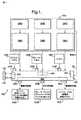
図1は、自律性乗物システム200が取り付けられる車両100のブロック図を示す。 FIG. 1 shows a block diagram of a
この図が、単純化されており、乗物の全ての構成要素を示してはおらず、自律システム200が関係のあるものに焦点を合わせていることが認識されるだろう。It will be appreciated that this diagram has been simplified and does not show all the components of the vehicle, and that the
本例における車両は地上用乗物であって、したがって牽引用1組の車輪(図示せず)のようなタイプの車両において一般に見られる構成要素を含んでいる。しかし、他のタイプの車両で本明細書において記述されているシステムが実行され得ることが理解されるだろう。The vehicle in this example is a ground vehicle and thus includes components commonly found in types of vehicles such as a set of tow wheels (not shown). However, it will be understood that the systems described herein may be implemented with other types of vehicles.
乗物100は、乗物の移動を実行するための様々な構成要素を含んでいる。本例においては、これらは、(エンジンの回転を始動させる)エンジン制御装置(ECU)102A、(ブレーキディスクにブレーキパットをあてる)ブレーキ・キャリパー102B、および(車両の前輪を回転させる)ハンドル・コラムを102C含んでいる。これらの移動構成要素があくまで典型的なものであり、また、空中または水中を移動するように構成された車両に適するもの(例えばスラスタ、かじ)を含めて変形体が可能であることが認識されるだろう。 The
上記の移動構成要素を制御するための人間により操作されるコントローラは、車両が自律システム200ではなくドライバーよって制御される際の使用のために設けられている。本例においては、アクセル・ペダル104A、ブレーキ・ペダル104B、およびハンドル104Cは、ECU102A、ブレーキ・キャリパー102B、およびハンドル・コラムを102Cそれぞれ制御する。やはり、これらのコントローラがあくまで典型的なものであり、他のタイプ、例えばジョイスティックが設けられ得ることが認識されるだろう。 A human-operated controller for controlling the moving components described above is provided for use when the vehicle is controlled by a driver rather than the
他の従来の地上用乗物でのように、ハンドル104Cは操縦コラム102Cによって前輪に機械的に接続されている。ハンドル104Cを回転することは、左または右に前輪を回転させる効果がある。アクセル要求は、人間のドライバーがアクセル・ペダル102Aを押し下げることによって発行される。アクセスペダル102Aは、アクセル位置を電子的値へと変換し、これをECU102Aへと渡す。次いで、ECU102Aは、(メーカーに特有な)適切なエンジン制御を実行してエンジン回転を増加させる。乗物のブレーキ動作は、ドライバーが、ブレーキ・ペダル102Bを押し下げ、ブレーキ・マスタ・シリンダ内に油圧(この油圧は油圧ホースによってブレーキ・キャリパー102Bに転送される)を生成し、ブレーキパットを押してブレーキディスクに接触させることよって達成される。 As in other conventional ground vehicles, the
車両100は、さらに人間が自律システム200(人間による操作されるコントローラ104を使用して操縦される代わりに)に車両の移動の制御権が移管されることを示すことを可能にするための少なくとも1つのコントローラ106を含んでいる。移管コントローラ106は、乗物のダッシュボードに配置されたボタンまたはスイッチなどであり得るが、他の仕組み、例えば電子音声制御または遠隔操作が使用され得ることが理解されるだろう。 The
例示的な乗物は、さらに、さらなる移管コントローラまたは「アーム」スイッチ108を含んでいる。その狙いは、人間のオペレータがまず第1移管コントローラ106を使用し、第1移管コントローラ106が自律システム200のためのコントロール・システム300に接続されるということである。第1移管コントローラ106からの信号を受け取ると、コントロール・システム300は、制御権を自律システム200に移管することが安全かどうかを後述のようにチェックするように動作する。安全であるならば、オペレータは、さらなる移管コントローラ108を用いて自律システム200を実際に制御/起動する。さらなる移管コントローラ108が随意的なものであり、また、適切であれば、第1移管コントローラ106だけを使用してコントロール・システム300を起動し、次いでコントロール・システム300が直接(このさらなる移管コントローラの使用なしで)自律システム200を起動してもよいことが理解されるだろう。 The exemplary vehicle further includes a further transfer controller or “arm”
自律システム200に移ると、これはいくつかの構成要素を含んでいる。これは、乗物100のアクセル、ハンドル、ブレーキ動作のパラメータを制御するように構成されるコンピュータを含んでいる。自律システムの既存の例は、イベントDARPAグランド・チャレンジに参加する乗物に取り付けられたものを含んでいる。ただし、これらの乗物は純粋に自律性なもので、人間のドライバーに切り替えるための設備は有していない。これらの自律システムのうちのいくつかは十分立証され、したがって、ここで詳細に記述される必要はない。自律システム200は、乗物100の移動構成要素102のための、移動構成要素102がコンピュータ・プロセッサ上で実行するコードによって制御されることを可能にするアクチュエータを含んでいる。コンピュータ・プロセッサはシステム200の一部である。 Moving to the
システム200は複数のモジュールを含み得る。それらの各々は、乗物のアクセル構成要素、ブレーキ構成要素、およびハンドル移動構成要素のうちの1つの制御を担う。しかしながら、システム要求は常にこのようになっているとは限らず、例えば、乗物の移動構成要素がブレーキの構成を含んでいない場合がそうであることが理解されるだろう。アクセル制御アクチュエータと接続しているコンピュータ・モジュール204Aは、ECU102Aにアナログ電気的出力を接続し、コンピュータがソフトウェアによって規定されたパーセンテージをモジュール206A内のアナログ変換ハードウェアによってECUにおいてアナログ値へと変換することによって、実現されることが可能である。ブレーキ動作制御モジュール204Bは、ブレーキ油圧機内に電気調水弁を設置し、ブレーキ・キャリパー102Bにおいてブレーキ動作コントロール・アクチュエータ206Bからのアナログ電気信号を油圧に変換することによって実行されることが可能である。このブレーキ動作コントローラは、前輪と後輪との間のブレーキ動作プロファイルを調整して乗物の牽引を管理し、ブレーキ動作コントローラがシステム・コンピュータから全体的なブレーキ動作パーセンテージを表わすアナログ値を受け取る。
ハンドル制御は、ハンドル104Cとハンドル・ラックの間でハンドル・コラム102のC上にサーボモータを設置することによって実行され得る。乗物の車輪の位置を表わすアナログ電気信号は、コンピュータ・モジュールから204C出力される。また、これらは、ハンドル制御アクチュエータ206Cによってハンドル・モータの位置へと解釈される。そして、ハンドル・モータは、ハンドル・コントローラからハンドル・モータ206Cに渡されたアナログ電気信号によって回転させられる。 Handle control can be performed by installing a servo motor on C of the handle column 102 between the
自律システム200の起動および動作停止を制御するためのシステム300は、自律システム200のアクチュエータ構成要素206A〜206Cに接続されている。また、多くの電気的リレー308を使用して、移動コマンドが人間により操作されるコントローラ104および自律システム200のコンピュータの両方から同時に送信されることが不能になるようにする。コントロール・システム300は、乗物の移管コントローラ/スイッチ106および108と通信可能な入出力構成要素302を含んでいる。コントロール・システムは、さらにプロセッサ/メモリ304および自律システム200から状態信号を受け取るための入力構成要素301を含んでいる。さらに、リレー308に接続されている共通の動作ライン306がコントロール・システムに含まれている。コントロール・システム300は、人間によって操作される1組のコントローラ104A〜104Cに接続されているスイッチ310A〜310Cをさらに含んでいる。 A
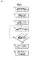
図2を参照すると、人間のオペレータから自律システム200へ乗物の移動の制御権を移管することに関与するステップが示されている。ステップ20において、乗物100は「自動車モード」である、つまり、人間のドライバーがコントローラ104を使用して乗物の移動を指揮する。ステップ21において、(ドライバーかもしれないし、そうでないかもしれない)人間のオペレータは、自律システム200が起動されるということを決定し(あるいは何らかの方法、例えばコンピュータ制御表示装置上のプロンプトによって通知されるかもしれない)、また自律システム200への電力のスイッチを(まだオンでない場合)オンする。ステップ22において、オペレータは、第1移管スイッチ106を引くことによって、自律システム200を起動する要望があることをコントロール・システム300に示す。ステップ23において、オペレータは、さらなる(「アーム」)移管コントローラ108を押して、自分が、自律システム200が乗物100の移動の制御権を引き継ぐのに対する準備ができていることを示す。 Referring to FIG. 2, the steps involved in transferring control of vehicle movement from a human operator to the
コントロール・システム300が第1スイッチ106およびさらなるスイッチ108が引かれたという信号を入力構成要素302を介して受け取ると、ステップ24において、プロセッサ/メモリ304は、信号が入力構成要素301で受け取られているかをチェックするコードを実行する。この信号は、乗物の制御権を引き継ぐための準備完了状態にある表示として自律システム200によって生成される。この信号はプロセッサによる命令で生成されるかもしれない。この信号は多くの形態を取り得る。例えば、この信号は、プロセッサに接続されたディジタル/アナログ変換ボードに渡される電気信号であり得る。そして、このボードは、「高電圧」状態としてのアナログ信号を出力することができる。そのような信号が使用されてリレーを起動することができる。あるいは、純粋にディジタル信号が使用されることが可能である。 When
信号が受け取られていない場合(あるいは、自律システム200が起動される準備ができていないことを示す信号が301で受け取られている場合)、このことは、自律システム200が乗物の制御権を引き継ぐ準備ができていないことを示す。この場合、コントロール・システムはステップ23に戻り、この時点で、オペレータは自律システムを起動することを試みるために再びさらなる移管スイッチ108を引かなければならない。 If no signal is received (or if a signal is received at 301 indicating that the
したがって、オペレータが自律システム200の準備ができる前にさらなるスイッチ108を押し下げることによって、自律システムを起動することはできないだろう。Thus, it would not be possible to activate the autonomous system by depressing a
他方、自律システム200の準備ができていることを示す信号201がステップ23で受け取られている場合、制御はステップ25に進み、そこで、自律システムのモジュールは、移動構成要素102のリレー/アクチュエータ308に従事することが可能にされる。ドライバーに、信号が(例えば、アーム・ボタン108を点灯して)与えられて、乗物が自律モードにあることを示すことができる。この時点において、コントロール・システム300はリレー308の起動コイルに電力を印加する。リレー308Aは、この自律モードへの切り替えの際に(乗物が「自動車」モードである場合のアクセル・ペダル104Aからの出力に代えて)コンピュータ・モジュール204Aの出力から入力を受け取るようにECU102Aを切り替える。リレー308Bが使用されて自律モードへの乗物の切り替えの際にブレーキ動作制御アクチュエータ206Cに電力を印加する。したがって、乗物が自動車モードである場合、ブレーキ動作コントローラは全く電力を有さない。リレー308Cが使用されて、自律モードにある時、ハンドル・コラム102Cに付けられたハンドル制御アクチュエータ206Cに電力を印加する。したがって、乗物が自動車モードである場合、ハンドル・コントローラは全く電力を有さない。共通の動作ライン306を介してリレー308をすべて接続しているということは、全てのリレーが実質的に同時に起動することを意味する。 On the other hand, if a
図3は、自律システム200から人間のオペレータ(すなわち自律モードから自動車モードへ)への乗物の移動の制御権を移管することに関与するステップを示す。そのような動作停止サブシステムは、上記のような起動サブシステムを有する乗物に随意的に設置され得る。ステップ30において、乗物は自律モードにある。また、自動車モードへの乗物の切り替えは、ステップ32A〜32Cのうちのいずれかの出来事の1つ以上に起因し得る。例えば、ステップ32Aにおいて、ドライバーはブレーキ・ペダル104Bを押し下げる。このことは、スイッチ310Bの状態を変化させる。コントロール・システム300は、この変更を示す信号を受け取る。そして、ステップ34において、自律システム200のアクチュエータが解放される(ステップ36で乗物が再び自動車モードであることとして示されている)。すなわち、リレー308Aは、アクセル・ペダル104Aから入力を受け取るようにECU102Aを切り替える。リレー308Bはブレーキ動作制御権アクチュエータ206Bから電力を取り去る。また、リレー308Cはハンドル・コラム102Cに取り付けられたハンドル制御アクチュエータ206Cから電力を取り去る。やはり、共通の動作ライン306は、これらの全てのリレーを実質的に同時にオフさせる。同様のやり方で、これらの動作停止ステップは、ドライバーがアクセル・ペダル104Aを押すこと(310Aの状態を切り替えることにつながる)、またはドライバーがハンドル104Cを回転させること(310Cの状態を切り替わることにつながる)に起因し得る。代替的な実施形態では、動作停止スイッチは、スイッチ310に加えてあるいはこれに代えて、人間のオペレータによる直接制御のために乗物内に(例えば、ダッシュボードに取り付けられて)配置されることが可能である。 FIG. 3 illustrates the steps involved in transferring control of vehicle movement from the
このように、コントロール・システム300は、何らかのペダル/ハンドルを押すと人間のドライバーに乗物の制御権を返すように設計されている。ペダル/ハンドルの解放に際して、人間のオペレータが図2を参照して上に記述されるような自律システム200に再び制御権を移管するまで、アクチュエータ・リレーは非動作状態のままである。 Thus, the
Claims (12)
Translated fromJapanese(a)
(i)自律性乗物システムが起動されることを示す起動信号を受け取るように構成されている入力装置と、
(ii)前記入力装置による前記起動信号の受信の際に、前記自律性乗物システムが起動されるための準備完了状態にあるかどうかチェックするように構成されている検査装置と、
(iii)前記自律性乗物システムが準備完了状態にあることを前記検査装置によって行なわれたチェックが示す場合のみ、前記自律性乗物システムを起動するように構成されている起動装置と、
を含む制御権移動システムと、
および/または(b)
スイッチがオンされると前記自律性乗物システムを前記乗物の移動の制御から動作停止するように構成されている少なくとも1つの動作停止スイッチを含む動作停止サブシステムと、
を含むシステム。A system adapted to transfer control of vehicle movement to an autonomous vehicle system and / or to move an autonomous vehicle system,
(A)
(I) an input device configured to receive an activation signal indicating that the autonomous vehicle system is activated;
(Ii) upon receipt of the activation signal by the input device, an inspection device configured to check whether the autonomous vehicle system is in a ready state for activation;
(Iii) an activation device configured to activate the autonomous vehicle system only if a check performed by the inspection device indicates that the autonomous vehicle system is in a ready state;
A control transfer system including:
And / or (b)
An outage subsystem comprising at least one deactivation switch configured to deactivate the autonomous vehicle system from controlling the movement of the vehicle when switched on;
Including system.
自律性乗物システムが起動されることを示す起動信号を受け取り、
前記起動信号の受信の際に、前記自律性乗物システムが起動されるための準備完了状態にあるかを調べ、
前記自律性乗物システムが準備完了状態にあることを前記検査装置によって行なわれたチェックが示す場合のみ、前記自律性乗物システムを起動する、
ことを含み、
および/または
スイッチがオンされると前記自律性乗物システムを前記乗物の操作から動作停止するように構成されている少なくとも1つの動作停止スイッチから信号を受け取ること、
を含む方法。A method for controlling an autonomous vehicle system comprising:
Receiving an activation signal indicating that the autonomous vehicle system is activated;
Upon receipt of the activation signal, check whether the autonomous vehicle system is ready to be activated,
Activating the autonomous vehicle system only if a check made by the inspection device indicates that the autonomous vehicle system is in a ready state;
Including
And / or receiving a signal from at least one deactivation switch configured to deactivate the autonomous vehicle system from operation of the vehicle when the switch is turned on;
Including methods.
Applications Claiming Priority (3)
| Application Number | Priority Date | Filing Date | Title |
|---|---|---|---|
| EP06270099 | 2006-12-11 | ||
| GB0624610AGB0624610D0 (en) | 2006-12-11 | 2006-12-11 | Controlling an autonomous vehicle system |
| PCT/GB2007/050740WO2008072007A2 (en) | 2006-12-11 | 2007-12-05 | Controlling an autonomous vehicle system |
Publications (1)
| Publication Number | Publication Date |
|---|---|
| JP2010512592Atrue JP2010512592A (en) | 2010-04-22 |
Family
ID=39512143
Family Applications (1)
| Application Number | Title | Priority Date | Filing Date |
|---|---|---|---|
| JP2009540873APendingJP2010512592A (en) | 2006-12-11 | 2007-12-05 | Control of autonomous vehicle systems |
Country Status (5)
| Country | Link |
|---|---|
| US (1) | US20100179715A1 (en) |
| EP (1) | EP2113097A2 (en) |
| JP (1) | JP2010512592A (en) |
| AU (1) | AU2007331292A1 (en) |
| WO (1) | WO2008072007A2 (en) |
Cited By (6)
| Publication number | Priority date | Publication date | Assignee | Title |
|---|---|---|---|---|
| KR20140136791A (en)* | 2013-05-21 | 2014-12-01 | 삼성테크윈 주식회사 | Method for generating path plan of mobile robot |
| JP2016504232A (en)* | 2012-11-30 | 2016-02-12 | グーグル インコーポレイテッド | Application and cancellation of autonomous driving |
| CN105984485A (en)* | 2015-03-23 | 2016-10-05 | 丰田自动车株式会社 | Autonomous driving device |
| US9519287B1 (en) | 2010-04-28 | 2016-12-13 | Google Inc. | User interface for displaying internal state of autonomous driving system |
| US9582907B1 (en) | 2010-04-28 | 2017-02-28 | Google Inc. | User interface for displaying internal state of autonomous driving system |
| US10449970B2 (en) | 2016-10-14 | 2019-10-22 | Toyota Jidosha Kabushiki Kaisha | Vehicle control system |
Families Citing this family (24)
| Publication number | Priority date | Publication date | Assignee | Title |
|---|---|---|---|---|
| US8509982B2 (en) | 2010-10-05 | 2013-08-13 | Google Inc. | Zone driving |
| US20150094898A1 (en)* | 2013-10-01 | 2015-04-02 | Ford Global Technologies, Llc | Vehicle autonomous mode deactivation |
| US20150100191A1 (en)* | 2013-10-09 | 2015-04-09 | Ford Global Technologies, Llc | Monitoring autonomous vehicle steering |
| US9650051B2 (en)* | 2013-12-22 | 2017-05-16 | Lytx, Inc. | Autonomous driving comparison and evaluation |
| US9428183B2 (en) | 2014-07-31 | 2016-08-30 | Toyota Motor Engineering & Manufacturing North America, Inc. | Self-explaining autonomous vehicle |
| US9321461B1 (en) | 2014-08-29 | 2016-04-26 | Google Inc. | Change detection using curve alignment |
| US9248834B1 (en) | 2014-10-02 | 2016-02-02 | Google Inc. | Predicting trajectories of objects based on contextual information |
| JP6304086B2 (en)* | 2015-03-23 | 2018-04-04 | トヨタ自動車株式会社 | Automatic driving device |
| EP3091411B1 (en)* | 2015-05-05 | 2020-02-19 | Volvo Car Corporation | Vehicle system, vehicle comprising a vehicle system and method for allowing transition from an autonomous driving mode |
| JP2017001597A (en) | 2015-06-15 | 2017-01-05 | トヨタ自動車株式会社 | Automatic driving device |
| JP6451537B2 (en)* | 2015-07-21 | 2019-01-16 | 株式会社デンソー | Driving support control device |
| US10099705B2 (en)* | 2015-08-31 | 2018-10-16 | Uber Technologies, Inc. | Control system for autonomous-capable vehicles |
| EP3356899B1 (en) | 2015-09-28 | 2021-12-29 | Uatc, Llc | Method of operating an autonomous vehicle having independent auxiliary control unit |
| US9580080B1 (en)* | 2016-03-15 | 2017-02-28 | Uber Technologies, Inc. | Drive-by-wire control system |
| US10279825B2 (en) | 2017-01-10 | 2019-05-07 | General Electric Company | Transfer of vehicle control system and method |
| JP6497353B2 (en)* | 2016-04-28 | 2019-04-10 | トヨタ自動車株式会社 | Automatic operation control device |
| US10059346B2 (en)* | 2016-06-07 | 2018-08-28 | Ford Global Technologies, Llc | Driver competency during autonomous handoff |
| JP6481670B2 (en) | 2016-09-12 | 2019-03-13 | トヨタ自動車株式会社 | Automated driving system |
| US10661764B1 (en) | 2017-03-28 | 2020-05-26 | Apple Inc. | Braking system control state transitions |
| JP6565988B2 (en)* | 2017-08-25 | 2019-08-28 | トヨタ自動車株式会社 | Automatic driving device |
| US10525951B2 (en)* | 2017-12-08 | 2020-01-07 | Robert Bosch Gmbh | Vehicle braking system and method of operating the same |
| WO2020191724A1 (en)* | 2019-03-28 | 2020-10-01 | 深圳市大疆创新科技有限公司 | Vehicle control system and vehicle |
| US11772671B2 (en)* | 2019-06-03 | 2023-10-03 | Toyota Research Institute, Inc. | Systems and methods for predicting control handback |
| US11912302B2 (en)* | 2020-12-21 | 2024-02-27 | Zoox, Inc. | Autonomous control engagement |
Citations (9)
| Publication number | Priority date | Publication date | Assignee | Title |
|---|---|---|---|---|
| JPS63154436A (en)* | 1986-12-19 | 1988-06-27 | Shin Caterpillar Mitsubishi Ltd | Air system for vehicle running control |
| JPH0455130A (en)* | 1990-06-20 | 1992-02-21 | Nec Corp | Automobile maneuvering control system |
| JPH06125610A (en)* | 1991-10-08 | 1994-05-10 | Yanmar Agricult Equip Co Ltd | Remote control signal processing device for autonomous vehicle |
| JPH06298108A (en)* | 1993-04-12 | 1994-10-25 | Aisin Seiki Co Ltd | Automatic steering device for vehicle |
| JPH0719059U (en)* | 1993-09-17 | 1995-04-04 | ヤンマー農機株式会社 | Electromagnetic induction type autonomous vehicle |
| JPH07117515A (en)* | 1993-10-20 | 1995-05-09 | Ishikawajima Shibaura Mach Co Ltd | Safety device of work vehicle for agriculture |
| JPH09128048A (en)* | 1995-10-31 | 1997-05-16 | Sanyo Electric Co Ltd | Guided golf cart |
| JPH11278093A (en)* | 1998-03-27 | 1999-10-12 | Nissan Motor Co Ltd | Constant-speed cruise control system for vehicles |
| JP2003077100A (en)* | 2001-09-03 | 2003-03-14 | Denso Corp | Anomaly detection system, automatic operation system, and anomaly detection method |
Family Cites Families (17)
| Publication number | Priority date | Publication date | Assignee | Title |
|---|---|---|---|---|
| US2960284A (en)* | 1957-01-11 | 1960-11-15 | Honeywell Regulator Co | Automatic control apparatus for aircraft |
| US3051137A (en)* | 1959-09-30 | 1962-08-28 | Honeywell Regulator Co | Control apparatus |
| US3386689A (en)* | 1967-02-06 | 1968-06-04 | Sperry Rand Corp | Aircraft autopilot with control wheel steering |
| FR2660454B1 (en)* | 1990-03-27 | 1996-08-09 | Commissariat Energie Atomique | METHOD FOR DRIVING A VEHICLE SUCH AS A WHEELCHAIR FOR A PERSON WITH A DISABILITY. |
| US5489830A (en)* | 1994-09-09 | 1996-02-06 | Mcdonnell Douglas Corporation | Control system with loadfeel and backdrive |
| JP3171119B2 (en)* | 1995-12-04 | 2001-05-28 | トヨタ自動車株式会社 | Automatic driving control device for vehicles |
| JP3239727B2 (en)* | 1995-12-05 | 2001-12-17 | トヨタ自動車株式会社 | Automatic driving control device for vehicles |
| JP3097542B2 (en)* | 1996-02-05 | 2000-10-10 | トヨタ自動車株式会社 | Automatic steering device |
| JPH1031799A (en)* | 1996-07-15 | 1998-02-03 | Toyota Motor Corp | Automatic driving control device |
| US6275754B1 (en)* | 1996-10-09 | 2001-08-14 | Honda Giken Kogyo Kabushiki Kaisha | Automatic steering system for vehicle |
| US6236916B1 (en)* | 1999-03-29 | 2001-05-22 | Caterpillar Inc. | Autoguidance system and method for an agricultural machine |
| US7366595B1 (en)* | 1999-06-25 | 2008-04-29 | Seiko Epson Corporation | Vehicle drive assist system |
| JP3498910B2 (en)* | 2000-09-05 | 2004-02-23 | 日産自動車株式会社 | Lane tracking controller |
| DE10155096A1 (en)* | 2001-11-09 | 2003-05-22 | Bosch Gmbh Robert | Speed controller with stop function |
| AU2002324984A1 (en)* | 2001-11-27 | 2003-06-10 | Honeywell International Inc. | Emergency flight control system |
| US8078338B2 (en)* | 2004-10-22 | 2011-12-13 | Irobot Corporation | System and method for behavior based control of an autonomous vehicle |
| AU2006306522B9 (en)* | 2005-10-21 | 2011-12-08 | Deere & Company | Networked multi-role robotic vehicle |
- 2007
- 2007-12-05AUAU2007331292Apatent/AU2007331292A1/ennot_activeAbandoned
- 2007-12-05WOPCT/GB2007/050740patent/WO2008072007A2/enactiveApplication Filing
- 2007-12-05EPEP07824950Apatent/EP2113097A2/ennot_activeWithdrawn
- 2007-12-05JPJP2009540873Apatent/JP2010512592A/enactivePending
- 2007-12-05USUS12/092,176patent/US20100179715A1/ennot_activeAbandoned
Patent Citations (9)
| Publication number | Priority date | Publication date | Assignee | Title |
|---|---|---|---|---|
| JPS63154436A (en)* | 1986-12-19 | 1988-06-27 | Shin Caterpillar Mitsubishi Ltd | Air system for vehicle running control |
| JPH0455130A (en)* | 1990-06-20 | 1992-02-21 | Nec Corp | Automobile maneuvering control system |
| JPH06125610A (en)* | 1991-10-08 | 1994-05-10 | Yanmar Agricult Equip Co Ltd | Remote control signal processing device for autonomous vehicle |
| JPH06298108A (en)* | 1993-04-12 | 1994-10-25 | Aisin Seiki Co Ltd | Automatic steering device for vehicle |
| JPH0719059U (en)* | 1993-09-17 | 1995-04-04 | ヤンマー農機株式会社 | Electromagnetic induction type autonomous vehicle |
| JPH07117515A (en)* | 1993-10-20 | 1995-05-09 | Ishikawajima Shibaura Mach Co Ltd | Safety device of work vehicle for agriculture |
| JPH09128048A (en)* | 1995-10-31 | 1997-05-16 | Sanyo Electric Co Ltd | Guided golf cart |
| JPH11278093A (en)* | 1998-03-27 | 1999-10-12 | Nissan Motor Co Ltd | Constant-speed cruise control system for vehicles |
| JP2003077100A (en)* | 2001-09-03 | 2003-03-14 | Denso Corp | Anomaly detection system, automatic operation system, and anomaly detection method |
Cited By (22)
| Publication number | Priority date | Publication date | Assignee | Title |
|---|---|---|---|---|
| US10082789B1 (en) | 2010-04-28 | 2018-09-25 | Waymo Llc | User interface for displaying internal state of autonomous driving system |
| US10093324B1 (en) | 2010-04-28 | 2018-10-09 | Waymo Llc | User interface for displaying internal state of autonomous driving system |
| US10843708B1 (en) | 2010-04-28 | 2020-11-24 | Waymo Llc | User interface for displaying internal state of autonomous driving system |
| US10768619B1 (en) | 2010-04-28 | 2020-09-08 | Waymo Llc | User interface for displaying internal state of autonomous driving system |
| US10293838B1 (en) | 2010-04-28 | 2019-05-21 | Waymo Llc | User interface for displaying internal state of autonomous driving system |
| US9519287B1 (en) | 2010-04-28 | 2016-12-13 | Google Inc. | User interface for displaying internal state of autonomous driving system |
| US9582907B1 (en) | 2010-04-28 | 2017-02-28 | Google Inc. | User interface for displaying internal state of autonomous driving system |
| US10120379B1 (en) | 2010-04-28 | 2018-11-06 | Waymo Llc | User interface for displaying internal state of autonomous driving system |
| US9352752B2 (en) | 2012-11-30 | 2016-05-31 | Google Inc. | Engaging and disengaging for autonomous driving |
| US12168448B2 (en) | 2012-11-30 | 2024-12-17 | Waymo Llc | Engaging and disengaging for autonomous driving |
| JP2016504232A (en)* | 2012-11-30 | 2016-02-12 | グーグル インコーポレイテッド | Application and cancellation of autonomous driving |
| US10300926B2 (en) | 2012-11-30 | 2019-05-28 | Waymo Llc | Engaging and disengaging for autonomous driving |
| US10000216B2 (en) | 2012-11-30 | 2018-06-19 | Waymo Llc | Engaging and disengaging for autonomous driving |
| US9821818B2 (en) | 2012-11-30 | 2017-11-21 | Waymo Llc | Engaging and disengaging for autonomous driving |
| US11643099B2 (en) | 2012-11-30 | 2023-05-09 | Waymo Llc | Engaging and disengaging for autonomous driving |
| US9663117B2 (en) | 2012-11-30 | 2017-05-30 | Google Inc. | Engaging and disengaging for autonomous driving |
| US10864917B2 (en) | 2012-11-30 | 2020-12-15 | Waymo Llc | Engaging and disengaging for autonomous driving |
| US9511779B2 (en) | 2012-11-30 | 2016-12-06 | Google Inc. | Engaging and disengaging for autonomous driving |
| KR20140136791A (en)* | 2013-05-21 | 2014-12-01 | 삼성테크윈 주식회사 | Method for generating path plan of mobile robot |
| KR101912797B1 (en)* | 2013-05-21 | 2018-10-29 | 한화지상방산 주식회사 | Method for generating path plan of mobile robot |
| CN105984485A (en)* | 2015-03-23 | 2016-10-05 | 丰田自动车株式会社 | Autonomous driving device |
| US10449970B2 (en) | 2016-10-14 | 2019-10-22 | Toyota Jidosha Kabushiki Kaisha | Vehicle control system |
Also Published As
| Publication number | Publication date |
|---|---|
| US20100179715A1 (en) | 2010-07-15 |
| WO2008072007A3 (en) | 2009-09-11 |
| AU2007331292A1 (en) | 2008-06-19 |
| EP2113097A2 (en) | 2009-11-04 |
| WO2008072007A2 (en) | 2008-06-19 |
Similar Documents
| Publication | Publication Date | Title |
|---|---|---|
| JP2010512592A (en) | Control of autonomous vehicle systems | |
| US11124169B2 (en) | System comprising separate control units for the actuation units of an electric parking brake | |
| CN109843673B (en) | Motor vehicle system, control method, storage medium, and control apparatus system | |
| JP5465796B2 (en) | System and method for automatic brake function for aircraft electric brake system | |
| JP5346813B2 (en) | Brake interlock for aircraft electric brake system | |
| JP6408585B2 (en) | Driving assistance system with improved fail safety and usability | |
| JP6488016B2 (en) | Operation switch and parking brake control device | |
| KR102481911B1 (en) | Motor vehicle control unit for electric parking brake | |
| US9873414B2 (en) | Parking brake system for a vehicle | |
| US9002608B2 (en) | Electro-hydraulic brake-by-wire system and method | |
| US8874341B2 (en) | Electronic brake actuator brake-by-wire system and method | |
| CN110770099B (en) | Brake caliper for a vehicle comprising a brake control unit | |
| JP2010529917A5 (en) | ||
| KR101919320B1 (en) | Brake pedal operation device of autonomous driving control car | |
| CN109501785B (en) | vehicle controls | |
| US20090189441A1 (en) | Distributed electrical/electronic architectures for brake-by-wire brake systems | |
| CN105799682B (en) | Brake system and method for operating same | |
| JP6727705B2 (en) | Electric parking brake device | |
| CN114701472A (en) | Electric control brake system | |
| WO2023036644A1 (en) | Deceleration system | |
| CN115703505A (en) | Driver steering via steering wheel during differential braking | |
| JP5073139B2 (en) | Device and method for the operation of an automobile brake device depending on the driving situation | |
| US12427968B2 (en) | Electric parking brake control device | |
| JP2024006760A (en) | brake device | |
| CN117002456A (en) | Redundant control system for electromechanical brake |
Legal Events
| Date | Code | Title | Description |
|---|---|---|---|
| A131 | Notification of reasons for refusal | Free format text:JAPANESE INTERMEDIATE CODE: A131 Effective date:20110712 | |
| A601 | Written request for extension of time | Free format text:JAPANESE INTERMEDIATE CODE: A601 Effective date:20111011 | |
| A602 | Written permission of extension of time | Free format text:JAPANESE INTERMEDIATE CODE: A602 Effective date:20111018 | |
| A601 | Written request for extension of time | Free format text:JAPANESE INTERMEDIATE CODE: A601 Effective date:20111111 | |
| A602 | Written permission of extension of time | Free format text:JAPANESE INTERMEDIATE CODE: A602 Effective date:20111118 | |
| A601 | Written request for extension of time | Free format text:JAPANESE INTERMEDIATE CODE: A601 Effective date:20111209 | |
| A602 | Written permission of extension of time | Free format text:JAPANESE INTERMEDIATE CODE: A602 Effective date:20111216 | |
| A521 | Request for written amendment filed | Free format text:JAPANESE INTERMEDIATE CODE: A523 Effective date:20111228 | |
| A131 | Notification of reasons for refusal | Free format text:JAPANESE INTERMEDIATE CODE: A131 Effective date:20120529 | |
| A02 | Decision of refusal | Free format text:JAPANESE INTERMEDIATE CODE: A02 Effective date:20121106 |