JP2010510853A - Orthopedic implants and prostheses - Google Patents
Orthopedic implants and prosthesesDownload PDFInfo
- Publication number
- JP2010510853A JP2010510853AJP2009538796AJP2009538796AJP2010510853AJP 2010510853 AJP2010510853 AJP 2010510853AJP 2009538796 AJP2009538796 AJP 2009538796AJP 2009538796 AJP2009538796 AJP 2009538796AJP 2010510853 AJP2010510853 AJP 2010510853A
- Authority
- JP
- Japan
- Prior art keywords
- implant
- instrument
- holes
- vertebral body
- bone
- Prior art date
- Legal status (The legal status is an assumption and is not a legal conclusion. Google has not performed a legal analysis and makes no representation as to the accuracy of the status listed.)
- Withdrawn
Links
- 239000007943implantSubstances0.000titleclaimsabstractdescription208
- 230000000399orthopedic effectEffects0.000titledescription3
- 210000000988bone and boneAnatomy0.000claimsabstractdescription57
- 238000000034methodMethods0.000claimsabstractdescription10
- 239000000463materialSubstances0.000claimsdescription45
- 238000003780insertionMethods0.000claimsdescription18
- 230000037431insertionEffects0.000claimsdescription18
- 230000008878couplingEffects0.000claimsdescription11
- 238000010168coupling processMethods0.000claimsdescription11
- 238000005859coupling reactionMethods0.000claimsdescription11
- 230000033001locomotionEffects0.000claimsdescription9
- 238000004873anchoringMethods0.000claimsdescription8
- 239000004696Poly ether ether ketoneSubstances0.000claimsdescription7
- 239000012620biological materialSubstances0.000claimsdescription7
- 229920002530polyetherether ketonePolymers0.000claimsdescription7
- 230000000278osteoconductive effectEffects0.000claimsdescription6
- 230000002138osteoinductive effectEffects0.000claimsdescription5
- 229920000642polymerPolymers0.000claimsdescription5
- 239000000316bone substituteSubstances0.000claimsdescription4
- 239000002131composite materialSubstances0.000claimsdescription4
- 230000007935neutral effectEffects0.000claimsdescription4
- 208000007623LordosisDiseases0.000claimsdescription3
- 239000005312bioglassSubstances0.000claimsdescription2
- 229910010293ceramic materialInorganic materials0.000claimsdescription2
- 238000006243chemical reactionMethods0.000claimsdescription2
- 230000003247decreasing effectEffects0.000claimsdescription2
- 239000000203mixtureSubstances0.000claimsdescription2
- 230000004044responseEffects0.000claimsdescription2
- 230000001953sensory effectEffects0.000claimsdescription2
- 206010023509KyphosisDiseases0.000claims1
- 239000002639bone cementSubstances0.000claims1
- 239000003795chemical substances by applicationSubstances0.000claims1
- 230000002188osteogenic effectEffects0.000claims1
- 230000002441reversible effectEffects0.000claims1
- 230000008439repair processEffects0.000abstractdescription3
- 230000007246mechanismEffects0.000description13
- 238000013459approachMethods0.000description12
- 230000008468bone growthEffects0.000description9
- 230000004927fusionEffects0.000description8
- 230000008901benefitEffects0.000description7
- 230000015572biosynthetic processEffects0.000description6
- 238000013461designMethods0.000description5
- 239000002184metalSubstances0.000description5
- 229910052751metalInorganic materials0.000description5
- 230000002093peripheral effectEffects0.000description5
- 230000035882stressEffects0.000description5
- 208000014674injuryDiseases0.000description4
- 210000000056organAnatomy0.000description4
- 208000013201Stress fractureDiseases0.000description3
- 230000006870functionEffects0.000description3
- 230000014759maintenance of locationEffects0.000description3
- 239000011148porous materialSubstances0.000description3
- 230000002265preventionEffects0.000description3
- 230000006641stabilisationEffects0.000description3
- 238000011105stabilizationMethods0.000description3
- 206010028980NeoplasmDiseases0.000description2
- 208000027418Wounds and injuryDiseases0.000description2
- 230000009471actionEffects0.000description2
- 235000021028berryNutrition0.000description2
- 230000006378damageEffects0.000description2
- 239000000835fiberSubstances0.000description2
- 208000015181infectious diseaseDiseases0.000description2
- 150000002739metalsChemical class0.000description2
- 235000015097nutrientsNutrition0.000description2
- 229920000728polyesterPolymers0.000description2
- 238000001356surgical procedureMethods0.000description2
- 210000001519tissueAnatomy0.000description2
- 230000008733traumaEffects0.000description2
- 208000023275Autoimmune diseaseDiseases0.000description1
- 208000010392Bone FracturesDiseases0.000description1
- 102000008186CollagenHuman genes0.000description1
- 108010035532CollagenProteins0.000description1
- 206010017076FractureDiseases0.000description1
- 206010061218InflammationDiseases0.000description1
- 230000002745absorbentEffects0.000description1
- 239000002250absorbentSubstances0.000description1
- 238000010521absorption reactionMethods0.000description1
- 239000000853adhesiveSubstances0.000description1
- 230000001070adhesive effectEffects0.000description1
- 230000032683agingEffects0.000description1
- 230000033115angiogenesisEffects0.000description1
- 239000000560biocompatible materialSubstances0.000description1
- 239000008280bloodSubstances0.000description1
- 210000004369bloodAnatomy0.000description1
- 230000036770blood supplyEffects0.000description1
- 210000001124body fluidAnatomy0.000description1
- 239000010839body fluidSubstances0.000description1
- 230000015556catabolic processEffects0.000description1
- 229920001436collagenPolymers0.000description1
- 239000000470constituentSubstances0.000description1
- 238000012937correctionMethods0.000description1
- 230000007850degenerationEffects0.000description1
- 238000006731degradation reactionMethods0.000description1
- 239000012634fragmentSubstances0.000description1
- 230000012010growthEffects0.000description1
- 239000007952growth promoterSubstances0.000description1
- 238000010438heat treatmentMethods0.000description1
- 238000002513implantationMethods0.000description1
- 230000006872improvementEffects0.000description1
- 230000004054inflammatory processEffects0.000description1
- 239000007788liquidSubstances0.000description1
- 239000011159matrix materialSubstances0.000description1
- 238000005259measurementMethods0.000description1
- 238000012986modificationMethods0.000description1
- 230000004048modificationEffects0.000description1
- 239000005365phosphate glassSubstances0.000description1
- 238000012545processingMethods0.000description1
- 230000035807sensationEffects0.000description1
- 238000004513sizingMethods0.000description1
- 239000007787solidSubstances0.000description1
- 230000004936stimulating effectEffects0.000description1
- 210000000115thoracic cavityAnatomy0.000description1
- 230000002792vascularEffects0.000description1
- 210000005166vasculatureAnatomy0.000description1
Images


Classifications
- A—HUMAN NECESSITIES
- A61—MEDICAL OR VETERINARY SCIENCE; HYGIENE
- A61B—DIAGNOSIS; SURGERY; IDENTIFICATION
- A61B17/00—Surgical instruments, devices or methods
- A61B17/56—Surgical instruments or methods for treatment of bones or joints; Devices specially adapted therefor
- A61B17/58—Surgical instruments or methods for treatment of bones or joints; Devices specially adapted therefor for osteosynthesis, e.g. bone plates, screws or setting implements
- A61B17/68—Internal fixation devices, including fasteners and spinal fixators, even if a part thereof projects from the skin
- A61B17/70—Spinal positioners or stabilisers, e.g. stabilisers comprising fluid filler in an implant
- A61B17/7059—Cortical plates
- A—HUMAN NECESSITIES
- A61—MEDICAL OR VETERINARY SCIENCE; HYGIENE
- A61B—DIAGNOSIS; SURGERY; IDENTIFICATION
- A61B17/00—Surgical instruments, devices or methods
- A61B17/56—Surgical instruments or methods for treatment of bones or joints; Devices specially adapted therefor
- A61B17/58—Surgical instruments or methods for treatment of bones or joints; Devices specially adapted therefor for osteosynthesis, e.g. bone plates, screws or setting implements
- A61B17/68—Internal fixation devices, including fasteners and spinal fixators, even if a part thereof projects from the skin
- A61B17/70—Spinal positioners or stabilisers, e.g. stabilisers comprising fluid filler in an implant
- A—HUMAN NECESSITIES
- A61—MEDICAL OR VETERINARY SCIENCE; HYGIENE
- A61B—DIAGNOSIS; SURGERY; IDENTIFICATION
- A61B17/00—Surgical instruments, devices or methods
- A61B17/56—Surgical instruments or methods for treatment of bones or joints; Devices specially adapted therefor
- A61B17/58—Surgical instruments or methods for treatment of bones or joints; Devices specially adapted therefor for osteosynthesis, e.g. bone plates, screws or setting implements
- A61B17/68—Internal fixation devices, including fasteners and spinal fixators, even if a part thereof projects from the skin
- A61B17/80—Cortical plates, i.e. bone plates; Instruments for holding or positioning cortical plates, or for compressing bones attached to cortical plates
- A61B17/8085—Cortical plates, i.e. bone plates; Instruments for holding or positioning cortical plates, or for compressing bones attached to cortical plates with pliable or malleable elements or having a mesh-like structure, e.g. small strips
- A—HUMAN NECESSITIES
- A61—MEDICAL OR VETERINARY SCIENCE; HYGIENE
- A61F—FILTERS IMPLANTABLE INTO BLOOD VESSELS; PROSTHESES; DEVICES PROVIDING PATENCY TO, OR PREVENTING COLLAPSING OF, TUBULAR STRUCTURES OF THE BODY, e.g. STENTS; ORTHOPAEDIC, NURSING OR CONTRACEPTIVE DEVICES; FOMENTATION; TREATMENT OR PROTECTION OF EYES OR EARS; BANDAGES, DRESSINGS OR ABSORBENT PADS; FIRST-AID KITS
- A61F2/00—Filters implantable into blood vessels; Prostheses, i.e. artificial substitutes or replacements for parts of the body; Appliances for connecting them with the body; Devices providing patency to, or preventing collapsing of, tubular structures of the body, e.g. stents
- A61F2/02—Prostheses implantable into the body
- A61F2/30—Joints
- A61F2/44—Joints for the spine, e.g. vertebrae, spinal discs
- A61F2/4455—Joints for the spine, e.g. vertebrae, spinal discs for the fusion of spinal bodies, e.g. intervertebral fusion of adjacent spinal bodies, e.g. fusion cages
- A—HUMAN NECESSITIES
- A61—MEDICAL OR VETERINARY SCIENCE; HYGIENE
- A61F—FILTERS IMPLANTABLE INTO BLOOD VESSELS; PROSTHESES; DEVICES PROVIDING PATENCY TO, OR PREVENTING COLLAPSING OF, TUBULAR STRUCTURES OF THE BODY, e.g. STENTS; ORTHOPAEDIC, NURSING OR CONTRACEPTIVE DEVICES; FOMENTATION; TREATMENT OR PROTECTION OF EYES OR EARS; BANDAGES, DRESSINGS OR ABSORBENT PADS; FIRST-AID KITS
- A61F2/00—Filters implantable into blood vessels; Prostheses, i.e. artificial substitutes or replacements for parts of the body; Appliances for connecting them with the body; Devices providing patency to, or preventing collapsing of, tubular structures of the body, e.g. stents
- A61F2/02—Prostheses implantable into the body
- A61F2/30—Joints
- A61F2/46—Special tools for implanting artificial joints
- A61F2/4603—Special tools for implanting artificial joints for insertion or extraction of endoprosthetic joints or of accessories thereof
- A61F2/4611—Special tools for implanting artificial joints for insertion or extraction of endoprosthetic joints or of accessories thereof of spinal prostheses
- A—HUMAN NECESSITIES
- A61—MEDICAL OR VETERINARY SCIENCE; HYGIENE
- A61B—DIAGNOSIS; SURGERY; IDENTIFICATION
- A61B17/00—Surgical instruments, devices or methods
- A61B17/56—Surgical instruments or methods for treatment of bones or joints; Devices specially adapted therefor
- A61B17/58—Surgical instruments or methods for treatment of bones or joints; Devices specially adapted therefor for osteosynthesis, e.g. bone plates, screws or setting implements
- A61B17/68—Internal fixation devices, including fasteners and spinal fixators, even if a part thereof projects from the skin
- A61B17/70—Spinal positioners or stabilisers, e.g. stabilisers comprising fluid filler in an implant
- A61B17/7001—Screws or hooks combined with longitudinal elements which do not contact vertebrae
- A61B17/7002—Longitudinal elements, e.g. rods
- A—HUMAN NECESSITIES
- A61—MEDICAL OR VETERINARY SCIENCE; HYGIENE
- A61F—FILTERS IMPLANTABLE INTO BLOOD VESSELS; PROSTHESES; DEVICES PROVIDING PATENCY TO, OR PREVENTING COLLAPSING OF, TUBULAR STRUCTURES OF THE BODY, e.g. STENTS; ORTHOPAEDIC, NURSING OR CONTRACEPTIVE DEVICES; FOMENTATION; TREATMENT OR PROTECTION OF EYES OR EARS; BANDAGES, DRESSINGS OR ABSORBENT PADS; FIRST-AID KITS
- A61F2/00—Filters implantable into blood vessels; Prostheses, i.e. artificial substitutes or replacements for parts of the body; Appliances for connecting them with the body; Devices providing patency to, or preventing collapsing of, tubular structures of the body, e.g. stents
- A61F2/02—Prostheses implantable into the body
- A61F2/28—Bones
- A61F2002/2835—Bone graft implants for filling a bony defect or an endoprosthesis cavity, e.g. by synthetic material or biological material
- A—HUMAN NECESSITIES
- A61—MEDICAL OR VETERINARY SCIENCE; HYGIENE
- A61F—FILTERS IMPLANTABLE INTO BLOOD VESSELS; PROSTHESES; DEVICES PROVIDING PATENCY TO, OR PREVENTING COLLAPSING OF, TUBULAR STRUCTURES OF THE BODY, e.g. STENTS; ORTHOPAEDIC, NURSING OR CONTRACEPTIVE DEVICES; FOMENTATION; TREATMENT OR PROTECTION OF EYES OR EARS; BANDAGES, DRESSINGS OR ABSORBENT PADS; FIRST-AID KITS
- A61F2/00—Filters implantable into blood vessels; Prostheses, i.e. artificial substitutes or replacements for parts of the body; Appliances for connecting them with the body; Devices providing patency to, or preventing collapsing of, tubular structures of the body, e.g. stents
- A61F2/02—Prostheses implantable into the body
- A61F2/30—Joints
- A61F2002/30001—Additional features of subject-matter classified in A61F2/28, A61F2/30 and subgroups thereof
- A61F2002/30003—Material related properties of the prosthesis or of a coating on the prosthesis
- A61F2002/3006—Properties of materials and coating materials
- A61F2002/30062—(bio)absorbable, biodegradable, bioerodable, (bio)resorbable, resorptive
- A—HUMAN NECESSITIES
- A61—MEDICAL OR VETERINARY SCIENCE; HYGIENE
- A61F—FILTERS IMPLANTABLE INTO BLOOD VESSELS; PROSTHESES; DEVICES PROVIDING PATENCY TO, OR PREVENTING COLLAPSING OF, TUBULAR STRUCTURES OF THE BODY, e.g. STENTS; ORTHOPAEDIC, NURSING OR CONTRACEPTIVE DEVICES; FOMENTATION; TREATMENT OR PROTECTION OF EYES OR EARS; BANDAGES, DRESSINGS OR ABSORBENT PADS; FIRST-AID KITS
- A61F2/00—Filters implantable into blood vessels; Prostheses, i.e. artificial substitutes or replacements for parts of the body; Appliances for connecting them with the body; Devices providing patency to, or preventing collapsing of, tubular structures of the body, e.g. stents
- A61F2/02—Prostheses implantable into the body
- A61F2/30—Joints
- A61F2002/30001—Additional features of subject-matter classified in A61F2/28, A61F2/30 and subgroups thereof
- A61F2002/30003—Material related properties of the prosthesis or of a coating on the prosthesis
- A61F2002/3006—Properties of materials and coating materials
- A61F2002/30092—Properties of materials and coating materials using shape memory or superelastic materials, e.g. nitinol
- A—HUMAN NECESSITIES
- A61—MEDICAL OR VETERINARY SCIENCE; HYGIENE
- A61F—FILTERS IMPLANTABLE INTO BLOOD VESSELS; PROSTHESES; DEVICES PROVIDING PATENCY TO, OR PREVENTING COLLAPSING OF, TUBULAR STRUCTURES OF THE BODY, e.g. STENTS; ORTHOPAEDIC, NURSING OR CONTRACEPTIVE DEVICES; FOMENTATION; TREATMENT OR PROTECTION OF EYES OR EARS; BANDAGES, DRESSINGS OR ABSORBENT PADS; FIRST-AID KITS
- A61F2/00—Filters implantable into blood vessels; Prostheses, i.e. artificial substitutes or replacements for parts of the body; Appliances for connecting them with the body; Devices providing patency to, or preventing collapsing of, tubular structures of the body, e.g. stents
- A61F2/02—Prostheses implantable into the body
- A61F2/30—Joints
- A61F2002/30001—Additional features of subject-matter classified in A61F2/28, A61F2/30 and subgroups thereof
- A61F2002/30108—Shapes
- A61F2002/3011—Cross-sections or two-dimensional shapes
- A61F2002/30112—Rounded shapes, e.g. with rounded corners
- A61F2002/30131—Rounded shapes, e.g. with rounded corners horseshoe- or crescent- or C-shaped or U-shaped
- A—HUMAN NECESSITIES
- A61—MEDICAL OR VETERINARY SCIENCE; HYGIENE
- A61F—FILTERS IMPLANTABLE INTO BLOOD VESSELS; PROSTHESES; DEVICES PROVIDING PATENCY TO, OR PREVENTING COLLAPSING OF, TUBULAR STRUCTURES OF THE BODY, e.g. STENTS; ORTHOPAEDIC, NURSING OR CONTRACEPTIVE DEVICES; FOMENTATION; TREATMENT OR PROTECTION OF EYES OR EARS; BANDAGES, DRESSINGS OR ABSORBENT PADS; FIRST-AID KITS
- A61F2/00—Filters implantable into blood vessels; Prostheses, i.e. artificial substitutes or replacements for parts of the body; Appliances for connecting them with the body; Devices providing patency to, or preventing collapsing of, tubular structures of the body, e.g. stents
- A61F2/02—Prostheses implantable into the body
- A61F2/30—Joints
- A61F2002/30001—Additional features of subject-matter classified in A61F2/28, A61F2/30 and subgroups thereof
- A61F2002/30316—The prosthesis having different structural features at different locations within the same prosthesis; Connections between prosthetic parts; Special structural features of bone or joint prostheses not otherwise provided for
- A61F2002/30329—Connections or couplings between prosthetic parts, e.g. between modular parts; Connecting elements
- A61F2002/30433—Connections or couplings between prosthetic parts, e.g. between modular parts; Connecting elements using additional screws, bolts, dowels, rivets or washers e.g. connecting screws
- A—HUMAN NECESSITIES
- A61—MEDICAL OR VETERINARY SCIENCE; HYGIENE
- A61F—FILTERS IMPLANTABLE INTO BLOOD VESSELS; PROSTHESES; DEVICES PROVIDING PATENCY TO, OR PREVENTING COLLAPSING OF, TUBULAR STRUCTURES OF THE BODY, e.g. STENTS; ORTHOPAEDIC, NURSING OR CONTRACEPTIVE DEVICES; FOMENTATION; TREATMENT OR PROTECTION OF EYES OR EARS; BANDAGES, DRESSINGS OR ABSORBENT PADS; FIRST-AID KITS
- A61F2/00—Filters implantable into blood vessels; Prostheses, i.e. artificial substitutes or replacements for parts of the body; Appliances for connecting them with the body; Devices providing patency to, or preventing collapsing of, tubular structures of the body, e.g. stents
- A61F2/02—Prostheses implantable into the body
- A61F2/30—Joints
- A61F2002/30001—Additional features of subject-matter classified in A61F2/28, A61F2/30 and subgroups thereof
- A61F2002/30316—The prosthesis having different structural features at different locations within the same prosthesis; Connections between prosthetic parts; Special structural features of bone or joint prostheses not otherwise provided for
- A61F2002/30329—Connections or couplings between prosthetic parts, e.g. between modular parts; Connecting elements
- A61F2002/30459—Connections or couplings between prosthetic parts, e.g. between modular parts; Connecting elements stapled
- A—HUMAN NECESSITIES
- A61—MEDICAL OR VETERINARY SCIENCE; HYGIENE
- A61F—FILTERS IMPLANTABLE INTO BLOOD VESSELS; PROSTHESES; DEVICES PROVIDING PATENCY TO, OR PREVENTING COLLAPSING OF, TUBULAR STRUCTURES OF THE BODY, e.g. STENTS; ORTHOPAEDIC, NURSING OR CONTRACEPTIVE DEVICES; FOMENTATION; TREATMENT OR PROTECTION OF EYES OR EARS; BANDAGES, DRESSINGS OR ABSORBENT PADS; FIRST-AID KITS
- A61F2/00—Filters implantable into blood vessels; Prostheses, i.e. artificial substitutes or replacements for parts of the body; Appliances for connecting them with the body; Devices providing patency to, or preventing collapsing of, tubular structures of the body, e.g. stents
- A61F2/02—Prostheses implantable into the body
- A61F2/30—Joints
- A61F2002/30001—Additional features of subject-matter classified in A61F2/28, A61F2/30 and subgroups thereof
- A61F2002/30316—The prosthesis having different structural features at different locations within the same prosthesis; Connections between prosthetic parts; Special structural features of bone or joint prostheses not otherwise provided for
- A61F2002/30329—Connections or couplings between prosthetic parts, e.g. between modular parts; Connecting elements
- A61F2002/30471—Connections or couplings between prosthetic parts, e.g. between modular parts; Connecting elements connected by a hinged linkage mechanism, e.g. of the single-bar or multi-bar linkage type
- A—HUMAN NECESSITIES
- A61—MEDICAL OR VETERINARY SCIENCE; HYGIENE
- A61F—FILTERS IMPLANTABLE INTO BLOOD VESSELS; PROSTHESES; DEVICES PROVIDING PATENCY TO, OR PREVENTING COLLAPSING OF, TUBULAR STRUCTURES OF THE BODY, e.g. STENTS; ORTHOPAEDIC, NURSING OR CONTRACEPTIVE DEVICES; FOMENTATION; TREATMENT OR PROTECTION OF EYES OR EARS; BANDAGES, DRESSINGS OR ABSORBENT PADS; FIRST-AID KITS
- A61F2/00—Filters implantable into blood vessels; Prostheses, i.e. artificial substitutes or replacements for parts of the body; Appliances for connecting them with the body; Devices providing patency to, or preventing collapsing of, tubular structures of the body, e.g. stents
- A61F2/02—Prostheses implantable into the body
- A61F2/30—Joints
- A61F2002/30001—Additional features of subject-matter classified in A61F2/28, A61F2/30 and subgroups thereof
- A61F2002/30316—The prosthesis having different structural features at different locations within the same prosthesis; Connections between prosthetic parts; Special structural features of bone or joint prostheses not otherwise provided for
- A61F2002/30329—Connections or couplings between prosthetic parts, e.g. between modular parts; Connecting elements
- A61F2002/30476—Connections or couplings between prosthetic parts, e.g. between modular parts; Connecting elements locked by an additional locking mechanism
- A61F2002/30492—Connections or couplings between prosthetic parts, e.g. between modular parts; Connecting elements locked by an additional locking mechanism using a locking pin
- A—HUMAN NECESSITIES
- A61—MEDICAL OR VETERINARY SCIENCE; HYGIENE
- A61F—FILTERS IMPLANTABLE INTO BLOOD VESSELS; PROSTHESES; DEVICES PROVIDING PATENCY TO, OR PREVENTING COLLAPSING OF, TUBULAR STRUCTURES OF THE BODY, e.g. STENTS; ORTHOPAEDIC, NURSING OR CONTRACEPTIVE DEVICES; FOMENTATION; TREATMENT OR PROTECTION OF EYES OR EARS; BANDAGES, DRESSINGS OR ABSORBENT PADS; FIRST-AID KITS
- A61F2/00—Filters implantable into blood vessels; Prostheses, i.e. artificial substitutes or replacements for parts of the body; Appliances for connecting them with the body; Devices providing patency to, or preventing collapsing of, tubular structures of the body, e.g. stents
- A61F2/02—Prostheses implantable into the body
- A61F2/30—Joints
- A61F2002/30001—Additional features of subject-matter classified in A61F2/28, A61F2/30 and subgroups thereof
- A61F2002/30316—The prosthesis having different structural features at different locations within the same prosthesis; Connections between prosthetic parts; Special structural features of bone or joint prostheses not otherwise provided for
- A61F2002/30329—Connections or couplings between prosthetic parts, e.g. between modular parts; Connecting elements
- A61F2002/30476—Connections or couplings between prosthetic parts, e.g. between modular parts; Connecting elements locked by an additional locking mechanism
- A61F2002/305—Snap connection
- A—HUMAN NECESSITIES
- A61—MEDICAL OR VETERINARY SCIENCE; HYGIENE
- A61F—FILTERS IMPLANTABLE INTO BLOOD VESSELS; PROSTHESES; DEVICES PROVIDING PATENCY TO, OR PREVENTING COLLAPSING OF, TUBULAR STRUCTURES OF THE BODY, e.g. STENTS; ORTHOPAEDIC, NURSING OR CONTRACEPTIVE DEVICES; FOMENTATION; TREATMENT OR PROTECTION OF EYES OR EARS; BANDAGES, DRESSINGS OR ABSORBENT PADS; FIRST-AID KITS
- A61F2/00—Filters implantable into blood vessels; Prostheses, i.e. artificial substitutes or replacements for parts of the body; Appliances for connecting them with the body; Devices providing patency to, or preventing collapsing of, tubular structures of the body, e.g. stents
- A61F2/02—Prostheses implantable into the body
- A61F2/30—Joints
- A61F2002/30001—Additional features of subject-matter classified in A61F2/28, A61F2/30 and subgroups thereof
- A61F2002/30316—The prosthesis having different structural features at different locations within the same prosthesis; Connections between prosthetic parts; Special structural features of bone or joint prostheses not otherwise provided for
- A61F2002/30329—Connections or couplings between prosthetic parts, e.g. between modular parts; Connecting elements
- A61F2002/30476—Connections or couplings between prosthetic parts, e.g. between modular parts; Connecting elements locked by an additional locking mechanism
- A61F2002/30507—Connections or couplings between prosthetic parts, e.g. between modular parts; Connecting elements locked by an additional locking mechanism using a threaded locking member, e.g. a locking screw or a set screw
- A—HUMAN NECESSITIES
- A61—MEDICAL OR VETERINARY SCIENCE; HYGIENE
- A61F—FILTERS IMPLANTABLE INTO BLOOD VESSELS; PROSTHESES; DEVICES PROVIDING PATENCY TO, OR PREVENTING COLLAPSING OF, TUBULAR STRUCTURES OF THE BODY, e.g. STENTS; ORTHOPAEDIC, NURSING OR CONTRACEPTIVE DEVICES; FOMENTATION; TREATMENT OR PROTECTION OF EYES OR EARS; BANDAGES, DRESSINGS OR ABSORBENT PADS; FIRST-AID KITS
- A61F2/00—Filters implantable into blood vessels; Prostheses, i.e. artificial substitutes or replacements for parts of the body; Appliances for connecting them with the body; Devices providing patency to, or preventing collapsing of, tubular structures of the body, e.g. stents
- A61F2/02—Prostheses implantable into the body
- A61F2/30—Joints
- A61F2002/30001—Additional features of subject-matter classified in A61F2/28, A61F2/30 and subgroups thereof
- A61F2002/30316—The prosthesis having different structural features at different locations within the same prosthesis; Connections between prosthetic parts; Special structural features of bone or joint prostheses not otherwise provided for
- A61F2002/30535—Special structural features of bone or joint prostheses not otherwise provided for
- A61F2002/30537—Special structural features of bone or joint prostheses not otherwise provided for adjustable
- A61F2002/30538—Special structural features of bone or joint prostheses not otherwise provided for adjustable for adjusting angular orientation
- A—HUMAN NECESSITIES
- A61—MEDICAL OR VETERINARY SCIENCE; HYGIENE
- A61F—FILTERS IMPLANTABLE INTO BLOOD VESSELS; PROSTHESES; DEVICES PROVIDING PATENCY TO, OR PREVENTING COLLAPSING OF, TUBULAR STRUCTURES OF THE BODY, e.g. STENTS; ORTHOPAEDIC, NURSING OR CONTRACEPTIVE DEVICES; FOMENTATION; TREATMENT OR PROTECTION OF EYES OR EARS; BANDAGES, DRESSINGS OR ABSORBENT PADS; FIRST-AID KITS
- A61F2/00—Filters implantable into blood vessels; Prostheses, i.e. artificial substitutes or replacements for parts of the body; Appliances for connecting them with the body; Devices providing patency to, or preventing collapsing of, tubular structures of the body, e.g. stents
- A61F2/02—Prostheses implantable into the body
- A61F2/30—Joints
- A61F2002/30001—Additional features of subject-matter classified in A61F2/28, A61F2/30 and subgroups thereof
- A61F2002/30316—The prosthesis having different structural features at different locations within the same prosthesis; Connections between prosthetic parts; Special structural features of bone or joint prostheses not otherwise provided for
- A61F2002/30535—Special structural features of bone or joint prostheses not otherwise provided for
- A61F2002/30537—Special structural features of bone or joint prostheses not otherwise provided for adjustable
- A61F2002/3055—Special structural features of bone or joint prostheses not otherwise provided for adjustable for adjusting length
- A—HUMAN NECESSITIES
- A61—MEDICAL OR VETERINARY SCIENCE; HYGIENE
- A61F—FILTERS IMPLANTABLE INTO BLOOD VESSELS; PROSTHESES; DEVICES PROVIDING PATENCY TO, OR PREVENTING COLLAPSING OF, TUBULAR STRUCTURES OF THE BODY, e.g. STENTS; ORTHOPAEDIC, NURSING OR CONTRACEPTIVE DEVICES; FOMENTATION; TREATMENT OR PROTECTION OF EYES OR EARS; BANDAGES, DRESSINGS OR ABSORBENT PADS; FIRST-AID KITS
- A61F2/00—Filters implantable into blood vessels; Prostheses, i.e. artificial substitutes or replacements for parts of the body; Appliances for connecting them with the body; Devices providing patency to, or preventing collapsing of, tubular structures of the body, e.g. stents
- A61F2/02—Prostheses implantable into the body
- A61F2/30—Joints
- A61F2002/30001—Additional features of subject-matter classified in A61F2/28, A61F2/30 and subgroups thereof
- A61F2002/30316—The prosthesis having different structural features at different locations within the same prosthesis; Connections between prosthetic parts; Special structural features of bone or joint prostheses not otherwise provided for
- A61F2002/30535—Special structural features of bone or joint prostheses not otherwise provided for
- A61F2002/30576—Special structural features of bone or joint prostheses not otherwise provided for with extending fixation tabs
- A61F2002/30578—Special structural features of bone or joint prostheses not otherwise provided for with extending fixation tabs having apertures, e.g. for receiving fixation screws
- A—HUMAN NECESSITIES
- A61—MEDICAL OR VETERINARY SCIENCE; HYGIENE
- A61F—FILTERS IMPLANTABLE INTO BLOOD VESSELS; PROSTHESES; DEVICES PROVIDING PATENCY TO, OR PREVENTING COLLAPSING OF, TUBULAR STRUCTURES OF THE BODY, e.g. STENTS; ORTHOPAEDIC, NURSING OR CONTRACEPTIVE DEVICES; FOMENTATION; TREATMENT OR PROTECTION OF EYES OR EARS; BANDAGES, DRESSINGS OR ABSORBENT PADS; FIRST-AID KITS
- A61F2/00—Filters implantable into blood vessels; Prostheses, i.e. artificial substitutes or replacements for parts of the body; Appliances for connecting them with the body; Devices providing patency to, or preventing collapsing of, tubular structures of the body, e.g. stents
- A61F2/02—Prostheses implantable into the body
- A61F2/30—Joints
- A61F2002/30001—Additional features of subject-matter classified in A61F2/28, A61F2/30 and subgroups thereof
- A61F2002/30316—The prosthesis having different structural features at different locations within the same prosthesis; Connections between prosthetic parts; Special structural features of bone or joint prostheses not otherwise provided for
- A61F2002/30535—Special structural features of bone or joint prostheses not otherwise provided for
- A61F2002/30593—Special structural features of bone or joint prostheses not otherwise provided for hollow
- A—HUMAN NECESSITIES
- A61—MEDICAL OR VETERINARY SCIENCE; HYGIENE
- A61F—FILTERS IMPLANTABLE INTO BLOOD VESSELS; PROSTHESES; DEVICES PROVIDING PATENCY TO, OR PREVENTING COLLAPSING OF, TUBULAR STRUCTURES OF THE BODY, e.g. STENTS; ORTHOPAEDIC, NURSING OR CONTRACEPTIVE DEVICES; FOMENTATION; TREATMENT OR PROTECTION OF EYES OR EARS; BANDAGES, DRESSINGS OR ABSORBENT PADS; FIRST-AID KITS
- A61F2/00—Filters implantable into blood vessels; Prostheses, i.e. artificial substitutes or replacements for parts of the body; Appliances for connecting them with the body; Devices providing patency to, or preventing collapsing of, tubular structures of the body, e.g. stents
- A61F2/02—Prostheses implantable into the body
- A61F2/30—Joints
- A61F2002/30001—Additional features of subject-matter classified in A61F2/28, A61F2/30 and subgroups thereof
- A61F2002/30316—The prosthesis having different structural features at different locations within the same prosthesis; Connections between prosthetic parts; Special structural features of bone or joint prostheses not otherwise provided for
- A61F2002/30535—Special structural features of bone or joint prostheses not otherwise provided for
- A61F2002/30601—Special structural features of bone or joint prostheses not otherwise provided for telescopic
- A—HUMAN NECESSITIES
- A61—MEDICAL OR VETERINARY SCIENCE; HYGIENE
- A61F—FILTERS IMPLANTABLE INTO BLOOD VESSELS; PROSTHESES; DEVICES PROVIDING PATENCY TO, OR PREVENTING COLLAPSING OF, TUBULAR STRUCTURES OF THE BODY, e.g. STENTS; ORTHOPAEDIC, NURSING OR CONTRACEPTIVE DEVICES; FOMENTATION; TREATMENT OR PROTECTION OF EYES OR EARS; BANDAGES, DRESSINGS OR ABSORBENT PADS; FIRST-AID KITS
- A61F2/00—Filters implantable into blood vessels; Prostheses, i.e. artificial substitutes or replacements for parts of the body; Appliances for connecting them with the body; Devices providing patency to, or preventing collapsing of, tubular structures of the body, e.g. stents
- A61F2/02—Prostheses implantable into the body
- A61F2/30—Joints
- A61F2002/30001—Additional features of subject-matter classified in A61F2/28, A61F2/30 and subgroups thereof
- A61F2002/30316—The prosthesis having different structural features at different locations within the same prosthesis; Connections between prosthetic parts; Special structural features of bone or joint prostheses not otherwise provided for
- A61F2002/30535—Special structural features of bone or joint prostheses not otherwise provided for
- A61F2002/30604—Special structural features of bone or joint prostheses not otherwise provided for modular
- A—HUMAN NECESSITIES
- A61—MEDICAL OR VETERINARY SCIENCE; HYGIENE
- A61F—FILTERS IMPLANTABLE INTO BLOOD VESSELS; PROSTHESES; DEVICES PROVIDING PATENCY TO, OR PREVENTING COLLAPSING OF, TUBULAR STRUCTURES OF THE BODY, e.g. STENTS; ORTHOPAEDIC, NURSING OR CONTRACEPTIVE DEVICES; FOMENTATION; TREATMENT OR PROTECTION OF EYES OR EARS; BANDAGES, DRESSINGS OR ABSORBENT PADS; FIRST-AID KITS
- A61F2/00—Filters implantable into blood vessels; Prostheses, i.e. artificial substitutes or replacements for parts of the body; Appliances for connecting them with the body; Devices providing patency to, or preventing collapsing of, tubular structures of the body, e.g. stents
- A61F2/02—Prostheses implantable into the body
- A61F2/30—Joints
- A61F2/30767—Special external or bone-contacting surface, e.g. coating for improving bone ingrowth
- A61F2/30771—Special external or bone-contacting surface, e.g. coating for improving bone ingrowth applied in original prostheses, e.g. holes or grooves
- A61F2002/30841—Sharp anchoring protrusions for impaction into the bone, e.g. sharp pins, spikes
- A—HUMAN NECESSITIES
- A61—MEDICAL OR VETERINARY SCIENCE; HYGIENE
- A61F—FILTERS IMPLANTABLE INTO BLOOD VESSELS; PROSTHESES; DEVICES PROVIDING PATENCY TO, OR PREVENTING COLLAPSING OF, TUBULAR STRUCTURES OF THE BODY, e.g. STENTS; ORTHOPAEDIC, NURSING OR CONTRACEPTIVE DEVICES; FOMENTATION; TREATMENT OR PROTECTION OF EYES OR EARS; BANDAGES, DRESSINGS OR ABSORBENT PADS; FIRST-AID KITS
- A61F2/00—Filters implantable into blood vessels; Prostheses, i.e. artificial substitutes or replacements for parts of the body; Appliances for connecting them with the body; Devices providing patency to, or preventing collapsing of, tubular structures of the body, e.g. stents
- A61F2/02—Prostheses implantable into the body
- A61F2/30—Joints
- A61F2/30767—Special external or bone-contacting surface, e.g. coating for improving bone ingrowth
- A61F2/30771—Special external or bone-contacting surface, e.g. coating for improving bone ingrowth applied in original prostheses, e.g. holes or grooves
- A61F2002/30878—Special external or bone-contacting surface, e.g. coating for improving bone ingrowth applied in original prostheses, e.g. holes or grooves with non-sharp protrusions, for instance contacting the bone for anchoring, e.g. keels, pegs, pins, posts, shanks, stems, struts
- A61F2002/30891—Plurality of protrusions
- A61F2002/30892—Plurality of protrusions parallel
- A—HUMAN NECESSITIES
- A61—MEDICAL OR VETERINARY SCIENCE; HYGIENE
- A61F—FILTERS IMPLANTABLE INTO BLOOD VESSELS; PROSTHESES; DEVICES PROVIDING PATENCY TO, OR PREVENTING COLLAPSING OF, TUBULAR STRUCTURES OF THE BODY, e.g. STENTS; ORTHOPAEDIC, NURSING OR CONTRACEPTIVE DEVICES; FOMENTATION; TREATMENT OR PROTECTION OF EYES OR EARS; BANDAGES, DRESSINGS OR ABSORBENT PADS; FIRST-AID KITS
- A61F2/00—Filters implantable into blood vessels; Prostheses, i.e. artificial substitutes or replacements for parts of the body; Appliances for connecting them with the body; Devices providing patency to, or preventing collapsing of, tubular structures of the body, e.g. stents
- A61F2/02—Prostheses implantable into the body
- A61F2/30—Joints
- A61F2/30767—Special external or bone-contacting surface, e.g. coating for improving bone ingrowth
- A61F2/30771—Special external or bone-contacting surface, e.g. coating for improving bone ingrowth applied in original prostheses, e.g. holes or grooves
- A61F2002/30904—Special external or bone-contacting surface, e.g. coating for improving bone ingrowth applied in original prostheses, e.g. holes or grooves serrated profile, i.e. saw-toothed
- A—HUMAN NECESSITIES
- A61—MEDICAL OR VETERINARY SCIENCE; HYGIENE
- A61F—FILTERS IMPLANTABLE INTO BLOOD VESSELS; PROSTHESES; DEVICES PROVIDING PATENCY TO, OR PREVENTING COLLAPSING OF, TUBULAR STRUCTURES OF THE BODY, e.g. STENTS; ORTHOPAEDIC, NURSING OR CONTRACEPTIVE DEVICES; FOMENTATION; TREATMENT OR PROTECTION OF EYES OR EARS; BANDAGES, DRESSINGS OR ABSORBENT PADS; FIRST-AID KITS
- A61F2/00—Filters implantable into blood vessels; Prostheses, i.e. artificial substitutes or replacements for parts of the body; Appliances for connecting them with the body; Devices providing patency to, or preventing collapsing of, tubular structures of the body, e.g. stents
- A61F2/02—Prostheses implantable into the body
- A61F2/30—Joints
- A61F2/30767—Special external or bone-contacting surface, e.g. coating for improving bone ingrowth
- A61F2/30907—Nets or sleeves applied to surface of prostheses or in cement
- A61F2002/30919—Sleeves
- A—HUMAN NECESSITIES
- A61—MEDICAL OR VETERINARY SCIENCE; HYGIENE
- A61F—FILTERS IMPLANTABLE INTO BLOOD VESSELS; PROSTHESES; DEVICES PROVIDING PATENCY TO, OR PREVENTING COLLAPSING OF, TUBULAR STRUCTURES OF THE BODY, e.g. STENTS; ORTHOPAEDIC, NURSING OR CONTRACEPTIVE DEVICES; FOMENTATION; TREATMENT OR PROTECTION OF EYES OR EARS; BANDAGES, DRESSINGS OR ABSORBENT PADS; FIRST-AID KITS
- A61F2/00—Filters implantable into blood vessels; Prostheses, i.e. artificial substitutes or replacements for parts of the body; Appliances for connecting them with the body; Devices providing patency to, or preventing collapsing of, tubular structures of the body, e.g. stents
- A61F2/02—Prostheses implantable into the body
- A61F2/30—Joints
- A61F2/44—Joints for the spine, e.g. vertebrae, spinal discs
- A61F2002/448—Joints for the spine, e.g. vertebrae, spinal discs comprising multiple adjacent spinal implants within the same intervertebral space or within the same vertebra, e.g. comprising two adjacent spinal implants
- A—HUMAN NECESSITIES
- A61—MEDICAL OR VETERINARY SCIENCE; HYGIENE
- A61F—FILTERS IMPLANTABLE INTO BLOOD VESSELS; PROSTHESES; DEVICES PROVIDING PATENCY TO, OR PREVENTING COLLAPSING OF, TUBULAR STRUCTURES OF THE BODY, e.g. STENTS; ORTHOPAEDIC, NURSING OR CONTRACEPTIVE DEVICES; FOMENTATION; TREATMENT OR PROTECTION OF EYES OR EARS; BANDAGES, DRESSINGS OR ABSORBENT PADS; FIRST-AID KITS
- A61F2/00—Filters implantable into blood vessels; Prostheses, i.e. artificial substitutes or replacements for parts of the body; Appliances for connecting them with the body; Devices providing patency to, or preventing collapsing of, tubular structures of the body, e.g. stents
- A61F2/02—Prostheses implantable into the body
- A61F2/30—Joints
- A61F2/44—Joints for the spine, e.g. vertebrae, spinal discs
- A61F2002/449—Joints for the spine, e.g. vertebrae, spinal discs comprising multiple spinal implants located in different intervertebral spaces or in different vertebrae
- A—HUMAN NECESSITIES
- A61—MEDICAL OR VETERINARY SCIENCE; HYGIENE
- A61F—FILTERS IMPLANTABLE INTO BLOOD VESSELS; PROSTHESES; DEVICES PROVIDING PATENCY TO, OR PREVENTING COLLAPSING OF, TUBULAR STRUCTURES OF THE BODY, e.g. STENTS; ORTHOPAEDIC, NURSING OR CONTRACEPTIVE DEVICES; FOMENTATION; TREATMENT OR PROTECTION OF EYES OR EARS; BANDAGES, DRESSINGS OR ABSORBENT PADS; FIRST-AID KITS
- A61F2/00—Filters implantable into blood vessels; Prostheses, i.e. artificial substitutes or replacements for parts of the body; Appliances for connecting them with the body; Devices providing patency to, or preventing collapsing of, tubular structures of the body, e.g. stents
- A61F2/02—Prostheses implantable into the body
- A61F2/30—Joints
- A61F2/46—Special tools for implanting artificial joints
- A61F2/4603—Special tools for implanting artificial joints for insertion or extraction of endoprosthetic joints or of accessories thereof
- A61F2002/4622—Special tools for implanting artificial joints for insertion or extraction of endoprosthetic joints or of accessories thereof having the shape of a forceps or a clamp
- A—HUMAN NECESSITIES
- A61—MEDICAL OR VETERINARY SCIENCE; HYGIENE
- A61F—FILTERS IMPLANTABLE INTO BLOOD VESSELS; PROSTHESES; DEVICES PROVIDING PATENCY TO, OR PREVENTING COLLAPSING OF, TUBULAR STRUCTURES OF THE BODY, e.g. STENTS; ORTHOPAEDIC, NURSING OR CONTRACEPTIVE DEVICES; FOMENTATION; TREATMENT OR PROTECTION OF EYES OR EARS; BANDAGES, DRESSINGS OR ABSORBENT PADS; FIRST-AID KITS
- A61F2/00—Filters implantable into blood vessels; Prostheses, i.e. artificial substitutes or replacements for parts of the body; Appliances for connecting them with the body; Devices providing patency to, or preventing collapsing of, tubular structures of the body, e.g. stents
- A61F2/02—Prostheses implantable into the body
- A61F2/30—Joints
- A61F2/46—Special tools for implanting artificial joints
- A61F2/4603—Special tools for implanting artificial joints for insertion or extraction of endoprosthetic joints or of accessories thereof
- A61F2002/4625—Special tools for implanting artificial joints for insertion or extraction of endoprosthetic joints or of accessories thereof with relative movement between parts of the instrument during use
- A61F2002/4628—Special tools for implanting artificial joints for insertion or extraction of endoprosthetic joints or of accessories thereof with relative movement between parts of the instrument during use with linear motion along or rotating motion about an axis transverse to the instrument axis or to the implantation direction, e.g. clamping
- A—HUMAN NECESSITIES
- A61—MEDICAL OR VETERINARY SCIENCE; HYGIENE
- A61F—FILTERS IMPLANTABLE INTO BLOOD VESSELS; PROSTHESES; DEVICES PROVIDING PATENCY TO, OR PREVENTING COLLAPSING OF, TUBULAR STRUCTURES OF THE BODY, e.g. STENTS; ORTHOPAEDIC, NURSING OR CONTRACEPTIVE DEVICES; FOMENTATION; TREATMENT OR PROTECTION OF EYES OR EARS; BANDAGES, DRESSINGS OR ABSORBENT PADS; FIRST-AID KITS
- A61F2210/00—Particular material properties of prostheses classified in groups A61F2/00 - A61F2/26 or A61F2/82 or A61F9/00 or A61F11/00 or subgroups thereof
- A61F2210/0004—Particular material properties of prostheses classified in groups A61F2/00 - A61F2/26 or A61F2/82 or A61F9/00 or A61F11/00 or subgroups thereof bioabsorbable
- A—HUMAN NECESSITIES
- A61—MEDICAL OR VETERINARY SCIENCE; HYGIENE
- A61F—FILTERS IMPLANTABLE INTO BLOOD VESSELS; PROSTHESES; DEVICES PROVIDING PATENCY TO, OR PREVENTING COLLAPSING OF, TUBULAR STRUCTURES OF THE BODY, e.g. STENTS; ORTHOPAEDIC, NURSING OR CONTRACEPTIVE DEVICES; FOMENTATION; TREATMENT OR PROTECTION OF EYES OR EARS; BANDAGES, DRESSINGS OR ABSORBENT PADS; FIRST-AID KITS
- A61F2210/00—Particular material properties of prostheses classified in groups A61F2/00 - A61F2/26 or A61F2/82 or A61F9/00 or A61F11/00 or subgroups thereof
- A61F2210/0014—Particular material properties of prostheses classified in groups A61F2/00 - A61F2/26 or A61F2/82 or A61F9/00 or A61F11/00 or subgroups thereof using shape memory or superelastic materials, e.g. nitinol
- A—HUMAN NECESSITIES
- A61—MEDICAL OR VETERINARY SCIENCE; HYGIENE
- A61F—FILTERS IMPLANTABLE INTO BLOOD VESSELS; PROSTHESES; DEVICES PROVIDING PATENCY TO, OR PREVENTING COLLAPSING OF, TUBULAR STRUCTURES OF THE BODY, e.g. STENTS; ORTHOPAEDIC, NURSING OR CONTRACEPTIVE DEVICES; FOMENTATION; TREATMENT OR PROTECTION OF EYES OR EARS; BANDAGES, DRESSINGS OR ABSORBENT PADS; FIRST-AID KITS
- A61F2220/00—Fixations or connections for prostheses classified in groups A61F2/00 - A61F2/26 or A61F2/82 or A61F9/00 or A61F11/00 or subgroups thereof
- A61F2220/0025—Connections or couplings between prosthetic parts, e.g. between modular parts; Connecting elements
- A61F2220/0041—Connections or couplings between prosthetic parts, e.g. between modular parts; Connecting elements using additional screws, bolts, dowels or rivets, e.g. connecting screws
- A—HUMAN NECESSITIES
- A61—MEDICAL OR VETERINARY SCIENCE; HYGIENE
- A61F—FILTERS IMPLANTABLE INTO BLOOD VESSELS; PROSTHESES; DEVICES PROVIDING PATENCY TO, OR PREVENTING COLLAPSING OF, TUBULAR STRUCTURES OF THE BODY, e.g. STENTS; ORTHOPAEDIC, NURSING OR CONTRACEPTIVE DEVICES; FOMENTATION; TREATMENT OR PROTECTION OF EYES OR EARS; BANDAGES, DRESSINGS OR ABSORBENT PADS; FIRST-AID KITS
- A61F2220/00—Fixations or connections for prostheses classified in groups A61F2/00 - A61F2/26 or A61F2/82 or A61F9/00 or A61F11/00 or subgroups thereof
- A61F2220/0025—Connections or couplings between prosthetic parts, e.g. between modular parts; Connecting elements
- A61F2220/0066—Connections or couplings between prosthetic parts, e.g. between modular parts; Connecting elements stapled
- A—HUMAN NECESSITIES
- A61—MEDICAL OR VETERINARY SCIENCE; HYGIENE
- A61F—FILTERS IMPLANTABLE INTO BLOOD VESSELS; PROSTHESES; DEVICES PROVIDING PATENCY TO, OR PREVENTING COLLAPSING OF, TUBULAR STRUCTURES OF THE BODY, e.g. STENTS; ORTHOPAEDIC, NURSING OR CONTRACEPTIVE DEVICES; FOMENTATION; TREATMENT OR PROTECTION OF EYES OR EARS; BANDAGES, DRESSINGS OR ABSORBENT PADS; FIRST-AID KITS
- A61F2220/00—Fixations or connections for prostheses classified in groups A61F2/00 - A61F2/26 or A61F2/82 or A61F9/00 or A61F11/00 or subgroups thereof
- A61F2220/0025—Connections or couplings between prosthetic parts, e.g. between modular parts; Connecting elements
- A61F2220/0091—Connections or couplings between prosthetic parts, e.g. between modular parts; Connecting elements connected by a hinged linkage mechanism, e.g. of the single-bar or multi-bar linkage type
- A—HUMAN NECESSITIES
- A61—MEDICAL OR VETERINARY SCIENCE; HYGIENE
- A61F—FILTERS IMPLANTABLE INTO BLOOD VESSELS; PROSTHESES; DEVICES PROVIDING PATENCY TO, OR PREVENTING COLLAPSING OF, TUBULAR STRUCTURES OF THE BODY, e.g. STENTS; ORTHOPAEDIC, NURSING OR CONTRACEPTIVE DEVICES; FOMENTATION; TREATMENT OR PROTECTION OF EYES OR EARS; BANDAGES, DRESSINGS OR ABSORBENT PADS; FIRST-AID KITS
- A61F2230/00—Geometry of prostheses classified in groups A61F2/00 - A61F2/26 or A61F2/82 or A61F9/00 or A61F11/00 or subgroups thereof
- A61F2230/0002—Two-dimensional shapes, e.g. cross-sections
- A61F2230/0004—Rounded shapes, e.g. with rounded corners
- A61F2230/0013—Horseshoe-shaped, e.g. crescent-shaped, C-shaped, U-shaped
- A—HUMAN NECESSITIES
- A61—MEDICAL OR VETERINARY SCIENCE; HYGIENE
- A61F—FILTERS IMPLANTABLE INTO BLOOD VESSELS; PROSTHESES; DEVICES PROVIDING PATENCY TO, OR PREVENTING COLLAPSING OF, TUBULAR STRUCTURES OF THE BODY, e.g. STENTS; ORTHOPAEDIC, NURSING OR CONTRACEPTIVE DEVICES; FOMENTATION; TREATMENT OR PROTECTION OF EYES OR EARS; BANDAGES, DRESSINGS OR ABSORBENT PADS; FIRST-AID KITS
- A61F2250/00—Special features of prostheses classified in groups A61F2/00 - A61F2/26 or A61F2/82 or A61F9/00 or A61F11/00 or subgroups thereof
- A61F2250/0004—Special features of prostheses classified in groups A61F2/00 - A61F2/26 or A61F2/82 or A61F9/00 or A61F11/00 or subgroups thereof adjustable
- A61F2250/0006—Special features of prostheses classified in groups A61F2/00 - A61F2/26 or A61F2/82 or A61F9/00 or A61F11/00 or subgroups thereof adjustable for adjusting angular orientation
- A—HUMAN NECESSITIES
- A61—MEDICAL OR VETERINARY SCIENCE; HYGIENE
- A61F—FILTERS IMPLANTABLE INTO BLOOD VESSELS; PROSTHESES; DEVICES PROVIDING PATENCY TO, OR PREVENTING COLLAPSING OF, TUBULAR STRUCTURES OF THE BODY, e.g. STENTS; ORTHOPAEDIC, NURSING OR CONTRACEPTIVE DEVICES; FOMENTATION; TREATMENT OR PROTECTION OF EYES OR EARS; BANDAGES, DRESSINGS OR ABSORBENT PADS; FIRST-AID KITS
- A61F2310/00—Prostheses classified in A61F2/28 or A61F2/30 - A61F2/44 being constructed from or coated with a particular material
- A61F2310/00005—The prosthesis being constructed from a particular material
- A61F2310/00011—Metals or alloys
- A61F2310/00023—Titanium or titanium-based alloys, e.g. Ti-Ni alloys
- A—HUMAN NECESSITIES
- A61—MEDICAL OR VETERINARY SCIENCE; HYGIENE
- A61F—FILTERS IMPLANTABLE INTO BLOOD VESSELS; PROSTHESES; DEVICES PROVIDING PATENCY TO, OR PREVENTING COLLAPSING OF, TUBULAR STRUCTURES OF THE BODY, e.g. STENTS; ORTHOPAEDIC, NURSING OR CONTRACEPTIVE DEVICES; FOMENTATION; TREATMENT OR PROTECTION OF EYES OR EARS; BANDAGES, DRESSINGS OR ABSORBENT PADS; FIRST-AID KITS
- A61F2310/00—Prostheses classified in A61F2/28 or A61F2/30 - A61F2/44 being constructed from or coated with a particular material
- A61F2310/00005—The prosthesis being constructed from a particular material
- A61F2310/00329—Glasses, e.g. bioglass
Landscapes
- Health & Medical Sciences (AREA)
- Orthopedic Medicine & Surgery (AREA)
- Engineering & Computer Science (AREA)
- Biomedical Technology (AREA)
- Life Sciences & Earth Sciences (AREA)
- Neurology (AREA)
- Veterinary Medicine (AREA)
- Heart & Thoracic Surgery (AREA)
- Public Health (AREA)
- Animal Behavior & Ethology (AREA)
- General Health & Medical Sciences (AREA)
- Transplantation (AREA)
- Surgery (AREA)
- Cardiology (AREA)
- Vascular Medicine (AREA)
- Oral & Maxillofacial Surgery (AREA)
- Nuclear Medicine, Radiotherapy & Molecular Imaging (AREA)
- Medical Informatics (AREA)
- Molecular Biology (AREA)
- Physical Education & Sports Medicine (AREA)
- Prostheses (AREA)
Abstract
Translated fromJapaneseDescription
Translated fromJapanese本発明は、整形外科用のインプラント及び/又は人工器官と、それらを植え込むための器具類に関する。本発明は、骨構造、特に頸椎、胸椎、及び腰椎に適用することができる。 The present invention relates to orthopedic implants and / or prostheses and instruments for implanting them. The present invention can be applied to bone structures, particularly cervical, thoracic, and lumbar vertebrae.
骨格及び関係のある構造的身体部分、例えば、脊椎及び/又は椎体及び/又は椎間板は、外傷/傷害の結果として砕かれたり損傷を受けてしまったりすることもあれば、病気(例えば、腫瘍、自己免疫疾患)によって損傷することもあるし、加齢に伴う変性の結果として損傷してしまうこともある。その様な症例では多くの場合、構造は、損傷した部分(例えば、椎骨及び/又は円板)を人工器官又はインプラントに置換することによって修復することができる。修復方法は、損傷した部分(例えば、椎骨及び/又は椎骨の一部、及び/又は円板及び/又は円板の一部)を取り除き、それを、インプラントに置換して、インプラントが自立するか又は隣接する損傷していない部分(例えば、隣接する椎体)の間の所定の位置に締結されるようにするというものである。 Skeletons and related structural body parts, such as the spine and / or vertebral bodies and / or discs, can be crushed or damaged as a result of trauma / injury, or can be ill (eg, tumor , Autoimmune diseases) or as a result of degeneration associated with aging. In many such cases, the structure can be repaired by replacing the damaged portion (eg, vertebrae and / or discs) with a prosthesis or implant. The repair method removes damaged parts (eg vertebrae and / or parts of vertebrae and / or discs and / or parts of discs) and replaces them with implants to make the implants self-supporting. Alternatively, it is fastened in place between adjacent undamaged parts (eg, adjacent vertebral bodies).
患者には既にインプラント又は関節固定具が植え込まれているが、インプラント又は関節固定具の機能不全やインプラント又は関節固定具の不適正な位置決めなどの理由で、骨構造の安定化又は痛みの緩和及び/又は可動性の向上を図るために、インプラント又は関節固定具を取り出して、新しいインプラントに置換する必要性が生じている場合がある。 The patient has already been implanted with an implant or joint anchor, but bone structure stabilization or pain relief due to improper positioning of the implant or joint anchor or improper positioning of the implant or joint anchor. In order to improve mobility and / or mobility, there may be a need to remove the implant or joint fixture and replace it with a new implant.
この修復法には、インプラントが設置される骨構造の融合が関係する。一般に、インプラントは、各端部(例えば、上側と下側)が開いた連続する壁が中央の空間を取り囲んで構成されている。この形態のインプラントでは、骨は、中央空間内を成長して、インプラントの各先端から中心に向かって成長してゆくことができると考えられている。通常、インプラントは、機械的又は生物学的手段で骨構造に直接固定される。 This repair method involves the fusion of the bone structure in which the implant is placed. In general, an implant is constructed by surrounding a central space with a continuous wall open at each end (eg, upper and lower sides). In this form of implant, it is believed that bone can grow in the central space and grow from each tip of the implant toward the center. Usually, the implant is fixed directly to the bone structure by mechanical or biological means.
現在のインプラント及び人工器官は、多くが中空で、骨が中空の空間内で成長できるようになっている。発明者らによって確認された大きな構造部分を置換する場合の1つの問題点は、中央空間の長さ(又は高さ)対断面積の比が大きいことである。この比が大きいほど、血液及び栄養を適切に供給して融合及び/又は中空の中心部への骨の成長が起こるようにするのにより多くの問題が発生し、時期に適って起こることもあれば、全く巧くゆかないこともある。この問題に対する1つの解決法は、中央空間をできる限り大きな断面積を備えたものにすることである。しかしながら、これは、インプラントに用いられる壁厚と材料によって制限され、それによってその機械的強度が決まることになる。 Current implants and prostheses are mostly hollow and allow bone to grow in hollow spaces. One problem with replacing large structural parts identified by the inventors is the large ratio of central space length (or height) to cross-sectional area. The higher this ratio, the more problems and timely issues that arise when properly supplying blood and nutrients to allow fusion and / or bone growth into the hollow center. For example, it may not work at all. One solution to this problem is to make the central space as large a cross-sectional area as possible. However, this is limited by the wall thickness and material used for the implant, which will determine its mechanical strength.
このため、整形外科医は、しばしば、インプラント内の空間に、注入可能又は成形可能な骨成長促進物質、又は患者の身体の他の部分から採取した骨片、即ち自家移植片、又は生体適合性を有する供給源からの骨、例えば、同種移植片又は合成骨を充填する。それでも、インプラントの骨構造への完全な融合が果たされない場合もあることを発明者らは認識している。 For this reason, orthopedic surgeons often place injectable or moldable bone growth promoters, or bone fragments taken from other parts of the patient's body, ie autografts, or biocompatible in the space within the implant. It is filled with bone from a source it has, for example, allograft or synthetic bone. Nevertheless, the inventors recognize that complete fusion of the implant to the bone structure may not be achieved.
現在のインプラント及び人工器官は、多くが、要求される構造特性(即ち、強度)を持たせるために金属で形成されていることが理由で、もう1つの問題が生じている。金属に伴う問題は、それらがX線を通さず、そのために、例えば、融合度の評価でX線撮影法を使用した場合、脊椎の部分が覆い隠されることである。 Another problem arises because current implants and prostheses are often made of metal to provide the required structural properties (ie, strength). The problem with metals is that they do not pass X-rays, so that, for example, when using X-ray photography in assessing the degree of fusion, parts of the spine are obscured.
金属に関わるもう1つの問題は、弾性係数が、固定される相手の骨構造より遙かに高いことである。このため剛性が比較的高くなり、その結果、隣接する骨構造、例えば、隣接する椎骨に応力が伝達され、応力遮蔽及び骨移植片分解吸収による応力骨折を引き起こす可能性がある。 Another problem with metals is that the modulus of elasticity is much higher than the bone structure to which it is fixed. This results in relatively high stiffness, and as a result, stress is transferred to adjacent bone structures, such as adjacent vertebrae, which can cause stress fractures and stress fractures due to bone graft degradation absorption.
以下の議論は、脊椎インプラント又は人工器官に焦点を当てているが、原理の多くは、人間又は動物の体内の他の骨構造にも等しく適用できるものと理解頂きたい。 While the following discussion focuses on spinal implants or prostheses, it should be understood that many of the principles are equally applicable to other bone structures in the human or animal body.
インプラントを椎体用置換物即ちVBR装置として提供することは知られている。その様なインプラントの例は、米国特許第6,524,341号及び米国特許第6,176,881号に記載されている。これらのものや同様のインプラント及び人工器官は、脊椎の椎体/円板に置換する場合に入れ子状にすることができる。しかしながら、発明者らは、その様な装置は、位置決めし、入れ子状にして、所望の丈で固定するのが、最も巧くいった場合でも難しいことを認識している。発明者らは、より簡単且つより安全に生体脊椎領域に使用することができ、手術成績の向上につながるVBR装置を開発しようと努力を重ねてきた。 It is known to provide an implant as a vertebral body replacement or VBR device. Examples of such implants are described in US Pat. No. 6,524,341 and US Pat. No. 6,176,881. These and similar implants and prostheses can be nested when replacing a vertebral body / disc of the spine. However, the inventors recognize that such devices are difficult, even in the most sophisticated cases, to position, nest, and secure at the desired length. The inventors have made efforts to develop a VBR device that can be used in the living spine region more easily and safely and leads to an improvement in surgical results.
特に脊椎インプラント及び人工器官では、インプラントが挿入される空間の大きさが、患者によって個人差があり、そして骨構造内、例えば、脊柱内のどの位置かによっても異なることが理由で、別の問題が生じている。この問題に対する1つの従来型の解決法は、形状と寸法が異なる多数のインプラントを用意するというものである。しかしながら、このやり方では、術中処理が煩雑になり、在庫目録の範囲が拡大し、従って費用が嵩むことになる。この問題に対するもう1つの従来型の解決法は、調整できる、例えば、高さ、幅、又は角度が調整可能になっている、インプラントを用意するというものである。この調整可能な高さは、例えば、機械的、油圧的、又は空気圧的手段によって実現することができる。高さを調節できる様々な設計は、市場に出回ったり文献に記載されたりしており、例を挙げると、干渉器、例えば、ばね(米国特許第5,360,430号に記載されている「椎間係止装置」(Intervert Locking Device))又は圧縮性の心部(米国特許出願第2005/096744号に記載されているTrieuによる「圧縮性脊椎固定術装置」(Compressible Corpectomy Device))を使用したもの、液体を使用したもの(米国特許第5,236,460号に記載されているBarberによる「人工椎体器官」(Vertebral Body Prosthesis))、積み重ね可能な構造ブロックを使用したもの(米国特許第6,159,211号に記載されているDePuyによる「積み重ね可能なケージ(Stackable Cage)」」、又はスクリュー原理による調節を使用したもの(Berryによる米国特許出願第2004/0186569号)などがある。しかしながら、発明者らは、これらの高さ調節可能な装置のそれぞれには、インプラントを挿入し、次いでその高さを調節するのに要求される手順が複雑であるために問題が存在することを認識している。 Especially for spinal implants and prostheses, another problem arises because the size of the space into which the implant is inserted varies from patient to patient and varies depending on the location within the bone structure, eg, the spinal column. Has occurred. One conventional solution to this problem is to provide a large number of implants of different shapes and dimensions. However, this approach complicates intraoperative processing, increases the inventory inventory range, and therefore increases costs. Another conventional solution to this problem is to provide an implant that can be adjusted, eg, height, width, or angle is adjustable. This adjustable height can be achieved, for example, by mechanical, hydraulic or pneumatic means. Various designs with adjustable height are available on the market or described in the literature. For example, interferometers such as springs (described in US Pat. No. 5,360,430 “ Use Intervert Locking Device) or compressible heart ("Compressible Corpectomy Device" by Trieu described in US Patent Application No. 2005/096744) Using liquid (Barber's “Vertebral Body Prosthesis” described in US Pat. No. 5,236,460), using stackable structural blocks (US patent) "Stackable Cage" by DePuy as described in US Pat. No. 6,159,211 or using screw principle adjustment (US Patent Application No. 2 by Berry) However, the inventors have complicated the procedures required to insert the implant and then adjust its height in each of these height adjustable devices. Recognize that there is a problem because there is.
特に脊椎に伴うもう1つの問題として、損傷又は変性した構造(椎体)が崩れ、インプラントが挿入される空間を挿入前に拡張する必要があることが挙げられる。この問題に対する1つの従来型の解決法は、適切な伸延器具を使って空間を広げ、次に、多数のインプラントを層状に挿入して空間を充填した上で器具を取り出す、というものである(米国特許出願第2005/187625号)。しかしながら、発明者らは、このやり方は、外科医に多数のインプラントを1つの空間に嵌め込んで、その後、確実に各層を機械的に適切に一体に接続させることを要求する、比較的複雑な多数段階の処置であると判定している。損傷した脊椎を修復するための別の従来の解決法は、縮めた状態で椎間空間の中へ挿入し、その後、隣接する椎体の側面に係合するまで長手方向に拡張させる、拡張可能なインプラントを提供するというものである。この拡張によって、椎間空間が広がり、脊椎がその解剖学的状態にまで復元して、インプラントを確実に隣接する椎体にしっかりと堅く係合させることができるようになる。1つのその様な拡張可能なインプラントは、2つの部分がスクリューねじによって互いに連接された円筒形の形態をしている。縮めた状態で挿入した後、一方の部分を他方の部分に対して回転させると、スクリュー接続が2つの部分を軸方向に動かして、インプラントが拡張されるようになっている(Berryによる米国特許出願第2004/0186569号参照)。 Another problem, particularly with the spine, is that damaged or degenerated structures (vertebral bodies) have collapsed and the space in which the implant is inserted needs to be expanded before insertion. One conventional solution to this problem is to use a suitable distraction instrument to expand the space, then insert multiple implants in layers to fill the space and then remove the instrument ( US Patent Application No. 2005/187625). However, the inventors have found that this approach requires a surgeon to fit multiple implants in one space and then ensure that the layers are mechanically and properly connected together. It is determined that this is a stage treatment. Another conventional solution for repairing a damaged spine is expandable by inserting it into the intervertebral space in a contracted state and then extending longitudinally until it engages the side of an adjacent vertebral body Providing a simple implant. This expansion expands the intervertebral space and restores the spine to its anatomical state, ensuring that the implant is securely and firmly engaged with the adjacent vertebral body. One such expandable implant is in the form of a cylinder in which the two parts are connected to each other by screw screws. After insertion in a collapsed state, when one part is rotated relative to the other part, the screw connection causes the two parts to move axially, causing the implant to expand (US Patent by Berry). Application No. 2004/0186569).
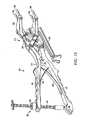
発明者らによって確認されているこれら既知の拡張可能な椎骨インプラント又は人工器官に伴う1つの問題は、2段階操作を必要とすることである。先ず、1つの器具を使って人工器官を椎間腔に挿入しなければならない。第2段階は、第2の器具を使ってインプラントを要求される高さに拡張する段階を含んでいる。2つの器具を使用することで、処置の煩雑性が増し、手術時間が延び、患者の危険性が増すことになり、また、そこには、器具が狭い手術開口部内で互いにぶつかり合うという危険性が存在する。 One problem with these known expandable vertebral implants or prostheses identified by the inventors is that they require a two-step operation. First, the prosthesis must be inserted into the intervertebral space using a single instrument. The second stage includes expanding the implant to the required height using the second instrument. The use of two instruments increases the complexity of the procedure, increases surgical time, increases patient risk, and there is a risk that the instruments will collide with each other within a narrow surgical opening. Exists.
スクリュー原理に基づくその様なインプラントに伴うもう1つの問題は、発明者らが認識している様に、インプラントを挿入した後で拡張するのに、一方の部分を回転させる必要があることが理由で、別の問題が発生する。その様な閉じ込められた空間では、この回転を実現するのは難しい。その様なインプラントに伴う別の問題は、例えば、臨床医は、装置を拡張している時の脊椎の抵抗力を直接感じることができないため、拡張時に隣接する椎体に加える力を制御するのが難しいことである。 Another problem with such implants based on the screw principle is that, as the inventors have recognized, it is necessary to rotate one part to expand after inserting the implant. Another problem occurs. In such a confined space, this rotation is difficult to achieve. Another problem with such implants is, for example, that the clinician cannot directly feel the resistance of the spine when expanding the device, so it controls the force applied to the adjacent vertebral body during expansion. Is difficult.
これらの人工器官に伴う別の問題は、発明者らが認識している様に、それらが円筒形状であるという理由で生じる問題であり、例えば、人工器官は、本来備わっている捩れに対する抵抗力が弱いため、互いに内側に捩れる恐れがある。インプラントは、隣接する椎体の間の所定位置に係止され、脊椎に捻り運動を加えた時、捩られても相対運動に抵抗することが重要である。 Another problem with these prostheses is that they arise because they are cylindrical, as the inventors have recognized, for example, prostheses are inherently resistant to twisting. May be twisted inward due to weakness. It is important that the implant is locked in place between adjacent vertebral bodies and resists relative motion when twisted when the spine is twisted.
金属で作られたインプラントのもう1つの問題は、弾性係数が、固定される相手の椎体より遙かに高いことである。このため剛性が比較的高くなり、その結果、隣接する椎体に応力が伝達され、応力遮蔽及び骨移植片分解吸収による応力骨折を引き起こす可能性がある。 Another problem with implants made of metal is that the modulus of elasticity is much higher than the counterpart vertebral body to be fixed. This results in a relatively high stiffness, which results in stress being transmitted to the adjacent vertebral bodies, which can cause stress fractures due to stress shielding and bone graft resorption.
発明者らが認識しているもう1つの問題は、インプラントは、一般には脊椎に十分に固定されず、単独で使用すると脊椎の安定化を十分に図ることができないことである。この必要な安定性を実現するため、インプラントには、脊椎とインプラントに取り付けられるプレート又はロッドベースのシステムの様な第2のシステムが必要になる。この追加のシステムは、一体化されておらず、追加の費用が発生し、患者にとっても手術時間と危険性が増す。 Another problem that the inventors have recognized is that implants are generally not well fixed to the spine and cannot be adequately stabilized when used alone. To achieve this necessary stability, the implant requires a second system, such as a plate or rod based system attached to the spine and the implant. This additional system is not integrated, incurs additional costs, and increases surgical time and risk for the patient.
もう1つの問題は、インプラントは、一般に構造的に受容可能な材料で作られてはいるが、体内に無期限に留置されることである。その様な、融合を目的として設計された金属製インプラントは、天然の骨より大きいヤング係数を有しているので、隣接するレベルに機械的応力遮蔽が生じて、隣接する椎体に高い応力、変形及び/又は骨折を引き起こす恐れがある。 Another problem is that implants are generally made of structurally acceptable materials, but remain in the body indefinitely. Such metal implants designed for fusion have a Young's modulus greater than that of natural bone, resulting in mechanical stress shielding at adjacent levels, high stress on adjacent vertebral bodies, May cause deformation and / or fracture.
本発明の幾つかの実施形態は、上で指摘した問題を軽減する、人工椎骨器官を含むインプラント又は人工器官を提供している。 Some embodiments of the present invention provide an implant or prosthesis comprising an artificial vertebral organ that alleviates the problems noted above.
本発明の第1の態様によれば、骨部分を備えているか又は骨部分と関係付けられている損傷した身体構造を修復するためのインプラントが提供されており、同インプラントは、生物分解吸収性材料で構成されており、内部での骨成長を促進する1つ又はそれ以上の内部開放有孔構造と、高密度周辺構造と、を備えている。 According to a first aspect of the present invention there is provided an implant for repairing a damaged body structure comprising or associated with a bone part, said implant being biodegradable and absorbable Consists of materials and includes one or more internally open perforated structures that promote bone growth therein and a high density peripheral structure.
開放有孔構造とは、骨材料が一体化できるように、例えば、孔の中へそして孔を通って成長できるように、空隙又は孔が全体的に相互に繋がっている(例えば、スポンジの様な)構造であると理解頂きたい。生物分解吸収性材料とは、体内に植え込まれてしまうと、時間の経過と共に体液の生化学作用によって吸収され、最終的に、インプラント全体が分解されるか又は天然の身体構成材質(例えば、骨又は組織)に交換され/置き換えられる材料であると理解頂きたい。高密度構造とは、空隙又は孔が、低密度構造より少ない構造を意味する。高密度構造は、低密度構造より強度が高くなる。従って、インプラントの周辺構造が要求される機械的強度を提供すると共に、一方で、内部有孔構造が材料の成長を増進するようになっていることが好都合である。 An open perforated structure is such that the voids or pores are generally interconnected (e.g., sponge-like) so that the bone material can be integrated, e.g., grown into and through the pores. I would like you to understand that it is a structure. A biodegradable absorbable material, once implanted in the body, is absorbed by the biochemical action of body fluids over time, and eventually the entire implant is degraded or natural body constituent materials (e.g., It should be understood that the material is replaced / replaced by (bone or tissue). A high density structure means a structure having fewer voids or pores than a low density structure. The high density structure is stronger than the low density structure. Thus, it is advantageous that the peripheral structure of the implant provides the required mechanical strength while the internal perforated structure is adapted to enhance material growth.
インプラントが生物吸収分解性材料で作られていることは、時間が経てば、骨は、インプラントの中へ成長していき、インプラントを近接する骨部分に完全に融合させるという意味を持っており、好都合である。 The fact that the implant is made of a bioresorbable material means that over time, the bone will grow into the implant and fully fuse it with the adjacent bone parts, Convenient.
或る特定の実施形態では、生物吸収分解性材料は、関係付けられている骨部分からの内向きの骨成長を助長する骨伝導性材料である。更に特定された或る実施形態では、材料は、骨を体内の化学反応により材料内で自然発生的に成長させる骨誘導性も有している。更に厳密に特定すれば、材料は、骨伝導性と骨誘導性の両方を有している。 In certain embodiments, the bioresorbable degradable material is an osteoconductive material that promotes inward bone growth from the associated bone portion. In some more specific embodiments, the material also has osteoinductivity that causes the bone to grow spontaneously in the material by internal chemical reactions. More precisely, the material is both osteoconductive and osteoinductive.
内部構造と周辺構造は、一体型であってもよい。インプラントは、単一構造構成要素を有していてもよい。内部構造と周辺構造は、互いに接続されていてもよい。代わりに、内部構造と周辺構造は、互いに別体であってもよい。 The internal structure and the peripheral structure may be integrated. The implant may have a single structural component. The internal structure and the peripheral structure may be connected to each other. Alternatively, the internal structure and the peripheral structure may be separate from each other.
インプラントは、2つ以上の内部有孔構造を備えていてもよい。各内部有孔構造は、異なる密度を有していてもよい。 The implant may comprise more than one internal perforated structure. Each internal perforated structure may have a different density.
或る特定の実施形態では、生物吸収分解性材料は、関係付けられている骨部分からの内向きの骨成長を助長する骨伝導性材料である。更に特定された或る実施形態では、材料は、骨誘導性も有している。 In certain embodiments, the bioresorbable degradable material is an osteoconductive material that promotes inward bone growth from the associated bone portion. In certain more specific embodiments, the material is also osteoinductive.
1つの実施形態では、インプラントは、損傷した円板を修復するための脊椎インプラントである。或る特定の実施形態では、インプラントは、椎間板切除術に続いて椎間空間に挿入されるように構成されている。 In one embodiment, the implant is a spinal implant for repairing a damaged disc. In certain embodiments, the implant is configured to be inserted into the intervertebral space following a discectomy.
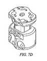
インプラントは、インプラントを隣接する椎体に固定するための1つ又はそれ以上の締結具用の1つ又はそれ以上の穴、1つ又はそれ以上の部分穴、溝、又はスロットを備えていてもよい。締結具の例として、スクリュー、ピン、ステープル、ダーツ、ボラード、又は他の適した固定具が挙げられる。締結具を係止して抜け落ちないようにするため、抜け出し防止手段を設けてもよい。抜け出し防止手段は、締結具又はインプラント/人工器官と一体の一次的手段であってもよい。代わりに、抜け出し防止手段は、インプラントに固定できる二次的装置を備えていてもよい。 The implant may comprise one or more holes, one or more partial holes, grooves, or slots for one or more fasteners for securing the implant to an adjacent vertebral body. Good. Examples of fasteners include screws, pins, staples, darts, bollards, or other suitable fasteners. In order to lock the fastener and prevent it from falling off, a pull-out prevention means may be provided. The escape prevention means may be a primary means integral with the fastener or the implant / prosthesis. Alternatively, the escape prevention means may comprise a secondary device that can be secured to the implant.
内向きの骨成長を助長するための更なる穴又は開口部を設けてもよい。1つの実施形態では、インプラントは、概ね方形又は矩形の断面を有している。インプラントは、中空の中央空間を取り囲んでいる壁を有している。代わりに、インプラントは、自家移植片、同種移植片、及び/又は合成骨材料の様な生体材料が充填される中央空間を有していてもよい。 Additional holes or openings may be provided to promote inward bone growth. In one embodiment, the implant has a generally square or rectangular cross section. The implant has a wall surrounding a hollow central space. Alternatively, the implant may have a central space filled with biomaterials such as autografts, allografts, and / or synthetic bone materials.
別の実施形態では、インプラントは、部分椎体、又は1つ又はそれ以上の全椎体に置換するための人工器官である。 In another embodiment, the implant is a prosthesis for replacing a partial vertebral body or one or more whole vertebral bodies.
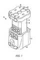
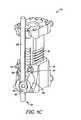
本発明の1つの実施形態によれば、下椎体の上面に係合するための下端面と長手方向部分とを有する第1下部材と;第2椎体の相対する下面に係合するための上端面と、長手方向に滑動することにより上部材が下部材に対して動けるように下部材の長手方向部分と協働するようになっている部分と、を有する第2上部材と;上部材を下部材に固定するための固定構造と;を備えたインプラントが提供されている。 According to one embodiment of the invention, a first lower member having a lower end surface and a longitudinal portion for engaging the upper surface of the lower vertebral body; for engaging the opposing lower surface of the second vertebral body A second upper member having a top end surface and a portion adapted to cooperate with a longitudinal portion of the lower member such that the upper member can move relative to the lower member by sliding longitudinally; An anchoring structure is provided for securing the member to the lower member.
或る特定の実施形態では、下部材の長手方向部分又は上部材の協働部分の何れかは、他方の部材の協働部分を、密な滑り嵌めが提供できるように受け入れる内径部を有する端の開いた部分である。 In certain embodiments, either the longitudinal portion of the lower member or the cooperating portion of the upper member has an inner diameter that receives the cooperating portion of the other member so that a close sliding fit can be provided. The open part of
特定の実施形態では、本発明は、特に、側方外科的進入法又は正中(前方)外科的進入法により移植できるように構成されている。 In certain embodiments, the present invention is specifically configured to be implantable by a lateral or midline (anterior) surgical approach.
下部材と上部材の間の固定構造は、上部材を最大と最小の高さ(又は長さ)の間の高さ位置で下部材に固定することにより、インプラントの高さ(又は長さ)を調節できるように構成してもよい。これには、単一寸法のインプラントが、脊椎寸法と位置が広範囲に異なる1つ又はそれ以上の全椎体又は部分椎体に置き換えて使用できるようになるという利点がある。 The fixation structure between the lower member and the upper member is the height (or length) of the implant by fixing the upper member to the lower member at a height position between the maximum and minimum height (or length). You may comprise so that adjustment is possible. This has the advantage that a single dimension implant can be used to replace one or more whole or partial vertebral bodies with widely varying spinal dimensions and positions.
上記インプラントの各部材は、通常、隣接する上椎体と下椎体に直接固定される。特定の実施形態では、インプラントは、前向きと後向きの何れの向きにも設置できるように反転可能である。インプラントは、前向きでは、上椎体と下椎体の間に中立又は脊柱前弯角を提供し、反転させて後方きにすると、中立又は脊柱後弯角を提供する。 Each member of the implant is usually fixed directly to the adjacent upper and lower vertebral bodies. In certain embodiments, the implant can be inverted so that it can be placed in either a forward or backward orientation. The implant, when viewed forward, provides a neutral or anterior spinal depression between the upper and lower vertebral bodies, and when inverted and posteriorly provides a neutral or posterior depression.
或る代わりの構成では、上部材と下部材は、インプラントが脊柱後弯角と脊柱前弯角の混成したものを提供できるように、それぞれの端面の形状と角度が対称になっていてもよい。例えば、インプラントは、上端面側では脊柱前弯角を提供し、下端面側では脊柱後弯角を提供するようにしてもよい。この結果、術中の煩雑さは軽減され、在庫目録の範囲(即ち、異なる患者/傷害に応じるために必要である異なる型式/寸法のインプラントの仕入れ)を減らすことができる。 In an alternative configuration, the upper member and the lower member may be symmetrical in shape and angle at their respective end faces so that the implant can provide a mixture of posterior and anterior lordosis angles. . For example, the implant may provide an anterior spinal depression on the upper side and a posterior depression on the lower side. As a result, intraoperative complexity is reduced and the inventory inventory range (ie, the purchase of different types / sizes of implants required to accommodate different patients / injuries) can be reduced.
或る代わりの構成では、上部材と下部材は、法線又は中立角を提供する。 In one alternative configuration, the upper member and the lower member provide a normal or neutral angle.
或る好適な実施形態では、第1及び第2部材は、放射線透過性材料で形成されており、代表的には、ポリエーテルエーテルケトン(PEEK)の様なポリマーである。X線撮影した時、−例えば、融合度をモニターしようとして撮影した場合、脊椎の部分が覆い隠されないのが好都合である。 In certain preferred embodiments, the first and second members are formed of a radiolucent material, typically a polymer such as polyetheretherketone (PEEK). When X-rays are taken--for example, when taking a picture to monitor the degree of fusion, it is advantageous that the spine part is not obscured.
実施形態によっては、ポリマー、ポリマー複合材、生物分解吸収性材料、又は他の生体材料で形成してもよい。材料は、ヤング係数が骨に近いという特徴を呈するのが望ましい。他の好適な材料特性として、放射線透過性、及び脊椎の安定化に適切な機械的強度が挙げられる。材料は、分解吸収性及び/又は骨誘導性及び/又は骨刺激性及び/又は骨伝導性を有する、合成の骨代用品、バイオガラス(例えば、燐酸塩ガラスなど)、又はセラミック材料であってもよい。 In some embodiments, it may be formed of a polymer, a polymer composite, a biodegradable absorbent material, or other biomaterial. Desirably, the material exhibits the characteristics that its Young's modulus is close to that of bone. Other suitable material properties include radiolucency and mechanical strength suitable for spinal stabilization. The material may be a synthetic bone substitute, bioglass (eg, phosphate glass, etc.), or ceramic material that has resorbable and / or osteoinductive and / or bone stimulating and / or osteoconductive properties. Also good.
下部材と上部材の断面は、互いに対する回転及び隣接する骨構造に対する回転に抵抗する形状を有しているのが望ましい。断面が捩りに対する高い抵抗を提供しているのが好都合である。 The cross section of the lower member and the upper member preferably has a shape that resists rotation with respect to each other and rotation with respect to the adjacent bone structure. Conveniently, the cross section provides a high resistance to torsion.
下部材と上部材の固定具は、クリップ、又はばね、又はねじの切られたボルト、又は(単数又は複数の)ピン、又は(単数又は複数の)ステープル、又は同様の形状と機能を有する他の締結具を備えていてもよい。インプラントは、固定手段を、下部材の長手方向部分の壁の単一又は複数の穴に挿入して、上部材の長手方向部分に形成されている単一又は複数の穴に係合させることができるように構成してもよい。穴に代わるものとして、下部材及び上部材の長手方向部分の協働面には、固定手段受け入れ用の部分穴、溝、又はチャネルが形成されていてもよい。 Lower member and upper member fasteners are clips, or springs, or threaded bolts, or pin (s), or staple (s), or others having similar shape and function The fastener may be provided. The implant may insert the securing means into the single or multiple holes in the wall of the longitudinal portion of the lower member and engage the single or multiple holes formed in the longitudinal portion of the upper member. You may comprise so that it can do. As an alternative to the holes, the cooperating surfaces of the longitudinal portions of the lower member and the upper member may be formed with partial holes, grooves or channels for receiving the fixing means.
1つの実施形態では、上部材の長手方向部分の断面は、一対の実質的に平行な平坦面を有しており、各面は、面を横方向に横断して伸張している複数の事前に形成された穴又は溝を含んでおり、事前に形成されている溝は、ねじの切られたバー又はピン又はステープルのアームを受け入れることができる大きさを有している。穴又は溝又はチャネルは、複合材、又はスリーブ、又は類似のもので補強してもよい。上部材及び/又は下部材には、穴又は溝又はチャネルの列を設けて、上部材の1つ又はそれ以上の穴/溝と下部材の1つ又はそれ以上の穴/溝とを整列させることにより画定される挿入位置の或る一定の範囲が提供されるようにしてもよい。孔のピッチ、即ちインプラントを堅く係止させる際の増分は、外科処置技法を支援できるように十分小さくなっている。孔又は溝又はチャネルと、ねじの切られたバー又はピン又はステープルは、どの様な適した断面のものであってもよく、例えば、円形のものであってもよい。下部材の長手方向部分の壁の単一又は複数の穴は、事前に形成されていてもよいし、挿入処置の一環として形成することもできる。 In one embodiment, the cross-section of the longitudinal portion of the upper member has a pair of substantially parallel flat surfaces, each surface being a plurality of pre-extending surfaces transversely across the surface. The pre-formed groove is sized to receive a threaded bar or pin or staple arm. The hole or groove or channel may be reinforced with a composite, or sleeve, or the like. The upper member and / or the lower member may be provided with a row of holes or grooves or channels to align one or more holes / grooves in the upper member with one or more holes / grooves in the lower member. A certain range of insertion positions defined thereby may be provided. The pitch of the holes, i.e. the increment in tightly locking the implant, is small enough to support the surgical technique. The holes or grooves or channels and the threaded bars or pins or staples may be of any suitable cross-section, for example circular. The single or multiple holes in the wall of the lower member longitudinal portion may be pre-formed or formed as part of the insertion procedure.
インプラントの高さは、一方の部材にピン又はステープルを挿通する前に、望ましくは平行運動によって調節することができ、要求された高さに配置できたら、ねじが切られたものでも切られていないものでもよいが、ピン又はステープルを他方の部材の穴又は溝に挿入して係合させることができるようになっているものが好都合である。一例的な実施形態では、穴又は溝又はチャネルは、最大3.5mmまでの間隔を空けて配置されている。或る好適な実施形態では、間隔は、約1.5mmから3.5mmまでの間、望ましくは約2.5mmであり、高さを、約1.5mmから3.5mmまでの間の調節幅で調節することができるようになっている。調節幅をより小さく又はより大きくするには、より小さいか又はより大きい穴又は溝又はチャネルを使用するか、又は第1部材側に複数の事前に形成された穴を設けて、(単数又は複数の)ピン又は(単数又は複数の)ステープルを挿通させる位置を選定できるようにすることで対応できることが理解頂けるであろう。 The height of the implant can be adjusted, preferably by parallel motion, before inserting a pin or staple through one member, and once it has been placed at the required height, it can be threaded. Although not required, it is advantageous that a pin or staple can be inserted and engaged in a hole or groove in the other member. In one exemplary embodiment, the holes or grooves or channels are spaced apart up to 3.5 mm. In a preferred embodiment, the spacing is between about 1.5 mm and 3.5 mm, desirably about 2.5 mm, and the height is adjusted between about 1.5 mm and 3.5 mm. It can be adjusted with. To make the adjustment width smaller or larger, use smaller or larger holes or grooves or channels, or provide a plurality of pre-formed holes on the first member side (one or more). It will be appreciated that this can be accommodated by allowing selection of the position through which the pin or staple (s) are to be inserted.
また別の実施形態では、下部材と上部材は、両部材の事前に形成されている穴にスクリュー、ダーツ、又はボラード、或いは、同様の機能を有する固定具を通して、対応する椎体に固定される。これは、脊椎に加えられる力に抵抗する上で脊椎の安定化を迅速に図ることができるという利点をもたらす。 In another embodiment, the lower member and the upper member are fixed to the corresponding vertebral bodies through screws, darts, bollards, or similar functioning fasteners in the pre-formed holes of both members. The This provides the advantage that the spine can be stabilized quickly while resisting forces applied to the spine.
また別の実施形態では、インプラントを、前方又は側方プレート又はロッドシステムに錨着固定するための錨着固定手段が設けられている。プレート又はロッドシステムは、インプラントと一体化されているのが望ましい。錨着固定手段は、第1及び/又は第2部材に、多軸連結アッセンブリの端部を受け入れるための開口部を備えていてもよい。多軸連結アッセンブリは、連結部を前方プレート、ロッド、又は他の補助固定システムの一部を形成している長手方向ロッド又はバーに固定するためのクランプ固定装備を含んでいてもよい。多軸連結を使用すると、精密に整列させる必要無しに、インプラントをプレート又はロッドシステムに錨着固定できるのが好都合である。本発明は、臨床医がそうしたいと思えば、脊椎の安定化を増強する手段として後方固定を利用できるようにもしている。或る代わりの錨着固定手段は、両部材とプレートの間に、ヒンジ式継手を備えていてもよい。 In yet another embodiment, anchoring means are provided for anchoring the implant to the anterior or lateral plate or rod system. The plate or rod system is preferably integrated with the implant. The fastening means may comprise an opening in the first and / or second member for receiving the end of the multiaxial coupling assembly. The multiaxial coupling assembly may include a clamping fixture for securing the coupling to a longitudinal rod or bar that forms part of a forward plate, rod, or other auxiliary fastening system. Using a multiaxial connection advantageously allows the implant to be clamped to the plate or rod system without the need for precise alignment. The present invention also allows posterior fixation to be used as a means to enhance spinal stabilization if the clinician wishes to do so. Some alternative fastening means may comprise a hinged joint between both members and the plate.
もう1つの実施形態では、インプラントの固定前に第1及び第2部材を動かしてインプラントの高さを増減できるように、拡張用具を両部材に係合させる手段が設けられている。拡張用具は、用具の1つ又はそれ以上のアッタチメントを第1及び/又は第2部材に設けられた開口部の中へ挿入することにより、各部材に係合させてもよい。拡張用具は、下の本発明の第4の態様による器具であってもよい。 In another embodiment, means are provided for engaging the expansion tool with both members so that the height of the implant can be increased or decreased by moving the first and second members prior to fixation of the implant. The expansion device may be engaged with each member by inserting one or more attachments of the device into openings provided in the first and / or second members. The expansion device may be a device according to the fourth aspect of the invention below.
本発明のまた別の態様によれば、椎骨インプラントを挿入し且つ拡張するための器具が提供されており、同器具は、前記椎骨インプラントの上及び下部材それぞれに係合するための上及び下係合アームと;前記器具を作動させるために医師が操作できるようにするための前記係合アームより遠位側の入力手段と;前記アームの互いに離れていく動きに反応して、前記アームを互いに平行に整列した状態に維持しながら、前記インプラントを拡張する手段と、を備えている。 In accordance with yet another aspect of the present invention, an instrument for inserting and expanding a vertebral implant is provided, the instrument being upper and lower for engaging the upper and lower members of the vertebral implant, respectively. An engagement arm; input means distal to the engagement arm to allow a physician to operate to actuate the instrument; and in response to the movement of the arm away from each other, the arm Means for expanding the implant while maintaining parallel alignment with each other.
各アームは、前記インプラントの前記上及び下部材それぞれの対応する場所に係合するための1つ又はそれ以上のアッタチメントを備えているのが望ましい。アッタチメントは、両部材の対応する穴の中へ挿入するための1つ又はそれ以上のフィンガを備えていてもよい。特定の実施形態では、フィンガは円形断面を有している。しかしながら、他の適した断面形状として、楕円形又は矩形の断面が含まれ、又はそれらの組み合わせを備えていてもよい。 Each arm preferably includes one or more attachments for engaging corresponding locations on each of the upper and lower members of the implant. The attachment may include one or more fingers for insertion into corresponding holes in both members. In certain embodiments, the fingers have a circular cross section. However, other suitable cross-sectional shapes may include elliptical or rectangular cross-sections, or may comprise a combination thereof.
もう1つの実施形態では、アッタチメントは、アームを部材にクランプ固定するためのクランプ固定手段を備えている。 In another embodiment, the attachment comprises clamping means for clamping the arm to the member.
入力手段は、一対のハンドル部材であって、医師が手の中で両部材をきつく握って互いに近づけることによって器具を作動させるようになっているハンドル部材を備えていてもよい。ハンドル部材を握り合わせる動作に対する抵抗を与えるための付勢手段を設けて、器具の拡張に相関付けるようにしてもよい。 The input means may comprise a pair of handle members that are adapted to actuate the instrument by the physician grasping both members in their hands and bringing them closer together. Biasing means may be provided to provide resistance to movement of the handle member to correlate with instrument expansion.
実施形態は、更に、器具を拡張された位置に係止するための係止手段を備えていてもよい。拡張された位置は、器具を一杯まで縮めた位置から動かしたどの様な位置でもよい。 Embodiments may further comprise locking means for locking the device in the expanded position. The expanded position may be any position where the instrument is moved from a fully retracted position.
実施形態によっては、更に、椎骨インプラントを拡張された状態で固定するための締結具を支持するための整列支持部材を備えていてもよい。整列支持部材は、更に、固定用具(例えば、ねじ回し又は類似のもの)を位置付けるためのガイド手段を含んでいてもよい。 Some embodiments may further include an alignment support member for supporting a fastener for securing the vertebral implant in an expanded state. The alignment support member may further include guide means for positioning a securing tool (eg, a screwdriver or the like).
使用時、外科医は、1つの器具(例えば、伸延用具)を使って1回の操作で、インプラントを脊椎に挿入し、更にインプラントを要求されている高さまで拡張することができるのが好都合である。更に、外科医は、インプラントの拡張に抵抗する力を感じるか又はその感覚を得ることができ、これを適切な拡張量を測るのに利用することができるのが好都合である。例えば、インプラントの上及び下部材が取り付けられた拡張用具を、折り畳んだ姿勢で脊椎に挿入してもよい。それぞれの部材が椎体内の正しい解剖学的位置に着座すると、伸延用具を作動させて、アッタチメントを、要求されている解剖学的高さが実現されるまで、平行運動によって引き離してゆく。この時点で、器具は、インプラントに係止してインプラントを拡張された位置に保持することができ、締結具を挿入し、整列締結具支持部材を使用して、インプラントを定着させることができる。器具は、力指標を表示することによって拡張に対抗する荷重の値をフィードバックしてもよい。インプラントが所定位置に固定されてしまえば、器具をインプラントから引き抜いてフィンガをインプラントの上及び下部材の穴から滑り出させるだけで、又は別のやり方で器具をインプラントから切り離しさえすれば、器具を取り外すことができる。 In use, the surgeon can conveniently insert the implant into the spine with a single operation (eg, distraction tool) and further expand the implant to the required height. . In addition, the surgeon can advantageously feel or obtain a force that resists the expansion of the implant, which can be used to measure the appropriate amount of expansion. For example, an expansion tool with upper and lower implant members attached may be inserted into the spine in a folded position. As each member sits in the correct anatomical position within the vertebral body, the distraction tool is actuated to pull the attachment apart by a parallel motion until the required anatomical height is achieved. At this point, the instrument can be locked to the implant to hold the implant in the expanded position, a fastener can be inserted, and the alignment fastener support member can be used to anchor the implant. The instrument may feed back the value of the load against expansion by displaying a force indicator. Once the implant is locked in place, simply pull the instrument out of the implant and slide the fingers out of the holes in the top and bottom members of the implant, or otherwise detach the instrument from the implant. Can be removed.
伸延用具は、挿入と伸延の両用器具として使用できるのが好都合である。更に、伸延用具の使用は、操作が簡単で、医師に、両部材の組み立て、伸延の場合の力又は機械的な利点、各部材の穴又は溝の相対位置、及び使用する部材の寸法測定に関する触覚的フィードバックを提供することも好都合である。伸延用具の特徴は、整列支持部材を用いて、上部材と下部材が(単数又は複数の)固定締結具を受け入れることができるように正しく整列したら分かるようにしたことである。 Advantageously, the distraction tool can be used as both an insertion and distraction instrument. In addition, the use of the distraction tool is easy to operate and relates to the physician assembling both members, the force or mechanical advantage of distraction, the relative position of the holes or grooves in each member, and the dimensional measurement of the member used It is also advantageous to provide tactile feedback. A feature of the distraction tool is that an alignment support member is used so that the upper member and the lower member can be seen when properly aligned to receive the fixed fastener (s).
各部材が要求されている解剖学的位置まで伸延されると、伸延用具は、固定用具、例えば、ねじ回しを、締結具、例えば、ピン、スクリュー、又はステープルの駆動部の中へ案内するという更なる利点を発揮する。 As each member is distracted to the required anatomical position, the distraction tool will guide the fixation tool, eg, a screwdriver, into the fastener, eg, pin, screw, or staple drive. Demonstrate further advantages.
本発明の実施形態のまた別の態様によれば、カーテンをインプラント上の複数の位置に固定して、上椎体と下椎体の間に、骨移植片を入れることができる、取り囲まれた空間が形成されるように構成した椎骨インプラントが提供されている。骨移植片は、同種移植片、自家移植片、又は合成であってもよい。移植片は、粒状の形態であってもよいし、又は例えば、リブストラットの様に半付形又は完全付形済みであってもよい。 According to yet another aspect of an embodiment of the present invention, a curtain can be secured at multiple locations on the implant to enclose a bone graft between the upper and lower vertebral bodies. A vertebral implant configured to form a space is provided. The bone graft may be allograft, autograft, or synthetic. The implant may be in granular form or may be half-shaped or fully shaped, for example, like rib struts.
カーテンを固定するための手段は、インプラント側に設けられている突起に嵌め込むための小穴をカーテン側に備えていてもよい。突起は、人工器官を拡張する伸延器が使用するのと同じ開口に差し込まれる。代わりに、カーテンは、開放編組型、ウェブ様、又は網状の構造を有していてもよく、カーテン開放構造を局所的に変形させ、錨着固定点又は突起に被せて装着することによってインプラントに固定されるようにしてもよい。 The means for fixing the curtain may be provided with a small hole on the curtain side for fitting into a protrusion provided on the implant side. The protrusion is inserted into the same opening used by the distractor that expands the prosthesis. Alternatively, the curtain may have an open braided, web-like, or net-like structure that is locally deformed in the curtain open structure and attached to the implant by mounting it over a fixation point or protrusion. It may be fixed.
移植片保持カーテンは、生物適合性材料で形成され、血管新生及び骨成長を許容する構造を有しているのが望ましい。これの利点は、移植片保持カーテンが、骨移植片を、外傷又は腫瘍が理由で側方式に植え込まれる場合は前面の、又は2レベル修正のために前方式に植え込まれる場合にはその両側面の、所定位置に保持するということである。従って、融合は、最も高い脊椎荷重を担持し最も脈管が多い個所であり、融合を起こすのに望ましい環境が整っている、椎体の前面で促進される。移植片保持具に適した材料としては、ポリエステル、コラーゲン(基質/固体シート)、PEEKファイバー、又は低部分極性材料が挙げられる。保持カーテンは、開放編組構造を有し、細かい骨移植片又は骨代用品も粗い骨移植片又は骨代用品も保持できる程度に小さいが、但し、血液供給並びに栄養分が流入するのを許容する程度には大きいことが望ましい。 The graft holding curtain is preferably formed of a biocompatible material and has a structure that allows angiogenesis and bone growth. The advantage of this is that the graft-holding curtain can be used when the bone-graft is implanted in the front mode if it is implanted due to trauma or tumor, or in the previous mode for bilevel correction. That is, it is held at a predetermined position on both sides. Thus, fusion is facilitated at the front of the vertebral body, where it bears the highest spinal load, is the most vascular, and has the desired environment for fusion to occur. Suitable materials for the graft holder include polyester, collagen (matrix / solid sheet), PEEK fiber, or low partial polarity material. The holding curtain has an open braided structure and is small enough to hold a fine bone graft or bone substitute or a coarse bone graft or bone substitute, but only to allow blood supply and nutrients to enter. It is desirable to be large.
移植片保持カーテンは、インプラントへの取り付けをやり易くし、カーテンに張りを与え又は伸展を許容するエラストマー区間を含んでいてもよい。或る特定の態様では、骨移植片保持カーテンは、放射線透過性を有している
更に特定された或る実施形態では、移植片保持カーテンは、インプラントの両部材にしっかりと取り付けられ、その後、装置の拡張に伴って伸展/伸張するように構成されている。The graft holding curtain may include an elastomeric section that facilitates attachment to the implant and allows the curtain to be tensioned or allowed to extend. In certain aspects, the bone graft retention curtain is radiolucent. In certain more specific embodiments, the graft retention curtain is securely attached to both members of the implant, and thereafter It is configured to stretch / extend as the device expands.
骨移植片材料が充填された封包体を形成することにより、材料の脱落が防止されるのが好都合である。骨移植片材料は、骨成長を促し、やがて椎体と融合することで脊椎の強度を高めることができる。 Advantageously, the formation of an envelope filled with bone graft material prevents the material from falling off. Bone graft materials can promote bone growth and eventually fuse with the vertebral body to increase the strength of the spine.
骨移植片材料は、追加的に、インプラントの中央部分内に挿入してもよい。 Bone graft material may additionally be inserted into the central portion of the implant.
この設計の別の特徴は、臨床的必要性によって、例えば、感染による炎症を伴う場合に、インプラントを外植できるようになっていることである。 Another feature of this design is that the clinical need allows explants to be explanted, for example when accompanied by inflammation from infection.
本発明の上記の特徴は、添付図面に関連して以下の詳細な説明を参照頂ければ、より理解し易くなるであろう。 The foregoing features of the present invention will become more readily understood by reference to the following detailed description, taken in conjunction with the accompanying drawings, in which:
図1から図3を参照すると、人工椎間器官70は、第1部材72と第2部材74を有している。第1部材72は、内径部76を有する管状構造である。第2部材74は、第1部材の内径部76との密な滑り嵌めを形成する断面を有する長手方向部分78を有している。第2部材74は、第1部材72に対し長手方向(図では上下方向)に滑動することができる。1つの実施形態では、第1及び第2部材はPEEKで形成することができる。 With reference to FIGS. 1 to 3, the artificial
第1部材72は、以下、下部材と称し、第2部材74は上部材と称することにするが、人工器官70は、上下逆にしても、等しく良好に機能するものと理解頂きたい。下部材72は、第1椎体(図示せず)の相対する上面に係合するための端面82を有している。上部材74は、第2椎体(図示せず)の相対する下面に係合するための端面84を有している。端面82、84のそれぞれには、椎体の骨を掴むための隆起した歯83、85、86が設けられており、それらは細長い歯又はリッジであってもよい。代わりに、端面82、84には、把持作用を提供する溝又はピラミッドの様な隆起した突起が設けられていてもよい。 The
内径部76と上部材74の長手方向部分78の断面は、上下部材間の相対回転に抵抗するために非円形状をしている。図示の実施形態では、内径部76側には一対の相対する面が設けられ、長手方向部分78のフランク側には対応する面89a、89bが設けられている。 The cross section of the
上部材74の面89a、89bの一方又は両方には、マトリクス状の水平方向穴88が設けられている。穴は、長手方向に、例えば2.5mmの間隔で配置されている。代わりに、面89a、89bそれぞれに、例えば2.5mmの間隔で配置されている一連の水平方向溝(図6に図示)90を設けてもよい。穴88又は溝90の間隔については、所望の増分で調節できるようにするのに適した又は望ましい度の様な間隔であってもよいと理解頂きたい。或る好適な間隔は、1.0から4.0mmの範囲にある。 One or both of the surfaces 89 a and 89 b of the
図2を参照すると、下部材72には、横方向に同部材の一方の側を通って内径部76の中へと伸張している一対の穴91aが設けられている。下部材72の相対する側には、対応する整列した一対の穴91bが設けられている。上部材74は、マトリクス状の穴88の何れか1つが、対応する穴91a、91bと整列するように位置決めすることができる。ピン又はステープル95を用意し、穴91aの内の1つに挿入し、ピン又はステープル95のアームを、下部材の壁を通して穴88の内の整列している1つの穴の中へ伸張させる。ピン又はステープル95は、これにより、穴の中で下及び上部材72、74の両部材に係合し、それらの相対位置を固定する。上及び/又は下部材72、74に穴又は溝を設けることは、インプラントを要求された高さに固定するのに好都合であることが理解頂けるであろう。しかしながら、これは、他の手段によって実現することができ、例えば、下部材又は上部材の一方又は他方と係合する別体の挿入部を用意して、同挿入部に固定手段を設けるようにしてもよい。 Referring to FIG. 2, the
マトリクス状の穴88の別の特徴は、それが、骨の内成長を許容する粗い有孔構造を作り出していることである。 Another feature of the matrix-like holes 88 is that it creates a rough perforated structure that allows bone ingrowth.
クランプ固定及び係止機構92は、ピン又はステープル95を所定の位置に固定し、それが、その後、後退して脱落するようなことの無いようにするために提供されている。このクランプ固定及び係止機構は、下部材72の溝に係合するピン又はステープルの頭部のフランジであってもよい。代わりに、クランプ固定機構は、ピンの軸部のねじ部又はローレットの形態を取ってもよい。 A clamp locking and
下部材72には、外壁に、横方向に本体の中のその端面82近くまで伸張している開口部93が設けられている。これらの開口部は、下部材72を完全に貫通して伸張していてもよいし、又は、代わりに、伸張して止まり穴になっていてもよい。同様の開口部94は、上部材74の端面84近くに設けられている。これらの開口部94は、伸延器具(図示せず)のフィンガを受け入れるのに用いられるが、それについては、下で詳しく説明する。 The
人工器官を椎間空間に設置するために、上部材の長手方向部分78を下部材72の内径部76内に着座させた状態で、人工器官70が縮められた位置にある間に、伸延器具のフィンガを開口部93、94に挿入する。この収縮状態の時、人工器官70はかなり短くなっており、空いている椎骨空間の中へ容易に挿入することができる。次いで、伸延用具を用いて、人工器官70を入れ子式に拡張する。下部材72の端面82は、第1(例えば、下側の)椎体の相対する面に係合する。人工器官70を拡張してゆくと、上部材74の端面84が第2(例えば上側の)椎体の相対する面と接触する。更に人工器官70を拡張すると、第1椎体と第2椎体が押し広げられ、脊椎は正常な及び/又は安定した状態と平衡を取り戻す。こうなると、椎体を押し広げるのに必要な力が大きくなるので、外科医は、伸延用具側の抵抗量を感じることができ、この感覚を利用して適切な拡張量が起こった時点を判断することができる。更に、力を大きくしてゆくと、端面82、84の歯、溝、又はピラミッド85、86が、椎体の骨を掴み、椎体と人工器官70の間に安定した界面が形成される。 In order to place the prosthesis in the intervertebral space, the distraction instrument is in a position where the
人工器官70が要求された高さに拡張されたら、ピン又はステーブル95を下部材72に挿入して、インプラントに標示されるか又は機械加工されている表示用造形を使用し、下部材72を上部材74と関係付けて固定する。上部材の穴88の内の1つ1つが下部材の穴91aと整列するように、微調整が必要な場合もある。ピン又はステープル95は、一旦挿入されると、クランプ固定装備92によって、抜け落ちないように固定される。 Once the
両側部から下部材72を貫いて、1つ又はそれ以上の傾斜穴96が伸張し、端面82に出てきている。これらは、締結具(例えば、スクリュー)がインプラントを下椎体に固定するのに使用される。上部材74には、同部材を上椎体に固定するために、同様の傾斜穴97が設けられている。1つ又はそれ以上の締結装置は、下部材を隣接する椎体に固定し、1つ又はそれ以上の締結装置は、上部材を隣接する椎体に固定する。 One or more inclined holes 96 extend from both sides through the
図2に示している様に、長手方向穴98は、上部材74を貫いて伸張している。これは、骨材料の内成長を考慮したものである。骨材料は、人工器官の挿入前に、穴98に入れて、内径部76下側部分の中まで挿入するのが望ましい。 As shown in FIG. 2, the
図4は、上椎体100と下椎体102の間に配置された人工器官70を示している。見て分かる様に、人工器官の前−後(A−P)方向寸法は、椎体のA−P方向寸法に比べて小さく、インプラントが取り付け相手の椎体の領域内に確実に収まるようになっている。人工器官のフットプリントは、前面と後面が凹んでいてもよい。この凹形により、装置の相対的に小さいA−P方向寸法が更に小さくなり、臨床医は、移植片材料を、人工器官の前側又は後側の何れの側に沿ってでも設置できるようになる。 FIG. 4 shows a
図1から図6は、側方又は斜方外科的進入法により植え込まれるインプラントを示している。インプラントは、等価的な機構を有しているが、但し、前方正中外科的進入法を考慮したやり方で構成されたものを提供してもよい。図7は、特に前方正中外科的進入法に適合させた実施形態に関連しており、これについては下で詳しく論じる。 1 to 6 show an implant that is implanted by a lateral or oblique surgical approach. The implant has an equivalent mechanism, but may be provided in a manner that allows for an anterior midline surgical approach. FIG. 7 relates to an embodiment specifically adapted to the anterior midline surgical approach, which will be discussed in detail below.
図5を参照すると、人工椎骨器官100は、図1から図4の人工椎骨器官70に似ているが、人工器官100の各側部には下端面106近くに、突起101、102が設けられている。各側部には、上端面105近くに別の突起103、104が設けられている。編組材料のカーテン107には、カーテンを、人工器官100の一方の側の突起101、103に固定できるようにする小穴108、109がある。カーテンには、別の小穴110、110aも設けられている。カーテンの材料は、体内で拒絶又は感染が起こる可能性が低くなるように、体組織と適合性を有するものを選択する(例えば、ポリエステル、PEEKファイバー)。 Referring to FIG. 5, the artificial
人工器官の脊椎への挿入に続き、骨移植片、例えば、自家移植片又は同種移植片又は合成骨を、人工器官100の前面に設置するのが望ましい。骨移植片は、粒状の形態又は付形されたロッド、例えば患者の肋骨から取ったものであってもよく、人工器官100に沿って配置する。これらの骨の切片は、やがて上方及び下方の椎体と融合し、脊椎の強度を更に高める。 Following insertion of the prosthesis into the spine, it is desirable to place a bone graft, such as an autograft or allograft or synthetic bone, in front of the
図5で分かる様に、カーテン107は、別の小穴110、110aを人工器官100の他方側の突起102、104に固定することによって、椎間空間に、人工器官100を取り囲む封包体111を形成するのに使用することができる。封包体111には、ここで、骨移植片材料を充填することができ、人工器官100と封包体111を形成しているカーテン107とが、骨移植片が脱落するのを防止する。このように、骨移植片は、骨の成長を促し、やがて椎体と融合するので、脊椎の強度が増す。 As can be seen in FIG. 5, the
従来、人工器官が(図1から図6の人工器官100に関して先に説明したやり方で)拡張可能である場合、カーテン107は、人工器官を拡張した時にカーテンが長手方向に伸びるように、人工器官が縮められた状態にあるときに、突起に固定することができた。これは、封包体111が椎間空間内で確実にその形状を維持できるようにするのに役立つ。 Conventionally, if the prosthesis is expandable (in the manner described above with respect to the
カーテン107のそれ以上に好都合な点は、必要性が出てくれば−例えば、人工器官を調節すること、又は後日、もっと多くの移植片材料を挿入することが要求された場合、このカーテンなら医師が容易に剥がして元に戻すことができることである。カーテンは、その場合、その様な処置の後で再度取り付けることができる。 A further advantage of
1つの実施形態では、カーテン107は、標準的な大きさに作られており、術中に大きさを合わす、例えば、高周波加熱を使って切断するようになっている。代わりに、カーテンは、1種類の大きさにして、伸展性能を持たせるようにしてもよい。もう1つの代替形態では、カーテンは、インプラントへの取り付けをやり易くし、カーテンに張りを与え又は伸展を許容するように、弾性区間を含んでいてもよい。 In one embodiment, the
図6aから図6cを参照すると、図1−3に示している型式とよく似た人工器官118は、人工器官118の上部材の平坦な側部に、横方向に横断して形成されている一連の平行な半円筒形の溝90を有しており、一方、下部材の内径部の相対する内面には、単一溝(見えない)が形成されている。単一溝は、下部材の壁を貫いて穴の中まで伸張している。上部材を下部材に対して昇降させると、単一溝は、一連の平行溝90の1つと整列し、円筒形開口部が形成されるので、そこに、ピン又はステープルを挿入することができる。図6に示している様に、ピン119が挿入されている。 Referring to FIGS. 6a-6c, a
人工器官118は、錨着固定装備122によって前方ロッドシステム120に連結させてもよい。錨着固定装備122は、プラグ部材124を含む多軸スクリュー連結部であり、プラグ部材は、人工器官118の下部材121の外面の開口部126に受け入れられる。プラグ部材124は、例えば、スクリューねじを用いて、下部材121の中へねじ込んで固定される。プラグ部材124は、雌ねじ部(図示せず)を利用してクランプ固定部材128に連結されているので、クランプ固定部材128に対するプラグ部材124の向きは或る範囲に亘って可変である。当該範囲内であればどの向きにも、スクリューを締め付けて連結部を固定することができる。クランプ固定部材128は、前方ロッドシステム120の一部を形成している長手方向ロッド125に連結され、ナット129を用いて、ナットをクランプ固定部材128のねじの切られた部分に係合させることにより、長手方向ロッド125に固定される。多軸連結部の向きが可変であることにより、人工器官は、厳密に整列させる必要無しに、ロッドシステムに錨着固定することができる。 The
分かり易くするために、図6cでは、長手方向ロッド125は1つしか示していないが、より一般的には、前方ロッドシステム120は、一対の平行ロッドを使用し、それぞれを、錨着固定装備を用いて人工器官に連結してもよい。 For clarity, only one
前方ロッドシステム120は、スクリューを利用して、人工器官118の上方と下方の椎体に固定される。このように、2つの椎体とそれらの間の人工器官から成る全アッセンブリは単一の剛性アッセンブリを形成して、人工器官と両椎体の間にどの様な運動も確実に起こらないようにしている。 The
上記手順を逆にして、人工器官118の修正を行ってもよい。 The
次に図7を見ると、特に前方正中外科的進入法による植え込みに適合させた或る実施形態が示されている。図7bに示している様に、穴と開口部は、この実施形態では前側に設けられ、前方進入法によってアクセスした時に、インプラントの操作、拡張、及び固定がやり易くなるようにしている。見て分かる様に、上面は、この実施形態が実際の正中線から離れる方向に僅かに傾くように、僅かにずらされており(f)、一般的に正中線位置に存在する生体脈管構造を回避するのに役立っている。この僅かなずれは必要条件ではなく、代替実施形態では、上面を前側と整列させることさえあり得る。 Turning now to FIG. 7, an embodiment is shown that is particularly adapted for implantation by an anterior midline surgical approach. As shown in FIG. 7b, the holes and openings are provided in the front side in this embodiment to facilitate manipulation, expansion, and fixation of the implant when accessed by an anterior approach. As can be seen, the upper surface is slightly offset so that this embodiment is slightly tilted away from the actual midline (f), and the biological vasculature generally located at the midline position. Helped to avoid. This slight shift is not a requirement, and in alternative embodiments, the top surface may even be aligned with the front side.
図8は、或る角度を付けた上面を提供できるよう構成されている上部材の断面を示している。図示の様に、面PPの平面は、脊椎の軸平面QQに平行ではなく、向きによって、脊柱前弯角又は脊柱後弯角を形成し易くなるように角度が付けられている。図9は、上部材の端が先細になって角RRを形成し、やはり軸平面QQに対して角度を成している代替型式を示している。図8又は図9の何れかに示されている角度形成は、下部材側の面でも、上端の角度に一致させるためにひっくり返すことを除き、等しく実施することができる。更に、図8又は図9の角度形成は、ここに説明している実施形態の何れもに実施することができる。一般に、図1から図3に示されている様な側方型インプラントであろと図7の様な前方型であろうと、角度は、脊椎の天然の曲率に合わせるのに適切である限り、前方から後方へ向けてでも、後方から前方に向けてでも、何れに向けて付けてもよい。 FIG. 8 shows a cross-section of the top member that is configured to provide an angled top surface. As shown, the plane of the plane PP is not parallel to the spinal axis plane QQ, but is angled to facilitate the formation of the anterior or posterior spinal depression depending on the orientation. FIG. 9 shows an alternative type in which the end of the upper member tapers to form an angle RR and is also angled with respect to the axial plane QQ. The angle formation shown in either FIG. 8 or FIG. 9 can be equally performed on the lower member side surface, except that it is turned over to match the angle of the upper end. Furthermore, the angle formation of FIG. 8 or FIG. 9 can be implemented in any of the embodiments described herein. In general, whether the lateral implant as shown in FIGS. 1 to 3 or the anterior type as in FIG. 7, the angle is sufficient as long as it is appropriate to match the natural curvature of the spine. It may be attached either from the rear to the rear or from the rear to the front.
図10は、伸延器具200を示している。器具200は、上係合アーム202と下係合アーム204を含んでいる。各アーム202、204は、図7から図9に示している人工器官70の下部材72及び上部材74の様な、上及び下部材それぞれの対応する穴の中へ挿入するためのフィンガ206、208を有している。 FIG. 10 shows a
伸延器具は、更に、上ハンドル210と下ハンドル212を含んでおり、それらは、係合アーム202、204から遠位方向に伸張している。上ハンドル210を下ハンドル212に向けて動かすと、係合アームが平行直線運動によって動くようになる機構214が設けられている。機構214は、上及び下ハンドル210、212が連結されている地点であるピボット216と、係合アーム202、204を、ピボット216から係合アームに向けて伸張している各ハンドル210、212部分に連接する軸回転式横部材218と、を含んでいる。 The distraction instrument further includes an
両ハンドル210、212の間には、板ばね220、222が配置されている。係止機構224は、ねじの切られたバー226を含んでおり、ねじの切られたバーは、下ハンドル212に軸回転式に取り付けられており、上ハンドル210の穴とナット228に通って伸張している。器具には機構214に沿って支持部材230が取り付けられており、係合アーム202、204のフィンガ206、208と整列している。 Leaf springs 220 and 222 are disposed between the
使用時、医師は、フィンガ206、208を、拡張可能なインプラントの上下部材の各係合穴の中へ(例えば、図7から図9の人工器官70の穴93、94の中へ)挿入する。インプラントは、一杯まで縮められた形態で、一対の椎体の間の空間に挿入するのが望ましい。医師は、次に、上下ハンドル210、212を強く握り合わせ、機構214が係合アーム202、204を引き離すようにする。これにより、インプラントが拡張され、両椎体の間の空間が伸延される。医師は、ハンドルを握り合わせるのに必要な力で、伸延に対する抵抗を感じることができる。板ばね220、222はこの力に対してほんの少ししか付け加えず、それらの重要な機能は、医師が握力を解いた時に、ハンドルが再度広がってインプラントが縮んでしまうようなことの無いようにすることである。 In use, the physician inserts
インプラントの選択は、係止機構224と一体型の定寸ゲージ(図示せず)を使用することにより実現することができる。 The selection of the implant can be achieved by using a
図11は、係合アーム202、204による、上椎体252と下椎体254の間のインプラント250の拡張を示している。調節可能な制限装置は、下アーム202に取り付けられている軸回転式リンク部材258と、上アーム204に取り付けられているチェーン式リンク260と、を含んでおり、器具が誤って使用され両椎体232と234の間の空間が過剰に伸延されるようなことの無いようにしている。 FIG. 11 shows the expansion of the
医師は、ハンドルを強く握り合わせるのに必要な力を感じることにより、適正又は所望の伸延量を判断することができる。この感覚フィードバックは、器具の実施形態の好都合な機構の1つに関係付けられる。そこで、ナット228を回して下げてゆき、上ハンドル210の上面に接触させることにより、器具をその位置に係止することができる。医師は、ここで、図12に示している様に、締結具を挿入することによってインプラントを固定することができるようになる。締め付け用具250は、締結具(ねじ、ピン、ステープル、ボラードなど)を掴む把持装置252を含んでいる。締め付け用具250は、支持部材230に支持されており、支持部材は、締結具がインプラントの締結具穴に直接挿入されるように、挿入用具を案内する働きもする。図13は、使用することができる別の締め付け用具装置260の斜視図を示している。図13では、器具の大部分は取り外されている。図13により明解に示しているのは、アーム202、204が、器具の残り部分から横方向にどのように伸張し、作動したらどの様に広がってゆくかということである。これにより、外科医が、操作、締め付け、固定、生体材料の送達などのためにインプラントにアクセスするための、アクセス空間が提供される。 The physician can determine the proper or desired distraction amount by feeling the force necessary to squeeze the handle. This sensory feedback is related to one convenient mechanism of the instrument embodiment. Therefore, the instrument can be locked at that position by turning the
一旦インプラントが所定位置に固定されてしまうと、器具は、器具をインプラントから引き抜いて、フィンガ206、208をインプラントの上下部材の穴から滑り出させさえすれば、取り外すことができる。フィンガは、円筒形であるものとして示されているが、どの様な適した幾何学形状を実施することもできると考えており、その様な形状には、限定するわけではないが楕円形又は矩形の断面を有する構造が含まれる。 Once the implant is locked in place, the instrument can be removed by withdrawing the instrument from the implant and sliding the
上の議論は本発明の様々な代表的実施形態を開示しているが、当業者が、本発明の真の範囲から逸脱すること無く、本発明の利点の幾つかを実現する様々な変更を行い得ることは自明であろう。背景技術を説明する目的で、米国特許第5776198号、同第6524341号、同第6176881号、及び米国特許出願公開第2004/0199252号を挙げている。ここに挙げた全ての文献の教示は、その全体を、本明細書の教示と矛盾しない範囲で援用する。 While the above discussion discloses various exemplary embodiments of the invention, those skilled in the art will recognize various modifications that realize some of the advantages of the invention without departing from the true scope of the invention. It will be obvious what can be done. For the purpose of explaining the background art, US Pat. Nos. 5,776,198, 6,524,341, 6,176,881 and US Patent Application Publication No. 2004/0199252 are cited. The teachings of all references cited herein are incorporated in their entirety to the extent that they do not conflict with the teachings herein.
70 椎間人工器官
72 第1部材、下部材
74 第2部材、上部材
76 内径部
78 上部材の長手方向部分
82 下部材の端面
83 隆起した歯
84 上部材の端面
88 穴
89a、89b 上部材のフランク面
90 溝
91a、91b 穴
92 クランプ固定及び係止機構
95 固定部材、ピン又はステープル
96、97 傾斜穴
98 長手方向穴
100 上椎体
102 下椎体
101、102、103、104 突起
105 上端面
106 下端面
107 カーテン
108、109、110、110a 小穴
111 封包体
118 人工器官
119 ピン
120 ロッドシステム
121 下部材
122 錨着固定装備
124 プラグ部材
125 長手方向ロッド
126 開口部
128 クランプ固定部材
129 ナット
200 伸延器具
202、204 係合アーム
206、208 フィンガ
210、212 ハンドル
214 機構
216 ピボット
218 軸回転式横部材
220、222 板ばね
224 係止機構
226 ねじの切られたバー
228 ナット
230 支持部材
232、234 椎体
252 上椎体
254 下椎体
250 インプラント
250 締め付け用具
252 把持装置
258 軸回転式リンク部材
260 チェーン式リンク
260 締め付け用具装置
A 前方側
P 後方側
F 位置ずれ
P−P 上部材の上面
Q−Q 軸平面
R−R 角70
Claims (52)
Translated fromJapanese下椎体の上面に係合するための下端面と、長手方向部分と、を有する下部材と、
第2椎体の相対する下面に係合するための上端面と、長手方向に滑動することにより上部材が前記下部材に対して動けるように前記下部材の前記長手方向部分と協働するようになっている部分と、を有する上部材と、
前記上部材を前記下部材に固定するための固定手段と、を備えているインプラント。In the implant
A lower member having a lower end surface for engaging the upper surface of the lower vertebral body and a longitudinal portion;
An upper end surface for engaging the opposing lower surface of the second vertebral body and cooperating with the longitudinal portion of the lower member so that the upper member can move relative to the lower member by sliding longitudinally An upper member having a portion that is
Fixing means for fixing the upper member to the lower member.
前記上椎体と前記下椎体に隣接する挿入部位に前処理を施す段階と、
請求項1に記載のインプラントを、前記上椎体と前記下椎体に隣接して挿入する段階と、
前記下部材を前記下椎体に固定し、前記上部材を前記上椎体に固定する段階と、から成る方法。In a method of repairing damaged body structures between the upper and lower vertebral bodies,
Pre-treating the insertion site adjacent to the upper vertebral body and the lower vertebral body;
Inserting the implant of claim 1 adjacent to the upper and lower vertebral bodies;
Fixing the lower member to the lower vertebral body and fixing the upper member to the upper vertebral body.
前記上椎体と前記下椎体に隣接する挿入部位に前処理を施す段階と、
カーテンをインプラント上の複数の位置に固定するための手段を含んでいる椎骨インプラントを提供する段階と、
前記インプラントに取り付けるためのカーテンを提供する段階と、
前記インプラントを前記上椎体と前記下椎体の間に挿入する段階と、
前記カーテンを前記インプラントに取り付け、前記上椎体と前記下椎体の間に取り囲まれた空間を形成する段階と、
骨移植片材料を、前記上椎体と前記下椎体の間に前記カーテンによって形成された前記取り囲まれた空間の中へ挿入する段階と、から成る方法。In a method of repairing damaged body structures between the upper and lower vertebral bodies,
Pre-treating the insertion site adjacent to the upper vertebral body and the lower vertebral body;
Providing a vertebral implant including means for securing a curtain to a plurality of locations on the implant;
Providing a curtain for attachment to the implant;
Inserting the implant between the upper and lower vertebral bodies;
Attaching the curtain to the implant to form an enclosed space between the upper and lower vertebral bodies;
Inserting a bone graft material into the enclosed space formed by the curtain between the upper and lower vertebral bodies.
前記椎骨インプラント又は人工器官の上及び下部材それぞれに係合するための上及び下係合アームと、
前記器具を作動させるために医師が操作できるようにする、前記係合アームより遠位側の入力手段と、
前記アームの互いに離れていく動きに反応して、前記アームを互いに平行に整列した状態に維持しながら、前記インプラント又は人工器官を拡張する手段と、を備えている器具。In a device for inserting and further expanding a vertebral implant or prosthesis,
Upper and lower engagement arms for engaging the upper and lower members of the vertebral implant or prosthesis, respectively;
Input means distal to the engagement arm that allow a physician to operate to actuate the instrument;
Means for expanding the implant or prosthesis in response to the movement of the arms away from each other while maintaining the arms in parallel alignment with each other.
Applications Claiming Priority (2)
| Application Number | Priority Date | Filing Date | Title |
|---|---|---|---|
| GBGB0623801.8AGB0623801D0 (en) | 2006-11-29 | 2006-11-29 | Orthopaedic implants and prosthesis |
| PCT/GB2007/050729WO2008065450A1 (en) | 2006-11-29 | 2007-11-29 | Orthopaedic implants and prostheses |
Publications (1)
| Publication Number | Publication Date |
|---|---|
| JP2010510853Atrue JP2010510853A (en) | 2010-04-08 |
Family
ID=39672644
Family Applications (1)
| Application Number | Title | Priority Date | Filing Date |
|---|---|---|---|
| JP2009538796AWithdrawnJP2010510853A (en) | 2006-11-29 | 2007-11-29 | Orthopedic implants and prostheses |
Country Status (6)
| Country | Link |
|---|---|
| US (1) | US20080281424A1 (en) |
| EP (1) | EP2094196A1 (en) |
| JP (1) | JP2010510853A (en) |
| KR (1) | KR20090096609A (en) |
| AU (1) | AU2007327053A1 (en) |
| WO (1) | WO2008065450A1 (en) |
Cited By (1)
| Publication number | Priority date | Publication date | Assignee | Title |
|---|---|---|---|---|
| JP2021513394A (en)* | 2018-02-14 | 2021-05-27 | タイタン スパイン インコーポレイテッドTitan Spine,Inc. | Modular adjustable corpectomy cage |
Families Citing this family (95)
| Publication number | Priority date | Publication date | Assignee | Title |
|---|---|---|---|---|
| WO2006058221A2 (en) | 2004-11-24 | 2006-06-01 | Abdou Samy M | Devices and methods for inter-vertebral orthopedic device placement |
| US9456907B1 (en)* | 2005-03-24 | 2016-10-04 | Igip, Llc | Extendable spinal implant |
| US7972363B2 (en) | 2005-04-12 | 2011-07-05 | Moskowitz Ahmnon D | Bi-directional fixating/locking transvertebral body screw/intervertebral cage stand-alone constructs and posterior cervical and lumbar interarticulating joint stapling guns and devices for spinal fusion |
| US9744052B2 (en) | 2005-04-12 | 2017-08-29 | Nathan C. Moskowitz | Bi-directional fixating/locking transvertebral body screw/intervertebral cage stand-alone constructs |
| US9532821B2 (en) | 2005-04-12 | 2017-01-03 | Nathan C. Moskowitz | Bi-directional fixating/locking transvertebral body screw/intervertebral cage stand-alone constructs with vertical hemi-bracket screw locking mechanism |
| US7942903B2 (en) | 2005-04-12 | 2011-05-17 | Moskowitz Ahmnon D | Bi-directional fixating transvertebral body screws and posterior cervical and lumbar interarticulating joint calibrated stapling devices for spinal fusion |
| US7846188B2 (en) | 2005-04-12 | 2010-12-07 | Moskowitz Nathan C | Bi-directional fixating transvertebral body screws, zero-profile horizontal intervertebral miniplates, total intervertebral body fusion devices, and posterior motion-calibrating interarticulating joint stapling device for spinal fusion |
| US9814601B2 (en) | 2005-04-12 | 2017-11-14 | Nathan C. Moskowitz | Bi-directional fixating/locking transvertebral body screw/intervertebral cage stand-alone constructs |
| US11903849B2 (en) | 2005-04-12 | 2024-02-20 | Moskowitz Family Llc | Intervertebral implant and tool assembly |
| US7704279B2 (en) | 2005-04-12 | 2010-04-27 | Moskowitz Mosheh T | Bi-directional fixating transvertebral body screws, zero-profile horizontal intervertebral miniplates, expansile intervertebral body fusion devices, and posterior motion-calibrating interarticulating joint stapling device for spinal fusion |
| US9848993B2 (en) | 2005-04-12 | 2017-12-26 | Nathan C. Moskowitz | Zero-profile expandable intervertebral spacer devices for distraction and spinal fusion and a universal tool for their placement and expansion |
| US7985256B2 (en) | 2005-09-26 | 2011-07-26 | Coalign Innovations, Inc. | Selectively expanding spine cage, hydraulically controllable in three dimensions for enhanced spinal fusion |
| US9028550B2 (en) | 2005-09-26 | 2015-05-12 | Coalign Innovations, Inc. | Selectively expanding spine cage with enhanced bone graft infusion |
| US8070813B2 (en)* | 2005-09-26 | 2011-12-06 | Coalign Innovations, Inc. | Selectively expanding spine cage, hydraulically controllable in three dimensions for vertebral body replacement |
| US7887595B1 (en) | 2005-12-05 | 2011-02-15 | Nuvasive, Inc. | Methods and apparatus for spinal fusion |
| US7854765B2 (en) | 2006-04-20 | 2010-12-21 | Moskowitz Mosheh T | Electronically controlled artificial intervertebral disc with motor assisted actuation systems |
| US8114162B1 (en) | 2006-08-09 | 2012-02-14 | Nuvasive, Inc. | Spinal fusion implant and related methods |
| US8328871B2 (en)* | 2006-11-09 | 2012-12-11 | Warsaw Orthopedic, Inc. | Expanding vertebral body implant |
| US8591587B2 (en) | 2007-10-30 | 2013-11-26 | Aesculap Implant Systems, Llc | Vertebral body replacement device and method for use to maintain a space between two vertebral bodies within a spine |
| US8142441B2 (en) | 2008-10-16 | 2012-03-27 | Aesculap Implant Systems, Llc | Surgical instrument and method of use for inserting an implant between two bones |
| US8696751B2 (en)* | 2008-12-10 | 2014-04-15 | Coalign Innovations, Inc. | Adjustable distraction cage with linked locking mechanisms |
| US8992620B2 (en) | 2008-12-10 | 2015-03-31 | Coalign Innovations, Inc. | Adjustable distraction cage with linked locking mechanisms |
| US8932355B2 (en) | 2008-02-22 | 2015-01-13 | Coalign Innovations, Inc. | Spinal implant with expandable fixation |
| US12232975B2 (en) | 2008-02-22 | 2025-02-25 | Howmedica Osteonics Corp. | Lockable spinal implant |
| US20100145455A1 (en)* | 2008-12-10 | 2010-06-10 | Innvotec Surgical, Inc. | Lockable spinal implant |
| US8216317B2 (en)* | 2008-03-31 | 2012-07-10 | Stryker Spine | Spinal implant apparatus and methods |
| US9271775B2 (en)* | 2008-08-07 | 2016-03-01 | Vilex In Tennessee, Inc. | Small joint fusion implant |
| US10045860B2 (en) | 2008-12-19 | 2018-08-14 | Amicus Design Group, Llc | Interbody vertebral prosthetic device with self-deploying screws |
| US8721723B2 (en) | 2009-01-12 | 2014-05-13 | Globus Medical, Inc. | Expandable vertebral prosthesis |
| US8142435B2 (en)* | 2009-02-19 | 2012-03-27 | Aesculap Implant Systems, Llc | Multi-functional surgical instrument and method of use for inserting an implant between two bones |
| US10842642B2 (en) | 2009-04-16 | 2020-11-24 | Nuvasive, Inc. | Methods and apparatus of performing spine surgery |
| US20110106258A1 (en)* | 2009-10-30 | 2011-05-05 | Warsaw Orthopedic, Inc. | End cap for a vertebral implant |
| US8764806B2 (en) | 2009-12-07 | 2014-07-01 | Samy Abdou | Devices and methods for minimally invasive spinal stabilization and instrumentation |
| US9408718B2 (en)* | 2009-12-31 | 2016-08-09 | Rhausler, Inc. | Inter-vertebral implant with angled plate |
| EP2547292B1 (en) | 2010-03-16 | 2019-04-24 | Pinnacle Spine Group, LLC | Ntervertebral implants and graft delivery systems |
| US8591585B2 (en)* | 2010-04-12 | 2013-11-26 | Globus Medical, Inc. | Expandable vertebral implant |
| US9579211B2 (en) | 2010-04-12 | 2017-02-28 | Globus Medical, Inc. | Expandable vertebral implant |
| US8282683B2 (en)* | 2010-04-12 | 2012-10-09 | Globus Medical, Inc. | Expandable vertebral implant |
| US9301850B2 (en)* | 2010-04-12 | 2016-04-05 | Globus Medical, Inc. | Expandable vertebral implant |
| US11426287B2 (en) | 2010-04-12 | 2022-08-30 | Globus Medical Inc. | Expandable vertebral implant |
| US8870880B2 (en) | 2010-04-12 | 2014-10-28 | Globus Medical, Inc. | Angling inserter tool for expandable vertebral implant |
| US8858637B2 (en) | 2010-09-30 | 2014-10-14 | Stryker Spine | Surgical implant with guiding rail |
| US8425611B2 (en) | 2010-10-26 | 2013-04-23 | Warsaw Orthopedic, Inc. | Expandable orthopedic implant system and method |
| US20120179258A1 (en)* | 2010-12-28 | 2012-07-12 | Paul Glazer | Spinal spacer devices, tools, and methods |
| US8801793B2 (en) | 2011-01-18 | 2014-08-12 | Warsaw Orthopedic, Inc. | Interbody containment implant |
| US8740980B2 (en) | 2011-01-27 | 2014-06-03 | Warsaw Orthopedic, Inc. | Expandable medical implant |
| US8845728B1 (en) | 2011-09-23 | 2014-09-30 | Samy Abdou | Spinal fixation devices and methods of use |
| EP2572662A1 (en)* | 2011-09-23 | 2013-03-27 | Zimmer Spine | Stabilization device for vertebrae |
| US9380932B1 (en) | 2011-11-02 | 2016-07-05 | Pinnacle Spine Group, Llc | Retractor devices for minimally invasive access to the spine |
| US20130226240A1 (en) | 2012-02-22 | 2013-08-29 | Samy Abdou | Spinous process fixation devices and methods of use |
| ES2770824T3 (en) | 2012-03-19 | 2020-07-03 | Amicus Design Group Llc | Intervertebral fusion prosthetic and orthopedic device with self-deploying anchors |
| US9566165B2 (en) | 2012-03-19 | 2017-02-14 | Amicus Design Group, Llc | Interbody vertebral prosthetic and orthopedic fusion device with self-deploying anchors |
| WO2013149134A2 (en)* | 2012-03-30 | 2013-10-03 | Olympus Biotech Corporation | Alif spinal implant |
| US9198767B2 (en) | 2012-08-28 | 2015-12-01 | Samy Abdou | Devices and methods for spinal stabilization and instrumentation |
| EP2722021B1 (en)* | 2012-10-20 | 2017-12-13 | K2M, Inc. | Lateral distractor |
| AU2013245567B2 (en)* | 2012-10-22 | 2017-08-31 | K2M, Inc. | Insertion Device for Use with an Expandable Cage |
| US9320617B2 (en) | 2012-10-22 | 2016-04-26 | Cogent Spine, LLC | Devices and methods for spinal stabilization and instrumentation |
| US8663332B1 (en) | 2012-12-13 | 2014-03-04 | Ouroboros Medical, Inc. | Bone graft distribution system |
| WO2014159739A1 (en) | 2013-03-14 | 2014-10-02 | Pinnacle Spine Group, Llc | Interbody implants and graft delivery systems |
| US9968460B2 (en) | 2013-03-15 | 2018-05-15 | Medsmart Innovation Inc. | Dynamic spinal segment replacement |
| WO2014185989A2 (en)* | 2013-05-14 | 2014-11-20 | Spine View, Inc. | Intervertebral devices and related methods |
| FR3005569B1 (en) | 2013-05-16 | 2021-09-03 | Ldr Medical | VERTEBRAL IMPLANT, VERTEBRAL IMPLANT FIXATION DEVICE AND IMPLANTATION INSTRUMENTATION |
| US9566167B2 (en) | 2013-08-22 | 2017-02-14 | K2M, Inc. | Expandable spinal implant |
| US9211193B2 (en) | 2013-08-30 | 2015-12-15 | Aesculap Implant Systems, Llc | Prosthesis, system and method |
| US9186259B2 (en) | 2013-09-09 | 2015-11-17 | Ouroboros Medical, Inc. | Expandable trials |
| ES2583836T3 (en) | 2014-02-18 | 2016-09-22 | Biedermann Technologies Gmbh & Co. Kg | Implant of adjustable length |
| US11452612B2 (en)* | 2014-10-09 | 2022-09-27 | Warsaw Orthopedic, Inc. | Spinal implant system and method |
| US9974663B2 (en)* | 2014-10-09 | 2018-05-22 | Warsaw Orthopedic, Inc. | Spinal implant system and method |
| US10363142B2 (en) | 2014-12-11 | 2019-07-30 | K2M, Inc. | Expandable spinal implants |
| US9561113B2 (en) | 2014-12-23 | 2017-02-07 | Globus Medical, Inc. | Vertebral implants and methods for installation thereof |
| US9060876B1 (en) | 2015-01-20 | 2015-06-23 | Ouroboros Medical, Inc. | Stabilized intervertebral scaffolding systems |
| US9883952B2 (en)* | 2015-10-02 | 2018-02-06 | Warsaw Orthopedic, Inc. | Spinal construct and method |
| US20170252180A1 (en)* | 2016-03-02 | 2017-09-07 | Frank Acosta | Corpectomy cage system |
| US10548738B2 (en) | 2016-04-07 | 2020-02-04 | Howmedica Osteonics Corp. | Expandable interbody implant |
| AU2017203369B2 (en) | 2016-05-20 | 2022-04-28 | Vb Spine Us Opco Llc | Expandable interbody implant with lordosis correction |
| BE1024357B1 (en)* | 2016-07-08 | 2018-02-06 | Tfc Medical Sa | Modular implant for corporectomy |
| WO2018027676A1 (en)* | 2016-08-10 | 2018-02-15 | 北京爱康宜诚医疗器材有限公司 | Artificial vertebral body fixing system |
| AU2017228529B2 (en) | 2016-09-12 | 2022-03-10 | Vb Spine Us Opco Llc | Interbody implant with independent control of expansion at multiple locations |
| US9883953B1 (en) | 2016-09-21 | 2018-02-06 | Integrity Implants Inc. | Stabilized laterovertically-expanding fusion cage systems with tensioner |
| US10973648B1 (en) | 2016-10-25 | 2021-04-13 | Samy Abdou | Devices and methods for vertebral bone realignment |
| AU2017251734B2 (en) | 2016-10-26 | 2022-10-20 | Vb Spine Us Opco Llc | Expandable interbody implant with lateral articulation |
| JP7085554B2 (en) | 2017-01-10 | 2022-06-16 | インテグリティ インプランツ インコーポレイテッド | Deployable intervertebral fusion device |
| US10441430B2 (en) | 2017-07-24 | 2019-10-15 | K2M, Inc. | Expandable spinal implants |
| CN111031969A (en) | 2017-07-24 | 2020-04-17 | 整体植入有限公司 | Surgical implants and related methods |
| US10709578B2 (en) | 2017-08-25 | 2020-07-14 | Integrity Implants Inc. | Surgical biologics delivery system and related methods |
| EP3456294B1 (en) | 2017-09-15 | 2024-06-05 | Stryker European Operations Holdings LLC | Intervertebral body fusion device expanded with hardening material |
| US10322005B1 (en)* | 2017-12-18 | 2019-06-18 | Loubert S. Suddaby | Expandable intervertebral implant |
| US10987229B2 (en) | 2018-02-14 | 2021-04-27 | Warsaw Orthopedic, Inc. | Spinal implant system |
| JP7572857B2 (en) | 2018-03-01 | 2024-10-24 | インテグリティ インプランツ インコーポレイテッド | Expandable Fusion Device with Independent Deployment System |
| ES3035646T3 (en) | 2019-03-06 | 2025-09-05 | Jotec Gmbh | Bifurcated stent graft and method of production thereof |
| US11234839B2 (en)* | 2019-05-21 | 2022-02-01 | Mohammad Etminan | Device for implementing intervertebral fusion |
| KR102490198B1 (en) | 2020-05-07 | 2023-01-19 | 신승준 | Endoscopic Interspinous Insert |
| EP4171448A4 (en) | 2020-07-20 | 2025-02-12 | Integrity Implants Inc. | EXPANDABLE FUSION DEVICE WITH INDEPENDENT EXPANSION SYSTEMS |
| CN114099088B (en)* | 2020-08-25 | 2024-06-21 | 上海三友医疗器械股份有限公司 | Expandable artificial vertebral body and installation tool thereof |
| US12310855B2 (en) | 2021-09-09 | 2025-05-27 | Warsaw Orthopedic, Inc. | End cap and bone screw for use therewith |
Family Cites Families (29)
| Publication number | Priority date | Publication date | Assignee | Title |
|---|---|---|---|---|
| US5236460A (en) | 1990-02-12 | 1993-08-17 | Midas Rex Pneumatic Tools, Inc. | Vertebral body prosthesis |
| US5192327A (en)* | 1991-03-22 | 1993-03-09 | Brantigan John W | Surgical prosthetic implant for vertebrae |
| US5360430A (en) | 1993-07-29 | 1994-11-01 | Lin Chih I | Intervertebral locking device |
| DE4328062A1 (en)* | 1993-08-20 | 1995-02-23 | Heinrich Ulrich | Implant to replace vertebral bodies and / or to stabilize and fix the spine |
| TW316844B (en) | 1994-12-09 | 1997-10-01 | Sofamor Danek Group Inc | |
| AU723279B2 (en) | 1997-04-15 | 2000-08-24 | Synthes Gmbh | Telescopic vertebral prosthesis |
| WO1999065412A1 (en)* | 1998-06-18 | 1999-12-23 | Pioneer Laboratories, Inc. | Spinal fixation system |
| PT1121075E (en) | 1998-10-15 | 2004-10-29 | Synthes Ag | TELESCOPIC VERTEBRAL PROTESE |
| US6159211A (en) | 1998-10-22 | 2000-12-12 | Depuy Acromed, Inc. | Stackable cage system for corpectomy/vertebrectomy |
| US6866682B1 (en)* | 1999-09-02 | 2005-03-15 | Stryker Spine | Distractable corpectomy device |
| AU4652001A (en)* | 2000-03-31 | 2001-10-08 | Konigsee Implantate Und Instr | Variable-height vertebral implant |
| DE10138079B4 (en)* | 2001-08-03 | 2004-02-12 | Biedermann Motech Gmbh | Placeholder with variable axial length |
| DE10149385B8 (en)* | 2001-09-26 | 2007-01-18 | Aesculap Ag & Co. Kg | Surgical instrument for inserting a vertebral body |
| US20030083746A1 (en)* | 2001-10-31 | 2003-05-01 | Kuslich Stephen D. | Vertebral spacer for spinal stabilization |
| US6783547B2 (en)* | 2002-04-05 | 2004-08-31 | Howmedica Corp. | Apparatus for fusing adjacent bone structures |
| FR2850563B1 (en)* | 2003-02-05 | 2005-11-04 | Scient X | VERTEBRAL REPLACEMENT IMPLANT AND DISTRACTION APPARATUS FOR IMPLANT PLACEMENT |
| US20040186569A1 (en) | 2003-03-20 | 2004-09-23 | Berry Bret M. | Height adjustable vertebral body and disc space replacement devices |
| US7563281B2 (en) | 2003-04-03 | 2009-07-21 | Warsaw Orthopedic, Inc. | Apparatus and method for supporting vertebral bodies |
| US7753958B2 (en)* | 2003-08-05 | 2010-07-13 | Gordon Charles R | Expandable intervertebral implant |
| US7938858B2 (en)* | 2003-09-15 | 2011-05-10 | Warsaw Orthopedic, Inc. | Spinal implant system |
| US8388690B2 (en)* | 2003-10-03 | 2013-03-05 | Linvatec Corporation | Osteotomy system |
| WO2005041816A2 (en) | 2003-10-20 | 2005-05-12 | Blackstone Medical, Inc. | Vertebral body replacement apparatus and method |
| US7458988B2 (en) | 2003-11-05 | 2008-12-02 | Warsaw Orthopedic, Inc. | Compressible corpectomy device |
| US7744635B2 (en)* | 2004-06-09 | 2010-06-29 | Spinal Generations, Llc | Spinal fixation system |
| US7883543B2 (en)* | 2004-10-01 | 2011-02-08 | Spinal Generations, Llc | Vertebral prosthesis and spinal fixation system |
| US7674296B2 (en)* | 2005-04-21 | 2010-03-09 | Globus Medical, Inc. | Expandable vertebral prosthesis |
| DE202005007809U1 (en)* | 2005-05-19 | 2005-07-28 | Aesculap Ag & Co. Kg | Implant used especially as a vertebral implant comprises a radially inward-moving clamping element mounted in a cylinder and introduced into a lateral recess of a piston to clamp the piston against displacement in the cylinder |
| US8187331B2 (en)* | 2006-04-27 | 2012-05-29 | Warsaw Orthopedic, Inc. | Expandable vertebral implant and methods of use |
| DE602006015933D1 (en)* | 2006-06-14 | 2010-09-16 | Eden Spine Europ Sa | Device for vertebral body replacement |
- 2007
- 2007-11-29WOPCT/GB2007/050729patent/WO2008065450A1/enactiveApplication Filing
- 2007-11-29AUAU2007327053Apatent/AU2007327053A1/ennot_activeAbandoned
- 2007-11-29USUS11/946,975patent/US20080281424A1/ennot_activeAbandoned
- 2007-11-29EPEP07824939Apatent/EP2094196A1/ennot_activeWithdrawn
- 2007-11-29KRKR1020097012922Apatent/KR20090096609A/ennot_activeWithdrawn
- 2007-11-29JPJP2009538796Apatent/JP2010510853A/ennot_activeWithdrawn
Cited By (2)
| Publication number | Priority date | Publication date | Assignee | Title |
|---|---|---|---|---|
| JP2021513394A (en)* | 2018-02-14 | 2021-05-27 | タイタン スパイン インコーポレイテッドTitan Spine,Inc. | Modular adjustable corpectomy cage |
| JP7389041B2 (en) | 2018-02-14 | 2023-11-29 | タイタン スパイン インコーポレイテッド | Modular adjustable corpectomy cage |
Also Published As
| Publication number | Publication date |
|---|---|
| AU2007327053A1 (en) | 2008-06-05 |
| KR20090096609A (en) | 2009-09-11 |
| US20080281424A1 (en) | 2008-11-13 |
| WO2008065450A1 (en) | 2008-06-05 |
| EP2094196A1 (en) | 2009-09-02 |
Similar Documents
| Publication | Publication Date | Title |
|---|---|---|
| JP2010510853A (en) | Orthopedic implants and prostheses | |
| US10117756B2 (en) | Plastically deformable inter-osseous device | |
| EP2268219B1 (en) | Expandable cage | |
| US7641690B2 (en) | Bone fixation and fusion device | |
| US8268004B2 (en) | Stabilized, adjustable expandable implant and method | |
| US7914581B2 (en) | Expandable implant, instrument, and method | |
| US7879096B2 (en) | Centrally driven expandable implant | |
| JP4579255B2 (en) | Universal interference cleat | |
| CN102512231B (en) | Interlaminar-interspinous vertebral stabilization system | |
| US20140148902A1 (en) | Expandable implant, instrument, and method | |
| US20070282448A1 (en) | Inter-Vertebral Disc Motion Devices and Methods of Use | |
| US20040153160A1 (en) | Implant for vertebral replacement and restoration of the normal spinal curvature | |
| US20100057206A1 (en) | Intervertebral fusion implant | |
| CN101610739A (en) | Orthopaedic implants and prostheses | |
| JP2004523288A (en) | Spinal implant having an attached band member | |
| WO2015031829A1 (en) | Prosthesis, system and method | |
| AU2011279588B2 (en) | A plastically deformable inter-osseous device |
Legal Events
| Date | Code | Title | Description |
|---|---|---|---|
| A621 | Written request for application examination | Free format text:JAPANESE INTERMEDIATE CODE: A621 Effective date:20101129 | |
| A072 | Dismissal of procedure [no reply to invitation to correct request for examination] | Free format text:JAPANESE INTERMEDIATE CODE: A073 Effective date:20120402 | |
| A300 | Application deemed to be withdrawn because no request for examination was validly filed | Free format text:JAPANESE INTERMEDIATE CODE: A300 Effective date:20120403 |