JP2010509946A - Display adjustment method for video game system - Google Patents
Display adjustment method for video game systemDownload PDFInfo
- Publication number
- JP2010509946A JP2010509946AJP2009535765AJP2009535765AJP2010509946AJP 2010509946 AJP2010509946 AJP 2010509946AJP 2009535765 AJP2009535765 AJP 2009535765AJP 2009535765 AJP2009535765 AJP 2009535765AJP 2010509946 AJP2010509946 AJP 2010509946A
- Authority
- JP
- Japan
- Prior art keywords
- vehicle
- circuit
- display
- console
- video
- Prior art date
- Legal status (The legal status is an assumption and is not a legal conclusion. Google has not performed a legal analysis and makes no representation as to the accuracy of the status listed.)
- Pending
Links
- 238000000034methodMethods0.000titleclaimsabstractdescription29
- 230000004044responseEffects0.000claimsabstractdescription5
- 238000004891communicationMethods0.000claimsdescription4
- 230000005540biological transmissionEffects0.000claimsdescription3
- 230000007774longtermEffects0.000claimsdescription3
- 238000005259measurementMethods0.000description28
- 238000004364calculation methodMethods0.000description12
- 230000033001locomotionEffects0.000description11
- 230000006870functionEffects0.000description6
- 230000036544postureEffects0.000description6
- 230000033228biological regulationEffects0.000description4
- 230000004397blinkingEffects0.000description4
- 230000008859changeEffects0.000description3
- 238000001914filtrationMethods0.000description3
- 230000002093peripheral effectEffects0.000description3
- 238000012545processingMethods0.000description3
- 238000004088simulationMethods0.000description3
- 230000009471actionEffects0.000description2
- 239000008186active pharmaceutical agentSubstances0.000description2
- 239000002131composite materialSubstances0.000description2
- 238000010586diagramMethods0.000description2
- 230000000694effectsEffects0.000description2
- 239000011159matrix materialSubstances0.000description2
- 230000015654memoryEffects0.000description2
- XLYOFNOQVPJJNP-UHFFFAOYSA-NwaterSubstancesOXLYOFNOQVPJJNP-UHFFFAOYSA-N0.000description2
- 230000003213activating effectEffects0.000description1
- 230000006399behaviorEffects0.000description1
- 230000009286beneficial effectEffects0.000description1
- 238000004422calculation algorithmMethods0.000description1
- 239000003086colorantSubstances0.000description1
- 238000005034decorationMethods0.000description1
- 239000000446fuelSubstances0.000description1
- 239000011521glassSubstances0.000description1
- 230000003993interactionEffects0.000description1
- 239000004973liquid crystal related substanceSubstances0.000description1
- 238000013507mappingMethods0.000description1
- 238000005096rolling processMethods0.000description1
- 238000005070samplingMethods0.000description1
- 230000000087stabilizing effectEffects0.000description1
- 238000012360testing methodMethods0.000description1
Images


Classifications
- A—HUMAN NECESSITIES
- A63—SPORTS; GAMES; AMUSEMENTS
- A63F—CARD, BOARD, OR ROULETTE GAMES; INDOOR GAMES USING SMALL MOVING PLAYING BODIES; VIDEO GAMES; GAMES NOT OTHERWISE PROVIDED FOR
- A63F13/00—Video games, i.e. games using an electronically generated display having two or more dimensions
- A—HUMAN NECESSITIES
- A63—SPORTS; GAMES; AMUSEMENTS
- A63F—CARD, BOARD, OR ROULETTE GAMES; INDOOR GAMES USING SMALL MOVING PLAYING BODIES; VIDEO GAMES; GAMES NOT OTHERWISE PROVIDED FOR
- A63F13/00—Video games, i.e. games using an electronically generated display having two or more dimensions
- A63F13/20—Input arrangements for video game devices
- A63F13/21—Input arrangements for video game devices characterised by their sensors, purposes or types
- A63F13/216—Input arrangements for video game devices characterised by their sensors, purposes or types using geographical information, e.g. location of the game device or player using GPS
- A—HUMAN NECESSITIES
- A63—SPORTS; GAMES; AMUSEMENTS
- A63F—CARD, BOARD, OR ROULETTE GAMES; INDOOR GAMES USING SMALL MOVING PLAYING BODIES; VIDEO GAMES; GAMES NOT OTHERWISE PROVIDED FOR
- A63F13/00—Video games, i.e. games using an electronically generated display having two or more dimensions
- A63F13/30—Interconnection arrangements between game servers and game devices; Interconnection arrangements between game devices; Interconnection arrangements between game servers
- A63F13/32—Interconnection arrangements between game servers and game devices; Interconnection arrangements between game devices; Interconnection arrangements between game servers using local area network [LAN] connections
- A63F13/327—Interconnection arrangements between game servers and game devices; Interconnection arrangements between game devices; Interconnection arrangements between game servers using local area network [LAN] connections using wireless networks, e.g. Wi-Fi® or piconet
- A—HUMAN NECESSITIES
- A63—SPORTS; GAMES; AMUSEMENTS
- A63F—CARD, BOARD, OR ROULETTE GAMES; INDOOR GAMES USING SMALL MOVING PLAYING BODIES; VIDEO GAMES; GAMES NOT OTHERWISE PROVIDED FOR
- A63F13/00—Video games, i.e. games using an electronically generated display having two or more dimensions
- A63F13/80—Special adaptations for executing a specific game genre or game mode
- A63F13/803—Driving vehicles or craft, e.g. cars, airplanes, ships, robots or tanks
- A—HUMAN NECESSITIES
- A63—SPORTS; GAMES; AMUSEMENTS
- A63F—CARD, BOARD, OR ROULETTE GAMES; INDOOR GAMES USING SMALL MOVING PLAYING BODIES; VIDEO GAMES; GAMES NOT OTHERWISE PROVIDED FOR
- A63F13/00—Video games, i.e. games using an electronically generated display having two or more dimensions
- A63F13/90—Constructional details or arrangements of video game devices not provided for in groups A63F13/20 or A63F13/25, e.g. housing, wiring, connections or cabinets
- A63F13/92—Video game devices specially adapted to be hand-held while playing
- A—HUMAN NECESSITIES
- A63—SPORTS; GAMES; AMUSEMENTS
- A63H—TOYS, e.g. TOPS, DOLLS, HOOPS OR BUILDING BLOCKS
- A63H30/00—Remote-control arrangements specially adapted for toys, e.g. for toy vehicles
- A63H30/02—Electrical arrangements
- A63H30/04—Electrical arrangements using wireless transmission
- A—HUMAN NECESSITIES
- A63—SPORTS; GAMES; AMUSEMENTS
- A63F—CARD, BOARD, OR ROULETTE GAMES; INDOOR GAMES USING SMALL MOVING PLAYING BODIES; VIDEO GAMES; GAMES NOT OTHERWISE PROVIDED FOR
- A63F2300/00—Features of games using an electronically generated display having two or more dimensions, e.g. on a television screen, showing representations related to the game
- A63F2300/10—Features of games using an electronically generated display having two or more dimensions, e.g. on a television screen, showing representations related to the game characterized by input arrangements for converting player-generated signals into game device control signals
- A63F2300/1087—Features of games using an electronically generated display having two or more dimensions, e.g. on a television screen, showing representations related to the game characterized by input arrangements for converting player-generated signals into game device control signals comprising photodetecting means, e.g. a camera
- A63F2300/1093—Features of games using an electronically generated display having two or more dimensions, e.g. on a television screen, showing representations related to the game characterized by input arrangements for converting player-generated signals into game device control signals comprising photodetecting means, e.g. a camera using visible light
- A—HUMAN NECESSITIES
- A63—SPORTS; GAMES; AMUSEMENTS
- A63F—CARD, BOARD, OR ROULETTE GAMES; INDOOR GAMES USING SMALL MOVING PLAYING BODIES; VIDEO GAMES; GAMES NOT OTHERWISE PROVIDED FOR
- A63F2300/00—Features of games using an electronically generated display having two or more dimensions, e.g. on a television screen, showing representations related to the game
- A63F2300/20—Features of games using an electronically generated display having two or more dimensions, e.g. on a television screen, showing representations related to the game characterised by details of the game platform
- A63F2300/204—Features of games using an electronically generated display having two or more dimensions, e.g. on a television screen, showing representations related to the game characterised by details of the game platform the platform being a handheld device
- A—HUMAN NECESSITIES
- A63—SPORTS; GAMES; AMUSEMENTS
- A63F—CARD, BOARD, OR ROULETTE GAMES; INDOOR GAMES USING SMALL MOVING PLAYING BODIES; VIDEO GAMES; GAMES NOT OTHERWISE PROVIDED FOR
- A63F2300/00—Features of games using an electronically generated display having two or more dimensions, e.g. on a television screen, showing representations related to the game
- A63F2300/40—Features of games using an electronically generated display having two or more dimensions, e.g. on a television screen, showing representations related to the game characterised by details of platform network
- A63F2300/404—Features of games using an electronically generated display having two or more dimensions, e.g. on a television screen, showing representations related to the game characterised by details of platform network characterized by a local network connection
- A63F2300/405—Features of games using an electronically generated display having two or more dimensions, e.g. on a television screen, showing representations related to the game characterised by details of platform network characterized by a local network connection being a wireless ad hoc network, e.g. Bluetooth, Wi-Fi, Pico net
- A—HUMAN NECESSITIES
- A63—SPORTS; GAMES; AMUSEMENTS
- A63F—CARD, BOARD, OR ROULETTE GAMES; INDOOR GAMES USING SMALL MOVING PLAYING BODIES; VIDEO GAMES; GAMES NOT OTHERWISE PROVIDED FOR
- A63F2300/00—Features of games using an electronically generated display having two or more dimensions, e.g. on a television screen, showing representations related to the game
- A63F2300/50—Features of games using an electronically generated display having two or more dimensions, e.g. on a television screen, showing representations related to the game characterized by details of game servers
- A63F2300/55—Details of game data or player data management
- A63F2300/5546—Details of game data or player data management using player registration data, e.g. identification, account, preferences, game history
- A63F2300/5573—Details of game data or player data management using player registration data, e.g. identification, account, preferences, game history player location
- A—HUMAN NECESSITIES
- A63—SPORTS; GAMES; AMUSEMENTS
- A63F—CARD, BOARD, OR ROULETTE GAMES; INDOOR GAMES USING SMALL MOVING PLAYING BODIES; VIDEO GAMES; GAMES NOT OTHERWISE PROVIDED FOR
- A63F2300/00—Features of games using an electronically generated display having two or more dimensions, e.g. on a television screen, showing representations related to the game
- A63F2300/60—Methods for processing data by generating or executing the game program
- A63F2300/6009—Methods for processing data by generating or executing the game program for importing or creating game content, e.g. authoring tools during game development, adapting content to different platforms, use of a scripting language to create content
- A63F2300/6018—Methods for processing data by generating or executing the game program for importing or creating game content, e.g. authoring tools during game development, adapting content to different platforms, use of a scripting language to create content where the game content is authored by the player, e.g. level editor or by game device at runtime, e.g. level is created from music data on CD
- A—HUMAN NECESSITIES
- A63—SPORTS; GAMES; AMUSEMENTS
- A63F—CARD, BOARD, OR ROULETTE GAMES; INDOOR GAMES USING SMALL MOVING PLAYING BODIES; VIDEO GAMES; GAMES NOT OTHERWISE PROVIDED FOR
- A63F2300/00—Features of games using an electronically generated display having two or more dimensions, e.g. on a television screen, showing representations related to the game
- A63F2300/60—Methods for processing data by generating or executing the game program
- A63F2300/69—Involving elements of the real world in the game world, e.g. measurement in live races, real video
- A—HUMAN NECESSITIES
- A63—SPORTS; GAMES; AMUSEMENTS
- A63F—CARD, BOARD, OR ROULETTE GAMES; INDOOR GAMES USING SMALL MOVING PLAYING BODIES; VIDEO GAMES; GAMES NOT OTHERWISE PROVIDED FOR
- A63F2300/00—Features of games using an electronically generated display having two or more dimensions, e.g. on a television screen, showing representations related to the game
- A63F2300/80—Features of games using an electronically generated display having two or more dimensions, e.g. on a television screen, showing representations related to the game specially adapted for executing a specific type of game
- A63F2300/8017—Driving on land or water; Flying
Landscapes
- Engineering & Computer Science (AREA)
- Multimedia (AREA)
- Computer Networks & Wireless Communication (AREA)
- Human Computer Interaction (AREA)
- Environmental & Geological Engineering (AREA)
- Radar, Positioning & Navigation (AREA)
- Toys (AREA)
- Processing Or Creating Images (AREA)
Abstract
Translated fromJapaneseDescription
Translated fromJapanese本発明は、ビデオゲームシステムのための表示の調整方法に関する。 The present invention relates to a display adjustment method for a video game system.
文献US2004/0110565 A1は、ヘッドアップディスプレーと通信する中央エンティティおよび位置センサを備えるビデオゲームシステムについて記述している。本システムはレジャービークル、特に水上スクータとともに用いられる。ユーザはスクータに乗り、ヘッドアップディスプレーを通して見ながら水上をスクータとともに移動する。ヘッドアップディスプレーは、ビークルに乗って移動するユーザの実際の視野と融合する仮想要素を表示する。同文献は、ヘッドアップディスプレーが障害物のような仮想要素を嵌め込むことを想定している。仮想障害物は、ビークルの位置または速度など単数または複数のセンサから発信される信号に応じて、ユーザの視野中に嵌め込まれる。 The document US 2004/0110565 A1 describes a video game system comprising a central entity and a position sensor in communication with a head-up display. The system is used with leisure vehicles, especially water scooters. The user gets on the scooter and moves along with the scooter while looking through the head-up display. The head-up display displays virtual elements that merge with the actual field of view of the user moving on the vehicle. The document assumes that the head-up display is fitted with a virtual element such as an obstacle. The virtual obstacle is fitted into the user's field of view in response to a signal emitted from one or more sensors, such as vehicle position or velocity.
ところが、上で記述した文献は遠隔操縦車両には関係がなく、サーキット上の遠隔操縦車両という背景におけるビデオゲームシステムの表示の調整に関してはなんら解決方法を提供していない。 However, the literature described above has nothing to do with remotely operated vehicles and does not provide any solution for adjusting the display of a video game system in the context of remotely operated vehicles on a circuit.
文献FR2849522A1は、遠隔操縦車両によるビデオゲームについて記述しているが、起伏のリアリティとユーザの画面上でユーザに対して再現される画像との一致の問題が生じていた非平坦路という仮定は一切想定していない。 The document FR2849522A1 describes a video game with a remote control vehicle, but there is no assumption of a non-flat road that had problems with matching the undulation reality with the image reproduced for the user on the user's screen. Not assumed.
したがって本発明の狙いは、サーキット上を移動する遠隔操縦車両という背景においてそのような表示の調整を可能にする方法を提供することである。 The aim of the present invention is therefore to provide a method that allows such a display adjustment in the context of a remotely operated vehicle moving on a circuit.
本発明によれば、この目的は、ビデオゲームシステムのための表示の調整方法であって、システムが、
− 車両の姿勢のセンサを有する遠隔操縦車両と、
− 表示ユニットを備え、サーキット上の車両を遠隔操縦するのに用いられる電子エンティティと
を備え、
− センサを介して車両の瞬間姿勢を動的に取得するステップと、
− センサから出力される瞬間姿勢の値を基にしてサーキットの少なくとも1つの傾斜パラメータを動的に推定するステップと、
− サーキットの単数(複数)の傾斜パラメータの推定値に応じて電子エンティティの表示を調整するステップと
を含むことを特徴とする方法により達成される。According to the present invention, this object is a display adjustment method for a video game system, the system comprising:
A remotely operated vehicle having a vehicle attitude sensor;
-An electronic entity comprising a display unit and used to remotely steer a vehicle on the circuit;
-Dynamically obtaining the instantaneous attitude of the vehicle via a sensor;
-Dynamically estimating at least one tilt parameter of the circuit based on the instantaneous attitude value output from the sensor;
Adjusting the display of the electronic entity in response to an estimate of the inclination parameter (s) of the circuit (s).
遠隔操縦車両は、地上走行車両、特にレースカーの形態の玩具で表示することができることが好ましい。電子エンティティは、携帯ユニット、特に携帯操作卓または携帯電話であることが好ましい。 The remotely operated vehicle is preferably capable of being displayed on a ground running vehicle, in particular a toy in the form of a race car. The electronic entity is preferably a mobile unit, in particular a mobile console or mobile phone.
有利には、電子エンティティと遠隔操縦車両との間の通信が短距離無線送信、特にBluetoothプロトコルまたはWiFi(登録商標)により行われる。 Advantageously, the communication between the electronic entity and the remotely controlled vehicle takes place via short-range wireless transmission, in particular via the Bluetooth protocol or WiFi.
車両の「姿勢」とは、水平面を基準とする車両の位置を意味する。特に、水平軸に対し車両の前後方向軸が成す角度のことである。したがって姿勢とは車両の前後方向の傾斜である。この量は、車両の横方向軸を中心とする傾斜として、ピッチングと呼ばれることもある。 The “posture” of the vehicle means the position of the vehicle with respect to the horizontal plane. In particular, the angle formed by the longitudinal axis of the vehicle with respect to the horizontal axis. Therefore, the attitude is an inclination in the front-rear direction of the vehicle. This amount is sometimes referred to as pitching, as the inclination about the lateral axis of the vehicle.
電子エンティティの表示ユニットは、好ましくは、たとえば液晶スクリーン、アクティブマトリックススクリーンなどのビデオスクリーン、あるいはその他のビデオスクリーンである。 The display unit of the electronic entity is preferably a video screen such as a liquid crystal screen, an active matrix screen, or other video screen.
車両の姿勢のセンサは、車両に搭載され車両の位置、速度および向きを測定するのに用いる慣性測定装置の一部を成すことができる。 The vehicle attitude sensor can be part of an inertial measurement device that is mounted on the vehicle and used to measure the position, speed, and orientation of the vehicle.
遠隔操縦車両が走行するサーキットは、好ましくは、車両が移動する実際の環境内に画定されるのではなくビデオゲームシステムにより仮想的に画定された仮想サーキットである。サーキットは特にレーシングゲーム用のレースサーキットとすることができ、その場合、遠隔操縦車両はレースカーなどの玩具である。 The circuit on which the remotely controlled vehicle travels is preferably a virtual circuit that is virtually defined by the video game system rather than being defined in the actual environment in which the vehicle travels. The circuit can be a racing circuit, particularly for racing games, in which case the remotely controlled vehicle is a toy such as a race car.
「動的」取得または推定とは、時間において連続的な取得または推定を意味する。たとえば時間の経過においてセンサからの信号をある頻度でサンプリングすることは動的取得となる。 “Dynamic” acquisition or estimation means continuous acquisition or estimation in time. For example, sampling a signal from a sensor at a certain frequency over time is dynamic acquisition.
好ましくは、動的に推定するステップは、勾配などサーキットの第1傾斜パラメータおよび/または凸凹などサーキットの第2傾斜パラメータをそれぞれ推定するために、第1の瞬間姿勢の長時間平均および/または第2の瞬間姿勢の短時間平均を行うことから成る。 Preferably, the step of dynamically estimating comprises estimating a first long-term average of the first instantaneous pose and / or a second in order to estimate a first slope parameter of the circuit such as a gradient and / or a second slope parameter of the circuit such as unevenness, respectively. Consists of performing a short-time average of two instantaneous postures.
好ましくは、電子エンティティの表示は、遠隔操縦車両上に配置されたビデオセンサからのビデオ画像で構成され、仮想要素はビデオ画像に嵌め込まれる。 Preferably, the display of the electronic entity consists of a video image from a video sensor located on the remotely operated vehicle, and the virtual element is fitted into the video image.
さらに、表示の調整は、電子エンティティの表示に嵌め込まれた仮想標示の調整を含み、標示はサーキットを規定するのに用いられる。 Further, the display adjustment includes adjustment of a virtual sign embedded in the display of the electronic entity, the sign being used to define the circuit.
また、本発明による方法は、
− サーキットの周回に相当する単数(複数)の傾斜パラメータの推定値を記憶するステップと、
− サーキットの単数(複数)の傾斜パラメータの推定の精度を高めるために記憶値を使用するステップと
による学習ルーチンをさらに含むことができる。The method according to the invention also comprises:
-Storing an estimate of the slope parameter (s) corresponding to the circuit lap;
-A learning routine with the step of using the stored values to improve the accuracy of the estimation of the slope parameter (s) of the circuit may be further included.
サーキットの単数(複数)の傾斜パラメータの推定は、カルマンフィルタ、すなわち一連の不完全な測定値またはノイズが入った測定値を基にして動的システムの状態を推定する無限インパルス応答フィルタ、により行うことができる。 Estimate the slope parameter of the circuit by means of a Kalman filter, an infinite impulse response filter that estimates the state of the dynamic system based on a series of incomplete or noisy measurements. Can do.
本発明による方法のおかげで、特に、レースカーの形態の遠隔操縦玩具によるレーシングゲームを行うことができる。実際、ゲーム中の車両の姿勢を動的に取得し、続いて、サーキットの傾斜を動的に推定することにより、満足のゆくかたちでサーキットを画面上にエミュレートする電子エンティティ上に表示を行うことが可能である。 Thanks to the method according to the invention, it is possible in particular to play a racing game with a remotely operated toy in the form of a race car. In fact, it dynamically displays the position of the vehicle in the game, and then dynamically estimates the slope of the circuit to display it on an electronic entity that emulates the circuit on the screen in a satisfactory manner. It is possible.
こうして、電子エンティティ上で表示を行う際に、平面または平坦であることがまれなサーキットの地形を取り入れることが可能である。 Thus, it is possible to incorporate circuit terrain, which is rarely flat or flat when displaying on electronic entities.
次に、図面を参照しながら、本発明の方法の実施例、ならびに本発明の実施形態を表す装置およびシステムについて説明する。各図において同じ符号が同一の要素または機能的に類似する要素を表す。 Next, an example of the method of the present invention and an apparatus and a system representing the embodiment of the present invention will be described with reference to the drawings. In each figure, the same reference numeral represents the same element or a functionally similar element.
図1は本発明によるシステムの全体図である。 FIG. 1 is an overall view of a system according to the present invention.
本システムは、遠隔操縦車両1(略号はBTT、すなわち「BlueToothToy」またはWIT、すなわち「WiFiToy」)ならびにBlueToothリンク5により車1と交信する携帯操作卓3で構成されたビデオゲームシステムを備える。車1は携帯操作卓3によりBlueToothリンク5を通して遠隔操縦することができる。 The system includes a video game system including a remote control vehicle 1 (abbreviated as BTT, ie “BlueToothToy” or WIT, ie, “WiFiToy”) and a
車1は、車1に搭載されたGPSセンサを介して複数の衛星7に接続している。 The
一方、携帯操作卓3はWifi接続9など、無線高速インターネットアクセス接続を具備することができる。この接続により操作卓3はインターネット11にアクセスすることができる。 On the other hand, the
携帯操作卓自体がインターネット接続を具備していない場合には、代替方法として、コンピュータ15を介してのインターネット13への間接的接続を想定することができる。 If the portable console itself does not have an Internet connection, an indirect connection to the
航空地上画像を含むデータベース17にはインターネット11を介してアクセスすることができる。 A
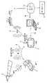
図2aおよび図2bは例として遠隔操縦車両1の異なる2つの実施形態を示している。図2aでは遠隔操縦されるゲーム車両1はレースカーである。このレースカー1はそのルーフに組み込まれたビデオカメラ19を使用することができる。ビデオカメラ19から発信される画像はBlueToothリンク5により携帯操作卓3に送信され、携帯操作卓3の画面上に表示することができる。 2a and 2b show two different embodiments of the remotely piloted
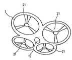
図2bは、遠隔操縦されるゲーム車両1が4枚羽根方式のクワドリコプタ21で構成されることも可能であることを示している。レースカーの場合と同様、クワドリコプタ1も、その中央にあるドーム状のビデオカメラ19を使用することができる。 FIG. 2 b shows that the remotely operated
もちろん遠隔操縦車両1は、たとえば船、オートバイ、戦車など別の乗物の形態をとることもできる。 Of course, the
要約すれば、遠隔操縦車両1は、基本的にセンサを追加しビデオを送信する、制御された車両である。 In summary, the remotely controlled
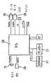
図3aおよび図3bは遠隔操縦車両1の主な電子要素を概略的に示している。 FIGS. 3 a and 3 b schematically show the main electronic elements of the remotely controlled
図3aは基本的な電子構成部品を詳細に示している。ビデオカメラ19、遠隔操縦車両を移動させるのに用いるモータ25、ならびに種々のメモリ27および29など種々の周辺機器に計算ユニット23が接続される。メモリ29は、SDカード、すなわちデジタルデータ保存用のリムーバブルメモリカードである。このカード29は省略することもできるが、カメラ19から発信されるビデオ画像を記録し、記録されたビデオシーケンスを再生できるようにするのがこのカードの機能であるので、残しておくことが好ましい。 FIG. 3a shows the basic electronic components in detail. The
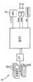
図3bは遠隔操縦車両1に搭載された追加機能を示す。車両1は主に2つの追加機能を備える。すなわち3つの加速度計33および3つのジャイロスコープ35を含む慣性測定装置31と、GPSセンサ37である。 FIG. 3 b shows additional functions installed in the
追加機能はたとえばシリアルリンクにより計算ユニット23に接続される。また、車両1の電子システム内で実行されるソフトウェアを更新することができるよう、車両にUSB(Universal Serial Bus)を追加することもできる。 The additional function is connected to the
慣性測定装置31は車両1の重要な要素である。慣性測定装置により車両の座標値をリアルタイムかつ正確に推定することができる。慣性測定装置は合計で9つの座標値、すなわち空間における車両の位置X、Y、Z、車両の方向角α、β、γ(オイラー角)、ならびに3つの直交軸X、Y、Zのそれぞれにおける速度VX、VY、VZ、を推定する。 The
これらの移動座標値は3つの加速度計33ならびに3つのジャイロスコープ35から出力される。これらの座標値はセンサの測定値の出力側においてカルマンフィルタの後で得られる。より詳細には、マイクロコントローラが測定を行い、シリアルリンクまたはシリアルバス(シリアル周辺インターコネクト、SPI)により計算ユニット23に再送信する。計算ユニット23は主にカルマンろ波を行い、このようにして推定された車両1の位置をBluetooth接続5により操作卓3に送信する。ろ波の計算は最適化することができる。すなわち計算ユニット23は、推進および方向エンジン25に送信されている設定値を承知している。計算ユニットはカルマンフィルタの予測を確立するためにこれらの情報を使用することができる。慣性測定装置31を使用して決定された車両1の瞬間位置は25Hzの周波数で操作卓3に送信される。すなわち操作卓は一画像あたり1つの位置を受信する。 These movement coordinate values are output from the three
計算ユニット23が計算で過負荷になっている場合、慣性測定装置31から出力された生の測定値を操作卓に送信することができ、操作卓は計算ユニット23の代わりに自身でカルマンろ波を行う。ビデオゲームの計算はすべて操作卓3上で行い、データ取得はすべて車両が行うことが好ましいため、システムの単純性および一貫性の点でこの方法は望ましくはないものの、実施可能ではある。 When the
慣性測定装置31のセンサは圧電センサの形態で実施することができる。これらのセンサは温度により大きく変動するが、このことはすなわち、温度センサおよびレオスタットを使用してセンサを一定の温度に保つか、温度センサを使用することによりこれら圧電センサのレベルにおける温度を測定し、ソフトウェアにより温度に対するセンサの変動を補正しなければならないことを意味する。 The sensor of the
GPSセンサ37は遠隔操縦車両1の主要な機能ではない。しかしながらこのセンサにより安価できわめて豊富な機能が得られる。軌跡のリアルタイム追尾は慣性測定装置29によって行われるので、主に屋外で作動し軌跡のリアルタイム追尾を必要としない大衆向けGPSで十分である。また、ソフトウェアGPSを使用することも可能である。操作卓3は市場で入手可能な任意の携帯操作卓である。現在知られている携帯操作卓の例としてはソニーのプレイステーション・ポータブルPSPまたはニンテンドーのニンテンドーDSがある。車両1と無線で交信するために、操作卓にBluetooth端子(ドングル)(図1を参照のこと)を設けることもできる。 The
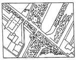
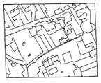
データベース17(図1)は、好ましくは世界中の航空写真のライブラリを含む。衛星、飛行機、ヘリコプタから得られた写真がこれに該当する。図4aから図4cは、データベース17から得ることができる航空写真の種々の例を示す。操作卓3がデータベース17にアクセスできるよう、データベースはインターネットを介してアクセス可能である。 Database 17 (FIG. 1) preferably includes a library of aerial photographs from around the world. This is the case with photos taken from satellites, airplanes and helicopters. FIGS. 4 a to 4 c show various examples of aerial photographs that can be obtained from the
データベース17からダウンロードされた航空写真は、操作卓3上で実行されるビデオゲームに組み込まれる合成ビューポイントを作成するために、操作卓3によって使用される。 The aerial photograph downloaded from the
次に、操作卓3がデータベース17から航空写真を取得する方法について説明する。これを行うために、操作卓3のユーザはその遠隔操縦車両1を、公園または庭など、プレーを所望する実際の場所に置く。GPSセンサ37のおかげで、車両1はその地上座標値を求めることができる。次に、BluetoothまたはWiFi5リンクにより、地上座標値が操作卓3に送信される。すると操作卓3は、インターネットを介したWifi9接続によりデータベース17に接続する。プレーする場所においてWiFi接続がない場合、操作卓3は、求めた地上位置を記憶する。次にプレーヤが、インターネットへのアクセスを持つコンピュータに15まで移動する。プレーヤが操作卓3をコンピュータに接続すると、コンピュータ15を通して、操作卓3とデータベース17の間の接続が間接的に行われる。操作卓3とデータベース17の間の接続が確立すると、地上座標値に対応するデータベース17内の航空写真または地図の検索を行うために、操作卓3によって記憶された地上座標値が使用される。車両1が存在する地上ゾーンを再現する画像がデータベース17で見つかると、操作卓3は見つかった航空写真をダウンロードする。 Next, how the
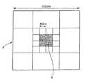
図5は、操作卓3および車両1を前提とするビデオゲーム用に使用される二次元プレーバッググラウンドの幾何的規定例を示す。 FIG. 5 shows a geometric definition example of a two-dimensional playground used for a video game on the premise of the
図5において示す正方形および長方形はデータベース17からダウンロードされた航空写真を表す。集合Aの正方形は9個の中間長方形に分割される。これら9つの中間長方形のうち、中央の長方形自体は16個の正方形に細分される。これら16個の正方形のうち、中央の4つの正方形が本来の意味でのプレーゾーンBを表す。このプレーゾーンBには最大解像度の航空写真をロードすることができ、プレーゾーンBのすぐ外側、すなわち16個の正方形のうちの残りの12個の正方形には、それより解像度が低い航空写真をロードすることができ、細分された中央の長方形の周囲において、細分されていない8個の長方形で表された余白部分には、さらに解像度の低いデータベースの航空写真がロードされる。プレーの中心からの遠近による種々の画像の解像度を調節することにより、操作卓で保存および処理すべきデータ量が最適化されつつ、それらの投射図化による画像効果は影響を受けない。プレーゾーンの中心から最も遠い画像は、その距離に対応する解像度で表示される。 Squares and rectangles shown in FIG. 5 represent aerial photographs downloaded from the
ダウンロードされた航空写真は、対応するビデオゲーム内で使用することができる複数の異なるビューポイントを作成するために操作卓3が使用する。より詳細には、操作卓3が、ダウンロードされた航空写真から、二次元垂直ビューポイント(図6aおよび図6bを参照のこと)ならびに三次元パースペクティブ・ビューポイント(図7aから図7cを参照のこと)など、少なくとも2つの異なるビューポイントを作成することができるようにする。 The downloaded aerial photos are used by the
図6aは操作卓3によってダウンロードされた航空写真を示す。遠隔操縦車両1は、図6aの航空写真によって示される地上のどこかに存在する。この航空写真は図6bに略図で示すような合成画像を作成するのに使用される。長方形39は図6aの航空写真を表す。この長方形には3つのグラフィックオブジェクト41および43が嵌め込まれている。これらのグラフィックオブジェクトはそれぞれ、長方形39で表したプレーゾーン上の遠隔操縦車両の位置(遠隔操縦車両の位置に相当する○43を参照のこと)、ならびにその他の実際または架空の対象物の位置(たとえばビデオゲームの実際の競争相手または架空の敵の位置を表すことができる×41を参照のこと)を表す。 FIG. 6 a shows an aerial photograph downloaded by the
長方形39で規定されるプレーゾーンから車両1が飛び出さないよう車両のソフトウェアに監視させることが可能である。 The vehicle software can be monitored so that the
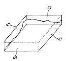
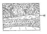
図7aから図7cは、ダウンロードされた航空写真から操作卓3が作成することができるパースペクティブ・ビューポイントを示す。このパースペクティブ画像はダウンロードされた航空写真が挿入された「地面」45を含む。一方、側面47は、図7bに例を示す無限遠パースペクティブ仮想画像である。これらの画像は操作卓3のリアルタイム三次元グラフィックエンジンにより生成される。 Figures 7a to 7c show perspective viewpoints that the
二次元ビューポイントの場合と同様、グラフィックオブジェクト41および43は、プレーヤ自身の車(43)の位置、ならびに同時プレーヤまたは潜在敵(41)の位置をプレーヤに示す。 As with the two-dimensional viewpoint,
ビューポイントの作成に関しては、データベース17から立面図のメッシングをダウンロードすることも可能である。 Regarding the creation of the viewpoint, it is also possible to download the elevation meshing from the
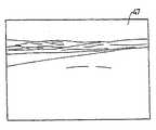
図8は、遠隔操縦車両1に搭載されたビデオカメラ19から発信されるビューポイントなど、ビデオゲームシステム内に設けられている第3のビューポイント49を示す。図8はそのようなビューポイントの例を示す。このビデオの実画像には、プレーヤが使用するビデオゲームに応じて種々の仮想グラフィックオブジェクトが嵌め込まれる。 FIG. 8 shows a
図9は、上で説明したビューポイントがプレーヤに対しどのように表示されるかを要約して示す表示を有する操作卓3を示す。ビデオカメラ19から発信されるビデオ画像に対応するビューポイント49があることがわかる。ビューポイント49は、図9の場合には、仮想サーキットの通行路を規定する仮想道路標示である仮想嵌め込み51を含む。ビューポイント49の中には遠隔操縦車両1の実際のボンネット53も見える。 FIG. 9 shows the
第2のビューポイント55は、図6aおよび図6bに示す二次元垂直ビューポイントに相当する。ビューポイント55は、プレーする場所の航空写真を複製したもので構成され、仮想サーキット57を移動するポイント59を有する仮想のレースサーキット57がそこに嵌め込まれる。このポイント59は遠隔操縦車両1の現在位置を示す。ビデオゲームによっては、二次元ビューポイント55を上で説明したようなパースペクティブ・ビューに置き換えることができる。最後に、図9に示したような表示は、ここでは車両1の仮想燃料計を示す第3のゾーン61を含む。次に、図1に示すビデオゲームシステムのためのビデオゲームの一例について説明する。この例は、遠隔操縦車両1と操作卓3とを使用して実際の地面で行う車のレースであり、このゲームの特徴は、レースサーキットが実際の場所に実際に表示されているわけではなく、車が進む実際のゲームの場所にレースサーキットが仮想的に置かれているだけであることである。 The
ユーザは、レースゲームを初期化するために、上で既に説明した方法で、ユーザのプレー場所に対応する航空写真の取得を行う。操作卓3が、車1があるプレー場所の立面図を再現する航空写真39のダウンロードを終了すると、図10に示すように、ソフトウェアはダウンロードされた航空写真39上に仮想のレースサーキット57を描く。サーキット57は、その仮想スタートラインが車1の地理的位置の近傍の航空写真39上に位置決めされるよう生成される。車1のこの地理的位置はGPSモジュールから出力される座標値に相当し、この位置に、車1の次元についての既知の物理的値が付加される。プレーヤは操作卓3のキー58を使用して、スタートラインを中心としてサーキット57を旋回させること、スタートラインを相似移動の不変点としつつ、サーキット57を相似移動させること(相似移動は、車の操作性に対応する、決められた比率で行われる)、あるいはスタートポイントを中心としてサーキットをスライドさせることができる。 In order to initialize the racing game, the user obtains an aerial photograph corresponding to the user's play location by the method already described above. When the
また、サーキット上でスタートラインをスライドさせるようにすることもできるが、この場合、ゲームを開始するには車はスタートラインに着かなければならない。 You can also make the start line slide on the circuit, but in this case the car must reach the start line to start the game.
プレーヤがビデオゲームを実行しようとする家の庭が、ソフトウェアによって当初描画されたサーキットにとって十分に大きくない場合には、上記のことが有益になることもある。したがってプレーヤは、仮想サーキットが実際のプレー場所にうまく位置決めされるまでこの仮想サーキットの位置を変えることができる。 This may be beneficial if the garden of the house where the player is trying to run a video game is not large enough for the circuit originally drawn by the software. Thus, the player can change the position of the virtual circuit until the virtual circuit is successfully positioned at the actual play location.
たとえばクアドリコプタなど、好ましい適用例の1つであるフライトビデオゲームにおいては、フライングマシンを安定化するためにマシンの慣性測定装置が使用される。操作卓により、たとえば「ホバリング」、「右旋回」、「着陸」など飛行設定値がフライングマシンに送信される。フライングマシンに搭載されたマイクロコントローラのソフトウェアはフライングマシンの操縦翼面を使用する。すなわち、慣性測定装置の測定値を飛行設定値と一致させるために羽根の速度の変更または空力操縦翼面の制御を行う。 In a flight video game, which is one of the preferred applications, for example a quadcopter, machine inertial measuring devices are used to stabilize the flying machine. For example, flight settings such as “hovering”, “right turn”, and “landing” are transmitted to the flying machine by the console. The microcontroller software on the flying machine uses the flying machine control surface. In other words, the blade speed is changed or the aerodynamic control blade surface is controlled in order to make the measured value of the inertial measurement device coincide with the flight setting value.
同様に、自動車タイプのビデオ操作卓の場合、たとえば「右旋回」、「制動」、「1m/秒の速度」などの設定値が操作卓から車のマイクロコンピュータに送信される。 Similarly, in the case of an automobile type video console, for example, set values such as “turn right”, “braking”, and “speed of 1 m / sec” are transmitted from the console to the microcomputer of the car.
ゲーム車両は、たとえばGPSおよび/または加速度計またはジャイロスコープから成る慣性測定装置など、主なセンサを使用することができる。また、ビデオカメラ、車の車輪の回転数の計測手段、ヘリコプタまたは飛行機の速度を推定するための空気圧力センサ、水中深度を測定するための水圧センサ、たとえば駆動または方向制御用の各モータの消費など、搭載電子機器の種々の点における消費電流を測定するためのアナログデジタル変換器など、追加的センサを使用することもできる。 The gaming vehicle can use main sensors such as, for example, inertial measurement devices consisting of GPS and / or accelerometers or gyroscopes. Also, consumption of video cameras, vehicle wheel speed measurement means, air pressure sensors for estimating the speed of helicopters or airplanes, water pressure sensors for measuring underwater depth, for example each motor for drive or direction control Additional sensors can also be used, such as analog-to-digital converters for measuring current consumption at various points of the on-board electronics.
これらの測定値は、ゲームの全シーケンス中、サーキット上におけるゲーム車両の位置を推定するのに用いることができる。 These measurements can be used to estimate the position of the game vehicle on the circuit during the entire game sequence.
主に用いられる測定値は、加速度計および/またはジャイロスコープを備える慣性測定装置の測定値である。ノイズを低減すること、ならびに他のセンサ、カメラ、圧力センサの測定値、モータの消費電流の測定値などと合同させることが可能なたとえばカルマンフィルタなどのフィルタを使用することにより、慣性測定装置の測定値をさらに確実なものにすることができる。 The measurement values used mainly are those of inertial measurement devices with accelerometers and / or gyroscopes. Measurement of inertial measurement devices by reducing noise and using filters such as Kalman filter that can be combined with other sensors, cameras, pressure sensor measurements, motor current consumption measurements, etc. The value can be made more certain.
たとえば、カメラ19から発信されるビデオ画像を使用し、ビデオ画像の好ましくは強コントラスト点である画像内の装飾を表す不動点を基にして動きを推定することにより、車1の推定位置を周期的にリタイミングすることが可能である。不動点までの距離は、既知の三角測量手法により行列を最小化することにより推定することができる。 For example, by using a video image transmitted from the
位置は、GPS、特に衛星信号の位相の測定値を使用する最近のGPSモジュールを使用することにより、より長い距離(およそ50メートル)でリタイミングすることもできる。 The position can also be retimed over longer distances (approximately 50 meters) by using GPS, particularly modern GPS modules that use phase measurements of satellite signals.
ゲーム車両の速度は、たとえばエンコーダホイールを使用して車輪の回転数を計測することにより推定することができる。 The speed of the game vehicle can be estimated, for example, by measuring the number of wheel rotations using an encoder wheel.
ゲーム車両がモータにより駆動される場合、その速度は前記モータの消費量を測定することにより推定することもできる。そのためには種々の回転数におけるモータの効率を知っておく必要があるが、この効率は事前に試験台で測定することができる。 When the game vehicle is driven by a motor, the speed can also be estimated by measuring the consumption of the motor. For this purpose, it is necessary to know the efficiency of the motor at various rotational speeds, but this efficiency can be measured in advance on a test bench.
別の速度推定手段はビデオカメラ19を使用することである。車または飛行機の場合、ビデオカメラ19は不動であるか、その車両の本体に対するビデオカメラの位置が既知であり、その焦点距離も既知である。ゲーム車両のマイクロコントローラは、たとえばH263またはH264符号化を使用し、MPEG4型のビデオ符号化を行う。この符号化は2つのビデオ画像の間における画像の部分集合の運動の予測計算を前提とする。たとえばこの部分集合は16*16ピクセルの正方形とすることができる。運動の予測はハードウェア加速器にて行うことが好ましい。画像の部分集合の動きの全体は、車両の速度についてきわめて良好な測定値を提供する。車両が不動であるときには、画像の部分集合の運動の和は0に近い。車両が直線前進すると、画像の部分集合は、車両の速度に比例する速度で消滅点から遠ざかる。 Another speed estimation means is to use a
カーレースビデオゲームという状況下では、画面は図9に示すように複数の要素に分割される。左の要素49は車1のビデオカメラ19から発信される画像を表示する。右の要素55により、サーキットの地図および競争相手となる車を見ることができる(図9の右上のビューポイントを参照のこと)。 Under the situation of a car racing video game, the screen is divided into a plurality of elements as shown in FIG. The
表示器は(車の縮尺での)実速度を表示することができる。(フォーミュラー1グランプリレースの場合のように)シミュレートできる車の速度またはガソリン消費量など、ゲームのパラメータを追加することができる。 The indicator can display the actual speed (at the scale of the car). Game parameters can be added, such as vehicle speed or gasoline consumption that can be simulated (as in the
ビデオゲームの一環として操作卓はレースを記憶することもできる。使用できる車が1台のみの場合、自分自身を対戦相手として走行することができる。その場合、記憶される周回の際、車の位置の透明三次元画像を表示させるようにすることができる。 As part of the video game, the console can also remember the race. If you can use only one car, you can drive yourself as your opponent. In that case, a transparent three-dimensional image of the position of the car can be displayed during the stored round.
図11は、仮想嵌め込み物51すなわちレースサーキットの標識が、車1に搭載されたビデオカメラのビューポイントに対応する表示49にどのように適合されるかを詳細に示す図である。図11は、テレビレースゲームを実行することにより車1が移動する実際の地面の地形63の側面図である。プレーする場所は平坦ではなく、下り坂および上り坂があることがわかる。地面の傾斜は変化するが、これは矢印65で示してある。 FIG. 11 is a diagram showing in detail how the
その結果、ビデオ画像上のサーキット51の端部の嵌め込みは静止していてはならず、プレーの場所の傾斜に応じて適合しなければならない。この問題に対応するために、車1の慣性測定装置31は車の姿勢センサを有する。慣性測定装置は車1の瞬間姿勢のリアルタイム取得を行う。車の電子ユニット1は姿勢の瞬間値を基にして、2つの値、すなわち地面の傾斜(すなわち姿勢の長時間平均値)およびサーキットの凸凹(すなわち姿勢の短時間平均値)を推定する。ソフトウェアは、表示を補正するため、すなわち図11の矢印67によって示すようなビデオ画像上で嵌め込み道路標示51を移動させるために、傾斜値を使用する。 As a result, the fit of the end of the
また、道路標示51の表示の調整ソフトウェアは学習をするようになっている。車1が仮想サーキット57上で第1周回を行った後は、サーキット全体についての傾斜および凸凹の値が判明し、記憶され、次の周回における傾斜および凸凹を再推定するカルマンフィルタの予測成分において使用される。 The software for adjusting the display of the road marking 51 learns. After the
不連続道路標示のみを表示し、たとえば道路の各側で4個というように少数の道路標示を表示することにより、ビデオ画像への仮想道路標示51の嵌め込み状態を向上することができる。さらに、遠方にある道路標示は違う色にし、あくまでも表示用として、レーンの輪郭の実際の規定には用いないようにすることもできる。さらに、遠方にある道路標示は、近傍にある道路標示よりも間隔を広くすることができる。 By displaying only discontinuous road markings and displaying a small number of road markings such as four on each side of the road, it is possible to improve the fitting state of the
想定する適用例によっては、道路標示51の位置を調節するために、車のローリング、すなわち車の前後方向軸に対する車の傾きがあるなら、それも推定することが必要になることがある。 Depending on the assumed application, in order to adjust the position of the road marking 51, it may be necessary to estimate any rolling of the vehicle, ie, the inclination of the vehicle relative to the longitudinal axis of the vehicle.
サーキットの凸凹の推定は、センサからのデータから傾斜の測定値を抽出する優先度となる。 The estimation of the unevenness of the circuit is a priority for extracting the measured value of the inclination from the data from the sensor.
サーキットが設置される地面の幾何形状を正確に定義するために、ビデオゲームは学習段階を行うことができる。この学習段階は、本来のゲームの前に、操作卓によって制御される低速かつ一定の速度で行われるのが有利である。プレーヤに対しては、センサの測定値が記憶される第一周回を行うことが要求される。周回が終了すると、記憶されたデータから、サーキットのうちの多数の点における立面図の値が抽出される。次に、これらの立面図の値は、ビデオ画像上で仮想道路標示51の位置を正確にセットするためにゲーム中に使用される。 In order to accurately define the geometry of the ground on which the circuit is installed, the video game can perform a learning phase. This learning phase is advantageously performed at a low and constant speed controlled by the console before the original game. The player is required to perform the first round in which the sensor measurement values are stored. When the lap is completed, elevation values at a number of points in the circuit are extracted from the stored data. These elevation values are then used during the game to accurately set the position of the virtual road marking 51 on the video image.
図12aから図12cは、レースゲームが2台または3台の遠隔操縦カー1で行われる時の共通制御系の規定方法を詳細に示す図である。この場合、2人のプレーヤがいて、それぞれが遠隔操縦カー1と携帯操作卓3を持っている。これら2人のプレーヤは、仮想サーキット57上で2台の車1を使ってカーレースをしようとしている。そのような2人でのゲームの初期化は、たとえば、操作卓で「2台」モードを選択することにより行うことができる。こうすることにより、各車1のBluetoothまたはWiFiプロトコルは「相手検索」モードに入る。相手の車が見つかると、各車1は相手が見つかったことを操作卓3に通知する。すると操作卓1のうちの一方が、上で説明したようなサーキットの選択、レース周回数など、ゲームのパラメータの選択を行う。次に双方の操作卓上でカウントダウンが開始される:すなわち両車はBluetoothまたはWiFiプロトコルにより交信する。種々の周辺装置間のやりとりを簡単にする目的から、各車1はその操作卓3とは交信するが、他の車の操作卓とは交信しない。車1同士は座標値をリアルタイムで送信しあい、各車1は自身の座標値ならびに単数または複数の競走相手の車の座標値を、そのパイロット操作卓3に送信する。操作卓上ではサーキット55の表示が車1の位置を示す。 12a to 12c are diagrams showing in detail a method for defining a common control system when a racing game is played by two or three
そのようなカーゲームでは、Bluetoothプロトコルは「スキャッターネット」モードにある。その場合、車のうちの一方は「マスター」となり、これと対になる操作卓は「スレーブ」となり、他方の車も「スレーブ」となる。また車同士はお互いの位置を交換し合う。2台またはそれ以上の台数の遠隔操縦カー1によるそのようなレーシングゲームの場合、ゲームの初期化の際、車1が共通の同一基準系内にセットされることが必要である。図12aから図12cは対応する共通基準系の規定方法を詳細に示す。 In such car games, the Bluetooth protocol is in "scatter net" mode. In that case, one of the cars becomes a “master”, the operator console paired with it becomes a “slave”, and the other car becomes a “slave”. Cars exchange positions with each other. In the case of such a racing game with two or more
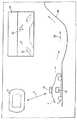
図12aに示すように、ビデオカメラ19を有する遠隔操縦カー1は、実際のゲーム場所にある橋69の正面に位置している。この実際の橋69はスタートラインを表し、4つのLED71を備える。各プレーヤは、少なくとも2つのLED71が自分の操作卓3の画面上に見えるよう車1をセットする。 As shown in FIG. 12a, the
LED71は既知の色をもち、既知の頻度で点滅することができる。こうすることにより、2台のビデオカメラ19からそれぞれ発信されるビデオ画像中でLED71を容易に確認することができる。各車1または各操作卓3上に存在する計算ユニットは画像処理を行い、橋69を基準とする車1のそれぞれの位置を推定する。 The
車1は、橋69を基準とするその位置を推定すると、その位置を他方の車1に送信する。2台の車1がそれぞれ橋69を基準とする位置を推定した後は、車1同士の位置が求められ、レースを開始することができる。 When the
図12bは4つのLED71を示す橋69の前面図である。図12cは、橋69を基準とする車1の位置の判定手順を行う時の操作卓3の表示を示す。図12cで2つの十字73で示してあるように、図12cにおいて、画像処理を行う計算ユニットが、点滅する2つのLED71の検出に成功したことが明確にわかる。 FIG. 12 b is a front view of the
地上を基準とし車同士で共通な基準系をこのように規定することは、(各車がレーシングサーキットに準拠しなければならない)レーシングゲームにとってはきわめて有用である。 It is very useful for racing games (where each car must comply with the racing circuit) to define a common reference system between vehicles based on the ground.
シューティングゲームなど他のビデオゲームの場合、共通基準系の規定はより簡単である。すなわち、各車は競走相手に対する自身の位置を知るだけでよい。 In the case of other video games such as shooting games, the definition of the common reference frame is simpler. That is, each car only needs to know its own position relative to the race opponent.
図13aから図13cは、レーシングビデオゲームの代替版に相当する写真であり、ここではレーシングゲームは単数または複数の車1ではなく、図2bに示すような単数または複数のクワドリコプタ1を前提とするものである。この場合、遠隔操縦される車両1はクワドリコプタであり、慣性測定装置1は、この操作卓の三次元座標値を操作卓3に送信するだけでなく、クワドリコプタ1を安定化するプログラムにとって必要な情報を、クワドリコプタ1に搭載されたプロセッサに供給するために用いられる。 FIGS. 13a to 13c are photographs corresponding to alternative versions of the racing video game, where the racing game is based on one or
クワドリコプタの場合、レースは車の場合のようなレーンではなく三次元である。この場合、レーシングサーキットは、図9に示すように嵌め込まれた仮想道路標示ではなく、たとえば、空間内に浮遊するビデオカメラ19から発信されるビデオ画像(図13b)内に嵌め込まれた仮想円75で示される。プレーヤは仮想円75を通してクワドリコプタ1を操縦しなければならない。 In the case of a quadcopter, the race is three-dimensional, not a lane like a car. In this case, the racing circuit is not a virtual road sign fitted as shown in FIG. 9, but a
車の場合と同様、3つのビュー、すなわち仮想嵌め込みをともなう、ビデオカメラ19から発信されたビデオ画像、ダウンロードされた航空写真に基づく垂直面画像、および同じく衛星画像またはダウンロードされた航空写真に基づくパースペクティブ・ビューが可能である。 As with a car, there are three views: a video image originating from a
図13bは、クワドリコプタによるゲームの際に現れるような嵌め込み仮想円75のビデオ画像の略図である。 FIG. 13b is a schematic illustration of a video image of an inlaying
ダウンロードされた航空写真上でのサーキットの位置決めは、カーレースの場合と同じようにして行われる。サーキットは、障害物および建物に応じて正しく配置されるよう、プレーヤが手動で位置決めする。同様にプレーヤはサーキットを相似変換すること、スタートポイントを中心にして回転させること、レーン上でスタートポイントをスライドさせることができる。サーキット57の位置決めステップを図13aに示す。 The positioning of the circuit on the downloaded aerial photo is done in the same way as in car racing. The circuit is manually positioned by the player so that it is correctly positioned according to obstacles and buildings. Similarly, the player can change the circuit similarity, rotate around the start point, and slide the start point on the lane. The positioning step of the
カーレースの場合と同様、複数のクワドリコプタを前提とするレースについて、たとえば3つの点滅LEDまたは反射要素71を具備するパイロン77など、スタートラインを規定する分離した要素を設ける。クワドリコプタあるいはラジコン飛行機はそのカメラ19の画像のおかげで同じ目印、ならびに点滅するパイロン77の3つのLED71で表される画像内の有意点の中に一列に配置される。すべての幾何パラメータ(カメラの位置、焦点距離など)が既知であるので、車両1はなんの曖昧性もなく共通基準系内に位置決めされる。より詳細には、パイロン77が視野にあるようにして車両1が地面にセットされるよう車両の位置を決め、操作卓3の画面上で3つのLED71が点滅するのを確認する。点滅する3つのLED71は目印の認識のための有意点を表す。既知の頻度でLEDが点滅することにより、ソフトウェアはより容易にこれらがLEDであることを確認することができる。 As in the case of a car race, for a race based on a plurality of quadcopters, a separate element for defining a start line is provided, for example, a
パイロン77を基準とする位置が判明すると、クワドリコプタ1同士は情報を交換し(それぞれがパイロン77を基準として他方の位置につく)、こうして各クワドリコプタは競走相手の位置を推定する。 When the position relative to the
画像処理によりパイロン77の検出が行われたクワドリコプタ1の位置からレースを開始することができる。しかし、慣性測定装置は、レース前のパイロン77を基準とするクワドリコプタ1の当初の位置からのクワドリコプタの移動量を記憶することができるので、別の位置からもレースを開始することが可能であることは言うまでもない。 The race can be started from the position of the
想定される別のゲームは、2台またはそれ以上の台数の車の間でのシューティングゲームである。たとえば、シューティングゲームは、固定ビデオカメラまたはターレット上に設置されたビデオカメラを具備する戦車、あるいはクワドリコプタ、あるは対戦車クワドリコプタを必要とする。この場合、あるサーキットに対する各車両の位置を知る必要はなく、ただ、他の車両に対する各車両の位置を知るだけでよい。より簡単な手順を実施することができる。各車両は、既知の周波数で点滅し、既知の色および/または既知の幾何形状を有するLEDを前もって使用することができる。通信プロトコルにより各車両は、車両の種類、LEDの位置、点滅頻度、LEDの色などについての情報を他の車両と交換する。ゲームの開始時、他方の車両のLEDがビデオセンサ19の視野に入るよう、各車両をセットする。三角測量操作を行うことにより、他方の車両に対する各車両の位置を求めることができる。 Another game envisaged is a shooting game between two or more cars. For example, a shooter game requires a tank with a fixed video camera or a video camera installed on the turret, or a quadricopter, or an anti-tank quadcopter. In this case, it is not necessary to know the position of each vehicle with respect to a certain circuit, it is only necessary to know the position of each vehicle with respect to another vehicle. A simpler procedure can be implemented. Each vehicle can pre-use LEDs that flash at a known frequency and have a known color and / or a known geometry. Each vehicle exchanges information about the type of vehicle, the position of the LED, the blinking frequency, the color of the LED, and the like with other vehicles according to the communication protocol. At the start of the game, each vehicle is set so that the LED of the other vehicle is in the field of view of the
これでゲームを開始することができる。各車両は、慣性測定装置およびその他の測定手段があるおかげで自分の位置および動きがわかる。各車両はこの位置および動きを他の車両に送信する。 The game can now be started. Each vehicle knows its position and movement thanks to inertial measuring devices and other measuring means. Each vehicle transmits this position and movement to other vehicles.
ビデオ操作卓上では、ファインダの画像が、各車両から送信されてくるビデオ画像のたとえば中心に嵌め込まれる。プレーヤは弾丸のシューティングの設定値を別の車両に与えることができる。 On the video console, the viewfinder image is fitted, for example, at the center of the video image transmitted from each vehicle. The player can give bullet shooting settings to another vehicle.
発射する機体のソフトウェアは、シューティング時、他の機体から再送されてきた位置、自分の位置、向きおよび速度を知った上で、シューティングがその的に到達したかどうかを推定することができる。シューティングは、ただちにターゲットに到達する弾丸をシミュレートすることも、弾薬の放物線軌跡または誘導ミサイルの経路をシミュレートすることもできる。シューティングを行う車両の初速、弾丸の速度、たとえば大気条件など外部パラメータなどをシミュレートすることができる。このようにしてビデオゲームのシューティングを多かれ少なかれ複雑なものにすることができる。ミサイル弾薬、曳光弾などの軌跡は操作卓上で重ね合せ表示することができる。 When shooting, the software of the launching aircraft knows the position retransmitted from the other aircraft, its own position, orientation and speed, and can estimate whether the shooting has reached its target. The shooter can simulate a bullet that reaches the target immediately, or a parabolic trajectory of ammunition or a guided missile path. It is possible to simulate the initial speed of a vehicle to be shot, the speed of a bullet, and external parameters such as atmospheric conditions. In this way video game shooting can be made more or less complex. Trajectories such as missile ammunition and fluorescent bullets can be overlaid on the console.
地上走行体または飛行機などの乗物は、ゲーム内の他の乗物の位置も推定することができる。これはカメラ19の画像を使用する形状認識アルゴリズムにより行うことができる。そうでない場合には、たとえばLEDのように識別を可能にする部分を乗物に備えることができる。これらの部分により、他の乗物は、無線手段から送信される慣性測定装置の情報に加え、自分の位置を常時推定することができる。これによりゲームはよりリアルになる。たとえば相互チェーシングゲームの際、プレーヤのうちの1人が、たとえば木など、道路の具体的対象物の後ろに隠れることができる。ビデオゲームは、たとえ無線手段により相手の位置を無線手段により知らされていても、ビデオ画像上でこれを示すことができず、たとえシューティングが良好な方向にあってもシューティングを無効にする。 Vehicles such as ground vehicles or airplanes can also estimate the position of other vehicles in the game. This can be done by a shape recognition algorithm using the image of the
車両が打撃を受けたことを操作卓から知らされたとき、あるいはたとえば燃料切れ、故障、または大気条件のシミュレーションなど、別のゲーム動作とき、ビデオゲームのシナリオに特有な一連のシミュレーションを起動することができる。たとえばクワドリコプタの場合、シナリオは、振動の開始、直線飛行をしなくなること、または緊急着陸となる。戦車の場合、破損、走行速度の低下をシミュレートするか、ターレットがロックされる状態をシミュレートすることができる。ビデオ送信も改変することができ、たとえば受信画像が乱れたり暗くなったりするようにすること、あるいはコックピットガラスの破損のような効果をビデオ画像に嵌め込むことができる。 Activating a series of simulations specific to video game scenarios when the console informs you that the vehicle has been hit or when another game action is performed, for example, simulation of running out of fuel, failure, or atmospheric conditions Can do. For example, in the case of a quadricopter, the scenario is the start of vibration, no straight flight, or an emergency landing. In the case of a tank, it can simulate damage, a decrease in travel speed, or a turret lock condition. The video transmission can also be modified, for example to make the received image turbulent or dark, or effects such as broken cockpit glass can be incorporated into the video image.
本発明によるビデオゲームは
− プレーヤのアクション、すなわち乗物の操縦
− 仮想要素、すなわち操作卓上に表示されるサーキットまたは敵
− シミュレーション、すなわちたとえばエンジンの故障および乗物の速度制限または操縦が著しくむずかしい状態など、ビデオゲームの挙動を変えるためにビデオゲームに送信される命令
を混在させることができる。Video games according to the present invention include:-player actions, i.e. vehicle steering-virtual elements, i.e. circuits or enemies displayed on the console-simulations i.e. engine failure and vehicle speed limits or situations where maneuvering is extremely difficult, etc. Instructions sent to the video game can be mixed to change the behavior of the video game.
これら3つの対話レベルにより、操作卓上のビデオゲームと、センサおよびビデオカメラを具備するゲーム車両との間のリアル感を増大させることができる。 These three levels of interaction can increase the realism between the video game on the console and the game vehicle with the sensor and video camera.
Claims (9)
Translated fromJapanese車両(1)の姿勢のセンサ(31)を有する遠隔操縦車両(1)と、
表示ユニットを備え、サーキット(57)上の車両(1)を遠隔操縦するのに用いられる電子エンティティ(3)と
を備え、
センサ(31)を介して車両(1)の瞬間姿勢を動的に取得するステップと、
センサ(31)から出力される瞬間姿勢の値を基にしてサーキット(57)の少なくとも1つの傾斜パラメータを動的に推定するステップと、
サーキット(57)の単数(複数)の傾斜パラメータの値に応じて電子エンティティの表示(49)を調整するステップと
を含むことを特徴とする方法。A display adjustment method (49) for a video game system (1, 3) comprising:
A remotely operated vehicle (1) having a sensor (31) for attitude of the vehicle (1);
An electronic entity (3) comprising a display unit and used for remotely maneuvering the vehicle (1) on the circuit (57),
Dynamically acquiring the instantaneous posture of the vehicle (1) via the sensor (31);
Dynamically estimating at least one tilt parameter of the circuit (57) based on the instantaneous attitude value output from the sensor (31);
Adjusting the display (49) of the electronic entity in response to the value of the singular parameter (s) of the circuit (57).
サーキット(57)の単数(複数)の傾斜パラメータの推定を精密化するために記憶値を使用するステップと
による学習ルーチンをさらに含む、請求項1乃至3のいずれか1項に記載の方法。Storing an estimate of the single (plurality) of inclination parameters corresponding to the circuit (57) lap;
A method according to any one of the preceding claims, further comprising: a learning routine comprising: using stored values to refine the estimation of the slope parameter (s) of the circuit (57).
Applications Claiming Priority (2)
| Application Number | Priority Date | Filing Date | Title |
|---|---|---|---|
| FR0609776AFR2908324B1 (en) | 2006-11-09 | 2006-11-09 | DISPLAY ADJUSTMENT METHOD FOR VIDEO GAMING SYSTEM |
| PCT/FR2007/001750WO2008056051A2 (en) | 2006-11-09 | 2007-10-24 | Display adjustment method for a video game system |
Publications (1)
| Publication Number | Publication Date |
|---|---|
| JP2010509946Atrue JP2010509946A (en) | 2010-04-02 |
Family
ID=37797488
Family Applications (1)
| Application Number | Title | Priority Date | Filing Date |
|---|---|---|---|
| JP2009535765APendingJP2010509946A (en) | 2006-11-09 | 2007-10-24 | Display adjustment method for video game system |
Country Status (5)
| Country | Link |
|---|---|
| US (1) | US20100009735A1 (en) |
| EP (1) | EP2079537A2 (en) |
| JP (1) | JP2010509946A (en) |
| FR (1) | FR2908324B1 (en) |
| WO (1) | WO2008056051A2 (en) |
Cited By (5)
| Publication number | Priority date | Publication date | Assignee | Title |
|---|---|---|---|---|
| JP2012509812A (en)* | 2008-11-27 | 2012-04-26 | パロット | Device for maneuvering drone |
| JP2015531175A (en)* | 2012-05-22 | 2015-10-29 | オトイ、インコーポレイテッド | Portable mobile lighting stage |
| JP2016211973A (en)* | 2015-05-08 | 2016-12-15 | 富士通株式会社 | Information processing device, information processing program, information processing method, terminal device, setting method, setting program |
| JP2018140686A (en)* | 2017-02-27 | 2018-09-13 | 日本電産コパル株式会社 | Mobile body device and mobile body system |
| WO2020105147A1 (en)* | 2018-11-21 | 2020-05-28 | 楽天株式会社 | Flight path guide system, flight path guide device, and flight path guide method |
Families Citing this family (15)
| Publication number | Priority date | Publication date | Assignee | Title |
|---|---|---|---|---|
| US8939840B2 (en) | 2009-07-29 | 2015-01-27 | Disney Enterprises, Inc. | System and method for playsets using tracked objects and corresponding virtual worlds |
| TWM406889U (en) | 2010-12-29 | 2011-07-01 | Puu Jiuh Co Ltd | Remote control transmitter attached to portable touch-controlled communication device |
| FR2973256B1 (en)* | 2011-03-29 | 2013-05-10 | Parrot | METHOD FOR DETECTING USER-APPLIED SOLICITATION FROM A DRONE TO PRODUCE A PASSING MARKER |
| US9004973B2 (en) | 2012-10-05 | 2015-04-14 | Qfo Labs, Inc. | Remote-control flying copter and method |
| US20140201205A1 (en)* | 2013-01-14 | 2014-07-17 | Disney Enterprises, Inc. | Customized Content from User Data |
| US20140357357A1 (en)* | 2013-05-30 | 2014-12-04 | Microsoft Corporation | Game bundle package |
| CN105148513B (en)* | 2015-09-23 | 2017-06-06 | 腾讯科技(深圳)有限公司 | The operating method and device of Intelligent hardware |
| US10258888B2 (en) | 2015-11-23 | 2019-04-16 | Qfo Labs, Inc. | Method and system for integrated real and virtual game play for multiple remotely-controlled aircraft |
| FR3052084B1 (en) | 2016-06-03 | 2018-07-13 | Drobot X | SYSTEM FOR CONTROLLING THE EVOLUTION OF REMOTE CONTROLS |
| KR20180010884A (en)* | 2016-07-22 | 2018-01-31 | 삼성전자주식회사 | Method, storage medium and electronic device for controlling unmanned aerial vehicle |
| EP3285148A1 (en) | 2016-08-19 | 2018-02-21 | Bigben Interactive SA | Method for controlling a display element by a game console |
| JP6855348B2 (en)* | 2017-07-31 | 2021-04-07 | 株式会社ソニー・インタラクティブエンタテインメント | Information processing device and download processing method |
| EP3444016A1 (en)* | 2017-08-17 | 2019-02-20 | Bigben Interactive SA | Method for controlling a display element by a game console |
| CN114681916A (en)* | 2020-12-28 | 2022-07-01 | 比亚迪股份有限公司 | Game scene determining method, electronic device and storage medium |
| US12002371B2 (en)* | 2021-05-14 | 2024-06-04 | Rockwell Collins, Inc. | Neuromorphic cameras for aircraft |
Citations (5)
| Publication number | Priority date | Publication date | Assignee | Title |
|---|---|---|---|---|
| JPS63277081A (en)* | 1987-05-08 | 1988-11-15 | 株式会社 アスキ− | Game apparatus |
| JPH07110301B2 (en)* | 1988-07-21 | 1995-11-29 | 株式会社セガ・エンタープライゼス | Circuit game equipment |
| JPH11309269A (en)* | 1998-04-27 | 1999-11-09 | Sony Corp | Game device, simulation apparatus and game imade display method |
| US20040110565A1 (en)* | 2002-12-04 | 2004-06-10 | Louis Levesque | Mobile electronic video game |
| JP2005208857A (en)* | 2004-01-21 | 2005-08-04 | Campus Create Co Ltd | Method for generating image |
Family Cites Families (14)
| Publication number | Priority date | Publication date | Assignee | Title |
|---|---|---|---|---|
| KR100305354B1 (en)* | 1997-10-28 | 2002-10-04 | 가부시끼가이샤 에스 엔 케이 | Game device and game system |
| JP2000024160A (en)* | 1998-07-16 | 2000-01-25 | Futaba Corp | Golf course operation control system |
| US6309306B1 (en)* | 1999-03-03 | 2001-10-30 | Disney Enterprises, Inc. | Interactive entertainment attraction using telepresence vehicles |
| DE19921675A1 (en)* | 1999-05-11 | 2000-11-16 | Hornung Hans Georg | Method for acquiring parameters and measured quantities of battery packs and the like |
| US6752720B1 (en)* | 2000-06-15 | 2004-06-22 | Intel Corporation | Mobile remote control video gaming system |
| US6439956B1 (en)* | 2000-11-13 | 2002-08-27 | Interact Accessories, Inc. | RC car device |
| US6735435B2 (en)* | 2001-03-30 | 2004-05-11 | Motorola, Inc. | Method for providing entertainment to portable device based upon predetermined parameters |
| US20040054481A1 (en)* | 2002-09-18 | 2004-03-18 | Lovett J. Timothy | Airspeed indicator with quantitative voice output |
| US7072792B2 (en)* | 2002-12-24 | 2006-07-04 | Daniel Freifeld | Racecourse lap counter and racecourse for radio controlled vehicles |
| FR2849522B1 (en)* | 2002-12-27 | 2008-01-18 | Sgtd | DEVICE FOR A REDUCED MODEL OF A REMOTE PILOT VEHICLE USING A REMOTE CONTROL |
| US7704119B2 (en)* | 2004-02-19 | 2010-04-27 | Evans Janet E | Remote control game system with selective component disablement |
| US7593821B2 (en)* | 2004-11-23 | 2009-09-22 | Lg Chem, Ltd. | Method and system for joint battery state and parameter estimation |
| US7650207B2 (en)* | 2005-05-04 | 2010-01-19 | Lockheed Martin Corp. | Locomotive/train navigation system and method |
| US7211980B1 (en)* | 2006-07-05 | 2007-05-01 | Battelle Energy Alliance, Llc | Robotic follow system and method |
- 2006
- 2006-11-09FRFR0609776Apatent/FR2908324B1/ennot_activeExpired - Fee Related
- 2007
- 2007-10-24EPEP07866424Apatent/EP2079537A2/ennot_activeWithdrawn
- 2007-10-24WOPCT/FR2007/001750patent/WO2008056051A2/enactiveApplication Filing
- 2007-10-24JPJP2009535765Apatent/JP2010509946A/enactivePending
- 2007-10-24USUS12/446,621patent/US20100009735A1/ennot_activeAbandoned
Patent Citations (5)
| Publication number | Priority date | Publication date | Assignee | Title |
|---|---|---|---|---|
| JPS63277081A (en)* | 1987-05-08 | 1988-11-15 | 株式会社 アスキ− | Game apparatus |
| JPH07110301B2 (en)* | 1988-07-21 | 1995-11-29 | 株式会社セガ・エンタープライゼス | Circuit game equipment |
| JPH11309269A (en)* | 1998-04-27 | 1999-11-09 | Sony Corp | Game device, simulation apparatus and game imade display method |
| US20040110565A1 (en)* | 2002-12-04 | 2004-06-10 | Louis Levesque | Mobile electronic video game |
| JP2005208857A (en)* | 2004-01-21 | 2005-08-04 | Campus Create Co Ltd | Method for generating image |
Cited By (8)
| Publication number | Priority date | Publication date | Assignee | Title |
|---|---|---|---|---|
| JP2012509812A (en)* | 2008-11-27 | 2012-04-26 | パロット | Device for maneuvering drone |
| JP2015531175A (en)* | 2012-05-22 | 2015-10-29 | オトイ、インコーポレイテッド | Portable mobile lighting stage |
| US9609284B2 (en) | 2012-05-22 | 2017-03-28 | Otoy, Inc. | Portable mobile light stage |
| JP2016211973A (en)* | 2015-05-08 | 2016-12-15 | 富士通株式会社 | Information processing device, information processing program, information processing method, terminal device, setting method, setting program |
| JP2018140686A (en)* | 2017-02-27 | 2018-09-13 | 日本電産コパル株式会社 | Mobile body device and mobile body system |
| WO2020105147A1 (en)* | 2018-11-21 | 2020-05-28 | 楽天株式会社 | Flight path guide system, flight path guide device, and flight path guide method |
| JPWO2020105147A1 (en)* | 2018-11-21 | 2021-02-15 | 楽天株式会社 | Flight route guidance system, flight route guidance device and flight route guidance method |
| US12230144B2 (en) | 2018-11-21 | 2025-02-18 | Rakuten Group, Inc. | Flight route guidance system, flight route guidance device and flight route guidance method |
Also Published As
| Publication number | Publication date |
|---|---|
| US20100009735A1 (en) | 2010-01-14 |
| FR2908324A1 (en) | 2008-05-16 |
| EP2079537A2 (en) | 2009-07-22 |
| WO2008056051A3 (en) | 2008-07-03 |
| WO2008056051A2 (en) | 2008-05-15 |
| FR2908324B1 (en) | 2009-01-16 |
Similar Documents
| Publication | Publication Date | Title |
|---|---|---|
| JP2010509946A (en) | Display adjustment method for video game system | |
| JP2010509665A (en) | Game zone definition method for video game system | |
| JP2010508930A (en) | Common Reference System Definition Method for Video Game Systems | |
| US20200001188A1 (en) | System and method for integrated real and virtual game play for multiple remotely-controlled aircraft | |
| JP6253218B2 (en) | Entertainment system and method | |
| KR101748401B1 (en) | Method for controlling virtual reality attraction and system thereof | |
| KR20100137413A (en) | Mobile body competition implementation system | |
| CN109478340A (en) | Simulation system, processing method, and information storage medium | |
| US20080125224A1 (en) | Method and apparatus for controlling simulated in flight realistic and non realistic object effects by sensing rotation of a hand-held controller | |
| JP2004503307A (en) | Mobile remote control video game system | |
| KR20200032547A (en) | Device of augmented reality games for self-driving vehicles and method for the same | |
| JP7440776B2 (en) | Game programs, computers, and game systems | |
| JP2023171563A (en) | Game programs, game devices, and game systems | |
| JP6974780B2 (en) | Game programs, computers, and game systems | |
| CN116558360A (en) | Shooting simulation training method and system based on sports vehicle | |
| JPH06277362A (en) | Three-dimensional game device | |
| JP2002224434A (en) | Image synthesis device, virtual experience device, and image synthesis method | |
| JPH10277261A (en) | Image synthesis device and virtual experience device using the same | |
| US20250032926A1 (en) | Method and system for mixed-reality race game | |
| CN109584669A (en) | More field vehicle based on AR technology fights emulation platform | |
| JPH113437A (en) | Image synthesizing apparatus and image synthesizing method | |
| JP7082302B2 (en) | Game programs, game devices, and game systems | |
| WO2025022357A1 (en) | Method and system for mixed-reality race game | |
| Schulz | Proseminar-Augmented Reality in Computer Games | |
| NZ561260A (en) | Vehicle competition implementation system |
Legal Events
| Date | Code | Title | Description |
|---|---|---|---|
| A621 | Written request for application examination | Free format text:JAPANESE INTERMEDIATE CODE: A621 Effective date:20101020 | |
| RD04 | Notification of resignation of power of attorney | Free format text:JAPANESE INTERMEDIATE CODE: A7424 Effective date:20120710 | |
| A131 | Notification of reasons for refusal | Free format text:JAPANESE INTERMEDIATE CODE: A131 Effective date:20121016 | |
| A02 | Decision of refusal | Free format text:JAPANESE INTERMEDIATE CODE: A02 Effective date:20130404 |