JP2010508911A - Apparatus and method for providing surgical access to the spine - Google Patents
Apparatus and method for providing surgical access to the spineDownload PDFInfo
- Publication number
- JP2010508911A JP2010508911AJP2009535492AJP2009535492AJP2010508911AJP 2010508911 AJP2010508911 AJP 2010508911AJP 2009535492 AJP2009535492 AJP 2009535492AJP 2009535492 AJP2009535492 AJP 2009535492AJP 2010508911 AJP2010508911 AJP 2010508911A
- Authority
- JP
- Japan
- Prior art keywords
- curved
- cannula
- path
- arcuate
- guide member
- Prior art date
- Legal status (The legal status is an assumption and is not a legal conclusion. Google has not performed a legal analysis and makes no representation as to the accuracy of the status listed.)
- Withdrawn
Links
- 238000000034methodMethods0.000titleclaimsdescription89
- 239000007943implantSubstances0.000claimsabstractdescription124
- 210000000988bone and boneAnatomy0.000claimsabstractdescription20
- 238000012360testing methodMethods0.000claimsabstractdescription20
- 210000001519tissueAnatomy0.000claimsabstractdescription20
- 239000000523sampleSubstances0.000claimsabstractdescription12
- 239000004575stoneSubstances0.000claimsabstractdescription10
- 238000013459approachMethods0.000claimsdescription43
- 230000000399orthopedic effectEffects0.000claimsdescription27
- 238000001356surgical procedureMethods0.000claimsdescription22
- 230000007246mechanismEffects0.000claimsdescription20
- 230000004927fusionEffects0.000claimsdescription19
- 238000011282treatmentMethods0.000claimsdescription11
- 230000008859changeEffects0.000claimsdescription5
- 238000002360preparation methodMethods0.000claimsdescription5
- 210000000278spinal cordAnatomy0.000claimsdescription5
- 230000008878couplingEffects0.000claimsdescription3
- 238000010168coupling processMethods0.000claimsdescription3
- 238000005859coupling reactionMethods0.000claimsdescription3
- 238000005452bendingMethods0.000claimsdescription2
- 238000002513implantationMethods0.000claims1
- 230000000977initiatory effectEffects0.000claims1
- 238000007493shaping processMethods0.000claims1
- 238000003780insertionMethods0.000abstractdescription22
- 230000037431insertionEffects0.000abstractdescription22
- 241001631457CannulaSpecies0.000abstractdescription14
- 210000003195fasciaAnatomy0.000abstractdescription7
- -1TampsSubstances0.000abstractdescription3
- 230000037361pathwayEffects0.000abstractdescription3
- 230000000149penetrating effectEffects0.000description13
- 210000005036nerveAnatomy0.000description11
- 230000006835compressionEffects0.000description9
- 238000007906compressionMethods0.000description9
- 230000006870functionEffects0.000description8
- 239000000463materialSubstances0.000description8
- 230000006837decompressionEffects0.000description7
- 230000014759maintenance of locationEffects0.000description7
- 238000007747platingMethods0.000description6
- 230000000087stabilizing effectEffects0.000description6
- 230000000712assemblyEffects0.000description5
- 238000000429assemblyMethods0.000description5
- 230000008569processEffects0.000description5
- 230000000694effectsEffects0.000description4
- 239000000203mixtureSubstances0.000description4
- 238000012544monitoring processMethods0.000description4
- 210000003205muscleAnatomy0.000description4
- 230000006641stabilisationEffects0.000description4
- 238000011105stabilizationMethods0.000description4
- 208000002193PainDiseases0.000description3
- 239000000853adhesiveSubstances0.000description3
- 230000001070adhesive effectEffects0.000description3
- 238000001574biopsyMethods0.000description3
- 238000002567electromyographyMethods0.000description3
- 238000012423maintenanceMethods0.000description3
- 238000011084recoveryMethods0.000description3
- 230000008439repair processEffects0.000description3
- 210000004872soft tissueAnatomy0.000description3
- 208000024891symptomDiseases0.000description3
- 208000007623LordosisDiseases0.000description2
- 238000004873anchoringMethods0.000description2
- 210000001951dura materAnatomy0.000description2
- 238000001125extrusionMethods0.000description2
- 230000002792vascularEffects0.000description2
- 210000005166vasculatureAnatomy0.000description2
- 208000004044HypesthesiaDiseases0.000description1
- 206010023509KyphosisDiseases0.000description1
- 208000001132OsteoporosisDiseases0.000description1
- 208000004550Postoperative PainDiseases0.000description1
- 208000012287ProlapseDiseases0.000description1
- 206010037779RadiculopathyDiseases0.000description1
- 208000007103SpondylolisthesisDiseases0.000description1
- XAGFODPZIPBFFR-UHFFFAOYSA-NaluminiumChemical compound[Al]XAGFODPZIPBFFR-UHFFFAOYSA-N0.000description1
- 229910052782aluminiumInorganic materials0.000description1
- 230000009286beneficial effectEffects0.000description1
- 230000002146bilateral effectEffects0.000description1
- 229920000249biocompatible polymerPolymers0.000description1
- 230000015572biosynthetic processEffects0.000description1
- 239000008280bloodSubstances0.000description1
- 210000004369bloodAnatomy0.000description1
- 239000002639bone cementSubstances0.000description1
- 208000015322bone marrow diseaseDiseases0.000description1
- 239000004568cementSubstances0.000description1
- 239000000919ceramicSubstances0.000description1
- 210000003710cerebral cortexAnatomy0.000description1
- 238000012937correctionMethods0.000description1
- 230000003247decreasing effectEffects0.000description1
- 230000010339dilationEffects0.000description1
- 201000010099diseaseDiseases0.000description1
- 208000037265diseases, disorders, signs and symptomsDiseases0.000description1
- 229920001971elastomerPolymers0.000description1
- 239000000806elastomerSubstances0.000description1
- 230000002349favourable effectEffects0.000description1
- 239000012634fragmentSubstances0.000description1
- 208000034783hypoesthesiaDiseases0.000description1
- 210000004446longitudinal ligamentAnatomy0.000description1
- 230000007659motor functionEffects0.000description1
- 230000004118muscle contractionEffects0.000description1
- 210000000944nerve tissueAnatomy0.000description1
- 231100000862numbnessToxicity0.000description1
- 239000013307optical fiberSubstances0.000description1
- 210000000056organAnatomy0.000description1
- 230000007170pathologyEffects0.000description1
- 230000035515penetrationEffects0.000description1
- 229920003229poly(methyl methacrylate)Polymers0.000description1
- 239000004926polymethyl methacrylateSubstances0.000description1
- 230000003014reinforcing effectEffects0.000description1
- 206010039722scoliosisDiseases0.000description1
- 230000037152sensory functionEffects0.000description1
- 230000008961swellingEffects0.000description1
- 230000001225therapeutic effectEffects0.000description1
- 238000002560therapeutic procedureMethods0.000description1
- 238000012800visualizationMethods0.000description1
Images


Classifications
- A—HUMAN NECESSITIES
- A61—MEDICAL OR VETERINARY SCIENCE; HYGIENE
- A61B—DIAGNOSIS; SURGERY; IDENTIFICATION
- A61B17/00—Surgical instruments, devices or methods
- A61B17/02—Surgical instruments, devices or methods for holding wounds open, e.g. retractors; Tractors
- A61B17/025—Joint distractors
- A—HUMAN NECESSITIES
- A61—MEDICAL OR VETERINARY SCIENCE; HYGIENE
- A61B—DIAGNOSIS; SURGERY; IDENTIFICATION
- A61B17/00—Surgical instruments, devices or methods
- A61B17/56—Surgical instruments or methods for treatment of bones or joints; Devices specially adapted therefor
- A61B17/58—Surgical instruments or methods for treatment of bones or joints; Devices specially adapted therefor for osteosynthesis, e.g. bone plates, screws or setting implements
- A61B17/68—Internal fixation devices, including fasteners and spinal fixators, even if a part thereof projects from the skin
- A61B17/70—Spinal positioners or stabilisers, e.g. stabilisers comprising fluid filler in an implant
- A—HUMAN NECESSITIES
- A61—MEDICAL OR VETERINARY SCIENCE; HYGIENE
- A61B—DIAGNOSIS; SURGERY; IDENTIFICATION
- A61B17/00—Surgical instruments, devices or methods
- A61B17/16—Instruments for performing osteoclasis; Drills or chisels for bones; Trepans
- A61B17/1604—Chisels; Rongeurs; Punches; Stamps
- A61B17/1606—Chisels; Rongeurs; Punches; Stamps of forceps type, i.e. having two jaw elements moving relative to each other
- A61B17/1608—Chisels; Rongeurs; Punches; Stamps of forceps type, i.e. having two jaw elements moving relative to each other the two jaw elements being linked to two elongated shaft elements moving longitudinally relative to each other
- A61B17/1611—Chisels; Rongeurs; Punches; Stamps of forceps type, i.e. having two jaw elements moving relative to each other the two jaw elements being linked to two elongated shaft elements moving longitudinally relative to each other the two jaw elements being integral with respective elongate shaft elements
- A—HUMAN NECESSITIES
- A61—MEDICAL OR VETERINARY SCIENCE; HYGIENE
- A61B—DIAGNOSIS; SURGERY; IDENTIFICATION
- A61B17/00—Surgical instruments, devices or methods
- A61B17/16—Instruments for performing osteoclasis; Drills or chisels for bones; Trepans
- A61B17/1642—Instruments for performing osteoclasis; Drills or chisels for bones; Trepans for producing a curved bore
- A—HUMAN NECESSITIES
- A61—MEDICAL OR VETERINARY SCIENCE; HYGIENE
- A61B—DIAGNOSIS; SURGERY; IDENTIFICATION
- A61B17/00—Surgical instruments, devices or methods
- A61B17/16—Instruments for performing osteoclasis; Drills or chisels for bones; Trepans
- A61B17/1659—Surgical rasps, files, planes, or scrapers
- A—HUMAN NECESSITIES
- A61—MEDICAL OR VETERINARY SCIENCE; HYGIENE
- A61B—DIAGNOSIS; SURGERY; IDENTIFICATION
- A61B17/00—Surgical instruments, devices or methods
- A61B17/16—Instruments for performing osteoclasis; Drills or chisels for bones; Trepans
- A61B17/17—Guides or aligning means for drills, mills, pins or wires
- A61B17/1739—Guides or aligning means for drills, mills, pins or wires specially adapted for particular parts of the body
- A61B17/1757—Guides or aligning means for drills, mills, pins or wires specially adapted for particular parts of the body for the spine
- A—HUMAN NECESSITIES
- A61—MEDICAL OR VETERINARY SCIENCE; HYGIENE
- A61B—DIAGNOSIS; SURGERY; IDENTIFICATION
- A61B17/00—Surgical instruments, devices or methods
- A61B17/34—Trocars; Puncturing needles
- A61B17/3468—Trocars; Puncturing needles for implanting or removing devices, e.g. prostheses, implants, seeds, wires
- A—HUMAN NECESSITIES
- A61—MEDICAL OR VETERINARY SCIENCE; HYGIENE
- A61F—FILTERS IMPLANTABLE INTO BLOOD VESSELS; PROSTHESES; DEVICES PROVIDING PATENCY TO, OR PREVENTING COLLAPSING OF, TUBULAR STRUCTURES OF THE BODY, e.g. STENTS; ORTHOPAEDIC, NURSING OR CONTRACEPTIVE DEVICES; FOMENTATION; TREATMENT OR PROTECTION OF EYES OR EARS; BANDAGES, DRESSINGS OR ABSORBENT PADS; FIRST-AID KITS
- A61F2/00—Filters implantable into blood vessels; Prostheses, i.e. artificial substitutes or replacements for parts of the body; Appliances for connecting them with the body; Devices providing patency to, or preventing collapsing of, tubular structures of the body, e.g. stents
- A61F2/02—Prostheses implantable into the body
- A61F2/30—Joints
- A61F2/44—Joints for the spine, e.g. vertebrae, spinal discs
- A61F2/4455—Joints for the spine, e.g. vertebrae, spinal discs for the fusion of spinal bodies, e.g. intervertebral fusion of adjacent spinal bodies, e.g. fusion cages
- A—HUMAN NECESSITIES
- A61—MEDICAL OR VETERINARY SCIENCE; HYGIENE
- A61F—FILTERS IMPLANTABLE INTO BLOOD VESSELS; PROSTHESES; DEVICES PROVIDING PATENCY TO, OR PREVENTING COLLAPSING OF, TUBULAR STRUCTURES OF THE BODY, e.g. STENTS; ORTHOPAEDIC, NURSING OR CONTRACEPTIVE DEVICES; FOMENTATION; TREATMENT OR PROTECTION OF EYES OR EARS; BANDAGES, DRESSINGS OR ABSORBENT PADS; FIRST-AID KITS
- A61F2/00—Filters implantable into blood vessels; Prostheses, i.e. artificial substitutes or replacements for parts of the body; Appliances for connecting them with the body; Devices providing patency to, or preventing collapsing of, tubular structures of the body, e.g. stents
- A61F2/02—Prostheses implantable into the body
- A61F2/30—Joints
- A61F2/46—Special tools for implanting artificial joints
- A61F2/4601—Special tools for implanting artificial joints for introducing bone substitute, for implanting bone graft implants or for compacting them in the bone cavity
- A—HUMAN NECESSITIES
- A61—MEDICAL OR VETERINARY SCIENCE; HYGIENE
- A61F—FILTERS IMPLANTABLE INTO BLOOD VESSELS; PROSTHESES; DEVICES PROVIDING PATENCY TO, OR PREVENTING COLLAPSING OF, TUBULAR STRUCTURES OF THE BODY, e.g. STENTS; ORTHOPAEDIC, NURSING OR CONTRACEPTIVE DEVICES; FOMENTATION; TREATMENT OR PROTECTION OF EYES OR EARS; BANDAGES, DRESSINGS OR ABSORBENT PADS; FIRST-AID KITS
- A61F2/00—Filters implantable into blood vessels; Prostheses, i.e. artificial substitutes or replacements for parts of the body; Appliances for connecting them with the body; Devices providing patency to, or preventing collapsing of, tubular structures of the body, e.g. stents
- A61F2/02—Prostheses implantable into the body
- A61F2/30—Joints
- A61F2/46—Special tools for implanting artificial joints
- A61F2/4603—Special tools for implanting artificial joints for insertion or extraction of endoprosthetic joints or of accessories thereof
- A61F2/4611—Special tools for implanting artificial joints for insertion or extraction of endoprosthetic joints or of accessories thereof of spinal prostheses
- A—HUMAN NECESSITIES
- A61—MEDICAL OR VETERINARY SCIENCE; HYGIENE
- A61F—FILTERS IMPLANTABLE INTO BLOOD VESSELS; PROSTHESES; DEVICES PROVIDING PATENCY TO, OR PREVENTING COLLAPSING OF, TUBULAR STRUCTURES OF THE BODY, e.g. STENTS; ORTHOPAEDIC, NURSING OR CONTRACEPTIVE DEVICES; FOMENTATION; TREATMENT OR PROTECTION OF EYES OR EARS; BANDAGES, DRESSINGS OR ABSORBENT PADS; FIRST-AID KITS
- A61F2/00—Filters implantable into blood vessels; Prostheses, i.e. artificial substitutes or replacements for parts of the body; Appliances for connecting them with the body; Devices providing patency to, or preventing collapsing of, tubular structures of the body, e.g. stents
- A61F2/02—Prostheses implantable into the body
- A61F2/30—Joints
- A61F2/46—Special tools for implanting artificial joints
- A61F2/4684—Trial or dummy prostheses
- A—HUMAN NECESSITIES
- A61—MEDICAL OR VETERINARY SCIENCE; HYGIENE
- A61B—DIAGNOSIS; SURGERY; IDENTIFICATION
- A61B17/00—Surgical instruments, devices or methods
- A61B17/02—Surgical instruments, devices or methods for holding wounds open, e.g. retractors; Tractors
- A61B17/025—Joint distractors
- A61B2017/0256—Joint distractors for the spine
- A—HUMAN NECESSITIES
- A61—MEDICAL OR VETERINARY SCIENCE; HYGIENE
- A61B—DIAGNOSIS; SURGERY; IDENTIFICATION
- A61B17/00—Surgical instruments, devices or methods
- A61B17/28—Surgical forceps
- A61B17/29—Forceps for use in minimally invasive surgery
- A61B2017/2901—Details of shaft
- A61B2017/2904—Details of shaft curved, but rigid
- A—HUMAN NECESSITIES
- A61—MEDICAL OR VETERINARY SCIENCE; HYGIENE
- A61B—DIAGNOSIS; SURGERY; IDENTIFICATION
- A61B17/00—Surgical instruments, devices or methods
- A61B17/32—Surgical cutting instruments
- A61B2017/320044—Blunt dissectors
- A—HUMAN NECESSITIES
- A61—MEDICAL OR VETERINARY SCIENCE; HYGIENE
- A61B—DIAGNOSIS; SURGERY; IDENTIFICATION
- A61B90/00—Instruments, implements or accessories specially adapted for surgery or diagnosis and not covered by any of the groups A61B1/00 - A61B50/00, e.g. for luxation treatment or for protecting wound edges
- A61B90/50—Supports for surgical instruments, e.g. articulated arms
- A—HUMAN NECESSITIES
- A61—MEDICAL OR VETERINARY SCIENCE; HYGIENE
- A61F—FILTERS IMPLANTABLE INTO BLOOD VESSELS; PROSTHESES; DEVICES PROVIDING PATENCY TO, OR PREVENTING COLLAPSING OF, TUBULAR STRUCTURES OF THE BODY, e.g. STENTS; ORTHOPAEDIC, NURSING OR CONTRACEPTIVE DEVICES; FOMENTATION; TREATMENT OR PROTECTION OF EYES OR EARS; BANDAGES, DRESSINGS OR ABSORBENT PADS; FIRST-AID KITS
- A61F2/00—Filters implantable into blood vessels; Prostheses, i.e. artificial substitutes or replacements for parts of the body; Appliances for connecting them with the body; Devices providing patency to, or preventing collapsing of, tubular structures of the body, e.g. stents
- A61F2/02—Prostheses implantable into the body
- A61F2/30—Joints
- A61F2/44—Joints for the spine, e.g. vertebrae, spinal discs
- A61F2/4455—Joints for the spine, e.g. vertebrae, spinal discs for the fusion of spinal bodies, e.g. intervertebral fusion of adjacent spinal bodies, e.g. fusion cages
- A61F2/447—Joints for the spine, e.g. vertebrae, spinal discs for the fusion of spinal bodies, e.g. intervertebral fusion of adjacent spinal bodies, e.g. fusion cages substantially parallelepipedal, e.g. having a rectangular or trapezoidal cross-section
- A—HUMAN NECESSITIES
- A61—MEDICAL OR VETERINARY SCIENCE; HYGIENE
- A61F—FILTERS IMPLANTABLE INTO BLOOD VESSELS; PROSTHESES; DEVICES PROVIDING PATENCY TO, OR PREVENTING COLLAPSING OF, TUBULAR STRUCTURES OF THE BODY, e.g. STENTS; ORTHOPAEDIC, NURSING OR CONTRACEPTIVE DEVICES; FOMENTATION; TREATMENT OR PROTECTION OF EYES OR EARS; BANDAGES, DRESSINGS OR ABSORBENT PADS; FIRST-AID KITS
- A61F2/00—Filters implantable into blood vessels; Prostheses, i.e. artificial substitutes or replacements for parts of the body; Appliances for connecting them with the body; Devices providing patency to, or preventing collapsing of, tubular structures of the body, e.g. stents
- A61F2/02—Prostheses implantable into the body
- A61F2/30—Joints
- A61F2002/30001—Additional features of subject-matter classified in A61F2/28, A61F2/30 and subgroups thereof
- A61F2002/30108—Shapes
- A61F2002/3011—Cross-sections or two-dimensional shapes
- A61F2002/30112—Rounded shapes, e.g. with rounded corners
- A61F2002/30113—Rounded shapes, e.g. with rounded corners circular
- A61F2002/30116—Rounded shapes, e.g. with rounded corners circular partial circles, i.e. circular segments
- A—HUMAN NECESSITIES
- A61—MEDICAL OR VETERINARY SCIENCE; HYGIENE
- A61F—FILTERS IMPLANTABLE INTO BLOOD VESSELS; PROSTHESES; DEVICES PROVIDING PATENCY TO, OR PREVENTING COLLAPSING OF, TUBULAR STRUCTURES OF THE BODY, e.g. STENTS; ORTHOPAEDIC, NURSING OR CONTRACEPTIVE DEVICES; FOMENTATION; TREATMENT OR PROTECTION OF EYES OR EARS; BANDAGES, DRESSINGS OR ABSORBENT PADS; FIRST-AID KITS
- A61F2/00—Filters implantable into blood vessels; Prostheses, i.e. artificial substitutes or replacements for parts of the body; Appliances for connecting them with the body; Devices providing patency to, or preventing collapsing of, tubular structures of the body, e.g. stents
- A61F2/02—Prostheses implantable into the body
- A61F2/30—Joints
- A61F2002/30001—Additional features of subject-matter classified in A61F2/28, A61F2/30 and subgroups thereof
- A61F2002/30316—The prosthesis having different structural features at different locations within the same prosthesis; Connections between prosthetic parts; Special structural features of bone or joint prostheses not otherwise provided for
- A61F2002/30535—Special structural features of bone or joint prostheses not otherwise provided for
- A61F2002/30537—Special structural features of bone or joint prostheses not otherwise provided for adjustable
- A61F2002/30538—Special structural features of bone or joint prostheses not otherwise provided for adjustable for adjusting angular orientation
- A—HUMAN NECESSITIES
- A61—MEDICAL OR VETERINARY SCIENCE; HYGIENE
- A61F—FILTERS IMPLANTABLE INTO BLOOD VESSELS; PROSTHESES; DEVICES PROVIDING PATENCY TO, OR PREVENTING COLLAPSING OF, TUBULAR STRUCTURES OF THE BODY, e.g. STENTS; ORTHOPAEDIC, NURSING OR CONTRACEPTIVE DEVICES; FOMENTATION; TREATMENT OR PROTECTION OF EYES OR EARS; BANDAGES, DRESSINGS OR ABSORBENT PADS; FIRST-AID KITS
- A61F2/00—Filters implantable into blood vessels; Prostheses, i.e. artificial substitutes or replacements for parts of the body; Appliances for connecting them with the body; Devices providing patency to, or preventing collapsing of, tubular structures of the body, e.g. stents
- A61F2/02—Prostheses implantable into the body
- A61F2/30—Joints
- A61F2002/30001—Additional features of subject-matter classified in A61F2/28, A61F2/30 and subgroups thereof
- A61F2002/30316—The prosthesis having different structural features at different locations within the same prosthesis; Connections between prosthetic parts; Special structural features of bone or joint prostheses not otherwise provided for
- A61F2002/30535—Special structural features of bone or joint prostheses not otherwise provided for
- A61F2002/30604—Special structural features of bone or joint prostheses not otherwise provided for modular
- A61F2002/30616—Sets comprising a plurality of prosthetic parts of different sizes or orientations
- A—HUMAN NECESSITIES
- A61—MEDICAL OR VETERINARY SCIENCE; HYGIENE
- A61F—FILTERS IMPLANTABLE INTO BLOOD VESSELS; PROSTHESES; DEVICES PROVIDING PATENCY TO, OR PREVENTING COLLAPSING OF, TUBULAR STRUCTURES OF THE BODY, e.g. STENTS; ORTHOPAEDIC, NURSING OR CONTRACEPTIVE DEVICES; FOMENTATION; TREATMENT OR PROTECTION OF EYES OR EARS; BANDAGES, DRESSINGS OR ABSORBENT PADS; FIRST-AID KITS
- A61F2/00—Filters implantable into blood vessels; Prostheses, i.e. artificial substitutes or replacements for parts of the body; Appliances for connecting them with the body; Devices providing patency to, or preventing collapsing of, tubular structures of the body, e.g. stents
- A61F2/02—Prostheses implantable into the body
- A61F2/30—Joints
- A61F2/30767—Special external or bone-contacting surface, e.g. coating for improving bone ingrowth
- A61F2/30771—Special external or bone-contacting surface, e.g. coating for improving bone ingrowth applied in original prostheses, e.g. holes or grooves
- A61F2002/30904—Special external or bone-contacting surface, e.g. coating for improving bone ingrowth applied in original prostheses, e.g. holes or grooves serrated profile, i.e. saw-toothed
- A—HUMAN NECESSITIES
- A61—MEDICAL OR VETERINARY SCIENCE; HYGIENE
- A61F—FILTERS IMPLANTABLE INTO BLOOD VESSELS; PROSTHESES; DEVICES PROVIDING PATENCY TO, OR PREVENTING COLLAPSING OF, TUBULAR STRUCTURES OF THE BODY, e.g. STENTS; ORTHOPAEDIC, NURSING OR CONTRACEPTIVE DEVICES; FOMENTATION; TREATMENT OR PROTECTION OF EYES OR EARS; BANDAGES, DRESSINGS OR ABSORBENT PADS; FIRST-AID KITS
- A61F2/00—Filters implantable into blood vessels; Prostheses, i.e. artificial substitutes or replacements for parts of the body; Appliances for connecting them with the body; Devices providing patency to, or preventing collapsing of, tubular structures of the body, e.g. stents
- A61F2/02—Prostheses implantable into the body
- A61F2/30—Joints
- A61F2/44—Joints for the spine, e.g. vertebrae, spinal discs
- A61F2/442—Intervertebral or spinal discs, e.g. resilient
- A61F2002/4435—Support means or repair of the natural disc wall, i.e. annulus, e.g. using plates, membranes or meshes
- A—HUMAN NECESSITIES
- A61—MEDICAL OR VETERINARY SCIENCE; HYGIENE
- A61F—FILTERS IMPLANTABLE INTO BLOOD VESSELS; PROSTHESES; DEVICES PROVIDING PATENCY TO, OR PREVENTING COLLAPSING OF, TUBULAR STRUCTURES OF THE BODY, e.g. STENTS; ORTHOPAEDIC, NURSING OR CONTRACEPTIVE DEVICES; FOMENTATION; TREATMENT OR PROTECTION OF EYES OR EARS; BANDAGES, DRESSINGS OR ABSORBENT PADS; FIRST-AID KITS
- A61F2/00—Filters implantable into blood vessels; Prostheses, i.e. artificial substitutes or replacements for parts of the body; Appliances for connecting them with the body; Devices providing patency to, or preventing collapsing of, tubular structures of the body, e.g. stents
- A61F2/02—Prostheses implantable into the body
- A61F2/30—Joints
- A61F2/46—Special tools for implanting artificial joints
- A61F2/4603—Special tools for implanting artificial joints for insertion or extraction of endoprosthetic joints or of accessories thereof
- A61F2002/4625—Special tools for implanting artificial joints for insertion or extraction of endoprosthetic joints or of accessories thereof with relative movement between parts of the instrument during use
- A61F2002/4627—Special tools for implanting artificial joints for insertion or extraction of endoprosthetic joints or of accessories thereof with relative movement between parts of the instrument during use with linear motion along or rotating motion about the instrument axis or the implantation direction, e.g. telescopic, along a guiding rod, screwing inside the instrument
- A—HUMAN NECESSITIES
- A61—MEDICAL OR VETERINARY SCIENCE; HYGIENE
- A61F—FILTERS IMPLANTABLE INTO BLOOD VESSELS; PROSTHESES; DEVICES PROVIDING PATENCY TO, OR PREVENTING COLLAPSING OF, TUBULAR STRUCTURES OF THE BODY, e.g. STENTS; ORTHOPAEDIC, NURSING OR CONTRACEPTIVE DEVICES; FOMENTATION; TREATMENT OR PROTECTION OF EYES OR EARS; BANDAGES, DRESSINGS OR ABSORBENT PADS; FIRST-AID KITS
- A61F2/00—Filters implantable into blood vessels; Prostheses, i.e. artificial substitutes or replacements for parts of the body; Appliances for connecting them with the body; Devices providing patency to, or preventing collapsing of, tubular structures of the body, e.g. stents
- A61F2/02—Prostheses implantable into the body
- A61F2/30—Joints
- A61F2/46—Special tools for implanting artificial joints
- A61F2002/4681—Special tools for implanting artificial joints by applying mechanical shocks, e.g. by hammering
- A—HUMAN NECESSITIES
- A61—MEDICAL OR VETERINARY SCIENCE; HYGIENE
- A61F—FILTERS IMPLANTABLE INTO BLOOD VESSELS; PROSTHESES; DEVICES PROVIDING PATENCY TO, OR PREVENTING COLLAPSING OF, TUBULAR STRUCTURES OF THE BODY, e.g. STENTS; ORTHOPAEDIC, NURSING OR CONTRACEPTIVE DEVICES; FOMENTATION; TREATMENT OR PROTECTION OF EYES OR EARS; BANDAGES, DRESSINGS OR ABSORBENT PADS; FIRST-AID KITS
- A61F2/00—Filters implantable into blood vessels; Prostheses, i.e. artificial substitutes or replacements for parts of the body; Appliances for connecting them with the body; Devices providing patency to, or preventing collapsing of, tubular structures of the body, e.g. stents
- A61F2/02—Prostheses implantable into the body
- A61F2/30—Joints
- A61F2/46—Special tools for implanting artificial joints
- A61F2002/4687—Mechanical guides for implantation instruments
- A—HUMAN NECESSITIES
- A61—MEDICAL OR VETERINARY SCIENCE; HYGIENE
- A61F—FILTERS IMPLANTABLE INTO BLOOD VESSELS; PROSTHESES; DEVICES PROVIDING PATENCY TO, OR PREVENTING COLLAPSING OF, TUBULAR STRUCTURES OF THE BODY, e.g. STENTS; ORTHOPAEDIC, NURSING OR CONTRACEPTIVE DEVICES; FOMENTATION; TREATMENT OR PROTECTION OF EYES OR EARS; BANDAGES, DRESSINGS OR ABSORBENT PADS; FIRST-AID KITS
- A61F2230/00—Geometry of prostheses classified in groups A61F2/00 - A61F2/26 or A61F2/82 or A61F9/00 or A61F11/00 or subgroups thereof
- A61F2230/0002—Two-dimensional shapes, e.g. cross-sections
- A61F2230/0004—Rounded shapes, e.g. with rounded corners
- A61F2230/0006—Rounded shapes, e.g. with rounded corners circular
- A—HUMAN NECESSITIES
- A61—MEDICAL OR VETERINARY SCIENCE; HYGIENE
- A61F—FILTERS IMPLANTABLE INTO BLOOD VESSELS; PROSTHESES; DEVICES PROVIDING PATENCY TO, OR PREVENTING COLLAPSING OF, TUBULAR STRUCTURES OF THE BODY, e.g. STENTS; ORTHOPAEDIC, NURSING OR CONTRACEPTIVE DEVICES; FOMENTATION; TREATMENT OR PROTECTION OF EYES OR EARS; BANDAGES, DRESSINGS OR ABSORBENT PADS; FIRST-AID KITS
- A61F2250/00—Special features of prostheses classified in groups A61F2/00 - A61F2/26 or A61F2/82 or A61F9/00 or A61F11/00 or subgroups thereof
- A61F2250/0004—Special features of prostheses classified in groups A61F2/00 - A61F2/26 or A61F2/82 or A61F9/00 or A61F11/00 or subgroups thereof adjustable
- A61F2250/0006—Special features of prostheses classified in groups A61F2/00 - A61F2/26 or A61F2/82 or A61F9/00 or A61F11/00 or subgroups thereof adjustable for adjusting angular orientation
Landscapes
- Health & Medical Sciences (AREA)
- Life Sciences & Earth Sciences (AREA)
- Orthopedic Medicine & Surgery (AREA)
- Biomedical Technology (AREA)
- Engineering & Computer Science (AREA)
- Surgery (AREA)
- Animal Behavior & Ethology (AREA)
- General Health & Medical Sciences (AREA)
- Heart & Thoracic Surgery (AREA)
- Veterinary Medicine (AREA)
- Public Health (AREA)
- Oral & Maxillofacial Surgery (AREA)
- Transplantation (AREA)
- Molecular Biology (AREA)
- Nuclear Medicine, Radiotherapy & Molecular Imaging (AREA)
- Medical Informatics (AREA)
- Dentistry (AREA)
- Cardiology (AREA)
- Vascular Medicine (AREA)
- Neurology (AREA)
- Physical Education & Sports Medicine (AREA)
- Pathology (AREA)
- Prostheses (AREA)
- Surgical Instruments (AREA)
Abstract
Translated fromJapaneseDescription
Translated fromJapanese本発明は、整形外科に関し、より詳しくは、各種インプラント手術を容易とするために脊椎へのアクセスを提供するためのシステム及び方法に関する。 The present invention relates to orthopedics, and more particularly to systems and methods for providing access to the spine to facilitate various implant procedures.
多くの脊椎整形手術、椎間板切除術、可動性維持デバイスのインプラント、椎間板置換術、及び椎体間デバイスのインプラントは、脊柱の目的部位へのスムーズなアクセスを必要とする。側方椎体間固定アプローチでは、椎間板及び椎体間デバイスの手術、並びに後方のハードウェアを安定させる手術を完了するための中間処置で患者を寝返りさせる必要がある。前方アプローチでは、血管構造に対する損傷リスクに起因して、血管外科医、又は高度に熟練した一般外科医が存在している必要がある。 Many spine surgery, discectomy, mobility maintenance device implants, disc replacement, and interbody device implants require smooth access to the target site of the spine. The lateral interbody fusion approach requires the patient to be turned over in an intermediate procedure to complete the surgery of the intervertebral disc and intervertebral device and the surgery to stabilize the posterior hardware. The anterior approach requires the presence of a vascular surgeon or a highly skilled general surgeon due to the risk of damage to the vascular structure.
従って、この分野では、脊椎へのアクセスを容易とすることにより、外科手術を簡素化するとともに、患者の回復を促進するシステム及び方法に対するニーズがある。 Accordingly, there is a need in the art for systems and methods that facilitate access to the spine to simplify surgery and facilitate patient recovery.
本発明は、椎間腔へアクセスして椎体の間に脊椎インプラントを挿入するためのシステム及び方法に関する。当業者は、以下の説明が本発明の原理を示す例示的なものであり、多数の異なる代替実施形態を提供すべく種々の方法に適用可能であることを認識するであろう。この説明は、本発明の概略的な原理を例示する目的で行われるものであり、添付した特許請求の範囲にある発明概念を限定することを意味していない。 The present invention relates to systems and methods for accessing an intervertebral space and inserting a spinal implant between vertebral bodies. Those skilled in the art will recognize that the following description is illustrative of the principles of the invention and is applicable in various ways to provide a number of different alternative embodiments. This description is made for the purpose of illustrating the general principles of the invention and is not meant to limit the inventive concepts within the scope of the appended claims.
本発明は、後側方アプローチの使用を通じて脊椎へのアクセスを提供する。そのようなアプローチを採用する低侵襲拡張及び/又はアクセスデバイスは、脊椎整形手術において、後方及び前方アプローチに対して大きな利点を有する。これらの利点は、手術中に患者を寝返りさせる必要が回避され、筋肉収縮がより少なく、失血がより少なく、手術時間がより短く、血管系、臓器、神経、及び筋肉への損傷が最小となり、回復がより早く、更に患者にとって全体結果が改善されることを含む。 The present invention provides access to the spine through the use of a posterior lateral approach. Minimally invasive dilation and / or access devices that employ such an approach have significant advantages over posterior and anterior approaches in spinal orthopedic surgery. These advantages avoid the need to turn the patient over during surgery, less muscle contraction, less blood loss, shorter surgery time, minimal damage to vasculature, organs, nerves, and muscles, Including faster recovery and improved overall results for the patient.
ここで、本発明の種々の実施形態について添付図面を参照して説明する。これらの図面は、本発明の典型的な実施形態のみを示すものであるため、本発明の範囲を限定するものであると考慮されるべきではないと理解される。 Various embodiments of the present invention will now be described with reference to the accompanying drawings. It should be understood that these drawings depict only typical embodiments of the invention and are not to be considered as limiting the scope of the invention.
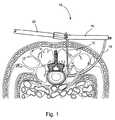
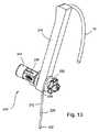
図1を参照すると、一実施形態の弓形カニューレアセンブリ10が示されている。アセンブリ10は、標的ポスト12、ガイドアーム14、及び湾曲貫通ガイド部材16を備える。器具支持アーム20は、アセンブリを保持し、手術台(図示しない)に接続されている。アセンブリ10は、段階的に連ねられた湾曲カニューレ(図1には示さない)を更に備える。その湾曲カニューレは、脊椎の目的部位へのアクセスを形成するためにガイド部材16に引き続いて導入される。弓形カニュ−レアセンブリ10を使用して、前側方アプローチから椎間板腔、又は弓形経路を通じて前方脊柱の任意の要素への進入口が形成される。進入口は、種々の椎間手術を完了するために、手術器具、インプラント、及び他の部材が通過するスムーズな通路である。この弓形後側方アプローチは、多数の手術を行うのに効果的である。それらの手術は限定されるわけではないが、以下のものを含む。可動性維持デバイスのインプラント、椎間板置換術、椎体間デバイスのインプラント、椎間板切除術、動的要素を備えた又は備えない側面プレーティング、プレート又はステープルを用いた椎骨固定或いは移植片圧縮、椎間孔拡大術、減圧、輪状切除、髄核摘出、環帯又は神経核修復、椎体生検、椎体形成術、圧潰した椎体の高さ回復(椎体拡大)、安定化特性を備えた固定ケージの移植、終板を共に保持するための歯を備えた固定ケージの移植、或いは、ケージ上に圧縮及びケージの安定を提供するために椎間板腔を横切る湾曲又は直線状のステープルの移植である。 Referring to FIG. 1, an
図2を参照すると、標的ポスト12の斜視図が示されている。標的ポスト12は、先端32及び基端34を備える長尺シャフト30を備える。基端34は、第1の側面42及び第2の側面43を有する四角状のコネクタブロック38に接続されている。コネクタブロック38の第1の側面42に接続されているのは、支持アーム取付ポスト44である。取付ポスト44は、受容スロット46を有する。受容スロット46は、境界面45を通って取付ポストの中を横切って延びている。好適な実施形態において、受容スロット46は、内部にねじ面を含む。放射状スプライン48は、境界面45上で受容スロット46を取り囲んでいる。コネクタブロック38の第2の側面43に接続されているのは、回転ポスト50である。回転ポスト50から先端に延びているのは、オプションの停止機構52である。別の実施形態は、支持アーム20及び/又はガイドアーム14が標的ポストに対してある角度で配向可能とする多軸ジョイントを備える標的ポストを含んでもよい。 Referring to FIG. 2, a perspective view of the
図3を参照すると、支持アーム20の斜視図が示されている。支持アーム20は、シャフト60を備える。シャフト60は、保持される器具の位置に適合すべく多数の自由度を許容するように、各種の連結、軸、接続を介して手術台に取り付けられている。多種多様に異なって構成された器具の支持アームがこの分野で公知であり、アセンブリ10は、外科医が選択した器具の支持アームと互換性がある。シャフト60の先端61は、第1の側面62及び第2の側面63を有する。第1の側面62から第2の側面63まで先端61を通じて横切って延びるのは、ねじ溝66である。第1の側面62において、境界面65は、ねじ溝66の開口を取り囲む放射状スプライン64を有する。放射状スプライン64は、標的ポストが支持アーム20に接続されるとき、標的ポスト12上の放射状スプライン64と係合するように構成されている。溝66を通って延びているのは親ねじ68であり、シャフト70は第2の側面63上の溝66から突出している。好適な実施形態において、シャフト70は、標的ポスト12上のねじを切られた受容スロット46と調和するように構成された外部にねじを切られた面を含む。 Referring to FIG. 3, a perspective view of the
図4に示すように、標的ポスト12は、後側方アプローチによって、患者の背中の後ろにある小さな切り口を通じて目的の脊椎部位まで患者の体内へ導入される。標的ポスト12の先端32は、チップ36が椎間板の前側方の半分又は3分の1における所望の基準位置に達するまで、患者のちょうど側方を通じて目的の椎間板まで前方内側へ進められる。ポスト12が進められるのに伴い、チップ36の鈍い形状が、組織を脇へやさしく押しのける。また、ポスト12が組織を通って進入する際に神経を回避するために、神経の監視又は筋電図検査(EMG)を許容するように、ポスト12は挿入中に電極として配線されてもよい。特別な関心事は、脊椎に隣接する腰筋がポスト12によって貫通される際、脊柱から延びる神経根を回避することである。処置されるべき椎間のレベルに関して、標的ポスト12が下側の椎体の上側の端板と同一平面上となるように、標的ポスト12は挿入される。好ましくは、ポスト12は、患者の矢状面と平行に配置されるが、神経又は他の障害物を回避するために必要であれば他の配向も可能である。標的ポスト12は、異なる体型の患者に適合するとともに、特定の基準位置へ到達するように各種の長さで利用可能である。 As shown in FIG. 4, the
標的ポスト12の先端32が基準位置に到達するとき、基端30は親ねじ68を介して支持アーム20に取り付けられる。突出ねじシャフト70は、受容スロット46内にねじ込まれる。親ねじ68がねじ込まれるとき、放射状スプライン44,64が歯合して、標的ポスト12を支持アーム20に固定する。一旦、標的ポスト12と支持アーム20との間で取り付けが行われる場合、十分に強固な器具の安定性を提供するために、支持アーム20の各種の自由度が無くなりロックされる。脊椎に隣接する位置において、標的ポスト12は、後続のカニューレ、器具、及びインプラントにとって安定化及び基準ガイドとして機能する。標的ポスト12は、更なる安定性を提供するために、患者に対して任意に固定されてもよい。 When the
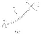
図5を参照すると、貫通ガイド部材16が示されている。ガイド部材16は、湾曲しており、弓形であってもよい(即ち、一定の曲率半径に沿って延びてもよい)。ガイド部材16は、基端110、及び挿入チップ113を備える先端112を有する。挿入チップ113は、筋肉及び筋膜を貫通するように、丸みを帯びてもよいし、或いは尖っていてもよい。基端における2つの取付凹部114は、ガイド部材16をガイドアーム14に取り付けることを容易とし、また器具支持アームに接続されるように構成されている。狭い溝が、任意にガイド部材16の長さにわたって延びてもよい。その溝は、拡張中の神経の監視又はEMG用の配線を収容するサイズである。 Referring to FIG. 5, a
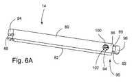
図6Aを参照すると、ガイドアーム14の斜視図が示されている。ガイドアーム14は、第1の側面80及び第2の側面82を有する。基端にあるのはピン止め端部84であり、係止端部86が反対の先端に位置する。ピン止め端部84は、取付機構88を有する。取付機構88は、標的ポスト12上の回転ポスト50に対して回転可能に取り付けるような形状に形成されている。係止端部86内の水平スロット89の中に挿入されているのは、貫通ガイド部材16を把持するように形成されたばね搭載ガイド部材係止アセンブリ90である。ガイド部材係止アセンブリ90は、鍵穴94及びタブ96を備えるスライド係止バー92を有する。ガイドアーム14の第1の側面80において、係止端部86付近にあるのは、円形ガイド部材孔100である。それと正反対の第2の側面82には、より小さいピンホール孔102が任意に存在してもよい。 Referring to FIG. 6A, a perspective view of the
図6Bは、スライド係止バー92の拡大図である。鍵穴94は、タブ96に向かって設けられた円形部95、及びタブ96と反対の卵形部97を有する。円形部95は、ガイド部材16(図示しない)の基端110の周りに適合するサイズに形成されている。卵形部97は、ガイド部材16の取付凹部114を保持するサイズに形成されている。タブ96は、水平スロット89内でスライド係止バー92を移動させるべく把持されてもよい。ばね(図示しない)は、スライド係止バー92に対する抵抗を提供するために、水平スロット89内に設けられている。 FIG. 6B is an enlarged view of the
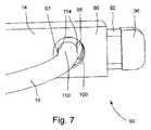
図7は、ガイドアーム14の係止端部86の拡大図であり、係止アセンブリ90内に係止されたガイド部材16を示す。ガイド部材16を係止アセンブリ90内に係止するために、まず、鍵穴94の円形部95がガイド部材孔100と一列に並ぶまで、スライド係止バー92が水平スロット89内に導入される。取付凹部114が一列に並んだ鍵穴94及び孔100と隣接するまで、ガイド部材16の基端110は挿入される。スライド係止バー92が解放され、鍵穴94の卵形部97がガイド部材16の取付凹部114の周辺にスライドするまで、ばね(図示しない)がスライド係止バー92を先端に向かって押圧する。ガイド部材が卵形部97とガイド部材孔100に隣接するガイドバー14の係止端部86との間でピン止めされとき、ばねの力がガイド部材16を係止アセンブリ90内に捕らえる。 FIG. 7 is an enlarged view of the locking
図8を参照すると、ガイドアーム14及び貫通ガイド部材16が第1の位置にある状態で、支持アーム20、標的ポスト12、ガイドアーム14、及び貫通ガイド部材16が示されている。ガイドアーム14上の取付機構88は、標的ポスト12上の回転ポスト50と係合する。従って、取り付けられ、ガイドアーム14は、回転ポスト50の軸の周りで回転可能であるが、回転ポスト50上の停止機構52は、ガイドアーム14が回転ポスト50の周りで全体的に回転することを妨げる。貫通ガイド部材16の円弧中心点が、回転中心、即ち回転ポスト50の軸と一致するように、ガイドアーム14は、貫通ガイド部材16の湾曲の半径と一致するサイズに形成されている。ガイド部材係止90は、図7に示されるように貫通ガイド部材16を保持する。貫通ガイド部材16がガイドアーム14に取り付けられた後、ガイドアーム14は回転されるため、ガイド部材16の挿入チップ113は皮膚と接触する。或いは、切開位置が皮膚にマークされてもよい。この時点で、ガイド部材16が持ち上げられて、約1〜5cmの開口が皮膚及び筋膜内に形成される。開口の後、外科医は、柔らかい組織及び筋膜を位置特定して触診するために指を開口の中に挿入する。 Referring to FIG. 8, the
その後、図9に示すように、ガイド部材16は、ガイドアーム14の回転を通じて開口の中へ進められる。挿入チップ113が目的位置にある目的の椎間板の側方マージンに達するまで、ガイド部材は弓形経路に沿って前方内側へ進められる。目的位置は、標的ポスト12の先端32によって提供される基準位置に対して既知の位置にあり、ガイドバー14が回転ポスト50の周りで回転するように、ガイドバー14が固定した関係にあるガイド部材16を保持する。この時点で、ガイドアーム及びガイド部材は第2の位置にある。ガイド部材16は、丸みを帯びた挿入チップを有してもよいし、或いは組織を貫通する必要がある場合には、鋭利な鋭い挿入チップを有してもよい。筋膜を通るガイド部材の安全な通路を確保するために、EMG監視が使用されてもよい。神経監視のために電極をガイド部材16へ接続することが望まれる場合、オプションのピンホール孔102は、ガイドアームを通ってガード部材16内へ通過する配線用のアクセスを形成する。停止機構52(図2に示す)は、ガイドアーム14の回転を停止し、ガイド部材16が椎間板のマージンを通過して延びて、脊髄に接触することを防止する。異なる患者の体型及び異なる特定の目的部位に適合するために、貫通ガイド部材16は、長さ及び曲率半径において変更可能である。従って、ガイド部材が目的位置に正確に到達すべく機能するように、ガイドアーム14は、長さにおいて調節可能であってもよい。 Thereafter, as shown in FIG. 9, the
一旦、ガイド部材16が目的位置の付近に正確に配置されるとき、ガイドアーム14はガイド部材16及び標的ポスト12から取り外される。ガイド部材16は、1つのカニューレ又は一連のカニューレ用の案内として機能するように、患者の体内に残される。一連のカニューレは、段階的なサイズであり、処置されるべき領域へのアクセスポータルの断面積を増大させるべく、より小さいものからより大きいものに順に挿入される。 Once the
図10には、単一のカニューレ18が示されている。このカニューレ18は、長手方向において湾曲するとともに、略環状に形成されており、開口先端122及び開口基端124を有する環状支持壁128を備えている。先端122は丸みを帯びており、これにより、そのカニューレが患者に挿入される際に組織をやさしくわきに押すことができる。穴130は、カニューレ18の長手方向に沿って開口先端122から開口基端124にまで延びており、器具の挿入、椎間装置、関節鏡視装置、インプラント、骨移植材料、骨セメント、及び他の材料、装置の挿入及び除去のために、対象とされた椎骨領域へアクセスすることができる。穴130の支持壁128の断面形状は、全体的に湾曲しており、具体的には、円形、卵形、楕円形又は他の湾曲形状に形成されることが可能である。その断面形状は幅132を有し、この幅132は、最大27ミリメートルになり得る。開口基端124は、外科医がカニューレを把持することを許容する複数の把持構成126を備えている。カニューレ18は、同カニューレを器具支持アームに接着可能な接着構成を備えてもよい。カニューレ18は、実質的に放射線透過性を有するものであってもよく、生体適合性ポリマー、エラストマー、セラミック、アルミニウム又は他の材料を含んでもよい。カニューレ18の長手方向における湾曲は弓形であってもよく、開口基端124と先端122とが実質的に互いに垂直するように、略90°湾曲していてもよい。カニューレの湾曲半径は、同カニューレの全体において定数であってもよく、およそ5.08cm(2インチ)からおよそ22.86cm(9インチ)までの範囲内に設定されてもよい。 In FIG. 10, a
図11に示されるように、段階的に配列された一連のカニューレ15,17,18は、貫通ガイド部材16の基端110に嵌められ、更に前内側方向においてガイド部材16の先端112にこれに対応するカニューレの先端が到達するまで、ガイド部材16に嵌められる。カニューレ17,18は、何れもその長さが最も小さいカニューレよりも短く、その断面積が最も小さいカニューレよりも大きく、これにより、これらカニューレの取付け時又は取外し時に、外科医が各カニューレを把持することができる。各カニューレ15,17,18が嵌められる際に、柔らかい組織及び筋膜におけるアクセス門脈の大きさが増大し、椎骨の対象部分への通路を増大させる。挿入されるカニューレの数は、所望の椎骨への開口面積によって決められる。多くの場合は、2つから5つのカニューレが挿入される。全てのカニューレ15,17,18が一旦貫通ガイド部材16の周りに嵌められると、ガイド部材16及び内側のカニューレ15,17が取外され、最も大きいカニューレ18が患者内に残される。このカニューレは、接着構成(図示しない)を介して支持アーム20に接着されてもよく、これにより、相対的に小さなカニューレの取外し時、その後の器具の挿入時及び処置持に、付加的な安定性を提供する。 As shown in FIG. 11, a series of
本発明の一実施形態において、最も大きいカニューレ18は、その挿入端122から長手方向に沿って延びる歯状部(図示しない)を備えてもよい。挿入の間に、この歯状部は、椎間腔の上方端板と下方端板との間に位置することにより、伸延及びその空間へのアクセスの維持を補助する。一代替実施形態として、最も大きいカニューレ18は、挿入端122から突出している1つ又は2つ以上のピン又は他の部材を備えてもよく、このような部材は、上方及び下方の椎骨体部の少なくとも一方を貫通することにより、カニューレ18に対して付加的な安定性を提供する。 In one embodiment of the present invention, the
図12は、上述した処置に基づいてカニューレが挿入された椎骨の一部を示す後側面図である。患者内の位置において、カニューレ18の穴130は、アクセス門脈であり、外科器具、インプラント又は他の材料を同アクセス門脈を通過させ、様々な椎間処置を実行することができる。カニューレ18とともに使用される外科器具は、剛性の湾曲シャフト或いは可撓性のあるシャフトを備え、カニューレ18を通って椎間腔に到達する。カニューレ18の大きさは、椎間固定インプランド或いは他のインプラント(図12では図示しない)の通過に合わせて設定されてもよい。 FIG. 12 is a posterior side view showing a portion of a vertebra with a cannula inserted based on the procedure described above. At a location within the patient, the
本発明の別の実施形態としては、頭尾が調整可能なポストを備えている。図13は、調整可能なポスト212、ガイドアーム214及び貫通ガイド部材16を含む弓形カニューレアセンブリ210の斜視図である。調整可能なポスト212は、先端232及び基端234を有するシャフト230を備えている。シャフト230の基端234は、連結部240が隣接しており、この連結部240は、頭尾方向に延びており、ガイドアームコネクタ250、頭尾調整機構238、及び支持アーム接着ポスト244を備えている。頭尾調整機構238を調整することにより、連結部240の頭尾長さを増大又は縮小することができる。そのため、ポストが患者内に挿入された後、連結部240の長さを必要に応じて調整して必要なオフセットを実行することにより、ガイド部材16とポスト212との間の最終頭尾長さを調整することができる。この調整は、対象位置の既知値がその位置に対してオフセットされるように、対象位置が頭尾方向に沿って変化することを許容する。ガイドアーム214及び接着ガイド部材16の頭尾方向におけるオフセットは、拡張過程において神経組織及び他の物体を回避するために役に立つ。 Another embodiment of the present invention includes a post with adjustable head and tail. FIG. 13 is a perspective view of arcuate cannula assembly 210 including
本発明の別の実施形態は、両側に2つの弓形のカニューレアセンブリが設置された装置を備えている。この実施形態において、2つのアセンブリ10が一緒に使用され、これらアセンブリ10は、椎骨の両側にそれぞれ配置されている。図14に示されるように、2つのポスト12、2つの貫通ガイド部材16、及び2つのカニューレ18を含む2つのアセンブリ10の各部分は、椎骨の両側にそれぞれ近接している。本実施形態により、対象領域へのアクセスが両側の双方から同時に実行されることが可能であるため、対象領域へのアクセス性を向上させることができる。器具、インプラント又は他の材料は、押される又は引かれることにより、椎間腔に進入し、或いはアクセス経路の全体を通過することができる。 Another embodiment of the present invention comprises a device with two arcuate cannula assemblies installed on both sides. In this embodiment, two
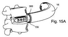
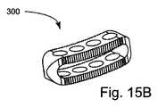
本実施形態の別の実施形態は、インプラントを更に備えており、このインプラントは、椎間装置であってもよい。図15は、第1及び第2椎骨、並びにカニューレ18及び上述した弓形のカニューレアセンブリを通じて挿入可能な椎間装置300の前方斜視図である。湾曲シャフト(図示しない)を有するインプラント保持インサータは、カニューレの弓形経路に沿ってインプラントを移動させ、このインプラントを椎骨の間の椎間空間に投下することができる。図15Bは、図15Aにおける椎間装置300の斜視図である。この椎間装置300は、全体的に長方形の箱のような形を有し、その長手方向の軸線に沿ってわずかに湾曲している。この椎間装置300は、カニューレ18の湾曲半径と実質的に同様の湾曲半径を有してもよい。 Another embodiment of this embodiment further comprises an implant, which may be an intervertebral device. FIG. 15 is an anterior perspective view of the
他のインプラント(図示しない)は、前述したような様式、即ち図15Aに示されている様式のカニューレを通じて移植可能な形に形成されてもよい。これらインプラントは、神経核代用品、体環代用品、ステープル、側板、側板と椎間インプラントとを組み合わせた装置、人工椎間板、治療作用を含むインプラント、椎骨体ねじ、椎骨体アンカー、及び関節面代用品を備えている。なお、インプラントは、これらに限らない。 Other implants (not shown) may be formed in an implantable manner through the cannula in the manner described above, ie, as shown in FIG. 15A. These implants are: nucleus substitutes, body ring substitutes, staples, side plates, devices combining side plates and intervertebral implants, artificial discs, implants with therapeutic effects, vertebral body screws, vertebral body anchors, and joint surface margins It has equipment. In addition, an implant is not restricted to these.
どのような場合でも、カニューレ18の穴130は、椎間装置300の通過に適合した大きさに設定される。椎間装置300の使用により、椎間腔へのアクセス性を向上することができるため、椎間装置300は多数の他の椎間装置よりも大きい設置面積を有することができ、椎間腔の中央から側面までの幅の大部分にわたって延びることにより、安定性の促進、骨の内部成長の促進、及び固定性の向上を図ることができる。椎間装置300を椎間腔に挿入して固定するために、湾曲挿入装置及び湾曲タンプが使用される。可撓性のある挿入装置及び/又は可撓性のあるタンプを使用してもよい。 In any case, the
上述した弓形カニューレアセンブリセットに一組の湾曲椎骨整形外科器具を併せて使用して椎骨処置を完成させることができる。これらの器具は、以下の明細書及び図17〜27において説明される。これらの器具は、やすり、キュレット、骨鉗子、楔形ディストラクタ、試用移植物、タンプ、探針及び移植物挿入装置等を備えてもよい。各器具は、把持部と、シャフト、及び特定の作用部或いは作業端を有する作業部とを備えてもよい。そのシャフトは、弓形シャフト経路に沿って延びる弓形シャフトであってもよく、その弓形シャフト経路は、弓形シャフトに対応するカニューレの延びる方向に沿った経路に適合する。各器具の作業端部は、弓形カニューレ18を通過できる大きさに設定され、同作業端部が弓形シャフトと同じ軌跡に沿って移動するようにその弓形シャフトに固定されてもよい。このように、作業部の全体は、弓形シャフト通路に沿って連続的に湾曲することができる。弓形シャフト通路の曲率半径は、実質的に弓形カニューレ18の曲率半径と同じ値に設定されてもよい。このような構成により、各器具の作業部は、弓形カニューレに挿入され、その作業端がカニューレの先端から突出して椎骨処置の位置に到達することを許容する。 The arcuate cannula assembly set described above can be used in conjunction with a set of curved vertebral orthopedic instruments to complete the vertebral procedure. These instruments are described in the following specification and FIGS. These instruments may include files, curettes, bone forceps, wedge-shaped distractors, trial implants, tamps, probes, implant insertion devices, and the like. Each instrument may include a gripping part, a shaft, and a working part having a specific working part or working end. The shaft may be an arcuate shaft extending along an arcuate shaft path, the arcuate shaft path being adapted to a path along the direction of extension of the cannula corresponding to the arcuate shaft. The working end of each instrument may be sized to pass through the
図16は、カニューレ18の斜視図である。このカニューレ18は、湾曲しており、図16において具体化されたように、弓形である。このように、カニューレ18は、器具が通過可能な弓形空間を区画している。このカニューレ18(従って、弓形空間)は、弓形空間経路136に沿って縦に延びており、およそ5.08cm(2インチ)からおよそ30.48cm(12インチ)までの範囲内にある半径を有している。より正確には、弓形空間通路は、およそ10.16cm(4インチ)からおよそ22.86cm(9インチ)までの範囲内にある半径を有している。更に正確には、弓形空間通路は、およそ13.97cm(5.5インチ)の半径を有してもよい。カニューレを構成した支持壁128は、内側面134を備えている。上述したように、この内側面134は、弓形空間を区画している。弓形空間、従ってカニューレ18は、弓形空間経路136に沿って縦に延びており、およそ45°からおよそ135°までの範囲内にある角度の弧形に沿って湾曲してもよい。より正確には、カニューレ18は、およそ60°からおよそ120°までの範囲にある弧形に沿って湾曲してもよい。更に正確には、カニューレ18は、およそ75°からおよそ105°までの範囲内にある角度の弧形に沿って湾曲してもよい。更に正確には、カニューレ18は、およそ90°の弧形に沿って湾曲してもよい。 FIG. 16 is a perspective view of the
カニューレ18(従って、これに対応する空間)は、実質的に一定の断面形状を有し、その断面形状は、円形、卵形、楕円形、又は他の一定な、且つ閉じられた形状であってもよい。「実質的に一定の断面形状」は、押出成形、即ち長手方向に沿って任意の位置において実質的に同じ断面形状及び大きさを有する通路に沿って延びる本体の形状である。弓形空間の最大幅、即ち弓形空間通路136に対して垂直な方向に沿った断面の最大径を横切る直線の長さは、およそ5mmから50mmまでの範囲内にあってもよい。より正確には、その最大幅は、およそ15mmから40mmまでの範囲内にあってもよい。更に正確には、その最大幅は、およそ20mmから30mmまでの範囲内にあってもよい。更に正確には、その弓形空間の最大幅は、およそ27mmであってもよい。弓形シャフト及び各器具の作業端は、弓形空間を通過可能に、且つその作業端が空間から延出可能に形成されて一体に連結されている。 The cannula 18 (and thus the corresponding space) has a substantially constant cross-sectional shape, which is circular, oval, elliptical, or other constant and closed shape. May be. A “substantially constant cross-sectional shape” is the shape of a body that extends through an extrusion, that is, a passage having substantially the same cross-sectional shape and size at any location along the longitudinal direction. The maximum width of the arcuate space, i.e., the length of the straight line across the maximum diameter of the cross section along the direction perpendicular to the arcuate space passage 136, may be in the range of approximately 5 mm to 50 mm. More precisely, the maximum width may be in the range of approximately 15 mm to 40 mm. More precisely, the maximum width may be in the range of approximately 20 mm to 30 mm. More precisely, the maximum width of the arcuate space may be approximately 27 mm. The arcuate shaft and the working end of each instrument are integrally connected so as to be able to pass through the arcuate space and extend from the space.
図17において、湾曲シャフトを有する器具は、弓形カニューレアセンブリ10の弓形カニューレ18を通じて挿入されて椎骨処置の位置に到達する。1つの椎骨が示されることにより遠近感を提供しており、第2の椎骨が省略されることによりその器具の作業端が見えるようになる。楔形ディストラクタ750は、以下に説明する楔形ディストラクタ700と似ているが、その楔ヘッドが相違し、カニューレ18を通じて挿入されて椎間腔に到達する。楔形ディストラクタ750の作業部は、作業端(ここでは楔ヘッド)、及び作業ヘッドをハンドルに固定するシャフトを備えている。この弓形シャフトは、湾曲してもよく、更に、弓形カニューレ18の内側面によって区画された弓形空間を通過可能な弓形シャフトを提供するために一定の半径で湾曲してもよい。 In FIG. 17, an instrument having a curved shaft is inserted through the
図18は、湾曲骨鉗子400の斜視図である。この骨鉗子400は、把持部402及びこれに近接するレバー408と、湾曲シャフト404及び作業端としての挟持機構406とを備えている。把持部402は、弓形シャフト通路に沿って延びる湾曲シャフト404の基端に連結されている。弓形シャフト404の先端は、挟持機構406に連結されている。弓形シャフト404は、縦に設けられた2つの弓形要素、即ち柄410及び横木412を備えている。柄410は、把持部から停止部416まで延びている。横木412は、連結材405によってレバー408に連結されている。ピボット418は、レバー408が駆動される際に同レバー408がピボット418の回りに回転するとともに、連結された横木412が柄410に沿ってスライドするように、レバー408を把持部402に連結している。挟持機構406は、横木412の先端414及び停止部416を含んでいる。レバー408が完全に駆動された場合には、横木412は、横木412の先端414が停止部416に当接するまで、柄410に沿ってスライドする。 FIG. 18 is a perspective view of the
外科処置の際に、湾曲骨鉗子400は、図16における弓形カニューレ18のような弓形カニューレを通じて挿入されてもよく、挟持機構406は、把持部402及びレバー408の操作により、骨、軟骨、椎間板組織、又は他の組織及び材料を掴んで移動させることができる。湾曲シャフト404は、挟持機構406が例えば2つの椎骨の間における椎間腔等の対象領域における複数の位置に到達できるように、十分に細く、且つ長く形成されている。 During the surgical procedure, the
図19は、湾曲キュレット500の一実施形態を示す斜視図である。この湾曲キュレット500は、把持部502を備えており、この把持部502には、弓形シャフト経路512に沿って延びる弓形シャフト504が連結されている。弓形シャフト経路512は、およそ5.08cm(2インチ)からおよそ30.48cm(12インチ)までの範囲内にある半径を有してもよい。より正確には、弓形シャフト経路512は、およそ10.16cm(4インチ)からおよそ22.86cm(9インチ)までの範囲内にある半径を有してもよい。更に正確には、弓形シャフト経路512は、およそ13.97cm(5.5インチ)半径を有してもよい。弓形シャフト経路512の曲率は、弓形空間通路136の曲率に合うように設定されてもよい。これらの寸法は、本件に開示される任意の器具又はカニューレに適合されてもよい。 FIG. 19 is a perspective view showing an embodiment of the
弓形シャフト504の先端は、切削ヘッド506である作業端に連結されている。切削ヘッド506は、スプーン形であり、杯状部の縁を形成しているコップ508及びブレード510を備えている。切削ヘッド506を弓形シャフト504に対して複数の方位及び角度に設定することができる。図19において、切削ヘッド506は、弓形シャフト504の湾曲に協調されており、キュレット500が図示されるように水平に保持される際に、コップ508が上方に開放する。 The tip of the
図20A〜20Cは、切削ヘッドが椎間腔における様々な領域に到達することを許容する他の方位態様を示している。各方位態様は、切削ヘッドが弓形カニューレを通過することを許容している。切削ヘッドは、これが斜めな向きに設置されたとしても、カニューレ18によって区画された弓形空間に適合できるように、十分に小さく形成されてもよい。図20Aにおいて、切削ヘッド506は、弓形シャフト504に対して上方に開放するとともに、そのシャフトの軸線に対して斜めに配置されている。図20Bにおいて、切削ヘッド506は、弓形シャフト504と一直線に配置されるとともに、下方に開放している。図20Cにおいて、切削ヘッド506は、下方に開放するとともに、弓形シャフト504に対して斜めに配置されているが、カニューレ18の内側面によって区画された弓形空間に適合することができる。この方位態様の多様性により、外科医は、手元においてこの特殊な職業のために最適なキュレット形状を選択することができる。 20A-20C illustrate other orientation aspects that allow the cutting head to reach various regions in the intervertebral space. Each orientation aspect allows the cutting head to pass through the arcuate cannula. The cutting head may be made small enough so that it can fit into the arcuate space defined by the
図21は、湾曲やすり600の一実施形態を示す斜視図である。この湾曲楔形やすり600は、把持部602と、弓形シャフト604、及びやすりヘッド606となる作業端とを備えている。やすりヘッド606は、弓形シャフト604の先端に連結されている。弓形シャフト604は、湾曲キュレット500の弓形シャフト経路512と同様の弓形シャフト経路に沿って湾曲している。弓形シャフト604及びやすりヘッド606により作業部が構成され、この作業部は、例えば、図17に示されるような上述の方法におけるカニューレ18等の弓形カニューレを通過することに適合する大きさ及び向きに形成されている。やすりヘッド606は、全体的に方形に形成されているが、弓形空間経路136(図16に示される)に沿って僅かに湾曲している。このような楔は、湾曲シャフトとの組合せにおいて従来の平坦なやすりヘッド606を有してもよい。 FIG. 21 is a perspective view showing an embodiment of the
第1歯状やすり表面608は、やすりヘッド606の1つの長い側面を占めるとともに、第2歯状やすり表面610は、その反対側に位置している。楔612はヘッド606の先端に位置しており、外科医は、対象領域を詮索して伸延し、そして伸延された表面にやすりをかける。このやすりヘッドの複数の寸法を変更してもよい。これらの寸法は、やすりヘッド606の長さ、高さ及び幅、やすり歯の寸法、楔612の長さ等を含む。やすりヘッドの高さは、インプラントの高さに適合する寸法に設定されてもよく、これにより、その楔は、インプラントを挿入するための適切な寸法を有する領域を提供することができる。安定化構成614は、弓形シャフト604の広幅の部分であり、弓形カニューレ18の内に嵌入されることにより、作用力がハンドル602に加わる際にやすり600の位置を安定させる。把持部602は、その基端に設けられた強化固着表面616を備え、この表面により、例えば槌等を用いて行う打撃を容易にすることができる。 The first
図22は、湾曲楔ディストラクタ700を示す斜視図である。この湾曲楔ディストラクタ700は、把持部702と、弓形シャフト704と、楔ヘッド706となる作業端とを備えている。この楔ヘッド706は、弓形シャフト704の先端に固定されている。弓形シャフト704は、湾曲キュレット500の弓形シャフト経路512と同様の弓形シャフト経路に沿って湾曲している。把持部702の基端には、固着表面708が形成されている。伸延処置の間に、槌又は他の打撃器具を用いて湾曲楔ディストラクタ700に力を作用させることができる。この固着表面708は、ダメージに耐えるように強化された領域であり、力を楔ヘッド706に向かって伝達する。その楔ヘッド706は、楔形の尖端部710、及び広幅の方形ブロック部710を備えている。この楔ディストラクタ700に作用力が加わった際に、相対的に小さな先端部710はまず椎間腔に進入し、この椎間腔を楔で徐々に伸延する。これと一緒に進むブロック部710は、この伸延を保持する。安定化構成714は、弓形シャフト704の広幅の部分であり、弓形カニューレ18(図示しない)の内に嵌入されている。この安定化構成714は、楔ヘッド706が精密に区画された経路を通じて椎間腔に進入することを許容し、固着表面708に力が作用される際に、ディストラクタ700の全体位置を安定化させる。 FIG. 22 is a perspective view showing a
楔ヘッド706を複数の態様に配置できることは好まれている。例えば、図17における楔ディストラクタ750は、ブロック部を有しない楔ヘッドを備えている。この楔ヘッドにおいて、楔の角度、楔部の幅又は長さ、ブロック部の幅、高さ又は長さ、ブロック部に対する楔部の比率、片の数等を変更してもよい。段階的な大きさの楔ヘッドを有する一連の楔ディストラクタは、椎間腔を連続的に伸延することができる。1つの処置のために選択された楔ディストラクタヘッドの高さは、同じ処置において用いられるインプラントの高さに適合してもよい。 It is preferred that the
図23は、試験用インプラント用器具800の斜視図である。試験用インプラント用器具800は、把持部802及び作業部を有する。作業部は、弓形シャフト804と作業端を有する。弓形シャフト804は、湾曲キュレット500の弓形シャフト通路512と同様の弓形シャフトに沿って延びている。把持部802の基端には、埋伏面808がある。埋伏面808は、マレットやその他の打ち付け器具の力に耐えられるよう補強されている。弓形シャフト804の先端末には、作業端としての試験用インプラント806が位置する。試験用インプラント806は、弓形シャフト804と同様の軌道に沿って湾曲する。試験用インプラント806は、シャフト804の先端に取り外し不能に連結されてもよい。または、着脱可能に連結されてもよく、この場合、他の試験用インプラントに変更可能である。機能、形状及び/又は大きさの異なる複数種の試験用インプラント(試験用インプラント806が弓形シャフト804から取り外し不能である場合は、複数種の試験用インプラント器具)を使用することが可能である。これにより、使用者は、複数の試験用インプラントを挿入及び取り外しをして最終的に選択すべきインプラントを決定する。 FIG. 23 is a perspective view of a
図24は、インプラント挿入器900の斜視図である。インプラント挿入器900は、把持部902と弓形シャフト904とを有する。弓形シャフト904は、湾曲キュレット500の弓形シャフト通路512と同様の弓形シャフトに沿う。弓形シャフト904の先端には、作業端としてのインプラントコネクタ906が位置する。弓形シャフト904は、インプラント保持機構910を備えている。インプラント保持機構910は、把持部に設けることもできる。インプラント保持機構910は、弓形シャフト904を介してインプラントコネクタ906に接続されており、図15A及び図15Bの椎間インプラント300等の脊椎インプラントを保持及び保持解除することが可能である。インプラント保持機構910は、カニューレ18などの弓形カニューレにより画定される弓形空間に収まるようなサイズに形成されている。マレットやその他の打ち付け器具の力に耐えられるよう補強されている埋伏面808を把持部902の基端に設けてもよい。 FIG. 24 is a perspective view of the
図25は、可撓シャフトを有する可撓インプラント挿入器を示す。可撓インプラント挿入器950は、把持部952と可撓シャフト954とを有する。可撓シャフト954は、図25に示すよう直立姿勢であってもよく、湾曲姿勢になるよう曲げられてもよい。可撓シャフト954の先端には、作業端としてのインプラントコネクタ956が位置する。インプラント挿入器900と同様、可撓インプラント挿入器950は、インプラントコネクタ906に連結されたインプラント保持機構960を有する。図15A及び図15Bの椎間インプラント300等の脊椎インプラントは、インプラントコネクタ956に連結されてもよい。インプラント300及び可撓シャフト954は、図16のカニューレ18に挿入される。可撓シャフト954がカニューレ18に挿入されるとき、可撓シャフト954は、カニューレ18の曲率、つまり弓形内部通路136の曲率に応じて曲げられる。インプラント300が椎間の空間に位置した後、インプラント保持機構910の作動によりインプラント300が解放されて、可撓インプラント挿入器950がカニューレ18から抜き出される。 FIG. 25 shows a flexible implant inserter having a flexible shaft. The
図26は、湾曲ゾンデ1000の斜視図である。湾曲ゾンデ1000は、把持部1002と弓形シャフト1004とを有する。弓形シャフト1004は、湾曲キュレット500の弓形シャフト通路512と同様の弓形シャフトに沿う。作業端としてのゾンデ先端1006が弓形シャフト1004の先端から直角に延びている。弓形シャフト1004及びゾンデ先端1006は、脊椎外科手術において脊椎の手術部位を探査及び試験するために弓形カニューレ18(図示せず)に挿入され、組織の特定或いはその他の機能を実行するために用いられる。弓形カニューレアセンブリと共に用いられる場合、図26に示すゾンデ先端1006は前方に延びる。一方、ゾンデ先端1006は、弓形シャフト1004の先端から後方及び側方等のいずれの方向に延びてもよい。 FIG. 26 is a perspective view of the
図27は、湾曲タンプ1100の斜視図である。湾曲タンプ1100は、把持部1102と弓形シャフト1104とを有する。弓形シャフト1104は、湾曲キュレット500の弓形シャフト通路512と同様の弓形シャフトに沿う。弓形シャフト1104の先端には、作業端としてのタンプヘッド1106が位置する。椎間インプラント300或いは他のインプラントをインプラント挿入器900により配置した後、湾曲タンプ1100は、インプラントの位置を微調整するためカニューレ18を通じて用いられる。補強埋伏面1108は、把持部1102の基端に設けてもよい。 FIG. 27 is a perspective view of the curved tamp 1100. The curved tamp 1100 has a
上記に説明し、図17〜図27に示した各器具は、図17に示す方法で湾曲カニューレ18に挿入される。可撓インプラント挿入器950以外の各機器のシャフトは、剛体材料で弓形に形成されてもよい。或いは、各機器のシャフトは、曲げやすい材質で形成してもよい。これにより、各機器は、可撓インプラント挿入器950のように、弓形に曲げることが可能になり、弓形カニューレによって画定される弓形空間に挿通することが可能になる。このように可撓シャフトで構成された機器は、湾曲カニューレに挿入して用いることができるが、特定の曲率半径を有さない。 Each instrument described above and shown in FIGS. 17-27 is inserted into the
各機器の把持部は、図17〜図27にそれぞれ記載の向きでシャフトに接続されてもよい。或いは、各機器の把持部は、シャフトに対して所定角度をなすように接続されてもよい。詳細には、把持部は、シャフトの基端に対して直角をなすように設けられてもよい。他の実施形態として、把持部は、その長軸が作業端の長軸と平行になるように配置してもよい。このようにすると、機器の把持部での動きが、作業端での同様の動きに変換され、使用者にとって、触覚的な操作が可能になる。 The gripping part of each device may be connected to the shaft in the directions described in FIGS. Or the holding part of each apparatus may be connected so that a predetermined angle may be made with respect to a shaft. Specifically, the grip portion may be provided so as to be perpendicular to the proximal end of the shaft. As another embodiment, the grip portion may be arranged so that its long axis is parallel to the long axis of the working end. If it does in this way, the movement in the holding part of an apparatus will be converted into the same movement at a work end, and tactile operation will become possible for a user.
脊椎手術の実施に際しては、上記湾曲器具の一又は複数を弓形カニューレに挿入し、手術部位に到達させる。例えば、二つの椎骨間に椎間デバイスを移植する際、湾曲キュレット500、湾曲やすり600或いは、湾曲骨鉗子400などの第1の機器を弓形カニューレに挿入し、作業端を用いて、椎間腔及び椎体終板の準備を行う。その機器を除去した後、同じタイプの第2の準備用機器を一又は複数、挿入して使用してもよい。椎間腔及び椎体終板の準備が完了すると、試験用インプラント用器具800を用いて、様々なサイズの試験用インプラントを、カニューレを通して挿入し、適切なサイズを有する椎間インプラントを決定する。最後に、椎間インプラント300が湾曲インプラント挿入器900を用いてカニューレに挿入され、解放され椎間腔に移植される。このとき、湾曲タンプ1100を用いて移植済みインプラント300の位置を調整してもよい。 In performing a spinal surgery, one or more of the bending instruments are inserted into an arcuate cannula to reach the surgical site. For example, when implanting an intervertebral device between two vertebrae, a first instrument such as a
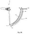
図28は、本発明の別の実施形態を示す。腹膜レトラクタ150を弓形カニューレアセンブリ10と共に用いて、カニューレ18または拡張器の経路付近の組織を牽引、保護するようにしてもよい。腹膜レトラクタ150は、湾曲した半パイプ状の形状を有し、丸みを帯びた先端152と基端154とを有する。平坦リップ156が基端154から直角に延びており、腹膜レトラクタ150を把持し案内するのに用いられる。ガイド部材16、カニューレ18、及び組織の開口の拡延を容易にする中間カニューレの湾曲に合うように、腹膜レトラクタ150は長手方向において湾曲している。湾曲ガイド面158は、基端154から先端152まで伸び、ガイド部材16及び導入されるカニューレを案内する。 FIG. 28 illustrates another embodiment of the present invention. The
腹膜レトラクタ150は、前述したような標的ポストが導入された後、患者に導入される。外科医が切開箇所をマークし切開した後、軟組織及び筋膜を特定して触診するため、指を切開箇所に挿入してもよい。次に、該組織を保護、保持するため、指に沿って、腹膜レトラクタ150をゆっくりと挿入する。レトラクタ150は、丸みを帯びた先端152が腰筋に接触するまで挿入される。ガイド部材16は、挿入端113が目標位置にある目標ディスクの外側縁に到達するまで、湾曲ガイド面158に沿った弓形経路を前内側に進む。腹膜レトラクタ150は、図11に示すカニューレ15、17、18が段階的に上記ガイド部材16に重ねられつつ挿入される間は、その場所に留まる。このとき腹膜レトラクタ150は、周囲の組織がガイド部材を覆うことを防ぎ、カニューレ15、17、18の挿入を容易にする。外科手術の完了後、最も大きなカニューレ18が除去され、そのあとレトラクタ150が除去される。 The
本発明の別の実施形態は、内視鏡などの視覚化部品を含む。図29では、内視鏡170が弓形カニューレ10とともに用いられている。内視鏡は、管172を有する。管172の先端には、開口174が設けられ、基端には、接眼部176が設けられる。ビデオ接続端子178が接眼部176の近傍に設けられる。内視鏡は、筒172を、先端に開口162を有する中空の標的ポスト160に挿入することで配置される。接眼部176を通して、或いはビデオ接続端子178を用いてディスプレー画面を通して、外科医は、対象箇所での外科手術を見ることができる。光ファイバーを含む光源を用いて対象箇所を照らしてもよい。或いは、内視鏡は可撓管を有してもよく、その場合、標的ポストである弓形カニューレに挿入される。 Another embodiment of the invention includes a visualization component such as an endoscope. In FIG. 29, an
上記の弓形後側方アプローチは脊髄手術、とくに前脊柱部位の手術において多くの利点を有する。このアプローチは、人工椎間板置換術などにおける可動性維持デバイスの挿入に使用される。弓形後側方アプローチにより椎間板腔にアクセスすることで、外科医は、大血管の合併症や前縦靱帯への影響を避けることができる。また、このアプローチを使用すれば、最初の手術と反対側の側部から椎間板腔にアクセスすることで実質的に同一の機器およびインプラント構造を使用した変更が可能になる。このアプローチによれば、前方アプローチTDR機能より望ましい、人工椎間板置換術(TDR)での終盤保持機能が可能になる。この保持機能は、腰椎の前弯性部位に作用するせん断荷重に耐えるために前額面に沿った向きに配置されている終盤の竜骨状あるいは歯状突起などで実現される。 The above arcuate posterior approach has many advantages in spinal surgery, especially in the anterior spinal region. This approach is used for the insertion of mobility maintenance devices such as in artificial disc replacement. Accessing the disc space with an arcuate posterior lateral approach allows the surgeon to avoid macrovascular complications and anterior longitudinal ligament effects. This approach also allows for changes using substantially the same equipment and implant structure by accessing the disc space from the side opposite the initial surgery. This approach allows an endplate retention function in artificial disc replacement (TDR), which is more desirable than the anterior approach TDR function. This holding function is realized by an end keel-like or dentate process or the like arranged in a direction along the frontal face in order to withstand a shear load acting on the lordosis of the lumbar vertebra.
このアプローチは、種々の椎間板治療または切除手術に適用できる。これらの治療及び手術としては、椎間板の腫れや脱出に対処するための輪状切除、髄核摘出、椎間板切除、環帯置換、神経核置換、及び減圧が含まれる。輪状切除に際しては、外科医は、上述の方法でアクセスポータルを確保し、椎間板環の一部又は全部を切開及び/又は切除することができる。髄核摘出に際し、外科医は、上述の方法でアクセスポータルを確保し、椎間板髄核を切開及び/又は切除することができる。椎間板切除に際しては、外科医は、アクセスポータルを介して椎間板の一部または全部を除去することで、神経根、硬膜、脊髄の減圧を行う。この処置は、患者の症状や疼痛を軽減する保存療法として行われてもよいし、人工椎間板置換術または固定術の準備として行われてもよい。 This approach can be applied to various disc treatments or excision procedures. These treatments and surgeries include annulotomy, nucleotomy, discectomy, ring replacement, nerve replacement, and decompression to address disc swelling and prolapse. During an annulotomy, the surgeon can secure the access portal in the manner described above and incise and / or excise part or all of the disc annulus. Upon nucleusectomy, the surgeon can secure the access portal in the manner described above to incise and / or resect the intervertebral disc nucleus. During discectomy, the surgeon performs decompression of the nerve root, dura mater, and spinal cord by removing part or all of the disc through the access portal. This procedure may be performed as a conservative therapy that reduces the patient's symptoms and pain, or may be performed in preparation for an artificial disc replacement or fusion.
環帯修復または置換においては、弓形後側方アプローチが太い針の使用を容易にするとともに、複雑な血管構造の回避を可能にする。また、人工環帯の経路を確保し、該人工環帯が椎間板腔に載置あるいは形成されやすくなる。図14にあるように弓形アプローチを両側に用いれば、シールド、ガード、モールドなどの結合要素の形成が容易になり、環帯が修復、形成、挿入、作成、または増加が可能になる。同様の効果は、種々の技術を用いて、すべてのあるいは一部の椎間板髄核を修復、切除及び置換、形成、または増加するための神経核置換で得ることができる。人工髄核は、上述の弓形後側方アプローチを用いることで、経椎弓根的(transpedicular)アプローチで得られるものより大きな経路を通って、前方アプローチよりシンプルでリスクの低い構造によって供給される。電気外科的な治療法などの種々の椎間板治療方法が提案されてきた。弓形後側方アプローチを使用した上記治療法が臨床上の成果を向上させるとともに外科医にとって有益であることは当業者には明らかである。 In annulus repair or replacement, the arcuate posterior lateral approach facilitates the use of thick needles and allows for avoidance of complex vasculature. In addition, a route for the artificial annulus is secured, and the artificial annulus becomes easy to be placed or formed in the disc space. Using an arcuate approach on both sides as in FIG. 14 facilitates the formation of coupling elements such as shields, guards, molds, etc., allowing the annulus to be repaired, formed, inserted, created, or increased. Similar effects can be obtained with neuronuclear replacement to repair, resect and replace, form, or increase all or part of the nucleus pulposus using various techniques. The artificial nucleus pulposus is delivered by a simpler, less risky structure than the anterior approach, through a larger path than that obtained with the transpedicular approach, using the arcuate posterior lateral approach described above . Various intervertebral disc treatment methods have been proposed, such as electrosurgical treatment. It will be apparent to those skilled in the art that the above treatment using an arcuate posterior approach improves clinical outcome and is beneficial to the surgeon.
弓形後側方アプローチは、椎間デバイスの挿入、側面プレーティング、前方プレーティング、動的安定化或いは圧縮要素を用いた側面或いは前方プレーティング、変形補正、および/又は移植片圧縮装置または方法などの、椎体可動部分の安定化処置に使用できる。図15Aに示すような弓形後側方アプローチのポータルは、単一の外科的露出によって、または図15Bに示すものと同様の椎体間固定装置などのすべての必要な安定要素を挿入可能な姿勢を患者にとらせることによって、あるいは柄付きねじ、ロッド、フック、ファセットねじなどの後方安定化ハードウェアを用いることによって、椎体間固定処置を容易にする。椎体に隣接する接線あるいは中央横方向の略直線状の軌道に沿って椎間板腔に接近することで、椎間デバイスが椎間板腔をさらに満たす。このことにより、次のような種々の効果が得られる。つまり、椎体の終板の皮質領域の高い強度を利用可能になり、より大きな断面積またはより大きな設置面積で安定性が増し、骨移植表面積が増すことで骨結合、骨融合、および360°融合がより強固になる。椎間デバイスの前弯角は、経椎間孔腰椎椎体間固定術(TLIF)や後方進入腰椎椎体間固定術(PLIF)の場合のように過度の伸延を必要としない角度にしてもよい。 Arched posterior lateral approaches include intervertebral device insertion, lateral plating, anterior plating, lateral or anterior plating with dynamic stabilization or compression elements, deformation correction, and / or graft compression devices or methods, etc. It can be used for the stabilization treatment of the vertebral body movable part. The arcuate posterior approach portal as shown in FIG. 15A is capable of inserting all necessary stabilizing elements, such as an interbody fusion device similar to that shown in FIG. 15B, with a single surgical exposure. The interbody fusion procedure is facilitated by allowing the patient to take or by using posterior stabilizing hardware such as a handle screw, rod, hook, facet screw or the like. The intervertebral device further fills the intervertebral disc space by approaching the intervertebral disc space along a tangential line adjacent to the vertebral body or along a substantially transverse trajectory in the central lateral direction. As a result, the following various effects can be obtained. That is, higher strength of the cortical region of the endplate of the vertebral body is available, increased stability with a larger cross-sectional area or larger footprint, and increased bone grafting surface area for osteosynthesis, bone fusion, and 360 ° Fusion becomes stronger. The anterior angle of the intervertebral device should be such that it does not require excessive distraction, as in transforaminal lumbar interbody fusion (TLIF) or posterior approach lumbar interbody fusion (PLIF). Good.
弓形後側方アプローチは側面プレーティングに用いてもよく、その場合移植されたプレートは固定、動的、又は圧縮要素を含んでも良い。このアプローチでは、患者の姿勢を変えずに、ねじ、フック、ロッドなどの後方安定化ハードウェアを用いつつ、側面プレーティングを可能にする。これらのプレートは局所的な変形矯正や局所的な側弯、後弯、脊柱前弯過度、脊椎すべり症の予防に使用することもできる。加えて、弓形後側方アプローチによると、新規な移植片圧縮装置の使用が可能になる。また、外科医が椎体と椎間デバイスの間の局所的圧力を改善することも可能になる。局所的圧縮力の改善により、椎間腔への過度な圧縮や従来の柄付きねじ、ロッドを介した意図しないモーメントの付与で椎間デバイスが押し出しの危険性が少なくなるとともに、骨移植片の取り込み、融合、椎間板デバイスの安定が図られる。このような移植片圧縮デバイスとしては圧縮機能を有する側板、上椎体及び下椎体と協働して圧力を加える椎体ステープル、及び椎体と協働してねじ、テーパー面などにより圧力を加えるアームを備えた一体型椎間デバイスが挙げられる。 An arcuate posterior approach may be used for lateral plating, in which case the implanted plate may include fixed, dynamic, or compressive elements. This approach allows lateral plating while using posterior stabilization hardware such as screws, hooks, and rods without changing the patient's posture. These plates can also be used to correct local deformation, prevent local scoliosis, kyphosis, lordosis, spondylolisthesis. In addition, the arcuate posterior approach allows the use of a novel graft compression device. It also allows the surgeon to improve the local pressure between the vertebral body and the intervertebral device. Improved local compression forces reduce the risk of extrusion of the intervertebral device due to excessive compression in the intervertebral space and the application of unintentional moments via conventional handle screws and rods, Uptake, fusion, and stability of the disc device are achieved. Such a graft compression device includes a side plate having a compression function, a vertebral body staple that applies pressure in cooperation with the upper vertebral body and the lower vertebral body, and a screw, a tapered surface, etc. in cooperation with the vertebral body. An integrated intervertebral device with an adding arm.
種々の中心管又は小孔減圧処理が上記の弓形後側方アプローチにより行われてもよい。減圧処理は神経根、硬膜、脊髄などの神経要素に影響を与え、結果として神経根障害、骨髄障害、疼痛、刺痛、無感覚、運動機能や感覚機能の喪失などの種々の病理を引き起こす可能性がある軟組織又は硬組織を切除するために行われる。例えば、罹患椎間板への対処として行われる前方中心管減圧はしばしば困難を伴う。上記の弓形後側方アプローチを用いることで、この減圧処理は患者位置決め、患者へのアクセス、患者アウトカムが完全される。弓形後側方アプローチを介した小孔減圧処理により、外科医が孔の減圧を行う軌道や通路を改善できる。 Various central tube or stoma decompression processes may be performed by the arcuate posterior side approach described above. Depressurization affects nerve elements such as nerve roots, dura mater and spinal cord, resulting in various pathologies such as nerve root disorders, bone marrow disorders, pain, stinging, numbness, loss of motor function and sensory function This is done to remove possible soft or hard tissue. For example, anterior central canal decompression performed as a treatment for an affected disc is often difficult. Using the arcuate posterior lateral approach, this decompression process is complete for patient positioning, patient access, and patient outcome. A stoma decompression process via an arcuate posterior lateral approach can improve the trajectory and path through which the surgeon decompresses the hole.
弓形後側方アプローチは、椎体の生検、椎体高さ回復処置、および椎体形成術といった椎体の処置に適している。椎体の疾病、圧潰、骨折に関連した症状を訴える患者はしばしば椎体の状態を確認するために椎体の生検を受ける。骨粗鬆症の患者、特に老婦人の患者には椎体の圧潰や骨折が見られる。非常な痛みを伴い衰弱を進めるこれらの症状は、本件に開示された弓形後側方アプローチを用いた椎体形成術によって対処可能である。椎体形成術、亀背形成術、弓形形成術の処置は経椎弓根的アプローチにより行われ、PMMAセメントなどの硬化性組成物を椎体に注入して骨片や骨折箇所を安定させるギブス状構造が内部に形成される。弓形後側方アプローチはこういった処置に適した多くの効果を有する。経椎弓根的アプローチで使用されるものより大型のアクセス針の使用が可能になり、粘性のある硬化性組成物へかける圧力を低くできる。加えて、茎に侵入することがないので術後疼痛の軽減が予想される。さらにアクセス針の軌道をより好ましいものにすることができる。経椎弓根的アプローチで行われる椎体形成術では椎体の十分な安定を確保するため両側アプローチを必要とすることが多い。弓形後側方アプローチの軌道を用いることで、外科医や放射線医が単一の針および単一のアプローチで充填を完了することが可能になる。これは充填を完了する間、アクセス針が先端まで進められ、ゆっくりと引き戻すことが可能だからである。 The arched posterior lateral approach is suitable for vertebral body procedures such as vertebral body biopsy, vertebral body height restoration procedures, and vertebroplasty. Patients complaining of symptoms related to vertebral body disease, collapse, or fracture often undergo vertebral body biopsy to confirm vertebral body condition. Patients with osteoporosis, especially elderly women, have vertebral body collapse and fractures. These very painful and debilitating symptoms can be addressed by vertebroplasty using the arcuate posterior lateral approach disclosed herein. Vertebroplasty, dorsoplasty, and archoplasty are performed using a transpedicular approach, and a curable composition such as PMMA cement is injected into the vertebral body to stabilize bone fragments and fractures. A shaped structure is formed inside. The arcuate posterior approach has many effects suitable for these procedures. Larger access needles can be used than those used in the transpedicular approach, and the pressure on the viscous curable composition can be reduced. In addition, since it does not invade the stem, postoperative pain is expected to be reduced. Furthermore, the trajectory of the access needle can be made more favorable. Vertebroplasty performed with a transpedicular approach often requires a bilateral approach to ensure sufficient vertebral stability. Using an arcuate posterior approach trajectory allows the surgeon or radiologist to complete the filling with a single needle and a single approach. This is because the access needle can be advanced to the tip and slowly pulled back while filling is complete.
椎体高さ回復処置は最近、当該分野で発表されたものであり、圧潰した椎体に対処するためのものである。経椎弓根的アプローチのようなサイズ制限がないため、弓形後側方アプローチは椎体高さ回復処置を容易にする。加えて、椎体の外側縁へのアクセスが可能なので、椎体高を復元するインプラントを挿入し硬化性組成物で所定の場所に固定する際に有効である。また、内部椎体伸延を行って硬化性組成物で椎体を固定する処置にも有効である。 Vertebral height recovery procedures have recently been published in the art and are intended to deal with collapsed vertebral bodies. The arched posterior lateral approach facilitates vertebral body height restoration procedures because there are no size restrictions like the transpedicular approach. In addition, access to the outer edge of the vertebral body is possible, which is effective when an implant that restores vertebral body height is inserted and fixed in place with a curable composition. It is also effective for the treatment of distracting the internal vertebral body and fixing the vertebral body with a curable composition.
本発明は、その内容又は本質的な特徴から逸脱することなく、他の特定の形態において実施することが可能である。例えば、椎間腔にアクセスするためのシステムについて複数の変更例が記載されている。上記実施例の構成を複数組み合わせて、他の代替構成を実施することも可能である。本システムは椎間板腔へのアクセスを可能にするものに限られない。この弓形アクセスシステムは脊椎の任意の箇所へのアクセスを確保するために使用可能である。記載された実施例は、例示的なものであって、それらの限定されるものではなく、全ての観点おいて考慮されるべきである。従って、本発明の範囲は、上述した記載よりもむしろ添付の請求項により示される。請求項の均等物の意味及び範囲内における全ての変更は、本発明の範囲に包含されるべきものである。 The present invention may be implemented in other specific forms without departing from the content or essential characteristics thereof. For example, several variations have been described for a system for accessing the intervertebral space. It is also possible to implement other alternative configurations by combining a plurality of configurations of the above embodiments. The system is not limited to allowing access to the disc space. This arcuate access system can be used to ensure access to any part of the spine. The described embodiments are illustrative and not limiting and should be considered in all respects. The scope of the invention is, therefore, indicated by the appended claims rather than by the foregoing description. All changes that come within the meaning and range of equivalency of the claims are to be embraced within their scope.
Claims (89)
Translated fromJapanese把持部と、作業部とを備え、前記作業部は、
前記把持部に連結された基端及び先端を有する弓形シャフトと、
前記先端に連結された作業端とを備え、
前記弓形シャフトは、約50.8mm(2インチ)の最小半径を有する弓形シャフト経路に沿って延び、
前記作業部は、実質的に均一な断面形状を有すると共に少なくとも45°の円弧に亘る弓形外皮経路に沿って延びる弓形外皮を通じて挿入可能に形成され、
前記弓形外皮経路は、約304.8mm(12インチ)の最大半径を有し、
湾曲した前記断面形状は、約50mmの最大幅を有しているシステム。A system comprising a spinal orthopedic device,
A gripping portion and a working portion, wherein the working portion is
An arcuate shaft having a proximal end and a distal end coupled to the gripping portion;
A working end connected to the tip,
The arcuate shaft extends along an arcuate shaft path having a minimum radius of about 2 inches;
The working portion is configured to be insertable through an arcuate skin having a substantially uniform cross-sectional shape and extending along an arcuate skin path over an arc of at least 45 °;
The arcuate skin path has a maximum radius of about 30 inches (12 inches);
The curved cross-sectional shape has a maximum width of about 50 mm.
前記脊髄整形外科用装置は、骨鉗子、キュレット、石目やすり、楔形ディストラクタ、試験用インプラント、インプラント挿入器、プローブ、及びタンプからなる群より選択されるシステム。The system of claim 1, wherein
The spinal orthopedic device is a system selected from the group consisting of a bone forceps, a curette, a stone file, a wedge-shaped distractor, a test implant, an implant inserter, a probe, and a tamp.
前記カニューレの内面が前記弓形外皮を形成するように前記弓形外皮経路に沿って延びるカニューレを備えるシステム。The system of claim 1 further comprises:
A system comprising a cannula extending along the arcuate skin path such that an inner surface of the cannula forms the arcuate skin.
前記弓形外皮経路は、約228.6mm(9インチ)の最大半径を有し、
前記湾曲した断面形状は、約27mmの最大幅を有しているシステム。The system of claim 1, wherein
The arcuate skin path has a maximum radius of about 9 inches (228.6 mm);
The curved cross-sectional shape has a maximum width of about 27 mm.
椎体間インプラントを備え、
前記脊髄整形外科用装置は、背骨の第1及び第2椎骨間の椎体間スペース内に椎体間インプラントを埋設する手順で用いられるシステム。The system of claim 1 further comprises:
With an interbody implant,
The spinal orthopedic device is a system used in a procedure for implanting an interbody implant in an interbody space between the first and second vertebrae of the spine.
把持部と、作業部とを備え、前記作業部は、
前記把持部に連結された基端及び先端を有する弓形シャフトと、
前記先端に連結された作業端とを備え、
前記弓形シャフトは、約50.8mm(2インチ)の最小半径を有する弓形シャフト経路に沿って延び、
前記脊髄整形外科用装置は、骨鉗子、キュレット、石目やすり、楔形ディストラクタ、試験用インプラント、インプラント挿入器、プローブ、及びタンプからなる群より選択されるシステム。A system comprising a spinal orthopedic device,
A gripping portion and a working portion, wherein the working portion is
An arcuate shaft having a proximal end and a distal end coupled to the gripping portion;
A working end connected to the tip,
The arcuate shaft extends along an arcuate shaft path having a minimum radius of about 2 inches;
The spinal orthopedic device is a system selected from the group consisting of a bone forceps, a curette, a stone file, a wedge-shaped distractor, a test implant, an implant inserter, a probe, and a tamp.
椎体間インプラントを備え、
前記脊髄整形外科用装置は、椎体間インプラント挿入器を備え、
前記弓形シャフトの先端は、背骨の第1及び第2椎骨間の椎体間スペース内での椎体間インプラントの埋設を容易にするため、前記椎体間インプラントを解放可能に保持するように構成されているシステム。The system of claim 6 further comprises:
With an interbody implant,
The spinal orthopedic device comprises an interbody implant inserter;
The tip of the arcuate shaft is configured to releasably hold the interbody implant to facilitate implantation of the interbody implant in the interbody space between the first and second vertebrae of the spine. System.
インプラントを備え、
前記作業端は、脊髄手術部位にインプラントが適切に挿入されるか否かの決定を容易にするため、前記脊髄手術部位内に試験用インプラント挿入器を備えるシステム。The system of claim 6 further comprises:
With an implant,
The working end includes a test implant inserter within the spinal surgery site to facilitate the determination of whether or not the implant is properly inserted into the spinal surgery site.
前記脊髄整形外科用装置は、キュレット、骨鉗子、及び石目やすりからなる群より選択されたエンドプレート作製手段を備えるシステム。The system of claim 6, wherein
The spinal orthopedic device is a system comprising an end plate preparation means selected from the group consisting of a curette, a bone forceps, and a stone file.
前記弓形シャフト経路の半径と実質的に同じ半径を有する弓形カニューレ経路に沿って延びるカニューレを備えるシステム。The system of claim 6 further comprises:
A system comprising a cannula extending along an arcuate cannula path having a radius substantially the same as the radius of the arcuate shaft path.
前記カニューレを通過するように形成されたインプラントと、
脊髄整形外科用装置とを備え、
前記脊髄整形外科用装置は、把持部と、前記把持部に連結された作業部とを備え、
前記作業部は、シャフトと作業端とを備え、
前記インプラントは、椎体間インプラント、主要部代用品、環体代用品、ステープル、側板、側板インターボディ、インプラント結合デバイス、人工椎間板、治療含有インプラント、脊椎体部ねじ、脊椎体部アンカー、間接面代用品からなる群より選択されるシステム。A cannula extending along a curved path;
An implant configured to pass through the cannula;
A spinal orthopedic device,
The spinal cord orthopedic device comprises a gripping part and a working part connected to the gripping part,
The working unit includes a shaft and a working end,
The implant is an interbody implant, main body substitute, annulus substitute, staple, side plate, side plate interbody, implant coupling device, artificial disc, treatment-containing implant, vertebral body screw, vertebral body anchor, indirect surface A system selected from the group consisting of substitutes.
前記脊髄整形外科用装置は、骨鉗子、キュレット、石目やすり、楔形ディストラクタ、試験用インプラント、インプラント挿入器、プローブ、及びタンプからなる群より選択されるシステム。The system of claim 11, wherein
The spinal orthopedic device is a system selected from the group consisting of a bone forceps, a curette, a stone file, a wedge-shaped distractor, a test implant, an implant inserter, a probe, and a tamp.
前記インプラントは、背骨の第1及び第2椎骨間の椎体間スペース内に埋設されるように構成されているシステム。The system of claim 11, wherein
The system is configured to be embedded in an interbody space between the first and second vertebrae of the spine.
前記シャフトは剛性を有し、かつ前記湾曲経路に対応する曲率を有しているシステム。The system of claim 11, wherein
The system wherein the shaft is rigid and has a curvature corresponding to the curved path.
前記シャフトは、前記湾曲経路に対応する曲率により前記シャフトを折り曲げるのに十分な可撓性を有しているシステム。The system of claim 11, wherein
The shaft is flexible enough to bend the shaft with a curvature corresponding to the curved path.
脊髄手術部位に到達するため、前記湾曲経路に沿って、前記カニューレを通じて前記作業端を移動させる工程と
を備える方法。Inserting the working portion of the first spinal orthopedic device into the proximal end of a cannula extending along a curved path, the working portion comprising a working end and a curved shaft, Having a proximal end coupled to the grasping portion of the first spinal orthopedic device;
Moving the working end through the cannula along the curved path to reach a spinal surgery site.
皮膚の切り口に弓形カニューレの先端を位置付ける工程と、
前記弓形カニューレの先端を、体内組織を通じて、湾曲経路にほぼ沿って、前記背骨の一部に近接する位置へと移動させることにより、前記弓形カニューレの基端を前記切り口に近接させる工程と
を備える方法。The method of claim 16 further comprises:
Positioning the tip of the arcuate cannula at the skin incision;
Bringing the proximal end of the arcuate cannula closer to the incision by moving the distal end of the arcuate cannula through body tissue to a position proximate to a portion of the spine, generally along a curved path. Method.
前記脊髄整形外科用装置は、骨鉗子、キュレット、石目やすり、楔形ディストラクタ、試験用インプラント、インプラント挿入器、プローブ、及びタンプからなる群より選択される方法。The method of claim 16, wherein
The spinal orthopedic device is a method selected from the group consisting of a bone forceps, a curette, a stone file, a wedge-shaped distractor, a test implant, an implant inserter, a probe, and a tamp.
第2脊髄整形外科用装置の第2作業部を前記カニューレの基端内に挿入する工程であって、前記第2作業部は、第2作業端及び第2湾曲シャフトを備え、前記第2湾曲シャフトは、前記第2脊髄整形外科用装置の第2把持部に連結された基端を有している工程と、
前記脊髄手術部位に到達するため、前記湾曲経路に沿って、前記カニューレを通じて前記第2作業端を移動させる工程と
を備える方法。The method of claim 18 further comprises:
Inserting the second working part of the second spinal orthopedic device into the proximal end of the cannula, wherein the second working part comprises a second working end and a second bending shaft; The shaft has a proximal end coupled to the second gripping portion of the second spinal orthopedic device;
Moving the second working end through the cannula along the curved path to reach the spinal surgery site.
前記第1脊髄整形外科用装置は、骨鉗子、キュレット、石目やすり、楔形ディストラクタ、プローブ、及びタンプからなる群より選択され、前記第2脊髄整形外科用装置は、インプラント挿入器を備えている方法。The method of claim 19, wherein
The first spinal orthopedic device is selected from the group consisting of bone forceps, curettes, stone files, wedge-shaped distractors, probes, and tamps, and the second spinal orthopedic device comprises an implant inserter. How.
前記脊髄手術部位に到達するため、前記湾曲経路に沿って、前記カニューレを通じて前記作業端を移動させる工程とを備え、
前記第1脊髄整形外科用装置は、骨鉗子、キュレット、石目やすり、楔形ディストラクタ、試験用インプラント、椎体間インプラント挿入器、プローブ、及びタンプからなる群より選択される方法。Inserting a working portion of a first spinal orthopedic device into a proximal end of a cannula extending along a curved path, the working portion comprising a working end and a shaft, wherein the shaft comprises the spinal cord shaping Having a proximal end coupled to the grasping portion of the surgical device;
Moving the working end through the cannula along the curved path to reach the spinal surgery site,
The first spinal orthopedic device is a method selected from the group consisting of bone forceps, curettes, stone files, wedge-shaped distractors, test implants, interbody implant inserters, probes, and tamps.
前記第1脊髄整形外科用装置は、椎体間インプラント挿入器からなり、前記シャフトの先端は、前記椎体間インプラントを解放可能に保持するように構成されている方法。The method of claim 21, wherein
The first spinal orthopedic device comprises an interbody implant inserter, and the tip of the shaft is configured to releasably hold the interbody implant.
第2脊髄整形外科用装置の第2作業部を前記カニューレの基端内に挿入する工程であって、前記第2作業部は、第2作業端及び第2シャフトを備え、前記第2シャフトは、前記第2脊髄整形外科用装置の第2把持部に連結された第2基端を有している工程と、
前記脊髄手術部位に到達するため、前記湾曲経路に沿って、前記カニューレを通じて前記第2作業端を移動させる工程とを備え、
前記第1脊髄整形外科用装置は、骨鉗子、キュレット、石目やすり、楔形ディストラクタ、プローブ、及びタンプからなる群より選択され、前記第2脊髄整形外科用装置は、インプラント挿入器を備えている方法。The method of claim 22 further comprises:
Inserting a second working portion of a second spinal orthopedic device into a proximal end of the cannula, the second working portion comprising a second working end and a second shaft, wherein the second shaft is Having a second proximal end connected to a second gripping portion of the second spinal orthopedic device;
Moving the second working end through the cannula along the curved path to reach the spinal surgery site,
The first spinal orthopedic device is selected from the group consisting of a bone forceps, a curette, a stone file, a wedge-shaped distractor, a probe, and a tamp, and the second spinal orthopedic device includes an implant inserter. How.
前記湾曲経路は弓形経路からなる方法。The method of claim 21, wherein
The curved path comprises an arcuate path.
前記シャフトは、前記湾曲経路に対応する曲率により前記シャフトを折り曲げるのに十分な可撓性を有している方法。The method of claim 21, wherein
The method wherein the shaft is sufficiently flexible to bend the shaft with a curvature corresponding to the curved path.
前記デバイスは、露出孔を有する基端及び先端を含む湾曲カニューレを備え、
前記湾曲カニューレは、前記先端を前記脊椎に近接する位置に、かつ前記露出孔を皮膚の切り口に近接させるように、前記皮膚の切り口から経皮的に延びるように配置可能であり、
前記湾曲カニューレは、前記脊椎に近接する位置へのアクセスを提供する穴を備えているシステム。A system comprising a device for forming access to a location proximate to the spine,
The device comprises a curved cannula including a proximal end and a distal end having an exposed hole;
The curved cannula can be positioned to extend percutaneously from the skin incision so that the tip is in a position proximate to the spine and the exposed hole is proximate to the skin incision;
The curved cannula includes a hole that provides access to a location proximate to the spine.
前記湾曲カニューレは、弓形経路に沿って延びる形状を有しているシステム。The system of claim 26.
The curved cannula has a shape extending along an arcuate path.
前記湾曲カニューレは、90°曲線に沿って延びているシステム。The system of claim 26.
The curved cannula extends along a 90 ° curve.
前記湾曲カニューレの長さと交差する同湾曲カニューレの断面は、湾曲形状の外壁を有しているシステム。The system of claim 26.
A system in which a cross-section of the curved cannula that intersects the length of the curved cannula has a curved outer wall.
前記湾曲カニューレの断面は、楕円形状の外壁を有しているシステム。30. The system of claim 29.
A system in which the cross-section of the curved cannula has an oval outer wall.
前記湾曲カニューレは、後外側アプローチから2つの椎骨間にある椎体間スペースへのアクセスを提供する大きさを有しているシステム。The system of claim 26.
The curved cannula is sized to provide access to the interbody space between the two vertebrae from the posterior lateral approach.
前記椎体間スペースへと前記穴を通じて供給されるインターボディ融合インプラントを備えるシステム。The system of claim 31 further comprises:
A system comprising an interbody fusion implant delivered through the hole to the interbody space.
皮膚の切り口に湾曲カニューレの先端を位置付ける工程と、
前記湾曲カニューレの先端を、体内組織を通じて、前記背骨の一部に近接する位置へと移動させることにより、前記湾曲カニューレの基端を前記切り口に近接させる工程とを備え、
前記湾曲カニューレの基端は露出孔を有している方法。A method of forming access to a portion of the spine,
Positioning the tip of the curved cannula at the skin incision;
Moving the proximal end of the curved cannula closer to the incision by moving the distal end of the curved cannula through a body tissue to a position proximate to a portion of the spine,
The proximal end of the curved cannula has an exposed hole.
前記湾曲カニューレの先端を移動させる工程は、前記湾曲カニューレの先端を、弓形経路に沿って、前記皮膚の切り口から前記背骨の一部に近接する位置へと移動させる工程からなる方法。34. The method of claim 33.
The step of moving the distal end of the curved cannula comprises the step of moving the distal end of the curved cannula along the arcuate path from the skin incision to a position proximate to a portion of the spine.
前記湾曲カニューレの先端を移動させる工程は、前記湾曲カニューレの先端を、90°円弧に沿って、前記背骨の一部に近接する位置へと移動させる工程からなる方法。34. The method of claim 33.
The step of moving the distal end of the curved cannula comprises the step of moving the distal end of the curved cannula along a 90 ° arc to a position proximate to a portion of the spine.
前記湾曲カニューレの先端を移動させる工程は、前記湾曲カニューレの先端を、湾曲経路に沿って前中央部方向に、前記皮膚の切り口から前記背骨の一部に近接する位置へと移動させる工程からなる方法。34. The method of claim 33.
The step of moving the distal end of the curved cannula includes the step of moving the distal end of the curved cannula in the direction of the anterior central portion along the curved path from the skin incision to a position close to a part of the spine. Method.
前記湾曲カニューレの基端を回転の固定中心に対し回転可能に連結する工程を備え、前記湾曲経路に沿って前記湾曲カニューレの先端を移動させる工程は、前記回転の固定中心周りに前記湾曲カニューレを回転させる工程からなる方法。The method of claim 36 further comprises:
Rotatingly connecting the proximal end of the curved cannula to a fixed rotation center, and moving the distal end of the curved cannula along the curved path comprises moving the curved cannula around the fixed rotation center. A method comprising a rotating step.
前記湾曲カニューレは、更に、穴を備え、
前記体内組織を通じて前記カニューレの先端を移動させる工程は、前記穴を通じて2つの椎体間にある椎体間スペースへのアクセスを開く工程からなる方法。
前記回転の固定中心周りに前記湾曲カニューレを回転させる工程からなるThe method of claim 36, wherein
The curved cannula further comprises a hole,
The step of moving the tip of the cannula through the body tissue comprises the step of opening access to an interbody space between two vertebral bodies through the hole.
Rotating the curved cannula around a fixed center of rotation.
前記穴を通じて、インターボディ融合インプラントを前記椎体間スペースに供給する工程を備える方法。The method of claim 38, further comprising:
Supplying the interbody fusion implant to the interbody space through the hole.
前記湾曲カニューレの長さと交差する同湾曲カニューレの断面は、湾曲形状の外壁を有している方法。34. The method of claim 33.
The curved cannula cross-section that intersects the length of the curved cannula has a curved outer wall.
前記デバイスは、湾曲経路に沿って延びる形状のカニューレを備え、前記カニューレは基端及び先端を有し、
前記カニューレは、前記先端が前記脊椎に近接する位置にあるようにして皮膚の切り口から経皮的に延びて配置可能であり、
前記基端における前記経路は、前記先端における前記経路に対して略垂直であり、
前記カニューレは、前記脊椎に近接する位置へのアクセスを提供する穴を有するシステム。A system comprising a device for enabling access to a location proximate to the spine,
The device comprises a cannula shaped to extend along a curved path, the cannula having a proximal end and a distal end;
The cannula can be placed extending percutaneously from a skin incision so that the tip is proximate to the spine;
The path at the proximal end is substantially perpendicular to the path at the distal end;
The cannula has a hole that provides access to a location proximate to the spine.
前記カニューレの長さと交差する同カニューレの断面は、湾曲形状の外壁を有するシステム。42. The system of claim 41, wherein
The cannula cross-section that intersects the length of the cannula has a curved outer wall.
前記カニューレの断面は楕円形状の外壁を有するシステム。43. The system of claim 42, wherein
The cannula cross-section has an oval outer wall.
前記カニューレは、2つの椎骨の間の椎体間スペースへの後外側進入路からのアクセスを可能にする大きさに形成されているシステム。42. The system of claim 41, wherein
The cannula is sized to allow access from the posterior lateral approach to the interbody space between two vertebrae.
前記穴を通じて前記椎体間スペースまで送達される椎体間融合インプラントを備えるシステム。45. The system of claim 44, further comprising:
A system comprising an interbody fusion implant delivered through the hole to the interbody space.
皮膚の切り口にカニューレの先端を配置する工程と、
生体組織を通じて、前記脊椎の一部に近接する位置まで前記カニューレの先端を移動させる工程とを備え、
前記カニューレは、湾曲経路に沿って延びる形状を有し、
前記カニューレの基端における前記経路は、前記先端における前記経路に対して略垂直である方法。A method for allowing access to a portion of a spine, comprising:
Placing the tip of the cannula at the skin incision;
Moving the tip of the cannula through a living tissue to a position proximate to a portion of the spine,
The cannula has a shape extending along a curved path;
The method wherein the path at the proximal end of the cannula is substantially perpendicular to the path at the distal end.
前記カニューレの先端を移動させる工程は、更に、前記皮膚の切り口から前記脊椎に近接する位置まで前内側方向に前記カニューレの先端を移動させることを含む方法。The method of claim 46.
Moving the cannula tip further comprises moving the cannula tip in an anterior medial direction from the skin incision to a position proximate to the spine.
前記カニューレは穴をさらに有し、生体組織を通じて、前記カニューレの先端を移動させる工程は、更に、前記穴を通じて2つの椎体の間の椎体間スペースへのアクセスを開始することを含む方法。48. The method of claim 47, wherein
The cannula further comprises a hole, and moving the tip of the cannula through biological tissue further comprises initiating access to an interbody space between two vertebral bodies through the hole.
前記穴を通じて前記椎体間スペースまで椎体間融合インプラントを送達する工程を備える方法。48. The method of claim 48, further comprising:
Delivering the interbody fusion implant through the hole to the interbody space.
前記カニューレの断面は湾曲形状を有する方法。The method of claim 46.
A method wherein the cross section of the cannula has a curved shape.
穴を通じて前記脊椎に近接する位置まで送達されるインプラントと
を備えるシステムであって、
前記カニューレは、前記先端が前記脊椎に近接する位置にあるようにして皮膚の切り口から経皮的に延びて配置可能であり、
前記カニューレの長さと交差する同カニューレの断面は、湾曲形状の外壁を有し、
前記カニューレは、前記脊椎に近接する位置へのアクセスを提供する穴を有するシステム。A device for allowing access to a location proximate to the spine, comprising a cannula shaped to extend along a curved path, the cannula having a proximal end and a distal end;
An implant delivered through a hole to a position proximate to the spine,
The cannula can be placed extending percutaneously from a skin incision so that the tip is proximate to the spine;
The cross section of the cannula intersecting the length of the cannula has a curved outer wall;
The cannula has a hole that provides access to a location proximate to the spine.
前記カニューレの断面は楕円形状の外壁を有するシステム。52. The system of claim 51, wherein
The cannula cross-section has an oval outer wall.
前記脊椎に近接する位置は、前記脊椎の2つの椎体の間の椎体間スペースに近接しており、前記インプラントは、前記2つの椎体同士の動きをほぼ止めるように構成された椎体間融合インプラントからなるシステム。52. The system of claim 51, wherein
A position proximate to the spine is close to an interbody space between the two vertebral bodies of the spine, and the implant is configured to substantially stop movement between the two vertebral bodies. A system consisting of fusion implants.
皮膚の切り口にカニューレの先端を配置する工程と、
生体組織を通じて、前記脊椎の一部に近接する位置まで前記カニューレの先端を移動させる工程と、
前記カニューレの穴を通じて前記脊椎に近接する位置までインプラントを送達する工程とを備え、
前記カニューレは、湾曲経路に沿って延びる形状を有し、
前記カニューレの長さと交差する同カニューレの断面は、湾曲形状の外壁を有する方法。A method for allowing access to a portion of a spine, comprising:
Placing the tip of the cannula at the skin incision;
Moving the tip of the cannula through a living tissue to a position proximate to a portion of the spine;
Delivering an implant through the hole in the cannula to a position proximate to the spine,
The cannula has a shape extending along a curved path;
A method wherein the cross section of the cannula that intersects the length of the cannula has a curved outer wall.
前記脊椎に近接する位置まで前記先端を移動させる工程は、2つの椎体の間の椎体間スペースに近接して前記先端を配置することからなり、前記インプラントを送達する工程は、前記2つの椎体同士の動きをほぼ止めるために前記椎体間スペースまで椎体間融合インプラントを送達することからなる方法。55. The method of claim 54, wherein
Moving the tip to a position proximate to the spine comprises positioning the tip proximate to an interbody space between two vertebral bodies, and delivering the implant comprises the two Delivering an interbody fusion implant to the interbody space to substantially stop movement between vertebral bodies.
前記カニューレの断面は楕円形状の外壁を有する方法。55. The method of claim 54, wherein
A method wherein the cross section of the cannula has an oval outer wall.
前記カニューレの先端を移動させる工程は、更に、前記皮膚の切り口から前記脊椎に近接する位置まで前内側方向に前記カニューレの先端を移動させることを含む方法。55. The method of claim 54, wherein
Moving the cannula tip further comprises moving the cannula tip in an anterior medial direction from the skin incision to a position proximate to the spine.
湾曲経路に沿って皮膚の開口部から前記脊椎に近接する標的位置まで延びるように配置可能な湾曲ガイド部材と、
穴を有する第1の湾曲カニューレとを備え、
前記湾曲経路に沿って前記第1の湾曲カニューレが移動するときに前記湾曲ガイド部材を収容するように前記穴は形成され、
前記湾曲ガイド部材を前記穴から引き抜いた後、同穴によって前記湾曲経路に沿って前記アクセス入口が提供されるシステム。A system for forming an access entrance to the spine, the system comprising:
A curved guide member positionable to extend from a skin opening along a curved path to a target location proximate to the spine;
A first curved cannula having a hole,
The hole is formed to receive the curved guide member as the first curved cannula moves along the curved path;
A system in which the access inlet is provided along the curved path by the hole after the curved guide member is withdrawn from the hole.
前記湾曲経路は一定の半径を有する弓形経路からなり、前記湾曲ガイド部材は弓形ガイド部材からなり、前記第1の湾曲カニューレは第1の弓形カニューレからなるシステム。59. The system of claim 58, wherein
The curved path comprises an arcuate path having a constant radius, the curved guide member comprises an arcuate guide member, and the first curved cannula comprises a first arcuate cannula.
前記弓形ガイド部材の先端が前記弓形経路に沿って移動するよう、前記弓形ガイド部材の基端の動きを制限するべく構成されたガイドバーを備えるシステム。The system of claim 59, further comprising:
A system comprising a guide bar configured to limit movement of a proximal end of the arcuate guide member such that a distal end of the arcuate guide member moves along the arcuate path.
前記ガイドバーは、固定点に対して回転するように構成されたピン留めされた端部と、前記弓形ガイド部材の基端にラッチすることが可能なラッチ端部とを備えるシステム。61. The system of claim 60, wherein
The guide bar includes a pinned end configured to rotate relative to a fixed point and a latch end capable of latching to a proximal end of the arcuate guide member.
第2の湾曲カニューレを備え、
前記第2の湾曲カニューレは、前記湾曲経路に沿って前記第2の湾曲カニューレが移動するときに前記湾曲ガイド部材を収容する穴を有し、前記第1の湾曲カニューレの穴は、前記湾曲経路に沿って前記第1の湾曲カニューレが移動するときに前記第2の湾曲カニューレを収容するようにさらに形成されているシステム。59. The system of claim 58, further comprising:
A second curved cannula,
The second curved cannula has a hole for receiving the curved guide member when the second curved cannula moves along the curved path, and the hole of the first curved cannula is formed by the curved path. The system is further configured to receive the second curved cannula as the first curved cannula moves along.
システムの他の部位に取り付けることが可能な支持アームを備え、
前記支持アームは、システムの他の部位に可動式又は固定式支持を与えるように構成されているシステム。59. The system of claim 58, further comprising:
With a support arm that can be attached to other parts of the system,
The support arm is configured to provide movable or fixed support to other parts of the system.
前記穴を通じて2つの椎骨の間の位置まで前記湾曲経路に沿って挿入される椎体間融合インプラントを備えるシステム。59. The system of claim 58, further comprising:
A system comprising an interbody fusion implant that is inserted along the curved path through the hole to a position between two vertebrae.
前記脊椎に近接する基準位置に経皮的に配置されるように構成された先端を有する標的ポストと、
湾曲ガイド部材であって、前記基準位置に対して既知の配置を有する標的位置で終了する湾曲経路に同湾曲ガイド部材の動きが制限されるよう、前記標的ポストに連結されるように構成された湾曲ガイド部材と、
前記標的位置に近接する脊椎へのアクセスを提供するべく、前記湾曲ガイド部材に沿ってスライドするように構成された第1の湾曲カニューレと
を備えるシステム。A system for forming an access entrance to the spine,
A target post having a tip configured to be placed percutaneously at a reference position proximate to the spine;
A curved guide member configured to be coupled to the target post such that movement of the curved guide member is restricted to a curved path ending at a target position having a known arrangement relative to the reference position A curved guide member;
A first curved cannula configured to slide along the curved guide member to provide access to the spine proximate to the target location.
前記湾曲経路は一定の半径を有する弓形経路からなり、前記湾曲ガイド部材は弓形ガイド部材からなり、前記第1の湾曲カニューレは第1の弓形カニューレからなるシステム。66. The system of claim 65, wherein
The curved path comprises an arcuate path having a constant radius, the curved guide member comprises an arcuate guide member, and the first curved cannula comprises a first arcuate cannula.
前記弓形ガイド部材の先端が前記弓形経路に沿って移動するよう、前記弓形ガイド部材の基端の動きを制限するべく構成されたガイドバーを備えるシステム。The system of claim 66 further comprising:
A system comprising a guide bar configured to limit movement of a proximal end of the arcuate guide member such that a distal end of the arcuate guide member moves along the arcuate path.
前記ガイドバーは、前記標的ポストの基端にリンクすることが可能なピン留めされた端部と、前記弓形ガイド部材の基端にラッチすることが可能なラッチ端部とを備え、前記ガイドバーは、前記弓形経路に沿って前記標的位置まで前記弓形ガイド部材の先端をガイドするべく、前記標的ポストの基端に対して回転するように構成されているシステム。68. The system of claim 67, wherein:
The guide bar includes a pinned end that can be linked to a proximal end of the target post, and a latch end that can be latched to a proximal end of the arcuate guide member, Is configured to rotate relative to the proximal end of the target post to guide the tip of the arcuate guide member along the arcuate path to the target location.
第2の湾曲カニューレを備え、
前記第2の湾曲カニューレは、前記湾曲経路に沿って前記第2の湾曲カニューレが移動するときに前記湾曲ガイド部材を収容する穴を有し、前記第1の湾曲カニューレの穴は、前記湾曲経路に沿って前記第1の湾曲カニューレが移動するときに前記第2の湾曲カニューレを収容するように形成されているシステム。The system of claim 65 further comprising:
A second curved cannula,
The second curved cannula has a hole for receiving the curved guide member when the second curved cannula moves along the curved path, and the hole of the first curved cannula is formed by the curved path. A system configured to receive the second curved cannula as the first curved cannula moves along the axis.
前記標的ポストは調整機構を備え、
前記標的ポストは、前記標的位置の前記既知の配置が前記基準位置に対してオフセットされるよう、頭尾方向に沿って前記標的位置を変更するべく調整することが可能であるシステム。The system of claim 65 further comprising:
The target post includes an adjustment mechanism;
The system wherein the target post can be adjusted to change the target position along a head-to-tail direction such that the known placement of the target position is offset with respect to the reference position.
システムの他の部位に取り付けることが可能な支持アームを備え、
前記支持アームは、システムの他の部位に可動式又は固定式支持を与えるように構成されているシステム。The system of claim 65 further comprising:
With a support arm that can be attached to other parts of the system,
The support arm is configured to provide movable or fixed support to other parts of the system.
前記穴を通じて2つの椎骨の間の位置まで前記湾曲経路に沿って挿入される椎体間融合インプラントを備えるシステム。The system of claim 65 further comprising:
A system comprising an interbody fusion implant that is inserted along the curved path through the hole to a position between two vertebrae.
湾曲経路に沿って皮膚の開口部から前記脊椎に近接する標的位置まで延びるように、湾曲ガイド部材を配置する工程と、
前記湾曲経路に沿って前記湾曲ガイド部材の上で第1の湾曲カニューレの穴を移動させる工程と、
前記湾曲ガイド部材を前記穴から引き抜くことにより、前記湾曲経路に沿った前記穴を通じて前記アクセス入口を提供する工程と
を備える方法。A method for forming an access entrance to a spine comprising:
Positioning a curved guide member so as to extend from a skin opening along a curved path to a target location proximate to the spine;
Moving a hole in the first curved cannula over the curved guide member along the curved path;
Providing the access inlet through the hole along the curved path by withdrawing the curved guide member from the hole.
前記湾曲ガイド部材を前記湾曲経路に沿って配置する工程は、更に、前記皮膚の開口部から前記標的位置まで前記湾曲経路に沿って前内側方向に前記湾曲ガイド部材を移動させることを含む方法。The method of claim 73.
The method of disposing the curved guide member along the curved path further comprises moving the curved guide member in an anterior-inward direction along the curved path from the skin opening to the target position.
前記湾曲ガイド部材を前記湾曲経路に沿って配置する工程は、一定の半径を有する弓形経路に沿って前記湾曲ガイド部材を配置することからなる方法。The method of claim 73.
Arranging the curved guide member along the curved path comprises positioning the curved guide member along an arcuate path having a constant radius.
前記弓形経路に沿った前記湾曲ガイド部材の配置は、更に、前記湾曲ガイド部材の先端が前記弓形経路に沿って移動するように制限されるよう、前記湾曲ガイド部材の基端にガイドバーを連結することを含む方法。76. The method of claim 75, wherein
The placement of the curved guide member along the arcuate path further couples a guide bar to the proximal end of the curved guide member so that the distal end of the curved guide member is restricted to move along the arcuate path. A method comprising:
前記湾曲ガイド部材の配置は、更に、固定点に対して前記ガイドバーを回転させることにより、前記弓形経路に沿って前記湾曲ガイド部材の先端をガイドすることを含む方法。77. The method of claim 76, wherein
The method of disposing the curved guide member further comprises guiding the tip of the curved guide member along the arcuate path by rotating the guide bar relative to a fixed point.
前記湾曲経路に沿って前記湾曲ガイド部材の上で第2の湾曲カニューレの穴を移動させる工程を備え、前記第1の湾曲カニューレが前記湾曲経路に沿って移動するときに前記第1の湾曲カニューレの穴は前記第2のカニューレを収容する方法。The method of claim 73 further comprises:
Moving a hole in a second curved cannula over the curved guide member along the curved path, wherein the first curved cannula moves as the first curved cannula moves along the curved path. The method of receiving the second cannula.
前記第1の湾曲カニューレに可動の又は固定の支持を与えるべく、支持アームを前記第1の湾曲カニューレに取り付ける工程を備える方法。The method of claim 73 further comprises:
Attaching a support arm to the first curved cannula to provide movable or fixed support to the first curved cannula.
前記穴を通じて2つの椎骨の間の位置まで前記湾曲経路に沿って椎体間融合インプラントを挿入する工程を備える方法。The method of claim 73 further comprises:
Inserting the interbody fusion implant along the curved path through the hole to a position between two vertebrae.
前記脊椎の一部に近接する基準位置に標的ポストの先端を経皮的に配置する工程と、
前記基準位置に対して既知の配置を有する標的位置で終了する湾曲経路に湾曲ガイド部材の動きが制限されるようにして、湾曲ガイド部材を前記標的ポストに連結する工程と、
前記湾曲ガイド部材を前記湾曲経路に沿って移動させる工程と、
第1の湾曲カニューレを前記湾曲経路に沿ってスライドさせることにより、前記標的位置に近接する脊椎へのアクセスを提供する工程と
を備える方法。A method for forming an access entrance to a spine comprising:
Placing the tip of the target post percutaneously at a reference position proximate to a portion of the spine;
Coupling the curved guide member to the target post such that movement of the curved guide member is restricted to a curved path ending at a target position having a known arrangement with respect to the reference position;
Moving the curved guide member along the curved path;
Providing access to a spine proximate to the target location by sliding a first curved cannula along the curved path.
前記第1の湾曲カニューレを前記湾曲経路に沿ってスライドさせる工程は、皮膚の開口部から前記標的位置まで前記湾曲経路に沿って前内側方向に前記第1の湾曲カニューレをスライドさせることからなる方法。82. The method of claim 81, wherein
Sliding the first curved cannula along the curved path comprises sliding the first curved cannula from the skin opening to the target location along the curved path in an anterior-inward direction. .
前記湾曲ガイド部材を前記湾曲経路に沿って移動させる工程は、一定の半径を有する弓形経路に沿って前記湾曲ガイド部材を移動させることからなり、前記第1の湾曲カニューレを前記湾曲経路に沿ってスライドさせる工程は、前記第1の湾曲カニューレを前記弓形経路に沿ってスライドさせることからなる方法。82. The method of claim 81, wherein
The step of moving the curved guide member along the curved path comprises moving the curved guide member along an arcuate path having a constant radius, and moving the first curved cannula along the curved path. The step of sliding comprises sliding the first curved cannula along the arcuate path.
前記弓形経路に沿った前記湾曲ガイド部材の移動は、更に、前記湾曲ガイド部材の先端が前記弓形経路に沿って移動するように制限されるよう、前記湾曲ガイド部材の基端にガイドバーをラッチすることを含む方法。84. The method of claim 83, wherein
The movement of the curved guide member along the arcuate path further latches a guide bar at the proximal end of the curved guide member such that the distal end of the curved guide member is restricted to move along the arcuate path. A method comprising:
前記湾曲ガイド部材を前記標的ポストに連結する工程は、更に、前記弓形経路に沿って前記湾曲ガイド部材の先端をガイドするべく、前記標的ポストの基端に対して前記ガイドバーが回転するように前記標的ポストの基端に前記ガイドバーをリンクさせることを含む方法。85. The method of claim 84, wherein
The step of connecting the curved guide member to the target post further includes rotating the guide bar relative to the proximal end of the target post to guide the distal end of the curved guide member along the arcuate path. Linking the guide bar to the proximal end of the target post.
前記湾曲経路に沿って前記湾曲ガイド部材の上で第2の湾曲カニューレの穴をスライドさせる工程を備え、
前記第1の湾曲カニューレが前記湾曲経路に沿って移動するときに前記第1の湾曲カニューレの穴は前記第2のカニューレを収容する方法。The method of claim 81 further comprises:
Sliding a hole in a second curved cannula over the curved guide member along the curved path,
A method in which a hole in the first curved cannula accommodates the second cannula as the first curved cannula moves along the curved path.
頭尾方向において前記基準位置に対して前記標的位置を変更するべく、前記標的ポストの調整機構を調整する工程を備える方法。The method of claim 81 further comprises:
Adjusting the target post adjustment mechanism to change the target position relative to the reference position in a head-to-tail direction.
前記第1の湾曲カニューレに可動式又は固定式支持を与えるべく、支持アームを前記第1の湾曲カニューレに取り付ける工程を備える方法。The method of claim 81 further comprises:
A method comprising attaching a support arm to the first curved cannula to provide movable or fixed support to the first curved cannula.
穴を通じて2つの椎骨の間の位置まで前記湾曲経路に沿って椎体間融合インプラントを挿入する工程を備える方法。The method of claim 81 further comprises:
Inserting the interbody fusion implant along the curved path through a hole to a position between two vertebrae.
Applications Claiming Priority (5)
| Application Number | Priority Date | Filing Date | Title |
|---|---|---|---|
| US85668206P | 2006-11-03 | 2006-11-03 | |
| US11/831,728US8057481B2 (en) | 2006-11-03 | 2007-07-31 | System and method for providing surgical access to a spine |
| US11/831,698US8025664B2 (en) | 2006-11-03 | 2007-07-31 | System and method for providing surgical access to a spine |
| US11/934,636US8597299B2 (en) | 2006-11-03 | 2007-11-02 | Instrumentation and method for providing surgical access to a spine |
| PCT/US2007/083625WO2008058070A2 (en) | 2006-11-03 | 2007-11-05 | Instrumentation and method for providing surgical access to a spine |
Publications (1)
| Publication Number | Publication Date |
|---|---|
| JP2010508911Atrue JP2010508911A (en) | 2010-03-25 |
Family
ID=39854412
Family Applications (1)
| Application Number | Title | Priority Date | Filing Date |
|---|---|---|---|
| JP2009535492AWithdrawnJP2010508911A (en) | 2006-11-03 | 2007-11-05 | Apparatus and method for providing surgical access to the spine |
Country Status (7)
| Country | Link |
|---|---|
| US (4) | US8057481B2 (en) |
| EP (1) | EP2083718A4 (en) |
| JP (1) | JP2010508911A (en) |
| KR (1) | KR20090106466A (en) |
| AU (1) | AU2007316454A1 (en) |
| CA (1) | CA2668194A1 (en) |
| WO (1) | WO2008058070A2 (en) |
Cited By (4)
| Publication number | Priority date | Publication date | Assignee | Title |
|---|---|---|---|---|
| WO2014041647A1 (en)* | 2012-09-12 | 2014-03-20 | テルモ株式会社 | Puncture assisting tool and puncture tool assembly |
| WO2014045331A1 (en)* | 2012-09-18 | 2014-03-27 | テルモ株式会社 | Puncturing tool and puncturing-tool assembly |
| JP2018527986A (en)* | 2015-09-23 | 2018-09-27 | ジョイマックス ゲーエムベーハー | Spine surgery device, affiliated guide sleeve, and set with guide sleeve |
| JP2023513999A (en)* | 2019-12-18 | 2023-04-05 | コヴィディエン リミテッド パートナーシップ | Surgical stapling device with shipping cap |
Families Citing this family (106)
| Publication number | Priority date | Publication date | Assignee | Title |
|---|---|---|---|---|
| WO2008070863A2 (en) | 2006-12-07 | 2008-06-12 | Interventional Spine, Inc. | Intervertebral implant |
| US8062217B2 (en) | 2007-01-26 | 2011-11-22 | Theken Spine, Llc | Surgical retractor with removable blades and method of use |
| US8414587B2 (en) | 2007-01-26 | 2013-04-09 | Laurimed, Llc | Styli used to position device for carrying out selective discetomy |
| EP2114257B1 (en) | 2007-02-09 | 2013-05-22 | Alphatec Spine, Inc. | Curvilinear spinal access device |
| US8900307B2 (en) | 2007-06-26 | 2014-12-02 | DePuy Synthes Products, LLC | Highly lordosed fusion cage |
| US8597301B2 (en)* | 2007-10-19 | 2013-12-03 | David Mitchell | Cannula with lateral access and directional exit port |
| EP2237748B1 (en) | 2008-01-17 | 2012-09-05 | Synthes GmbH | An expandable intervertebral implant |
| FR2929099B1 (en)* | 2008-03-28 | 2011-05-06 | Jean Charles Persat | DEVICE FOR THE INJECTION IN THE ORGANISM OF A VISCOUS FLUID |
| WO2009124192A1 (en) | 2008-04-02 | 2009-10-08 | Laurimed, Llc | Methods and devices for delivering injections |
| US8936641B2 (en) | 2008-04-05 | 2015-01-20 | DePuy Synthes Products, LLC | Expandable intervertebral implant |
| US9357985B2 (en)* | 2008-05-15 | 2016-06-07 | Spinal Elements, Inc. | Method for accessing a spinal facet joint |
| US20100076500A1 (en)* | 2008-09-22 | 2010-03-25 | Bray Robert S | Insertion tool and guide system |
| US20110009694A1 (en) | 2009-07-10 | 2011-01-13 | Schultz Eric E | Hand-held minimally dimensioned diagnostic device having integrated distal end visualization |
| US8992558B2 (en) | 2008-12-18 | 2015-03-31 | Osteomed, Llc | Lateral access system for the lumbar spine |
| US20100160947A1 (en)* | 2008-12-18 | 2010-06-24 | IMDS, Inc. | Systems and methods for dilation and dissection of tissues |
| US20100198140A1 (en)* | 2009-02-05 | 2010-08-05 | Kevin Jon Lawson | Percutaneous tools and bone pellets for vertebral body reconstruction |
| US9788869B2 (en)* | 2009-02-27 | 2017-10-17 | DePuy Synthes Products, Inc. | Spinal fixation element rotation instrument |
| WO2010101086A1 (en)* | 2009-03-06 | 2010-09-10 | Ntn株式会社 | Navigation system for remotely operated actuator |
| US9526620B2 (en) | 2009-03-30 | 2016-12-27 | DePuy Synthes Products, Inc. | Zero profile spinal fusion cage |
| CN102448379B (en) | 2009-04-03 | 2014-11-19 | 米切尔·A·哈登布鲁克 | Surgical retractor system |
| US8287597B1 (en)* | 2009-04-16 | 2012-10-16 | Nuvasive, Inc. | Method and apparatus for performing spine surgery |
| US8328587B2 (en)* | 2009-04-20 | 2012-12-11 | Bal Seal Engineering, Inc. | In-line connector stack with testing capability |
| ES2563172T3 (en) | 2009-07-09 | 2016-03-11 | R Tree Innovations, Llc | Flexible intersomatic implant |
| JP2012533383A (en)* | 2009-07-20 | 2012-12-27 | ザ エーデルマン リサーチ リミテッド | Surgical access device |
| JP5538795B2 (en)* | 2009-09-28 | 2014-07-02 | Ntn株式会社 | Remote control type actuator |
| US9028553B2 (en) | 2009-11-05 | 2015-05-12 | DePuy Synthes Products, Inc. | Self-pivoting spinal implant and associated instrumentation |
| EP2496160B1 (en) | 2009-11-06 | 2017-08-23 | Mark Crawford | Spinal surgery apparatus and method |
| EP2531127A4 (en)* | 2009-11-11 | 2015-04-29 | Alphatec Spine Inc | METHODS AND DEVICES FOR FIXING A PENETRATION POINT ON THE VERTEBRAL COLUMN |
| US9393129B2 (en) | 2009-12-10 | 2016-07-19 | DePuy Synthes Products, Inc. | Bellows-like expandable interbody fusion cage |
| US8343045B2 (en)* | 2010-04-05 | 2013-01-01 | Intuitive Surgical Operations, Inc. | Curved cannula |
| US8728162B2 (en) | 2010-04-15 | 2014-05-20 | Osteomed, Llc | Direct lateral spine system instruments, implants and associated methods |
| US9907560B2 (en) | 2010-06-24 | 2018-03-06 | DePuy Synthes Products, Inc. | Flexible vertebral body shavers |
| US8979860B2 (en) | 2010-06-24 | 2015-03-17 | DePuy Synthes Products. LLC | Enhanced cage insertion device |
| US8623091B2 (en) | 2010-06-29 | 2014-01-07 | DePuy Synthes Products, LLC | Distractible intervertebral implant |
| US8685052B2 (en) | 2010-06-30 | 2014-04-01 | Laurimed, Llc | Devices and methods for cutting tissue |
| CN103068327B (en) | 2010-06-30 | 2015-08-05 | 劳瑞弥徳有限责任公司 | For excising and withdraw from the apparatus and method of tissue |
| WO2012040239A1 (en)* | 2010-09-20 | 2012-03-29 | Spine View, Inc. | Cannulotome |
| US9402732B2 (en) | 2010-10-11 | 2016-08-02 | DePuy Synthes Products, Inc. | Expandable interspinous process spacer implant |
| JP3165179U (en) | 2010-10-21 | 2011-01-06 | 株式会社湊川金属テストピース製作所 | Pedicle insertion instrument guide device |
| US9271754B2 (en)* | 2010-12-16 | 2016-03-01 | Boston Scientific Scimed, Inc. | Movable curved needle for delivering implants and methods of delivering implants |
| JP5989548B2 (en)* | 2011-02-11 | 2016-09-07 | テルモ株式会社 | Interspinous process expansion device |
| US8394129B2 (en) | 2011-03-10 | 2013-03-12 | Interventional Spine, Inc. | Method and apparatus for minimally invasive insertion of intervertebral implants |
| US8518087B2 (en) | 2011-03-10 | 2013-08-27 | Interventional Spine, Inc. | Method and apparatus for minimally invasive insertion of intervertebral implants |
| EP3485851B1 (en) | 2011-03-22 | 2021-08-25 | DePuy Synthes Products, LLC | Universal trial for lateral cages |
| JPWO2013005532A1 (en)* | 2011-07-04 | 2015-02-23 | テルモ株式会社 | Implant assembly |
| US9345472B2 (en) | 2011-09-02 | 2016-05-24 | Boston Scientific Scimed, Inc. | Multi-arm tool for delivering implants and methods thereof |
| US9622779B2 (en) | 2011-10-27 | 2017-04-18 | DePuy Synthes Products, Inc. | Method and devices for a sub-splenius / supra-levator scapulae surgical access technique |
| US8795167B2 (en) | 2011-11-15 | 2014-08-05 | Baxano Surgical, Inc. | Spinal therapy lateral approach access instruments |
| WO2013119336A1 (en) | 2012-02-10 | 2013-08-15 | Laurimed, Llc | Vacuum powered rotary devices and methods |
| US9226764B2 (en) | 2012-03-06 | 2016-01-05 | DePuy Synthes Products, Inc. | Conformable soft tissue removal instruments |
| US10363140B2 (en) | 2012-03-09 | 2019-07-30 | Si-Bone Inc. | Systems, device, and methods for joint fusion |
| EP3818947B1 (en) | 2012-05-04 | 2023-08-30 | SI-Bone, Inc. | Fenestrated implant |
| US9867626B2 (en) | 2012-08-03 | 2018-01-16 | Boss Instruments Ltd., Inc. | Push button Rongeur |
| US10507027B2 (en) | 2012-08-03 | 2019-12-17 | Boss Instruments, Ltd., Inc. | Push button rongeur |
| US20140067069A1 (en) | 2012-08-30 | 2014-03-06 | Interventional Spine, Inc. | Artificial disc |
| ES2552940T3 (en)* | 2012-11-14 | 2015-12-03 | Biedermann Technologies Gmbh & Co. Kg | Aiming device to guide a drilling arrangement |
| US10022245B2 (en) | 2012-12-17 | 2018-07-17 | DePuy Synthes Products, Inc. | Polyaxial articulating instrument |
| US9717601B2 (en) | 2013-02-28 | 2017-08-01 | DePuy Synthes Products, Inc. | Expandable intervertebral implant, system, kit and method |
| US9522070B2 (en) | 2013-03-07 | 2016-12-20 | Interventional Spine, Inc. | Intervertebral implant |
| US9277928B2 (en) | 2013-03-11 | 2016-03-08 | Interventional Spine, Inc. | Method and apparatus for minimally invasive insertion of intervertebral implants |
| US9993353B2 (en) | 2013-03-14 | 2018-06-12 | DePuy Synthes Products, Inc. | Method and apparatus for minimally invasive insertion of intervertebral implants |
| WO2014145902A1 (en) | 2013-03-15 | 2014-09-18 | Si-Bone Inc. | Implants for spinal fixation or fusion |
| US11147688B2 (en) | 2013-10-15 | 2021-10-19 | Si-Bone Inc. | Implant placement |
| EP2886074B1 (en)* | 2013-12-20 | 2016-09-14 | Biedermann Technologies GmbH & Co. KG | Rod insertion device |
| US9370295B2 (en) | 2014-01-13 | 2016-06-21 | Trice Medical, Inc. | Fully integrated, disposable tissue visualization device |
| US11547446B2 (en) | 2014-01-13 | 2023-01-10 | Trice Medical, Inc. | Fully integrated, disposable tissue visualization device |
| US8815099B1 (en) | 2014-01-21 | 2014-08-26 | Laurimed, Llc | Devices and methods for filtering and/or collecting tissue |
| US10166033B2 (en) | 2014-09-18 | 2019-01-01 | Si-Bone Inc. | Implants for bone fixation or fusion |
| JP6542362B2 (en) | 2014-09-18 | 2019-07-10 | エスアイ−ボーン・インコーポレイテッドSi−Bone, Inc. | Matrix implant |
| WO2016130844A1 (en) | 2015-02-13 | 2016-08-18 | Trice Medical, Inc. | Tissue visualization and modification devices and methods |
| US11426290B2 (en) | 2015-03-06 | 2022-08-30 | DePuy Synthes Products, Inc. | Expandable intervertebral implant, system, kit and method |
| US20180049754A1 (en)* | 2015-03-13 | 2018-02-22 | Redemed S.R.L. | Intervertebral prosthesis, apparatus for implanting intervertebral prostheses and surgical method for implanting intervertebral prostheses, particularly for percutaneous mini-invasive surgery procedures |
| US10149710B2 (en) | 2015-05-11 | 2018-12-11 | Providence Medical Technology, Inc. | Bone screw and implant delivery device |
| CN107847249A (en) | 2015-05-11 | 2018-03-27 | 普罗维登斯医疗技术公司 | Bone screws and implant delivery apparatus |
| US10312541B2 (en)* | 2015-07-30 | 2019-06-04 | Triad National Security, Llc | Polyol-based compositions comprising cationic group-functionalized polyphenylene polymers |
| WO2017027749A1 (en) | 2015-08-11 | 2017-02-16 | Trice Medical, Inc. | Fully integrated, disposable tissue visualization device |
| US11602368B2 (en) | 2015-09-04 | 2023-03-14 | Jeffrey Scott Smith | Posterior to lateral interbody fusion approach with associated instrumentation and implants |
| US10524819B2 (en)* | 2015-09-04 | 2020-01-07 | Jeffrey Scott Smith | Posterior to lateral interbody fusion approach with associated instrumentation and implants |
| US10368881B2 (en) | 2016-06-03 | 2019-08-06 | Quandary Medical, Llc | Method and apparatus for minimally invasive posterolateral spinal fusion |
| US11510788B2 (en) | 2016-06-28 | 2022-11-29 | Eit Emerging Implant Technologies Gmbh | Expandable, angularly adjustable intervertebral cages |
| EP3474784A2 (en) | 2016-06-28 | 2019-05-01 | Eit Emerging Implant Technologies GmbH | Expandable and angularly adjustable intervertebral cages with articulating joint |
| WO2018039228A1 (en) | 2016-08-23 | 2018-03-01 | Stryker European Holdings I, Llc | Instrumentation for the implantation of spinal implants |
| AU2017340607B2 (en)* | 2016-10-05 | 2022-10-27 | Nuvasive, Inc. | Surgical navigation system and related methods |
| CA3062268A1 (en)* | 2017-01-31 | 2018-08-09 | Dignity Health | Apparatus for incision and removal of osseous tissue and methods thereof |
| US10398563B2 (en) | 2017-05-08 | 2019-09-03 | Medos International Sarl | Expandable cage |
| US11344424B2 (en) | 2017-06-14 | 2022-05-31 | Medos International Sarl | Expandable intervertebral implant and related methods |
| US10966843B2 (en) | 2017-07-18 | 2021-04-06 | DePuy Synthes Products, Inc. | Implant inserters and related methods |
| US11045331B2 (en) | 2017-08-14 | 2021-06-29 | DePuy Synthes Products, Inc. | Intervertebral implant inserters and related methods |
| US11116519B2 (en) | 2017-09-26 | 2021-09-14 | Si-Bone Inc. | Systems and methods for decorticating the sacroiliac joint |
| ES3011907T3 (en) | 2018-03-28 | 2025-04-08 | Si Bone Inc | Threaded implants for use across bone segments |
| EP3545857B1 (en) | 2018-03-30 | 2024-01-03 | Stryker European Operations Holdings LLC | Lateral access retractor and core insertion |
| US10687828B2 (en)* | 2018-04-13 | 2020-06-23 | Surgentec, Llc | Bone graft delivery system and method for using same |
| US11446156B2 (en) | 2018-10-25 | 2022-09-20 | Medos International Sarl | Expandable intervertebral implant, inserter instrument, and related methods |
| EP4613244A2 (en) | 2019-02-14 | 2025-09-10 | SI-Bone Inc. | Implants for spinal fixation and or fusion |
| JP7646654B2 (en) | 2019-11-21 | 2025-03-17 | エスアイ-ボーン・インコーポレイテッド | Rod coupling assembly for bone stabilization construct - Patent application |
| AU2020392121B2 (en) | 2019-11-27 | 2025-05-22 | Si-Bone, Inc. | Bone stabilizing implants and methods of placement across SI joints |
| US11564674B2 (en) | 2019-11-27 | 2023-01-31 | K2M, Inc. | Lateral access system and method of use |
| EP4072452A4 (en) | 2019-12-09 | 2023-12-20 | SI-Bone, Inc. | Sacro-iliac joint stabilizing implants and methods of implantation |
| US11426286B2 (en) | 2020-03-06 | 2022-08-30 | Eit Emerging Implant Technologies Gmbh | Expandable intervertebral implant |
| EP4259015A4 (en) | 2020-12-09 | 2024-09-11 | SI-Bone, Inc. | SACROILIAC JOINT STABILIZATION IMPLANTS AND METHODS OF IMPLANTATION |
| US11850160B2 (en) | 2021-03-26 | 2023-12-26 | Medos International Sarl | Expandable lordotic intervertebral fusion cage |
| US11752009B2 (en) | 2021-04-06 | 2023-09-12 | Medos International Sarl | Expandable intervertebral fusion cage |
| US12090064B2 (en) | 2022-03-01 | 2024-09-17 | Medos International Sarl | Stabilization members for expandable intervertebral implants, and related systems and methods |
| WO2025038769A1 (en) | 2023-08-15 | 2025-02-20 | Si-Bone Inc. | Pelvic stabilization implants, methods of use and manufacture |
| CN116784948B (en)* | 2023-08-25 | 2023-10-27 | 四川省医学科学院·四川省人民医院 | Sinus type wound surface treatment device |
| CN118453083B (en)* | 2024-07-09 | 2024-09-27 | 中国人民解放军总医院第六医学中心 | A lumbar surgery fixation rod bending device |
Family Cites Families (119)
| Publication number | Priority date | Publication date | Assignee | Title |
|---|---|---|---|---|
| US3090386A (en) | 1961-07-20 | 1963-05-21 | Curtis Scott Company | Surgical suturing instrument |
| US3556103A (en) | 1968-03-15 | 1971-01-19 | Edward J Calhoun | Tracheotomy instrument |
| US3608539A (en) | 1968-11-06 | 1971-09-28 | Daniel G Miller | Method for the biopsy of subcutaneous masses |
| US3570498A (en) | 1970-03-09 | 1971-03-16 | Charles Weighton | Trocar and cannula for veterinary use |
| US3941127A (en) | 1974-10-03 | 1976-03-02 | Froning Edward C | Apparatus and method for stereotaxic lateral extradural disc puncture |
| US3964480A (en) | 1974-10-03 | 1976-06-22 | Froning Edward C | Apparatus for sterotaxic lateral extradural disc puncture |
| US3946740A (en) | 1974-10-15 | 1976-03-30 | Bassett John W | Suturing device |
| US3948274A (en) | 1975-01-20 | 1976-04-06 | Lanz Medical Products Corporation | Tracheal tube with disposable cannula |
| US4265231A (en) | 1979-04-30 | 1981-05-05 | Scheller Jr Arnold D | Curved drill attachment for bone drilling uses |
| US4335715A (en) | 1980-06-20 | 1982-06-22 | Kirkley William H | Osteotomy guide |
| DE3025785C2 (en) | 1980-07-08 | 1984-08-16 | Storz, Karl, 7200 Tuttlingen | Dilator, method for its use and device for carrying out the method |
| US4312337A (en) | 1980-09-08 | 1982-01-26 | Donohue Brian T | Cannula and drill guide apparatus |
| US4545374A (en) | 1982-09-03 | 1985-10-08 | Jacobson Robert E | Method and instruments for performing a percutaneous lumbar diskectomy |
| HU187011B (en) | 1983-01-14 | 1985-10-28 | Orvosi Mueszer Sz | Trachea canula |
| US4541423A (en) | 1983-01-17 | 1985-09-17 | Barber Forest C | Drilling a curved hole |
| US4511356A (en) | 1983-02-22 | 1985-04-16 | Edward C. Froning | Cannula, obturator, stylet and needle hub connectors for lumbar disc puncture |
| US4573448A (en) | 1983-10-05 | 1986-03-04 | Pilling Co. | Method for decompressing herniated intervertebral discs |
| CA1224097A (en) | 1984-02-14 | 1987-07-14 | Geoffrey S. Martin | Biopsy catheter |
| US4722331A (en) | 1985-09-03 | 1988-02-02 | Fox James M | Orthopaedic tool guide |
| US4686972A (en) | 1986-04-30 | 1987-08-18 | Kurland Kenneth Z | Surgical deflector and drilling guide |
| US4883048A (en) | 1986-10-03 | 1989-11-28 | Purnell Mark L | Apparatus and method for use in performing a surgical operation |
| DE3711091A1 (en) | 1987-04-02 | 1988-10-13 | Kluger Patrick | DEVICE FOR SETTING UP A SPINE WITH A DAMAGED SPINE |
| US4863430A (en) | 1987-08-26 | 1989-09-05 | Surgical Dynamics, Inc. | Introduction set with flexible trocar with curved cannula |
| US4926860A (en) | 1988-02-05 | 1990-05-22 | Flexmedics Corporation | ARthroscopic instrumentation and method |
| US4862891A (en) | 1988-03-14 | 1989-09-05 | Canyon Medical Products | Device for sequential percutaneous dilation |
| US5772661A (en) | 1988-06-13 | 1998-06-30 | Michelson; Gary Karlin | Methods and instrumentation for the surgical correction of human thoracic and lumbar spinal disease from the antero-lateral aspect of the spine |
| EP0703757B1 (en) | 1988-06-13 | 2003-08-27 | Karlin Technology, Inc. | Apparatus for inserting spinal implants |
| US5484437A (en) | 1988-06-13 | 1996-01-16 | Michelson; Gary K. | Apparatus and method of inserting spinal implants |
| US5080662A (en) | 1989-11-27 | 1992-01-14 | Paul Kamaljit S | Spinal stereotaxic device and method |
| US5300077A (en) | 1990-07-16 | 1994-04-05 | Arthrotek | Method and instruments for ACL reconstruction |
| US5163940A (en) | 1991-03-04 | 1992-11-17 | American Cyanamid Company | Surgical drill guide for tibia |
| US5285795A (en) | 1991-09-12 | 1994-02-15 | Surgical Dynamics, Inc. | Percutaneous discectomy system having a bendable discectomy probe and a steerable cannula |
| US5242444A (en) | 1991-11-04 | 1993-09-07 | University Of Florida | Lumbosacral fixation and fusion method and device |
| SE9200597D0 (en) | 1992-02-28 | 1992-02-28 | Astra Ab | HIP JOINT PROSTHESIS II |
| CA2155422C (en)* | 1993-02-10 | 2005-07-12 | Stephen D. Kuslich | Spinal stabilization surgical method |
| US5334205A (en) | 1993-06-30 | 1994-08-02 | The United States Of America As Represented By The Secretary Of The Air Force | Sacroiliac joint fixation guide |
| US5330468A (en) | 1993-10-12 | 1994-07-19 | Burkhart Stephen S | Drill guide device for arthroscopic surgery |
| US5458602A (en) | 1994-01-11 | 1995-10-17 | Mitek Surgical Products, Inc. | Surgical drill guide |
| US5601562A (en) | 1995-02-14 | 1997-02-11 | Arthrex, Inc. | Forked insertion tool and metnod of arthroscopic surgery using the same |
| US5860973A (en) | 1995-02-27 | 1999-01-19 | Michelson; Gary Karlin | Translateral spinal implant |
| US6245072B1 (en) | 1995-03-27 | 2001-06-12 | Sdgi Holdings, Inc. | Methods and instruments for interbody fusion |
| US5613971A (en) | 1995-08-11 | 1997-03-25 | Depuy Inc. | Ratcheting tibial and femoral guide |
| ATE177850T1 (en) | 1995-11-30 | 1999-04-15 | Siemag Transplan Gmbh | METHOD FOR CONTROLLING A COMPUTER-CONTROLLED SHELF HANDLING DEVICE |
| CA2199462C (en) | 1996-03-14 | 2006-01-03 | Charles J. Winslow | Method and instrumentation for implant insertion |
| DE19780707C2 (en) | 1996-03-22 | 2002-09-12 | Sdgi Holdings Inc | Percutaneous surgery device |
| US5741261A (en) | 1996-06-25 | 1998-04-21 | Sdgi Holdings, Inc. | Minimally invasive spinal surgical methods and instruments |
| US6620155B2 (en) | 1996-07-16 | 2003-09-16 | Arthrocare Corp. | System and methods for electrosurgical tissue contraction within the spine |
| US6733496B2 (en) | 2001-06-06 | 2004-05-11 | Oratec Interventions, Inc. | Intervertebral disc device employing flexible probe |
| US5725532A (en) | 1996-09-10 | 1998-03-10 | Shoemaker; Steven | Integrated surgical reduction clamp and drill guide |
| EP0873145A2 (en) | 1996-11-15 | 1998-10-28 | Advanced Bio Surfaces, Inc. | Biomaterial system for in situ tissue repair |
| US6068630A (en) | 1997-01-02 | 2000-05-30 | St. Francis Medical Technologies, Inc. | Spine distraction implant |
| US6796983B1 (en) | 1997-01-02 | 2004-09-28 | St. Francis Medical Technologies, Inc. | Spine distraction implant and method |
| US6042582A (en) | 1997-05-20 | 2000-03-28 | Ray; Charles D. | Instrumentation and method for facilitating insertion of spinal implant |
| US6226548B1 (en) | 1997-09-24 | 2001-05-01 | Surgical Navigation Technologies, Inc. | Percutaneous registration apparatus and method for use in computer-assisted surgical navigation |
| US6224603B1 (en) | 1998-06-09 | 2001-05-01 | Nuvasive, Inc. | Transiliac approach to entering a patient's intervertebral space |
| ES2228165T3 (en) | 1998-12-09 | 2005-04-01 | Cook Incorporated | HOLLOW NEEDLE, CURVED, SUPERELASTIC, FOR MEDICAL USE. |
| US6564078B1 (en)* | 1998-12-23 | 2003-05-13 | Nuvasive, Inc. | Nerve surveillance cannula systems |
| CA2363254C (en) | 1999-03-07 | 2009-05-05 | Discure Ltd. | Method and apparatus for computerized surgery |
| JP2003501198A (en) | 1999-06-16 | 2003-01-14 | トマス ホークラント, | Method and apparatus for decompressing a herniated disc |
| US6530929B1 (en) | 1999-10-20 | 2003-03-11 | Sdgi Holdings, Inc. | Instruments for stabilization of bony structures |
| US6575899B1 (en) | 1999-10-20 | 2003-06-10 | Sdgi Holdings, Inc. | Methods and instruments for endoscopic interbody surgical techniques |
| WO2001028469A2 (en) | 1999-10-21 | 2001-04-26 | Sdgi Holdings, Inc. | Devices and techniques for a posterior lateral disc space approach |
| US6764491B2 (en) | 1999-10-21 | 2004-07-20 | Sdgi Holdings, Inc. | Devices and techniques for a posterior lateral disc space approach |
| US6830570B1 (en) | 1999-10-21 | 2004-12-14 | Sdgi Holdings, Inc. | Devices and techniques for a posterior lateral disc space approach |
| FR2804597B1 (en) | 2000-02-04 | 2002-04-26 | Soprane Sa | HYPER-ELASTIC NEEDLE |
| US20030191474A1 (en) | 2000-02-16 | 2003-10-09 | Cragg Andrew H. | Apparatus for performing a discectomy through a trans-sacral axial bore within the vertebrae of the spine |
| US6740090B1 (en) | 2000-02-16 | 2004-05-25 | Trans1 Inc. | Methods and apparatus for forming shaped axial bores through spinal vertebrae |
| US6416465B2 (en) | 2000-04-14 | 2002-07-09 | Salvador A. Brau | Surgical retractor and related surgical approach to access the anterior lumbar region |
| US6824565B2 (en) | 2000-09-08 | 2004-11-30 | Nabil L. Muhanna | System and methods for inserting a vertebral spacer |
| GB2366705B (en)* | 2000-08-29 | 2004-07-14 | Motorola Inc | Communications system, communications unit and method of operation |
| EP1315463B1 (en) | 2000-09-07 | 2005-05-11 | Sherwood Services AG | Apparatus for the treatment of the intervertebral disc |
| EP1192908A3 (en) | 2000-10-02 | 2004-05-26 | Howmedica Osteonics Corp. | System and method for spinal reconstruction |
| US6669698B1 (en) | 2000-10-24 | 2003-12-30 | Sdgi Holdings, Inc. | Vertebrae fastener placement guide |
| US6419678B1 (en) | 2000-11-28 | 2002-07-16 | Wilson T. Asfora | Curved drill guide system |
| US6929606B2 (en)* | 2001-01-29 | 2005-08-16 | Depuy Spine, Inc. | Retractor and method for spinal pedicle screw placement |
| US20020156420A1 (en) | 2001-04-20 | 2002-10-24 | Anderson Mark L. | Fluid delivery cannula technology |
| US6638276B2 (en) | 2001-06-06 | 2003-10-28 | Oratec Interventions, Inc. | Intervertebral disc device employing prebent sheath |
| US20040038242A1 (en) | 2001-07-30 | 2004-02-26 | Edmonds Brian Taylor | Novel secreted proteins and their uses |
| US6547795B2 (en) | 2001-08-13 | 2003-04-15 | Depuy Acromed, Inc. | Surgical guide system for stabilization of the spine |
| US7175633B2 (en) | 2001-10-17 | 2007-02-13 | Synthes (Usa) | Orthopedic implant insertion instruments |
| US7008431B2 (en)* | 2001-10-30 | 2006-03-07 | Depuy Spine, Inc. | Configured and sized cannula |
| US20050165405A1 (en) | 2001-11-30 | 2005-07-28 | Tsou Paul M. | Minimal access apparatus for endoscopic spinal surgery |
| US20040153005A1 (en) | 2002-01-03 | 2004-08-05 | Krueger John A. | Bone marrow aspiration device with curved tip |
| US6980849B2 (en) | 2002-04-17 | 2005-12-27 | Ricardo Sasso | Instrumentation and method for performing image-guided spinal surgery using an anterior surgical approach |
| US20030208202A1 (en) | 2002-05-04 | 2003-11-06 | Falahee Mark H. | Percutaneous screw fixation system |
| US20050261773A1 (en) | 2002-05-15 | 2005-11-24 | Ferree Bret A | Lateral-approach artificial disc replacements |
| US7052497B2 (en) | 2002-08-14 | 2006-05-30 | Sdgi Holdings, Inc. | Techniques for spinal surgery and attaching constructs to vertebral elements |
| US7074226B2 (en) | 2002-09-19 | 2006-07-11 | Sdgi Holdings, Inc. | Oval dilator and retractor set and method |
| US20040106997A1 (en) | 2002-11-01 | 2004-06-03 | Lieberson Robert E. | Apparatus and method for creating a surgical channel |
| FR2846550B1 (en) | 2002-11-05 | 2006-01-13 | Ldr Medical | INTERVERTEBRAL DISC PROSTHESIS |
| JP4158022B2 (en)* | 2002-11-29 | 2008-10-01 | ブリヂストンスポーツ株式会社 | Two piece solid golf ball |
| AU2003297195A1 (en) | 2002-12-17 | 2004-07-22 | Amedica Corporation | Total disc implant |
| US7662128B2 (en) | 2002-12-23 | 2010-02-16 | Salcudean Septimiu E | Steerable needle |
| US6875219B2 (en) | 2003-02-14 | 2005-04-05 | Yves P. Arramon | Bone access system |
| US7326216B2 (en) | 2003-04-02 | 2008-02-05 | Warsaw Orthopedic, Inc. | Methods and instrumentation for positioning implants in spinal disc space in an anterior lateral approach |
| US7473267B2 (en) | 2003-04-25 | 2009-01-06 | Warsaw Orthopedic, Inc. | System and method for minimally invasive posterior fixation |
| US20050021040A1 (en) | 2003-07-21 | 2005-01-27 | Rudolf Bertagnoli | Vertebral retainer-distracter and method of using same |
| US7905840B2 (en) | 2003-10-17 | 2011-03-15 | Nuvasive, Inc. | Surgical access system and related methods |
| WO2005032358A2 (en) | 2003-10-02 | 2005-04-14 | Endius, Inc. | Methods, systems and apparatuses for performing minimally invasive spinal procedures |
| AU2004283727A1 (en) | 2003-10-23 | 2005-05-06 | Trans1 Inc. | Tools and tool kits for performing minimally invasive procedures on the spine |
| US7597694B2 (en) | 2004-01-30 | 2009-10-06 | Warsaw Orthopedic, Inc. | Instruments and methods for minimally invasive spinal stabilization |
| US20060064101A1 (en) | 2004-02-12 | 2006-03-23 | Arthrocare Corporation | Bone access system |
| US20050209610A1 (en) | 2004-03-03 | 2005-09-22 | Scimed Life Systems, Inc. | Radially adjustable tissue removal device |
| US7338527B2 (en) | 2004-05-11 | 2008-03-04 | Geoffrey Blatt | Artificial spinal disc, insertion tool, and method of insertion |
| US20060036241A1 (en) | 2004-08-11 | 2006-02-16 | Tzony Siegal | Spinal surgery system and method |
| US7503920B2 (en) | 2004-08-11 | 2009-03-17 | Tzony Siegal | Spinal surgery system and method |
| US7396360B2 (en) | 2004-09-29 | 2008-07-08 | The Cleveland Clinic Foundation | Minimally invasive method and apparatus for fusing adjacent vertebrae |
| US20060085010A1 (en)* | 2004-09-29 | 2006-04-20 | The Cleveland Clinic Foundation | Minimally invasive method and apparatus for placing facet screws and fusing adjacent vertebrae |
| WO2006041963A2 (en) | 2004-10-05 | 2006-04-20 | Abdou M S | Devices and methods for inter-vertebral orthopedic device placement |
| WO2006058221A2 (en)* | 2004-11-24 | 2006-06-01 | Abdou Samy M | Devices and methods for inter-vertebral orthopedic device placement |
| US8597260B2 (en) | 2004-12-16 | 2013-12-03 | Smiths Medical Asd, Inc. | Catheter with direction orientation |
| WO2006089085A2 (en) | 2005-02-17 | 2006-08-24 | Kyphon Inc. | Percutaneous spinal implants and methods |
| US20060195102A1 (en) | 2005-02-17 | 2006-08-31 | Malandain Hugues F | Apparatus and method for treatment of spinal conditions |
| US7559929B2 (en) | 2005-02-18 | 2009-07-14 | Warsaw Orthopedic, Inc. | Implants and methods for positioning same in surgical approaches to the spine |
| US7575575B2 (en)* | 2005-03-18 | 2009-08-18 | Ron Anthon Olsen | Adjustable splint for osteosynthesis with modular components |
| US7763078B2 (en) | 2005-03-28 | 2010-07-27 | Warsaw Orthopedic, Inc. | Spinal device including lateral approach |
| US7749269B2 (en) | 2005-03-28 | 2010-07-06 | Warsaw Orthopedic, Inc. | Spinal system and method including lateral approach |
| US7325260B1 (en) | 2007-01-22 | 2008-02-05 | Hoyt Bruce E | Bag and apparatus for retrofitting an extendable and retractable showerhead to existing fixed showerhead locations |
| US20080249531A1 (en) | 2007-02-27 | 2008-10-09 | Warsaw Orthopedic, Inc. | Instruments and methods for minimally invasive insertion of dynamic implants |
- 2007
- 2007-07-31USUS11/831,728patent/US8057481B2/enactiveActive
- 2007-07-31USUS11/831,698patent/US8025664B2/enactiveActive
- 2007-11-02USUS11/934,636patent/US8597299B2/enactiveActive
- 2007-11-05KRKR1020097011509Apatent/KR20090106466A/ennot_activeWithdrawn
- 2007-11-05WOPCT/US2007/083625patent/WO2008058070A2/enactiveApplication Filing
- 2007-11-05JPJP2009535492Apatent/JP2010508911A/ennot_activeWithdrawn
- 2007-11-05CACA002668194Apatent/CA2668194A1/ennot_activeAbandoned
- 2007-11-05AUAU2007316454Apatent/AU2007316454A1/ennot_activeAbandoned
- 2007-11-05EPEP07863903Apatent/EP2083718A4/ennot_activeWithdrawn
- 2011
- 2011-09-27USUS13/246,748patent/US8632550B2/enactiveActive
Cited By (6)
| Publication number | Priority date | Publication date | Assignee | Title |
|---|---|---|---|---|
| WO2014041647A1 (en)* | 2012-09-12 | 2014-03-20 | テルモ株式会社 | Puncture assisting tool and puncture tool assembly |
| US9532791B2 (en) | 2012-09-12 | 2017-01-03 | Terumo Kabushiki Kaisha | Puncture assisting tool and puncture tool assembly |
| WO2014045331A1 (en)* | 2012-09-18 | 2014-03-27 | テルモ株式会社 | Puncturing tool and puncturing-tool assembly |
| JP2018527986A (en)* | 2015-09-23 | 2018-09-27 | ジョイマックス ゲーエムベーハー | Spine surgery device, affiliated guide sleeve, and set with guide sleeve |
| JP2023513999A (en)* | 2019-12-18 | 2023-04-05 | コヴィディエン リミテッド パートナーシップ | Surgical stapling device with shipping cap |
| US11857185B2 (en) | 2019-12-18 | 2024-01-02 | Covidien Lp | Surgical stapling device with shipping cap |
Also Published As
| Publication number | Publication date |
|---|---|
| CA2668194A1 (en) | 2008-05-15 |
| US20080255563A1 (en) | 2008-10-16 |
| WO2008058070A3 (en) | 2008-10-30 |
| EP2083718A2 (en) | 2009-08-05 |
| US20080306481A1 (en) | 2008-12-11 |
| US8632550B2 (en) | 2014-01-21 |
| WO2008058070A2 (en) | 2008-05-15 |
| US8597299B2 (en) | 2013-12-03 |
| US20090012568A1 (en) | 2009-01-08 |
| US8057481B2 (en) | 2011-11-15 |
| AU2007316454A1 (en) | 2008-05-15 |
| US20120022537A1 (en) | 2012-01-26 |
| US8025664B2 (en) | 2011-09-27 |
| EP2083718A4 (en) | 2012-12-05 |
| KR20090106466A (en) | 2009-10-09 |
Similar Documents
| Publication | Publication Date | Title |
|---|---|---|
| JP2010508911A (en) | Apparatus and method for providing surgical access to the spine | |
| US11812940B2 (en) | Minimally open interbody access retraction device and surgical method | |
| US11918486B2 (en) | Devices and methods for minimally invasive spinal stabilization and instrumentation | |
| US11559408B2 (en) | Methods and apparatus for accessing and treating the facet joint | |
| US8840621B2 (en) | Spinal access systems and methods | |
| JP4758912B2 (en) | Method and instrument for inserting an intervertebral graft and device | |
| US7097647B2 (en) | Tarsal joint space distractor | |
| US8328815B2 (en) | Surgical access with target visualization | |
| US7641657B2 (en) | Method and apparatus for providing posterior or anterior trans-sacral access to spinal vertebrae | |
| JP4726377B2 (en) | Device that provides posterior or anterior transsacral access to the vertebra | |
| US8529627B2 (en) | Intervertebral spacer | |
| US20070191856A1 (en) | Adjustable height spinal distractor | |
| KR101469567B1 (en) | Interspinous implants and methods for implanting same | |
| EP2779887A1 (en) | Spinal therapy lateral approach access instruments | |
| WO2009083583A1 (en) | Percutaneous interspinous process spacer | |
| WO2009094493A2 (en) | Spinal access systems and methods |
Legal Events
| Date | Code | Title | Description |
|---|---|---|---|
| A300 | Application deemed to be withdrawn because no request for examination was validly filed | Free format text:JAPANESE INTERMEDIATE CODE: A300 Effective date:20110201 |