JP2010507808A - Transient decay current measurement method - Google Patents
Transient decay current measurement methodDownload PDFInfo
- Publication number
- JP2010507808A JP2010507808AJP2009534761AJP2009534761AJP2010507808AJP 2010507808 AJP2010507808 AJP 2010507808AJP 2009534761 AJP2009534761 AJP 2009534761AJP 2009534761 AJP2009534761 AJP 2009534761AJP 2010507808 AJP2010507808 AJP 2010507808A
- Authority
- JP
- Japan
- Prior art keywords
- seconds
- sample
- decay
- signal
- incubation period
- Prior art date
- Legal status (The legal status is an assumption and is not a legal conclusion. Google has not performed a legal analysis and makes no representation as to the accuracy of the status listed.)
- Granted
Links
- 230000001052transient effectEffects0.000titleclaimsabstractdescription56
- 238000000691measurement methodMethods0.000titledescription4
- 239000003153chemical reaction reagentSubstances0.000claimsabstractdescription97
- 239000012491analyteSubstances0.000claimsabstractdescription95
- 238000011534incubationMethods0.000claimsabstractdescription95
- 230000005284excitationEffects0.000claimsabstractdescription55
- 238000000034methodMethods0.000claimsabstractdescription40
- 238000006479redox reactionMethods0.000claimsdescription18
- 230000004044responseEffects0.000claimsdescription14
- 238000009826distributionMethods0.000claimsdescription12
- 238000013016dampingMethods0.000claimsdescription10
- 238000004519manufacturing processMethods0.000claims1
- 239000000523sampleSubstances0.000abstractdescription141
- 239000012472biological sampleSubstances0.000abstractdescription6
- 230000008569processEffects0.000abstractdescription5
- 241000894007speciesSpecies0.000description70
- 239000004020conductorSubstances0.000description49
- 238000005259measurementMethods0.000description27
- 238000004458analytical methodMethods0.000description20
- WQZGKKKJIJFFOK-GASJEMHNSA-NGlucoseNatural productsOC[C@H]1OC(O)[C@H](O)[C@@H](O)[C@@H]1OWQZGKKKJIJFFOK-GASJEMHNSA-N0.000description19
- 239000008103glucoseSubstances0.000description19
- 239000000463materialSubstances0.000description19
- 239000000758substrateSubstances0.000description19
- 102000004190EnzymesHuman genes0.000description16
- 108090000790EnzymesProteins0.000description16
- 210000004369bloodAnatomy0.000description16
- 239000008280bloodSubstances0.000description16
- 229940088598enzymeDrugs0.000description16
- 238000006243chemical reactionMethods0.000description12
- 230000003247decreasing effectEffects0.000description12
- 230000003287optical effectEffects0.000description12
- 230000003647oxidationEffects0.000description12
- 238000007254oxidation reactionMethods0.000description12
- 239000000853adhesiveSubstances0.000description11
- 230000001070adhesive effectEffects0.000description11
- 238000009792diffusion processMethods0.000description11
- 239000007788liquidSubstances0.000description11
- 239000000203mixtureSubstances0.000description10
- 239000013060biological fluidSubstances0.000description9
- 230000007423decreaseEffects0.000description8
- 238000000151depositionMethods0.000description8
- 238000000840electrochemical analysisMethods0.000description8
- 230000006870functionEffects0.000description8
- 238000004891communicationMethods0.000description7
- 229920000642polymerPolymers0.000description7
- 108010050375Glucose 1-DehydrogenaseProteins0.000description6
- KDLHZDBZIXYQEI-UHFFFAOYSA-NPalladiumChemical compound[Pd]KDLHZDBZIXYQEI-UHFFFAOYSA-N0.000description6
- 230000008859changeEffects0.000description6
- BASFCYQUMIYNBI-UHFFFAOYSA-NplatinumChemical compound[Pt]BASFCYQUMIYNBI-UHFFFAOYSA-N0.000description6
- 230000002596correlated effectEffects0.000description5
- 230000000694effectsEffects0.000description5
- 230000009467reductionEffects0.000description5
- 238000006722reduction reactionMethods0.000description5
- BPYKTIZUTYGOLE-IFADSCNNSA-NBilirubinChemical compoundN1C(=O)C(C)=C(C=C)\C1=C\C1=C(C)C(CCC(O)=O)=C(CC2=C(C(C)=C(\C=C/3C(=C(C=C)C(=O)N\3)C)N2)CCC(O)=O)N1BPYKTIZUTYGOLE-IFADSCNNSA-N0.000description4
- 229920002134Carboxymethyl cellulosePolymers0.000description4
- HVYWMOMLDIMFJA-DPAQBDIFSA-NcholesterolChemical compoundC1C=C2C[C@@H](O)CC[C@]2(C)[C@@H]2[C@@H]1[C@@H]1CC[C@H]([C@H](C)CCCC(C)C)[C@@]1(C)CC2HVYWMOMLDIMFJA-DPAQBDIFSA-N0.000description4
- 230000000875corresponding effectEffects0.000description4
- 210000003743erythrocyteAnatomy0.000description4
- 230000005279excitation periodEffects0.000description4
- 238000005534hematocritMethods0.000description4
- 230000036571hydrationEffects0.000description4
- 238000006703hydration reactionMethods0.000description4
- 238000007639printingMethods0.000description4
- 238000012546transferMethods0.000description4
- AZQWKYJCGOJGHM-UHFFFAOYSA-N1,4-benzoquinoneChemical compoundO=C1C=CC(=O)C=C1AZQWKYJCGOJGHM-UHFFFAOYSA-N0.000description3
- WJFKNYWRSNBZNX-UHFFFAOYSA-N10H-phenothiazineChemical compoundC1=CC=C2NC3=CC=CC=C3SC2=C1WJFKNYWRSNBZNX-UHFFFAOYSA-N0.000description3
- OKTJSMMVPCPJKN-UHFFFAOYSA-NCarbonChemical compound[C]OKTJSMMVPCPJKN-UHFFFAOYSA-N0.000description3
- LFQSCWFLJHTTHZ-UHFFFAOYSA-NEthanolChemical compoundCCOLFQSCWFLJHTTHZ-UHFFFAOYSA-N0.000description3
- 229920003171Poly (ethylene oxide)Polymers0.000description3
- 239000004372Polyvinyl alcoholSubstances0.000description3
- XJLXINKUBYWONI-DQQFMEOOSA-N[[(2r,3r,4r,5r)-5-(6-aminopurin-9-yl)-3-hydroxy-4-phosphonooxyoxolan-2-yl]methoxy-hydroxyphosphoryl] [(2s,3r,4s,5s)-5-(3-carbamoylpyridin-1-ium-1-yl)-3,4-dihydroxyoxolan-2-yl]methyl phosphateChemical compoundNC(=O)C1=CC=C[N+]([C@@H]2[C@H]([C@@H](O)[C@H](COP([O-])(=O)OP(O)(=O)OC[C@@H]3[C@H]([C@@H](OP(O)(O)=O)[C@@H](O3)N3C4=NC=NC(N)=C4N=C3)O)O2)O)=C1XJLXINKUBYWONI-DQQFMEOOSA-N0.000description3
- 238000004082amperometric methodMethods0.000description3
- QVGXLLKOCUKJST-UHFFFAOYSA-Natomic oxygenChemical compound[O]QVGXLLKOCUKJST-UHFFFAOYSA-N0.000description3
- 230000008901benefitEffects0.000description3
- 230000005540biological transmissionEffects0.000description3
- 229910052799carbonInorganic materials0.000description3
- 239000001768carboxy methyl celluloseSubstances0.000description3
- 235000010948carboxy methyl celluloseNutrition0.000description3
- 239000008112carboxymethyl-celluloseSubstances0.000description3
- 239000005515coenzymeSubstances0.000description3
- 230000008021depositionEffects0.000description3
- 238000002848electrochemical methodMethods0.000description3
- YAGKRVSRTSUGEY-UHFFFAOYSA-NferricyanideChemical compound[Fe+3].N#[C-].N#[C-].N#[C-].N#[C-].N#[C-].N#[C-]YAGKRVSRTSUGEY-UHFFFAOYSA-N0.000description3
- 239000000499gelSubstances0.000description3
- PCHJSUWPFVWCPO-UHFFFAOYSA-NgoldChemical compound[Au]PCHJSUWPFVWCPO-UHFFFAOYSA-N0.000description3
- 229910052737goldInorganic materials0.000description3
- 239000010931goldSubstances0.000description3
- 229910052751metalInorganic materials0.000description3
- 239000002184metalSubstances0.000description3
- 229930027945nicotinamide-adenine dinucleotideNatural products0.000description3
- 229910052760oxygenInorganic materials0.000description3
- 239000001301oxygenSubstances0.000description3
- 229910052763palladiumInorganic materials0.000description3
- 229950000688phenothiazineDrugs0.000description3
- 229910052697platinumInorganic materials0.000description3
- 229920002451polyvinyl alcoholPolymers0.000description3
- MMXZSJMASHPLLR-UHFFFAOYSA-Npyrroloquinoline quinoneChemical compoundC12=C(C(O)=O)C=C(C(O)=O)N=C2C(=O)C(=O)C2=C1NC(C(=O)O)=C2MMXZSJMASHPLLR-UHFFFAOYSA-N0.000description3
- 239000000126substanceSubstances0.000description3
- 241000218691CupressaceaeSpecies0.000description2
- 101710088194DehydrogenaseProteins0.000description2
- BAWFJGJZGIEFAR-NNYOXOHSSA-NNAD zwitterionChemical compoundNC(=O)C1=CC=C[N+]([C@H]2[C@@H]([C@H](O)[C@@H](COP([O-])(=O)OP(O)(=O)OC[C@@H]3[C@H]([C@@H](O)[C@@H](O3)N3C4=NC=NC(N)=C4N=C3)O)O2)O)=C1BAWFJGJZGIEFAR-NNYOXOHSSA-N0.000description2
- 108090000854OxidoreductasesProteins0.000description2
- 102000004316OxidoreductasesHuman genes0.000description2
- LEHOTFFKMJEONL-UHFFFAOYSA-NUric AcidChemical compoundN1C(=O)NC(=O)C2=C1NC(=O)N2LEHOTFFKMJEONL-UHFFFAOYSA-N0.000description2
- TVWHNULVHGKJHS-UHFFFAOYSA-NUric acidNatural productsN1C(=O)NC(=O)C2NC(=O)NC21TVWHNULVHGKJHS-UHFFFAOYSA-N0.000description2
- 230000004888barrier functionEffects0.000description2
- WQZGKKKJIJFFOK-VFUOTHLCSA-Nbeta-D-glucoseChemical compoundOC[C@H]1O[C@@H](O)[C@H](O)[C@@H](O)[C@@H]1OWQZGKKKJIJFFOK-VFUOTHLCSA-N0.000description2
- 239000003795chemical substances by applicationSubstances0.000description2
- 235000012000cholesterolNutrition0.000description2
- 238000007796conventional methodMethods0.000description2
- 206010012601diabetes mellitusDiseases0.000description2
- 238000010586diagramMethods0.000description2
- 238000003487electrochemical reactionMethods0.000description2
- VWWQXMAJTJZDQX-UYBVJOGSSA-Nflavin adenine dinucleotideChemical compoundC1=NC2=C(N)N=CN=C2N1[C@@H]([C@H](O)[C@@H]1O)O[C@@H]1CO[P@](O)(=O)O[P@@](O)(=O)OC[C@@H](O)[C@@H](O)[C@@H](O)CN1C2=NC(=O)NC(=O)C2=NC2=C1C=C(C)C(C)=C2VWWQXMAJTJZDQX-UYBVJOGSSA-N0.000description2
- 235000019162flavin adenine dinucleotideNutrition0.000description2
- 239000011714flavin adenine dinucleotideSubstances0.000description2
- 229940093632flavin-adenine dinucleotideDrugs0.000description2
- JVTAAEKCZFNVCJ-UHFFFAOYSA-Nlactic acidChemical compoundCC(O)C(O)=OJVTAAEKCZFNVCJ-UHFFFAOYSA-N0.000description2
- 229950006238nadideDrugs0.000description2
- 125000001644phenoxazinyl groupChemical classC1(=CC=CC=2OC3=CC=CC=C3NC12)*0.000description2
- 229920000036polyvinylpyrrolidonePolymers0.000description2
- 239000001267polyvinylpyrrolidoneSubstances0.000description2
- 235000013855polyvinylpyrrolidoneNutrition0.000description2
- 238000012545processingMethods0.000description2
- 210000003296salivaAnatomy0.000description2
- 150000003839saltsChemical class0.000description2
- 239000002002slurrySubstances0.000description2
- 229940116269uric acidDrugs0.000description2
- 210000002700urineAnatomy0.000description2
- 238000009736wettingMethods0.000description2
- 1500000052081,4-dihydroxybenzenesChemical class0.000description1
- VEPOHXYIFQMVHW-XOZOLZJESA-N2,3-dihydroxybutanedioic acid (2S,3S)-3,4-dimethyl-2-phenylmorpholineChemical compoundOC(C(O)C(O)=O)C(O)=O.C[C@H]1[C@@H](OCCN1C)c1ccccc1VEPOHXYIFQMVHW-XOZOLZJESA-N0.000description1
- SMZOUWXMTYCWNB-UHFFFAOYSA-N2-(2-methoxy-5-methylphenyl)ethanamineChemical compoundCOC1=CC=C(C)C=C1CCNSMZOUWXMTYCWNB-UHFFFAOYSA-N0.000description1
- NIXOWILDQLNWCW-UHFFFAOYSA-N2-Propenoic acidNatural productsOC(=O)C=CNIXOWILDQLNWCW-UHFFFAOYSA-N0.000description1
- WHBMMWSBFZVSSR-UHFFFAOYSA-N3-hydroxybutyric acidChemical compoundCC(O)CC(O)=OWHBMMWSBFZVSSR-UHFFFAOYSA-N0.000description1
- QZHXKQKKEBXYRG-UHFFFAOYSA-N4-n-(4-aminophenyl)benzene-1,4-diamineChemical compoundC1=CC(N)=CC=C1NC1=CC=C(N)C=C1QZHXKQKKEBXYRG-UHFFFAOYSA-N0.000description1
- BKIKFYRTTUYTJZ-UHFFFAOYSA-N7-hydroxy-9,9-dimethylacridin-2-oneChemical compoundC1=C(O)C=C2C(C)(C)C3=CC(=O)C=CC3=NC2=C1BKIKFYRTTUYTJZ-UHFFFAOYSA-N0.000description1
- 102000007698Alcohol dehydrogenaseHuman genes0.000description1
- 108010021809Alcohol dehydrogenaseProteins0.000description1
- 102100039702Alcohol dehydrogenase class-3Human genes0.000description1
- 108010025188Alcohol oxidaseProteins0.000description1
- 108010006591ApoenzymesProteins0.000description1
- RYGMFSIKBFXOCR-UHFFFAOYSA-NCopperChemical compound[Cu]RYGMFSIKBFXOCR-UHFFFAOYSA-N0.000description1
- 229920002307DextranPolymers0.000description1
- IMROMDMJAWUWLK-UHFFFAOYSA-NEthenolChemical groupOC=CIMROMDMJAWUWLK-UHFFFAOYSA-N0.000description1
- 229920000896EthulosePolymers0.000description1
- 239000001856Ethyl celluloseSubstances0.000description1
- ZZSNKZQZMQGXPY-UHFFFAOYSA-NEthyl celluloseChemical compoundCCOCC1OC(OC)C(OCC)C(OCC)C1OC1C(O)C(O)C(OC)C(CO)O1ZZSNKZQZMQGXPY-UHFFFAOYSA-N0.000description1
- 239000001859Ethyl hydroxyethyl celluloseSubstances0.000description1
- 108010010803GelatinProteins0.000description1
- 108010015776Glucose oxidaseProteins0.000description1
- 239000004366Glucose oxidaseSubstances0.000description1
- 102000002794Glucosephosphate DehydrogenaseHuman genes0.000description1
- 108010018962Glucosephosphate DehydrogenaseProteins0.000description1
- AVXURJPOCDRRFD-UHFFFAOYSA-NHydroxylamineChemical compoundONAVXURJPOCDRRFD-UHFFFAOYSA-N0.000description1
- 102000003855L-lactate dehydrogenaseHuman genes0.000description1
- 108700023483L-lactate dehydrogenasesProteins0.000description1
- JVTAAEKCZFNVCJ-UHFFFAOYSA-MLactateChemical compoundCC(O)C([O-])=OJVTAAEKCZFNVCJ-UHFFFAOYSA-M0.000description1
- 102000013460Malate DehydrogenaseHuman genes0.000description1
- 108010026217Malate DehydrogenaseProteins0.000description1
- CERQOIWHTDAKMF-UHFFFAOYSA-NMethacrylic acidChemical compoundCC(=C)C(O)=OCERQOIWHTDAKMF-UHFFFAOYSA-N0.000description1
- 150000001204N-oxidesChemical class0.000description1
- 229930192627NaphthoquinoneNatural products0.000description1
- BWUHFIMIYXLIIO-FYJGNVAPSA-NOC(=O)C1=CC(C(=O)O)=CC(\N=C/2C=C3SC4=CC=CC=C4N=C3C=C\2)=C1Chemical compoundOC(=O)C1=CC(C(=O)O)=CC(\N=C/2C=C3SC4=CC=CC=C4N=C3C=C\2)=C1BWUHFIMIYXLIIO-FYJGNVAPSA-N0.000description1
- VBLYLVNRHJELKI-YBFXNURJSA-NOS(=O)(=O)C1=CC=C(S(O)(=O)=O)C(\N=C/2C=C3SC4=CC=CC=C4N=C3C=C\2)=C1Chemical compoundOS(=O)(=O)C1=CC=C(S(O)(=O)=O)C(\N=C/2C=C3SC4=CC=CC=C4N=C3C=C\2)=C1VBLYLVNRHJELKI-YBFXNURJSA-N0.000description1
- PCNDJXKNXGMECE-UHFFFAOYSA-NPhenazineNatural productsC1=CC=CC2=NC3=CC=CC=C3N=C21PCNDJXKNXGMECE-UHFFFAOYSA-N0.000description1
- 239000002202Polyethylene glycolSubstances0.000description1
- 108010039918PolylysineProteins0.000description1
- AUNGANRZJHBGPY-SCRDCRAPSA-NRiboflavinChemical compoundOC[C@@H](O)[C@@H](O)[C@@H](O)CN1C=2C=C(C)C(C)=CC=2N=C2C1=NC(=O)NC2=OAUNGANRZJHBGPY-SCRDCRAPSA-N0.000description1
- BQCADISMDOOEFD-UHFFFAOYSA-NSilverChemical compound[Ag]BQCADISMDOOEFD-UHFFFAOYSA-N0.000description1
- 229910021607Silver chlorideInorganic materials0.000description1
- 229920002472StarchPolymers0.000description1
- OVHMNBDWISAPSD-PGCULMPHSA-N[NH4+].[O-]C(=O)C1=CC(C(=O)O)=CC(\N=C/2C=C3SC4=CC=CC=C4N=C3C=C\2)=C1Chemical compound[NH4+].[O-]C(=O)C1=CC(C(=O)O)=CC(\N=C/2C=C3SC4=CC=CC=C4N=C3C=C\2)=C1OVHMNBDWISAPSD-PGCULMPHSA-N0.000description1
- 230000005856abnormalityEffects0.000description1
- 239000002253acidSubstances0.000description1
- 230000009471actionEffects0.000description1
- 230000002411adverseEffects0.000description1
- 150000003863ammonium saltsChemical class0.000description1
- 230000006399behaviorEffects0.000description1
- 239000011230binding agentSubstances0.000description1
- 239000012620biological materialSubstances0.000description1
- 238000009529body temperature measurementMethods0.000description1
- 150000001735carboxylic acidsChemical class0.000description1
- 239000003054catalystSubstances0.000description1
- 210000004027cellAnatomy0.000description1
- 239000001913celluloseSubstances0.000description1
- 229920002678cellulosePolymers0.000description1
- 238000005229chemical vapour depositionMethods0.000description1
- 150000001875compoundsChemical class0.000description1
- 229910052802copperInorganic materials0.000description1
- 239000010949copperSubstances0.000description1
- 230000001419dependent effectEffects0.000description1
- 238000013461designMethods0.000description1
- 238000003745diagnosisMethods0.000description1
- 239000003989dielectric materialSubstances0.000description1
- 230000037213dietEffects0.000description1
- 235000005911dietNutrition0.000description1
- 238000010790dilutionMethods0.000description1
- 239000012895dilutionSubstances0.000description1
- 239000006185dispersionSubstances0.000description1
- 239000000839emulsionSubstances0.000description1
- 238000006911enzymatic reactionMethods0.000description1
- 229920001249ethyl cellulosePolymers0.000description1
- 235000019325ethyl celluloseNutrition0.000description1
- 235000019326ethyl hydroxyethyl celluloseNutrition0.000description1
- 230000001747exhibiting effectEffects0.000description1
- 239000000284extractSubstances0.000description1
- -1ferrocyanideChemical compound0.000description1
- 239000000706filtrateSubstances0.000description1
- 239000011888foilSubstances0.000description1
- 239000008273gelatinSubstances0.000description1
- 229920000159gelatinPolymers0.000description1
- 235000019322gelatineNutrition0.000description1
- 235000011852gelatine dessertsNutrition0.000description1
- 229940116332glucose oxidaseDrugs0.000description1
- 235000019420glucose oxidaseNutrition0.000description1
- 108010051015glutathione-independent formaldehyde dehydrogenaseProteins0.000description1
- 125000004356hydroxy functional groupChemical groupO*0.000description1
- RSAZYXZUJROYKR-UHFFFAOYSA-NindophenolChemical compoundC1=CC(O)=CC=C1N=C1C=CC(=O)C=C1RSAZYXZUJROYKR-UHFFFAOYSA-N0.000description1
- 238000007641inkjet printingMethods0.000description1
- YTOVAWUSMUMHIM-UHFFFAOYSA-Niron(2+);5-methylcyclopenta-1,3-dieneChemical compound[Fe+2].C[C-]1C=CC=C1.C[C-]1C=CC=C1YTOVAWUSMUMHIM-UHFFFAOYSA-N0.000description1
- 238000001540jet depositionMethods0.000description1
- 235000014655lactic acidNutrition0.000description1
- 239000004310lactic acidSubstances0.000description1
- 230000007774longtermEffects0.000description1
- FPYJFEHAWHCUMM-UHFFFAOYSA-Nmaleic anhydrideChemical compoundO=C1OC(=O)C=C1FPYJFEHAWHCUMM-UHFFFAOYSA-N0.000description1
- 239000011159matrix materialSubstances0.000description1
- 229920000609methyl cellulosePolymers0.000description1
- 239000001923methylcelluloseSubstances0.000description1
- 235000010981methylcelluloseNutrition0.000description1
- 230000000116mitigating effectEffects0.000description1
- 238000012544monitoring processMethods0.000description1
- BRTPYBXQVFNPCB-UHFFFAOYSA-Nn-phenyl-3h-phenoxazin-3-amineChemical compoundC1=CC2=NC3=CC=CC=C3OC2=CC1NC1=CC=CC=C1BRTPYBXQVFNPCB-UHFFFAOYSA-N0.000description1
- DLZPPUIHGWXDNJ-UHFFFAOYSA-Nn-phenylphenothiazin-3-imineChemical compoundC1=CC=CC=C1N=C1C=C2SC3=CC=CC=C3N=C2C=C1DLZPPUIHGWXDNJ-UHFFFAOYSA-N0.000description1
- LJXXBBCNKKOAHS-UHFFFAOYSA-Nn-phenylphenoxazin-3-imineChemical compoundC1=CC=CC=C1N=C1C=C2OC3=CC=CC=C3N=C2C=C1LJXXBBCNKKOAHS-UHFFFAOYSA-N0.000description1
- 150000002791naphthoquinonesChemical class0.000description1
- BOPGDPNILDQYTO-NNYOXOHSSA-Nnicotinamide-adenine dinucleotideChemical compoundC1=CCC(C(=O)N)=CN1[C@H]1[C@H](O)[C@H](O)[C@@H](COP(O)(=O)OP(O)(=O)OC[C@@H]2[C@H]([C@@H](O)[C@@H](O2)N2C3=NC=NC(N)=C3N=C2)O)O1BOPGDPNILDQYTO-NNYOXOHSSA-N0.000description1
- 150000002832nitroso derivativesChemical class0.000description1
- 238000001208nuclear magnetic resonance pulse sequenceMethods0.000description1
- 230000037361pathwayEffects0.000description1
- 229920001308poly(aminoacid)Polymers0.000description1
- 229920000172poly(styrenesulfonic acid)Polymers0.000description1
- 229920002401polyacrylamidePolymers0.000description1
- 229920001223polyethylene glycolPolymers0.000description1
- 229920000656polylysinePolymers0.000description1
- 229940005642polystyrene sulfonic acidDrugs0.000description1
- 239000011148porous materialSubstances0.000description1
- 239000002244precipitateSubstances0.000description1
- MCJGNVYPOGVAJF-UHFFFAOYSA-Nquinolin-8-olChemical compoundC1=CN=C2C(O)=CC=CC2=C1MCJGNVYPOGVAJF-UHFFFAOYSA-N0.000description1
- 150000004053quinonesChemical class0.000description1
- 238000011160researchMethods0.000description1
- 230000027756respiratory electron transport chainEffects0.000description1
- BPEVHDGLPIIAGH-UHFFFAOYSA-Nruthenium(3+)Chemical compound[Ru+3]BPEVHDGLPIIAGH-UHFFFAOYSA-N0.000description1
- 239000004065semiconductorSubstances0.000description1
- 229910052709silverInorganic materials0.000description1
- 239000004332silverSubstances0.000description1
- HKZLPVFGJNLROG-UHFFFAOYSA-Msilver monochlorideChemical compound[Cl-].[Ag+]HKZLPVFGJNLROG-UHFFFAOYSA-M0.000description1
- 239000008107starchSubstances0.000description1
- 235000019698starchNutrition0.000description1
- 238000012360testing methodMethods0.000description1
- WFKWXMTUELFFGS-UHFFFAOYSA-NtungstenChemical compound[W]WFKWXMTUELFFGS-UHFFFAOYSA-N0.000description1
- 229910052721tungstenInorganic materials0.000description1
- 239000010937tungstenSubstances0.000description1
- XLYOFNOQVPJJNP-UHFFFAOYSA-NwaterSubstancesOXLYOFNOQVPJJNP-UHFFFAOYSA-N0.000description1
Images


Classifications
- C—CHEMISTRY; METALLURGY
- C12—BIOCHEMISTRY; BEER; SPIRITS; WINE; VINEGAR; MICROBIOLOGY; ENZYMOLOGY; MUTATION OR GENETIC ENGINEERING
- C12Q—MEASURING OR TESTING PROCESSES INVOLVING ENZYMES, NUCLEIC ACIDS OR MICROORGANISMS; COMPOSITIONS OR TEST PAPERS THEREFOR; PROCESSES OF PREPARING SUCH COMPOSITIONS; CONDITION-RESPONSIVE CONTROL IN MICROBIOLOGICAL OR ENZYMOLOGICAL PROCESSES
- C12Q1/00—Measuring or testing processes involving enzymes, nucleic acids or microorganisms; Compositions therefor; Processes of preparing such compositions
- C12Q1/54—Measuring or testing processes involving enzymes, nucleic acids or microorganisms; Compositions therefor; Processes of preparing such compositions involving glucose or galactose
- A—HUMAN NECESSITIES
- A61—MEDICAL OR VETERINARY SCIENCE; HYGIENE
- A61B—DIAGNOSIS; SURGERY; IDENTIFICATION
- A61B5/00—Measuring for diagnostic purposes; Identification of persons
- A61B5/145—Measuring characteristics of blood in vivo, e.g. gas concentration or pH-value ; Measuring characteristics of body fluids or tissues, e.g. interstitial fluid or cerebral tissue
- A61B5/14532—Measuring characteristics of blood in vivo, e.g. gas concentration or pH-value ; Measuring characteristics of body fluids or tissues, e.g. interstitial fluid or cerebral tissue for measuring glucose, e.g. by tissue impedance measurement
- A—HUMAN NECESSITIES
- A61—MEDICAL OR VETERINARY SCIENCE; HYGIENE
- A61B—DIAGNOSIS; SURGERY; IDENTIFICATION
- A61B5/00—Measuring for diagnostic purposes; Identification of persons
- A61B5/145—Measuring characteristics of blood in vivo, e.g. gas concentration or pH-value ; Measuring characteristics of body fluids or tissues, e.g. interstitial fluid or cerebral tissue
- A61B5/1468—Measuring characteristics of blood in vivo, e.g. gas concentration or pH-value ; Measuring characteristics of body fluids or tissues, e.g. interstitial fluid or cerebral tissue using chemical or electrochemical methods, e.g. by polarographic means
- A61B5/1486—Measuring characteristics of blood in vivo, e.g. gas concentration or pH-value ; Measuring characteristics of body fluids or tissues, e.g. interstitial fluid or cerebral tissue using chemical or electrochemical methods, e.g. by polarographic means using enzyme electrodes, e.g. with immobilised oxidase
- C—CHEMISTRY; METALLURGY
- C12—BIOCHEMISTRY; BEER; SPIRITS; WINE; VINEGAR; MICROBIOLOGY; ENZYMOLOGY; MUTATION OR GENETIC ENGINEERING
- C12Q—MEASURING OR TESTING PROCESSES INVOLVING ENZYMES, NUCLEIC ACIDS OR MICROORGANISMS; COMPOSITIONS OR TEST PAPERS THEREFOR; PROCESSES OF PREPARING SUCH COMPOSITIONS; CONDITION-RESPONSIVE CONTROL IN MICROBIOLOGICAL OR ENZYMOLOGICAL PROCESSES
- C12Q1/00—Measuring or testing processes involving enzymes, nucleic acids or microorganisms; Compositions therefor; Processes of preparing such compositions
- C12Q1/001—Enzyme electrodes
- C12Q1/004—Enzyme electrodes mediator-assisted
- G—PHYSICS
- G01—MEASURING; TESTING
- G01N—INVESTIGATING OR ANALYSING MATERIALS BY DETERMINING THEIR CHEMICAL OR PHYSICAL PROPERTIES
- G01N27/00—Investigating or analysing materials by the use of electric, electrochemical, or magnetic means
- G01N27/26—Investigating or analysing materials by the use of electric, electrochemical, or magnetic means by investigating electrochemical variables; by using electrolysis or electrophoresis
- G01N27/28—Electrolytic cell components
- G01N27/30—Electrodes, e.g. test electrodes; Half-cells
- G01N27/327—Biochemical electrodes, e.g. electrical or mechanical details for in vitro measurements
- G01N27/3271—Amperometric enzyme electrodes for analytes in body fluids, e.g. glucose in blood
- G01N27/3272—Test elements therefor, i.e. disposable laminated substrates with electrodes, reagent and channels
- A—HUMAN NECESSITIES
- A61—MEDICAL OR VETERINARY SCIENCE; HYGIENE
- A61B—DIAGNOSIS; SURGERY; IDENTIFICATION
- A61B5/00—Measuring for diagnostic purposes; Identification of persons
- A61B5/145—Measuring characteristics of blood in vivo, e.g. gas concentration or pH-value ; Measuring characteristics of body fluids or tissues, e.g. interstitial fluid or cerebral tissue
- A61B5/1455—Measuring characteristics of blood in vivo, e.g. gas concentration or pH-value ; Measuring characteristics of body fluids or tissues, e.g. interstitial fluid or cerebral tissue using optical sensors, e.g. spectral photometrical oximeters
- A—HUMAN NECESSITIES
- A61—MEDICAL OR VETERINARY SCIENCE; HYGIENE
- A61B—DIAGNOSIS; SURGERY; IDENTIFICATION
- A61B5/00—Measuring for diagnostic purposes; Identification of persons
- A61B5/145—Measuring characteristics of blood in vivo, e.g. gas concentration or pH-value ; Measuring characteristics of body fluids or tissues, e.g. interstitial fluid or cerebral tissue
- A61B5/1495—Calibrating or testing of in-vivo probes
Landscapes
- Health & Medical Sciences (AREA)
- Life Sciences & Earth Sciences (AREA)
- Chemical & Material Sciences (AREA)
- Physics & Mathematics (AREA)
- General Health & Medical Sciences (AREA)
- Molecular Biology (AREA)
- Engineering & Computer Science (AREA)
- Organic Chemistry (AREA)
- Biophysics (AREA)
- Pathology (AREA)
- Analytical Chemistry (AREA)
- Immunology (AREA)
- Biochemistry (AREA)
- Wood Science & Technology (AREA)
- Proteomics, Peptides & Aminoacids (AREA)
- Zoology (AREA)
- Chemical Kinetics & Catalysis (AREA)
- Heart & Thoracic Surgery (AREA)
- Public Health (AREA)
- Veterinary Medicine (AREA)
- Animal Behavior & Ethology (AREA)
- Surgery (AREA)
- Optics & Photonics (AREA)
- Medical Informatics (AREA)
- Biomedical Technology (AREA)
- Hematology (AREA)
- Electrochemistry (AREA)
- General Physics & Mathematics (AREA)
- Microbiology (AREA)
- Biotechnology (AREA)
- Emergency Medicine (AREA)
- Bioinformatics & Cheminformatics (AREA)
- General Engineering & Computer Science (AREA)
- Genetics & Genomics (AREA)
- General Chemical & Material Sciences (AREA)
- Investigating Or Analysing Biological Materials (AREA)
- Apparatus Associated With Microorganisms And Enzymes (AREA)
- Measuring Or Testing Involving Enzymes Or Micro-Organisms (AREA)
Abstract
Translated fromJapaneseDescription
Translated fromJapanese 関連出願への参照
[001] 本件出願は、2006年10月24日に出願され、その全体を参考として援用される、“過渡減衰(Transient Decay)電流測定法”という名称のU.S.仮出願No. 60/854,060の利益、2006年12月11日に出願され、その全体を参考として援用される、“過渡減衰電流測定法”という名称のU.S.仮出願No. 60/869,557の利益、および2006年12月12日に出願され、その全体を参考として援用される、“過渡減衰電流測定法”という名称のU.S.仮出願No. 60/869,625の利益、を主張する。Reference to related application
[001] This application is a benefit of US Provisional Application No. 60 / 854,060 entitled “Transient Decay Current Measurement Method” filed on Oct. 24, 2006 and incorporated by reference in its entirety. , Filed December 11, 2006, incorporated by reference in its entirety, the benefit of US Provisional Application No. 60 / 869,557 entitled “Transient Damping Current Measurement Method”, and filed December 12, 2006 The benefit of US Provisional Application No. 60 / 869,625, entitled “Transient Damping Current Measurement Method”, which is incorporated by reference in its entirety.
[002] バイオセンサは、全血、尿、または唾液などの、生体液の分析をもたらす。典型的には、バイオセンサは生体液サンプルを分析して、生体液中の、グルコース、尿酸、乳酸塩、コレステロール、またはビリルビンなどの、一つあるいはそれ以上の分析対象物の濃度を決定する。この分析は、生理学的異常の診断および治療に有用である。例えば、糖尿病個体はバイオセンサを使用して、食餌および/または投薬の調節のため、全血中のグルコース濃度を決定することができる。 [002] Biosensors provide analysis of biological fluids, such as whole blood, urine, or saliva. Typically, a biosensor analyzes a biological fluid sample to determine the concentration of one or more analytes such as glucose, uric acid, lactate, cholesterol, or bilirubin in the biological fluid. This analysis is useful for diagnosis and treatment of physiological abnormalities. For example, a diabetic individual can use a biosensor to determine the glucose concentration in whole blood for diet and / or dosage adjustment.
[003] バイオセンサは、卓上、携帯用、および、同様の測定装置を使用して実行することができる。携帯用の測定装置は、手持ち式であってよい。バイオセンサを、一つあるいはそれ以上の分析対象物を分析するように設計することが可能であり、またバイオセンサは、異なる容量の生体液を使用することができる。いくつかのバイオセンサは、容量が0.25〜15マイクロリットル(μL)であるような、一滴の全血を分析することができる。携帯型の測定装置の例には、Bayer CorporationのAscensia Breeze(登録商標)およびElite(登録商標)測定装置;イリノイ州Abbott ParkのAbbottから入手可能なPrecision(登録商標)バイオセンサ;インディアナ州IndianapolisのRocheより入手可能なAccucheck(登録商標)バイオセンサ;および、カリフォルニア州MilpitasのLifescanより入手可能なOneTouch Ultra(登録商標)バイオセンサが含まれる。卓上測定装置の例には、インディアナ州West LafayetteのBAS Instrumentsより入手可能なBAS 100B Analyzer;テキサス州AustinのCH Instrumentsより入手可能なCH Instruments' Electrochemical Workstation;カンザス州LawrenceのCypress Systemsより入手可能なCypress Electrochemical Workstatioin;および、ニュージャージー州PrincetonのPrinceton Research Instrumentsより入手可能なEG&G Electrochemical Instrumentが含まれる。 [003] Biosensors can be implemented using desktop, portable, and similar measurement devices. The portable measuring device may be handheld. Biosensors can be designed to analyze one or more analytes, and biosensors can use different volumes of biological fluids. Some biosensors can analyze a drop of whole blood that has a volume of 0.25-15 microliters (μL). Examples of portable measuring devices include Bayer Corporation's Ascensia Breeze® and Elite® measuring devices; Precision® biosensor available from Abbott, Abbott Park, Illinois; Indianapolis, Indiana Accucheck® biosensor available from Roche; and OneTouch Ultra® biosensor available from Lifescan, Milpitas, California. Examples of tabletop measuring devices include: BAS 100B Analyzer available from BAS Instruments, West Lafayette, Indiana; CH Instruments' Electrochemical Workstation available from CH Instruments, Austin, Texas; Cypress available from Cypress Systems, Lawrence, Kansas Electrochemical Workstatioin; and EG & G Electrochemical Instrument available from Princeton Research Instruments in Princeton, NJ.
[004] バイオセンサは通常、電気シグナルを測定して、生体液サンプル中の分析対象物濃度を決定する。分析対象物は一般に、サンプルに入力シグナルが印加されると、酸化/還元または酸化還元反応を受ける。酵素または同様の種をサンプルに添加して、酸化還元反応を亢進させることができる。入力シグナルは通常、電流または電圧などの電気的シグナルである。酸化還元反応により、入力シグナルに応じた出力シグナルが生じる。出力シグナルは通常、電流または電圧などの電気的シグナルであり、それを測定して、そして生体液中の分析対象物の濃度と相関させることができる。 [004] Biosensors typically measure electrical signals to determine the analyte concentration in a biological fluid sample. Analytes generally undergo oxidation / reduction or redox reactions when an input signal is applied to the sample. Enzymes or similar species can be added to the sample to enhance the redox reaction. The input signal is usually an electrical signal such as current or voltage. The redox reaction generates an output signal corresponding to the input signal. The output signal is usually an electrical signal such as current or voltage, which can be measured and correlated with the concentration of the analyte in the biological fluid.
[005] 多数のバイオセンサには、測定装置およびセンサストリップが含まれる。センサストリップは、生物の外側、生物の内側、または生物の部分的に内側で使用するために適合させることができる。生物の外側で使用される場合、生体液サンプルは、センサストリップ中のサンプル容器内に導入される。センサストリップは、分析のためにサンプルを導入する前、導入した後、または導入の最中に、測定装置中に静置することができる。生物の内側または生物の部分的に内側の場合、センサストリップを、持続的にサンプル中に浸漬させていてもよく、またはサンプルを断続的にストリップに導入してもよい。センサストリップには、サンプル容量を部分的に隔てた容器が含まれていてもよく、またはセンサストリップはサンプルに対して開放されていてもよい。同様に、サンプルは、連続的にストリップを貫流してもよく、または分析のために遮断されてもよい。 [005] Many biosensors include measurement devices and sensor strips. The sensor strip can be adapted for use outside the organism, inside the organism, or partially inside the organism. When used outside the organism, the biological fluid sample is introduced into a sample container in the sensor strip. The sensor strip can be placed in the measuring device before, after or during the introduction of the sample for analysis. If inside the organism or partially inside the organism, the sensor strip may be permanently immersed in the sample, or the sample may be introduced intermittently into the strip. The sensor strip may include a container that partially separates the sample volume, or the sensor strip may be open to the sample. Similarly, the sample may flow continuously through the strip or may be blocked for analysis.
[006] 測定装置は通常、センサストリップの導電体と接続する電気的接点を有する。導電体は一般に、サンプル容器へと伸びる、作用電極、カウンタ電極、および/またはその他の電極に接続される。測定装置は、電気的接点を介して、センサストリップの導電体へと入力シグナルを印加する。導電体は電極を介して、サンプル容器内に存在するサンプルへと入力シグナルを伝達する。分析対象物の酸化還元反応により入力シグナルに応じた出力シグナルが生じる。測定装置により、出力シグナルに応じた分析対象物濃度が決定される。 [006] Measurement devices typically have electrical contacts that connect to the conductors of the sensor strip. The electrical conductor is generally connected to a working electrode, counter electrode, and / or other electrode that extends into the sample container. The measuring device applies an input signal to the conductors of the sensor strip via electrical contacts. The electrical conductor transmits an input signal through the electrode to the sample present in the sample container. An output signal corresponding to the input signal is generated by the redox reaction of the analyte. The analyte concentration is determined by the measuring device according to the output signal.
[007] センサストリップには、生体液サンプル中の分析対象物と反応する試薬が含まれてもよい。試薬には、分析対象物の酸化還元反応を促進するためのイオン化剤、および、分析対象物と導体との間の電子の移動を補助するメディエータまたはその他の物質が含まれてもよい。イオン化剤は、全血サンプル中のグルコースの酸化を触媒する、分析対象物特異的な酵素などの、酸化還元酵素であってもよい。試薬には、酵素とメディエータを一緒に保持する接着剤が含まれてもよい。 [007] The sensor strip may include a reagent that reacts with the analyte in the biological fluid sample. The reagent may include an ionizing agent for accelerating the redox reaction of the analyte, and a mediator or other substance that assists in the transfer of electrons between the analyte and the conductor. The ionizing agent may be an oxidoreductase, such as an analyte-specific enzyme that catalyzes the oxidation of glucose in a whole blood sample. The reagent may include an adhesive that holds the enzyme and mediator together.
[008] 多数のバイオセンサが、測定出力シグナルが電流であるのに対して、電流測定法を使用し、その場合、定電位(voltage)の電気的シグナルがセンサストリップの導電体に対して印加される。従って、電流測定システムにおいて、センサストリップの作用電極とカウンタ電極のあいだに定電位が印加されるため、電流を測定することができる。次いで、測定電流を使用して、サンプル中の分析対象物の存在および/またはサンプル中の分析対象物の量を測定することができる。電流測定法は、測定可能な種、そして従って分析対象物、が作用電極で酸化されまたは還元される速度を測定する。分析対象物に加えて、例えば生物学的基質およびメディエータが測定可能な種として機能することができる。 [008] Many biosensors use amperometry, whereas the measured output signal is current, in which case a voltage electrical signal is applied to the sensor strip conductor. Is done. Therefore, in the current measurement system, a constant potential is applied between the working electrode and the counter electrode of the sensor strip, so that the current can be measured. The measurement current can then be used to determine the presence of the analyte in the sample and / or the amount of the analyte in the sample. The amperometric method measures the rate at which a measurable species, and thus the analyte, is oxidized or reduced at the working electrode. In addition to the analyte, for example, biological substrates and mediators can function as measurable species.
[009] 入力シグナルがセンサストリップに対して印加される時間が増加すればするほど、測定可能な種が作用電極で酸化されまたは還元される速度が低下する。従って、高電流出力の開始期間ののち、入力シグナルが印加され続けるため、センサストリップから記録される電流が減少する。時間と共に生じるこの電流の低下は、電気化学的減衰と呼ぶことができ、そしてこの減衰の速度は、サンプル中の測定可能な種、従って分析対象物、の濃度と相関する可能性がある。電気化学的減衰は、一過性のものであるか、またはCottrell減衰である可能性がある。 [009] The more time that the input signal is applied to the sensor strip, the lower the rate at which measurable species are oxidized or reduced at the working electrode. Thus, the current recorded from the sensor strip is reduced because the input signal continues to be applied after the start period of the high current output. This decrease in current that occurs over time can be referred to as electrochemical decay, and the rate of this decay can be correlated to the concentration of measurable species in the sample, and thus the analyte. The electrochemical decay can be transient or it can be a Cottrell decay.
[0010] 電気化学的減衰は、例えば、自然対数関数(ln)により電流を時間と関連させる直線を記述する式により、減衰を表現することによって、サンプル中の分析対象物濃度と相関させることができる。従って、出力電流は、指数係数により時間の関数として表現することができ、ここで負の指数係数は減衰のプロセスを示す。電流出力が最初に低下したのち、低下速度は比較的一定であるか、または不規則に変動し続ける可能性がある。 [0010] Electrochemical decay can be correlated to the analyte concentration in the sample by expressing the decay, for example, by an equation that describes a straight line that relates current to time by a natural logarithmic function (ln). it can. Thus, the output current can be expressed as a function of time by an exponential coefficient, where a negative exponential coefficient indicates the decay process. After the current output first decreases, the rate of decrease may be relatively constant or may continue to fluctuate irregularly.
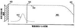
[0011] U.S. Pat. No. 5,942,102(“'102特許”)は、従来法の分析のあいだの、測定出力電流と時間との間の関係について記述する。電気的シグナルは、全血サンプルをストリップに対して導入してから約60秒後の、センサストリップに対する入力である。最初は、急速に減少する電流が観察され、その後比較的一定になるか、またはカウンタ電極から作用電極へのメディエータのフィードバックにより生成される“定常状態” 電流出力が観察される。電極間の短い距離により提供されるメディエータのフィードバックの結果、最初の低下の後、実質的には時間とは無関係になる電流が生じる。この従来法での分析において、サンプルの分析対象物濃度を、メディエータの濃度および拡散係数から以下の様にして決定することができる:(1)時間の関数として電流を測定し;そして次いで(2)定常状態電流を推定する。 [0011] U.S. Pat. No. 5,942,102 ("the '102 patent") describes the relationship between measured output current and time during conventional analysis. The electrical signal is an input to the sensor strip about 60 seconds after the whole blood sample is introduced to the strip. Initially, a rapidly decreasing current is observed, followed by a “steady state” current output that is relatively constant or that is generated by mediator feedback from the counter electrode to the working electrode. The mediator feedback provided by the short distance between the electrodes results in a current that becomes substantially time independent after the initial drop. In this conventional analysis, the analyte concentration of the sample can be determined from the mediator concentration and diffusion coefficient as follows: (1) measure the current as a function of time; and then (2 ) Estimate steady state current.
[0012] '102特許に記載される分析方法は、電流減衰の定常状態部分に依存するが、一方U.S. Pat. Nos. 6,153,069(“'069特許”)および6,413,411(“'411特許”)は、メディエータの濃度、従ってそれを裏打ちする分析対象物の濃度、が、メディエータの拡散係数から決定される場合の方法を記載する。これらのシステムは、Cottrellの式により記述される電流減衰の速度を提供する様に構成される。 [0012] The analytical method described in the '102 patent relies on the steady state portion of current decay, while US Pat. Nos. 6,153,069 (“the' 069 patent”) and 6,413,411 (the “'411 patent”) A method is described where the concentration of the mediator, and hence the concentration of the analyte backing it, is determined from the diffusion coefficient of the mediator. These systems are configured to provide the rate of current decay described by the Cottrell equation.
[0013] 電流測定は、測定電流が時間の平方根に対して反比例する場合に、Cottrell減衰 を示す。Cottrell減衰を伴う電流測定を、式(1)として以下に示すCottrellの式により記述することができる: [0013] Current measurements show Cottrell decay when the measured current is inversely proportional to the square root of time. Current measurements with Cottrell decay can be described by the following Cottrell equation as equation (1):

ここで、iは測定電流であり;Cbは電気化学的に活性な種の全体の濃度(mol/cm3)であり;Aは電極面積(cm2)であり;F は96,500 coul/相当物のファラデー定数であり;nは相当物/molにおいて移動された電子の数であり;Dは拡散係数(cm2/秒)であり;そしてtは電気化学的反応の時間(秒)である。従って、Cottrellの式は、時間の指数関数として電流を記述し、-0.5の減衰定数または指数係数を有する。Cottrellの式のさらなる詳細およびCottrellの振る舞いに必要とされる境界条件は、Electrochemical Methods: Fundamentals and Applications by Bard and Faulkner (1980)の第5章pp. 136-45に見出すことができる。Where i is the measured current; Cb is the total concentration (mol / cm3 ) of the electrochemically active species; A is the electrode area (cm2 ); F is 96,500 coul / equivalent The Faraday constant of the object; n is the number of electrons transferred in equivalents / mol; D is the diffusion coefficient (cm2 / sec); and t is the time of the electrochemical reaction (seconds) . Thus, the Cottrell equation describes the current as an exponential function of time and has a decay constant or exponential coefficient of -0.5. Further details of Cottrell's formula and the boundary conditions required for Cottrell's behavior can be found in Chapter 5 pp. 136-45 of Electrochemical Methods: Fundamentals and Applications by Bard and Faulkner (1980).
[0014] Cottrell電流減衰で動作する様に設計されたシステムは、-0.5の減衰定数を必要とする。-0.5減衰定数を示す電気化学的システムは、Cottrell電流の必要条件が存在すること、すなわち分析対象物が測定可能な種に完全に変換されたこと、そしてこの測定可能な種の実質的に一定の濃度分布が電流測定の前にサンプル容器を占有していること、を暗示している。これらの必要条件は、'069特許および'411特許においてさらに記載される。 [0014] A system designed to operate with Cottrell current decay requires a decay constant of -0.5. An electrochemical system exhibiting a -0.5 decay constant indicates that there is a requirement for the Cottrell current, ie that the analyte has been completely converted to a measurable species, and that this measurable species is substantially constant. This implies that the concentration distribution occupies the sample container prior to the current measurement. These requirements are further described in the '069 and' 411 patents.
[0015] '411特許の第4欄、39〜40行に、15〜90秒間、好ましくは20〜45秒間の最初のインキュベーション期間を、グルコース試験のために使用することが開示される。最初のインキュベーション期間および単一励起入力シグナルの印加の後、Cottrell減衰を示す電流測定を、2〜30秒間、または好ましくは10〜20秒間記録し、その後センサストリップに対して入力シグナルを印加することができる。より長い最初のインキュベーション期間の必要条件もまた、'411特許の図7に示されており、ここでサンプルを160秒間センサストリップ中で反応させ(インキュベートし)、その後入力シグナルの印加を行わせる。 [0015] In
[0016] 分析対象物を測定可能な種に完全に変換するために必要とされるより長いインキュベーション期間は、以下のものをもたらす:(1)試薬を含有する試薬層の水和のための時間;そして(2)分析対象物を変換するための試薬のための時間。例えば、'411特許の第4欄36〜44行には、酵素反応が完了に達することができる十分な長さのインキュベーション期間が記載されている。グルコース分析対象物が測定可能な種へと完全に変換されるこのインキュベーション期間ののち、装置が既知の電位を電極間に負荷して、結果として生じるCottrell電流減衰のあいだの特定の時間、得られた拡散限界の(すなわちCottrell)電流を測定する。このように、分析対象物を測定可能な種に変換することは、Cottrell減衰が観察されるよりも前に完了する。試薬層の完全な水和もまた、Cottrell減衰の必要条件として'411特許中で認識されている。'411特許は、試薬の不完全な湿潤は、結果としてシステムがCottrell曲線減衰を追跡することを不可能にし、結果として不正確な分析対象物濃度値が得られることを開示している。 [0016] The longer incubation period required to completely convert the analyte to a measurable species results in: (1) Time for hydration of the reagent layer containing the reagent And (2) time for a reagent to convert the analyte. For example,
[0017] 延長されたインキュベーション期間に加えて、Cottrell減衰もまた、電極表面からの距離が増加するため、サンプル中の測定可能な種の実質的に一定の濃度分布を必要とする。実質的に一定の濃度分布は、(1)相対的に大きなサンプル容量;および/または(2)表面平面電極または実質的に平面な電極とセンサストリップの蓋の底部表面との間の相対的に大きな距離;により達成することができる。例えば、'069特許の第8欄40行には、50μLのサンプル容量をもたらすサンプル容器をしめる作用電極が記載されており、ここで作用電極と蓋との間の垂直距離は500〜2000μmである。別の例において、'102特許の近接した間隔の電極とは異なり、'411特許の第7欄62〜66行に記載される作用電極とカウンタ電極との距離は、少なくとも100μmであり、そして好ましくは100μm以上でなければならない。 [0017] In addition to the extended incubation period, Cottrell decay also requires a substantially constant concentration distribution of measurable species in the sample due to the increased distance from the electrode surface. A substantially constant concentration distribution can be achieved by: (1) a relatively large sample volume; and / or (2) a relative between a surface planar electrode or a substantially planar electrode and the bottom surface of the sensor strip lid. Can be achieved by large distances. For example,
[0018] 従来法の分析方法は、システムがCottrell減衰を有することを可能にするために十分なインキュベーション期間、電極距離、そしてサンプル容器容量を必要とすることにより、典型的には、サンプルを解析するために必要とされる時間を長くする。従って、改良されたバイオセンサについての継続的な要望が存在する;特に、サンプルの分析対象物濃度をより迅速に測定するもの、そして定常状態電流値の推定に基づくものではないもの、が求められている。本発明のシステム、装置および方法は、従来型のバイオセンサに関する少なくとも1つの欠点を克服する。 [0018] Conventional analysis methods typically analyze samples by requiring sufficient incubation period, electrode distance, and sample container volume to allow the system to have Cottrell decay. Increase the time required to do. Therefore, there is a continuing need for improved biosensors; in particular, what requires more rapid determination of sample analyte concentration and is not based on estimation of steady state current values. ing. The systems, devices and methods of the present invention overcome at least one drawback associated with conventional biosensors.
[0019] 本発明は、過渡減衰を有する出力シグナルから生物学的サンプルの分析対象物濃度を測定するバイオセンサシステムを提供する。出力シグナルは、時間の平方根に反比例せず、そして従ってCottrell減衰の減衰定数よりも高いかまたは低い減衰定数を有する。 [0019] The present invention provides a biosensor system for measuring an analyte concentration of a biological sample from an output signal having transient decay. The output signal is not inversely proportional to the square root of time and therefore has a decay constant that is higher or lower than the decay constant of the Cottrell decay.
[0020] 一側面において、サンプル中の分析対象物濃度を測定するための方法には、インキュベーション期間の後にサンプルに対して入力シグナルを印加し、測定可能な種のレドックス反応に応じた過渡減衰(一過性減衰)を有する出力シグナルを生成し;そして出力シグナルから分析対象物濃度を測定する;ことが含まれる。分析対象物はグルコースであってもよく、そしてサンプルをセンサストリップに対して導入することができる。この方法には、サンプル中の分析対象物からまたは分析対象物へ少なくとも1つの電子を移動させて、少なくとも1つのメディエータが含まれてもよい測定可能な種を形成することが含まれてもよい。 [0020] In one aspect, a method for measuring an analyte concentration in a sample includes applying an input signal to the sample after an incubation period and transient decay (in response to a measurable species redox reaction). Generating an output signal with a transient decay; and measuring the analyte concentration from the output signal. The analyte can be glucose and a sample can be introduced to the sensor strip. The method may include transferring at least one electron from or to the analyte in the sample to form a measurable species that may include at least one mediator. .
[0021] 入力シグナルには、緩和により間隔をあけた少なくとも2回の励起が含まれていてもよく、その場合、少なくとも2回の励起は0.1〜5秒間の期間を有し、そして緩和の期間は少なくとも0.1秒または少なくとも0.5秒である。各励起期間および/または緩和期間は、同一であっても異なっていてもよい。1またはそれ以上の緩和のための期間は、0.1〜3秒間であってもよい。入力シグナルには、少なくとも3回の励起と少なくとも2回の緩和が含まれていてもよい。入力シグナルには、5秒間のあいだに印加される少なくとも2回の負荷サイクルが含まれていてもよい。 [0021] The input signal may include at least two excitations spaced by relaxation, in which case at least two excitations have a period of 0.1 to 5 seconds, and the period of relaxation Is at least 0.1 seconds or at least 0.5 seconds. Each excitation period and / or relaxation period may be the same or different. The period for one or more relaxations may be 0.1 to 3 seconds. The input signal may include at least 3 excitations and at least 2 relaxations. The input signal may include at least two duty cycles applied for 5 seconds.
[0022] インキュベーション期間は、例えば、0.1〜8秒間、0.1〜6秒間、または0.5〜4.75秒間であってもよい。インキュベーション期間および入力シグナルの印加は、最大でも12秒間、最大でも6秒間、または最大でも4秒間で完了することができる。過渡減衰は、-0.52〜-1、または-0.001〜-0.48の減衰定数を有していてもよい。過渡減衰は、最大でも-0.45または最大でも-0.35の減衰定数を有していてもよい。分析対象物濃度を測定する出力シグナルには、サンプルへ入力シグナルを印加してから2秒間以内に記録された電流値が含まれていてもよい。サンプルの分析対象物濃度は、最大でも入力シグナルを印加してから6秒間、3秒間、または1.5秒間以内に測定することができる。 [0022] The incubation period may be, for example, 0.1 to 8 seconds, 0.1 to 6 seconds, or 0.5 to 4.75 seconds. The incubation period and application of the input signal can be completed in a maximum of 12 seconds, a maximum of 6 seconds, or a maximum of 4 seconds. The transient attenuation may have an attenuation constant of -0.52 to -1 or -0.001 to -0.48. The transient attenuation may have an attenuation constant of at most -0.45 or at most -0.35. The output signal for measuring the analyte concentration may include a current value recorded within 2 seconds after the input signal is applied to the sample. The analyte concentration of the sample can be measured at most within 6 seconds, 3 seconds, or 1.5 seconds after applying the input signal.
[0023] サンプルは、蓋の底部表面と蓋の底部表面から20〜200μm離れているセンサストリップ基板とにより規定される容器中に存在することができる。容器中のサンプル容量は、0.25〜10μLであってもよく、0.25〜1.5μLであってもよい。容器には、最大でも20μm、14μm未満、または最大でも5μmの平均初期厚を有する少なくとも1つの試薬層が含まれていてもよい。入力シグナルに少なくとも2回の励起が含まれ、励起の少なくとも一方が最大でも0.5秒間の期間を有する場合、容器には、最大でも2μmの平均初期厚を有する少なくとも1つの試薬層が含まれていてもよい。容器には、別個の拡散バリア層を含む少なくとも1つの試薬層が含まれていてもよい。 [0023] The sample may be present in a container defined by a bottom surface of the lid and a sensor strip substrate that is 20-200 μm away from the bottom surface of the lid. The sample volume in the container may be 0.25 to 10 μL or 0.25 to 1.5 μL. The container may include at least one reagent layer having an average initial thickness of at most 20 μm, less than 14 μm, or at most 5 μm. If the input signal includes at least two excitations and at least one of the excitations has a duration of at most 0.5 seconds, the container contains at least one reagent layer having an average initial thickness of at most 2 μm. Also good. The container may include at least one reagent layer that includes a separate diffusion barrier layer.
[0024] センサストリップ基板から蓋の底部までの容器の高さは、最大でも250μmであってよく、容器内のサンプル容量は最大でも5μLであってよく、容器には最大でも20μmの平均初期厚を有する少なくとも1つの試薬層が含まれていてもよく、そしてインキュベーション期間は最大でも12秒間であってよい。センサストリップ基板から蓋の底部までの容器の高さは、最大でも150μmであってよく、容器内のサンプル容量は最大でも3.5μLであってよく、容器には14μm未満の平均初期厚を有する少なくとも1つの試薬層が含まれていてもよく、そしてインキュベーション期間は最大でも6秒間であってよい。センサストリップ基板から蓋の底部までの容器の高さは最大でも100μmであってよく、容器内のサンプル容量は最大でも3μLであってよく、容器には最大でも2μmの平均初期厚を有する少なくとも1つの試薬層が含まれていてもよく、そしてインキュベーション期間は最大でも2秒間であってよい。 [0024] The height of the container from the sensor strip substrate to the bottom of the lid may be at most 250 μm, the sample volume in the container may be at most 5 μL, and the container has an average initial thickness of at most 20 μm. And at least one reagent layer having an incubation period of up to 12 seconds. The height of the container from the sensor strip substrate to the bottom of the lid may be at most 150 μm, the sample volume in the container may be at most 3.5 μL, and the container has at least an average initial thickness of less than 14 μm One reagent layer may be included and the incubation period may be up to 6 seconds. The height of the container from the sensor strip substrate to the bottom of the lid can be at most 100 μm, the sample volume in the container can be at most 3 μL, and the container has an average initial thickness of at least 2 μm. One reagent layer may be included and the incubation period may be at most 2 seconds.
[0025] 別の側面において、サンプル中の分析対象物濃度を測定するための方法には、最大でも12秒間のインキュベーション期間の後にサンプルに対して入力シグナルを印加し、測定可能な種のレドックス反応に応じた過渡減衰を有する出力シグナルを発生させ;そして出力シグナルから分析対象物濃度を測定することが含まれる。 [0025] In another aspect, a method for measuring an analyte concentration in a sample includes applying an input signal to the sample after an incubation period of at most 12 seconds to measure a redox reaction of a measurable species. Generating an output signal having a transient decay in response to and measuring an analyte concentration from the output signal.
[0026] 別の側面において、サンプル中の分析対象物濃度を測定するためのバイオセンサには、センサインターフェースに接続されたプロセッサを有する測定装置;基板上にサンプルインターフェースを有するセンサストリップが含まれ、ここでセンサインターフェースはサンプルインターフェースと電気的に連通しており、サンプルインターフェースは基板により形成される容器に隣接し;最大でも12秒間のインキュベーション期間の後、プロセッサは充電器に容器に対して入力シグナルを印加する様に指示し;そしてプロセッサは、サンプル中の分析対象物のレドックス反応に応じて、過渡減衰を有する出力シグナルからサンプル中の分析対象物濃度を測定する。 [0026] In another aspect, a biosensor for measuring an analyte concentration in a sample includes a measurement device having a processor connected to a sensor interface; a sensor strip having a sample interface on a substrate; Here, the sensor interface is in electrical communication with the sample interface, which is adjacent to the container formed by the substrate; after an incubation period of at most 12 seconds, the processor sends an input signal to the charger to the container. And the processor measures the analyte concentration in the sample from the output signal with transient decay in response to the redox response of the analyte in the sample.
[0027] 容器には、充電器と電気的に連通した少なくとも1つの作用電極、約1μm〜約20μmの平均初期厚を有する組合せDBL/試薬層を有する作用電極上の試薬層が含まれていてもよい。組合せDBL/試薬層は、最大でも1μmの平均初期厚を有することができる。 [0027] The container includes a reagent layer on the working electrode having at least one working electrode in electrical communication with the charger, a combined DBL / reagent layer having an average initial thickness of about 1 μm to about 20 μm. Also good. The combined DBL / reagent layer can have an average initial thickness of at most 1 μm.
[0028] 別の側面において、サンプル中の分析対象物濃度を測定するための方法には、最大でも12秒間のインキュベーション期間の後に、サンプルに対して入力シグナルを印加し;サンプル容器中で測定可能な種の様々な濃度分布を生成し;測定可能な種のレドックス反応に応じた出力シグナルを生成し;そして出力シグナルから分析対象物濃度を測定すること、が含まれる。 [0028] In another aspect, a method for measuring an analyte concentration in a sample applies an input signal to the sample after an incubation period of at most 12 seconds; can be measured in a sample container Generating various concentration distributions of the species; generating an output signal in response to a measurable species redox reaction; and measuring the analyte concentration from the output signal.
[0029] 別の側面において、サンプル中の分析対象物濃度を測定するための方法には、センサストリップに対してサンプルを導入し;最大でも8秒間のインキュベーション期間の後、入力シグナルをサンプルに対して印加し;測定可能な種のレドックス反応に応じて、過渡減衰を有する出力シグナルを生成し;そして出力シグナルの過渡減衰から分析対象物濃度を測定すること、が含まれる。過渡減衰は、サンプルに対して入力シグナルを印加してから0.5〜5秒間以内、または約0.5〜約3秒間で得られた減少する電流減衰であってもよい。 [0029] In another aspect, a method for measuring an analyte concentration in a sample introduces the sample to the sensor strip; after an incubation period of at most 8 seconds, the input signal is applied to the sample Generating an output signal with a transient decay in response to a measurable species redox reaction; and measuring the analyte concentration from the transient decay of the output signal. The transient decay may be a decreasing current decay obtained within 0.5-5 seconds of applying an input signal to the sample, or from about 0.5 to about 3 seconds.
[0030] 本発明を、以下の図面および説明を参照することにより、より良く理解することができる。図中の構成要素は、必ずしも等縮尺ではなく、代わりに、本発明の原理を示す際に強調されている場合がある。さらに、図中において、同じ参照番号は、異なる図面を通じて対応する部分を一般的に示す。
[0045] バイオセンサシステムは、Cottrell減衰定数を伴わない電気化学的プロセスを使用して、生物学的サンプルの分析対象物濃度を測定する。バイオセンサシステムは、過渡減衰を有する生物学的サンプルから出力シグナルを生成し、この場合、出力シグナルは時間の平方根に反比例しない。バイオセンサシステムからの過渡減衰(一過性減衰)出力は、-0.5よりも大きいかまたはそれよりも小さい減衰定数を有し、そしてこのシステムは、分析対象物濃度を測定するために、定常状態電流値の推定に依存しない。好ましくは、分析対象物濃度を測定する過渡減衰は、連続的に減少する。 [0045] The biosensor system measures the analyte concentration of a biological sample using an electrochemical process without a Cottrell decay constant. The biosensor system generates an output signal from a biological sample that has a transient decay, where the output signal is not inversely proportional to the square root of time. The transient decay (transient decay) output from the biosensor system has a decay constant that is greater than or less than -0.5, and the system is in a steady state to measure analyte concentration It does not depend on current value estimation. Preferably, the transient decay that measures the analyte concentration decreases continuously.
[0046] Cottrell減衰は、拡散依存性であり、そして分析対象物が測定可能な種に完全には変換されず、そしてこの測定可能な種の実質的に一定の濃度分布が電流測定の前にサンプル容器をしめない場合、Cottrell減衰は存在しない可能性がある。比較的長いインキュベーション時間および多い量のサンプル容量が、Cottrell減衰を得るためには必要とされる。これらの条件がない場合には、出力電流は時間の平方根に関して反比例せず、そして従ってバイオセンサはCottrell減衰のために必要とされる-0.5の減衰定数を示さない。出力電流が時間の平方根に関して反比例しない場合または-0.5以外の減衰定数が出力シグナル中に存在する場合、Cottrell減衰を用いて操作するためにデザインされたバイオセンサは、不正確な解析をもたらす。 [0046] Cottrell decay is diffusion dependent and the analyte is not completely converted to a measurable species, and a substantially constant concentration distribution of this measurable species is measured prior to the current measurement. If the sample container is not clamped, the Cottrell decay may not be present. A relatively long incubation time and a large amount of sample volume is required to obtain Cottrell decay. In the absence of these conditions, the output current is not inversely proportional to the square root of time, and thus the biosensor does not exhibit the -0.5 decay constant required for Cottrell decay. If the output current is not inversely proportional to the square root of time, or if an attenuation constant other than -0.5 is present in the output signal, a biosensor designed to operate with Cottrell attenuation will result in inaccurate analysis.
[0047] 本発明のバイオセンサシステムは、過渡減衰を使用して操作し、ここで-0.5よりも小さな減衰定数または-0.5よりも大きな減衰定数が観察される。一過性の従って非-Cottrell減衰定数は、結果として相対的に短いインキュベーション期間から得られる可能性がある。過渡減衰定数もまた、相対的に小さなサンプル容器容量、電極表面とセンサストリップの蓋との間の相対的に短い距離、および/または試薬層の平均初期厚に関して相対的に短い励起から得られる可能性がある。 [0047] The biosensor system of the present invention operates using transient attenuation, where an attenuation constant less than -0.5 or an attenuation constant greater than -0.5 is observed. A transient and therefore non-Cottrell decay constant may result from a relatively short incubation period. Transient decay constants can also be obtained from a relatively small excitation with respect to a relatively small sample vessel volume, a relatively short distance between the electrode surface and the sensor strip lid, and / or an average initial thickness of the reagent layer There is sex.
[0048] 過渡減衰を伴う出力電流または-0.5よりも大きいかまたは小さい過渡減衰定数を生成するため、バイオセンサシステムは、12秒間またはそれ未満のインキュベーション期間、5μLまたはそれ未満の容器容量、200μmまたはそれ未満の容器高、および/または20μmまたはそれ未満の試薬層についての平均初期厚を、使用することができる。3.5μLまたはそれ未満の容器容量、150μmまたはそれ未満の容器高、および/または10μmまたはそれ未満の試薬層についての平均初期厚と共に使用するための好ましいインキュベーション期間は、最大でも8秒間、最大でも6秒間、または最大でも4秒間である。現時点では、3.0μLまたはそれ未満のサンプルストリップサンプル容量、100μmまたはそれ未満のサンプルストリップキャップ-ギャップ高、および/または2μmまたはそれ未満の試薬層についての平均初期厚、と共に使用するための特に好ましいインキュベーション期間は、最大でも2秒間または最大でも1秒である。その他のインキュベーション期間、容器容量、容器高、および試薬層厚を使用することができる。 [0048] To produce an output current with transient decay or a transient decay constant greater than or less than -0.5, the biosensor system has an incubation period of 12 seconds or less, a container volume of 5 μL or less, 200 μm or Lower container heights and / or average initial thicknesses for reagent layers of 20 μm or less can be used. Preferred incubation periods for use with a container volume of 3.5 μL or less, a container height of 150 μm or less, and / or an average initial thickness for a reagent layer of 10 μm or less are at most 8 seconds and at most 6 Seconds, or at most 4 seconds. Currently preferred incubation for use with sample strip sample volumes of 3.0 μL or less, sample strip caps of 100 μm or less-gap height, and / or average initial thickness for reagent layers of 2 μm or less The duration is at most 2 seconds or at most 1 second. Other incubation periods, container volumes, container heights, and reagent layer thicknesses can be used.
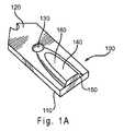
[0049] 図1Aおよび図1Bは、バイオセンサとともに使用することができるセンサストリップ100を示す。図1Aは、組み立てられたセンサストリップ100の透視図であり、蓋120により少なくとも部分的に覆われたセンサ基板110を含み、蓋120には穴130、サンプルカバー領域140、および、投入端開口部150が含まれる。部分的に囲まれたサンプル容器160(キャピラリーギャップまたはキャップ-ギャップ)は、基板110と蓋120との間に形成される。アメリカ合衆国特許第5,120,420号および第5,798,031号に記述されるものなど、その他のセンサストリップ設計もまた、使用することができる。具体的な構造は図1A〜1B中に示されるが、センサストリップ100は、追加の構成成分を伴うものを含むその他の構造を有するものであってもよい。 [0049] FIGS. 1A and 1B show a
[0050] センサ基板110と蓋120との間の容器160の高さは、20〜250μmであってもよく、より好ましくは50〜150μmであってもよい。容器160の容量は、0.25〜10μLであってもよく、好ましくは0.8〜4μLであってもよく、そしてより好ましくは0.5〜1.5μLであってもよい。その他の高さおよび容量を使用することができる。 [0050] The height of the
[0051] 分析のための液体サンプルは開口部150へ液体を導入することにより、容器160へと移すことができる。液体は、先に含まれていた空気を穴130から押し出しながら、容器160を満たす。容器160は、容器中に液体サンプルを保持することを補助する組成物(示されていない)を含むことができる。そのような組成物の例には、カルボキシメチルセルロースおよびポリエチレングリコールなどの水膨潤性ポリマー;および、デキストランおよびポリアクリルアミドなどの多孔性ポリマーマトリクスが含まれる。 [0051] A liquid sample for analysis can be transferred to the
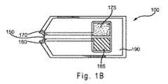
[0052] 図1Bは、蓋120を外したセンサストリップ100の上面図を示す。導体170および180は、開口部150からそれぞれ作用電極175およびカウンタ電極185へと誘電層190の下を走行することができる。センサストリップ100には、1つより多い作用電極が含まれてもよい。作用電極175およびカウンタ電極185は、実質的に同一平面に存在することができる。電極は別の向きであってもよい。誘電層190は、部分的に電極175、185を覆うことができ、そして、絶縁ポリマーなどの適当な誘電物質から作ることができる。具体的な電極構造が示される一方で、電極は、追加の構成要素を有するものを含む、その他の構造を有していてもよい。 [0052] FIG. 1B shows a top view of
[0053] カウンタ電極185は、センサストリップ100の作用電極175における電気化学的活性を補佐することができる。作用電極175における電気化学的活性を補佐する電位は、カウンタ電極185を炭素などの不活性物質から形成すること、および、容器160内にフェリシアン化物(ferricyanide)などの可溶性酸化還元種を含ませることにより、センサ系に提供されることができる。カウンタ電極185における電位は、Ag/AgClなどの酸化還元ペアからカウンタ電極185を形成することにより達せられる参照電位であってよく、組み合わさった参照-カウンタ電極を提供する。酸化還元対には、異なる酸化数を有する化学物質の2つの複合体種が含まれる。より高い酸化数を有する種の還元は、より低い酸化数を有する種を生成する。あるいは、より低い酸化数を有する種の酸化は、より高い酸化数を有する種を生成する。センサストリップ100には、第三導体および第三電極とを提供して、センサ系に参照電位を提供することができる。 [0053] The
[0054] 作用電極175とカウンタ電極185は、200μmよりも遠くまたは250μmよりも遠く離れていてもよい。作用電極175とカウンタ電極185は、200μm未満の距離で離れていてもよい。作用電極175とカウンタ電極185は、それ以外の距離で離れていてもよい。 [0054] The working
[0055] 図2Aは、容器160中に存在する作用電極175およびカウンタ電極185の層構造を示す図1Bに示されるセンサストリップ100の端面図を示す。導体170および180は、基板110上に直接載せることができる。その他の物質が、導体170、180と基板110との間に存在してもよく、従って導体は、基板と物理的に接触していてもしていなくてもよい。導体の一部は、基板の一部を貫通していてもよい。表面導体層270および280は、それぞれ導体170および180の上に、場合によっては沈着することができる。その他の物質が、表面導体層270、280および導体170、180のあいだに存在してもよく、従って表面導体は導体と物理的に接触していてもしていなくてもよい。表面導体の一部は、導体の一部を貫通していてもよい。表面導体層270、280は、同じ物質からまたは異なる物質から作ることができる。 [0055] FIG. 2A shows an end view of the
[0056] 導体170、180、および表面導体層270、280を形成するために使用される、1つあるいは複数の物質は、すべての電導体を含むことができる。導体170、180には、好ましくは、金、銀、白金、パラジウム、銅、またはタングステンなどの、金属または金属ペーストの薄い層が含まれる。表面導体層270、280には、好ましくは炭素、金、白金、パラジウム、またはそれらの組み合わせが含まれる。好ましい電導体は非イオン化物質であり、そのためその物質は、サンプルの分析の間に、正味の酸化、または、正味の還元を受けない。表面導体層が導体上に存在しない場合、導体は、好ましくは非イオン化物質(例えば、炭素、金、プラチナ、パラジウム、またはこれらの組合せ)から作られる。 [0056] The material or materials used to form the
[0057] 箔蒸着、化学気相蒸着、スラリー塗布などを含む、センサストリップの操作と互換性のある従来のすべての手法によって、表面導体物質を、導体170、180上に沈着することができる。アメリカ合衆国特許第5,798,031号に記述される通り、スラリー蒸着の場合、導体物質をインクとして導体170、180に適用することができる。 [0057] The surface conductor material can be deposited on the
[0058] 試薬層275および285を、それぞれ導体170および180上に沈着することができる。その層は、接着剤を含んでいてもよく、少なくとも1つの試薬組成物から形成される。接着剤は、好ましくは、少なくとも部分的に水溶性のポリマー物質である。接着剤は、水和されると、ゲルまたはゲル状物質を形成することができる。接着剤は、水和されると、試薬と組み合わされて、ゲルまたはゲル状物質を形成することができる。ゲルまたはゲル状物質は、赤血球を阻害しおよび/または濾過して、表面導体270および/または導体170へ到達することを防止する。 [0058] Reagent layers 275 and 285 may be deposited on
[0059] 接着剤としての使用に適する、部分的に水溶性のポリマー物質には、ポリ(エチレンオキシド)(PEO)、カルボキシメチルセルロース(CMC)、ポリビニルアルコール(PVA)、ヒドロキシエチレンセルロース(HEC)、ヒドロキシプロピルセルロース(HPC)、メチルセルロース、エチルセルロース、エチルヒドロキシエチルセルロース、カルボキシメチルエチルセルロース、ポリビニルピロリドン(PVP)、ポリリジンなどのポリアミノ酸、ポチスチレンスルホン酸、ゼラチン、アクリル酸、メタアクリル酸、でんぷん、それらの無水マレイン酸塩、それらの誘導体、およびそれらの組み合わせが含まれてもよい。上記の接着剤物質の中で、PEO、PVA、CMC、およびHECが好ましく、現在のところ、CMCがより好ましい。 [0059] Partially water-soluble polymeric materials suitable for use as adhesives include poly (ethylene oxide) (PEO), carboxymethyl cellulose (CMC), polyvinyl alcohol (PVA), hydroxyethylene cellulose (HEC), hydroxy Polyamino acids such as propylcellulose (HPC), methylcellulose, ethylcellulose, ethylhydroxyethylcellulose, carboxymethylethylcellulose, polyvinylpyrrolidone (PVP), polylysine, polystyrene sulfonic acid, gelatin, acrylic acid, methacrylic acid, starch, and their maleic anhydride Acid salts, derivatives thereof, and combinations thereof may be included. Of the above adhesive materials, PEO, PVA, CMC, and HEC are preferred, with CMC being more preferred at present.
[0060] 接着剤に加えて、試薬層275および285には、同一の試薬、または異なる試薬が含まれてよい。同一の試薬が含まれる場合、試薬層275および285は同一の層であってよい。1つの観点において、第一層275中に存在する試薬を、作用電極175と共に使用するために選択することができ、一方、第二層285中に存在する試薬を、カウンタ電極185と共に使用するために選択することができる。例えば、層285中の試薬は、サンプルと導体180との間の電子の流れを促進することができる。同様に、層275中の試薬は、分析対象物の反応を促進することができる。 [0060] In addition to the adhesive, the reagent layers 275 and 285 may include the same reagent or different reagents. When the same reagent is included, reagent layers 275 and 285 may be the same layer. In one aspect, the reagent present in the first layer 275 can be selected for use with the working
[0061] 試薬層275には、分析対象物、特に複雑な生物学的サンプル中の分析対象物、へのセンサ系の特異性を高めることができる、分析対象物に特異的な酵素系を含むことができる。酵素系には、1つあるいはそれ以上の酵素、補因子、および/または、分析対象物との酸化還元反応に参加するその他の部分を含むことができる。例えば、アルコールオキシダーゼを使用して、サンプル中のアルコールの存在に対して感度の高いセンサストリップを提供することができる。そのような系は、血液アルコール濃度を測定するのに有用であるだろう。別の例では、グルコースデヒドロゲナーゼまたはグルコースオキシダーゼを使用して、サンプル中のグルコースの存在に対して感度の高いセンサストリップを提供することができる。この系は、例えば糖尿病であることが既知の患者、または、疑われる患者において、血液グルコース濃度を測定する際に有用であるだろう。 [0061] The reagent layer 275 includes an analyte system specific to the analyte that can increase the specificity of the sensor system to the analyte, particularly the analyte in complex biological samples. be able to. The enzyme system can include one or more enzymes, cofactors, and / or other moieties that participate in redox reactions with the analyte. For example, alcohol oxidase can be used to provide a sensor strip that is sensitive to the presence of alcohol in the sample. Such a system would be useful for measuring blood alcohol concentration. In another example, glucose dehydrogenase or glucose oxidase can be used to provide a sensor strip that is sensitive to the presence of glucose in a sample. This system may be useful in measuring blood glucose levels, for example in patients known or suspected of having diabetes.
[0062] 酵素系において使用される酵素には、アルコールデヒドロゲナーゼ、乳酸脱水素酵素、β-ヒドロキシ酪酸脱水素酵素、グルコース-6-リン酸デヒドロゲナーゼ、グルコースデヒドロゲナーゼ、ホルムアルデヒドデヒドロゲナーゼ、リンゴ酸脱水素酵素、および3-ヒドロキシステロイド脱水素酵素が含まれる。好ましい酵素系は、酸素非依存性であり、つまり、実質的に酸素により酸化されない。 [0062] Enzymes used in the enzyme system include alcohol dehydrogenase, lactate dehydrogenase, β-hydroxybutyrate dehydrogenase, glucose-6-phosphate dehydrogenase, glucose dehydrogenase, formaldehyde dehydrogenase, malate dehydrogenase, and 3-hydroxysteroid dehydrogenase is included. Preferred enzyme systems are oxygen independent, ie, are not substantially oxidized by oxygen.
[0063] グルコースセンサストリップにおいて使用するためのそのような酸素非依存性酵素ファミリーの1つは、グルコースデヒドロゲナーゼ(GDH)である。異なる補酵素または補因子を使用して、異なるメディエータにより異なる様式で、GDHを媒介することができる。GDHとのその関連性に応じて、フラビンアデニンジヌクレオチド(FAD)などの補因子は、FAD-GDHの場合のように、宿主酵素によってきつく捕えられることができる;あるいは、ピロロキノリンキノン(PQQ)などの補因子は、PQQ-GDHというように、宿主酵素と共有結合することができる。これらの各酵素系の補因子は、宿主細胞により捕えられているか、あるいは、補酵素およびアポ酵素は、試薬組成物に酵素系が加えられる前に再構成することができる。補酵素はまた、試薬組成物中の宿主酵素に独立して加えられ、ニコチンアミドアデニンジヌクレオチドNAD/NADH+またはニコチンアミドアデニンジヌクレオチドリン酸NADP/NADPH+の場合のように、宿主酵素の触媒的機能を補助することができる。[0063] One such oxygen-independent enzyme family for use in glucose sensor strips is glucose dehydrogenase (GDH). Different coenzymes or cofactors can be used to mediate GDH in different ways by different mediators. Depending on their association with GDH, cofactors such as flavin adenine dinucleotide (FAD) can be tightly captured by host enzymes, as in FAD-GDH; or pyrroloquinoline quinone (PQQ) Cofactors such as PQQ-GDH can be covalently linked to a host enzyme. The cofactors for each of these enzyme systems are either captured by the host cell, or the coenzyme and apoenzyme can be reconstituted before the enzyme system is added to the reagent composition. The coenzyme is also added independently of the host enzyme in the reagent composition, and the host enzyme's catalyst, as in the case of nicotinamide adenine dinucleotide NAD / NADH+ or nicotinamide adenine dinucleotide phosphate NADP / NADPH+ Functional functions can be assisted.
[0064] 試薬層275には、分析対象物の酸化還元反応の結果を、表面導体270および/または導体170へ、より効率的に伝えるためのメディエータを含むことができる。メディエータはその電気化学的活性に基づいて、2つのグループに分けることができる。1電子移動メディエータは、電気化学的反応のあいだ、1つのさらなる電子を捕えることができる。1電子移動メディエータの例には、1,1'-ジメチルフェロセン、フェロシアン化物(ferrocyanide)、フェリシアン化物(ferricyanide)などの化合物、およびルテニウム(III)ヘキサアミンが含まれる。2電子移動メディエータは、2つの追加の電子を移動させることができる。 [0064] The reagent layer 275 may include a mediator for more efficiently transmitting the result of the redox reaction of the analyte to the
[0065] 2電子メディエータには、フェナトロリンキノンなどの、有機キノンおよびヒドロキノン;フェノチアジンおよびフェノキサジン誘導体;3-(フェニルアミノ)-3H-フェノキサジン;フェノチアジン;および7-ヒドロキシ-9,9-ジメチル-9H-アクリジン-2-オンおよびその誘導体が含まれる。さらなる2電子メディエータの例には、例えば、本明細書中で参照として援用される、アメリカ合衆国特許第5,393,615号;第5,498,542号;および第5,520,786号に記載される、電子-活性有機分子が含まれる。その他の電気活性な有機分子には、酸化還元反応を受けることができる金属を持たない有機分子が含まれる。電気活性な有機分子は、酸化還元種としておよび/またはメディエータとして、振る舞うことができる。電気活性な有機分子の例には、補酵素ピロロキノリンキノン(PQQ)、ベンゾキノン、およびナフトキノン、N-オキシド、ニトロソ化合物、ヒドロキシルアミン、オキシン、フラビン、フェナジン、フェノチアジン、インドフェノール、およびインダミンが含まれる。 [0065] Two-electron mediators include organic quinones and hydroquinones, such as phenatroline quinone; phenothiazine and phenoxazine derivatives; 3- (phenylamino) -3H-phenoxazine; phenothiazine; and 7-hydroxy-9,9-dimethyl -9H-acridin-2-one and its derivatives are included. Examples of additional two-electron mediators include the electron-active organic molecules described, for example, in US Pat. Nos. 5,393,615; 5,498,542; and 5,520,786, which are incorporated herein by reference. Other electroactive organic molecules include organic molecules that do not have a metal capable of undergoing a redox reaction. Electroactive organic molecules can behave as redox species and / or as mediators. Examples of electroactive organic molecules include the coenzyme pyrroloquinoline quinone (PQQ), benzoquinone, and naphthoquinone, N-oxide, nitroso compounds, hydroxylamine, oxine, flavin, phenazine, phenothiazine, indophenol, and indamine .
[0066] 好ましい2電子移動メディエータには、3-フェニルイミノ-3H-フェノチアジン(PIPT)および3-フェニルイミノ-3H-フェノキサジン(PIPO)が含まれる。より好ましい2電子メディエータには、フェノキサジン誘導体の、カルボン酸または塩(たとえば、アンモニウム塩など)が含まれる。現在のところ、特に好ましい2電子メディエータには、(E)-2-(3H-フェノチアジン-3-イリデンアミノ)ベンゼン-1,4-ジスルホン酸、(E)-5-(3H-フェノチアジン-3-イリデンアミノ)イソフタル酸、アンモニウム(E)-3-(3H-フェノチアジン-3-イリデンアミノ)-5-カルボキシ安息香酸、およびそれらの組み合わせが含まれる。好ましい2電子メディエータは、フェリシアン化物(ferricyanide)よりも少なくとも100 mV低い、好ましくは少なくとも150 mV低い、酸化還元電位を有する。 [0066] Preferred two electron transfer mediators include 3-phenylimino-3H-phenothiazine (PIPT) and 3-phenylimino-3H-phenoxazine (PIPO). More preferred two-electron mediators include carboxylic acids or salts (such as ammonium salts) of phenoxazine derivatives. Currently, particularly preferred two-electron mediators include (E) -2- (3H-phenothiazine-3-ylideneamino) benzene-1,4-disulfonic acid, (E) -5- (3H-phenothiazine-3-ylideneamino ) Isophthalic acid, ammonium (E) -3- (3H-phenothiazine-3-ylideneamino) -5-carboxybenzoic acid, and combinations thereof. Preferred two electron mediators have a redox potential that is at least 100 mV lower, preferably at least 150 mV lower than ferricyanide.
[0067] 印刷、液体沈着、またはインクジェット沈着などの便利な手法により、試薬層275、285を沈着させることができる。1つの観点において、この層は印刷により沈着される。その他の因子が等しい場合、印刷のブレードの角度が、試薬層の厚さに、逆向きに影響する可能性がある。例えば、ブレードが基板110に対して約82°の角度で動かされる場合、この層は約10μmの初期厚を有することができる。同様に、基板110に対して約62°のブレードの角度を使用する場合、より厚い30μmの層を作成することができる。このように、ブレードの角度が低いほど、より厚い試薬層を提供することができる。ブレードの角度に加えて、試薬組成物の粘度や、ふるいサイズ(screen-size)およびエマルション組み合わせ(emulsion combination)などのその他の因子が、試薬層275、285の結果的な厚さに影響を及ぼす可能性がある。 [0067] The reagent layers 275, 285 can be deposited by convenient techniques such as printing, liquid deposition, or ink jet deposition. In one aspect, this layer is deposited by printing. If the other factors are equal, the angle of the printing blade can adversely affect the reagent layer thickness. For example, if the blade is moved at an angle of about 82 ° with respect to the
[0068] より薄い試薬層が好ましい場合、マイクロピペッティング、インクジェッティング、または、ピン-沈着などの、印刷以外の沈着方法を使用することができる。これらの沈着方法は一般に、1〜2μmなどの、マイクロメートルまたはマイクロメートル未満の厚さの乾燥試薬層を与える。例えば、ピン-沈着法は、約1μmの平均初期厚の試薬層を提供することができる。ピン-沈着の結果である試薬層の厚さは、例えば、試薬組成物中に含まれるポリマーの量により調節することができ、ポリマー含有量が高いほどより厚い試薬層を提供する。望ましい測定性能を維持するためおよび/または拡散バリア層(DBL)内の分析対象物を実質的に測定するために、より薄い試薬層は、より厚い試薬層よりも短い励起期間を必要とする可能性がある。 [0068] Where thinner reagent layers are preferred, deposition methods other than printing, such as micropipetting, ink jetting, or pin-deposition can be used. These deposition methods generally provide a dry reagent layer with a thickness of micrometer or submicrometer, such as 1-2 μm. For example, the pin-deposition method can provide a reagent layer with an average initial thickness of about 1 μm. The thickness of the reagent layer that is the result of pin-deposition can be adjusted, for example, by the amount of polymer contained in the reagent composition, with higher polymer content providing a thicker reagent layer. A thinner reagent layer may require a shorter excitation period than a thicker reagent layer to maintain the desired measurement performance and / or to substantially measure the analyte in the diffusion barrier layer (DBL) There is sex.
[0069] 作用電極175には、図2Aに示されるような、試薬層275と一体のものである(integral)DBLか、または、異なる層290であるDBLが含まれていてもよい。つまりDBLを、導体上の試薬/DBLの組み合わせとして、導体上の異なる層として、または、試薬層上の区別される層として、形成することができる。作用電極175が異なるDBL 290を含む場合、試薬層275はDBL 290上に存在してもよいし、存在しなくてもよい。かわりに、試薬層275は、試薬をサンプル中に溶解することができるセンサストリップ100のどの部分にあってもよい。例えば、試薬層175は、基板110にあってもまたは蓋120上にあってもよい。 [0069] The working
[0070] DBLは、測定可能な種が存在できそして赤血球を導体表面から濾過することもできる内部容量を有する、多孔空間を提供する。DBLの孔を、測定可能な種がDBL内に拡散することができるが、赤血球などの物理的に大きなサンプル構成成分は実質的に排除されるように選択することができる。従来のセンサストリップは、様々な物質を用いて作用電極の表面から赤血球を濾過してきたが、DBLは内部多孔空間を提供して、サンプルから測定可能な種の一部分を含有させ、そして分離する。 [0070] DBL provides a porous space with an internal volume where measurable species can be present and red blood cells can also be filtered from the conductor surface. The pores of the DBL can be selected such that measurable species can diffuse into the DBL, but physically large sample components such as red blood cells are substantially excluded. While conventional sensor strips have filtered red blood cells from the surface of the working electrode using a variety of materials, DBL provides an internal porous space to contain and separate measurable species fractions from the sample.
[0071] 試薬層275に水溶性接着剤が含まれる場合、励起の印加に先立ってサンプルに溶解しない接着剤の部分は、一体のDBLとして機能することができる。DBL/試薬層の組み合わせの平均初期厚は、好ましくは、20あるいは10マイクロメートル(μm)より薄く、そしてより好ましくは、5μmより薄い。DBL/試薬層の組み合わせの望ましい平均初期厚は、DBLから、導体表面(図2Aの導体170の表面または表面導体270の表面など)への、測定可能な種の拡散速度が比較的一定になったときを基準にして、特異的な励起の長さにおいて選択されることができる。0.25秒またはそれより短い励起期間と組み合わされる場合、DBL/試薬層の組合せは2μm、1μm、またはそれより薄い、平均初期厚を有することができる。 [0071] When the water-soluble adhesive is included in the reagent layer 275, the part of the adhesive that does not dissolve in the sample prior to the application of excitation can function as an integral DBL. The average initial thickness of the DBL / reagent layer combination is preferably less than 20 or 10 micrometers (μm), and more preferably less than 5 μm. The desired average initial thickness of the DBL / reagent layer combination is such that the measurable species diffusion rate from the DBL to the conductor surface (such as the surface of
[0072] 異なるDBL 290は、望ましい多孔空間を提供するすべての物質を含むことができ、一方、サンプル中に、部分的に、またはゆっくりと溶解する。異なるDBL 290は、試薬のない試薬接着物質を含むことができる。異なるDBL 290は、1〜15μm、また、より好ましくは2〜5μmの平均初期厚を有してもよい。 [0072]
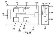
[0073] 図2Bは、生体液などのサンプル中の分析対象物濃度を測定するバイオセンサシステム200のスキーム図を示す。バイオセンサシステム200には、分析方法を行う測定装置202とセンサストリップ204とが含まれる。センサストリップ204は、例えば、図1A、図1B、および図2Aに示すような電気化学的センサストリップであってもよい。測定装置202は、卓上装置、携帯型または手持ち型装置などとして実施することができる。測定装置202およびセンサストリップ204は、電気化学的分析、光学的分析、これらの組合せなどを行うことができる。バイオセンサシステム200は、生物学的サンプル中のアルコール、グルコース、尿酸、乳酸、コレステロール、ビリルビンなどの濃度を含む分析対象物濃度を測定することができる。具体的な構造が示されるが、バイオセンサシステム200は、追加の構成成分を有するものを含め、その他の構造を有していてもよい。 [0073] FIG. 2B shows a schematic diagram of a
[0074] センサストリップ204は、サンプル容器208と開口部212を伴うチャネル210とを形成する基板206を有する。図1Aを参照する場合、チャネル210は、容器208と一体である場合がある。容器208およびチャネル210は、穴が開いた蓋により覆われていてもよい。容器208は、部分的に囲まれた容量(キャップ-ギャップ)を規定する。容器208は、水-膨潤性ポリマーまたは多孔性ポリマーマトリクスなどの液体サンプルを保持することを補助する組成物を含有していてもよい。試薬は、容器208および/またはチャネル210中に入れていてもよい。試薬組成物には、1またはそれ以上の酵素、結合剤、メディエータなどが含まれていてもよい。試薬には、光学系のための化学指示薬が含まれていてもよい。センサストリップ204は、その他の構造を有していてもよい。 [0074] The
[0075] センサストリップ204はまた、サンプルインターフェース214を有していてもよい。電気化学的システムにおいて、サンプルインターフェース214は、少なくとも2つの電極(例えば、作用電極とカウンタ電極)に接続された導体を有する。電極は、容器208を形成する基板206の表面に配置されていてもよい。サンプルインターフェース214は、その他の電極および/または導体を有していてもよい。 [0075] The
[0076] 測定装置202には、センサインターフェース218およびディスプレイ220に接続された電気回路216が含まれる。電気回路216には、シグナル発生器224、光学温度センサ226、および保存媒体228に対して接続されたプロセッサ222が含まれていてもよい。電気回路216は、追加の構成成分を伴うものなどその他の構造を有していてもよい。 [0076] The
[0077] シグナル発生器224は、プロセッサ222に応じて、電気的入力シグナルをセンサインターフェース218に対して提供する。光学システムにおいて、電気的入力シグナルを使用して、センサインターフェース218中の検出器および光源を操作しまたは調節することができる。電気化学的システムにおいて、電気的入力シグナルは、センサインターフェース218によりサンプルインターフェース214へと伝達され、電気的入力シグナルを容器208に対してそして従ってサンプルに対して印加することができる。 [0077] The
[0078] 電気的入力シグナルは、電位であるかまたは電流であってもよく、そして例えば、ACシグナルがDCシグナルオフセットと共に印加される場合など、一定であっても、可変であっても、またはそれらの組合せであってもよい。電気的入力シグナルを単回パルスとしてまたは複数回パルスで、連続的にまたはサイクル状に印加することができる。シグナル発生器224もまた、発生器-記録装置としてセンサインターフェース218からの出力シグナルを記録することができる。 [0078] The electrical input signal may be a potential or a current and may be constant, variable, such as, for example, when an AC signal is applied with a DC signal offset, or A combination thereof may also be used. The electrical input signal can be applied continuously or in cycles, as a single pulse or in multiple pulses. The
[0079] 保存媒体228は、磁気メモリ、光学的メモリ、または半導体メモリ、その他のコンピュータ読み取り可能保存装置などであってもよい。保存媒体228は、固定式のメモリ装置またはメモリカードなどの取り外し可能メモリ装置であってもよい。 [0079] The
[0080] プロセッサ222は、分析対象物分析およびコンピュータ読み取り可能ソフトウェアコードとおよび保存媒体228に保存されたデータとを使用したデータ処理を行うことができる。プロセッサ222は、センサインターフェース218でのセンサストリップ204の存在に応じた分析対象物分析、ユーザ入力に応じたサンプルのセンサストリップ204への適用などを開始することができる。プロセッサ222は、シグナル発生器224に指示を出して、電気的入力シグナルをセンサインターフェース218に対してもたらすことができる。プロセッサ222は、そのように備わっていれば、温度センサ226からサンプル温度を受け取ることができる。 [0080] The
[0081] プロセッサ222は、センサインターフェース218から出力シグナルを受け取る。出力シグナルは、サンプル中の分析対象物のレドックス反応に応じて生成される。出力シグナルは、光学的システム、電気化学的システムなどを使用して生成することができる。プロセッサ222は、相関式を使用して、1またはそれ以上の出力シグナルからサンプル中の分析対象物の濃度を測定することができる。分析対象物分析の結果は、ディスプレイ220へ出力することができ、そして保存媒体228に保存することができる。 [0081] The
[0082] 分析対象物濃度および出力シグナルに関する相関式は、グラフ的に、数学的に、それらの組合せなどで、示すことができる。相関式は、保存媒体228中に保存される、プログラム数割り当て(program number assignment;PNA)表、その他のルックアップ表などにより示すことができる。分析の実施に関する指示は、保存媒体228中に保存されるコンピュータ読み取り可能ソフトウェアコードにより提供することができる。このコードは、オブジェクトコードであっても、または本明細書中に記載される機能性を記述しまたは制御するその他のいずれかのコードであってもよい。分析対象物分析からのデータは、減衰速度の測定、K定数の測定、傾きの測定、切片の測定、および/またはプロセッサ222中のサンプル温度の測定を含む、1またはそれ以上のデータ処理の対象であってもよい。 [0082] Correlation equations for analyte concentration and output signal can be shown graphically, mathematically, combinations thereof, and the like. The correlation equation can be shown by a program number assignment (PNA) table, other lookup tables, etc. stored in the
[0083] 電気化学的システムにおいて、センサインターフェース218は、電気的または光学的にサンプルインターフェース214と連通している。電気的な連通には、センサインターフェース218中の接点とサンプルインターフェース214中の導体との間の、入力シグナルおよび/または出力シグナルの伝達が含まれる。電気的な連通は、例えば、ワイヤレスで行われてもあるいは物理的接点を介して行われてもよい。センサインターフェース218は、電気的入力シグナルを、シグナル発生器224から、接点を介して、サンプルインターフェース214中のコネクタへと伝達する。センサインターフェース218もまた、出力シグナルを、サンプルから接点を介してプロセッサ222および/またはシグナル発生器224へと伝達する。 [0083] In an electrochemical system, the
[0084] 光学的な連通には、サンプルインターフェース202中の光学的入り口とセンサインターフェース208中の検出器との間の光の伝達が含まれる。光学的な連通には、サンプルインターフェース202中の光学的入り口とセンサインターフェース208中の光源との間の光の伝達もまた含まれる。 [0084] Optical communication includes transmission of light between an optical entrance in the
[0085] ディスプレイ220は、アナログであってもデジタルであってもよい。ディスプレイ220は、LCD、LED、または数値的読み取り値を表示する様に改造された真空蛍光ディスプレイであってもよい。 [0085] The
[0086] 使用時には、液体を開口部212に導入することにより、分析用の液体サンプルを容器208中へと移動させる。液体サンプルは、事前に含まれていた空気を押し出しながら、チャネル210を通過して、容器208中へと流される。液体サンプルは、チャネル210および/または容器208中に配置される試薬と化学的に反応する。プロセッサ222は、シグナル発生器224へと向けられ、入力シグナルをセンサインターフェース218に対してもたらす。光学的システムにおいて、センサインターフェース218 は、入力シグナルに応じて、検出器および光源を操作する。電気化学的システムにおいては、センサインターフェース218が、入力シグナルをサンプルインターフェース214を介してサンプルに対してもたらす。プロセッサ222は、サンプル中の分析対象物のレドックス反応に応じて生成される出力シグナルを受け取る。プロセッサ222は、1またはそれ以上の相関式を使用して、サンプルの分析対象物濃度を測定する。測定された分析対象物濃度は、表示してもよくおよび/または将来的な参照のために保存してもよい。 In use, the liquid sample for analysis is moved into the
[0087] 図3は、サンプル312中の分析対象物322の存在そして場合によってはその濃度を測定するための電気化学的分析300のフローチャートを示す。310において、サンプル312が、図1A〜図1Bおよび図2Aにおいて示されるセンサストリップなどのセンサストリップ314に対して導入される。図2Aに示される275および/または285などの試薬層は、サンプル312中に溶解され始め、その結果反応が可能になる。 [0087] FIG. 3 shows a flow chart of an
[0088] 315において、最初のインキュベーション期間317は、入力シグナルが印加される前に、試薬がサンプル312と反応することを可能にする。好ましくは、インキュベーション期間317は、0.1〜10秒間であってよく、より好ましくは0.1〜8秒間または0.5〜4秒間であってもよい。現在は、インキュベーション期間317としては、0.1〜1秒がより好ましい。その他のインキュベーション期間を使用することができる。 [0088] At 315, an initial incubation period 317 allows the reagent to react with the sample 312 before an input signal is applied. Preferably, the incubation period 317 may be 0.1-10 seconds, more preferably 0.1-8 seconds or 0.5-4 seconds. Currently, the incubation period 317 is more preferably 0.1 to 1 second. Other incubation periods can be used.
[0089] インキュベーション期間317のあいだ、サンプル312中に存在する分析対象物322の一部は、320中でレドックス反応により化学的にまたは生化学的に酸化または還元され、測定可能な種332を形成する。測定可能な種332は、酸化されたかまたは還元された分析対象物322であってもよく、またはメディエータであってもよい。酸化または還元に際して、電子が分析対象物322へと移動されるかまたは分析対象物322から移動され、330中の測定可能な種332へと移動されるかまたは330中の測定可能な種332から移動される。例えば、メディエータは還元されて、分析対象物322の酸化を介して測定可能な種332を形成することができる。好ましくは、インキュベーション期間317のあいだに形成される測定可能な種332は、インキュベーション期間317のあいだに電気化学的には励起されない。 [0089] During the incubation period 317, a portion of the analyte 322 present in the sample 312 is chemically or biochemically oxidized or reduced by a redox reaction in 320 to form a measurable species 332. To do. The measurable species 332 may be an oxidized or reduced analyte 322 or may be a mediator. Upon oxidation or reduction, electrons are transferred to or from analyte 322 and transferred to measurable species 332 in 330 or from measurable species 332 in 330. Moved. For example, the mediator can be reduced to form a measurable species 332 via oxidation of the analyte 322. Preferably, the measurable species 332 formed during the incubation period 317 is not electrochemically excited during the incubation period 317.
[0090] 340において、測定可能な種332は、電気化学的に励起される(酸化されまたは還元される)。この様式において、電子は、分析対象物322とセンサストリップ314の作用電極との間を選択的に移動される。励起340は、0.1〜5秒間の期間であってもよく、または0.1〜1秒間の期間であってもよい。励起340を繰り返してもよい。 [0090] At 340, the measurable species 332 is electrochemically excited (oxidized or reduced). In this manner, electrons are selectively transferred between the analyte 322 and the working electrode of the sensor strip 314.
[0091] 350において、励起340のあいだに生成される電流は、時間の関数として記録することができる。複数の励起340がセンサストリップ314に対して印加される場合、励起340から得られる1またはそれ以上の電流を、350において記録することができる。電流を、測定装置により記録することができる。 [0091] At 350, the current generated during
[0092] 360において、サンプルは緩和を受ける。好ましくは、電流を緩和360のあいだは記録しない。複数の励起を印加する場合、緩和360は、励起340のそれぞれの後に行うことができる。緩和360のあいだ、励起340のあいだに存在する電流は、少なくとも半分まで、好ましくは一桁まで、そしてより好ましくはゼロまで、実質的に減少させる。好ましくは、ゼロ電流状態が、開回路によりもたらされるか、または実質的にゼロ電流をもたらすことが当業者に知られているその他の方法によりもたらされる。測定装置は、センサストリップ314を介して回路を開放して、開回路を提供することができる。ゼロ電流状態がもたらされる場合、緩和360は、断続的なインキュベーション期間と考えることができる。 [0092] At 360, the sample undergoes relaxation. Preferably, the current is not recorded during
[0093] 緩和360は、少なくとも0.1秒間の期間または少なくとも0.5秒間の期間であってもよい。緩和360は、0.1〜3秒間の期間、0.2〜2秒間の期間、または0.5〜1秒間の期間であってもよい。その他の緩和期間を使用することができる。 [0093] The
[0094] 370において、1またはそれ以上の記録された350からの電流値および時間値を解析して、サンプル312中の分析対象物322の存在および/または濃度を測定することができる。好ましくは、分析対象物濃度は、最初に印加される励起の開始から2秒間または1秒間以内に行われる電流測定から決定される。より好ましくは、複数の短い励起を最初に印加される入力シグナルから2秒間以内、1秒間以内、またはそれ未満に行われる電流測定と組み合わせて、サンプルの分析対象物濃度を測定する。記録された電流値および時間値を、1またはそれ以上の相関式を使用して、サンプル312中の分析対象物322の濃度と相関させることができる。 [0094] At 370, one or more recorded current and time values from 350 can be analyzed to determine the presence and / or concentration of analyte 322 in sample 312. Preferably, the analyte concentration is determined from a current measurement made within 2 seconds or 1 second from the start of the first applied excitation. More preferably, the analyte concentration of the sample is measured in combination with a current measurement performed within 2 seconds, within 1 second, or less than the first applied input signal of multiple short excitations. The recorded current and time values can be correlated with the concentration of analyte 322 in sample 312 using one or more correlation equations.
[0095] 励起340および緩和360は、一回の負荷サイクルを構成する。好ましくは、センサストリップ314に対して印加される入力シグナルには、独立して選択される3秒、5秒、7秒、または9秒の期間内に印加される、少なくとも2回、4回、または6回の負荷サイクルが含まれる。従って、入力シグナルの最初の印加から、電気化学的分析300の励起340および緩和360の部分のために必要とされる全体の時間は、最大でも3秒間、最大でも5秒間、最大でも7秒間、または最大でも9秒間であってもよい。負荷サイクルは、1〜3秒の期間のあいだ印加することができる。2〜6回の負荷サイクルを8秒間以内の間に印加することができる。2〜4回の負荷サイクルを3〜6秒間以内に印加することができる。その他の期間を使用することができる。 [0095] Excitation 340 and
[0096] 連続的なモニタリングのため、移植されたセンサまたは部分的に移植されたセンサと共に使用する場合と同様に、負荷サイクルを連続的に繰り返すことができる。システムを操作するために必要とされるエネルギーを減少させることができ、そしてそのシステムの耐用年数を緩和を含まない方法に関して延長することができる。さらに、複数の負荷サイクルの印加を、より長い期間(例えば5分またはそれ以上)の間隔を開けて行うことができる。 [0096] For continuous monitoring, the duty cycle can be repeated continuously, as with an implanted or partially implanted sensor. The energy required to operate the system can be reduced and the useful life of the system can be extended with respect to methods that do not include mitigation. Furthermore, the application of multiple duty cycles can be performed at longer intervals (eg, 5 minutes or more).
[0097] 電流測定センサ系は電位(電圧)を電極に印加し、測定可能な種を励起させて、その間に電流(電流量)をモニターする。従来型の電流測定センサ系は、例えば5秒から10秒の電流を測定している間、励起電位を維持することができる。従来の方法と対照的に、電気化学的分析300において使用される入力シグナルは、連続的で長期間の励起を、複数回の短期間の励起および緩和に置き換えることができる。複数回の励起および緩和、または“ゲート(gated)”パルスシーケンスの、より詳細な説明は、“Gated Amperometry”と題された、2006年7月19日に出願されたPCT/US2007/013915に見い出すことができる。 The current measurement sensor system applies a potential (voltage) to the electrode, excites measurable species, and monitors the current (amount of current) during that time. A conventional current measurement sensor system can maintain an excitation potential while measuring a current of, for example, 5 to 10 seconds. In contrast to conventional methods, the input signal used in
[0098] 本発明の短い最初のインキュベーション時間および/またはゲート入力シグナルを使用する場合、一過性のまたは非-Cottrell電流減衰が結果として得られる可能性がある。サンプル312中の分析対象物322の濃度を測定するために、-0.5のCottrell減衰定数に依存しないことにより、8秒間以内、4秒間以内、またはより好ましくは3秒間以内の過渡減衰を使用して、電気化学的分析300を完了させることができる。電気化学的分析300は、2秒間以内に完了させることができる。電気化学的分析300は、約0.5〜約3秒間で完了させることができる。過渡減衰を使用する電気化学的分析300は、その他の期間を使用して完了させることができる。 [0098] When using the short initial incubation time and / or gated input signal of the present invention, transient or non-Cottrell current decay may result. Use transient decay within 8 seconds, within 4 seconds, or more preferably within 3 seconds by not relying on the -0.5 Cottrell decay constant to measure the concentration of analyte 322 in sample 312 The
[0099] 図4Aは、下部電極表面402および上部蓋403により境界を作られるサンプル容器400を示す。試薬層の事実上の上部境界405もまた、示される。従って、電極表面402と事実上の上部境界405との間の面積は、試薬層により含有されるサンプルを示す。同様に、事実上の上部境界405と上部蓋403との間の面積は、試薬層上のサンプルを示す。x-軸は、電極表面からの距離を示し、一方y-軸は、分析対象物のレドックス反応から生成される測定可能な種のサンプル濃度を示す。この図は、容器400の残留部分内のDBLと液体サンプルとの間を分割する分析対象物の作用を排除する。 [0099] FIG. 4A shows a
[00100] 濃度プロファイル410は、サンプルをストリップに対して導入した直後に見られる可能性があるものを示すが、一方濃度プロファイル420は相対的に長いインキュベーション期間の後に見られる可能性があるものを示す。濃度プロファイル410は一過性 条件を示し、一方濃度プロファイル420はCottrell条件を示す。複数の一過性状態は、一過性濃度プロファイル410およびCottrell濃度プロファイル420のあいだに存在する可能性がある。 [00100] The concentration profile 410 shows what may be seen immediately after introducing the sample to the strip, while the
[00101] 図4Bは、入力シグナルが電極に印加される前にインキュベーション時間t1〜t5が経過する場合に、異なる濃度プロファイルが形成されることを示す。15〜30秒のインキュベーション期間を示すt5での濃度プロファイルは、サンプルを通じた測定可能な種の実質的に一定の濃度分布を示し、それが-0.5の減衰定数を有するCottrell減衰をもたらす。従って、t5線下面積および関連する測定可能な種の濃度は、電極表面402から相対的に大きな距離離れるまで、実質的に変化しない。[00101] FIG. 4B shows that different concentration profiles are formed when the incubation times t1 -t5 elapse before the input signal is applied to the electrodes. Concentration profile at t5 showing the incubation period 15 to 30 seconds, sample measurable species substantially through showed a constant concentration distribution, which results in a Cottrell decay with decay constant of -0.5. Thus, the area under the t5 line and the associated measurable species concentration do not substantially change until a relatively large distance away from the
[00102] t5線とは対照的に、t4線は、1〜12秒間のインキュベーション期間およびサンプル中の測定可能な種の様々な濃度分布を有する。t4線は、-0.30(1秒)〜-0.48(12秒間)のよりゆっくりとした過渡減衰定数を有する。従って、t4線下面積およびそれを裏付ける測定可能な種の濃度は、電極表面402から容器400の上部蓋403への実質的な変化を受ける〜すなわち、可変である。[00102] In contrast to the5 line t, t4 wire has various concentration distribution of measurable species in the incubation period and samples of 1-12 seconds. t4-wire has a slower transient decay constants of -0.30 (1 second) - - 0.48 (12 seconds). Thus, the area under the t4 line and the concentration of measurable species that support it undergo a substantial change from the
[00103] インキュベーション期間がさらに、t3では0.4〜1秒にまで減少され、またはt2では0.1〜0.3秒まで減少されるため、過渡減衰定数は、それぞれ、t3については-0.25〜-0.3の範囲であり、そしてt2については-0.15〜-0.25の範囲であってもよい。0.01〜0.1秒のインキュベーション期間を示すt1減衰は、-0.15またはそれ未満の過渡減衰定数を有していてもよい。インキュベーション期間がt4からt1まで減少されるため、線下面積そして電極表面402と容器400の上部蓋403との間の関連する測定可能な種の濃度は、益々可変になる。[00103] Incubation periods are further reduced to the t3 at 0.4 to 1 second or to be reduced t to2, 0.1 to 0.3 seconds, the transient decay constant, respectively, -0.25-0.3 for t3, And t2 may be in the range of -0.15 to -0.25. A t1 decay indicative of an incubation period of 0.01 to 0.1 seconds may have a transient decay constant of −0.15 or less. As the incubation period is reduced from t4 to t1 , the area under the line and the associated measurable species concentration between the
[00104] 電極表面402で、容器400の他の部分よりも、測定可能な種が低い濃度を有する場合(t1からt4までの図4Bの可変の濃度分布プロファイルで示される場合など)、電流減衰の速度は、Cottrell減衰に必要とされる-0.5の減衰定数よりもゆっくりとしていてもよい。このよりゆっくりとした減衰は、測定可能な種がサンプル容器400全体に均等に分散された場合よりも、高い濃度の測定可能な種が電極表面402から遠ざかり電極表面により迅速に到達することに起因する可能性がある。同様に、より早い減衰速度は、高い濃度の測定可能な種のよりサンプル容器400の他の部分よりも電極表面402において存在する場合に、得ることができる。[00104] On the
[00105] 図4Cは、容器400中の測定可能な種の濃度と電流減衰定数との間の関係を示す。測定可能な種の濃度プロファイル430および440は、それぞれ、-0.5のCottrell減衰定数と対応する420と比較して、よりゆっくりとした減衰速度およびより速い減衰速度を有する。-0.5のCottrell減衰定数未満の減衰定数(例えば、-0.3)を有する濃度プロファイル430に関して、電流減衰速度は、Cottrellシステムに関して得られた速度よりもゆっくりである。同様に、-0.5のCottrell減衰定数よりも大きな減衰定数(例えば、-0.7)を有する濃度プロファイル440に関して、電流減衰速度は、Cottrellシステムに関して得られた速度よりも速い。従って、420により示される-0.5のCottrell減衰定数と比較して、過渡減衰定数430、440は、容器400中での測定可能な種の可変の濃度分布を反映する。 [00105] FIG. 4C shows the relationship between the concentration of measurable species in the
[00106] 長いインキュベーション期間を使用してCottrell減衰を生成する場合、測定励起のあいだに産生される測定可能な種の量は、それ以前のインキュベーション期間のあいだに産生される測定可能な種の量と比較して少ない。従って、入力シグナルの印加前に、分析対象物が測定可能な種へと完全に酸化還元変換されることを示す濃度プロファイル420とは異なり、濃度プロファイル430、440は、不完全な変換を示す。さらに、対流またはその他の経路を介した測定可能な種の電極への拡散速度のいずれかの変化もまた、インキュベーション期間のあいだに生成される測定可能な種の量に関して小さい。従って、長いインキュベーション期間は、-0.5のCottrell減衰定数を変化させる可能性がある効果を実質的に無視する。 [00106] When using a long incubation period to generate Cottrell decay, the amount of measurable species produced during the measurement excitation is the amount of measurable species produced during the previous incubation period. Less than Thus, unlike the
[00107] 対照的に、短いインキュベーション期間(例えば、12秒間、10秒間、およびそれよりも短い期間)を使用する場合、測定励起のあいだに生成される測定可能な種の量および拡散以外のプロセスに由来する拡散速度のいずれかの変化は、-0.5のCottrell値よりも遅い実際の減衰速度をもたらす可能性がある。この減衰プロセスは、以下の正規化電流式、式(2)により記述することができる: [00107] In contrast, processes other than the amount and diffusion of measurable species produced during measured excitation when using short incubation periods (eg, 12 seconds, 10 seconds, and shorter) Any change in the diffusion rate derived from can result in an actual decay rate that is slower than the Cottrell value of -0.5. This decay process can be described by the following normalized current equation, equation (2):
式中、aは、インキュベーション期間中に形成される測定可能な種由来の減衰定数の部分であり、bは、測定励起のあいだに形成される測定可能な種由来の減衰定数の部分であり、そしてcは、サンプル容器中の測定可能な種の濃度分布の分散から生じる減衰定数の部分である。bおよびcのマイナス値は、測定された測定可能な種の濃度の増加の結果であり、一方bおよびcのプラス値は、測定された測定可能な種の濃度の減少の結果である。従って、aまたはbのいずれかがゼロではない場合、a減衰値からの偏差が生じる。Cottrell減衰が aについて-0.5値によりもたらされる場合、bまたはcからの顕著な寄与により、過渡減衰定数がもたらされる。式(2)のもと、期間aは、濃度プロファイル420から得られた減衰定数を調節し、一方期間bは、濃度プロファイル430および440から得られた減衰定数に実質的に寄与し、そして分析対象物の酸化還元変換が完了する前に入力シグナルが印加される。Where a is the portion of the decay constant from the measurable species that is formed during the incubation period, b is the portion of the decay constant from the measurable species that is formed during the measurement excitation, And c is the portion of the decay constant resulting from the dispersion of the measurable species concentration distribution in the sample container. The negative values of b and c are the result of an increase in the measured measurable species concentration, while the positive values of b and c are the result of a decrease in the measured measurable species concentration. Therefore, if either a or b is not zero, a deviation from the a attenuation value occurs. If Cottrell damping is caused by a -0.5 value for a, a significant contribution from b or c results in a transient damping constant. Under equation (2), period a adjusts the decay constant obtained from the
[00108] 式(2)は、システムの減衰定数が、これらの裏付けとなる因子が測定の際の電流減衰に影響を与えることに応じて、時間の経過と共に変化することができることを示す。例えば、より長いインキュベーション期間は、bを減少させる一方でaを増加させる。というのも、インキュベーション期間の間に測定可能な種へと変換された分析対象物が多くなればなるほど、励起の間に測定可能な種へと変換されるためのサンプルに残る分析対象物はより少なくなるためである。 [00108] Equation (2) shows that the attenuation constant of the system can change over time, depending on how these supporting factors affect the current decay during the measurement. For example, longer incubation periods increase b while decreasing b. This is because the more analyte that is converted to a measurable species during the incubation period, the more analyte that remains in the sample to be converted to a measurable species during excitation. This is because it decreases.
[00109] 分析対象物の測定可能な種への酸化還元変換は、水和した試薬層中で生じる。より厚い試薬層は水和のためにより長い時間が必要であるため、入力シグナルが試薬層が水和される前に印加される場合に、より厚い試薬層は、aの期間と比較してbの期間の増加をもたらす。Cottrell減衰は、測定励起のあいだ(式(2)のbの期間)に形成される測定可能な種の減衰定数の寄与のため、試薬層が水和される前には得られない。このことは、'069特許の第4欄、58〜59行において認識されており、試薬の不完全な湿潤化の結果、このシステムがCottrell曲線減衰を生じることができず、不正確な分析対象物濃度値が得られるという結果を生じることを開示する。従って、過渡減衰定数は、相対的に短い最初のインキュベーション期間の結果として部分的に水和した試薬層から得ることができる。 [00109] Redox conversion of the analyte to a measurable species occurs in the hydrated reagent layer. Since a thicker reagent layer requires more time for hydration, the thicker reagent layer will be b compared to the period of a when the input signal is applied before the reagent layer is hydrated. Lead to an increase in the period. Cottrell decay is not obtained before the reagent layer is hydrated due to the contribution of the decay constant of the measurable species formed during the measurement excitation (period b in equation (2)). This is recognized in the '069 patent,
[00110] 測定可能な種の実質的に一定の濃度分布を含むセンサストリップ容器は、cに起因する減衰定数に対するいずれかの作用を低下させることができる。励起期間がサンプル容量に対して非常に長い場合、cの期間もまた減衰定数に影響を与える可能性があり、結果として、電極の表面からの距離が大きくなればなるほど、測定可能な種の濃度が迅速に減少する。短い励起を使用しまたは複数の短い励起を1または複数の緩和と組み合わせて使用することにより、cの期間の減衰定数に対する影響を減少させることを補助することができる。
[00111] 例えば、'069特許は、160秒の最初のインキュベーション期間を50μLのサンプル容器と組み合わせる場合に、-0.5のCottrell減衰定数をもたらすシステムを記載する。このシステムに関して、インキュベーション期間が十分に短くされた場合、式(2)のbの期間は増加され、従って非-Cottrell減衰が提供される。同様に、容器容量が十分に減少された場合、非-Cottrell減衰が式(2)のcの期間の増加を結果として生じる。[00110] A sensor strip container that includes a substantially constant concentration distribution of measurable species can reduce any effect on the decay constant due to c. If the excitation period is very long relative to the sample volume, the period of c can also affect the attenuation constant, and as a result, the greater the distance from the electrode surface, the more measurable species concentration. Decreases rapidly. Using short excitations or using multiple short excitations in combination with one or more relaxations can help reduce the impact on the decay constant for the period of c.
[00111] For example, the '069 patent describes a system that produces a Cottrell decay constant of -0.5 when an initial incubation period of 160 seconds is combined with a 50 μL sample container. For this system, if the incubation period is shortened sufficiently, the period of b in equation (2) is increased, thus providing non-Cottrell decay. Similarly, if the container volume is reduced sufficiently, non-Cottrell decay results in an increase in the period of c in equation (2).
[00112] 図5は、約3.5μLの容器容量および約250μmの電極から蓋までの距離を有するセンサストリップから、インキュベーション期間を変化させることにより、50、100、200、または400 mg/dLのグルコースを含有する全血サンプルについて得られた減衰定数を示す。減衰の速度は、インキュベーション時間が増加すると共に増加した;しかしながら、-0.5のCottrell減衰定数は、6秒のインキュベーション期間以内には得られなかった。従って、このシステムは、これらの状況の下では、過渡減衰をもたらした。 [00112] FIG. 5 shows 50, 100, 200, or 400 mg / dL glucose from a sensor strip having a container volume of about 3.5 μL and a distance from the electrode to the lid of about 250 μm by varying the incubation period. The decay constants obtained for whole blood samples containing The rate of decay increased with increasing incubation time; however, a -0.5 Cottrell decay constant was not obtained within the 6 second incubation period. Thus, this system resulted in transient damping under these circumstances.
[00113] 以下の表Iは、図5の1〜6秒のインキュベーション期間のあいだの減衰定数を提供し、そして10秒および15秒のインキュベーション期間のあいだの予想される定数を提供する。予想される減衰定数もまた、延長される20秒のインキュベーション期間のあいだ提供される。 [00113] Table I below provides the decay constants for the 1-6 second incubation period of FIG. 5 and the expected constants for the 10 second and 15 second incubation periods. The expected decay constant is also provided for an extended 20 second incubation period.
[00114] それぞれの事例において、入力シグナルには、4秒の最初の励起、次に可変期間の開回路型の断続的なインキュベーション期間、そして1秒の測定励起が含まれ、測定励起の間に電流を記録した。このセンサシステムは、1〜6秒のインキュベーション期間のいずれかの間にCottrell減衰条件を達成しなかった。このセンサシステムは、50 mg/dLの低グルコース濃度であっても、12秒以内にCottrell減衰条件を達成すると予測されなかった。好ましい過渡減衰定数は、-0.001〜-0.48および-0.52〜-1である。より好ましい過渡減衰定数は、最大でも-0.45、最大でも0.35、および最大でも-0.3である。その他の過渡減衰定数を使用してもよい。 [00114] In each case, the input signal includes an initial excitation of 4 seconds, then an open-circuit intermittent incubation period of variable duration, and a measurement excitation of 1 second, during the measurement excitation. The current was recorded. This sensor system did not achieve Cottrell decay conditions during any of the 1-6 second incubation periods. This sensor system was not expected to achieve Cottrell decay conditions within 12 seconds, even at a low glucose concentration of 50 mg / dL. Preferred transient damping constants are -0.001 to -0.48 and -0.52 to -1. More preferred transient damping constants are at most -0.45, at most 0.35, and at most -0.3. Other transient damping constants may be used.
[00115] 図6A〜図6Cは、それぞれが異なる反応層平均初期厚を有する3つのセンサストリップから得られた、0.125秒間、0.5秒間、1秒間、2秒間、4秒間、および6秒間の最初のインキュベーション期間での電流プロファイルをプロットする。各ストリップのサンプル容器は約1μLであった。図6Aのプロットは、約15μm〜約20μmの(“厚い”)平均初期厚を有する反応層を有する複数のセンサストリップから得られた。図6Bのプロットおよび図6Cのプロットは、10μm〜15μmの(“中間”の)平均初期厚を有する反応層を有する複数のセンサストリップおよび1μm〜2μmの(“薄い”)平均初期厚を有する反応層を有する複数のセンサストリップからそれぞれ得られた。その他の厚さを使用してもよい。 [00115] FIGS. 6A-6C are the first of 0.125 seconds, 0.5 seconds, 1 second, 2 seconds, 4 seconds, and 6 seconds, each obtained from three sensor strips having different reaction layer average initial thicknesses. Plot the current profile over the incubation period. The sample container for each strip was approximately 1 μL. The plot of FIG. 6A was obtained from multiple sensor strips having a reaction layer with an average initial thickness (“thick”) of about 15 μm to about 20 μm. The plots of FIG. 6B and FIG. 6C show multiple sensor strips with reaction layers having an average initial thickness of 10 μm to 15 μm (“middle”) and reactions having an average initial thickness of 1 μm to 2 μm (“thin”). Each was obtained from a plurality of sensor strips having layers. Other thicknesses may be used.
[00116] この図は、インキュベーション時間、試薬層の厚さ、そして層水和の関連する速度の関係を示す。より厚い試薬層は、試薬層を水和するためにより長い時間を必要とし、そして試薬層を水和するために必要とされる時間が長くなればなるほど、電流減衰が連続的減少の時点に到達する前の時間が長くなる。減少する過渡減衰から得られる電流値は、サンプルの分析対象物濃度と相関させることが好ましい。 [00116] This figure shows the relationship between incubation time, reagent layer thickness, and the associated rate of layer hydration. Thicker reagent layers require more time to hydrate the reagent layer, and the longer the time required to hydrate the reagent layer, the more current decay will reach the point of continuous decrease. The length of time before The current value resulting from the decreasing transient decay is preferably correlated with the analyte concentration of the sample.
[00117] 図6Aの厚い層をなすストリップに関して、連続的に減少する電流減衰は、約4秒間またはそれ以上の長さのインキュベーション期間の後に得られた。しかしながら、約2秒間およびそれ未満の長さのインキュベーション期間のあいだ、連続的に減少する電流減衰は、約2秒またはそれ以上の長さの入力シグナルが印加されるまで、厚い層をなすストリップに関して得られなかった。 [00117] For the thick layered strip of FIG. 6A, a continuously decreasing current decay was obtained after an incubation period of about 4 seconds or longer. However, during an incubation period of about 2 seconds and less, a continuously decreasing current decay is seen for thick layered strips until an input signal of about 2 seconds or longer is applied. It was not obtained.
[00118] 図6Bのセンサストリップの中間厚の試薬層に関して、連続的に減少する電流減衰が、約2秒間またはそれ以上の長さのインキュベーション期間の後に得られた。約1秒およびそれ未満の長さのインキュベーション期間に関して、約2秒またはそれ以上の長さの入力シグナルにより連続的に減少する電流減衰がもたらされた。 [00118] For the intermediate thickness reagent layer of the sensor strip of FIG. 6B, a continuously decreasing current decay was obtained after an incubation period of about 2 seconds or longer. For incubation periods of about 1 second and less, an input signal of about 2 seconds or longer resulted in a continuously decreasing current decay.
[00119] 図6Cのセンサストリップの薄い試薬層に関して、連続的に減少する電流減衰は、約1秒またはそれ以上の長さのインキュベーション期間の後に得られた。約0.5秒およびそれ未満のインキュベーション期間に関して、約1秒またはそれ以上の長さの入力シグナルにより、連続的に減少する電流減衰がもたらされた。従って、より薄い試薬層は、より短いインキュベーション期間と組み合わされて、より短い全分析時間をもたらす。その一方、より厚い試薬層は、より長い期間のインキュベーション期間および/または入力シグナルを必要とする可能性がある。 [00119] For the thin reagent layer of the sensor strip of FIG. 6C, a continuously decreasing current decay was obtained after an incubation period of about 1 second or longer. For incubation periods of about 0.5 seconds and less, an input signal of about 1 second or longer resulted in a continuously decreasing current decay. Thus, a thinner reagent layer is combined with a shorter incubation period, resulting in a shorter total analysis time. On the other hand, a thicker reagent layer may require a longer incubation period and / or input signal.
[00120] 図7A〜図7Bは、40%のヘマトクリットを有し、100または300 mg/dLのグルコースを含む全血サンプルについて、6秒の最初のインキュベーション期間の後に得られた、電流vs.時間の自然対数をプロットする。サンプル容器容量および試薬層の平均初期厚は、上記の図6A〜図6Cと同様であった。プロットは、10秒の励起の最初の5秒間のあいだに得られた電流値から生成され、式(2)のaの期間は、減衰定数を左右する。観察された減衰定数のそれぞれ〜ln(電流、nA)vs. ln(時間、sec)プロットの傾き〜は、-0.5のCottrell減衰定数とは異なり、約-0.35〜約-0.45の範囲の過渡減衰定数を有する。従って、6秒間の最長の最初のインキュベーション期間であっても、Cottrell減衰は観察されない。 [00120] FIGS. 7A-7B show current vs. time obtained after a 6 second initial incubation period for a whole blood sample with 40% hematocrit and containing 100 or 300 mg / dL glucose. Plot the natural logarithm of. The sample container volume and the average initial thickness of the reagent layer were the same as in FIGS. 6A to 6C described above. The plot is generated from the current values obtained during the first 5 seconds of the 10 second excitation, and the period of a in equation (2) affects the decay constant. Each of the observed decay constants ~ slope of the ln (current, nA) vs. ln (time, sec) plot ~ is different from the -0.5 Cottrell damping constant and is transient attenuation ranging from about -0.35 to about -0.45 Have a constant. Thus, no Cottrell decay is observed even with the longest initial incubation period of 6 seconds.
[00121] 図8A〜図8Cは、0.25秒の最初のインキュベーション期間、その後0.5秒の励起および0.25秒の緩和を含むゲート入力シグナルを行って、0.75秒の負荷サイクル期間をもたらすことによる電流減衰プロファイルである。約1μLのサンプル容器容量を有する中間厚の試薬層センサストリップおよび薄い試薬層センサストリップを両方とも使用して、40%のヘマトクリットを有し、50、100、または400 mg/dLのグルコースを含む全血サンプルを解析した。50 mg/dLのサンプル中の分析対象物濃度と相関する可能性がある連続的に減少する電流減衰は、薄い試薬層に関して0.75秒以内に、すなわち最初の励起の間に、得られた。より厚い中間厚の試薬層に関して、連続的に減少する電流減衰が3秒間以内に、すなわち3回目の励起のあいだに、得られた。 [00121] FIGS. 8A-8C show current decay profiles by providing an initial incubation period of 0.25 seconds followed by a gate input signal that includes 0.5 seconds of excitation and 0.25 seconds of relaxation, resulting in a 0.75 second duty cycle period. It is. Using both medium and thin reagent layer sensor strips with a sample container volume of approximately 1 μL, a total of 40% hematocrit and 50, 100, or 400 mg / dL glucose is used. Blood samples were analyzed. A continuously decreasing current decay that could correlate with the analyte concentration in the 50 mg / dL sample was obtained within 0.75 seconds, ie during the first excitation, for the thin reagent layer. For a thicker intermediate thickness reagent layer, a continuously decreasing current decay was obtained within 3 seconds, ie during the third excitation.
[00122] 図8Dは、図8A〜図8Cに示される様な薄い試薬層のセンサストリップから得られる、最初の3回の励起の終点電流(p1、 p2、p3)をプロッティングすることにより得られる較正プロットである。この図は、本発明に従って非常に短い0.25秒のインキュベーション期間の後に得られる電流値が、全血サンプルの実際の血漿グルコース濃度と正確に相関する(R2=0.999)可能性があることを示す。[00122] FIG. 8D is obtained by plotting the endpoint currents (p1, p2, p3) of the first three excitations obtained from a thin reagent layer sensor strip as shown in FIGS. 8A-8C. Is a calibration plot. This figure shows that the current value obtained after a very short 0.25 second incubation period according to the present invention may accurately correlate with the actual plasma glucose concentration of the whole blood sample (R2 = 0.999). .
[00123] 図8Eは、図8A〜図8Cに示される様な中間厚の試薬層を有するセンサストリップから得られる、励起4、5、および6の終点電流(p4、p5、p6)をプロッティングすることにより得られる較正プロットである。この図は、本発明に従って非常に短い0.25秒の最初のインキュベーション期間および0.5秒の励起および0.25秒の緩和を含む複数の負荷サイクルの後に得られる電流値が、全血サンプルの実際の血漿グルコース濃度と正確に相関する(R2=0.99)可能性があることを示す。[00123] FIG. 8E plots
[00124] 本件出願の明細書および請求の範囲の明確で一貫した理解をもたらすために、以下の定義が提供される。 [00124] In order to provide a clear and consistent understanding of the specification and claims of this application, the following definitions are provided.
[0125] “サンプル”は、未知量の分析対象物を含むことができる組成物である。サンプルは、全血液、尿、唾液などの水性のもの、または抽出物、希釈物、濾過物、または再構成沈殿物などの派生物であってもよい。 [0125] A "sample" is a composition that can contain an unknown amount of an analyte. The sample may be aqueous such as whole blood, urine, saliva, or a derivative such as an extract, dilution, filtrate, or reconstituted precipitate.
[00126] “インキュベーション期間”は、励起が印加される前の(例えば、最初の励起が印加される前の)試薬とサンプルが反応する時間の長さおよび/または入力シグナルに複数の励起が含まれる場合の励起間の時間の長さである。 [00126] An “incubation period” includes multiple excitations in the length of time and / or input signal that a sample reacts before the excitation is applied (eg, before the first excitation is applied) Is the length of time between excitations.
[00127] “測定可能な種”は、電極表面において適切な電位の下、酸化または還元されることができる、すべての電気化学的に活性である種である。 [00127] A "measurable species" is any electrochemically active species that can be oxidized or reduced at an appropriate potential at the electrode surface.
[00128] “酸化還元酵素”は、分析対象物または生物学的物質の酸化または還元を促進する。例えば、Oxford Dictionary of Biochemistry and Molecular Biology, Revised Edition, A.D. Smith, Ed., New York: Oxford University Press (1997) pp. 161, 476, 477, and 560を参照。 [00128] An "oxidoreductase" promotes the oxidation or reduction of an analyte or biological material. See, for example, Oxford Dictionary of Biochemistry and Molecular Biology, Revised Edition, A.D. Smith, Ed., New York: Oxford University Press (1997) pp. 161, 476, 477, and 560.
[00129] 本発明の様々な態様が記述されたが、当業者においては、その他の態様および実施が本発明の範囲内で可能であることは明らかだろう。 [00129] While various embodiments of the invention have been described, it will be apparent to those skilled in the art that other embodiments and implementations are possible within the scope of the invention.
Claims (25)
Translated fromJapanese最大でも8秒間のインキュベーション期間の後、シグナルをサンプルに対して印加し;
測定可能な種のレドックス反応に応答して、過渡減衰(transient decay)を有するシグナルを生成し;そして
生成されたシグナルの過渡減衰から、分析対象物濃度を決定する;
ことを含む、サンプル中の分析対象物濃度を測定するための方法。Introducing the sample to the sensor strip;
A signal is applied to the sample after an incubation period of at most 8 seconds;
In response to a measurable species redox reaction, produces a signal with a transient decay; and determines the analyte concentration from the transient decay of the generated signal;
A method for measuring an analyte concentration in a sample.
ベースは蓋の底部表面から50〜150μmであり、
容器中のサンプルの容量は最大でも3.5μLであり、そして
インキュベーション期間が最大でも6秒間である、
請求項1に記載の方法。The sample is present in a container defined by the sensor strip base and the bottom surface of the lid, where the base is 50-150 μm from the bottom surface of the lid,
The volume of the sample in the container is at most 3.5 μL, and the incubation period is at most 6 seconds,
The method of claim 1.
測定可能な種のレドックス反応に応答して過渡減衰を有するシグナルを生成し;そして
生成シグナルの過渡減衰から分析対象物濃度を決定する;
ことを含む、サンプル中の分析対象物濃度を測定するための方法。Applying a signal to the sample comprising at least 3 excitations each having a duration of 0.1-5 seconds;
Producing a signal with transient decay in response to a measurable species redox reaction; and determining the analyte concentration from the transient decay of the produced signal;
A method for measuring an analyte concentration in a sample.
Applications Claiming Priority (7)
| Application Number | Priority Date | Filing Date | Title |
|---|---|---|---|
| US85406006P | 2006-10-24 | 2006-10-24 | |
| US60/854,060 | 2006-10-24 | ||
| US86955706P | 2006-12-11 | 2006-12-11 | |
| US60/869,557 | 2006-12-11 | ||
| US86962506P | 2006-12-12 | 2006-12-12 | |
| US60/869,625 | 2006-12-12 | ||
| PCT/US2007/081368WO2008051742A2 (en) | 2006-10-24 | 2007-10-15 | Transient decay amperometry |
Related Child Applications (1)
| Application Number | Title | Priority Date | Filing Date |
|---|---|---|---|
| JP2013064168ADivisionJP5608255B2 (en) | 2006-10-24 | 2013-03-26 | Transient decay current measurement method |
Publications (3)
| Publication Number | Publication Date |
|---|---|
| JP2010507808Atrue JP2010507808A (en) | 2010-03-11 |
| JP2010507808A5 JP2010507808A5 (en) | 2010-12-02 |
| JP5244116B2 JP5244116B2 (en) | 2013-07-24 |
Family
ID=39048852
Family Applications (2)
| Application Number | Title | Priority Date | Filing Date |
|---|---|---|---|
| JP2009534761AActiveJP5244116B2 (en) | 2006-10-24 | 2007-10-15 | Transient decay current measurement method |
| JP2013064168AActiveJP5608255B2 (en) | 2006-10-24 | 2013-03-26 | Transient decay current measurement method |
Family Applications After (1)
| Application Number | Title | Priority Date | Filing Date |
|---|---|---|---|
| JP2013064168AActiveJP5608255B2 (en) | 2006-10-24 | 2013-03-26 | Transient decay current measurement method |
Country Status (11)
| Country | Link |
|---|---|
| US (5) | US8026104B2 (en) |
| EP (3) | EP2679150B1 (en) |
| JP (2) | JP5244116B2 (en) |
| CN (1) | CN101522095B (en) |
| BR (1) | BRPI0717620A2 (en) |
| CA (1) | CA2667295C (en) |
| ES (1) | ES2825036T3 (en) |
| MX (2) | MX347099B (en) |
| NO (1) | NO20092007L (en) |
| TW (1) | TWI482968B (en) |
| WO (1) | WO2008051742A2 (en) |
Cited By (5)
| Publication number | Priority date | Publication date | Assignee | Title |
|---|---|---|---|---|
| JP2011075362A (en)* | 2009-09-30 | 2011-04-14 | Arkray Inc | Method for measuring target component in erythrocyte-containing sample |
| US8760178B2 (en) | 2009-09-30 | 2014-06-24 | Arkray, Inc. | Method for measuring target component in erythrocyte-containing specimen |
| JP2015180894A (en)* | 2009-12-30 | 2015-10-15 | エフ ホフマン−ラ ロッシュ アクチェン ゲゼルシャフト | System and method for measuring the concentration of an analyte in a sample body fluid |
| JP2016510124A (en)* | 2013-03-15 | 2016-04-04 | エフ.ホフマン−ラ ロシュ アーゲーF. Hoffmann−La Roche Aktiengesellschaft | Method and device for electrochemically measuring an analyte in a test sequence having a pulsed DC block, apparatus and system incorporating them |
| JP2021501334A (en)* | 2017-10-30 | 2021-01-14 | ザ リージェンツ オブ ザ ユニバーシティ オブ カリフォルニア | In vivo measurement without calibration of the analyte using an electrochemical sensor |
Families Citing this family (19)
| Publication number | Priority date | Publication date | Assignee | Title |
|---|---|---|---|---|
| US20190357827A1 (en) | 2003-08-01 | 2019-11-28 | Dexcom, Inc. | Analyte sensor |
| EP1713926B1 (en) | 2004-02-06 | 2012-08-01 | Bayer HealthCare, LLC | Oxidizable species as an internal reference for biosensors and method of use |
| JP5455924B2 (en)* | 2007-12-10 | 2014-03-26 | バイエル・ヘルスケア・エルエルシー | Speed reading gate amperometry |
| WO2009076302A1 (en) | 2007-12-10 | 2009-06-18 | Bayer Healthcare Llc | Control markers for auto-detection of control solution and methods of use |
| JP5738770B2 (en) | 2008-12-08 | 2015-06-24 | バイエル・ヘルスケア・エルエルシーBayer HealthCareLLC | Biosensor system with signal conditioning |
| ES2886462T3 (en)* | 2009-09-15 | 2021-12-20 | Agamatrix Inc | Implantable electrochemical biosensor system and method |
| US20120199498A1 (en)* | 2011-02-07 | 2012-08-09 | Manuel Alvarez-Icaza | Electrochemical-based analytical test strip with graded enzymatic reagent layer and related methods |
| US20120199497A1 (en)* | 2011-02-07 | 2012-08-09 | Lifescan Scotland Limited | Electrochemical-based analytical test strip with diffusion-controlling layer and method for determining an analyte using such an test strip |
| EP2697650B1 (en) | 2011-04-15 | 2020-09-30 | Dexcom, Inc. | Advanced analyte sensor calibration and error detection |
| WO2013138369A1 (en) | 2012-03-16 | 2013-09-19 | Dexcom, Inc. | Systems and methods for processing analyte sensor data |
| WO2015137356A1 (en)* | 2014-03-11 | 2015-09-17 | 大日本印刷株式会社 | Concentration detection method for microbial impurities, electrode chip, and oligopeptide |
| US11432750B2 (en)* | 2016-03-14 | 2022-09-06 | Abbott Diabetes Care Inc. | In vivo enzyme activity sensors and methods |
| WO2018011692A1 (en) | 2016-07-12 | 2018-01-18 | Ascensia Diabetes Care Holdings Ag | Method for electrochemical analysis by use of alternating output signals from two electrodes |
| CN110249219B (en) | 2016-12-05 | 2022-08-23 | 安晟信医疗科技控股公司 | Risk factor monitoring |
| US11331022B2 (en) | 2017-10-24 | 2022-05-17 | Dexcom, Inc. | Pre-connected analyte sensors |
| US20190120785A1 (en) | 2017-10-24 | 2019-04-25 | Dexcom, Inc. | Pre-connected analyte sensors |
| KR102506277B1 (en)* | 2019-08-02 | 2023-03-07 | 바이오나임 코포레이션 | Micro biosensor and measuring method thereof |
| EP4220153A1 (en)* | 2022-02-01 | 2023-08-02 | s::can GmbH | Energy-efficient method for continuously measuring the quality of a liquid and measuring device for carrying out the method |
| JP2023136725A (en) | 2022-03-17 | 2023-09-29 | アークレイ株式会社 | Method for electrochemically measuring oxidoreductase using biosensor and biosensor for use in the same |
Citations (8)
| Publication number | Priority date | Publication date | Assignee | Title |
|---|---|---|---|---|
| JPH05502727A (en)* | 1989-12-15 | 1993-05-13 | ベーリンガー マンハイム コーポレーション | Biosensor system and method used therein |
| JPH08502589A (en)* | 1993-06-08 | 1996-03-19 | ベーリンガー マンハイム コーポレーション | Bio-sensing meter with fail-safe function to prevent false display |
| JPH08502590A (en)* | 1993-06-08 | 1996-03-19 | ベーリンガー マンハイム コーポレーション | Biosensing meter with pluggable memory key |
| JPH08503304A (en)* | 1993-06-08 | 1996-04-09 | ベーリンガー マンハイム コーポレーション | Biosensing meter and system with ambient temperature evaluation method |
| JPH11230934A (en)* | 1998-02-17 | 1999-08-27 | Kdk Corp | Sample discriminating method |
| WO2003025558A1 (en)* | 2001-09-14 | 2003-03-27 | Arkray, Inc. | Method, tool and device for measuring concentration |
| JP2004245836A (en)* | 2003-02-11 | 2004-09-02 | Bayer Healthcare Llc | Method for measuring concentration of analytical object in fluid sample |
| WO2005078437A1 (en)* | 2004-02-06 | 2005-08-25 | Bayer Healthcare Llc | Electrochemical biosensor |
Family Cites Families (273)
| Publication number | Priority date | Publication date | Assignee | Title |
|---|---|---|---|---|
| DE271179C (en) | ||||
| DE229500C (en) | ||||
| DE1617732C2 (en) | 1966-03-01 | 1972-12-21 | Promoveo-Sobioda & Cie, Seyssinet (Frankreich) | Device for examining living cells of microorganisms |
| US3420205A (en) | 1966-03-23 | 1969-01-07 | Miles Lab | Indicating device |
| US3505136A (en) | 1966-09-19 | 1970-04-07 | Union Special Machine Co | Method and apparatus for bonding thermoplastic sheet materials |
| US3573139A (en) | 1967-10-13 | 1971-03-30 | Eiji Mori | Method and apparatus for welding plastic members |
| US3562041A (en) | 1967-10-26 | 1971-02-09 | Cavitron Corp | Method and apparatus for the ultrasonic joining of materials according to a pattern |
| US3510268A (en) | 1968-06-05 | 1970-05-05 | Hooker Chemical Corp | Preparation of flaked phosphorous acid |
| BE754658A (en) | 1969-08-12 | 1971-02-10 | Merck Patent Gmbh | INDICATOR SHEET, CONSISTING OF AN IMPREGNATED, ABSORBENT, SHEATHED HAIR MATERIAL |
| US3791933A (en) | 1971-02-25 | 1974-02-12 | Geomet | Rapid methods for assay of enzyme substrates and metabolites |
| US3917453A (en) | 1974-08-16 | 1975-11-04 | Polaroid Corp | Method and device for determining the concentration of a substance in a fluid |
| US3937615A (en) | 1974-12-17 | 1976-02-10 | Leeds & Northrup Company | Auto-ranging glucose measuring system |
| FR2319709A1 (en) | 1975-07-30 | 1977-02-25 | Pasteur Institut | ENVIRONMENT, ESPECIALLY FOR THE CONSTITUTION OF MICRO-ORGANISM CULTURE MEDIA |
| SE399768B (en) | 1975-09-29 | 1978-02-27 | Lilja Jan E | CYVETT FOR SAMPLING, MIXING OF, THE SAMPLE WITH A REAGENTS AND DIRECT PERFORMANCE OF, SPECIAL OPTICAL, ANALYSIS OF THE SAMPLE MIXED WITH THE REAGENTS |
| US4008448A (en) | 1975-10-03 | 1977-02-15 | Polaroid Corporation | Solenoid with selectively arrestible plunger movement |
| US4077861A (en) | 1976-01-28 | 1978-03-07 | Teledyne Industries, Inc. | Polarographic sensor |
| US4137495A (en) | 1976-03-27 | 1979-01-30 | Brown David M B | Oil detector |
| US4053381A (en) | 1976-05-19 | 1977-10-11 | Eastman Kodak Company | Device for determining ionic activity of components of liquid drops |
| JPS5460996A (en) | 1977-10-22 | 1979-05-16 | Mitsubishi Chem Ind | Method of measuring amount of sugar |
| DE2817363C2 (en) | 1978-04-20 | 1984-01-26 | Siemens AG, 1000 Berlin und 8000 München | Method for determining the concentration of sugar and a suitable electrocatalytic sugar sensor |
| US4321123A (en) | 1978-04-21 | 1982-03-23 | Matsushita Electric Industrial Co., Ltd. | Coenzyme immobilized electrode |
| DE2965939D1 (en) | 1978-10-02 | 1983-08-25 | Xerox Corp | Electrostatographic processing system |
| US4233029A (en) | 1978-10-25 | 1980-11-11 | Eastman Kodak Company | Liquid transport device and method |
| US4225410A (en) | 1978-12-04 | 1980-09-30 | Technicon Instruments Corporation | Integrated array of electrochemical sensors |
| US4303887A (en) | 1979-10-29 | 1981-12-01 | United States Surgical Corporation | Electrical liquid conductivity measuring system |
| US4403984A (en) | 1979-12-28 | 1983-09-13 | Biotek, Inc. | System for demand-based adminstration of insulin |
| US4381775A (en) | 1980-02-05 | 1983-05-03 | Takeda Chemical Industries, Ltd. | Method for low pressure filtration of plasma from blood |
| US4323536A (en) | 1980-02-06 | 1982-04-06 | Eastman Kodak Company | Multi-analyte test device |
| US4297184A (en) | 1980-02-19 | 1981-10-27 | United Chemi-Con, Inc. | Method of etching aluminum |
| US4413407A (en) | 1980-03-10 | 1983-11-08 | Eastman Kodak Company | Method for forming an electrode-containing device with capillary transport between electrodes |
| US4340458A (en) | 1980-06-02 | 1982-07-20 | Joslin Diabetes Center, Inc. | Glucose sensor |
| WO1982003729A1 (en) | 1981-04-08 | 1982-10-28 | Lo Gorton | Electrode for the electrochemical regeneration of co-enzyme,a method of making said electrode,and the use thereof |
| GB2096825A (en) | 1981-04-09 | 1982-10-20 | Sibbald Alastair | Chemical sensitive semiconductor field effect transducer |
| US4431004A (en) | 1981-10-27 | 1984-02-14 | Bessman Samuel P | Implantable glucose sensor |
| JPS58155865A (en) | 1982-03-12 | 1983-09-16 | 株式会社クラレ | Hollow yarn membrane for treating serum |
| US4473457A (en) | 1982-03-29 | 1984-09-25 | Eastman Kodak Company | Liquid transport device providing diversion of capillary flow into a non-vented second zone |
| DE3228551A1 (en) | 1982-07-30 | 1984-02-02 | Siemens AG, 1000 Berlin und 8000 München | METHOD FOR DETERMINING SUGAR CONCENTRATION |
| DE3228542A1 (en) | 1982-07-30 | 1984-02-02 | Siemens AG, 1000 Berlin und 8000 München | METHOD FOR DETERMINING THE CONCENTRATION OF ELECTROCHEMICALLY IMPLEMENTABLE SUBSTANCES |
| US4571292A (en) | 1982-08-12 | 1986-02-18 | Case Western Reserve University | Apparatus for electrochemical measurements |
| DE3233809A1 (en) | 1982-09-11 | 1984-03-15 | Boehringer Mannheim Gmbh, 6800 Mannheim | CUEVETTE FOR DETERMINING CHEMICAL COMPOUNDS IN LIQUIDS |
| US4490216A (en) | 1983-02-03 | 1984-12-25 | Molecular Devices Corporation | Lipid membrane electroanalytical elements and method of analysis therewith |
| GB8308389D0 (en) | 1983-03-26 | 1983-05-05 | Cambridge Life Sciences | Assay technique |
| GB8308554D0 (en) | 1983-03-29 | 1983-05-05 | Hyslop C P | Optical measuring cells |
| US5509410A (en) | 1983-06-06 | 1996-04-23 | Medisense, Inc. | Strip electrode including screen printing of a single layer |
| CA1226036A (en) | 1983-05-05 | 1987-08-25 | Irving J. Higgins | Analytical equipment and sensor electrodes therefor |
| JPS59227494A (en) | 1983-06-09 | 1984-12-20 | Fuji Photo Film Co Ltd | Manufacture of support for lithographic plate |
| SE8305704D0 (en) | 1983-10-18 | 1983-10-18 | Leo Ab | Cuvette |
| US4591550A (en) | 1984-03-01 | 1986-05-27 | Molecular Devices Corporation | Device having photoresponsive electrode for determining analytes including ligands and antibodies |
| US5141868A (en) | 1984-06-13 | 1992-08-25 | Internationale Octrooi Maatschappij "Octropa" Bv | Device for use in chemical test procedures |
| EP0170375B1 (en) | 1984-06-13 | 1990-05-16 | Unilever Plc | Devices for use in chemical test procedures |
| DK365785A (en) | 1984-09-17 | 1986-03-18 | Hoffmann La Roche | metal complex |
| WO1986002732A1 (en) | 1984-10-31 | 1986-05-09 | Unilever Plc | Apparatus for use in electrical, e.g. electrochemical, measurement procedures, and its production and use, and composite assemblies incorporating the apparatus |
| DD229500A1 (en) | 1984-12-05 | 1985-11-06 | Mueller Emil Dipl Chem Dr | DIGITAL PULSE DELIVERY FOR ELECTROCHEMICAL POTENTIAL LEAK MEASUREMENTS |
| US4746607A (en) | 1985-02-07 | 1988-05-24 | Eastman Kodak Company | Use of substituted quinone electron transfer agents in analytical determinations |
| US4686479A (en) | 1985-07-22 | 1987-08-11 | Young Chung C | Apparatus and control kit for analyzing blood sample values including hematocrit |
| US4680268A (en) | 1985-09-18 | 1987-07-14 | Children's Hospital Medical Center | Implantable gas-containing biosensor and method for measuring an analyte such as glucose |
| JPH028826Y2 (en) | 1985-11-09 | 1990-03-02 | ||
| CA1254616A (en) | 1985-11-11 | 1989-05-23 | Calum J. Mcneil | Electrochemical enzymic assay procedures |
| US4714874A (en) | 1985-11-12 | 1987-12-22 | Miles Inc. | Test strip identification and instrument calibration |
| JPS62209350A (en) | 1986-03-11 | 1987-09-14 | Iwao Tabuse | Molecule confirmative organic thin film, its preparation and chemical sensor using said thin film |
| GB2190035A (en)* | 1986-05-08 | 1987-11-11 | Polysystems Machinery Manufact | Film extrustion die-lip heater |
| US4894137A (en) | 1986-09-12 | 1990-01-16 | Omron Tateisi Electronics Co. | Enzyme electrode |
| US4897162A (en) | 1986-11-14 | 1990-01-30 | The Cleveland Clinic Foundation | Pulse voltammetry |
| ES2036564T3 (en) | 1986-12-05 | 1993-06-01 | Sumitomo Electric Industries, Ltd. | AUTOMATIC CALIBRATION DEVICE FOR A SENSOR FOR MEASURING THE PARTIAL PRESSURE OF A GAS. |
| GB2201248B (en) | 1987-02-24 | 1991-04-17 | Ici Plc | Enzyme electrode sensors |
| US4929330A (en) | 1987-03-31 | 1990-05-29 | Daikin Industries, Ltd. | Diffusion-limiting membrane holding means for sensor |
| US5126247A (en) | 1988-02-26 | 1992-06-30 | Enzymatics, Inc. | Method, system and devices for the assay and detection of biochemical molecules |
| DD271179A1 (en) | 1988-03-03 | 1989-08-23 | Univ Rostock | DEVICE FOR THE ELECTROCHEMICAL DETERMINATION OF AMMONIA IN GASES |
| US5128015A (en) | 1988-03-15 | 1992-07-07 | Tall Oak Ventures | Method and apparatus for amperometric diagnostic analysis |
| US5108564A (en) | 1988-03-15 | 1992-04-28 | Tall Oak Ventures | Method and apparatus for amperometric diagnostic analysis |
| USRE36268E (en) | 1988-03-15 | 1999-08-17 | Boehringer Mannheim Corporation | Method and apparatus for amperometric diagnostic analysis |
| JPH061650Y2 (en) | 1988-03-31 | 1994-01-12 | 東陶機器株式会社 | Sink device |
| DE68924026T3 (en) | 1988-03-31 | 2008-01-10 | Matsushita Electric Industrial Co., Ltd., Kadoma | BIOSENSOR AND ITS MANUFACTURE. |
| DE3826922A1 (en) | 1988-08-09 | 1990-02-22 | Boehringer Mannheim Gmbh | PROCESS FOR THE COLOR-RIMETRIC DETERMINATION OF AN ANALYTE BY ENZYMATIC OXIDATION |
| JPH02120657A (en) | 1988-10-31 | 1990-05-08 | A & D Co Ltd | Concentration measuring sensor and sensor receiving member |
| AU4647589A (en) | 1988-11-10 | 1990-05-28 | Midwest Research Technologies, Inc. | Method for electrical detection of a binding reaction |
| IL88618A (en) | 1988-12-07 | 1993-02-21 | Bromine Compounds Ltd | Chiral cyanohydrination of m-phenoxybenzaldehyde over polymer-supported cyclo (phenylalanyl- histidine) |
| US4929545A (en) | 1989-04-14 | 1990-05-29 | Boehringer Mannheim Corporation | Method and reagent for determination of an analyte via enzymatic means using a ferricyanide/ferric compound system |
| US5312590A (en) | 1989-04-24 | 1994-05-17 | National University Of Singapore | Amperometric sensor for single and multicomponent analysis |
| US5262035A (en) | 1989-08-02 | 1993-11-16 | E. Heller And Company | Enzyme electrodes |
| DE69025134T2 (en) | 1989-11-24 | 1996-08-14 | Matsushita Electric Ind Co Ltd | Method of manufacturing a biosensor |
| US4999582A (en) | 1989-12-15 | 1991-03-12 | Boehringer Mannheim Corp. | Biosensor electrode excitation circuit |
| EP0505494B1 (en) | 1989-12-15 | 1995-07-12 | Boehringer Mannheim Corporation | Redox mediator reagent and biosensor |
| US5508171A (en) | 1989-12-15 | 1996-04-16 | Boehringer Mannheim Corporation | Assay method with enzyme electrode system |
| US5286362A (en) | 1990-02-03 | 1994-02-15 | Boehringer Mannheim Gmbh | Method and sensor electrode system for the electrochemical determination of an analyte or an oxidoreductase as well as the use of suitable compounds therefor |
| DE4003194A1 (en) | 1990-02-03 | 1991-08-08 | Boehringer Mannheim Gmbh | METHOD AND SENSOR ELECTRODE SYSTEM FOR THE ELECTROCHEMICAL DETERMINATION OF AN ANALYT, OR AN OXIDOR REDUCTASE, AND USE OF SUITABLE COMPOUNDS THEREFOR |
| US5108819A (en) | 1990-02-14 | 1992-04-28 | Eli Lilly And Company | Thin film electrical component |
| JPH03260739A (en) | 1990-03-09 | 1991-11-20 | Advantest Corp | Sequence action type logic circuit |
| US5288387A (en) | 1990-06-12 | 1994-02-22 | Daikin Industries, Ltd. | Apparatus for maintaining the activity of an enzyme electrode |
| US5057447A (en) | 1990-07-09 | 1991-10-15 | Texas Instruments Incorporated | Silicide/metal floating gate process |
| US5320732A (en) | 1990-07-20 | 1994-06-14 | Matsushita Electric Industrial Co., Ltd. | Biosensor and measuring apparatus using the same |
| US5112455A (en) | 1990-07-20 | 1992-05-12 | I Stat Corporation | Method for analytically utilizing microfabricated sensors during wet-up |
| JPH0820412B2 (en) | 1990-07-20 | 1996-03-04 | 松下電器産業株式会社 | Quantitative analysis method and device using disposable sensor |
| US5120421A (en) | 1990-08-31 | 1992-06-09 | The United States Of America As Represented By The United States Department Of Energy | Electrochemical sensor/detector system and method |
| US5046618A (en) | 1990-11-19 | 1991-09-10 | R. P. Scherer Corporation | Child-resistant blister pack |
| DE4100727C2 (en) | 1991-01-09 | 1994-12-22 | Klein Karl Dittmar Dr | Analytical method for enzyme electrode sensors |
| FR2673183B1 (en) | 1991-02-21 | 1996-09-27 | Asulab Sa | MONO, BIS OR TRIS (2,2'-BIPYRIDINE SUBSTITUTED) COMPLEXES OF A SELECTED METAL AMONG IRON, RUTHENIUM, OSMIUM OR VANADIUM AND THEIR PREPARATION PROCESSES. |
| WO1992015704A1 (en) | 1991-02-27 | 1992-09-17 | Boehringer Mannheim Corporation | Improved method and reagent for determination of an analyte |
| US5223117A (en) | 1991-05-03 | 1993-06-29 | Mass. Institute Of Technology | Two-terminal voltammetric microsensors |
| DE4123348A1 (en) | 1991-07-15 | 1993-01-21 | Boehringer Mannheim Gmbh | ELECTROCHEMICAL ANALYSIS SYSTEM |
| US5264103A (en) | 1991-10-18 | 1993-11-23 | Matsushita Electric Industrial Co., Ltd. | Biosensor and a method for measuring a concentration of a substrate in a sample |
| JPH05163139A (en) | 1991-12-12 | 1993-06-29 | Ajinomoto Co Inc | Antiarteriosclerotic agent |
| US5468366A (en) | 1992-01-15 | 1995-11-21 | Andcare, Inc. | Colloidal-gold electrosensor measuring device |
| US5334296A (en) | 1992-01-15 | 1994-08-02 | Andcare, Inc. | Peroxidase colloidal gold oxidase biosensors for mediatorless glucose determination |
| US5217594A (en) | 1992-01-15 | 1993-06-08 | Enzyme Technology Research Group, Inc. | Convenient determination of trace lead in whole blood and other fluids |
| JP3084877B2 (en) | 1992-01-21 | 2000-09-04 | 松下電器産業株式会社 | Manufacturing method of glucose sensor |
| FR2686442B1 (en) | 1992-01-21 | 1994-04-29 | Beller Isi | IMPROVED AUDIO FREQUENCY CONVERTER APPARATUS, INSTALLATION FOR THE TREATMENT OF SUBJECTS INCLUDING SUCH APPARATUS AND METHOD USING SUCH AN INSTALLATION. |
| US5391272A (en) | 1992-03-06 | 1995-02-21 | Andcare, Inc. | Electrochemical immunoassay methods |
| US5603820A (en) | 1992-04-21 | 1997-02-18 | The United States Of America As Represented By The Department Of Health And Human Services | Nitric oxide sensor |
| AU4032793A (en) | 1992-04-21 | 1993-11-18 | Tadeusz Malinski | Nitric oxide sensor |
| US5710011A (en) | 1992-06-05 | 1998-01-20 | Medisense, Inc. | Mediators to oxidoreductase enzymes |
| GB9212010D0 (en) | 1992-06-05 | 1992-07-15 | Medisense Inc | Mediators to oxidoreductase enzymes |
| JP2541081B2 (en) | 1992-08-28 | 1996-10-09 | 日本電気株式会社 | Biosensor and method of manufacturing and using biosensor |
| FR2699170B1 (en) | 1992-12-15 | 1995-07-28 | Asulab Sa | Complexes of a transition metal with 2,2'-bipyridine ligands substituted by at least one alkyl ammonium radical, their manufacturing process and their use as redox mediator. |
| US5385846A (en) | 1993-06-03 | 1995-01-31 | Boehringer Mannheim Corporation | Biosensor and method for hematocrit determination |
| DE4318891A1 (en) | 1993-06-07 | 1994-12-08 | Mannesmann Ag | Electrochemical gas trace measuring system with function control |
| ES2153335T3 (en) | 1993-06-08 | 2006-09-01 | Roche Diagnostics Operations, Inc. | BIOSENSOR METER THAT DETECTS THE PROPER ADJUSTMENT OF THE ELECTRODES AND DISTINGUISHES SAMPLING STRIPS AND CHECKING STRIPS. |
| US5658443A (en) | 1993-07-23 | 1997-08-19 | Matsushita Electric Industrial Co., Ltd. | Biosensor and method for producing the same |
| US5410474A (en) | 1993-07-27 | 1995-04-25 | Miles Inc. | Buttonless memory system for an electronic measurement device |
| US5792668A (en) | 1993-08-06 | 1998-08-11 | Solid State Farms, Inc. | Radio frequency spectral analysis for in-vitro or in-vivo environments |
| FR2710413B1 (en) | 1993-09-21 | 1995-11-03 | Asulab Sa | Measuring device for removable sensors. |
| JPH07128338A (en) | 1993-11-02 | 1995-05-19 | Kyoto Daiichi Kagaku:Kk | Convenient blood sugar meter and data managing method therefor |
| US5589326A (en) | 1993-12-30 | 1996-12-31 | Boehringer Mannheim Corporation | Osmium-containing redox mediator |
| US5393615A (en) | 1994-02-03 | 1995-02-28 | Miles Inc. | Mediators suitable for the electrochemical regeneration of NADH, NADPH or analogs thereof |
| US5762770A (en) | 1994-02-21 | 1998-06-09 | Boehringer Mannheim Corporation | Electrochemical biosensor test strip |
| US5437999A (en) | 1994-02-22 | 1995-08-01 | Boehringer Mannheim Corporation | Electrochemical sensor |
| AUPM506894A0 (en) | 1994-04-14 | 1994-05-05 | Memtec Limited | Novel electrochemical cells |
| US6322676B1 (en) | 1998-03-25 | 2001-11-27 | University Of Iowa Research Foundation | Magnetic composites exhibiting distinct flux properties due to gradient interfaces |
| US5429735A (en) | 1994-06-27 | 1995-07-04 | Miles Inc. | Method of making and amperometric electrodes |
| US6949179B2 (en) | 1994-08-25 | 2005-09-27 | University Of Iowa Research Foundation | Methods for forming magnetically modified electrodes and articles produced thereby |
| US6001248A (en) | 1994-08-25 | 1999-12-14 | The University Of Iowa Research Foundation | Gradient interface magnetic composites and systems therefor |
| US5498542A (en) | 1994-09-29 | 1996-03-12 | Bayer Corporation | Electrode mediators for regeneration of NADH and NADPH |
| IE72524B1 (en)* | 1994-11-04 | 1997-04-23 | Elan Med Tech | Analyte-controlled liquid delivery device and analyte monitor |
| US5644501A (en) | 1994-12-06 | 1997-07-01 | Lin; Shengfu | Method of using a computer to collect chemical signals directly |
| DE4445947C2 (en) | 1994-12-22 | 1998-03-12 | Draegerwerk Ag | Process for the detection of sources of error in amperometric measuring cells |
| US5630986A (en) | 1995-01-13 | 1997-05-20 | Bayer Corporation | Dispensing instrument for fluid monitoring sensors |
| US5575403A (en) | 1995-01-13 | 1996-11-19 | Bayer Corporation | Dispensing instrument for fluid monitoring sensors |
| US6153069A (en)* | 1995-02-09 | 2000-11-28 | Tall Oak Ventures | Apparatus for amperometric Diagnostic analysis |
| US5620890A (en) | 1995-03-14 | 1997-04-15 | The United States Of America As Represented By The Secretary Of Agriculture | Monoclonal antibodies to hygromycin B and the method of making the same |
| US5650062A (en) | 1995-03-17 | 1997-07-22 | Matsushita Electric Industrial Co., Ltd. | Biosensor, and a method and a device for quantifying a substrate in a sample liquid using the same |
| US6537498B1 (en) | 1995-03-27 | 2003-03-25 | California Institute Of Technology | Colloidal particles used in sensing arrays |
| US5571401A (en) | 1995-03-27 | 1996-11-05 | California Institute Of Technology | Sensor arrays for detecting analytes in fluids |
| US5554269A (en) | 1995-04-11 | 1996-09-10 | Gas Research Institute | Nox sensor using electrochemical reactions and differential pulse voltammetry (DPV) |
| US5620579A (en) | 1995-05-05 | 1997-04-15 | Bayer Corporation | Apparatus for reduction of bias in amperometric sensors |
| US5520786A (en) | 1995-06-06 | 1996-05-28 | Bayer Corporation | Mediators suitable for the electrochemical regeneration of NADH, NADPH or analogs thereof |
| AUPN363995A0 (en) | 1995-06-19 | 1995-07-13 | Memtec Limited | Electrochemical cell |
| AU6904496A (en) | 1995-08-22 | 1997-03-19 | Andcare, Inc. | Handheld electromonitor device |
| JPH0989832A (en) | 1995-09-26 | 1997-04-04 | Kdk Corp | Ion selective electrode and ion analysis employing it |
| US6689265B2 (en) | 1995-10-11 | 2004-02-10 | Therasense, Inc. | Electrochemical analyte sensors using thermostable soybean peroxidase |
| AUPN661995A0 (en) | 1995-11-16 | 1995-12-07 | Memtec America Corporation | Electrochemical cell 2 |
| FR2742543B1 (en) | 1995-12-19 | 1998-02-13 | Univ Geneve | RELIABLE INTEGRATED ELECTROCHEMICAL MICROSENSORS AND MICROSYSTEMS FOR DIRECT CHEMICAL ANALYSIS OF COMPOUNDS IN AQUEOUS COMPLEX MEDIA |
| JP3365184B2 (en) | 1996-01-10 | 2003-01-08 | 松下電器産業株式会社 | Biosensor |
| US5755954A (en) | 1996-01-17 | 1998-05-26 | Technic, Inc. | Method of monitoring constituents in electroless plating baths |
| US6241862B1 (en)* | 1996-02-14 | 2001-06-05 | Inverness Medical Technology, Inc. | Disposable test strips with integrated reagent/blood separation layer |
| US5708247A (en) | 1996-02-14 | 1998-01-13 | Selfcare, Inc. | Disposable glucose test strips, and methods and compositions for making same |
| JP3370504B2 (en) | 1996-03-13 | 2003-01-27 | 松下電器産業株式会社 | Biosensor |
| JP3828578B2 (en) | 1996-04-22 | 2006-10-04 | イムラ・ジャパン株式会社 | CO gas sensor and CO gas concentration measuring method |
| US5660791A (en) | 1996-06-06 | 1997-08-26 | Bayer Corporation | Fluid testing sensor for use in dispensing instrument |
| US5874046A (en) | 1996-10-30 | 1999-02-23 | Raytheon Company | Biological warfare agent sensor system employing ruthenium-terminated oligonucleotides complementary to target live agent DNA sequences |
| US6110354A (en) | 1996-11-01 | 2000-08-29 | University Of Washington | Microband electrode arrays |
| AU6157898A (en) | 1997-02-06 | 1998-08-26 | E. Heller & Company | Small volume (in vitro) analyte sensor |
| KR100241928B1 (en) | 1997-03-31 | 2000-03-02 | 박종근 | Determination device in which the electrode is integrally formed on the porous thin film and the quantification method using the same |
| US5759364A (en) | 1997-05-02 | 1998-06-02 | Bayer Corporation | Electrochemical biosensor |
| US6391645B1 (en) | 1997-05-12 | 2002-05-21 | Bayer Corporation | Method and apparatus for correcting ambient temperature effect in biosensors |
| US5798031A (en) | 1997-05-12 | 1998-08-25 | Bayer Corporation | Electrochemical biosensor |
| JP2002505008A (en) | 1997-06-16 | 2002-02-12 | エラン コーポレーション ピーエルシー | Methods for calibrating and testing sensors for in vivo measurement of analytes and devices for use in such methods |
| DE19735379B4 (en) | 1997-08-14 | 2008-06-05 | Perkinelmer Optoelectronics Gmbh | Sensor system and manufacturing process |
| US6054039A (en) | 1997-08-18 | 2000-04-25 | Shieh; Paul | Determination of glycoprotein and glycosylated hemoglobin in blood |
| JP3552884B2 (en) | 1997-09-04 | 2004-08-11 | 沖電気工業株式会社 | Pattern for measuring overlay accuracy |
| US6071391A (en) | 1997-09-12 | 2000-06-06 | Nok Corporation | Enzyme electrode structure |
| DE19743270A1 (en) | 1997-09-30 | 1999-04-01 | Siemens Ag | Manufacturing process for a ceramic layer |
| US6231920B1 (en) | 1997-10-29 | 2001-05-15 | University Of Puerto Rico | Electroanalytical applications of screen-printable surfactant-induced sol-gel graphite composites |
| SE9703958D0 (en) | 1997-10-29 | 1997-10-29 | Pacesetter Ab | Method and device for determination of concentration |
| US5997817A (en) | 1997-12-05 | 1999-12-07 | Roche Diagnostics Corporation | Electrochemical biosensor test strip |
| US6033866A (en) | 1997-12-08 | 2000-03-07 | Biomedix, Inc. | Highly sensitive amperometric bi-mediator-based glucose biosensor |
| US7494816B2 (en) | 1997-12-22 | 2009-02-24 | Roche Diagnostic Operations, Inc. | System and method for determining a temperature during analyte measurement |
| US7390667B2 (en) | 1997-12-22 | 2008-06-24 | Roche Diagnostics Operations, Inc. | System and method for analyte measurement using AC phase angle measurements |
| US7407811B2 (en) | 1997-12-22 | 2008-08-05 | Roche Diagnostics Operations, Inc. | System and method for analyte measurement using AC excitation |
| US6645368B1 (en) | 1997-12-22 | 2003-11-11 | Roche Diagnostics Corporation | Meter and method of using the meter for determining the concentration of a component of a fluid |
| US6134461A (en) | 1998-03-04 | 2000-10-17 | E. Heller & Company | Electrochemical analyte |
| US6103033A (en) | 1998-03-04 | 2000-08-15 | Therasense, Inc. | Process for producing an electrochemical biosensor |
| DE19815684A1 (en) | 1998-04-08 | 1999-10-14 | Roche Diagnostics Gmbh | Process for the preparation of analytical aids |
| US6175752B1 (en) | 1998-04-30 | 2001-01-16 | Therasense, Inc. | Analyte monitoring device and methods of use |
| WO1999058050A1 (en) | 1998-05-13 | 1999-11-18 | Cygnus, Inc. | Signal processing for measurement of physiological analytes |
| US6576117B1 (en) | 1998-05-20 | 2003-06-10 | Arkray | Method and apparatus for electrochemical measurement using statistical technique |
| DE19824629A1 (en) | 1998-06-02 | 1999-12-16 | Biotul Bio Instr Gmbh | Biosensor for in-situ study of reduction-oxidation processes |
| EP1114395A1 (en) | 1998-06-19 | 2001-07-11 | Equator Technologies, Inc. | Decoding an encoded image having a first resolution directly into a decoded image having a second resolution |
| JP2002518998A (en) | 1998-06-24 | 2002-07-02 | セラセンス、インク. | Multi-sensor array and method for electrochemical recognition of nucleotide sequences |
| US6251260B1 (en) | 1998-08-24 | 2001-06-26 | Therasense, Inc. | Potentiometric sensors for analytic determination |
| JP4530541B2 (en) | 1998-09-17 | 2010-08-25 | クリニカル・マイクロ・センサーズ・インコーポレイテッド | Signal detection method for analyte detection |
| GB9821482D0 (en) | 1998-10-03 | 1998-11-25 | Cranfield Biotech Ltd | Novel methods for measurement of individual aliphatic compounds in mixtures |
| US6591125B1 (en) | 2000-06-27 | 2003-07-08 | Therasense, Inc. | Small volume in vitro analyte sensor with diffusible or non-leachable redox mediator |
| US6338790B1 (en) | 1998-10-08 | 2002-01-15 | Therasense, Inc. | Small volume in vitro analyte sensor with diffusible or non-leachable redox mediator |
| DE19851164C2 (en) | 1998-11-06 | 2003-04-10 | Draeger Safety Ag & Co Kgaa | Method and device for operating an electrochemical measuring cell |
| KR100442906B1 (en) | 1998-11-16 | 2004-08-02 | 더 프록터 앤드 갬블 캄파니 | Ultrasonic cleaning compositions |
| US6475372B1 (en) | 2000-02-02 | 2002-11-05 | Lifescan, Inc. | Electrochemical methods and devices for use in the determination of hematocrit corrected analyte concentrations |
| CA2263666A1 (en) | 1999-03-18 | 2000-09-18 | Pierre-Louis Foucault | Cable failure device |
| WO2000067011A1 (en) | 1999-04-30 | 2000-11-09 | Hw Electrochem Technology Pte Ltd. | Apparatus for voltammetric analysis |
| CA2376532A1 (en) | 1999-06-10 | 2000-12-21 | Song Shi | Biosensors which utilize charge neutral conjugated polymers |
| GB9915433D0 (en) | 1999-07-01 | 1999-09-01 | Europ Org For Nuclear Research | A monolithic semiconductor detector |
| CA2305922C (en) | 1999-08-02 | 2005-09-20 | Bayer Corporation | Improved electrochemical sensor design |
| US6841052B2 (en) | 1999-08-02 | 2005-01-11 | Bayer Corporation | Electrochemical-sensor design |
| US6699384B1 (en) | 1999-09-21 | 2004-03-02 | Battelle Memorial Institute | Compact electrochemical sensor system and method for field testing for metals in saliva or other fluids |
| US7276146B2 (en)* | 2001-11-16 | 2007-10-02 | Roche Diagnostics Operations, Inc. | Electrodes, methods, apparatuses comprising micro-electrode arrays |
| AU1457401A (en) | 1999-11-02 | 2001-05-14 | Advanced Sensor Technologies, Inc. | Microscopic combination amperometric and potentiometric sensor |
| CA2423837C (en) | 1999-11-04 | 2007-09-11 | Therasense, Inc. | Small volume in vitro analyte sensor and methods |
| US6616819B1 (en) | 1999-11-04 | 2003-09-09 | Therasense, Inc. | Small volume in vitro analyte sensor and methods |
| EP1230539A4 (en) | 1999-11-04 | 2004-06-16 | Advanced Sensor Technologies I | Microscopic multi-site sensor array with integrated control and analysis circuitry |
| EP1230248B1 (en) | 1999-11-15 | 2007-06-06 | Therasense, Inc. | Transition metal complexes attached to a polymer via a flexible chain |
| JP4050434B2 (en) | 1999-11-29 | 2008-02-20 | 松下電器産業株式会社 | Sample discrimination method |
| ATE277865T1 (en) | 2000-01-31 | 2004-10-15 | Diagnoswiss Sa | METHOD FOR PRODUCING MICROSTRUCTURES WITH DIFFERENT SURFACE PROPERTIES IN A MULTI-LAYER BODY BY PLASMA ETCHING |
| US6558529B1 (en) | 2000-02-07 | 2003-05-06 | Steris Inc. | Electrochemical sensor for the specific detection of peroxyacetic acid in aqueous solutions using pulse amperometric methods |
| US6824669B1 (en) | 2000-02-17 | 2004-11-30 | Motorola, Inc. | Protein and peptide sensors using electrical detection methods |
| WO2001065246A1 (en) | 2000-03-01 | 2001-09-07 | november Aktiengesellschaft Gesellschaft für Molekulare Medizin | Quantifying target molecules contained in a liquid |
| GB0005564D0 (en) | 2000-03-08 | 2000-05-03 | Inverness Medical Ltd | Measurjement of substances in liquid |
| GB0015406D0 (en) | 2000-06-24 | 2000-08-16 | British Nuclear Fuels Plc | Sensor for metal ions |
| US6939451B2 (en) | 2000-09-19 | 2005-09-06 | Aclara Biosciences, Inc. | Microfluidic chip having integrated electrodes |
| DE10049901C2 (en) | 2000-10-10 | 2003-01-02 | Aventis Res & Tech Gmbh & Co | Apparatus and method for electrically accelerated immobilization and for detection of molecules |
| AU2002220583A1 (en) | 2000-10-10 | 2002-04-22 | Aventis Research And Technologies Gmbh And Co Kg | Device and method for electrically accelerated immobilisation of molecules |
| US7419580B2 (en) | 2000-12-14 | 2008-09-02 | The University Of Hong Kong | Methods and apparatus for the oxidation of glucose molecules |
| US6560471B1 (en) | 2001-01-02 | 2003-05-06 | Therasense, Inc. | Analyte monitoring device and methods of use |
| CN102012389B (en) | 2001-01-17 | 2013-04-10 | 爱科来株式会社 | Quantitative analyzing method and quantitative analyzer using sensor |
| US20020157967A1 (en) | 2001-02-26 | 2002-10-31 | Institute Of Ocupational Safety And Health, Council Of Labor Affairs, Executive Yuan | Electrochemical gaseous chlorine sensor and method for making the same |
| WO2002077633A1 (en) | 2001-03-23 | 2002-10-03 | The Regents Of The University Of California | Open circuit potential amperometry and voltammetry |
| EP1397068A2 (en) | 2001-04-02 | 2004-03-17 | Therasense, Inc. | Blood glucose tracking apparatus and methods |
| US6676816B2 (en) | 2001-05-11 | 2004-01-13 | Therasense, Inc. | Transition metal complexes with (pyridyl)imidazole ligands and sensors using said complexes |
| US20030136673A1 (en) | 2001-05-31 | 2003-07-24 | Denis Pilloud | Amperometric sensors using synthetic substrates based on modeled active-site chemistry |
| ITBO20010375A1 (en) | 2001-06-13 | 2002-12-13 | Valter Lolli | METHOD FOR THE PRODUCTION OF HEAD ELEMENTS FOR THERMAL RADIATORS, AND HEAD ELEMENT MADE WITH SUCH METHOD |
| GB0115586D0 (en) | 2001-06-26 | 2001-08-15 | Zellweger Analytics Ltd | Monitoring of gas sensors |
| CN100401045C (en) | 2001-07-18 | 2008-07-09 | 爱科来株式会社 | Analytical Tools and Analytical Devices |
| US6528972B2 (en) | 2001-07-20 | 2003-03-04 | Tai-Her Yang | Voltage detection controlled shunt and voltage division circuit for a charging device |
| EP1279742A1 (en) | 2001-07-23 | 2003-01-29 | Applied NanoSystems B.V. | Method of binding a compound to a sensor surface using hydrophobin |
| CN1156573C (en) | 2001-07-25 | 2004-07-07 | 中国科学院武汉病毒研究所 | A kind of preparation method for the fusion protein of glucose sensor |
| JP2003061650A (en) | 2001-08-27 | 2003-03-04 | Toyobo Co Ltd | New histamine enzyme and its production, and highly sensitive measuring method for histamine |
| US20030116447A1 (en) | 2001-11-16 | 2003-06-26 | Surridge Nigel A. | Electrodes, methods, apparatuses comprising micro-electrode arrays |
| US20030113933A1 (en) | 2001-12-18 | 2003-06-19 | Rasmus Jansson | Analysis of components in liquids |
| KR100407822B1 (en) | 2001-12-04 | 2003-12-01 | 한국전자통신연구원 | Electrochemical immune-sensor, and kit and method for detecting biochemical analyte using the same |
| JP2005515413A (en) | 2002-01-15 | 2005-05-26 | アガマトリックス, インコーポレイテッド | Electrochemical signal processing method and apparatus |
| US7018518B2 (en) | 2002-02-04 | 2006-03-28 | Yissum Research Development Company Of The Hebrew University Of Jerusalem | Biosensor carrying redox enzymes |
| EP1476413A1 (en) | 2002-02-08 | 2004-11-17 | General Electric Company | Process and catalyst for purifying phenol |
| CA2475375A1 (en) | 2002-02-10 | 2003-08-21 | Agamatrix, Inc. | Method and apparatus for assay of electrochemical properties |
| GB0208095D0 (en) | 2002-04-09 | 2002-05-22 | Dobson John V | Electrochemical sensor system and sensing method |
| US7087150B2 (en) | 2002-05-03 | 2006-08-08 | Rosemount Analytical Inc. | Chloramine amperometric sensor |
| DE10222312B4 (en) | 2002-05-18 | 2005-02-03 | Man B&W Diesel A/S | Crosshead engine |
| US20040099531A1 (en) | 2002-08-15 | 2004-05-27 | Rengaswamy Srinivasan | Methods and apparatus for electrochemically testing samples for constituents |
| JP3993049B2 (en) | 2002-09-03 | 2007-10-17 | 独立行政法人科学技術振興機構 | Element for electrochemical analysis of physiologically active substance and analysis method using the same |
| WO2004023128A1 (en) | 2002-09-05 | 2004-03-18 | Unisearch Limited | Detection of target nucleic acid molecules by alteration of reaction of a redox species following hybridization with immoblized capture nucleic acid molecules |
| US7175746B2 (en) | 2002-10-22 | 2007-02-13 | Council Of Scientific And Industrial Research | Polymer based enzyme electrode for estimation of cholesterol and process for preparation thereof |
| US7501053B2 (en) | 2002-10-23 | 2009-03-10 | Abbott Laboratories | Biosensor having improved hematocrit and oxygen biases |
| AU2003291025A1 (en) | 2002-11-18 | 2004-06-15 | Advanced Sensor Technologies | Microscopic multi-site sensor array with integrated control and analysis circuitry |
| AU2003283935A1 (en) | 2002-12-09 | 2004-06-30 | Otre Ab | Simplified signal processing method for voltammetry |
| WO2005081653A2 (en) | 2002-12-11 | 2005-09-09 | The Johns Hopkins University | Techniques for sensing chloride ions in wet or dry media |
| GB0300820D0 (en) | 2003-01-14 | 2003-02-12 | Diagnoswiss Sa | Membrane-microchannel strip |
| US7267837B2 (en) | 2003-01-16 | 2007-09-11 | Arun Kumar | Enzyme electrode and process for preparation thereof |
| JP3939256B2 (en) | 2003-02-10 | 2007-07-04 | 独立行政法人科学技術振興機構 | Target recognition element and biosensor using target recognition element |
| JP4614630B2 (en) | 2003-03-31 | 2011-01-19 | 有限会社筑波物質情報研究所 | Functional polymer compound and biosensor using the same |
| AU2003901589A0 (en)* | 2003-04-04 | 2003-05-01 | Griffith University | Novel photoelectrichemical oxygen demand assay |
| US6988179B2 (en) | 2003-04-07 | 2006-01-17 | International Business Machines Corporation | Method, system, and program for ordering of physical extents |
| US8071028B2 (en) | 2003-06-12 | 2011-12-06 | Abbott Diabetes Care Inc. | Method and apparatus for providing power management in data communication systems |
| US7597793B2 (en) | 2003-06-20 | 2009-10-06 | Roche Operations Ltd. | System and method for analyte measurement employing maximum dosing time delay |
| US7488601B2 (en) | 2003-06-20 | 2009-02-10 | Roche Diagnostic Operations, Inc. | System and method for determining an abused sensor during analyte measurement |
| US7452457B2 (en) | 2003-06-20 | 2008-11-18 | Roche Diagnostics Operations, Inc. | System and method for analyte measurement using dose sufficiency electrodes |
| GB0314944D0 (en) | 2003-06-26 | 2003-07-30 | Univ Cranfield | Electrochemical detector for metabolites in physiological fluids |
| ES2709991T3 (en)* | 2003-08-21 | 2019-04-22 | Agamatrix Inc | Method and apparatus for the analysis of electrochemical properties |
| TWM240701U (en) | 2003-09-17 | 2004-08-11 | Molex Taiwan Ltd | Electronic card connector |
| JP4449431B2 (en) | 2003-11-19 | 2010-04-14 | パナソニック株式会社 | Substrate concentration measurement method |
| US8105478B2 (en) | 2004-01-29 | 2012-01-31 | Siemens Aktiengesellschaft | Method for measuring the concentration or change in concentration of a redox-active substance and corresponding device |
| CA2887517C (en) | 2004-10-12 | 2017-09-12 | Bayer Healthcare Llc | Concentration determination in a diffusion barrier layer |
| GB0501826D0 (en) | 2005-01-28 | 2005-03-09 | Melys Diagnostics Ltd | Apparatus for measurement of analyte concentration |
| JP5385607B2 (en) | 2005-07-20 | 2014-01-08 | バイエル・ヘルスケア・エルエルシー | Gated current measuring instrument |
| CN1328156C (en) | 2005-10-27 | 2007-07-25 | 上海大学 | Process for preparing powder material of nano oxide |
| JP5448348B2 (en) | 2008-02-15 | 2014-03-19 | キヤノン株式会社 | Illumination optical system and image projection apparatus |
| US20100116824A1 (en) | 2008-11-07 | 2010-05-13 | Stalions Stephen E | Bag-in-box assembly |
- 2007
- 2007-10-15ESES13184225Tpatent/ES2825036T3/enactiveActive
- 2007-10-15MXMX2012013554Apatent/MX347099B/enunknown
- 2007-10-15EPEP13184225.4Apatent/EP2679150B1/enactiveActive
- 2007-10-15EPEP07844290.2Apatent/EP2083674B1/enactiveActive
- 2007-10-15EPEP20183365.4Apatent/EP3753481B1/enactiveActive
- 2007-10-15CACA2667295Apatent/CA2667295C/ennot_activeExpired - Fee Related
- 2007-10-15WOPCT/US2007/081368patent/WO2008051742A2/enactiveApplication Filing
- 2007-10-15BRBRPI0717620-1A2Apatent/BRPI0717620A2/ennot_activeIP Right Cessation
- 2007-10-15CNCN200780038120.9Apatent/CN101522095B/enactiveActive
- 2007-10-15JPJP2009534761Apatent/JP5244116B2/enactiveActive
- 2007-10-15MXMX2009004400Apatent/MX2009004400A/enactiveIP Right Grant
- 2007-10-17TWTW096138812Apatent/TWI482968B/ennot_activeIP Right Cessation
- 2007-10-21USUS11/875,942patent/US8026104B2/enactiveActive
- 2009
- 2009-05-25NONO20092007Apatent/NO20092007L/ennot_activeApplication Discontinuation
- 2011
- 2011-08-16USUS13/210,738patent/US8470604B2/enactiveActive
- 2013
- 2013-03-26JPJP2013064168Apatent/JP5608255B2/enactiveActive
- 2013-05-29USUS13/904,208patent/US9005527B2/enactiveActive
- 2015
- 2015-03-10USUS14/643,134patent/US10190150B2/enactiveActive
- 2018
- 2018-12-14USUS16/221,017patent/US11091790B2/enactiveActive
Patent Citations (8)
| Publication number | Priority date | Publication date | Assignee | Title |
|---|---|---|---|---|
| JPH05502727A (en)* | 1989-12-15 | 1993-05-13 | ベーリンガー マンハイム コーポレーション | Biosensor system and method used therein |
| JPH08502589A (en)* | 1993-06-08 | 1996-03-19 | ベーリンガー マンハイム コーポレーション | Bio-sensing meter with fail-safe function to prevent false display |
| JPH08502590A (en)* | 1993-06-08 | 1996-03-19 | ベーリンガー マンハイム コーポレーション | Biosensing meter with pluggable memory key |
| JPH08503304A (en)* | 1993-06-08 | 1996-04-09 | ベーリンガー マンハイム コーポレーション | Biosensing meter and system with ambient temperature evaluation method |
| JPH11230934A (en)* | 1998-02-17 | 1999-08-27 | Kdk Corp | Sample discriminating method |
| WO2003025558A1 (en)* | 2001-09-14 | 2003-03-27 | Arkray, Inc. | Method, tool and device for measuring concentration |
| JP2004245836A (en)* | 2003-02-11 | 2004-09-02 | Bayer Healthcare Llc | Method for measuring concentration of analytical object in fluid sample |
| WO2005078437A1 (en)* | 2004-02-06 | 2005-08-25 | Bayer Healthcare Llc | Electrochemical biosensor |
Cited By (10)
| Publication number | Priority date | Publication date | Assignee | Title |
|---|---|---|---|---|
| JP2011075362A (en)* | 2009-09-30 | 2011-04-14 | Arkray Inc | Method for measuring target component in erythrocyte-containing sample |
| US8760178B2 (en) | 2009-09-30 | 2014-06-24 | Arkray, Inc. | Method for measuring target component in erythrocyte-containing specimen |
| JP2015180894A (en)* | 2009-12-30 | 2015-10-15 | エフ ホフマン−ラ ロッシュ アクチェン ゲゼルシャフト | System and method for measuring the concentration of an analyte in a sample body fluid |
| JP2016510124A (en)* | 2013-03-15 | 2016-04-04 | エフ.ホフマン−ラ ロシュ アーゲーF. Hoffmann−La Roche Aktiengesellschaft | Method and device for electrochemically measuring an analyte in a test sequence having a pulsed DC block, apparatus and system incorporating them |
| US10119931B2 (en) | 2013-03-15 | 2018-11-06 | Roche Diabetes Care, Inc. | Methods of electrochemically measuring an analyte with a test sequence having a pulsed DC block as well as devices, apparatuses and systems incorporating the same |
| US10809221B2 (en) | 2013-03-15 | 2020-10-20 | Roche Diabetes Care, Inc. | Methods of electrochemically measuring an analyte with a test sequence having a pulsed DC block as well as devices, apparatuses and systems incorporating the same |
| JP2021501334A (en)* | 2017-10-30 | 2021-01-14 | ザ リージェンツ オブ ザ ユニバーシティ オブ カリフォルニア | In vivo measurement without calibration of the analyte using an electrochemical sensor |
| JP2023144023A (en)* | 2017-10-30 | 2023-10-06 | ザ リージェンツ オブ ザ ユニバーシティ オブ カリフォルニア | Calibration free in-vivo measurement of analytes using electrochemical sensors |
| US12257050B2 (en) | 2017-10-30 | 2025-03-25 | The Regents Of The University Of California | Calibration free in-vivo measurement of analytes using electrochemical sensors |
| JP7744694B2 (en) | 2017-10-30 | 2025-09-26 | ザ リージェンツ オブ ザ ユニバーシティ オブ カリフォルニア | Calibration-free in vivo measurement of analytes using electrochemical sensors |
Also Published As
| Publication number | Publication date |
|---|---|
| ES2825036T3 (en) | 2021-05-14 |
| HK1131872A1 (en) | 2010-02-12 |
| EP3753481A1 (en) | 2020-12-23 |
| US20130334066A1 (en) | 2013-12-19 |
| CA2667295C (en) | 2018-02-20 |
| EP2083674A2 (en) | 2009-08-05 |
| CN101522095A (en) | 2009-09-02 |
| US10190150B2 (en) | 2019-01-29 |
| CN101522095B (en) | 2014-04-16 |
| TWI482968B (en) | 2015-05-01 |
| WO2008051742A2 (en) | 2008-05-02 |
| WO2008051742A3 (en) | 2008-06-19 |
| US8026104B2 (en) | 2011-09-27 |
| JP2013145244A (en) | 2013-07-25 |
| CA2667295A1 (en) | 2008-05-02 |
| MX2009004400A (en) | 2009-05-11 |
| EP3753481B1 (en) | 2024-07-17 |
| US8470604B2 (en) | 2013-06-25 |
| JP5244116B2 (en) | 2013-07-24 |
| US9005527B2 (en) | 2015-04-14 |
| EP2083674B1 (en) | 2018-03-07 |
| US11091790B2 (en) | 2021-08-17 |
| US20150176054A1 (en) | 2015-06-25 |
| US20120031776A1 (en) | 2012-02-09 |
| US20090068754A1 (en) | 2009-03-12 |
| BRPI0717620A2 (en) | 2013-10-22 |
| NO20092007L (en) | 2009-06-23 |
| EP2679150B1 (en) | 2020-07-22 |
| JP5608255B2 (en) | 2014-10-15 |
| US20190106728A1 (en) | 2019-04-11 |
| EP2679150A2 (en) | 2014-01-01 |
| MX347099B (en) | 2017-04-12 |
| TW200835913A (en) | 2008-09-01 |
| EP2679150A3 (en) | 2014-11-05 |
Similar Documents
| Publication | Publication Date | Title |
|---|---|---|
| JP5244116B2 (en) | Transient decay current measurement method | |
| JP6150262B2 (en) | Analyte biosensor system | |
| JP5395665B2 (en) | Biosensor system with improved stability and hematocrit performance | |
| JP6081414B2 (en) | Low total salt reagent compositions and systems for biosensors | |
| JP2014224828A5 (en) | ||
| RU2439564C2 (en) | Short-term damped amperometry | |
| HK1131872B (en) | Transient decay amperometry |
Legal Events
| Date | Code | Title | Description |
|---|---|---|---|
| A521 | Request for written amendment filed | Free format text:JAPANESE INTERMEDIATE CODE: A523 Effective date:20101015 | |
| A621 | Written request for application examination | Free format text:JAPANESE INTERMEDIATE CODE: A621 Effective date:20101015 | |
| A977 | Report on retrieval | Free format text:JAPANESE INTERMEDIATE CODE: A971007 Effective date:20120330 | |
| A131 | Notification of reasons for refusal | Free format text:JAPANESE INTERMEDIATE CODE: A131 Effective date:20120419 | |
| A601 | Written request for extension of time | Free format text:JAPANESE INTERMEDIATE CODE: A601 Effective date:20120718 | |
| A602 | Written permission of extension of time | Free format text:JAPANESE INTERMEDIATE CODE: A602 Effective date:20120725 | |
| A601 | Written request for extension of time | Free format text:JAPANESE INTERMEDIATE CODE: A601 Effective date:20120817 | |
| A602 | Written permission of extension of time | Free format text:JAPANESE INTERMEDIATE CODE: A602 Effective date:20120824 | |
| A601 | Written request for extension of time | Free format text:JAPANESE INTERMEDIATE CODE: A601 Effective date:20120919 | |
| A602 | Written permission of extension of time | Free format text:JAPANESE INTERMEDIATE CODE: A602 Effective date:20120926 | |
| A521 | Request for written amendment filed | Free format text:JAPANESE INTERMEDIATE CODE: A523 Effective date:20121017 | |
| TRDD | Decision of grant or rejection written | ||
| A01 | Written decision to grant a patent or to grant a registration (utility model) | Free format text:JAPANESE INTERMEDIATE CODE: A01 Effective date:20130311 | |
| A61 | First payment of annual fees (during grant procedure) | Free format text:JAPANESE INTERMEDIATE CODE: A61 Effective date:20130405 | |
| FPAY | Renewal fee payment (event date is renewal date of database) | Free format text:PAYMENT UNTIL: 20160412 Year of fee payment:3 | |
| R150 | Certificate of patent or registration of utility model | Free format text:JAPANESE INTERMEDIATE CODE: R150 Ref document number:5244116 Country of ref document:JP Free format text:JAPANESE INTERMEDIATE CODE: R150 | |
| R250 | Receipt of annual fees | Free format text:JAPANESE INTERMEDIATE CODE: R250 | |
| R250 | Receipt of annual fees | Free format text:JAPANESE INTERMEDIATE CODE: R250 | |
| R250 | Receipt of annual fees | Free format text:JAPANESE INTERMEDIATE CODE: R250 | |
| S111 | Request for change of ownership or part of ownership | Free format text:JAPANESE INTERMEDIATE CODE: R313113 | |
| S531 | Written request for registration of change of domicile | Free format text:JAPANESE INTERMEDIATE CODE: R313531 | |
| R350 | Written notification of registration of transfer | Free format text:JAPANESE INTERMEDIATE CODE: R350 | |
| R250 | Receipt of annual fees | Free format text:JAPANESE INTERMEDIATE CODE: R250 | |
| R250 | Receipt of annual fees | Free format text:JAPANESE INTERMEDIATE CODE: R250 | |
| R250 | Receipt of annual fees | Free format text:JAPANESE INTERMEDIATE CODE: R250 | |
| R250 | Receipt of annual fees | Free format text:JAPANESE INTERMEDIATE CODE: R250 | |
| R250 | Receipt of annual fees | Free format text:JAPANESE INTERMEDIATE CODE: R250 | |
| R250 | Receipt of annual fees | Free format text:JAPANESE INTERMEDIATE CODE: R250 | |
| R250 | Receipt of annual fees | Free format text:JAPANESE INTERMEDIATE CODE: R250 |