JP2010506213A - Process for making optical films - Google Patents
Process for making optical filmsDownload PDFInfo
- Publication number
- JP2010506213A JP2010506213AJP2009531528AJP2009531528AJP2010506213AJP 2010506213 AJP2010506213 AJP 2010506213AJP 2009531528 AJP2009531528 AJP 2009531528AJP 2009531528 AJP2009531528 AJP 2009531528AJP 2010506213 AJP2010506213 AJP 2010506213A
- Authority
- JP
- Japan
- Prior art keywords
- film
- stretching
- along
- stretching step
- optical
- Prior art date
- Legal status (The legal status is an assumption and is not a legal conclusion. Google has not performed a legal analysis and makes no representation as to the accuracy of the status listed.)
- Withdrawn
Links
- 238000000034methodMethods0.000titleclaimsabstractdescription141
- 239000012788optical filmSubstances0.000titleclaimsdescription142
- 230000008569processEffects0.000titledescription95
- 239000000463materialSubstances0.000claimsabstractdescription185
- 238000012545processingMethods0.000claimsabstractdescription58
- 239000010408filmSubstances0.000claimsdescription342
- 229920000642polymerPolymers0.000claimsdescription60
- 230000009477glass transitionEffects0.000claimsdescription27
- 239000002861polymer materialSubstances0.000claimsdescription17
- 238000000137annealingMethods0.000claimsdescription8
- 238000004519manufacturing processMethods0.000claimsdescription7
- 239000000853adhesiveSubstances0.000claimsdescription5
- 230000001070adhesive effectEffects0.000claimsdescription5
- 230000002040relaxant effectEffects0.000claimsdescription5
- 238000004381surface treatmentMethods0.000claimsdescription4
- 238000003851corona treatmentMethods0.000claimsdescription3
- 238000001035dryingMethods0.000claimsdescription3
- 239000010410layerSubstances0.000description79
- 230000003287optical effectEffects0.000description65
- 239000011112polyethylene naphthalateSubstances0.000description55
- 229920003207poly(ethylene-2,6-naphthalate)Polymers0.000description53
- 229920000139polyethylene terephthalatePolymers0.000description44
- 239000005020polyethylene terephthalateSubstances0.000description44
- LYCAIKOWRPUZTN-UHFFFAOYSA-NEthylene glycolChemical compoundOCCOLYCAIKOWRPUZTN-UHFFFAOYSA-N0.000description27
- 229920000728polyesterPolymers0.000description26
- 239000000203mixtureSubstances0.000description25
- 229920001577copolymerPolymers0.000description22
- -1tricyclodecanediolChemical compound0.000description21
- 238000009998heat settingMethods0.000description18
- 238000010438heat treatmentMethods0.000description17
- 229920003229poly(methyl methacrylate)Polymers0.000description15
- 239000000178monomerSubstances0.000description14
- 239000004926polymethyl methacrylateSubstances0.000description14
- 239000011241protective layerSubstances0.000description12
- 239000004372Polyvinyl alcoholSubstances0.000description11
- 229920002451polyvinyl alcoholPolymers0.000description11
- 235000019422polyvinyl alcoholNutrition0.000description11
- 239000000126substanceSubstances0.000description11
- 238000002844meltingMethods0.000description10
- 230000008018meltingEffects0.000description10
- 239000012790adhesive layerSubstances0.000description9
- 230000000694effectsEffects0.000description9
- WGCNASOHLSPBMP-UHFFFAOYSA-NhydroxyacetaldehydeNatural productsOCC=OWGCNASOHLSPBMP-UHFFFAOYSA-N0.000description9
- 230000005540biological transmissionEffects0.000description8
- 238000002425crystallisationMethods0.000description8
- 230000008025crystallizationEffects0.000description8
- 239000011521glassSubstances0.000description8
- 239000004973liquid crystal related substanceSubstances0.000description8
- 239000000047productSubstances0.000description8
- 230000009467reductionEffects0.000description8
- 150000007942carboxylatesChemical class0.000description7
- 230000008859changeEffects0.000description7
- 230000002829reductive effectEffects0.000description7
- KKEYFWRCBNTPAC-UHFFFAOYSA-NTerephthalic acidChemical compoundOC(=O)C1=CC=C(C(O)=O)C=C1KKEYFWRCBNTPAC-UHFFFAOYSA-N0.000description6
- 239000002253acidSubstances0.000description6
- 230000006870functionEffects0.000description6
- 239000004417polycarbonateSubstances0.000description6
- 229920000515polycarbonatePolymers0.000description6
- 238000010791quenchingMethods0.000description6
- 238000011946reduction processMethods0.000description6
- 239000002356single layerSubstances0.000description6
- 238000006243chemical reactionMethods0.000description5
- 238000010586diagramMethods0.000description5
- 230000010287polarizationEffects0.000description5
- 238000002791soakingMethods0.000description5
- SOGAXMICEFXMKE-UHFFFAOYSA-NButylmethacrylateChemical compoundCCCCOC(=O)C(C)=CSOGAXMICEFXMKE-UHFFFAOYSA-N0.000description4
- 229920001634CopolyesterPolymers0.000description4
- WNLRTRBMVRJNCN-UHFFFAOYSA-Nadipic acidChemical compoundOC(=O)CCCCC(O)=OWNLRTRBMVRJNCN-UHFFFAOYSA-N0.000description4
- WOZVHXUHUFLZGK-UHFFFAOYSA-Ndimethyl terephthalateChemical compoundCOC(=O)C1=CC=C(C(=O)OC)C=C1WOZVHXUHUFLZGK-UHFFFAOYSA-N0.000description4
- 238000009826distributionMethods0.000description4
- 229920001519homopolymerPolymers0.000description4
- 229910052740iodineInorganic materials0.000description4
- QQVIHTHCMHWDBS-UHFFFAOYSA-Nisophthalic acidChemical compoundOC(=O)C1=CC=CC(C(O)=O)=C1QQVIHTHCMHWDBS-UHFFFAOYSA-N0.000description4
- 230000004044responseEffects0.000description4
- CXMXRPHRNRROMY-UHFFFAOYSA-Nsebacic acidChemical compoundOC(=O)CCCCCCCCC(O)=OCXMXRPHRNRROMY-UHFFFAOYSA-N0.000description4
- 239000002904solventSubstances0.000description4
- ZCYVEMRRCGMTRW-UHFFFAOYSA-N7553-56-2Chemical compound[I]ZCYVEMRRCGMTRW-UHFFFAOYSA-N0.000description3
- NIXOWILDQLNWCW-UHFFFAOYSA-MAcrylateChemical compound[O-]C(=O)C=CNIXOWILDQLNWCW-UHFFFAOYSA-M0.000description3
- 239000004743PolypropyleneSubstances0.000description3
- 239000004820Pressure-sensitive adhesiveSubstances0.000description3
- DNIAPMSPPWPWGF-UHFFFAOYSA-NPropylene glycolChemical compoundCC(O)CODNIAPMSPPWPWGF-UHFFFAOYSA-N0.000description3
- 229920010524Syndiotactic polystyrenePolymers0.000description3
- 150000007513acidsChemical class0.000description3
- 238000013459approachMethods0.000description3
- 238000005266castingMethods0.000description3
- 239000013078crystalSubstances0.000description3
- MTHSVFCYNBDYFN-UHFFFAOYSA-Ndiethylene glycolChemical compoundOCCOCCOMTHSVFCYNBDYFN-UHFFFAOYSA-N0.000description3
- 239000011630iodineSubstances0.000description3
- 238000010030laminatingMethods0.000description3
- KYTZHLUVELPASH-UHFFFAOYSA-Nnaphthalene-1,2-dicarboxylic acidChemical compoundC1=CC=CC2=C(C(O)=O)C(C(=O)O)=CC=C21KYTZHLUVELPASH-UHFFFAOYSA-N0.000description3
- 229920001155polypropylenePolymers0.000description3
- 239000002987primer (paints)Substances0.000description3
- IJGRMHOSHXDMSA-UHFFFAOYSA-NAtomic nitrogenChemical compoundN#NIJGRMHOSHXDMSA-UHFFFAOYSA-N0.000description2
- JIGUQPWFLRLWPJ-UHFFFAOYSA-NEthyl acrylateChemical compoundCCOC(=O)C=CJIGUQPWFLRLWPJ-UHFFFAOYSA-N0.000description2
- OFOBLEOULBTSOW-UHFFFAOYSA-NMalonic acidChemical compoundOC(=O)CC(O)=OOFOBLEOULBTSOW-UHFFFAOYSA-N0.000description2
- VVQNEPGJFQJSBK-UHFFFAOYSA-NMethyl methacrylateChemical compoundCOC(=O)C(C)=CVVQNEPGJFQJSBK-UHFFFAOYSA-N0.000description2
- 239000004952PolyamideSubstances0.000description2
- 239000004698PolyethyleneSubstances0.000description2
- VYPSYNLAJGMNEJ-UHFFFAOYSA-NSilicium dioxideChemical compoundO=[Si]=OVYPSYNLAJGMNEJ-UHFFFAOYSA-N0.000description2
- PPBRXRYQALVLMV-UHFFFAOYSA-NStyreneChemical compoundC=CC1=CC=CC=C1PPBRXRYQALVLMV-UHFFFAOYSA-N0.000description2
- 229920006397acrylic thermoplasticPolymers0.000description2
- 235000011037adipic acidNutrition0.000description2
- 239000001361adipic acidSubstances0.000description2
- 230000002411adverseEffects0.000description2
- 125000000217alkyl groupChemical group0.000description2
- 239000000956alloySubstances0.000description2
- 229910045601alloyInorganic materials0.000description2
- 230000000712assemblyEffects0.000description2
- 238000000429assemblyMethods0.000description2
- 230000015572biosynthetic processEffects0.000description2
- IISBACLAFKSPIT-UHFFFAOYSA-Nbisphenol AChemical compoundC=1C=C(O)C=CC=1C(C)(C)C1=CC=C(O)C=C1IISBACLAFKSPIT-UHFFFAOYSA-N0.000description2
- 229920001400block copolymerPolymers0.000description2
- 230000000903blocking effectEffects0.000description2
- WERYXYBDKMZEQL-UHFFFAOYSA-Nbutane-1,4-diolChemical compoundOCCCCOWERYXYBDKMZEQL-UHFFFAOYSA-N0.000description2
- 238000001816coolingMethods0.000description2
- 230000007547defectEffects0.000description2
- 230000000593degrading effectEffects0.000description2
- 150000002148estersChemical class0.000description2
- 238000001125extrusionMethods0.000description2
- 239000012467final productSubstances0.000description2
- RXOHFPCZGPKIRD-UHFFFAOYSA-Nnaphthalene-2,6-dicarboxylic acidChemical compoundC1=C(C(O)=O)C=CC2=CC(C(=O)O)=CC=C21RXOHFPCZGPKIRD-UHFFFAOYSA-N0.000description2
- BDJRBEYXGGNYIS-UHFFFAOYSA-Nnonanedioic acidChemical compoundOC(=O)CCCCCCCC(O)=OBDJRBEYXGGNYIS-UHFFFAOYSA-N0.000description2
- PNJWIWWMYCMZRO-UHFFFAOYSA-Npent‐4‐en‐2‐oneNatural productsCC(=O)CC=CPNJWIWWMYCMZRO-UHFFFAOYSA-N0.000description2
- XNGIFLGASWRNHJ-UHFFFAOYSA-Nphthalic acidChemical compoundOC(=O)C1=CC=CC=C1C(O)=OXNGIFLGASWRNHJ-UHFFFAOYSA-N0.000description2
- 229920003023plasticPolymers0.000description2
- 239000004033plasticSubstances0.000description2
- 229920002647polyamidePolymers0.000description2
- 229920000573polyethylenePolymers0.000description2
- 229920000098polyolefinPolymers0.000description2
- 229920002635polyurethanePolymers0.000description2
- 239000004814polyurethaneSubstances0.000description2
- 229920002981polyvinylidene fluoridePolymers0.000description2
- 230000000171quenching effectEffects0.000description2
- 229920005604random copolymerPolymers0.000description2
- 230000008707rearrangementEffects0.000description2
- 239000011347resinSubstances0.000description2
- 229920005989resinPolymers0.000description2
- 229920000638styrene acrylonitrilePolymers0.000description2
- 239000002344surface layerSubstances0.000description2
- KKEYFWRCBNTPAC-UHFFFAOYSA-Lterephthalate(2-)Chemical compound[O-]C(=O)C1=CC=C(C([O-])=O)C=C1KKEYFWRCBNTPAC-UHFFFAOYSA-L0.000description2
- ISXSCDLOGDJUNJ-UHFFFAOYSA-Ntert-butyl prop-2-enoateChemical compoundCC(C)(C)OC(=O)C=CISXSCDLOGDJUNJ-UHFFFAOYSA-N0.000description2
- 238000012546transferMethods0.000description2
- 230000007704transitionEffects0.000description2
- ILJSQTXMGCGYMG-UHFFFAOYSA-Ntriacetic acidChemical compoundCC(=O)CC(=O)CC(O)=OILJSQTXMGCGYMG-UHFFFAOYSA-N0.000description2
- ARCGXLSVLAOJQL-UHFFFAOYSA-Ntrimellitic acidChemical compoundOC(=O)C1=CC=C(C(O)=O)C(C(O)=O)=C1ARCGXLSVLAOJQL-UHFFFAOYSA-N0.000description2
- BQCIDUSAKPWEOX-UHFFFAOYSA-N1,1-DifluoroetheneChemical compoundFC(F)=CBQCIDUSAKPWEOX-UHFFFAOYSA-N0.000description1
- IGGDKDTUCAWDAN-UHFFFAOYSA-N1-vinylnaphthaleneChemical compoundC1=CC=C2C(C=C)=CC=CC2=C1IGGDKDTUCAWDAN-UHFFFAOYSA-N0.000description1
- IAXFZZHBFXRZMT-UHFFFAOYSA-N2-[3-(2-hydroxyethoxy)phenoxy]ethanolChemical compoundOCCOC1=CC=CC(OCCO)=C1IAXFZZHBFXRZMT-UHFFFAOYSA-N0.000description1
- QPGBFKDHRXJSIK-UHFFFAOYSA-N2-tert-butylbenzene-1,3-dicarboxylic acidChemical compoundCC(C)(C)C1=C(C(O)=O)C=CC=C1C(O)=OQPGBFKDHRXJSIK-UHFFFAOYSA-N0.000description1
- NEQFBGHQPUXOFH-UHFFFAOYSA-N4-(4-carboxyphenyl)benzoic acidChemical compoundC1=CC(C(=O)O)=CC=C1C1=CC=C(C(O)=O)C=C1NEQFBGHQPUXOFH-UHFFFAOYSA-N0.000description1
- 239000004953Aliphatic polyamideSubstances0.000description1
- 229920003313Bynel®Polymers0.000description1
- 101100347998Caenorhabditis elegans nas-21 geneProteins0.000description1
- 229920002284Cellulose triacetatePolymers0.000description1
- 241001354243CoronaSpecies0.000description1
- 101100440919Escherichia phage 186 CP80 geneProteins0.000description1
- 239000005977EthyleneSubstances0.000description1
- PEDCQBHIVMGVHV-UHFFFAOYSA-NGlycerineChemical compoundOCC(O)COPEDCQBHIVMGVHV-UHFFFAOYSA-N0.000description1
- CERQOIWHTDAKMF-UHFFFAOYSA-MMethacrylateChemical compoundCC(=C)C([O-])=OCERQOIWHTDAKMF-UHFFFAOYSA-M0.000description1
- 229920002292Nylon 6Polymers0.000description1
- 229920000305Nylon 6,10Polymers0.000description1
- 229920002302Nylon 6,6Polymers0.000description1
- 229920005439Perspex®Polymers0.000description1
- 239000004697PolyetherimideSubstances0.000description1
- 239000002202Polyethylene glycolSubstances0.000description1
- 239000004642PolyimideSubstances0.000description1
- 239000004793PolystyreneSubstances0.000description1
- 229920006373SolefPolymers0.000description1
- ZJCCRDAZUWHFQH-UHFFFAOYSA-NTrimethylolpropaneChemical compoundCCC(CO)(CO)COZJCCRDAZUWHFQH-UHFFFAOYSA-N0.000description1
- 229920006383TyrilPolymers0.000description1
- NNLVGZFZQQXQNW-ADJNRHBOSA-N[(2r,3r,4s,5r,6s)-4,5-diacetyloxy-3-[(2s,3r,4s,5r,6r)-3,4,5-triacetyloxy-6-(acetyloxymethyl)oxan-2-yl]oxy-6-[(2r,3r,4s,5r,6s)-4,5,6-triacetyloxy-2-(acetyloxymethyl)oxan-3-yl]oxyoxan-2-yl]methyl acetateChemical compoundO([C@@H]1O[C@@H]([C@H]([C@H](OC(C)=O)[C@H]1OC(C)=O)O[C@H]1[C@@H]([C@@H](OC(C)=O)[C@H](OC(C)=O)[C@@H](COC(C)=O)O1)OC(C)=O)COC(=O)C)[C@@H]1[C@@H](COC(C)=O)O[C@@H](OC(C)=O)[C@H](OC(C)=O)[C@H]1OC(C)=ONNLVGZFZQQXQNW-ADJNRHBOSA-N0.000description1
- ORLQHILJRHBSAY-UHFFFAOYSA-N[1-(hydroxymethyl)cyclohexyl]methanolChemical compoundOCC1(CO)CCCCC1ORLQHILJRHBSAY-UHFFFAOYSA-N0.000description1
- YIMQCDZDWXUDCA-UHFFFAOYSA-N[4-(hydroxymethyl)cyclohexyl]methanolChemical compoundOCC1CCC(CO)CC1YIMQCDZDWXUDCA-UHFFFAOYSA-N0.000description1
- BWVAOONFBYYRHY-UHFFFAOYSA-N[4-(hydroxymethyl)phenyl]methanolChemical compoundOCC1=CC=C(CO)C=C1BWVAOONFBYYRHY-UHFFFAOYSA-N0.000description1
- 238000002835absorbanceMethods0.000description1
- 239000006096absorbing agentSubstances0.000description1
- 238000010521absorption reactionMethods0.000description1
- 239000004676acrylonitrile butadiene styreneSubstances0.000description1
- 230000009471actionEffects0.000description1
- 125000001931aliphatic groupChemical group0.000description1
- 229920003231aliphatic polyamidePolymers0.000description1
- 125000005907alkyl ester groupChemical group0.000description1
- 150000008064anhydridesChemical class0.000description1
- 230000009286beneficial effectEffects0.000description1
- 230000008901benefitEffects0.000description1
- XMEXYUIRYSLNKT-UHFFFAOYSA-Nbenzene-1,3-dicarboxylic acid;sodiumChemical compound[Na].OC(=O)C1=CC=CC(C(O)=O)=C1XMEXYUIRYSLNKT-UHFFFAOYSA-N0.000description1
- IHWUGQBRUYYZNM-UHFFFAOYSA-Nbicyclo[2.2.1]hept-2-ene-3,4-dicarboxylic acidChemical compoundC1CC2(C(O)=O)C(C(=O)O)=CC1C2IHWUGQBRUYYZNM-UHFFFAOYSA-N0.000description1
- WZZPVFWYFOZMQS-UHFFFAOYSA-Nbicyclo[2.2.1]heptane-3,4-diolChemical compoundC1CC2(O)C(O)CC1C2WZZPVFWYFOZMQS-UHFFFAOYSA-N0.000description1
- BVKZGUZCCUSVTD-UHFFFAOYSA-Ncarbonic acidChemical compoundOC(O)=OBVKZGUZCCUSVTD-UHFFFAOYSA-N0.000description1
- 150000001732carboxylic acid derivativesChemical class0.000description1
- 150000001733carboxylic acid estersChemical group0.000description1
- 150000001735carboxylic acidsChemical class0.000description1
- 239000011248coating agentSubstances0.000description1
- 238000000576coating methodMethods0.000description1
- 239000003086colorantSubstances0.000description1
- 238000010960commercial processMethods0.000description1
- 238000009833condensationMethods0.000description1
- 230000005494condensationEffects0.000description1
- 230000003750conditioning effectEffects0.000description1
- 238000007796conventional methodMethods0.000description1
- 238000004132cross linkingMethods0.000description1
- QYQADNCHXSEGJT-UHFFFAOYSA-Ncyclohexane-1,1-dicarboxylate;hydronChemical compoundOC(=O)C1(C(O)=O)CCCCC1QYQADNCHXSEGJT-UHFFFAOYSA-N0.000description1
- QSAWQNUELGIYBC-UHFFFAOYSA-Ncyclohexane-1,2-dicarboxylic acidChemical compoundOC(=O)C1CCCCC1C(O)=OQSAWQNUELGIYBC-UHFFFAOYSA-N0.000description1
- NLUNLVTVUDIHFE-UHFFFAOYSA-NcyclooctylcyclooctaneChemical compoundC1CCCCCCC1C1CCCCCCC1NLUNLVTVUDIHFE-UHFFFAOYSA-N0.000description1
- 230000002950deficientEffects0.000description1
- 230000032798delaminationEffects0.000description1
- 238000000280densificationMethods0.000description1
- 238000009792diffusion processMethods0.000description1
- JGJWEXOAAXEJMW-UHFFFAOYSA-Ndimethyl naphthalene-1,2-dicarboxylateChemical compoundC1=CC=CC2=C(C(=O)OC)C(C(=O)OC)=CC=C21JGJWEXOAAXEJMW-UHFFFAOYSA-N0.000description1
- 229920001971elastomerPolymers0.000description1
- 239000000806elastomerSubstances0.000description1
- 230000007613environmental effectEffects0.000description1
- 125000004494ethyl ester groupChemical group0.000description1
- 229920002313fluoropolymerPolymers0.000description1
- 239000004811fluoropolymerSubstances0.000description1
- 229920000578graft copolymerPolymers0.000description1
- XXMIOPMDWAUFGU-UHFFFAOYSA-Nhexane-1,6-diolChemical compoundOCCCCCCOXXMIOPMDWAUFGU-UHFFFAOYSA-N0.000description1
- 125000004356hydroxy functional groupChemical groupO*0.000description1
- 230000006698inductionEffects0.000description1
- 229910010272inorganic materialInorganic materials0.000description1
- 239000011147inorganic materialSubstances0.000description1
- 230000003993interactionEffects0.000description1
- 239000000543intermediateSubstances0.000description1
- 239000013461intermediate chemicalSubstances0.000description1
- 230000000670limiting effectEffects0.000description1
- 239000007788liquidSubstances0.000description1
- 239000011976maleic acidSubstances0.000description1
- FPYJFEHAWHCUMM-UHFFFAOYSA-Nmaleic anhydrideChemical compoundO=C1OC(=O)C=C1FPYJFEHAWHCUMM-UHFFFAOYSA-N0.000description1
- 239000011159matrix materialSubstances0.000description1
- 238000005259measurementMethods0.000description1
- 125000002496methyl groupChemical group[H]C([H])([H])*0.000description1
- 238000012986modificationMethods0.000description1
- 230000004048modificationEffects0.000description1
- 125000005487naphthalate groupChemical group0.000description1
- JSKSILUXAHIKNP-UHFFFAOYSA-Nnaphthalene-1,7-dicarboxylic acidChemical compoundC1=CC=C(C(O)=O)C2=CC(C(=O)O)=CC=C21JSKSILUXAHIKNP-UHFFFAOYSA-N0.000description1
- UFWIBTONFRDIAS-UHFFFAOYSA-Nnaphthalene-acidNatural productsC1=CC=CC2=CC=CC=C21UFWIBTONFRDIAS-UHFFFAOYSA-N0.000description1
- SLCVBVWXLSEKPL-UHFFFAOYSA-Nneopentyl glycolChemical compoundOCC(C)(C)COSLCVBVWXLSEKPL-UHFFFAOYSA-N0.000description1
- 229910052757nitrogenInorganic materials0.000description1
- 238000005457optimizationMethods0.000description1
- 239000011368organic materialSubstances0.000description1
- WXZMFSXDPGVJKK-UHFFFAOYSA-NpentaerythritolChemical compoundOCC(CO)(CO)COWXZMFSXDPGVJKK-UHFFFAOYSA-N0.000description1
- 230000000704physical effectEffects0.000description1
- 229920005575poly(amic acid)Polymers0.000description1
- 229920001084poly(chloroprene)Polymers0.000description1
- 229920001483poly(ethyl methacrylate) polymerPolymers0.000description1
- 229920002492poly(sulfone)Polymers0.000description1
- 229920000058polyacrylatePolymers0.000description1
- 229920001748polybutylenePolymers0.000description1
- 229920001707polybutylene terephthalatePolymers0.000description1
- 229920006267polyester filmPolymers0.000description1
- 229920001225polyester resinPolymers0.000description1
- 239000004645polyester resinSubstances0.000description1
- 229920001601polyetherimidePolymers0.000description1
- 229920001223polyethylene glycolPolymers0.000description1
- 229920005644polyethylene terephthalate glycol copolymerPolymers0.000description1
- 229920001721polyimidePolymers0.000description1
- 229920006254polymer filmPolymers0.000description1
- 229920000193polymethacrylatePolymers0.000description1
- 229920002223polystyrenePolymers0.000description1
- 239000004800polyvinyl chlorideSubstances0.000description1
- 229920000131polyvinylidenePolymers0.000description1
- 238000012805post-processingMethods0.000description1
- SCUZVMOVTVSBLE-UHFFFAOYSA-Nprop-2-enenitrile;styreneChemical compoundC=CC#N.C=CC1=CC=CC=C1SCUZVMOVTVSBLE-UHFFFAOYSA-N0.000description1
- 239000011253protective coatingSubstances0.000description1
- 230000005855radiationEffects0.000description1
- 238000000518rheometryMethods0.000description1
- 230000009291secondary effectEffects0.000description1
- 238000001338self-assemblyMethods0.000description1
- 238000000926separation methodMethods0.000description1
- 239000000377silicon dioxideSubstances0.000description1
- 239000007787solidSubstances0.000description1
- 230000003595spectral effectEffects0.000description1
- 230000003068static effectEffects0.000description1
- 229920006302stretch filmPolymers0.000description1
- BDHFUVZGWQCTTF-UHFFFAOYSA-MsulfonateChemical compound[O-]S(=O)=OBDHFUVZGWQCTTF-UHFFFAOYSA-M0.000description1
- VZCYOOQTPOCHFL-UHFFFAOYSA-Ntrans-butenedioic acidNatural productsOC(=O)C=CC(O)=OVZCYOOQTPOCHFL-UHFFFAOYSA-N0.000description1
- 238000005809transesterification reactionMethods0.000description1
- 125000000391vinyl groupChemical group[H]C([*])=C([H])[H]0.000description1
- 229920002554vinyl polymerPolymers0.000description1
- 230000037303wrinklesEffects0.000description1
Images


Classifications
- B—PERFORMING OPERATIONS; TRANSPORTING
- B29—WORKING OF PLASTICS; WORKING OF SUBSTANCES IN A PLASTIC STATE IN GENERAL
- B29D—PRODUCING PARTICULAR ARTICLES FROM PLASTICS OR FROM SUBSTANCES IN A PLASTIC STATE
- B29D11/00—Producing optical elements, e.g. lenses or prisms
- B—PERFORMING OPERATIONS; TRANSPORTING
- B29—WORKING OF PLASTICS; WORKING OF SUBSTANCES IN A PLASTIC STATE IN GENERAL
- B29C—SHAPING OR JOINING OF PLASTICS; SHAPING OF MATERIAL IN A PLASTIC STATE, NOT OTHERWISE PROVIDED FOR; AFTER-TREATMENT OF THE SHAPED PRODUCTS, e.g. REPAIRING
- B29C55/00—Shaping by stretching, e.g. drawing through a die; Apparatus therefor
- B29C55/02—Shaping by stretching, e.g. drawing through a die; Apparatus therefor of plates or sheets
- B29C55/10—Shaping by stretching, e.g. drawing through a die; Apparatus therefor of plates or sheets multiaxial
- B29C55/12—Shaping by stretching, e.g. drawing through a die; Apparatus therefor of plates or sheets multiaxial biaxial
- B29C55/14—Shaping by stretching, e.g. drawing through a die; Apparatus therefor of plates or sheets multiaxial biaxial successively
- B29C55/146—Shaping by stretching, e.g. drawing through a die; Apparatus therefor of plates or sheets multiaxial biaxial successively firstly transversely to the direction of feed and then parallel thereto
- B—PERFORMING OPERATIONS; TRANSPORTING
- B29—WORKING OF PLASTICS; WORKING OF SUBSTANCES IN A PLASTIC STATE IN GENERAL
- B29D—PRODUCING PARTICULAR ARTICLES FROM PLASTICS OR FROM SUBSTANCES IN A PLASTIC STATE
- B29D7/00—Producing flat articles, e.g. films or sheets
- B29D7/01—Films or sheets
- G—PHYSICS
- G02—OPTICS
- G02B—OPTICAL ELEMENTS, SYSTEMS OR APPARATUS
- G02B5/00—Optical elements other than lenses
- G02B5/30—Polarising elements
- G02B5/3083—Birefringent or phase retarding elements
- B—PERFORMING OPERATIONS; TRANSPORTING
- B29—WORKING OF PLASTICS; WORKING OF SUBSTANCES IN A PLASTIC STATE IN GENERAL
- B29K—INDEXING SCHEME ASSOCIATED WITH SUBCLASSES B29B, B29C OR B29D, RELATING TO MOULDING MATERIALS OR TO MATERIALS FOR MOULDS, REINFORCEMENTS, FILLERS OR PREFORMED PARTS, e.g. INSERTS
- B29K2995/00—Properties of moulding materials, reinforcements, fillers, preformed parts or moulds
- B29K2995/0018—Properties of moulding materials, reinforcements, fillers, preformed parts or moulds having particular optical properties, e.g. fluorescent or phosphorescent
- B29K2995/0031—Refractive
- B29K2995/0032—Birefringent
Landscapes
- Engineering & Computer Science (AREA)
- Mechanical Engineering (AREA)
- Physics & Mathematics (AREA)
- Health & Medical Sciences (AREA)
- Manufacturing & Machinery (AREA)
- Ophthalmology & Optometry (AREA)
- General Physics & Mathematics (AREA)
- Optics & Photonics (AREA)
- Polarising Elements (AREA)
- Shaping By String And By Release Of Stress In Plastics And The Like (AREA)
- Laminated Bodies (AREA)
Abstract
Translated fromJapaneseDescription
Translated fromJapaneseこの開示は、一般に光学フィルム及び光学フィルムを作製する方法に関する。 This disclosure relates generally to optical films and methods of making optical films.
市販のプロセスでは、ポリマー材料又はポリマー材料のブレンドから作製される光学フィルムは、典型的にはダイから押出成形されるか、又は溶媒からキャストされる。押出成形されたフィルム又はキャストフィルムは、続いて伸張され、材料の少なくとも一部に複屈折をもたらし、及び/又は複屈折を強化する。材料及び伸張プロトコルを選択し、反射光学フィルム、例えば反射型偏光子又はミラーなどの光学フィルムを製造してもよい。幾つかのこうした光学フィルムは、輝度強化光学フィルムと呼ばれる場合がある、というのは、液晶光学ディスプレイの輝度は、そこにこうした光学フィルムを包含することにより増加される場合があるからである。 In commercial processes, optical films made from polymeric materials or blends of polymeric materials are typically extruded from a die or cast from a solvent. The extruded film or cast film is subsequently stretched to provide birefringence and / or enhance birefringence in at least a portion of the material. The material and stretching protocol may be selected to produce a reflective optical film, for example an optical film such as a reflective polarizer or mirror. Some such optical films may be referred to as brightness enhanced optical films because the brightness of liquid crystal optical displays may be increased by including such optical films therein.
1つの代表的な実施では、本開示は、光学フィルムを作製する方法を対象としている。1つの代表的な方法は、少なくとも1つのポリマー材料を包含するフィルムを提供することと、第1延伸工程において、第1セットの加工条件下でフィルムをクロスウェブ(TD)方向に沿って拡幅し、フィルム中にもたらされる複屈折がたとえあるとしても低いようにすることと、第2延伸工程において、第2セットの加工条件下でフィルムをクロスウェブ(TD)方向に沿って緩和させながら、フィルムをダウンウェブ(MD)方向に沿って延伸することと、を包含し、第2セットの加工条件は、ポリマー材料中に面内複屈折及びMDに沿って有効な延伸軸をもたらす。 In one exemplary implementation, the present disclosure is directed to a method of making an optical film. One exemplary method is to provide a film that includes at least one polymeric material and in a first stretching step, the film is widened along the cross-web (TD) direction under a first set of processing conditions. The birefringence provided in the film is low, if any, and in the second stretching step, the film is relaxed along the cross-web (TD) direction under the second set of processing conditions. Extending along the downweb (MD) direction, the second set of processing conditions provides in-plane birefringence and an effective stretch axis along the MD in the polymer material.
本開示の別の代表的な方法は、少なくとも第1ポリマー材料及び第2ポリマー材料を包含するフィルムを提供する工程と、第1延伸工程において、第1セットの加工条件下でフィルムをクロスウェブ(TD)方向に沿って延伸してフィルムを拡幅し、第1及び第2ポリマー材料中に低い面内複屈折がもたらされるようにする工程と、第2延伸工程において、第2セットの加工条件下で、フィルムをクロスウェブ(TD)方向に沿って緩和させながら、フィルムをダウンウェブ(MD)方向に沿って延伸し、第1及び第2ポリマー材料の少なくとも1つの中に面内複屈折、並びにMDに沿って有効な延伸軸をもたらす工程と、を包含する。 Another exemplary method of the present disclosure includes providing a film including at least a first polymeric material and a second polymeric material, and in a first stretching step, the film is crossweb (under a first set of processing conditions). Extending along the TD) direction to widen the film to provide low in-plane birefringence in the first and second polymeric materials, and in the second stretching step, a second set of processing conditions While stretching the film along the downweb (MD) direction while relaxing the film along the crossweb (TD) direction, and in-plane birefringence in at least one of the first and second polymeric materials, and Providing an effective stretch axis along the MD.
本開示の更に別の代表的な方法は、少なくとも第1ポリマー材料及び第2ポリマー材料を包含する第1フィルムを提供する工程と、第1延伸工程において、第1セットの加工条件下で第1フィルムをクロスウェブ(TD)方向に沿って延伸して第1フィルムを拡幅し、第1及び第2ポリマー材料中に低い面内複屈折がもたらされるようにする工程と、第2延伸工程において、第2セットの加工条件下で、フィルムをクロスウェブ(TD)方向に沿って緩和させながら、第1フィルムをダウンウェブ(MD)方向に沿って延伸し、第1及び第2ポリマー材料の少なくとも1つの中に面内複屈折、並びにMDに沿って有効な延伸をもたらす工程と、第2フィルムを第1光学フィルムに取り付ける工程と、を包含する。 Yet another exemplary method of the present disclosure includes providing a first film including at least a first polymeric material and a second polymeric material, and a first stretching step under a first set of processing conditions in a first stretching step. Stretching the film along the cross-web (TD) direction to widen the first film to provide low in-plane birefringence in the first and second polymer materials; and Under a second set of processing conditions, the first film is stretched along the downweb (MD) direction while the film is relaxed along the crossweb (TD) direction, and at least one of the first and second polymeric materials is stretched. Including in-plane birefringence in one of the two, as well as effective stretching along the MD, and attaching the second film to the first optical film.
上記の概要は、本発明の図解された各実施形態、又は本発明のあらゆる実施を記載するものではない。図及び以下の詳細な説明がこれらの実施形態をより具体的に例示する。 The above summary is not intended to describe each illustrated embodiment or every implementation of the present invention. The figures and the following detailed description more specifically exemplify these embodiments.
添付の図面と関連して本発明の様々な実施形態の以下の「発明を実施するための形態」を検討することで、本発明はより完全に理解され得、その中で:
本開示は、ディスプレイの輝度を強化することができる光学フィルムなどの光学フィルムを作製することを対象としている。光学フィルムは、例えば、光学ディスプレイのような特定の最終用途のために設計される光学均一性及び十分な光学品質が必要であるという点で、他のフィルムとは異なる。この用途の目的上、光学ディスプレイに使用するための十分な品質とは、すべての加工工程後及び他のフィルムへのラミネート加工前のロール形態の光学フィルムには、目に見える有意な不良が存在しないこと、例えばヒトの裸眼で見た時、実質的に色ストリーク又は表面リッジを有さないことを意味する。更に、光学品質フィルムは、有用フィルム領域にわたって、特定用途に応じて十分に小さいキャリパー変化を有するべきであり、それは例えば、フィルムの平均厚さの±10%以下、±5%以下、±3%以下及び幾つかの場合では±1%以下である。キャリパー変化の空間勾配も、本開示による光学フィルムの望ましくない外観又は特性を避けるため十分に小さくしなければならない。例えば、同じ量のキャリパー変化でも、それが大きい領域にわたって発生するのであれば望ましくない度合いもそれほど大きくはない。 The present disclosure is directed to making an optical film, such as an optical film, that can enhance the brightness of a display. Optical films differ from other films in that they require optical uniformity and sufficient optical quality designed for a particular end use, such as an optical display. For the purposes of this application, sufficient quality for use in an optical display means that optical films in roll form after all processing steps and before laminating to other films have significant visible defects. Not having, for example, substantially no color streaks or surface ridges when viewed with the naked human eye. Furthermore, the optical quality film should have a sufficiently small caliper change over the useful film area depending on the specific application, for example, ± 10% or less, ± 5% or less, ± 3% of the average thickness of the film. Below and in some cases ± 1% or less. The spatial gradient of the caliper change must also be small enough to avoid the undesirable appearance or properties of the optical film according to the present disclosure. For example, even the same amount of caliper change is not as great as it would be if it occurred over a large area.
拡幅の延伸された光学フィルム、例えばそれらの長さに沿って(MDに沿って)ブロック又は偏光軸を有する反射型偏光フィルムを作製するための方法、及びこうした方法により製造される場合があるそれらの長さに沿って(MDに沿って)ブロック又は偏光軸を有する拡幅フィルムのロールは、同一所有者の米国特許出願11/394,479及び11/394,478(両方共、2006年3月31日出願)に記載されており、それらの開示は、本明細書に参考として組み込まれる。反射型偏光フィルムは、これらに限定されないが多層反射型偏光フィルム及び拡散反射型偏光光学フィルムを包含してもよい。幾つかの代表的な実施形態では、反射型偏光フィルムは、吸収型偏光子、位相差板、拡散板、保護被膜、表面構造化フィルムなどの別の光学フィルムにロールツーロール法で有利にラミネートされ得る。 Widely stretched optical films, eg methods for making reflective polarizing films having blocks or polarization axes along their length (along MD), and those that may be produced by such methods Rolls of widened films with a block or polarization axis along the length of the same (US Pat. Nos. 11 / 394,479 and 11 / 394,478, both of which are March 2006). The disclosure of which is incorporated herein by reference. The reflective polarizing film may include, but is not limited to, a multilayer reflective polarizing film and a diffuse reflective polarizing optical film. In some exemplary embodiments, the reflective polarizing film is advantageously laminated in a roll-to-roll manner to another optical film such as an absorbing polarizer, retardation plate, diffuser plate, protective coating, surface structured film, etc. Can be done.
本用途の目的上、用語「拡幅」又は「拡幅形式」は、約0.3mを超える幅を有するフィルムを指す。フィルムの縁部のある部分は、例えば、テンター装置の把持部材により、使用に適さない又は不良になる可能性があるので、当業者は、用語「幅」が、有用なフィルム幅と関連して使用されることを直ちに認識するであろう。本開示の拡幅光学フィルムの幅は、予定された用途により変わり得るが、典型的に0.3mを超え10mまでの範囲にわたる。幾つかの用途では、10mを超える拡幅フィルムが製造される場合があるが、そのようなフィルムは、運搬するのが困難である。代表的な好適なフィルムは、典型的に約0.5m〜約2m及び約7mまでの幅を有し、現在入手可能なディスプレイフィルム製品は、例えば、0.65m、1.3m、1.6m、1.8m又は2.0mの幅を有するフィルムを利用している。用語「ロール」は、少なくとも10mの長さを有する連続フィルムを指す。本開示の幾つかの代表的な実施形態では、フィルムの長さは、20m以上、50m以上、100m以上、200m以上又はいずれかの他の好適な長さであってもよい。 For purposes of this application, the term “widened” or “widened form” refers to a film having a width greater than about 0.3 m. Since certain portions of the film edge may become unsuitable or defective due to, for example, the gripping members of the tenter device, one skilled in the art will refer to the term “width” in relation to useful film widths. You will immediately recognize that it will be used. The width of the widened optical film of the present disclosure can vary depending on the intended use, but typically ranges from greater than 0.3 m to 10 m. In some applications, widened films exceeding 10 m may be produced, but such films are difficult to transport. Typical suitable films typically have a width of from about 0.5 m to about 2 m and up to about 7 m, and currently available display film products are, for example, 0.65 m, 1.3 m, 1.6 m A film having a width of 1.8 m or 2.0 m is used. The term “roll” refers to a continuous film having a length of at least 10 m. In some exemplary embodiments of the present disclosure, the length of the film may be 20 m or more, 50 m or more, 100 m or more, 200 m or more, or any other suitable length.
以下の説明は、図面を参照しながら読む必要があり、図面では、異なる図面の同様の素子に同様の形で番号を付してある。図面は、必ずしも一定の縮尺とは限らないが、特定の例証的な実施形態を表しており、また本開示の範囲を制限しようとするものではない。様々な素子について、構造、寸法、及び材料の例が説明されているが、当業者は、提供されている多くの実施例に、利用可能な好適な代替物があることを理解するだろう。 The following description should be read with reference to the drawings, in which like elements in different drawings are numbered in like fashion. The drawings are not necessarily to scale, but represent a specific illustrative embodiment and are not intended to limit the scope of the present disclosure. Although examples of structures, dimensions, and materials have been described for various elements, those skilled in the art will appreciate that there are suitable alternatives available for the many examples provided.
特に明記しない限り、本明細書と請求項で用いられている特徴的なサイズ、量、及び、物理的特性を表す全ての数は、全ての場合において「約」という用語によって変更されることを理解されたい。したがって、特に記載のない限り、前述の明細書及び添付の特許請求の範囲に記載されている数のパラメータは、本願明細書で開示する教示を利用する当業者が得ようと試みる所望の特性に応じて変えることのできる近似値である。 Unless otherwise stated, all numbers representing characteristic sizes, amounts, and physical properties used in the specification and claims are to be changed in all cases by the term “about”. I want you to understand. Thus, unless otherwise stated, the number of parameters set forth in the foregoing specification and the appended claims are those that are desired by one of ordinary skill in the art to utilize the teachings disclosed herein. It is an approximate value that can be changed accordingly.
端点による数値範囲の列挙は、その範囲内のすべての数(例えば1〜5は、1、1.5、2、2.75、3、3.80、4、及び5を包含する)、及び、その範囲内のあらゆる範囲を包含する。 The recitation of numerical ranges by endpoints includes all numbers within that range (eg 1 to 5 includes 1, 1.5, 2, 2.75, 3, 3.80, 4, and 5), and , Including any range within that range.
本明細書及び添付の特許請求の範囲で使用する時、単数形「a」、「an」、及び「the」は、その内容によって明確に別段の指示がなされていない場合は、複数の指示対象を有する実施形態にも及ぶ。例えば、「a film」の引用は、1つ、2つ又はそれ以上のフィルムを有する実施形態を含む。本明細書及び添付の特許請求の範囲で使用する時、用語「又は」は、その内容によって別段の明確な指示がなされていない場合は、一般に「及び/又は」を包含する意味で用いられる。 As used in this specification and the appended claims, the singular forms “a”, “an”, and “the” refer to a plurality of instructions unless the content clearly dictates otherwise. It also extends to embodiments having For example, reference to “a film” includes embodiments having one, two or more films. As used herein and in the appended claims, the term “or” is generally employed in its sense including “and / or” unless the content clearly dictates otherwise.
用語「複屈折」は、直交x、y、z方向における屈折率の全てが同じではないことを意味する。本明細書に記載のポリマー層において、軸は、x及びy軸が層平面中にあり、z軸が層の厚さ又は高さに対応するように選択される。主要な軸は、屈折率が最大及び最小値となる方向を指す。用語「面内複屈折」は、主面内屈折率(nx及びny)間の差であると理解される。用語「面外複屈折」は、主面内屈折率(nx又はny)の1つと主面外屈折率nzとの差であると理解される。主面内方向は、特にクロスウェブ対称プロセスのフィルムの中心において、クロスウェブ/横方向(TD)及びダウンウェブ/縦方向(MD)と典型的にそろえられる。主面外方向は、およそ垂直方向(ND)であってもよい。全複屈折率及び屈折率値は、指示がない限り632.8nmにおいて報告される。The term “birefringence” means that not all of the refractive indices in the orthogonal x, y, z directions are the same. In the polymer layers described herein, the axes are selected such that the x and y axes are in the layer plane and the z axis corresponds to the thickness or height of the layer. The main axis refers to the direction in which the refractive index is maximum and minimum. The term “in-plane birefringence” is understood to be the difference between the principal in-plane refractive indices (nx andny ). The term "out-of-plane birefringence" is understood to be the difference between one main surface outside the refractive index nz in the principal surface in the refractive index (nx or ny). The major in-plane direction is typically aligned with the crossweb / transverse direction (TD) and the downweb / machine direction (MD), especially in the center of the crossweb symmetrical process film. The direction outside the main surface may be approximately the vertical direction (ND). All birefringence and refractive index values are reported at 632.8 nm unless otherwise indicated.
複屈折を有する延伸された層は、典型的に、延伸された方向(つまり、伸張方向)に平行な偏光平面を有する光線、及び横方向(つまり、伸張方向に直交する方向)に平行な偏光平面を有する光線の透過及び/又は反射間に違いを示す。例えば、延伸されることが可能なポリエステルフィルムはx軸に沿って伸張される際、典型的な結果は、nx≠nyであり、式中、nx及びnyは、「x」及び「y」のそれぞれの軸に対して平行な平面で偏光した光の屈折率である。伸張方向に沿った屈折率の変化の程度は、伸張量、伸張速度、伸張中のフィルム温度、フィルム厚、フィルム厚の変動、フィルムの組成などの要因による。Stretched layers having birefringence are typically light rays having a polarization plane parallel to the stretched direction (ie, the stretch direction) and polarized light parallel to the transverse direction (ie, the direction perpendicular to the stretch direction). A difference is shown between the transmission and / or reflection of light rays having a plane. For example, when a polyester film which can be stretched is stretched along the x axis, the typical result is a nx ≠ ny, where, nx and ny are the "x" and It is the refractive index of light polarized in a plane parallel to the respective axes of “y”. The degree of change in refractive index along the stretching direction depends on factors such as stretching amount, stretching speed, film temperature during stretching, film thickness, film thickness variation, and film composition.
材料の屈折率は、波長の関数である(即ち、材料は典型的には分散性を示す)ことが理解されるであろう。それ故に、屈折率に対する光学的要求も波長の関数である。2つの光学的に接続した材料の屈折率の比を使用し、2つの材料の屈折力を算出することができる。特定の方向に沿った偏光の2つの材料間の屈折率差の絶対値を、同じ方向に沿った偏光の該材料の平均屈折率で割ったものが、フィルムの光学性能を示す。この値は、正規化された屈折率差と呼ばれる。 It will be appreciated that the refractive index of a material is a function of wavelength (ie, the material typically exhibits dispersibility). Therefore, the optical requirement for refractive index is also a function of wavelength. Using the ratio of the refractive indices of the two optically connected materials, the refractive power of the two materials can be calculated. The absolute value of the difference in refractive index between two materials polarized along a particular direction divided by the average refractive index of the material polarized along the same direction indicates the optical performance of the film. This value is called the normalized refractive index difference.
反射型偏光子において、不整合の面内屈折率、例えば面内(MD)方向での正規化された差は、たとえあるとしても、少なくとも約0.06、より好ましくは少なくとも約0.09、及び更により好ましくは少なくとも約0.11以上であることが一般に望ましい。より一般的には、光学フィルムの他の態様を劣化しない限りできるだけ大きくこの差を有することが望ましい。屈折率の同じ平面(例えば、面内(TD)方向)での正規化された差は、存在する場合、約0.06未満、より好ましくは約0.03未満、最も好ましくは約0.01未満であることも一般的に望ましい。同様に、偏光フィルムの厚さ方向(例えば、面外(ND)方向)でのいずれかの正規化された屈折率の差は、約0.11未満、約0.09未満、約0.06未満、より好ましくは約0.03未満、最も好ましくは約0.01未満であることが望ましい場合がある。 In reflective polarizers, the mismatched in-plane refractive index, eg, normalized difference in the in-plane (MD) direction, if any, is at least about 0.06, more preferably at least about 0.09, And even more preferably it is generally at least about 0.11 or greater. More generally, it is desirable to have this difference as large as possible without degrading other aspects of the optical film. If present, the normalized difference in the same plane (eg, in-plane (TD) direction) is less than about 0.06, more preferably less than about 0.03, and most preferably about 0.01. Less than is generally desirable. Similarly, any normalized refractive index difference in the thickness direction (eg, out-of-plane (ND) direction) of the polarizing film is less than about 0.11, less than about 0.09, about 0.06. It may be desirable to have less than, more preferably less than about 0.03, and most preferably less than about 0.01.
特定の場合では、多層積み重ね体の2つの隣接する材料の厚さ方向で制御された不整合を有することが望ましい場合がある。多層フィルムの2つの材料のz軸の屈折率がそのようなフィルムの光学性能に与える影響は、米国特許番号第5,882,774号、名称「光学フィルム(Optical Film)」、米国特許番号第6,531,230号、名称「色が変化するフィルム(Color Shifting Film)」及び米国特許番号第6,157,490号、名称「鋭いバンド端を有する光学フィルム(Optical Film with Sharpened Bandedge)」に、より完全に記載されており、これらの内容は参照により本明細書に組み込まれる。幾つかの代表的な光学フィルムでは、非伸張方向nxに沿って偏光した光の屈折率と、厚さ方向nzに沿って偏光した光の屈折率との間の正規化された差は、たとえあるとしても、できるだけ小さいこと、例えば約0.06未満、より好ましくは約0.03未満、及び最も好ましくは約0.01未満であることが一般に望ましい。In certain cases, it may be desirable to have a controlled misalignment in the thickness direction of two adjacent materials in a multilayer stack. The effect of the z-axis refractive index of the two materials of a multilayer film on the optical performance of such a film is described in US Pat. No. 5,882,774, entitled “Optical Film”, US Pat. No. 6,531,230, named “Color Shifting Film” and US Pat. No. 6,157,490, entitled “Optical Film with Sharpened Bandedge” , Which are more fully described, the contents of which are hereby incorporated by reference. In some exemplary optical films, the refractive index for light polarized along the non-stretch direction nx, normalized difference between the refractive index of polarized along the thickness direction nz Light It is generally desirable, if any, to be as small as possible, for example, less than about 0.06, more preferably less than about 0.03, and most preferably less than about 0.01.
本開示の代表的な実施形態は、「有効な延伸軸」を特徴としてもよく、これは、ひずみ誘起延伸の結果として屈折率が最も変化した面内方向である。例えば、有効な延伸軸は、典型的に偏光フィルムのブロック(反射又は吸収)軸と一致する。一般に、面内屈折率には2つの主要な軸があり、それは、最大及び最少屈折率に対応している。正の複屈折材料の場合、屈折率は、主軸又は伸張方向に沿って偏光された光に対して増加する傾向があり、有効な延伸軸は、最大面内屈折率の軸と一致する。負の複屈折材料の場合、屈折率は、主軸又は伸張方向に沿って偏光された光に対して減少する傾向があり、有効な延伸軸は、最小面内屈折率の軸と一致する。 Exemplary embodiments of the present disclosure may feature an “effective stretch axis”, which is the in-plane direction in which the refractive index has changed the most as a result of strain induced stretching. For example, the effective stretch axis typically coincides with the blocking (reflection or absorption) axis of the polarizing film. In general, the in-plane refractive index has two major axes, which correspond to the maximum and minimum refractive indices. For positive birefringent materials, the refractive index tends to increase for light polarized along the principal axis or stretch direction, and the effective stretch axis coincides with the axis of maximum in-plane refractive index. For negative birefringent materials, the refractive index tends to decrease for light polarized along the principal axis or stretch direction, and the effective stretch axis coincides with the axis of minimum in-plane refractive index.
図1は、以下に記載されるプロセスで使用されてもよい光学フィルム構造物101の一部を図解している。示された光学フィルム101は、3つの互いに直交するx、y及びz軸を参照して記載することが可能である。図解された実施形態では、2つの直交する軸x及びyは、フィルム101の平面内にあり、第3の軸(z軸)は、フィルムの厚さ方向に伸びる。幾つかの代表的な実施形態では、光学フィルム101は、光学接続された少なくとも2つの異なる材料(例えば、反射、拡散、透過及びその類などの光学効果をもたらすように組み合わされた2つの材料)、第1材料と第2材料を包含する。本開示の典型的な実施形態では、一方の材料又は両方の材料がポリマーである。 FIG. 1 illustrates a portion of an
第1及び第2材料は、フィルム101の少なくとも1つの軸に沿った、例えばx方向に沿った方向の屈折率の所望の不整合をもたらすように選択されてもよい。好ましくは、y方向に沿った屈折率の不整合は、少なくとも0.05、少なくとも0.07、少なくとも0.1、及びより好ましくは少なくとも0.2である。材料はまた、屈折率が不整合である方向に対して垂直な、フィルム101の少なくとも1つの他の軸に沿った方向、例えばy方向に沿った方向に、屈折率の所望の整合をもたらすように選択されてもよい。好ましくはx方向に沿った屈折率の間の差は、0.05未満、0.04以下、0.03以下、及びより好ましくは0.02以下である。幾つかの代表的な実施形態では、材料は、屈折率が不整合である方向に対して垂直な、フィルム101の2つの軸に沿った方向、例えばy及びx方向の両方に沿った方向に、屈折率の所望の整合をもたらすように選択されてもよい。こうした代表的な実施形態では、x及びy方向に沿った第1及び第2材料の屈折率の間の差は、両方共0.05未満、0.04以下、0.03以下、及びより好ましくは0.02以下である。 The first and second materials may be selected to provide a desired mismatch in refractive index in a direction along at least one axis of the
第1及び第2材料の少なくとも1つが、特定条件下で、負又は正の複屈折を発現する傾向があってもよい。光学フィルムに使用されるこれらの材料は、キャストフィルムも使用することができるが共押出法の要件に適合するため十分に類似のレオロジーを有するように選択されるのが好ましい。他の代表的な実施形態では、光学フィルム101は、1つの材料又は2つ以上の材料の混和性ブレンドから構成されてもよい。これらの代表的な実施形態は、光学ディスプレイの位相差板又は補償器として使用されてもよい。 At least one of the first and second materials may tend to develop negative or positive birefringence under certain conditions. These materials used for the optical film are preferably selected to have sufficiently similar rheology to meet the requirements of the coextrusion process, although cast films can also be used. In other exemplary embodiments, the
幾つかの代表的な実施形態では、本開示の光学フィルムは複屈折材料、時には唯一の複屈折材料を包含する。他の代表的な実施形態では、本開示の光学フィルムは、少なくとも1つの複屈折材料と少なくとも1種の等方性材料とを包含する。更に他の代表的な実施形態では、光学フィルムは、第1複屈折材料と第2複屈折材料とを包含する。幾つかのこうした代表的な実施形態では、両方の材料の面内屈折率は、同じ加工条件に応じて同様に変化する。1つの実施形態では、フィルムが延伸される時、第1材料及び第2材料の屈折率は、両方とも延伸方向(例えば、MD)に沿って偏光された光に対して増加し、一方、伸張方向に対して直交する方向(例えば、TD)に沿って偏光された光に対して減少することになる。他の実施形態では、フィルムが延伸される時、第1材料及び第2材料の屈折率は、両方とも延伸方向(例えば、MD)に沿って偏光された光に対して減少し、一方、伸張方向に対して直交する方向(例えば、TD)に沿って偏光された光に対して増加することになる。一般に、1つ、2つ又はそれ以上の複屈折材料が、本開示による延伸された光学フィルムに使用される場合、各複屈折材料の有効な延伸軸は、MDに沿って合わされる。 In some exemplary embodiments, the optical films of the present disclosure include birefringent materials, sometimes only birefringent materials. In another exemplary embodiment, the optical film of the present disclosure includes at least one birefringent material and at least one isotropic material. In yet another exemplary embodiment, the optical film includes a first birefringent material and a second birefringent material. In some such exemplary embodiments, the in-plane refractive indices of both materials vary as well depending on the same processing conditions. In one embodiment, when the film is stretched, the refractive index of both the first material and the second material increases for light polarized along the stretch direction (eg, MD), while stretching. It will decrease for light polarized along a direction (eg, TD) orthogonal to the direction. In other embodiments, when the film is stretched, the refractive index of the first material and the second material are both reduced for light polarized along the stretch direction (eg, MD), while stretched. It will increase for light polarized along a direction (eg, TD) orthogonal to the direction. Generally, when one, two or more birefringent materials are used in a stretched optical film according to the present disclosure, the effective stretch axis of each birefringent material is aligned along the MD.
延伸工程に起因する又は延伸工程の組み合わせによる延伸が、1つの面内方向の2つの材料の屈折率の整合及び他の面内方向の屈折率の実質的な不整合をもたらす場合、フィルムは、特に反射型偏光子を製作するのに適切である。一致する方向は、偏光子に対する透過(通過)方向を形成し、異なる方向は、反射(ブロック)方向を形成する。一般に、反射方向の屈折率の不整合が大きくなればなるほど、また透過方向の整合がよくなればなるほど、偏光子の性能はよくなる。 If stretching due to a stretching process or by a combination of stretching processes results in a matching of the refractive indices of the two materials in one in-plane direction and a substantial mismatch of the refractive indices in the other in-plane direction, It is particularly suitable for manufacturing a reflective polarizer. The coincident direction forms the transmission (passing) direction for the polarizer, and the different directions form the reflection (blocking) direction. In general, the greater the mismatch in refractive index in the reflection direction and the better the alignment in the transmission direction, the better the performance of the polarizer.
一方、複屈折材料又は材料類が、非伸張方向に沿って、例えばy及びz方向に沿って屈折率の間に差を示す場合には、偏光子の用途に使用される幾つかの光学フィルムは、軸外色に悩まされる。したがって、本開示の代表的な実施形態に含まれる複屈折材料は、非伸張方向に沿った屈折率の間に、できるだけ小さい不整合を有するべきである。非伸張方向(即ち、y方向及びz方向)の屈折率は、望ましくは、所与の複屈折層又は領域について互いの約5%以内であり、また1を超える材料を含む実施形態では、異なる材料の隣接する層又は領域の対応する非伸張方向の約5%以内である。 On the other hand, if the birefringent material or materials show a difference between the refractive indices along the non-stretch direction, for example along the y and z directions, some optical films used for polarizer applications Suffer from off-axis colors. Accordingly, birefringent materials included in exemplary embodiments of the present disclosure should have as little mismatch as possible between the refractive indices along the non-stretch direction. The refractive index in the non-stretch direction (ie, y-direction and z-direction) is desirably within about 5% of each other for a given birefringent layer or region, and is different in embodiments that include more than one material. Within about 5% of the corresponding unstretched direction of adjacent layers or regions of material.
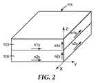
図2は、第2材料115の第2層上に配置された(例えば、共押出により)第1材料113の第1層を包含する多層光学フィルム111を図解している。第1材料及び第2材料のいずれか又は両方が、複屈折であってもよい。2つの層だけが図2に図解され、本明細書において一般に記載されているが、該プロセスは、いずれの数の異なる材料から作製される数百若しくは数千まであるいはそれ以上の層を有する多層光学フィルムに適用でき、例えば第1材料113の複数の第1層及び第2材料115の複数の第2層を有する多層光学フィルムに適用できる。多層光学フィルム111又は光学フィルム101は、追加の層を包含してもよい。追加の層は、光学的、例えば、追加の光学機能を発揮するものであってもよいし、又は非光学的、例えばそれらの機械的若しくは化学的特性、又は両方のために選択されてもよい。参照により本明細書に組み込まれる米国特許番号第6,179,948号で論じられているように、これらの追加の層は、本明細書に記載される加工条件下で延伸される場合があり、フィルムの全体的な光学及び/又は機械的特性に寄与する場合があるが、明瞭さ、及び平易化の目的でこれらの層は、この明細書では更に議論しない。 FIG. 2 illustrates a multilayer
光学フィルム111の材料は、粘弾性特性を有するように選択され、フィルム111内の2つの材料113及び115の延伸挙動を少なくとも部分的に切り離す。例えば、幾つかの代表的な実施形態では、伸張又は延伸に対して2つの材料113及び115の応答を切り離すことが有益である。延伸挙動を切り離すことにより、材料の屈折率の変化を別々に制御し、2つの異なる材料の延伸状態、したがって複屈折度の様々な組み合わせを得ることができる。このようなプロセスの1つでは、2つの異なる材料は、共押出多層光学フィルムなどの多層光学フィルムの光学層を形成する。キャストプロセス中の延伸が意図的に又は付随して押出フィルムに導入されることがあるとはいえ、層の屈折率は、最初の等方性を有する(即ち、屈折率は、各軸に沿って同じである)ことができる。 The material of the
反射型偏光子形成の1つのアプローチは、本開示による加工の結果として複屈折になる第1材料と、屈折率が実質的に等方性のままである、即ち延伸プロセス中に感知されるほどの複屈折量を発現しない第2材料とを使用する。幾つかの代表的な実施形態では、第2材料は、延伸後第1材料の延伸されていない面内屈折率に一致する屈折率を有するように選択される。 One approach to reflective polarizer formation is to have a first material that becomes birefringent as a result of processing according to the present disclosure and that the refractive index remains substantially isotropic, i.e. perceived during the stretching process. And a second material that does not express the amount of birefringence. In some exemplary embodiments, the second material is selected to have a refractive index that matches the unstretched in-plane refractive index of the first material after stretching.
図1、2の光学フィルムに使用するのに好適な材料は、例えば米国特許第5,882,774号で論じられており、これは本明細書に参考として組み込まれる。好適な材料としては、例えば、ポリエステル、コポリエステル及び変性コポリエステルなどのポリマーが挙げられる。この文脈では、用語「ポリマー」は、ホモポリマー及びコポリマー、並びに、例えば共押出、又は、例えばエステル交換などの反応によって、混和性ブレンドの形で形成されるポリマー又はコポリマーを包含すると考えられる。用語「ポリマー」及び「コポリマー」は、ランダム及びブロックコポリマーの両方を包含する。本開示によって構成される光学体における幾つかの代表的な光学フィルムに使用するのに好適なポリエステル類には、一般的にはカルボキシレート及びグリコールサブユニットが挙げられ、カルボキシレートモノマー分子とグリコールモノマー分子との反応によって生成され得る。各々のカルボキシレートモノマー分子は、2つ以上のカルボン酸又はエステル官能基を有し、各グリコールモノマー分子は、2つ以上のヒドロキシ官能基を有する。カルボキシレートモノマー分子はすべて同じでもよいし、2つ以上の種類の異なる分子でもよい。グリコールモノマー分子にも同じことが言える。炭酸のエステルによるグリコールモノマー分子の反作用に由来するポリカーボネートは、「ポリエステル」という用語の範囲内に含まれる。 Suitable materials for use in the optical films of FIGS. 1 and 2 are discussed, for example, in US Pat. No. 5,882,774, which is incorporated herein by reference. Suitable materials include, for example, polymers such as polyester, copolyester and modified copolyester. In this context, the term “polymer” is considered to encompass homopolymers and copolymers and polymers or copolymers formed in the form of miscible blends, for example by reaction such as coextrusion or transesterification. The terms “polymer” and “copolymer” encompass both random and block copolymers. Polyesters suitable for use in some representative optical films in optical bodies constructed in accordance with the present disclosure generally include carboxylate and glycol subunits, carboxylate monomer molecules and glycol monomers. It can be produced by reaction with molecules. Each carboxylate monomer molecule has two or more carboxylic acid or ester functional groups, and each glycol monomer molecule has two or more hydroxy functional groups. The carboxylate monomer molecules may all be the same or two or more types of different molecules. The same is true for glycol monomer molecules. Polycarbonates derived from the reaction of glycol monomer molecules with esters of carbonic acid are included within the term “polyester”.
ポリエステル層のカルボキシレートサブユニットを形成するのに使用する好適なカルボキシレートモノマー分子には、例えば、2,6−ナフタレンジカルボキシル酸及びその異性体;テレフタル酸;イソフタル酸;フタル酸;アゼライン酸;アジピン酸;セバシン酸;ノルボルネンジカルボン酸;ビシクロオクタンジカルボン酸;1,6−シクロヘキサンジカルボン酸及びその異性体;t−ブチルイソフタル酸、トリメリット酸;イソフタル酸スルホン酸ナトリウム;2,2’−ビフェニルジカルボン酸及びその異性体;及びメチル又はエチルエステル類のようなそれらの酸の低級アルキルエステル類が挙げられる。用語「低級アルキル」は、本文中ではC1〜C10の直鎖又は分枝状アルキル基を表す。 Suitable carboxylate monomer molecules used to form the carboxylate subunit of the polyester layer include, for example, 2,6-naphthalenedicarboxylic acid and its isomers; terephthalic acid; isophthalic acid; phthalic acid; Adipic acid; sebacic acid; norbornene dicarboxylic acid; bicyclooctane dicarboxylic acid; 1,6-cyclohexanedicarboxylic acid and its isomers; t-butylisophthalic acid, trimellitic acid; sodium isophthalic acid sulfonate; Acids and isomers thereof; and lower alkyl esters of these acids such as methyl or ethyl esters. The term “lower alkyl” refers herein to a C1-C10 linear or branched alkyl group.
ポリエステル層のグリコールサブユニットを形成するのに用いられる適切なグリコールモノマー分子は、エチレングリコール、プロピレン・グリコール、1,4−ブタンジオール及びその異性体、1,6−ヘキサンジオール、ネオペンチル・グリコール、ポリエチレングリコール、ジエチレングリコール、トリシクロデカンジオール、1,4−シクロヘキサンジメタノール及びその異性体、ノルボルナンジオール、ビシクロ−オクタンジオール、トリメチロールプロパン、ペンタエリスリトール、1,4−ベンゼンジメタノール及びその異性体、ビスフェノールA、1,8−ジヒドロキシ・ビフェニル及びその異性体、及び、1,3−ビス(2−ヒドロキシエトキシ)ベンゼンを包含する。 Suitable glycol monomer molecules used to form the glycol subunit of the polyester layer are ethylene glycol, propylene glycol, 1,4-butanediol and its isomers, 1,6-hexanediol, neopentyl glycol, polyethylene Glycol, diethylene glycol, tricyclodecanediol, 1,4-cyclohexanedimethanol and its isomers, norbornanediol, bicyclo-octanediol, trimethylolpropane, pentaerythritol, 1,4-benzenedimethanol and its isomers, bisphenol A 1,8-dihydroxy biphenyl and its isomers, and 1,3-bis (2-hydroxyethoxy) benzene.
本開示の光学フィルムに有用な代表的なポリマーは、例えば、ナフタレンジカルボン酸とエチレングリコールとの反応によって作製することができるポリエチレンナフタレン酸(PEN)である。ポリエチレン2,6−ナフタレン酸(PEN)は、しばしば第1ポリマーとして選択される。PENは大きな正の応力光係数を有し、伸張後に効果的に複屈折を保持し、可視領域の範囲内でほとんど又は全く吸光度を有さない。PENはまた等方性状態の大きな屈折率を有する。偏光平面が伸張方向と平行になる時、550nm波長の偏光入射光線におけるその屈折率は約1.64から約1.9もの高さまで増加する。分子の延伸の増加によって、PENの複屈折が増加する。分子の延伸は、他の伸張状態を固定したまま材料をより大きな伸張割合まで伸張することにより増加し得る。第1ポリマーとして好適な他の半結晶性ポリエステルには、例えば、ポリブチレン2,6−ナフタレン酸(PBN)、ポリエチレンテレフタラート(PET)、及びそれらのコポリマーが挙げられる。 A representative polymer useful for the optical films of the present disclosure is, for example, polyethylene naphthalene acid (PEN) that can be made by the reaction of naphthalene dicarboxylic acid and ethylene glycol. Polyethylene 2,6-naphthalene acid (PEN) is often selected as the first polymer. PEN has a large positive stress light coefficient, effectively retains birefringence after stretching, and has little or no absorbance within the visible region. PEN also has a large refractive index in the isotropic state. When the plane of polarization is parallel to the stretching direction, its refractive index for a 550 nm wavelength polarized incident light increases from about 1.64 to as high as about 1.9. The increase in molecular stretching increases the birefringence of PEN. The stretching of the molecule can be increased by stretching the material to a larger stretch rate while keeping other stretch states fixed. Other semi-crystalline polyesters suitable as the first polymer include, for example, polybutylene 2,6-naphthalene acid (PBN), polyethylene terephthalate (PET), and copolymers thereof.
幾つかの代表的な実施形態では、第2光学層の第2ポリマーは、完成したフィルムにおいて少なくとも1つの方向の屈折率が同じ方向の第1ポリマーの屈折率と有意に異なるように選択されるべきである。つまり、ポリマー材料は典型的には分散性であって、屈折率は波長に応じて変化するので、これらの条件は問題となる特定のスペクトル帯域幅によって判断されるべきである。これまでの議論によって、第2ポリマーの選択は、問題の多層光学フィルムの用途の指定だけでなく、第1ポリマーの選択並びに処理条件に依存することが理解できよう。 In some exemplary embodiments, the second polymer of the second optical layer is selected such that in the finished film, the refractive index in at least one direction is significantly different from the refractive index of the first polymer in the same direction. Should. That is, since polymer materials are typically dispersive and the refractive index varies with wavelength, these conditions should be judged by the particular spectral bandwidth in question. From the discussion so far, it will be appreciated that the choice of the second polymer depends not only on the application specification of the multilayer optical film in question, but also on the choice of the first polymer as well as the processing conditions.
光学フィルム、特に第1光学層の第1ポリマーに使用されて好適な他の材料が、例えば、米国特許番号第6,352,762号、米国特許番号第6,498,683号、米国特許出願通し番号第09/229724号、米国特許出願通し番号第09/232332号、米国特許出願通し番号第09/399531号及び米国特許出願通し番号第09/444756号に記載されており、参照により本明細書に組み込まれる。第1ポリマーとして有用な他のポリエステルは、90mol%のジメチルナフタレン酸ジカルボキシレート及び10mol%のジメチルテレフタラート由来のカルボキシレートサブユニット、及び100mol%のエチレングリコールサブユニット由来のグリコールサブユニットを有し固有粘度(IV)が0.48dL/gのcoPENである。このポリマーの屈折率はおよそ1.63である。本明細書中でこのポリマーは、低融点PEN(90/10)と称される。他の有用な第1ポリマーは、イーストマンケミカル社(Eastman Chemical Company)(テネシー州キングスポート(Kingsport))から入手可能な0.74dL/gの固有粘度を有するPETである。非ポリエステルポリマーも偏光フィルムを作製するのに有用である。例えば、ポリエーテルイミドをPEN及びcoPENなどのポリエステルと共に用いて、多層反射鏡を生成させることができる。ポリエチレンテレフタレートとポリエチレン(例えば、エンゲージ(Engage)8200の製品名でミシガン州ミッドランドのダウケミカル社(Dow Chemical Corp.)から市販されているもの)など、その他のポリエステル/ポリエステル以外の物質の組み合わせを用いることができる。 Other materials suitable for use in optical films, particularly the first polymer of the first optical layer, are described in, for example, US Pat. No. 6,352,762, US Pat. No. 6,498,683, US Patent Application. Serial No. 09/229724, U.S. Patent Application Serial No. 09/232332, U.S. Patent Application Serial No. 09/399531, and U.S. Patent Application Serial No. 09/444756, which are incorporated herein by reference. . Other polyesters useful as the first polymer have 90 mol% dimethyl naphthalene dicarboxylate and 10 mol% dimethyl terephthalate derived carboxylate subunits and 100 mol% ethylene glycol subunit derived glycol subunits. It is coPEN having an intrinsic viscosity (IV) of 0.48 dL / g. The refractive index of this polymer is approximately 1.63. This polymer is referred to herein as low melting point PEN (90/10). Another useful first polymer is PET having an intrinsic viscosity of 0.74 dL / g, available from Eastman Chemical Company (Kingsport, TN). Non-polyester polymers are also useful for making polarizing films. For example, polyetherimide can be used with polyesters such as PEN and coPEN to produce a multilayer reflector. Use other polyester / non-polyester combinations such as polyethylene terephthalate and polyethylene (for example, commercially available from Dow Chemical Corp., Midland, Mich. Under the product name Engage 8200) be able to.
第2光学層は、第1ポリマーのそれに適合するガラス転移温度を有し、第1ポリマーの等方性屈折率と類似の屈折率を有する多様なポリマーから作製することができる。光学フィルム、特に第2光学層で使用するのに好適な他のポリマーの例としては、上述のCoPEN以外に、ビニルナフタレン、スチレン、無水マレイン酸、アクリレート及びメタクリレートのようなモノマーから作製されるビニルポリマー及びコポリマーが挙げられる。そのようなポリマーの例には、ポリ(メチルメタクリレート)(PMMA)などのポリアクリレート、ポリメタクリレート、及びアイソタクチックポリスチレン又はシンジオタクチックポリスチレンが挙げられる。他のポリマーには、ポリスルホン、ポリアミド、ポリウレタン、ポリアミン酸、及びポリイミドなどの縮合ポリマーが挙げられる。更には、第2光学層は、ポリエステル及びポリカーボネートのようなポリマー及びコポリマーから形成させることができる。 The second optical layer can be made from a variety of polymers having a glass transition temperature compatible with that of the first polymer and having a refractive index similar to the isotropic refractive index of the first polymer. Examples of other polymers suitable for use in the optical film, particularly the second optical layer, include vinyl made from monomers such as vinyl naphthalene, styrene, maleic anhydride, acrylate and methacrylate, in addition to the above-mentioned CoPEN. Polymers and copolymers are mentioned. Examples of such polymers include polyacrylates such as poly (methyl methacrylate) (PMMA), polymethacrylate, and isotactic or syndiotactic polystyrene. Other polymers include condensation polymers such as polysulfone, polyamide, polyurethane, polyamic acid, and polyimide. Further, the second optical layer can be formed from polymers and copolymers such as polyester and polycarbonate.
その他の代表的な好適な、とりわけ第2光学層での使用に好適なポリマーとしては、デラウェア州ウィルミントンのイネオスアクリリクス社(Ineos Acrylics, Inc.)からCP71及びCP80の製品名で市販されているようなポリメチルメタクリレート(PMMA)、又は、PMMAよりもガラス転移温度の低いポリエチルメタクリレート(PEMA)のホモポリマーが挙げられる。追加の第2ポリマーとしては、75重量%のメチルメタクリレート(MMA)モノマー及び25重量%のエチルアクリレート(EA)モノマーから作られているcoPMMA(イネオスアクリリクス社(Ineos Acrylics, Inc.)からパースペックス(Perspex)CP63の製品名で市販されている)、MMAコモノマーユニット及びn−ブチルメタクリレート(nBMA)コモノマーユニットによって形成されているcoPMMA、又は、PMMAと、テキサス州ヒューストンのソルベーポリマーズ社(Solvay Polymers, Inc.)からソレフ(Solef)1008の製品名で市販されているようなポリ(フッ化ビニリデン)(PVDF)のブレンドといったPMMA(coPMMA)のコポリマーが挙げられる。 Other representative suitable polymers, particularly suitable for use in the second optical layer, are commercially available under the product names CP71 and CP80 from Ineos Acrylics, Inc. of Wilmington, Delaware. And polymethyl methacrylate (PMMA) or a homopolymer of polyethyl methacrylate (PMMA) having a glass transition temperature lower than that of PMMA. An additional second polymer is coPMMA (Ineos Acrylics, Inc.) made from 75% by weight methyl methacrylate (MMA) monomer and 25% by weight ethyl acrylate (EA) monomer. CoPMMA or PMMA formed by the MMA comonomer unit and n-butyl methacrylate (nBMA) comonomer unit (commercially available under the product name Perspex CP63) and Solvay Polymers of Houston, Texas PMMA (coPMMA) copolymers, such as blends of poly (vinylidene fluoride) (PVDF), such as that commercially available under the product name Solef 1008.
更に、特に第2層に使用する他の好適なポリマーには、例えばダウ・デュポンエラストマーズ(Dow-Dupont Elastomers)から商標表記エンゲージ(Engage)8200として入手可能なポリ(エチレン−co−オクテン)(PE−PO)のようなポリオレフィンコポリマー、テキサス州ダラス(Dallas)のフィナオイルアンドケミカル社(Fina Oil and Chemical Co)から商標表記Z9470として入手可能なポリ(プロピレン−co−エチレン)(PPPE)、及びユタ州ソルトレイクシティ(Salt Lake City)のハンツマンケミカル社(Huntsman Chemical Corp)から商標表記レックスフレックス(Rexflex)W111として入手可能なアタクチックポリプロピレン(aPP)及びイソタクチックポリプロピレン(iPP)のコポリマーが挙げられる。光学フィルムには更に、例えば、第2光学層に、デラウェア州ウィルミントンのE.I.デュポンデュヌムール社(E.I. duPont de Nemours & Co., Inc.)からバイネル(Bynel)4105の製品名で市販されているような線状低密度ポリエチレン−g−無水マレイン酸(LLEPE−g−MA)などの官能化ポリオレフィンを搭載することもできる。 In addition, other suitable polymers, particularly for use in the second layer, include, for example, poly (ethylene-co-octene) (available from Dow-Dupont Elastomers under the trademark Engage 8200). A polyolefin copolymer such as PE-PO), poly (propylene-co-ethylene) (PPPE) available under the trade designation Z9470 from Fina Oil and Chemical Co. of Dallas, Texas, and Mention may be made of copolymers of atactic polypropylene (aPP) and isotactic polypropylene (iPP) available under the trade designation Rexflex W111 from Huntsman Chemical Corp of Salt Lake City, Utah. It is done. The optical film may further include, for example, E.I., Wilmington, Del., On the second optical layer. I. Linear low density polyethylene-g-maleic anhydride (LLEPE-g-MA) as marketed by EI duPont de Nemours & Co., Inc. under the product name Bynel 4105 Functionalized polyolefins such as can also be mounted.
偏光子の場合の材料の代表的な組み合わせとしては、PEN/co−PEN、ポリエチレンテレフタレート(PET)/co−PEN、PEN/sPS、PEN/イースター(Eastar)、及び、PET/イースター(Eastar)が挙げられるが、ここで「co−PEN」はナフタレンジカルボン酸(既述済み)系のコポリマー又はブレンドを意味しており、イースター(Eastar)は、イーストマンケミカル社(Eastman Chemical Co.)から市販されているポリシクロヘキサンジメチレンテレフタレートである。ミラーの場合の材料の代表的な組み合わせとしては、PET/coPMMA、PEN/PMMA又はPEN/coPMMA、PET/ECDEL、PEN/ECDEL、PEN/sPS、PEN/THV、PEN/co−PET、PET/co−PET及びPET/sPSが挙げられ、ここで「co−PET」は、テレフタル酸(既述済み)に基づくコポリマー又はブレンドを指し、ECDELは、イーストマンケミカル社(Eastman Chemical Co.)から市販されている熱可塑性ポリエステルであり、THVは、3M社(3M Company)から市販されているフルオロポリマーである。PMMAはポリメチルメタクリレートを表し、PETGは第2グリコール(通常はシクロヘキサンジメタノール)に用いるPETのコポリマーを表す。sPSは、シンジオタクチックポリスチレンを指す。 Typical combinations of materials in the case of polarizers include PEN / co-PEN, polyethylene terephthalate (PET) / co-PEN, PEN / sPS, PEN / Easter (Eastar), and PET / Easter (Eastar). Where “co-PEN” means a copolymer or blend of naphthalene dicarboxylic acid (as previously described) system, and Easter is commercially available from Eastman Chemical Co. Polycyclohexanedimethylene terephthalate. Representative combinations of materials in the case of mirrors include PET / coPMMA, PEN / PMMA or PEN / coPMMA, PET / ECDEL, PEN / ECDEL, PEN / sPS, PEN / THV, PEN / co-PET, PET / co -PET and PET / sPS, where "co-PET" refers to a copolymer or blend based on terephthalic acid (as previously described) and ECDEL is commercially available from Eastman Chemical Co. THV is a fluoropolymer commercially available from 3M Company. PMMA represents polymethyl methacrylate and PETG represents a copolymer of PET used for the second glycol (usually cyclohexanedimethanol). sPS refers to syndiotactic polystyrene.
他の実施形態では、光学フィルムは、ブレンド光学フィルムであることができ、又はそれを包含することができる。幾つかの代表的な実施形態では、ブレンド光学フィルムは、拡散反射型偏光子であってもよい。本開示による典型的なブレンドフィルムでは、少なくとも2つの異なる材料のブレンド(又は混合物)が使用される。特定の軸に沿った2つ又はそれ以上の材料の屈折率の不整合が使用され、その軸に沿って偏光される入射光線を実質的に散乱させ、その光線の有意な量の拡散反射をもたらすことができる。2つ又はそれ以上の材料の屈折率が整合される軸の方向に偏光される入射光線は、実質的に透過され又は少なくともずっと少ない程度の散乱のみを伴って透過されることになる。材料の相対屈折率など、光学フィルムの他の特性を制御することにより、拡散反射型偏光子が構成され得る。このようなブレンドフィルムは、多くの異なる形態を取ることができる。例えば、ブレンド光学フィルムは、1つ以上の共連続相、1つ以上の連続相内の1つ以上の分散相、又は共連続相を包含してもよい。様々なブレンドフィルムの一般的な形成及び光学特性が、米国特許番号第5,825,543号及び米国特許番号第6,111,696号で更に論じられており、その開示が、参照により本明細書に組み込まれる。 In other embodiments, the optical film can be or include a blended optical film. In some exemplary embodiments, the blended optical film may be a diffuse reflective polarizer. In a typical blend film according to the present disclosure, a blend (or mixture) of at least two different materials is used. An index mismatch of two or more materials along a particular axis is used to substantially scatter incident light polarized along that axis, resulting in a significant amount of diffuse reflection of that light. Can bring. Incident light that is polarized in the direction of the axis where the refractive indices of the two or more materials are matched will be substantially transmitted or at least transmitted with much less scattering. By controlling other properties of the optical film, such as the relative refractive index of the material, a diffuse reflective polarizer can be constructed. Such blended films can take many different forms. For example, a blended optical film may include one or more co-continuous phases, one or more dispersed phases within one or more continuous phases, or a co-continuous phase. The general formation and optical properties of various blend films are further discussed in US Pat. No. 5,825,543 and US Pat. No. 6,111,696, the disclosures of which are hereby incorporated by reference. Embedded in the book.
図3は、第1材料と、第1材料に実質的に不混和性である第2材料とのブレンドから形成される本開示の実施形態を図解している。図3では、光学フィルム201は、連続(マトリックス)相203と分散(不連続)相207から形成される。連続相は、第1材料を含んでもよく、第2相は、第2材料を含んでもよい。フィルムの光学特性を使用し、拡散反射型偏光フィルムを形成してもよい。このようなフィルムでは、連続及び分散相材料の屈折率は、1つの面内軸に沿って実質的には同じになり、別の面内軸に沿って実質的には異なる。一般に、材料の一方又は両方が、適切な条件下での伸張又は延伸の結果、面内複屈折を発現することができる。図3に示したものなどの拡散反射型偏光子では、フィルムの1つの面内軸の方向の材料の屈折率をできるだけ緊密に整合させ、同時に他の面内軸の方向にはできるだけ大きい屈折率の不整合を有するようにすることが望ましい。 FIG. 3 illustrates an embodiment of the present disclosure formed from a blend of a first material and a second material that is substantially immiscible with the first material. In FIG. 3, the
光学フィルムが、図3に示すような分散相と連続相とを包含するブレンドフィルム、又は第1共連続相と第2共連続相とを包含するブレンドフィルムである場合、多くの異なる材料が、連続相又は分散相として使用されてもよい。このような材料としては、シリカ系ポリマーなどの無機材料、液晶などの有機材料並びにモノマー、コポリマー、グラフトポリマー及びこれらの混合物又はブレンドを含むポリマー材料が挙げられる。拡散反射型偏光子の特性を有するブレンド光学フィルムの連続及び分散相又は共連続相として使用されるように選択された材料は、幾つかの代表的な実施形態では、面内複屈折を導入するため第2セットの加工条件下で延伸可能な少なくとも1つの光学材料及び第2セットの加工条件下で感知されるほどに延伸せず、感知されるほどの量の複屈折を発現しない少なくとも1つの材料を包含してもよい。 If the optical film is a blend film comprising a dispersed phase and a continuous phase as shown in FIG. 3, or a blend film comprising a first co-continuous phase and a second co-continuous phase, many different materials are It may be used as a continuous phase or a dispersed phase. Such materials include inorganic materials such as silica-based polymers, organic materials such as liquid crystals, and polymeric materials including monomers, copolymers, graft polymers, and mixtures or blends thereof. Materials selected to be used as continuous and disperse or co-continuous phases of blended optical films having the properties of diffusely reflecting polarizers introduce in-plane birefringence in some exemplary embodiments Therefore, at least one optical material that is stretchable under the second set of processing conditions and at least one that does not stretch appreciably under the second set of process conditions and does not develop a perceptible amount of birefringence Materials may be included.
ブレンドフィルムの材料選択に関する詳細が、米国特許第5,825,543号及び米国特許第6,590,705号に詳述されており、その両方が参照により組み込まれる。 Details regarding blend film material selection are detailed in US Pat. No. 5,825,543 and US Pat. No. 6,590,705, both of which are incorporated by reference.
連続相に好適な材料(特定の構造物における分散相又は共連続相に使用されてもよい)は、イソフタル酸、アゼライン酸、アジピン酸、セバシン酸、ジ安息香酸(dibenzoic)、テレフタル酸、2,7−ナフタレンジカルボン酸、2,6−ナフタレンジカルボン酸、シクロヘキサンジカルボン酸及びビ安息香酸(bibenzoic)(4,4’−ビ安息香酸を包含する)などのカルボン酸に基づくモノマーから作製される材料又は前述の酸の対応するエステル(即ち、テレフタル酸ジメチル)から作製される材料を包含する非晶質、半結晶質又は結晶性ポリマー材料であってもよい。これらのうち、2,6−ポリエチレンナフタレート(PEN)、PENとポリエチレンテレフタレート(PET)のコポリマー、PET、ポリプロピレンテレフタレート、ポリプロピレンナフタレート、ポリブチレンテレフタレート、ポリブチレンナフタレート、ポリヘキサメチレンテレフタレート、ポリヘキサメチレンナフタレート及びその他の結晶性ナフタレンジカルボン酸ポリエステルが好ましい。PEN及びPET並びに中間体組成物のコポリマーが、それらのひずみ誘起複屈折及び伸張後恒久的に複屈折を残すそれらの性能のため特に好ましい。 Suitable materials for the continuous phase (which may be used for the dispersed or co-continuous phase in certain structures) are isophthalic acid, azelaic acid, adipic acid, sebacic acid, dibenzoic acid, terephthalic acid, 2 Materials made from monomers based on carboxylic acids such as 1,7-naphthalenedicarboxylic acid, 2,6-naphthalenedicarboxylic acid, cyclohexanedicarboxylic acid and bibenzoic (including 4,4'-bibenzoic acid) Or it may be an amorphous, semi-crystalline or crystalline polymeric material including materials made from the corresponding esters of the aforementioned acids (ie, dimethyl terephthalate). Among these, 2,6-polyethylene naphthalate (PEN), copolymer of PEN and polyethylene terephthalate (PET), PET, polypropylene terephthalate, polypropylene naphthalate, polybutylene terephthalate, polybutylene naphthalate, polyhexamethylene terephthalate, polyhexa Methylene naphthalate and other crystalline naphthalene dicarboxylic acid polyesters are preferred. Copolymers of PEN and PET and intermediate compositions are particularly preferred due to their strain-induced birefringence and their ability to leave birefringence permanently after stretching.
幾つかのフィルム構造物の第2ポリマーに好適な材料としては、第1ポリマー材料中に適切なレベルの複屈折を生成するために使用される条件下で延伸される時に等方性又は複屈折である材料が挙げられる。好適な例としては、ポリカーボネート(PC)及びコポリカーボネート、ポリスチレン−ポリメチルメタクリレートコポリマー(PS−PMMA)、例えば、商標表記MS 600(50%アクリレート含有量)NAS 21(20%アクリレート含有量)としてペンシルベニア州ムーンタウンシップ(Moon Township)のノバケミカル(Nova Chemical)から入手可能なものなどのPS−PMMA−アクリレートコポリマー、例えば、商標表記DYLARKとしてノバケミカル(Nova Chemical)から入手可能なものなどのポリスチレン無水マレイン酸コポリマー、アクリロニトリル・ブタジエン・スチレン(ABS)及びABS−PMMA、ポリウレタン、ポリアミド、特にナイロン6、ナイロン6,6及びナイロン6,10などの脂肪族ポリアミド、ミシガン州ミッドランド(Midland)のダウケミカルから入手可能なTYRILなどのスチレン−アクリロニトリルポリマー(SAN)、及び例えば、バイエルプラスチックス(Bayer Plastics)から商標表記マクロブレンド(Makroblend)として入手可能なポリエステル/ポリカーボネートアロイ、GEプラスチックス(GE Plastics)から商標表記キシレックス(Xylex)として入手可能なもの、イーストマンケミカル(Eastman Chemical)から商標表記SA 100及びSA 115として入手可能なものなどのポリカーボネート/ポリエステルブレンド樹脂、例えばCoPET及びCoPENを含む脂肪族コポリエステル類などのポリエステル、ポリ塩化ビニル(PVC)並びにポリクロロプレンが挙げられる。 Suitable materials for the second polymer of some film structures include isotropic or birefringence when stretched under conditions used to produce an appropriate level of birefringence in the first polymer material. The material which is is mentioned. Suitable examples include polycarbonate (PC) and copolycarbonate, polystyrene-polymethyl methacrylate copolymer (PS-PMMA), for example, Pennsylvania under the trade designation MS 600 (50% acrylate content) NAS 21 (20% acrylate content). PS-PMMA-acrylate copolymers such as those available from Nova Chemical, Moon Township, for example, polystyrene anhydrides such as those available from Nova Chemical under the trade designation DYLARK Maleic acid copolymers, acrylonitrile butadiene styrene (ABS) and ABS-PMMA, polyurethanes, polyamides, especially aliphatic polyamides such as
1つの態様では、本開示は、例えば光学ディスプレイに有用な拡幅の延伸された光学フィルムのロールを作製する方法を対象としており、そこでは延伸された光学フィルムの有効な延伸軸は、一般にロールの長さにそろえられる。反射型偏光フィルムなどのこのフィルムのロールは、ロールの長さに沿ったブロック状態軸を有する吸収型偏光フィルムなどの他の光学フィルムのロールに容易にラミネートされてもよい。1つの代表的なロールは、MDに沿った有効な延伸軸を特徴とする複屈折材料を含む延伸された光学フィルムを包含し、TDに沿って偏光された光の屈折率とNDに沿って偏光された光の屈折率との間の正規化された差が、0.06未満である。 In one aspect, the present disclosure is directed to a method of making a widened stretched optical film roll useful, for example, in an optical display, wherein the effective stretch axis of the stretched optical film is generally that of the roll. Aligned to length. A roll of this film, such as a reflective polarizing film, may be easily laminated to a roll of other optical film, such as an absorbing polarizing film having a block state axis along the length of the roll. One exemplary roll includes a stretched optical film comprising a birefringent material characterized by an effective stretch axis along the MD, along the refractive index of light polarized along TD and along ND. The normalized difference between the refractive indices of the polarized light is less than 0.06.
本開示の代表的な方法は、少なくとも1つのポリマー材料、好ましくは少なくとも第1ポリマー材料及び第2ポリマー材料から作製される光学フィルムをもたらす工程を包含し、ポリマー材料の少なくとも1つは複屈折を発現することができる。光学フィルムは、本明細書では押し並べて第1延伸工程と呼ばれる第1の工程でクロスウェブ(TD)方向に伸張又は延伸され、たとえあるとしても低面内複屈折だけがフィルム内に発現されるように第1セットの加工条件下でフィルムを拡幅する。 Exemplary methods of the present disclosure include providing an optical film made from at least one polymeric material, preferably at least a first polymeric material and a second polymeric material, wherein at least one of the polymeric materials exhibits birefringence. Can be expressed. The optical film is stretched or stretched in the crossweb (TD) direction in a first step, referred to herein as the first stretch step, and only if any low in-plane birefringence is manifested in the film. Thus, the film is widened under the first set of processing conditions.
本明細書で使用する時、用語「拡幅する」とは、フィルム寸法が、ポリマー分子に実質的な分子延伸を導入することなしに好ましくは分子延伸がない状態で変更され、フィルムを構成する加工工程を指す。フィルムが第1加工工程で拡幅される場合、加工条件、例えば温度は、第1加工工程及び第2加工工程後フィルムが容認できないほど不均一にならず、光学フィルムの品質要件を満すことができるように選択されるべきである。 As used herein, the term “broadening” means that the film dimensions are changed without introducing substantial molecular stretching into the polymer molecules, preferably without molecular stretching, to form a film. Refers to a process. If the film is widened in the first processing step, the processing conditions, eg temperature, may not be unacceptably uneven after the first and second processing steps and meet the quality requirements of the optical film. Should be chosen as possible.
本明細書で使用する時、用語「延伸」とは、フィルム寸法が変更され、分子延伸がフィルムを構成するポリマー材料の1つ以上に引き起こされる加工工程を指す。本明細書では押し並べて第2延伸工程と呼ばれる第2加工工程では、フィルムは、第2セットの加工条件下でダウンウェブ(MD)方向に延伸され、所望の用途の光学フィルムに十分な複屈折を引き起こす。更に、追加の伸張又は延伸工程(複数)が、別々に又は第1延伸工程及び第2延伸工程と共に使用され、フィルムの光学特性(例えば、光学均一性、反り、剥離接着、複屈折及びその類)を改善できる。第2延伸工程の間に、フィルムは、クロスウェブ(TD)方向に沿って緩和される間に、ダウンウェブ(MD)方向に沿って延伸される。幾つかの代表的な実施形態では、第2延伸工程の間に、フィルムは、クロスウェブ(TD)方向に沿って、並びに垂直(厚さ)方向(ND)に沿って緩和される間に、ダウンウェブ(MD)方向に沿って延伸される。 As used herein, the term “stretching” refers to a processing step in which film dimensions are altered and molecular stretching is caused to one or more of the polymeric materials that make up the film. In the second processing step, referred to herein as the second stretching step, the film is stretched in the downweb (MD) direction under a second set of processing conditions, sufficient birefringence for the optical film of the desired application. cause. In addition, additional stretching or stretching steps can be used separately or in conjunction with the first and second stretching steps to provide optical properties of the film (eg, optical uniformity, warpage, peel adhesion, birefringence and the like). ) Can be improved. During the second stretching step, the film is stretched along the downweb (MD) direction while being relaxed along the crossweb (TD) direction. In some exemplary embodiments, during the second stretching step, the film is relaxed along the crossweb (TD) direction as well as along the vertical (thickness) direction (ND). Stretched along the downweb (MD) direction.
本開示により延伸された光学フィルムを作製する代表的なプロセスが、図4に概略的に示される。先ず、光学フィルムを装置300に供給し、フィルムをクロスウェブ(TD)方向若しくはダウンウェブ(MD)方向又は所望により両方に伸張させる。フィルムに適用される伸張工程は、逐次又は同時であってもよい。例えば、図4の装置は、チェーンの配列、又はフィルムウェブの縁部を把持する磁気駆動クリップ302を包含してもよい。個々のクリップは、コンピュータ制御され、フィルムウェブ304にそれが装置300を通って移動する時、各種の伸張プロファイルを提供するようにしてもよい。 An exemplary process for making a stretched optical film according to the present disclosure is schematically illustrated in FIG. First, an optical film is fed into the
図4に示されない代替的実施形態では、光学フィルム304は、可変ピッチスクリュー(varying-pitched screws)の配列により規定されるプロファイルで伸張されてもよい。スクリューは、MD伸張のプロファイルと相対量を制御し、TDプロファイルを制御するレールに沿って置かれ、他のプロセス条件と共同して伸張する。図4に示していない更に別の実施形態では、光学フィルム304は、機械パンタグラフ−レールシステムにより規定されるプロファイルで伸張されてもよく、機械パンタグラフ−レールシステムでは、MD伸張比を部分的に制御する個々のクリップの分離が、機械パンタグラフにより制御され、そこではTD伸張比は、クリップが移動するレール経路によって部分的に規定される。本開示によりフィルムを伸張するのに好適な幾つかの代表的な方法及び装置が、米国特許番号第3,150,433号(カンフ(Kampf))及び米国特許番号第4,853,602号(ホームズ(Hommes))に記載されており、両方が参照により本明細書に組み込まれる。装置300に供給されたフィルム304は、溶媒キャスト又は押し出しキャストフィルムであってもよい。図4に図解された実施形態では、フィルム304は、ダイ306から放出された押し出しフィルムであり、少なくとも1つ、好ましくは2つのポリマー材料を包含する。光学フィルム304は、予定された用途に依存して大きく変わることも可能で、図1に示したようなモノリシック構造、図2に示したような層状構造、若しくは図3に示したようなブレンド構造、又はこれらの組み合わせを有してもよい。 In an alternative embodiment not shown in FIG. 4, the
光学フィルム304に使用されるために選択される材料は、後続する延伸工程の前に好ましくはすべての望ましくない延伸をなくさなければならない。あるいは、第1延伸工程を支援するプロセスとしてキャスト又は押し出し工程中に意図的な延伸を引き起こすことができる。例えば、キャスト又は押し出し工程は、第1延伸工程の一部と考えられてもよい。フィルム304の材料は、光学フィルムの最終用途に基づき選択される、そしてそれは、すべての延伸工程後、面内複屈折を発現することになり、反射型偏光特性などの反射特性を有してもよい。本出願に詳細に記載された1つの代表的な実施形態では、フィルム304の材料に光学接続された材料が選択され、すべての延伸工程後、フィルムに反射型偏光子の特性を付与する。 The material selected for use in the
図4を更に参照すると、ひとたび光学フィルム304がダイ306から押し出され、ないしは別の方法で装置300に提供されると、光学フィルム304は、フィルム304の縁部を把持するクリップ302の適切な配置によりゾーン310内の第1延伸工程で伸張される。第1延伸工程は、第1セットの加工条件下(延伸温度、延伸速度及び延伸比の少なくとも1つ(例えばTD/MD延伸速度))で行われ、フィルム304は、クロスウェブ(TD)方向に幅が広くなる。第1セットの加工条件は、フィルムに引き起こされるいずれの追加の複屈折も低いように、即ち第1延伸工程でフィルム304のポリマー材料に引き起こされるのは微小以下の複屈折であるように、好ましくは複屈折が実質的にないように、最も好ましくは複屈折がないように選択されるべきである。幾つかの代表的な実施形態では、第1延伸工程後、面内複屈折は、約0.05未満、約0.03未満、より好ましくは約0.02未満、最も好ましくは約0.01未満である。 With further reference to FIG. 4, once the
所定のセットの加工条件下で延伸するポリマー材料の傾向は、ポリマーの粘弾性挙動の結果であり、一般にポリマー材料の分子緩和速度の結果である。分子緩和速度は、平均最長総緩和時間(即ち総分子再配列)又は同時間の分布を特徴とし得る。平均最長総緩和時間は、典型的に温度増加と共に増加し、ガラス転移温度近辺で非常に大きい値に接近する。平均最長総緩和時間は、ポリマー材料の結晶化及び/又は架橋により増加させることもできる、そしてそれは、実際上、典型的に使用される加工時間及び温度条件下でこの最長モードのすべての緩和を抑制する。分子量及び分布並びに化学的組成及び構造(例えば、分枝)が最長緩和時間に影響を及ぼすこともある。 The tendency of a polymer material to stretch under a given set of processing conditions is a result of the viscoelastic behavior of the polymer and is generally a result of the molecular relaxation rate of the polymer material. The molecular relaxation rate can be characterized by an average longest total relaxation time (ie total molecular rearrangement) or a simultaneous distribution. The average longest total relaxation time typically increases with increasing temperature and approaches a very large value near the glass transition temperature. The average longest total relaxation time can also be increased by crystallization and / or cross-linking of the polymer material, which in practice reduces all relaxation of this longest mode under the processing time and temperature conditions typically used. Suppress. Molecular weight and distribution as well as chemical composition and structure (eg, branching) can affect the longest relaxation time.
特定ポリマー材料の平均最長緩和時間が、およそプロセス延伸時間に等しいかそれ以上である場合、材料において実質的な分子延伸が延伸方向に発生することになる。したがって、高い及び低いひずみ速度が、それぞれ平均最長緩和時間未満又はそれを超える時間にわたり材料を延伸する工程に対応する。所定の材料の応答は、プロセスの延伸温度、延伸速度及び延伸比を制御することにより変更することができる。 If the average longest relaxation time of a particular polymeric material is approximately equal to or greater than the process stretching time, substantial molecular stretching will occur in the stretching direction in the material. Thus, high and low strain rates correspond to stretching the material for times less than or greater than the average longest relaxation time, respectively. The response of a given material can be altered by controlling the stretching temperature, stretching speed and stretch ratio of the process.
延伸プロセス中の延伸の程度は、広い範囲にわたって正確に制御することができる。特定の延伸プロセスでは、延伸プロセスによって、実際にフィルムの少なくとも1つの方向の分子延伸量を減少させることができる。延伸方向において、延伸プロセスにより引き起こされる分子の延伸は、実質的に延伸がない状態から僅かに光学的な延伸がある状態(例えばフィルムの光学特性に無視できる程度に僅かな影響をもたらす延伸)、更には後続のプロセス工程中に取り除くことができる様々な程度の光学的な延伸の範囲にわたる。 The degree of stretching during the stretching process can be accurately controlled over a wide range. In certain stretching processes, the stretching process can actually reduce the amount of molecular stretching in at least one direction of the film. In the stretching direction, the stretching of the molecule caused by the stretching process is from a state where there is substantially no stretching to a state where there is a slight optical stretching (for example, stretching that has a negligible effect on the optical properties of the film), Furthermore, it covers a range of optical stretching that can be removed during subsequent process steps.
光学的な延伸の相対強度は、フィルムの材料と相対屈折率に依存する。例えば、強い光学的な延伸は、所定の材料の全固有(標準化された)複屈折に関係し得る。また、所定の延伸プロセス順序において、延伸強度が材料間に実現可能な標準化屈折率差の総量に関係することもあり得る。分子の延伸のある規定量が、1つの文脈においては強い光学的な延伸と考えられ、別の文脈においては弱い又は非光学的な延伸と考えられる場合があることもいうまでもない。例えば、第1面内軸と平面外軸間の特定の複屈折量は、第2面内軸と平面外軸間の非常に大きい複屈折との関連で見る時、低いと考えられる場合がある。十分に短い時間及び/又は十分に低い温度で行われ、本開示の光学フィルムに包含される少なくとも1つの材料に幾らかの又は相当量の光学的な分子の延伸を引き起こすプロセスは、それぞれ弱い又は強い光学的に延伸した延伸プロセスである。長い時間及び/又は十分に高い温度にわたって行われ、ほとんど又は全く分子の延伸が発生しないようなプロセスは、それぞれ弱い又は実質的に非光学的な延伸プロセスである。 The relative strength of optical stretching depends on the film material and the relative refractive index. For example, strong optical stretching can be related to the total intrinsic (standardized) birefringence of a given material. Also, in a given stretching process sequence, the stretching strength can be related to the total amount of standardized refractive index difference that can be achieved between the materials. It goes without saying that a certain amount of molecular stretching may be considered strong optical stretching in one context and weak or non-optical stretching in another context. For example, the specific amount of birefringence between the first in-plane axis and the out-of-plane axis may be considered low when viewed in the context of the very large birefringence between the second in-plane axis and the out-of-plane axis. . Processes that occur at a sufficiently short time and / or at a sufficiently low temperature to cause stretching of some or a substantial amount of optical molecules in at least one material included in the optical film of the present disclosure are weak or It is a strong optically stretched drawing process. Processes that take place over a long period of time and / or sufficiently high temperature with little or no molecular stretching occurring are weak or substantially non-optical stretching processes, respectively.
プロセス条件に対する1つ以上の材料の延伸/不延伸応答を考慮して材料及びプロセス条件を選択することにより、たとえあるとしても各延伸工程の軸に沿った延伸量は、材料毎に別々に制御され得る。しかし、特定の延伸プロセスにより引き起こされる分子の延伸の量は、生じたフィルムの分子の延伸をそれ自体で必ずしも規定するものではない。第1延伸プロセスでの非光学的な有効な延伸量は、第2若しくは後続する延伸工程の更なる分子の延伸を補償し又は補助するため、1つの材料に対して許容される。 By selecting materials and process conditions taking into account the stretch / non-stretch response of one or more materials to process conditions, the stretch amount along the axis of each stretching process, if any, is controlled separately for each material. Can be done. However, the amount of molecular stretching caused by a particular stretching process does not necessarily dictate by itself the molecular stretching of the resulting film. A non-optically effective amount of stretching in the first stretching process is allowed for one material to compensate or assist in further molecular stretching in the second or subsequent stretching step.
延伸プロセスは、第1の近似で材料の延伸される変化を画定するが、高密度化などの二次的なプロセス又は結晶化などの相転移も、延伸的な特性に影響を及ぼすことがある。極端な材料の相互作用(例えば、自己集合又は液晶遷移)の場合には、これらの影響の方が大きいこともあり得る。典型的な場合、例えば、ポリマー分子の主鎖が流れとそろえられる傾向がある延伸ポリマーは、ひずみ誘起結晶化などが延伸的な特性に二次的な影響だけを有する傾向になるような効果をもたらす。しかし、ひずみ誘起及び他の結晶化は、こうした延伸の強度に有意な影響を有する(例えば、弱い延伸性引き上げを強い延伸性引き上げに変えることがあり得る)。したがって、光学フィルム304に使用されるために選択される材料はいずれも、第1延伸工程に適用される第1セットの加工条件で急速な結晶化が可能なものであってはならず、材料の1つは、感知されるほど結晶化が可能ものであってはならない。その結果、幾つかの用途では、PEN及びPETのコポリマーなど、第1セットの加工条件下でPENより遅く結晶化するcoPENが好ましい場合がある。好適な一例は、PEN90%とPET10%のコポリマーであり、本明細書では低融点PEN(LmPEN)と呼ぶ。 The stretching process defines the stretched change of the material with a first approximation, but secondary processes such as densification or phase transitions such as crystallization can also affect the stretch properties. . In the case of extreme material interactions (eg self-assembly or liquid crystal transitions), these effects can be greater. In typical cases, for example, a stretched polymer that tends to align the main chain of polymer molecules with the flow will have an effect such that strain-induced crystallization tends to have only a secondary effect on the stretch properties. Bring. However, strain induction and other crystallizations have a significant effect on the strength of such stretch (eg, a weak stretch increase can be changed to a strong stretch increase). Accordingly, any material selected for use in the
第1延伸工程の第1セットの加工条件は、フィルム304を構成するポリマー又はポリマー類により大きく変わり得る。一般に、高温、低延伸比及び/又は低ひずみ速度で延伸される時、ポリマーは粘稠な液体のように流れ、分子延伸がほとんど又は全く存在しない傾向がある。低温及び/又は高ひずみ速度で、ポリマーは、付随的分子の延長によって、固体のように弾力的に延伸される傾向がある。低温プロセスは、典型的に非晶質ポリマー材料のガラス転移温度未満、好ましくは近辺であり、一方高温プロセスは、通常ガラス転移温度を超え、好ましくは相当程度超える。したがって、第1延伸工程は、典型的に高温(ガラス転移温度を超える)及び/又は低ひずみ速度で行われ、ほとんど又は全く分子的な延伸をもたらさないようにすべきである。本開示の典型的な実施形態では、第1延伸工程において、温度は、ポリマーが感知されるほど延伸しない十分な高さにすべきであるが光学フィルムの1つ以上のポリマーが静止結晶化するほど高くすべきではない。静止結晶化は、往々にして望ましくないと考えられている、というのは、それは、過度なヘイズなどの悪影響を及ぼす光学特性をもたらす場合があるからである。更に、フィルムが加熱される時間、即ち温度増加速度は、望ましくない延伸を避けるように調節すべきである。 The first set of processing conditions of the first stretching step can vary greatly depending on the polymer or polymers that make up the
例えば、高屈折率材料としてPENを有する、図2に示したような光学フィルムでは、第1延伸工程の温度範囲は、光学フィルムのポリマーの少なくとも1つのガラス転移温度より、時には光学フィルムのすべてのポリマーのガラス転移温度より約20℃〜約100℃高い。幾つかの代表的な実施形態では、第1延伸工程の温度範囲は、光学フィルムのポリマーの少なくとも1つ、往々にして光学フィルムのポリマーすべてのガラス転移温度より約20℃〜約40℃高い。 For example, in an optical film as shown in FIG. 2 having PEN as the high refractive index material, the temperature range of the first stretching step is sometimes at least one glass transition temperature of the polymer of the optical film, sometimes all of the optical film. About 20 ° C. to about 100 ° C. above the glass transition temperature of the polymer. In some exemplary embodiments, the temperature range of the first stretching step is from about 20 ° C. to about 40 ° C. above the glass transition temperature of at least one of the polymers of the optical film, often all of the polymers of the optical film.
第1加工条件が適用される第1延伸工程では、例えば、図4に示すゾーン310において、フィルム304は、好ましくはクロスウェブ(TD)方向に伸張又は延伸される。しかし、フィルム304は、所望によりクロスウェブ(TD)方向の伸張/延伸が発生すると同時にダウンウェブ(MD)方向にも伸張若しくは延伸されてもよく、即ちフィルムは、2軸的に伸張若しくは延伸されてもよく、又はフィルム304は、低面内複屈折、例えば僅かに面内複屈折する状態、好ましくは実質的に面内複屈折がない状態、より好ましくは面内複屈折がない状態だけがフィルム304のポリマー材料にもたらされる限り、TDに伸張後MD方向に伸張されてもよい。 In the first stretching step to which the first processing condition is applied, for example, in the
フィルム304に第1セットの加工条件を適用した後、多くの場合それに続いて、別の第2延伸工程において、第2セットの加工条件が図4に示すゾーン320のフィルムに適用される。ゾーン320の幾つかの代表的な具体的構成が以下に提供されるが、ゾーン320は、本開示の原則によって光学フィルム304が延伸されるいかなる他の好適な構成を有してもよい。第2延伸工程では、光学フィルム304はダウンウェブ(MD)方向に延伸され、その結果、複屈折がフィルムの少なくとも1つのポリマー材料に引き起こされ、第2延伸工程後少なくとも1つの複屈折材料の有効な延伸軸がMDに沿って配置される。光学フィルムが第1ポリマー材料及び第2ポリマー材料を包含する実施形態では、好ましくは第1面内軸(例えば、MD)に沿って第1材料と第2材料との間で屈折率不整合が引き起こされ、第1面内軸に対して直交している第2面内軸(例えば、TD)に沿っては第1材料と第2材料の間で、実質的に屈折率不整合は引き起こされない。幾つかの代表的な実施形態では、第1面内軸は、有効な延伸軸と一致する。 After applying the first set of processing conditions to the
幾つかの代表的な実施形態では、第2延伸工程中に伸張方向(MD)に沿ってもたらされる正規化された面内屈折率の差は、少なくとも約0.06、少なくとも約0.07、好ましくは少なくとも約0.09、より好ましくは少なくとも約0.11、更により好ましくは少なくとも約0.2である。少なくとも第1及び第2の異なるポリマー材料を包含する代表的な実施形態では、第2延伸工程後、MDに沿った第1材料及び第2材料の面内屈折率は、少なくとも約0.05のみ、好ましくは少なくとも約0.1のみ、より好ましくは少なくとも約0.15のみ、最も好ましくは少なくとも約0.2のみ異なってもよい。より一般的には、反射型偏光子の場合、光学フィルムの他の態様をできるだけ有意に劣化させない限りにおいて、できるだけ大きいMDに沿った屈折率不整合値を有することが望ましい。これらの特性は、以下に記載される第2延伸工程と同時に又はその後行われる追加の工程/プロセスにより改善することができる。 In some exemplary embodiments, the normalized in-plane refractive index difference provided along the direction of extension (MD) during the second stretching step is at least about 0.06, at least about 0.07, Preferably it is at least about 0.09, more preferably at least about 0.11, and even more preferably at least about 0.2. In an exemplary embodiment that includes at least a first and a second different polymeric material, after the second stretching step, the in-plane refractive indices of the first material and the second material along the MD are only at least about 0.05. Preferably at least about 0.1, more preferably at least about 0.15, and most preferably at least about 0.2. More generally, in the case of a reflective polarizer, it is desirable to have a refractive index mismatch value along the MD as large as possible, as long as other aspects of the optical film are not significantly degraded. These properties can be improved by additional steps / processes performed simultaneously with or after the second stretching step described below.
第2延伸工程後、例えば面内(TD)方向の整合した面内屈折率の間の正規化された屈折率の差が、たとえあるとしても、約0.06未満、より好ましくは約0.03未満、最も好ましくは約0.01未満であることが一般に望ましい。同様に、代表的な光学フィルムの厚さ方向、例えば、面外(ND)方向の屈折率の間のいずれかの正規化された差が、約0.11未満、約0.09未満、約0.06未満、より好ましくは約0.03未満、最も好ましくは約0.01未満であることが望ましい可能性がある。更に、少なくとも第1の異なるポリマー材料及び第2の異なるポリマー材料を包含する代表的な実施形態では、第2延伸工程後、TD、ND、又はTD及びNDに沿った第1材料の面内屈折率及び第2材料の面内屈折率は、約0.03未満、より好ましくは約0.02未満、最も好ましくは約0.01未満、異なってもよい。他の代表的な実施形態では、これらの条件は、第1延伸工程後及び第2延伸工程後又はいずれかの追加のプロセス工程後に満たされてもよい。 After the second stretching step, the normalized index difference, for example between the aligned in-plane indices in the in-plane (TD) direction, if any, is less than about 0.06, more preferably about 0.00. It is generally desirable to be less than 03, most preferably less than about 0.01. Similarly, any normalized difference between the refractive indices of typical optical films in the thickness direction, eg, out-of-plane (ND) direction, is less than about 0.11, less than about 0.09, about It may be desirable to be less than 0.06, more preferably less than about 0.03, and most preferably less than about 0.01. Further, in an exemplary embodiment that includes at least a first different polymeric material and a second different polymeric material, after the second stretching step, TD, ND, or in-plane refraction of the first material along TD and ND. The refractive index and the in-plane refractive index of the second material may vary by less than about 0.03, more preferably less than about 0.02, and most preferably less than about 0.01. In other exemplary embodiments, these conditions may be met after the first stretching step and after the second stretching step or after any additional process steps.
第2延伸工程では、代表的な光学フィルム304は、フィルムの第2面内軸(y又はクロスウェブ方向(TD))において並びに厚さ方向(z又は垂直方向(ND))に沿って、フィルムを収縮又は緩和させながら、フィルムの第1面内軸(x又は縦方向(MD))に沿って延伸される。これらの加工条件は、複屈折材料の屈折率が更に一軸性を得ることを可能にし、そのため、こうしたプロセスは、実質的に一軸の伸張又は延伸と呼ばれてもよい。それによって、本開示の方法は、MDに沿った有効な延伸軸を特徴とする複屈折材料を含む延伸された光学フィルムの製造を可能にし、及びTDに沿って偏光された光の屈折率とNDに沿って偏光された光の屈折率との間の正規化された差は、0.06未満である。 In the second stretching step, the exemplary
一般に、実質的に一軸の延伸プロセスは、フィルムを伸張することを包含し、それは縦方向(MD)、横方向(TD)、及び垂直方向(ND)に対応する3つの互いに直交する軸に関して記載され得る。これらの軸は、図5に図解されるように、フィルムの幅、長さ、及び厚さに対応する。実質的に一軸の伸張プロセスは、フィルムの領域32を、最初の構成34から最後の構成36に伸張する。縦方向(MD)は、フィルムが伸張デバイスをそれに沿って進む一般的な方向であり、横方向(TD)は、フィルムの平面内の第2軸であり、縦方向に直交している。垂直方向(ND)は、MD、TDの両方と直交しており、一般的には、ポリマーフィルムの厚さ寸法に対応している。 In general, a substantially uniaxial stretching process involves stretching a film, which is described with respect to three mutually orthogonal axes corresponding to the machine direction (MD), the cross direction (TD), and the vertical direction (ND). Can be done. These axes correspond to the width, length, and thickness of the film, as illustrated in FIG. The substantially uniaxial stretching process stretches the film region 32 from the initial configuration 34 to the final configuration 36. The machine direction (MD) is the general direction along which the film travels along the stretching device, and the transverse direction (TD) is the second axis in the plane of the film and is orthogonal to the machine direction. The vertical direction (ND) is orthogonal to both MD and TD and generally corresponds to the thickness dimension of the polymer film.
複屈折ポリマーの一軸延伸は、光学フィルム(又はフィルムの層)を提供し、その中で3つの直交する方向の内の2つの屈折率は実質的に同じである(例えば、図5に図解されるように、フィルムの幅(W)及び厚さ(T)方向)。第3の方向の(例えば、フィルムの長さ(L)方向に沿った)屈折率は、他の2つの方向の屈折率とは異なる。伸張変形は、延伸比のセット:縦方向延伸比(MDDR)、横方向延伸比(TDDR)、及び垂直方向延伸比(NDDR)として記載され得る。フィルム32に関して決定される時、特定の延伸比は一般に、所望の方向(例えばTD、MD、又はND)におけるフィルム32’の現在のサイズ(例えば長さ、幅、又は厚さ)と、その同じ方向におけるフィルム32の最初のサイズ(例えば長さ、幅、又は厚さ)との比として定義される。 Uniaxial stretching of the birefringent polymer provides an optical film (or layer of film) in which the two refractive indices in three orthogonal directions are substantially the same (eg, illustrated in FIG. 5). The width (W) and thickness (T) direction of the film). The refractive index in the third direction (eg, along the length (L) direction of the film) is different from the refractive index in the other two directions. Stretch deformation can be described as a set of stretch ratios: machine direction stretch ratio (MDDR), cross direction stretch ratio (TDDR), and vertical stretch ratio (NDDR). When determined with respect to film 32, the specific stretch ratio is generally the same as the current size (eg, length, width, or thickness) of film 32 ′ in the desired direction (eg, TD, MD, or ND). Defined as the ratio to the initial size (eg, length, width, or thickness) of film 32 in the direction.
横方向の寸法の増加を伴う完全な一軸伸張条件は、図5に図解されるように、それぞれ、λ、(λ)−1/2、及び(λ)−1/2のMDDR、TDDR、及びNDDRを結果として生じる(材料の一定密度を仮定する)。換言すれば、伸張中の均一密度を仮定すると、MDに沿って一軸に延伸されるフィルムは、伸張を通じてTDDR=(MDDR)−1/2となるものである。一軸性の程度に関する有用な指標Uは、以下のように定義することができる。Full uniaxial stretching conditions with increasing lateral dimensions are illustrated in FIG. 5 as follows: MDDR, TDDR of λ, (λ)−1/2 , and (λ)−1/2 , and NDDR results (assuming a constant density of material). In other words, assuming a uniform density during stretching, a film stretched uniaxially along MD is such that TDDR = (MDDR)−1/2 through stretching. A useful index U for the degree of uniaxiality can be defined as follows.

完全な一軸伸張については、Uは、伸張を通じて1である。Uが1未満の場合、伸張条件は「準一軸性」と見なされる。Uが1を超える場合は、伸張条件は「超一軸性」と見なされる。Uが1を超える状態は、様々なレベルの過緩和状態を表している。しかしながら、フィルムの密度が、ρfの要因により変化する場合、そこでは、ρf=ρ0/ρであり、ρは、伸張プロセス中の現時点での密度であり、及びρ0は、伸張開始時の最初の密度であり、そして予想されるように、NDDR=ρf/(TDDR*MDDR)である。予想されるように、Uは、密度の変化について補正され得、次の式によりUfを与える:For full uniaxial stretching, U is 1 through stretching. If U is less than 1, the stretching condition is considered “quasi-uniaxial”. If U is greater than 1, the stretching condition is considered “super uniaxial”. States where U is greater than 1 represent various levels of over-relaxation. However, if the density of the film is changed by factors [rhof, where aρ f = ρ 0 / ρ, ρ is the density at the present time during the stretching process, and [rho0 is the start extension The initial density of time and, as expected, NDDR = ρf / (TDDR* MDDR). As expected, U can be corrected for changes in density, giving Uf by the following equation:
典型的には、完全な一軸延伸が必要ではなく、最適条件からのある程度の偏位が、光学フィルムの最終用途を包含する多様な要因に依存して許容され得る。これに代わり、延伸中にわたって、又は、延伸の特定部分中に維持させるUの最小値若しくは閾値、又はUの平均値を定義することができる。例えば、Uの許容可能な最小値/閾値、又は平均値は、所望に応じて、又は特定の用途での必要性に応じて、0.7、0.75、0.8、0.85、0.9、又は0.95であり得る。 Typically, complete uniaxial stretching is not necessary and some deviation from the optimum can be tolerated depending on a variety of factors including the end use of the optical film. Alternatively, a minimum value or threshold value of U, or an average value of U, can be defined that is maintained during stretching or during a particular portion of stretching. For example, the acceptable minimum / threshold value, or average value of U is 0.7, 0.75, 0.8, 0.85, as desired or as needed for a particular application. It can be 0.9 or 0.95.
許容可能な、ほぼ一軸の用途の例として、液晶ディスプレイ用途に使用される反射型偏光子のオフ角特性は、TDが主要な一軸延伸方向である時、MDとNDとの屈折率の差により強く影響を受ける。0.08というMD及びNDの指数の差異は一部の用途では許容可能である。0.04という差異もその他の用途で許容することができる。より厳密な用途では、0.02以内という差異が好ましい。例えば、多くの場合、一軸横延伸フィルム用に、ポリエチレンナフタレート(PEN)又はPENのコポリマーが含まれているポリエステル系において、波長633nmで0.02以内というMD方向とND方向の屈折指数差を実現させるためには、0.85という一軸特性度で十分である。一部のポリエステル系、例えば、ポリエチレンテレフタレート(PET)では、実質的に一軸性ではない延伸フィルムの屈折指数の本質的差異が小さいため、0.80、更には0.75という更に低い値のUが許容可能と思われる。 As an example of an acceptable, nearly uniaxial application, the off-angle characteristics of reflective polarizers used in liquid crystal display applications are due to the difference in refractive index between MD and ND when TD is the primary uniaxial stretch direction. Strongly affected. A difference between the MD and ND indices of 0.08 is acceptable for some applications. A difference of 0.04 can be allowed for other applications. For stricter applications, a difference of 0.02 or less is preferred. For example, in many cases, in a polyester system containing polyethylene naphthalate (PEN) or a copolymer of PEN for a uniaxial transversely stretched film, a refractive index difference between the MD direction and the ND direction of 0.02 at a wavelength of 633 nm is obtained. To achieve this, a uniaxial characteristic of 0.85 is sufficient. In some polyester systems, such as polyethylene terephthalate (PET), the intrinsic difference in the refractive index of stretched films that are not substantially uniaxial is so small that U0 with a lower value of 0.80, or even 0.75. Seems to be acceptable.
準一軸延伸では、真の一軸特性の最後の値を用いて、以下の等式によりy(TD)方向とz(ND)方向との間を整合する屈折率のレベルを推定することができる。 In quasi-uniaxial stretching, the last value of true uniaxial characteristics can be used to estimate the level of refractive index that matches between the y (TD) and z (ND) directions by the following equation:
Δnyz=Δnyz(U=0)×(1−U)
ここで、Δnyzは、ある値UについてのTD方向(即ちy−方向)とND方向(即ちz−方向)の屈折率の間の差であり、及びΔnyz(U=0)は、TDDRが延伸を通じて一体に保たれる場合を除き、等しく延伸されるフィルムの屈折率の差である。この相関関係は、多様な光学フィルムで用いられているポリエステル系(PEN、PET、及び、PEN又はPETのコポリマーなど)については容易に予測可能であることが分かっている。これらのポリエステル系では、Δnyz(U=0)は典型的には、2つの面内方向TD(y−軸)とMD(x−軸)との間の屈折差である、差Δnxy(U=0)の約1/2以上である。Δnxy(U=0)の典型的な値は633nmにおいて最大約0.26である。Δnyz(U=0)の典型的な値は633nmにおいて最大0.15である。例えば、90/10coPEN、即ち、約90%のPEN様繰り返し単位及び10%のPET様繰り返し単位を含むコポリマーの典型的な最大伸長値は633nmで約0.14である。実際のフィルム延伸比によって測定した場合にUの値が0.75、0.88、及び0.97であり、対応するΔnyzの値が633nmにおいて0.02、0.01、及び0.003であるこの90/10coPENが含まれているフィルムを本発明の方法に従って作製した。Δnyz = Δnyz (U = 0) × (1-U)
Where Δnyz is the difference between the refractive indices in the TD direction (ie y-direction) and ND direction (ie z-direction) for a value U, and Δnyz (U = 0) is TDDR Is the difference in the refractive index of a film that is stretched equally, except where is held together through stretching. This correlation has been found to be readily predictable for polyester systems (such as PEN, PET, and copolymers of PEN or PET) used in a variety of optical films. In these polyester systems, Δnyz (U = 0) is typically the difference Δnxy (which is the refractive difference between the two in-plane directions TD (y-axis) and MD (x-axis). It is about 1/2 or more of U = 0). A typical value for Δnxy (U = 0) is a maximum of about 0.26 at 633 nm. A typical value for Δnyz (U = 0) is a maximum of 0.15 at 633 nm. For example, a typical maximum elongation value of 90/10 coPEN, ie, a copolymer comprising about 90% PEN-like repeat units and 10% PET-like repeat units is about 0.14 at 633 nm. The U values are 0.75, 0.88, and 0.97 as measured by the actual film stretch ratio, and the corresponding Δnyz values are 0.02, 0.01, and 0.003 at 633 nm. A film containing this 90/10 coPEN was prepared according to the method of the present invention.
様々な方法が、第2延伸工程中にゾーン320においてフィルムを延伸するために使用され得る。例えば図6は、例えば、偏光子のような光学体中の構成要素として使用するのに好適な多層光学フィルムなどの光学フィルムを実質的に一軸伸張するためのバッチ技術を図解している。平らな最初のフィルム24は、矢印26の方向に伸張されて伸張フィルム22を製造する。フィルム22は、フィルムの2つの縁部30が、伸張プロセス後にもはや平行でないように、ネックダウンしている。フィルムの中心部分28は、最も有用な光学特性を提供する。 Various methods can be used to stretch the film in
他の代表的な実施形態では、長さ延伸機(LO)がまた使用されて、実質的に一軸の延伸偏光フィルムを作製する場合がある。LOは、異なる速度のローラー間の少なくとも1つのスパンにわたって、縦方向(MD)にフィルムを長手方向に延伸し、その結果、このスパン又は延伸ギャップに沿って付与される縦方向延伸速度(MDDR)は、本質的に、最終段階のロールと開始段階のロールの速度の比である。フィルムは縁部の拘束なしにローラーに自由にかかるため、フィルムは、それが延伸する時に、横方向に沿って幅がネックダウンする可能性があり、並びにフィルムの平面に垂直な方向(ND又はz方向)に沿ってキャリパーを薄くする可能性がある。 In other exemplary embodiments, a length stretcher (LO) may also be used to make a substantially uniaxial stretched polarizing film. LO stretches the film in the machine direction (MD) longitudinally over at least one span between rollers of different speeds, so that the machine direction draw speed (MDDR) applied along this span or draw gap. Is essentially the ratio of the speed of the final stage roll to the initial stage roll. Because the film is free to rest on the rollers without edge constraints, the film can neck down along the transverse direction as it stretches, as well as in a direction perpendicular to the plane of the film (ND or There is a possibility that the caliper is made thin along the z direction.
図7Aは、LOを包含するフィルムラインの好適な実施形態の一部分を図解している。連続フィルム920は、ローラー912によって予備加熱ゾーンの中に運ばれてもよい。予備加熱ゾーンは、一揃いの加熱されたローラー913、放射加熱源914、予備加熱オーブン、又はこれらのいずれかの組み合わせを含んでもよい。予備加熱後、フィルム920は、それぞれが最初の遅いロール902と最後の速いロール906とを含む1つ以上の伸張ゾーンに運ばれる。それぞれが、延伸ギャップ940を通じた速いロール906の動作からのフィルムの引張りに抵抗するように、遅いロール902が典型的には駆動される。代表的な実施形態では、フィルム920は、延伸ギャップ940において更に加熱される。1つの典型的な加熱方法は、例えばIR加熱アセンブリ950及び/又は917によるなどの放射加熱である。 FIG. 7A illustrates a portion of a preferred embodiment of a film line that includes LO. The
代表的な実施形態では、ギャップ940にわたる延伸後、フィルム920は急冷される。典型的には、速いロール906は、フィルム920の急冷を少なくとも開始するように設定された冷却されたロールである。実際には、フィルム920は、速いロール906との接触の際に直ちに急冷されないが、その代わりに速いロール906の上で短い距離において更に延伸されることが見出される場合がある。1つの実施形態では、更なる延伸は、速いロール906との接触後フィルム920の約1インチにわたって起こる。更なる冷却が、例えば、追加のロール919の急冷動作を通じて続く場合がある。これらのロール919は、例えばフィルムの張力を低下し及びMDの縮みを許すために又は冷却の際の熱収縮に見合うように、速いロール906に比べて減速された速度に設定されてもよい。時には、最後の仕上げゾーン921が使用され得る。1つの実施形態では、仕上げゾーン921もまた、MD収縮を可能にするために、例えば放射ヒーターにより加熱されるが、一方でこのプロセスは、伸張する延伸ギャップの張力から分離される。 In an exemplary embodiment, after stretching across
図7B及び図7Cは、長さ延伸機スレッディングシステム900及び910の2つの実施形態の概略図である。図7Bでは、プルロール902、904、及び906は、Sラップ構成に据え付けられる。図7Cでは、プルロールは、直線の、垂直な、又は卓上の構成に据え付けられる。代表的な実施形態では、相対的な観点から、ロール902はゆっくりと回転し、ロール904は中間の速度で回転し、ロール906は素早く回転する。代表的な実施形態では、相対的な観点から、ロール902は加熱され、及びロール906は冷却される。 7B and 7C are schematic views of two embodiments of length
長さ延伸機という用語は、ポリマー920の連続フィルム又はウェブが運ばれて、少なくとも1対のローラー間のスパン又は延伸ギャップ940において伸張されるが、その対の最終段階のロール906の直線(接線)速度が、開始段階のロール902の直線速度より速い、一連の伸張装置を包含する。フィルム径路に沿った速いロールと遅いロールとの差別的な速度の比は、スパン940にわたる縦方向の延伸比(MDDR)とおよそ等しい。 The term length stretcher refers to a continuous film or web of
フィルム920は、一連の予備加熱されたローラー902、904、906を通って、延伸ギャップ940、940bに運ばれる。フィルム920は、延伸ギャップ940、940bを画定する最初のローラーと最後のローラーとの間の速度差によって延伸される。典型的には、フィルム920は、ギャップ940、940bにかかる時に、例えば、赤外線で加熱されてフィルム920を軟化し、ガラス転移温度より上での延伸を促進する。図7B及び図7Cに描写される実施形態は、フィルム920の長手方向伸張ゾーン940又は940bに熱の分配を提供するために、加熱要素960を包含する加熱アセンブリ950a〜950bを用いる。
本開示の幾つかの代表的な実施形態では、一軸フィルム920は、長さ延伸機900を使用し、大きな加熱された延伸ギャップ(L)940とフィルム幅(W)とのアスペクト比(L/W)、及び低いMD延伸比(λMD)を使用して作製され得る。所与の合計のL及び所与のλMDについて、一軸の特性、ひいてはまたクロスウェブ(TD)全体の均一性は、時には、延伸ギャップ940を、所与の望ましいλMD及び/又はWについて、2つ以上の分離セグメントに分けることにより強化され得る。複数の延伸ギャップ構成を利用する代表的な実施形態では、予備加熱後にフィルム920は、それぞれが最初の遅いロール902と最後の速いロール906を含む1つ、2つ、又はそれ以上の伸張ゾーンに運ばれる。各延伸ギャップは、遅いロール902が、延伸ギャップ940又は940bを通じた速いロール906の動作からのフィルムの引張りに抵抗するように典型的には駆動される。In some exemplary embodiments of the present disclosure, the
図解された実施形態では、第1の速いロールと第1の遅いロールとを有する第1延伸ギャップの後に、第2延伸ギャップ、例えば延伸ギャップ940又は940bが直列に構成され得る。第1延伸ギャップのように、その後、それぞれの、例えば第2延伸ギャップは、第2の遅いロールと第2の速いロールとを含んでもよい。幾つかの代表的な実施形態では、第1の速いロールは、第2の遅いロールと同じロールであってもよい。幾つかの構成では、孤立的なローラーが、第1及び第2延伸ギャップの間に介在することになる。 In the illustrated embodiment, a second stretch gap, such as
光学フィルムの実質的に一軸延伸の様々な他の態様は、例えば同一所有者の米国特許第6,939,499号;第6,916,440号;第6,949,212号;及び第6,936,209号;並びに3M整理番号(3M Docket No.)61869US002、題名「長さ延伸機を使用する改善された均一性のためのプロセス(Processes For Improved Uniformity Using A Length Orienter)」、及び61868US002、題名「改善された一軸特性及び均一性のための複数の延伸ギャップの長さ延伸プロセス(Multiple Draw Gap Length Orientation Process For Improved Uniaxial Character and Uniformity)」(本明細書と共に同日付で出願され及び本開示と一致する範囲において本明細書に参考として組み込まれる)に記載されている。 Various other embodiments of substantially uniaxial stretching of optical films are described, for example, in commonly owned US Pat. Nos. 6,939,499; 6,916,440; 6,949,212; , 936, 209; and 3M Docket No. 61869US002, entitled “Processes For Improved Uniformity Using A Length Orienter”, and 61868US002 , Entitled "Multiple Draw Gap Length Orientation Process For Improved Uniaxial Character and Uniformity" for improved uniaxial properties and uniformity To the extent consistent with the disclosure).
第2セットの加工条件の正確な詳細は、光学フィルム304に使用されるために選択された材料によって大きく変更されてもよいが、第2セットの加工条件は、典型的に第1セットの加工条件より低い温度を包含し、より大きい延伸速度及び/又は延伸比を包含してもよい。例えば、図1に示したような層状の光学フィルムでは、高屈折率材料としてのPEN及び低屈折率材料としてのcoPENに対して、第2延伸工程で使用される温度範囲は、光学フィルムのポリマー材料のガラス転移温度より約10℃低い温度からガラス転移温度より約60℃高い温度までであるべきである。反射型偏光子を製造するため、例えば、第2延伸工程後、例えば面内(TD)方向の整合した屈折率の差が、たとえあるとしても、約0.05未満、より好ましくは約0.02未満、最も好ましくは約0.01未満であることが一般に望ましい。例えば面内(MD)方向の不整合方向では、屈折率の差が、少なくとも約0.06、より好ましくは約0.09を超え、更により好ましくは約0.11を超えることが一般に望ましい。より一般的には、光学フィルムの他の態様を劣化しない限りできるだけ大きくこの差を有することが望ましい。 While the exact details of the second set of processing conditions may vary greatly depending on the material selected for use in the
幾つかの代表的な実施形態では、装置300での第2延伸工程を完了後、フィルム304は、特定用途について所望されるような追加の工程により加工されてもよい。第2若しくは追加の工程は、同じプロセスラインに沿ってLO上で行われる延伸工程であってもよいし、又はフィルムは、プロセスライン300から取り除かれて、異なるプロセスラインに移動され、LO若しくはロールツーロールプロセスを使用する別の加工装置に導入されてもよい。所望の場合、フィルムの複屈折は、第2又は追加の工程で変更されてもよい。第2及び/又は追加の延伸工程後、フィルム、又はその上に配置されるいずれかの層若しくはフィルムは、所望によりコロナ処理、プライマーコーティング又は乾燥工程のいずれか又はすべてをいずれかの順序で適用することにより光学処理され、例えば、後続するラミネート加工工程のためその表面特性を強化してもよい。 In some exemplary embodiments, after completing the second stretching step in
第2延伸工程の前又は後で、フィルム、又はその上に配置されるいずれかの層若しくはフィルムは、所望によりコロナ処理、プライマーコーティング又は乾燥工程のいずれか又はすべてをいずれかの順序で適用することにより光学処理され、後続するラミネート加工工程のためその表面特性を強化することが可能である。 Before or after the second stretching step, the film, or any layer or film disposed thereon, is optionally applied with any or all of the corona treatment, primer coating or drying steps in any order. This can be optically processed to enhance its surface properties for subsequent laminating processes.
上記実施形態に記載された各種延伸プロセスに対して特定の順序が例示されているが、順序は、説明を容易にするために使用されており、限定することを意図するものではない。ある例では、プロセスの順序は、後続して行われるプロセスが、前に行われたプロセスに悪影響を及ぼさない限り変更する又は同時に行うことができる。例えば、上記したように光学フィルムは、同時に両方向に延伸されてもよい。フィルムが同時に両方の面内軸に沿って延伸される場合、延伸温度は、フィルムの材料について同じになる。しかし、延伸比及び速度は、別々に制御されてもよい。例えば、フィルムは、MDに比較的早く、TDに比較的遅く延伸されてもよい。 Although a specific order is illustrated for the various stretching processes described in the above embodiments, the order is used for ease of explanation and is not intended to be limiting. In one example, the order of processes can be changed or performed simultaneously as long as subsequent processes do not adversely affect previously performed processes. For example, as described above, the optical film may be stretched in both directions at the same time. If the film is stretched along both in-plane axes at the same time, the stretching temperature will be the same for the material of the film. However, the draw ratio and speed may be controlled separately. For example, the film may be stretched relatively early in MD and relatively late in TD.
同時2軸延伸の材料、並びに延伸比及び速度は、第1延伸軸に沿った延伸(例えば、素早い延伸)が、第1延伸軸に沿って1つ又は両方の材料を光学的に延伸し、一方、他の方向の延伸(例えば、遅い延伸)が、第2延伸軸に沿って2つの材料の1つを延伸しない(又は非光学的に延伸する)ように好適に選択されてもよい。したがって、それぞれの方向の延伸に対する2つの材料の応答は、独立して制御されてもよい。 The material of simultaneous biaxial stretching, as well as the stretch ratio and speed, is such that stretching along the first stretch axis (e.g., rapid stretch) optically stretches one or both materials along the first stretch axis, On the other hand, stretching in other directions (eg, slow stretching) may be suitably selected so as not to stretch (or non-optically stretch) one of the two materials along the second stretching axis. Thus, the response of the two materials to stretching in each direction may be controlled independently.
本開示の代表的な方法は、好ましくは第2延伸工程後に行われる、ヒートセッティング又はアニーリング工程を更に包含することが可能である。本開示の代表的な実施形態と共に使用するのに好適なヒートセッティングプロセスは、例えば同一所有者の米国特許出願11/397,992、題名「ヒートセッティング光学フィルム(Heat Setting Optical Films)」(2006年4月5日出願)に記載されており、その開示は本明細書に参考として組み込まれる。 Exemplary methods of the present disclosure can further include a heat setting or annealing step, preferably performed after the second stretching step. Suitable heat setting processes for use with exemplary embodiments of the present disclosure include, for example, commonly owned US patent application 11 / 397,992, entitled “Heat Setting Optical Films” (2006). The disclosure of which is incorporated herein by reference.
上記で参照された出願の中で説明されるように、伸張直後にny及びnzに著しい差を有する従来の一方向伸張材料のヒートセット挙動とは対照的に、ny及びnzの差を最小化するためにy及びz方向の収縮を許容する実質的に一軸の伸張フィルムのヒートセッティングは、全く異なる効果を有する。実質的に一軸の伸張プロセス後のヒートセッティングは、これらのフィルムに既存する屈折率の何らかの小さい非対称を維持するか又は低減する。このようにして、y及びz方向の屈折率がより等しくなるほど、望ましくない色の効果に関する問題は生じにくくなる。 Minimize the difference between ny and nz, as opposed to the heat set behavior of conventional unidirectionally stretched materials that have a significant difference in ny and nz immediately after stretching, as described in the above referenced application. The heat setting of a substantially uniaxial stretch film that allows shrinkage in the y and z directions to have a completely different effect. Heat setting after a substantially uniaxial stretching process maintains or reduces some small asymmetry of the existing refractive index in these films. In this way, the more equal the refractive indices in the y and z directions, the less likely problems with undesirable color effects occur.
以下に記載されるヒートセッティング手順は、例えば、多層光学フィルム(MOF)のような光学フィルムの実質的に一軸の伸張を提供するいずれかのプロセス後に適用されてもよい。本開示に記載されるヒートセッティング手順は、1つ以上のポリエステル層を包含する実質的に一軸の伸張フィルムについて特に有用である。 The heat setting procedure described below may be applied after any process that provides for substantially uniaxial stretching of an optical film, such as, for example, a multilayer optical film (MOF). The heat setting procedure described in this disclosure is particularly useful for substantially uniaxial stretched films that include one or more polyester layers.
本開示の目的上、ヒートセットという用語は、本開示の代表的なフィルム、例えば、101、111、201、又は400が延伸後に加熱されて、フィルム特性、例えば結晶成長、寸法安定性、及び/又は全体的な光学性能を強化する加熱プロトコルを指す。ヒートセッティングは、温度及び時間の両方の関数であり、並びに、例えば、商業的に有用なライン速度及びフィルムの熱伝達特性、加えて最終製品の光学的透明度などの要因が考慮されなければならない。代表的な実施形態では、ヒートセッティングプロセスは、フィルムをその少なくとも1つのポリマー構成成分のガラス転移温度(Tg)の上まで、好ましくはそのすべてのポリマー構成成分のTgの上まで加熱することを伴う。代表的なポリマー材料には、PEN、PET、coPEN、ポリプロピレン、及びシンジオタクチックポリスチレンが挙げられる。ヒートセッティングプロセスの1つの実施形態では、フィルムは、フィルムの伸張温度の上まで加熱されるが、これは必要ではない。別の実施形態では、ヒートセッティングプロセスでは、フィルムは、Tgとフィルムの融点との間の温度まで加熱される。 For the purposes of this disclosure, the term heat set is used to describe a typical film of the present disclosure, such as 101, 111, 201, or 400, after being stretched to produce film properties such as crystal growth, dimensional stability, and / or Or refers to a heating protocol that enhances the overall optical performance. Heat setting is a function of both temperature and time, and factors such as, for example, commercially useful line speeds and film heat transfer characteristics, as well as the optical clarity of the final product, must be considered. In an exemplary embodiment, the heat setting process involves heating the film above the glass transition temperature (Tg) of its at least one polymer component, preferably above the Tg of all its polymer components. . Exemplary polymeric materials include PEN, PET, coPEN, polypropylene, and syndiotactic polystyrene. In one embodiment of the heat setting process, the film is heated above the stretching temperature of the film, but this is not necessary. In another embodiment, in the heat setting process, the film is heated to a temperature between Tg and the melting point of the film.
一般に、系の動力学と熱力学とのバランスから結果として生じる結晶化速度のための最適温度が存在する。この温度は、ヒートセット時間の最短化が第一の検討事項である時には、有用である。様々な製品とプロセスの検討事項との間の最良のバランスを見つけるための条件調整の典型的開始点は、Tgとフィルムの融点との間のおよそ中間である。例えば、PET及びPENについてのガラス転移温度は、乾燥条件下で、それぞれ、およそ80℃及び120℃である。PET及びPENの中間体組成物のコポリマー(いわゆる「coPEN」)のガラス転移温度は、ホモポリマーのガラス転移温度の中間である。融点は、物理的結晶中のそれらのサイズ及び拘束による欠陥の範囲に応じた温度範囲を網羅する。PET及びPENの融点のおよその推定は、PETについては約260℃、及びPENについては約270℃である。いわゆるcoPENの融点は典型的には、ホモポリマーの融点より低く、例えば示差走査熱量計(DSC)により近似的に測定できる。 In general, there is an optimum temperature for the crystallization rate resulting from the balance between system dynamics and thermodynamics. This temperature is useful when minimizing heat set time is a primary consideration. A typical starting point for conditioning to find the best balance between various products and process considerations is about halfway between the Tg and the melting point of the film. For example, the glass transition temperatures for PET and PEN are approximately 80 ° C. and 120 ° C., respectively, under dry conditions. The glass transition temperature of the copolymer of PET and PEN intermediate composition (so-called “coPEN”) is intermediate to that of the homopolymer. Melting points cover the temperature range depending on their size in the physical crystal and the extent of defects due to constraints. Approximate estimates of the melting points of PET and PEN are about 260 ° C. for PET and about 270 ° C. for PEN. The melting point of so-called coPEN is typically lower than the melting point of the homopolymer and can be measured approximately by, for example, a differential scanning calorimeter (DSC).
したがって、PET及びPENのヒートセッティングのための開始点の範囲は、例えば約170〜195℃である。実際のプロセスの設定点は、所与のプロセス内の滞留時間及び熱伝達に依存する。滞留時間は、約1秒〜約10分までの範囲であってもよく、プロセス条件だけでなく所望の最終結果、例えば他の特性を所与として、結晶化度の量、層間剥離への耐性の増加、及びヘイズの最適化にも依存する。滞留時間を最短化することは、設備サイズの最小化などの検討事項のために多くの場合有用である。より高い温度は、ある程度の結晶化度を達成するために必要な時間を減少する場合がある。しかしながら、より高い温度はまた、不完全な結晶構造の融解を生じる場合があり、これは次にはより大きい構造に再形成する場合がある。これは幾つかの用途において不必要なヘイズを生成する場合がある。 Thus, the starting point range for heat setting of PET and PEN is, for example, about 170-195 ° C. The actual process set point depends on the residence time and heat transfer within a given process. The residence time may range from about 1 second to about 10 minutes and provides not only the process conditions but also the desired end result, eg, the amount of crystallinity, resistance to delamination, given other properties. Depends on the increase in haze and optimization of haze. Minimizing residence time is often useful for considerations such as minimizing equipment size. Higher temperatures may reduce the time required to achieve some degree of crystallinity. However, higher temperatures may also result in incomplete melting of the crystal structure, which in turn may reform into a larger structure. This may create unwanted haze in some applications.
本開示による光学フィルムのヒートセッティングは、その後に急冷されてもよい。フィルムは、すべての構成成分がそれらのガラス転移温度未満の温度レベルに達した時に急冷される。幾つかの他の実施形態では、急冷は伸張装置の外側で行われる。 The heat setting of the optical film according to the present disclosure may then be quenched. The film is quenched when all components reach a temperature level below their glass transition temperature. In some other embodiments, the quenching is performed outside the stretching device.
幾つかの代表的な実施形態では、本開示によるフィルムの最終製品への直接変換は、フィルムが300のような伸張装置から取り除かれてロール形態に保管された後に起こる。1つの実施例では、フィルムは巻き戻され及び任意の追加の加熱ユニットに移動されてもよい。追加の加熱ユニットでは、フィルムはしわを防ぐために必要に応じて張力下で把持され及び設置されることが可能であるこのプロセスは典型的には、第2延伸工程中に適用される元の伸張温度未満の温度で起こる。追加の加熱ユニットは、単にオーブンであってもよく、そこではフィルムがその特性を強化するためにロール又はシート形態で設置されてもよい。フィルムは、少なくとも1つのフィルム構成成分のTg未満、好ましくはすべてのフィルム構成成分のTg未満の温度に加熱されてもよい。第2のヒートセッティング又はソーキング工程は、防縮性又は耐クリープ性のような所望のフィルム特性が実現されるまで、例えば数時間又は数日間のような長時間続く場合がある。例えばPETについてのヒートソークは典型的には、約50〜75℃で数時間から数日間まで行われるが、一方PENについてのヒートソークは典型的には、約60〜115℃で数時間から数日間まで行われる。ヒートソーキングはまた、一部が幾つかの、後加工活動において実現され得る。例えば、フィルムはコーティングされ及び乾燥されてもよいし、又は幾らかのヒートソーキング効果によりオーブン中で硬化されてもよい。 In some exemplary embodiments, direct conversion of a film according to the present disclosure to a final product occurs after the film is removed from a stretching device such as 300 and stored in roll form. In one embodiment, the film may be rewound and transferred to any additional heating unit. In an additional heating unit, the film can be gripped and placed under tension as necessary to prevent wrinkling. This process is typically the original stretching applied during the second stretching step. Occurs at temperatures below the temperature. The additional heating unit may simply be an oven where the film may be installed in roll or sheet form to enhance its properties. The film may be heated to a temperature below the Tg of at least one film component, preferably below the Tg of all film components. The second heat setting or soaking process may last for a long time, such as hours or days, until the desired film properties such as shrinkage or creep resistance are achieved. For example, heat soaking for PET is typically performed at about 50-75 ° C. for several hours to several days, while heat soaking for PEN is typically about 60-115 ° C. for several hours to several days. Done. Heat soaking can also be realized in some post-processing activities, some in part. For example, the film may be coated and dried, or cured in an oven with some heat soaking effect.
追加のヒートセッティング工程の後、フィルムは、任意に追加の急冷及び/又はセットゾーンに移動されてもよい。第2の急冷及び/又はセットゾーンでは、縮み及び反りを制御するために、フィルムは張力下に設置されてもよいし及び/又は収束レールに沿って内向きになってもよい。任意の第2の急冷及び/又はセットゾーン後、フィルムは再び巻かれてもよい。 After an additional heat setting step, the film may optionally be moved to an additional quench and / or set zone. In the second quench and / or set zone, the film may be placed under tension and / or turned inward along the converging rail to control shrinkage and warpage. After any second quench and / or set zone, the film may be rewound.
本開示はまた、光学フィルムの一軸延伸を増加する方法を対象としている。代表的な方法は、最初の幅寸法及び方向を有する延伸フィルムを提供することと;延伸フィルムを幅方向には拘束しないが、延伸フィルムを、幅方向に実質的に垂直な方向に拘束することと;延伸フィルムを、その少なくとも1つの構成成分のガラス転移温度の上に加熱して、最初の幅の減少を可能にすることとを包含する。 The present disclosure is also directed to a method of increasing uniaxial stretching of an optical film. An exemplary method is to provide a stretched film having an initial width dimension and direction; and not constraining the stretched film in the width direction, but constraining the stretched film in a direction substantially perpendicular to the width direction. And heating the stretched film above the glass transition temperature of its at least one component to allow an initial width reduction.
1つの代表的な実施形態では、少なくとも幾つかのPET様若しくはPEN様の部分、例えば鎖軸に沿ったテレフタレート又はナフタレート系サブユニットを有するポリエステル又はコポリエステルを含む光学フィルムが、1つの面内方向にフィルムを延伸し、一方で垂直面内方向の幅を維持又は減少させて、少なくとも1つのポリエステル複屈折を作製し、その結果、延伸方向に沿って偏光される光の屈折率が、更なる加熱工程における幅の減少を可能にする臨界値未満であるようにすることにより、形成される。 In one exemplary embodiment, an optical film comprising at least some PET-like or PEN-like portions, for example a polyester or copolyester having terephthalate or naphthalate-based subunits along the chain axis, is in one in-plane direction. While at least one polyester birefringence is created by maintaining or reducing the width in the vertical in-plane direction, so that the refractive index of the light polarized along the stretch direction is further increased Formed by being below a critical value that allows for a reduction in width in the heating process.
フィルムがMDに沿って延伸される場合、幅はTD方向であり、かつ逆もまた同様である。代表的な実施形態では、光学フィルムは、2つの異なる材料の交互の層を有する多層フィルム、異なる材料の3つ以上の層を少なくとも何らかの種類の繰り返しパターンで有する多層光学フィルム、連続ポリエステル相を有する連続/分散ブレンド若しくは共連続ブレンド、又はこれらのいずれかの組み合わせを含むことができる。こうしたポリエステルの特に有用な例には、PET、PEN、及びPETとPENとの間の中間体化学組成物のランダム又はブロックコポリマーであるcoPENが挙げられる。 If the film is stretched along the MD, the width is in the TD direction and vice versa. In an exemplary embodiment, the optical film has a multilayer film having alternating layers of two different materials, a multilayer optical film having three or more layers of different materials in at least some sort of repeating pattern, a continuous polyester phase It can comprise a continuous / dispersed blend or a co-continuous blend, or any combination thereof. Particularly useful examples of such polyesters include PET, PEN, and coPEN, which is a random or block copolymer of an intermediate chemical composition between PET and PEN.
延伸の際に幅の減少を可能にする延伸条件は、加工温度履歴、ひずみ速度履歴、延伸比、分子量(又は樹脂のIV)などに依存する。典型的には、フィルムが、ひずみ誘起結晶化を開始するために十分であるが、高レベルの結晶化度を生じるほどではなく延伸されることが望ましい。ガラス転移温度近くの代表的な有効な延伸については、延伸比は、典型的には4未満、より典型的には3.5未満、又は更には3.0以下である。典型的な温度は、0.1秒(0. s1ec)−1以上の典型的な最初の延伸速度については、ガラス転移温度を超える10℃以内である。より高い温度については、より速い速度が典型的には使用されて有効な延伸の同じレベルを維持する。あるいは、より高い延伸比が許容される場合がある。連続相での延伸の関数としてのフィルムの幅減少のレベルはまた、分散相又は共連続相の程度及び性質により変更される場合がある。The stretching conditions that allow the width to be reduced during stretching depend on the processing temperature history, strain rate history, stretch ratio, molecular weight (or resin IV), and the like. Typically, it is desirable that the film be stretched enough to initiate strain-induced crystallization, but not so as to produce a high level of crystallinity. For typical effective stretches near the glass transition temperature, the stretch ratio is typically less than 4, more typically less than 3.5, or even 3.0 or less. Typical temperatures are within 10 ° C. above the glass transition temperature for a typical initial draw speed of 0.1 seconds (0.s1ec)−1 or greater. For higher temperatures, higher speeds are typically used to maintain the same level of effective stretching. Alternatively, higher stretch ratios may be allowed. The level of film width reduction as a function of stretching in the continuous phase may also vary depending on the degree and nature of the dispersed or co-continuous phase.
延伸のレベルを決定するための別の方法は、結果として生じる延伸の屈折率の有効性を測定することである。所与のポリエステル樹脂について臨界延伸率を超えると、幅の減少は僅かになり、例えば10%未満になる。この臨界延伸率未満では、十分な時間、加熱、及び拘束の緩和が与えられれば、有意な幅の減少がその後の工程において起こり得る。多くの場合、幅の減少工程により、相対的な複屈折もまた減少され得る。90%PEN様部分及び10%PET様部分を含むcoPENについては、632.8nmにおける臨界延伸率は、1.77〜1.81である。最良推定値は約1.78である。PENについての臨界延伸率は、1.79未満であり、おそらく90/10coPENについての値と同様である。PETについてのおよその推定値は、1.65〜1.68である。第1の近似として、coPENの値は、coPENの化学組成が次第にPENに近づくにつれてPET値からPEN値までおよそ増加すると推定され得る。しかしながら、所与の延伸率における結晶化度のレベルが、構造的再配列の能力に影響する場合があるため、coPENの臨界率の値は、coPEN90/10と純粋なPENの推定値との間の比較から示されてもよいように、これらの第1の近似より高い場合があると予想することが可能である。一般に臨界値は、Lが延伸方向に沿っている場合に大きいL/W比を提供するように組み込まれた、率の測定値を有する延伸試料をヒートセッティングして、ヒートセッティング後の横延伸(cross-draw)幅の減少を観測することにより見出すことができる。最後に、臨界値は、融点近くの温度でのヒートセッティングによるなど温度の激しい変化によって変化する場合があることに留意すべきである。 Another way to determine the level of stretch is to measure the effectiveness of the resulting stretch refractive index. Exceeding the critical stretch for a given polyester resin results in a slight decrease in width, for example, less than 10%. Below this critical draw ratio, a significant reduction in width can occur in subsequent steps, given sufficient time, heating, and relaxation of constraints. In many cases, the relative birefringence can also be reduced by the width reduction process. For coPEN containing 90% PEN-like parts and 10% PET-like parts, the critical stretch ratio at 632.8 nm is 1.77 to 1.81. The best estimate is about 1.78. The critical draw ratio for PEN is less than 1.79, probably similar to the value for 90/10 coPEN. The approximate estimate for PET is 1.65 to 1.68. As a first approximation, the value of coPEN can be estimated to increase approximately from the PET value to the PEN value as the chemical composition of coPEN gradually approaches PEN. However, since the level of crystallinity at a given stretch ratio may affect the ability of structural rearrangement, the value of criticality of coPEN is between coPEN 90/10 and an estimate of pure PEN. It can be expected that it may be higher than these first approximations, as may be shown from the comparison. In general, the critical value is determined by heat setting a stretched sample having a rate measurement, which is incorporated to provide a large L / W ratio when L is along the stretch direction, and then lateral stretching ( Cross-draw) can be found by observing a decrease in width. Finally, it should be noted that the critical value may change due to drastic changes in temperature, such as by heat setting at temperatures near the melting point.
L.O.は、伸張方向(L.O.の場合にはMDDR)に沿って適度に均一の延伸比を維持しながら、こうした延伸条件を実現する際に特に有用であり得る。例えば、テンター又はバッチ伸張デバイスの中で延伸される時、横延伸(Cross-drawn)フィルムは、クロスウェブ温度の変動などにより、伸張方向(これらの場合にはTDDR)に沿って、延伸比の不均一性がより大きくなり易く、ひいては製品の不均一性がより大きくなりやすい場合がある。したがって、特に有用なプロセスは、L.O.を使用して、幅減少の前に少なくとも最初の延伸工程を提供する。 L. O. Can be particularly useful in achieving these stretching conditions while maintaining a reasonably uniform stretch ratio along the stretch direction (MDDR in the case of LO). For example, when stretched in a tenter or batch stretching device, a cross-drawn film can have a stretch ratio along the stretch direction (in these cases TDDR), such as due to cross-web temperature fluctuations. The non-uniformity tends to become larger, and the non-uniformity of the product tends to become larger. Thus, a particularly useful process is described in L.L. O. Is used to provide at least an initial stretching step prior to width reduction.
幅減少工程は、フィルムが、第1延伸工程の方向に垂直なその幅全域を引き込むことができるような方式で達成される。幅減少工程が、L.O.の延伸ギャップにわたって達成される時、L/W比は、幅減少の程度及び均一性を制御する際に重要である。少なくとも1のL/W比が典型的には望ましい。5、10、又はそれ以上の値が使用できる。むら及びしわを最小化するために所望の幅減少を実現する、最小の許容可能なL/Wを使用することは有用である可能性がある。温度及び時間は、好ましくは、プロセス工程においてひずみの反動を許すために十分な量及び程度である。幅減少工程のための典型的条件は、フィルムを、構造物中の各連続相材料のガラス転移温度を超えて少なくとも1秒間加熱することを含む。より典型的には、加熱は、少なくとも延伸工程の平均温度までであり、少なくとも延伸工程を達成するために使用される時間の間である。他の場合には、フィルムの温度は、1、5、15、30秒又はそれ以上の間、構造物中の各連続相材料のガラス転移温度15℃を上回る。 The width reduction process is accomplished in such a way that the film can draw in its entire width perpendicular to the direction of the first stretching process. The width reduction process is the O. The L / W ratio is important in controlling the extent and uniformity of width reduction when achieved over a range of stretch gaps. An L / W ratio of at least 1 is typically desirable. Values of 5, 10, or more can be used. It may be useful to use the smallest acceptable L / W that achieves the desired width reduction to minimize unevenness and wrinkles. The temperature and time are preferably in an amount and degree sufficient to allow strain recoil in the process steps. Typical conditions for the width reduction process include heating the film for at least 1 second above the glass transition temperature of each continuous phase material in the structure. More typically, the heating is at least up to the average temperature of the stretching process and at least during the time used to accomplish the stretching process. In other cases, the temperature of the film exceeds the glass transition temperature of 15 ° C. for each continuous phase material in the structure for 1, 5, 15, 30 seconds or more.
幅減少工程は、第1延伸工程中の平らでないネックダウンにより厚さの水平化を結果として生じてもよい。同様に、フィルムの幅の全域での横幅延伸比(例えばMDに沿ったフィルム延伸についてのTDDR)のより一貫した分布、並びに更に一貫した程度のフィルム全域での一軸特性が実現されてもよい。この方式で、より均一なフィルムが形成され得る。したがって、1つの実施形態では、本開示は、伸張方向に関わらず、幅減少及び改善された一軸特性をもたらすために、追加のヒートセッティングを有する低延伸比プロセスを記載する。 The width reduction process may result in a leveling of thickness due to an uneven neckdown during the first stretching process. Similarly, a more consistent distribution of the width stretch ratio across the width of the film (eg, TDDR for film stretch along MD), as well as a more consistent degree of uniaxial properties across the film may be achieved. In this manner, a more uniform film can be formed. Thus, in one embodiment, the present disclosure describes a low draw ratio process with additional heat settings to provide width reduction and improved uniaxial properties regardless of the direction of stretch.
幅減少工程はまた、ヘイズレベルの増加を結果として生じる場合がある。一般に、臨界率に近づくほど、ヘイズの増加は小さくなる。幾つかの用途では、相対的複屈折のその減少を伴う熱処理のレベルは、所与の光学用途に向けて形成されたフィルムの使用に応じたへイズの増加とバランスを取ることができる。 The width reduction process may also result in an increase in haze level. In general, the closer to the critical rate, the smaller the increase in haze. In some applications, the level of heat treatment with its decrease in relative birefringence can be balanced with an increase in haze as a function of the film formed for a given optical application.
第2若しくは第3の、又は幾つかの実施形態では、いずれかの数の好適な追加工程の後に、延伸された光学フィルムが多種多様な材料にラミネートされるか、ないしは別の方法で組み合わされて、様々な光学構造物を作成してもよく、その幾つかは、LCDのようなディスプレイ装置に有用である場合がある。本開示の延伸された光学フィルム又は本開示による延伸された光学フィルムを包含するいずれかの好適なラミネート構造物は、ロール形態で有益に提供され得る。 In the second or third, or some embodiments, after any number of suitable additional steps, the stretched optical film is laminated to a wide variety of materials or otherwise combined. Various optical structures may be made, some of which may be useful for display devices such as LCDs. Any suitable laminate structure comprising a stretched optical film of the present disclosure or a stretched optical film according to the present disclosure may be beneficially provided in roll form.
例えば、上記偏光フィルムはいずれも、商標表記BEFとしてミネソタ州セントポール(St. Paul)の3M社(3M Company)から入手可能なものなどの構造化された表面フィルムをラミネートないしは別の方法でその上に配置していてもよい。1つの実施形態では、構造化された表面フィルムは、実質的に平行な線状プリズム型構造体又は溝の配列を包含する。幾つかの代表的な実施形態では、光学フィルム304は、実質的に平行の線状プリズム型構造体又は溝の配列を包含する構造化された表面フィルムにラミネートされてもよい。溝は、ダウンウェブ(MD)方向に沿って(及び反射型偏光子の場合、有効な延伸軸又はブロック軸に沿って)そろえられてもよく、又は溝は、クロスウェブ(TD)方向に沿って(及び反射型偏光子フィルムの透過又は通過軸に沿って)そろえられてもよい。他の代表的な実施形態では、代表的な構造化された表面フィルムの溝は、本開示による延伸された光学フィルムの有効な延伸軸に対して別の角度で延伸されてもよい。 For example, any of the above polarizing films may be laminated or otherwise structured with a structured surface film such as that available from 3M Company of St. Paul, Minnesota under the trademark designation BEF. It may be arranged above. In one embodiment, the structured surface film includes an array of substantially parallel linear prism-type structures or grooves. In some exemplary embodiments, the
当業者は、構造化された表面が、すべての他の種類の構造体、粗い表面又はマット表面を包含してもよいことを直ちに認識するであろう。この種の代表的な実施形態は、硬化性材料を本開示の光学フィルムにコーティングし、この硬化性材料の層に表面構造を付与し、硬化性材料の層を硬化する追加の工程を含むことによってももたらされ得る。 One skilled in the art will immediately recognize that the structured surface may include all other types of structures, rough surfaces or matte surfaces. Exemplary embodiments of this type include the additional steps of coating a curable material onto the optical film of the present disclosure, imparting a surface structure to the layer of curable material, and curing the layer of curable material. Can also be brought about by.
本明細書に記載されたプロセスにより作製される代表的な反射型偏光子は、ダウンウェブ(MD)方向に沿ったブロック軸を有するため、反射型偏光子は、いずれかの長さの延伸偏光フィルムに単にロールツーロールでラミネートされてもよい。他の代表的な実施形態では、フィルムは、第2延伸工程前に二色性染料材料又はPVA含有層などの吸収型偏光子材料の層と共押出されてもよく、又はこれらの層でコーティングされてもよい。 Because a typical reflective polarizer made by the process described herein has a block axis along the downweb (MD) direction, the reflective polarizer is either length of stretched polarized light. The film may be simply roll-to-roll laminated. In other exemplary embodiments, the film may be coextruded with or coated with a layer of absorbing polarizer material, such as a dichroic dye material or a PVA-containing layer, prior to the second stretching step. May be.
図8は、光学フィルム構造物400を図解し、方向405に沿ったブロック軸を有する反射型偏光子などの第1光学フィルム401が第2光学フィルム403と組み合わされている。第2光学フィルム403は、例えば方向404に沿ったブロック軸を有する吸収型偏光子などの別の種類の光学又は非光学フィルムであってもよい。 FIG. 8 illustrates an
図8に示した構造物では、反射型偏光フィルム401のブロック軸405は、できるだけ正確にダイクロイック偏光フィルム403のブロック軸404とそろえられ、例えば、輝度強化偏光子のような特定の用途に対して許容できる性能をもたらさなければならない。反射型偏光フィルムの通過又は透過軸は、406として示されている。軸404及び405の誤整列が増すとラミネート構造物400によりもたらされる利得を減少させ、ラミネート構造物400の幾つかのディスプレイ用途に対する有用性を減少させる。例えば、輝度強化偏光子の場合、構造物400のブロック軸404とブロック405との間の角度は、約±10°未満、より好ましくは約±5°未満、より好ましくは約±3°未満とすべきである。 In the structure shown in FIG. 8, the
図9Aに示した実施形態では、ラミネート構造物500は、吸収型偏光フィルム502を包含する。この代表的な実施形態では、吸収型偏光フィルムは、第1保護層503を包含する。保護層503は、予定された用途により大きく変えられてもよいが、典型的に溶媒キャストセルローストリアセテート(TAC)フィルムを包含する。代表的な構造物500は、更に第2保護層505並びにヨウ素染色ポリビニルアルコール(I2/PVA)などの吸収型偏光子層504を包含する。他の代表的な実施形態では、偏光フィルムは、1つだけ保護層を含むか、又は保護層を包含しなくてもよい。吸収型偏光フィルム502は、例えば、接着層508により(本明細書でMDブロック軸を有して記載されるような)光学フィルム反射型偏光子506にラミネートないしは別の方法で固着あるいは配置される。In the embodiment shown in FIG. 9A, the
いずれかの好適な吸収型偏光材料が、本開示の吸収型偏光フィルムに使用されてもよい。例えば、ヨウ素染色ポリビニルアルコール(I2/PVA)系偏光子に加えて、本開示は、ポリビニリデン系光偏光子(KE型偏光子と呼ばれ、更に米国特許番号第5,973,834号に記載され、参照により本明細書に組み込まれる)、ヨウ素系偏光子、染色PVOH偏光子及び他の好適な吸収型偏光子にも及ぶ。Any suitable absorptive polarizing material may be used for the absorptive polarizing film of the present disclosure. For example, in addition to iodine-stained polyvinyl alcohol (I2 / PVA) based polarizers, the present disclosure may be referred to as polyvinylidene based optical polarizers (referred to as KE type polarizers, and further to US Pat. As well as iodine-based polarizers, dyed PVOH polarizers and other suitable absorptive polarizers.
図9Bは、光学ディスプレイの代表的な偏光子補償構造体510を示し、ラミネート構造物500は、接着剤512、典型的には感圧性接着剤(PSA)により、例えば補償フィルム又は位相差フィルムなどの任意の複屈折フィルム514に固着されている。補償構造体510では、保護層503及び505のいずれかが、所望により補償器又は位相差板などの、補償フィルム514と同じ又は異なる複屈折フィルムと置き換えられてもよい。このような光学フィルムは、光学ディスプレイ530に使用されてもよい。そのような構成では、補償フィルム514は、接着層516を介して第1ガラス層522、第2ガラス層524及び液晶層526を包含するLCDパネル520に接着されてもよい。 FIG. 9B shows a typical
図10Aについて参照すると、別の代表的なラミネート構造物600が示されており、それは、単一保護層603及び吸収型偏光層604、例えばI2/PVA層を有する吸収型偏光フィルム602を包含する。吸収型偏光フィルム602は、例えば接着層608によりMD偏光軸光学フィルム反射型偏光子606に固着されている。この代表的な実施形態では、吸収型偏光子のブロック軸も、MDに沿っている。吸収型偏光子層604に隣接した保護層のいずれか一方又は両方を除去することで、例えば厚さの減少、材料コストの削減、及び環境負荷の削減(溶媒キャストTAC層は必要ない)を包含する多くの利点をもたらすことができる。Referring to FIG. 10A, another
図10Bは、光学ディスプレイの偏光子補償構造体610を示し、ラミネート構造物600が接着剤612により、例えば補償フィルム又は位相差フィルムなどの任意の複屈折フィルム614に固着されている。補償構造体610では、保護層603は、所望により補償フィルム614と同じ又は異なる複屈折フィルムと置き換えられてもよい。このような光学フィルムが、光学ディスプレイ630に使用されてもよい。そのような構成では、複屈折フィルム614は、接着層616を介して第1ガラス層622、第2ガラス層624及び液晶層626を包含するLCDパネル620に接着されてもよい。 FIG. 10B shows a
図10Cは、光学ディスプレイの別の代表的な偏光子補償構造体650を示す。補償構造体650は、単一保護層653及び吸収型偏光子層654、例えばI2/PVA層を有する吸収型偏光フィルム652を包含する。吸収型偏光フィルム652は、例えば接着層658によりMDブロック軸反射型偏光子656に固着されている。補償構造体650では、保護層653は、所望により補償又は位相差フィルムと置き換えられてもよい。光学ディスプレイ682を形成するため、吸収型偏光子層654は、接着層666を介して第1ガラス層672、第2ガラス層674及び液晶層676を包含するLCDパネル670に接着されてもよい。FIG. 10C shows another exemplary
図11は、光学ディスプレイの別の代表的な偏光子補償構造体700を示し、吸収型偏光フィルムは、いずれの隣接した保護層も有さない吸収型偏光子材料(例えば、I2/PVA)層704の単一層を包含する。層704の1つの主要な表面が、MDブロック軸光学フィルム反射型偏光子706に固着され、その結果、吸収型偏光子のブロック軸も、MDに沿う。固着は、接着層708により達成されてもよい。層704の対向する表面が、接着剤712により、例えば補償フィルム又は位相差フィルムなどの選択が自由な複屈折フィルム714に固着される。このような光学フィルムは、光学ディスプレイ730に使用されてもよい。そのような構成では、複屈折フィルム714は、接着層716を介して第1ガラス層722、第2ガラス層724及び液晶層726を包含するLCDパネル720に接着されてもよい。FIG. 11 shows another exemplary
上記図8〜図11の接着層は、予定した用途により大きく変えることが可能であるが、感圧性接着剤及びPVAが添加されたH2O溶液は、I2/PVA層を反射型偏光子に直接接着するのに好適であると予想される。例えば、空気コロナ、窒素コロナ、他のコロナ、火焔又はコーティングされたプライマー層などの従来の技術を使用した選択が自由な表面処理も、単独で又は接着剤と組み合わせて反射型偏光子フィルム及び吸収型偏光子フィルムのいずれか若しくは両方に使用され、層間の固着強度をもたらし又は強化する。こうした表面処理は、第1延伸工程及び第2延伸工程に合わせてもたらされ又は別の工程が考慮されてもよく、第1延伸工程の前、第2延伸工程の前、第1延伸工程及び第2延伸工程の後又はいずれかの追加の延伸工程の後であってもよい。他の代表的な実施形態では、吸収型偏光子材料の層は、本開示の代表的な光学フィルムと共押出されてもよい。Although the adhesive layer in FIGS. 8 to 11 can be changed greatly depending on the intended use, the H2 O solution to which the pressure-sensitive adhesive and PVA are added is used as a reflective polarizer for the I2 / PVA layer. It is expected that it is suitable for direct bonding to. Optional surface treatments using conventional techniques such as air corona, nitrogen corona, other coronas, flame or coated primer layers can also be used as reflective polarizer films and absorbers alone or in combination with adhesives. Used in either or both mold polarizer films to provide or enhance the bond strength between layers. Such a surface treatment may be provided in accordance with the first stretching step and the second stretching step, or another step may be considered, and before the first stretching step, before the second stretching step, the first stretching step, and It may be after the second stretching step or after any additional stretching step. In other exemplary embodiments, the layer of absorbing polarizer material may be coextruded with an exemplary optical film of the present disclosure.
以下の実施例は、本開示の異なる実施形態による代表的な材料及び加工条件を包含する。実施例は、開示を限定することを意図するものではなく、むしろ発明の理解を容易にするために提供され、並びに様々な上記実施形態に従って使用して特に適切である材料の例を提供する。当業者は、図8〜図11に示した代表的な実施形態が、本開示の趣旨と矛盾しないいずれの方法で修正されてもよいことを容易に理解するであろう。例えば、層若しくはフィルムのいずれかの好適な数又は組み合わせが本開示の代表的な実施形態に使用されてもよい。 The following examples encompass representative materials and processing conditions according to different embodiments of the present disclosure. The examples are not intended to limit the disclosure, but rather are provided to facilitate understanding of the invention and provide examples of materials that are particularly suitable for use in accordance with various above-described embodiments. Those skilled in the art will readily appreciate that the exemplary embodiments shown in FIGS. 8-11 may be modified in any manner consistent with the spirit of the present disclosure. For example, any suitable number or combination of layers or films may be used in the exemplary embodiments of the present disclosure.
以下の実施例では、具体的な材料に適するように試料を10〜60秒間伸張するため加熱した。最も典型的な加熱時間は、30〜50秒であった。第1延伸工程では、フィルムを1秒当たり10〜60%だけ、より典型的には1秒当たり20〜50%だけ伸張した。第2延伸工程では、フィルムを1秒当たり40〜150%だけ、より典型的には1秒当たり60〜100%だけ伸張した。用語「最初」及び「最後」は、それぞれ第1延伸工程及び第2延伸工程を指すために使用される。 In the following examples, samples were heated to stretch for 10-60 seconds to suit specific materials. The most typical heating time was 30-50 seconds. In the first stretching step, the film was stretched by 10-60% per second, more typically 20-50% per second. In the second stretching step, the film was stretched by 40-150% per second, more typically 60-100% per second. The terms “first” and “last” are used to refer to a first stretching step and a second stretching step, respectively.
(実施例1)
単層PENキャストフィルムが、以下の表1に記載される3組の加工条件によって伸張された。Example 1
A single layer PEN cast film was stretched by three sets of processing conditions as described in Table 1 below.
試料A及びBを作製するために使用されたプロセスは緩和工程を包含し、並びに試料Bを作製するために使用されたプロセスはまたアニーリング工程を包含した。試料Cを作製するために使用されたプロセスは、緩和工程又はアニール工程を包含しないが、より低いMDの第2延伸工程を包含した。試料A〜Cが、多層光学フィルムの光学層又は拡散反射型偏光フィルムの構成要素として使用される場合、これらの代表的なプロセスのいずれも、反射型偏光子を生成するために使用できると考えられている。 The process used to make samples A and B included a relaxation step, and the process used to make sample B also included an annealing step. The process used to make Sample C did not include a relaxation or annealing step, but included a lower MD second stretch step. If samples A-C are used as an optical layer of a multilayer optical film or a component of a diffuse reflective polarizing film, any of these exemplary processes could be used to produce a reflective polarizer. It has been.
(実施例2)
単層LmPEN(95:5 PEN/PET)キャストフィルムが、以下の表2に記載される加工条件によって伸張された。(Example 2)
A monolayer LmPEN (95: 5 PEN / PET) cast film was stretched according to the processing conditions described in Table 2 below.
試料D、E、G、及びHを作製するために使用されたプロセスは、緩和工程を包含した。上記参照層が、多層光学フィルムの光学層として又は拡散反射型偏光フィルムの構成要素として使用される場合、これらのプロセスのいずれをも、反射型偏光子を生成するために使用できると考えられている。アニーリングは、試料D及びHについてのnMDを増加した。試料F、I、及びJを作製するために使用されたプロセスは、緩和工程を包含しなかった。試料Fは、ΔnMD−nTDとΔnTD−nZDとの間に比較的小さい差を有する。試料I及びJは、より低いΔnTD−nZDを有し、ひいてはそれらが反射型偏光子内にあった場合、他の試料と比べてより低いオフ角の色を有することになる。The process used to make Samples D, E, G, and H included a relaxation step. If the reference layer is used as an optical layer in a multilayer optical film or as a component of a diffuse reflective polarizing film, it is believed that any of these processes can be used to produce a reflective polarizer. Yes. Annealing increased the nMD for samples D and H. The process used to make Samples F, I, and J did not include a relaxation step. Sample F has a relatively small difference between ΔnMD −nTD and ΔnTD −nZD . Samples I and J have lower ΔnTD −nZD , and thus if they were in the reflective polarizer, they would have a lower off-angle color compared to the other samples.
(実施例3)
単層LmPEN(90:10 PEN/PET)キャストフィルムが、以下の表3に記載される加工条件によって伸張された。(Example 3)
A monolayer LmPEN (90:10 PEN / PET) cast film was stretched according to the processing conditions described in Table 3 below.
試料K、L、N、R、Tを作製するために使用されたプロセスは緩和工程を包含した。上記参照層が、多層光学フィルムの光学層として又は拡散反射型偏光フィルムの構成要素として使用される場合、これらのプロセスのいずれをも、反射型偏光子を生成するために使用できると考えられている。アニーリングは、試料KについてのnMDを増加した。試料M及びSを作製するために使用されたプロセスは緩和工程を包含しなかった。試料Mでは、ΔnMD−nTDとΔnTD−nZDとの間の差は比較的小さかった。試料N、特にR、及びTは、より低いΔnTD−nZDを有し、ひいてはそれらが反射型偏光子内にあった場合、他の試料と比べてより低いオフ角の色を有することになる。The process used to make samples K, L, N, R, T included a relaxation step. If the reference layer is used as an optical layer in a multilayer optical film or as a component of a diffuse reflective polarizing film, it is believed that any of these processes can be used to produce a reflective polarizer. Yes. Annealing increased the nMD for sample K. The process used to make samples M and S did not include a relaxation step. In sample M, the difference between ΔnMD −nTD and ΔnTD −nZD was relatively small. Samples N, especially R and T, have a lower ΔnTD −nZD , and thus have a lower off-angle color compared to the other samples when they were in the reflective polarizer. Become.
(実施例4)
単層LmPEN(60:40 PEN/PET)キャストフィルムが、以下の表4に記載される加工条件によって伸張された。Example 4
A single layer LmPEN (60:40 PEN / PET) cast film was stretched according to the processing conditions described in Table 4 below.
試料U及びVを作製するために使用されたプロセスは緩和工程を包含したが、試料Wを作成するために使用されたプロセスは包含しなかった。試料Uは、より低いΔnTD−nZDを有し、ひいてはそれが反射型偏光子内にあった場合、他の試料と比べてより低いオフ角の色を有することになる。上記参照層が、多層光学フィルムの光学層として又は拡散反射型偏光フィルムの構成要素として使用される場合、これらのプロセスのいずれをも、反射型偏光子を生成するために使用できると考えられている。The process used to make samples U and V included a relaxation step, but not the process used to make sample W. Sample U will have a lower ΔnTD −nZD and thus have a lower off-angle color compared to the other samples if it was in the reflective polarizer. If the reference layer is used as an optical layer in a multilayer optical film or as a component of a diffuse reflective polarizing film, it is believed that any of these processes can be used to produce a reflective polarizer. Yes.
(実施例5)
単層LmPEN(30:70 PEN/PET)キャストフィルムが、以下の表5に記載される加工条件によって伸張された。(Example 5)
A single layer LmPEN (30:70 PEN / PET) cast film was stretched according to the processing conditions described in Table 5 below.
試料Xを作製するために使用されたプロセスは緩和工程を包含したが、試料Y及びZを作成するために使用されたプロセスは包含しなかった。上記参照層が、多層光学フィルムの光学層として又は拡散反射型偏光フィルムの構成要素として使用される場合、これらのプロセスのいずれをも、反射型偏光子を生成するために使用できると考えられている。 The process used to make sample X included a relaxation step, but not the process used to make samples Y and Z. If the reference layer is used as an optical layer in a multilayer optical film or as a component of a diffuse reflective polarizing film, it is believed that any of these processes can be used to produce a reflective polarizer. Yes.
(実施例6)
PEN:PETの重量比90:10を有する(LmPEN)高屈折率光学体(HIO)層、及びポリエステル/ポリカーボネート合金の低屈折率光学体(LIO)層(テネシー州キングズポート(Kingsport)のイーストマンケミカル(Eastman Chemical)から取引表記サハラ(Sahara)SA 115により入手可能)を有する多層フィルムが調製された。フィルムは、以下の表6に概説される条件下で伸張された。(Example 6)
(LmPEN) high refractive index optical (HIO) layer having a PEN: PET weight ratio of 90:10, and polyester / polycarbonate alloy low refractive index optical (LIO) layer (Eastman, Kingsport, Tennessee) A multilayer film was prepared having the transaction
(実施例7)
PEN:PETの重量比90:10を有する(LmPEN)高屈折率光学体(HIO)層、及びPEN:PETの重量比55:45を有するCoPENの低屈折率光学体(LIO)層を有する多層フィルムが調製された。フィルムは、以下の表7に概説される条件下で同時に2軸伸張された。(Example 7)
Multilayer with a (LmPEN) high refractive index optical body (HIO) layer having a PEN: PET weight ratio of 90:10 and a CoPEN low refractive index optical body (LIO) layer having a PEN: PET weight ratio of 55:45 A film was prepared. The film was stretched biaxially simultaneously under the conditions outlined in Table 7 below.
(実施例8)
PENフィルム、並びにPEN:PETの90:10重量比を有するフィルム(LmPEN)が、以下の表8に概説される条件下で、TDにおいて第1延伸工程で、その後MDにおいて第2延伸工程で、順番に伸張された。これらの加工工程から結果として生じるフィルム特性もまた表8に示される。(Example 8)
A PEN film, as well as a film having a 90:10 weight ratio of PEN: PET (LmPEN), under the conditions outlined in Table 8 below, in the first stretching step in TD and then in the second stretching step in MD, Decompressed in order. The film properties resulting from these processing steps are also shown in Table 8.
(実施例9)
表6でRP−A及び表7でRP−4と表記される多層フィルムが、追加の構造化された表面層又は90/50パターンでプリズム溝を有するフィルムによりラミネートされた。構造化された表面層又はフィルムは、多層の反射型偏光子のブロック方向又は軸(MD)に対して0及び90°でラミネートされて、有効な透過率は、表9に表示されるように測定された。Example 9
Multilayer films, labeled RP-A in Table 6 and RP-4 in Table 7, were laminated with an additional structured surface layer or film with prismatic grooves in a 90/50 pattern. The structured surface layer or film is laminated at 0 and 90 ° with respect to the block direction or axis (MD) of the multilayer reflective polarizer, and the effective transmission is as shown in Table 9 Measured.
本明細書で参照又は引用されるすべての特許、特許出願、仮出願、及び公報は、本明細書が明白に教示することと矛盾しない範囲で、全図及び表を包含するそのすべてが参照として組み込まれる。 All patents, patent applications, provisional applications, and publications referenced or cited herein are hereby incorporated by reference in their entirety, including all figures and tables, to the extent that they do not contradict what is explicitly taught herein. Incorporated.
本明細書に記載される実施例及び実施形態は、単に例示することが目的であり、その様々な変更又は変形が当業者に提示され、本出願の趣旨及び範囲内に包含されることは理解されるべきである。 It is understood that the examples and embodiments described herein are for illustrative purposes only, and that various modifications or variations thereof are presented to those skilled in the art and are encompassed within the spirit and scope of the present application. It should be.
Claims (25)
Translated fromJapanese少なくとも1つのポリマー材料を含むフィルムを提供する工程と、
第1延伸工程において、第1セットの加工条件下で、前記フィルムをクロスウェブ(TD)方向に沿って拡幅し、前記フィルム中に生じる複屈折がたとえあるとしても低いようにする工程と、
第2延伸工程において、第2セットの加工条件下で、前記フィルムを前記クロスウェブ(TD)方向に沿って緩和させながら、前記フィルムをダウンウェブ(MD)方向に沿って延伸する工程と、を含み、前記第2セットの加工条件が、前記ポリマー材料中に面内複屈折及び前記MDに沿って有効配向軸をもたらす、光学フィルムを作製する方法。A method for producing an optical film, comprising:
Providing a film comprising at least one polymeric material;
In the first stretching step, under a first set of processing conditions, widening the film along the crossweb (TD) direction so that the birefringence produced in the film is low, if any;
In the second stretching step, under the second set of processing conditions, stretching the film along the downweb (MD) direction while relaxing the film along the crossweb (TD) direction. And wherein the second set of processing conditions results in in-plane birefringence and an effective orientation axis along the MD in the polymer material.
少なくとも第1ポリマー材料と第2ポリマー材料とを含むフィルムを提供することと、
第1延伸工程において、第1セットの加工条件下で、前記フィルムをクロスウェブ(TD)方向に沿って延伸して前記フィルムを拡幅し、前記第1及び第2ポリマー材料中に前記TD方向に沿って低い複屈折が生じるようにすることと、
第2延伸工程において、第2セットの加工条件下で、前記フィルムを前記クロスウェブ(TD)方向に沿って緩和させながら、前記フィルムをダウンウェブ(MD)方向に沿って延伸し、前記第1及び第2ポリマー材料の少なくとも1つの中に面内複屈折、並びに前記MDに沿って有効配向軸を生じさせることと、を含む、光学フィルムを作製する方法。A method for producing an optical film, comprising:
Providing a film comprising at least a first polymeric material and a second polymeric material;
In the first stretching step, under the first set of processing conditions, the film is stretched along the crossweb (TD) direction to widen the film, and the first and second polymer materials are expanded in the TD direction. To produce low birefringence along,
In the second stretching step, the film is stretched along the downweb (MD) direction while relaxing the film along the crossweb (TD) direction under a second set of processing conditions, And producing in-plane birefringence in at least one of the second polymeric materials and an effective orientation axis along the MD.
少なくとも第1ポリマー材料と第2ポリマー材料とを含む第1フィルムを提供することと、
第1延伸工程において、第1セットの加工条件下で、前記第1フィルムをクロスウェブ(TD)方向に沿って延伸して前記第1フィルムを拡幅し、前記第1及び第2ポリマー材料中に前記TD方向に沿って低い面内複屈折が生じるようにすることと、
第2延伸工程において、第2セットの加工条件下で、前記フィルムを前記クロスウェブ(TD)方向に沿って緩和させながら、前記第1フィルムをダウンウェブ(MD)方向に沿って延伸し、前記第1及び第2ポリマー材料の少なくとも1つの中に面内複屈折を生じるさせることと、
第2フィルムを前記第1光学フィルムに取り付けることと、を含む、光学フィルムを作製する方法。A method for producing an optical film, comprising:
Providing a first film comprising at least a first polymer material and a second polymer material;
In the first stretching step, under the first set of processing conditions, the first film is stretched along the crossweb (TD) direction to widen the first film, and into the first and second polymer materials. Causing low in-plane birefringence to occur along the TD direction;
In the second stretching step, the first film is stretched along the downweb (MD) direction while relaxing the film along the crossweb (TD) direction under a second set of processing conditions, Producing in-plane birefringence in at least one of the first and second polymeric materials;
Attaching a second film to the first optical film.
Applications Claiming Priority (2)
| Application Number | Priority Date | Filing Date | Title |
|---|---|---|---|
| US11/539,320US20080083999A1 (en) | 2006-10-06 | 2006-10-06 | Process for making an optical film |
| PCT/US2007/079400WO2008045675A1 (en) | 2006-10-06 | 2007-09-25 | Process for making an optical film |
Publications (2)
| Publication Number | Publication Date |
|---|---|
| JP2010506213Atrue JP2010506213A (en) | 2010-02-25 |
| JP2010506213A5 JP2010506213A5 (en) | 2010-11-11 |
Family
ID=39274393
Family Applications (1)
| Application Number | Title | Priority Date | Filing Date |
|---|---|---|---|
| JP2009531528AWithdrawnJP2010506213A (en) | 2006-10-06 | 2007-09-25 | Process for making optical films |
Country Status (7)
| Country | Link |
|---|---|
| US (1) | US20080083999A1 (en) |
| EP (1) | EP2091717A1 (en) |
| JP (1) | JP2010506213A (en) |
| KR (1) | KR20090074757A (en) |
| CN (1) | CN101522395A (en) |
| TW (1) | TW200829427A (en) |
| WO (1) | WO2008045675A1 (en) |
Cited By (3)
| Publication number | Priority date | Publication date | Assignee | Title |
|---|---|---|---|---|
| JP2012226078A (en)* | 2011-04-19 | 2012-11-15 | Daicel Corp | Polarizing film, method for producing the same, and display device |
| JP2014157288A (en)* | 2013-02-15 | 2014-08-28 | Toyobo Co Ltd | Image display device |
| JP2019155621A (en)* | 2018-03-08 | 2019-09-19 | 東レ株式会社 | Laminate |
Families Citing this family (5)
| Publication number | Priority date | Publication date | Assignee | Title |
|---|---|---|---|---|
| FI125678B (en)* | 2011-08-26 | 2016-01-15 | Bioretec Oy | BIOABSORABLE, ORIENTED, DEFORMABLE FIXATION MATERIAL AND DISC |
| CN103407179B (en)* | 2013-07-04 | 2015-08-19 | 青岛科技大学 | A kind of apparatus and method preparing film with high orientation degree |
| JP6115975B1 (en)* | 2016-03-22 | 2017-04-19 | サイデン化学株式会社 | Display, optical film, pressure-sensitive adhesive, method for measuring birefringence temperature dependency of pressure-sensitive adhesive, and method for designing and manufacturing pressure-sensitive adhesive |
| JP7382307B2 (en)* | 2017-08-08 | 2023-11-16 | スリーエム イノベイティブ プロパティズ カンパニー | Multilayer isotropic film with toughness, high temperature performance, and UV absorption |
| DE102020127803A1 (en)* | 2020-10-22 | 2022-04-28 | Brückner Maschinenbau GmbH & Co. KG | Longitudinal stretching system and method for replacing a structural unit in a longitudinal stretching system that is subject to wear |
Family Cites Families (47)
| Publication number | Priority date | Publication date | Assignee | Title |
|---|---|---|---|---|
| NL131087C (en)* | 1959-07-25 | |||
| US3920268A (en)* | 1973-02-13 | 1975-11-18 | Albert Stewing | Synthetic-resin tube assembly |
| USRE31780E (en)* | 1979-12-26 | 1984-12-25 | The Mearl Corporation | Multilayer light-reflecting film |
| EP0171450A1 (en)* | 1984-08-14 | 1986-02-19 | Österreichische Salen-Kunststoffwerk Gesellschaft m.b.H. | Connection for plastic pipes and method of manufacture |
| US4675582A (en)* | 1985-12-24 | 1987-06-23 | E. I. Du Pont De Nemours And Company | System useful for controlling multiple synchronous secondaries of a linear motor along an elongated path |
| US4853602A (en)* | 1985-12-24 | 1989-08-01 | E. I. Dupont De Nemours And Company | System for using synchronous secondaries of a linear motor to biaxially draw plastic films |
| US4825111A (en)* | 1987-11-02 | 1989-04-25 | E. I. Du Pont De Nemours And Company | Linear motor propulsion system |
| US5051225A (en)* | 1988-06-22 | 1991-09-24 | E. I. Du Pont De Nemours And Company | Method of drawing plastic film in a tenter frame |
| US5072493A (en)* | 1988-06-22 | 1991-12-17 | E. I. Du Pont De Nemours And Company | Apparatus for drawing plastic film in a tenter frame |
| US5036262A (en)* | 1989-09-13 | 1991-07-30 | E. I. Du Pont De Nemours And Company | Method of determining control instructions |
| US6498683B2 (en)* | 1999-11-22 | 2002-12-24 | 3M Innovative Properties Company | Multilayer optical bodies |
| US6096375A (en)* | 1993-12-21 | 2000-08-01 | 3M Innovative Properties Company | Optical polarizer |
| US5882774A (en)* | 1993-12-21 | 1999-03-16 | Minnesota Mining And Manufacturing Company | Optical film |
| US5429785A (en)* | 1994-03-01 | 1995-07-04 | E. I. Du Pont De Nemours And Company | Method of making biaxially oriented thermoplastic films |
| BR9609314A (en)* | 1995-06-26 | 1999-07-06 | Minnesota Mining & Mfg | Multilayer film |
| US6080467A (en)* | 1995-06-26 | 2000-06-27 | 3M Innovative Properties Company | High efficiency optical devices |
| BR9707766A (en)* | 1996-02-29 | 1999-07-27 | Minnesota Mining & Mfg | Optical body |
| US5783120A (en)* | 1996-02-29 | 1998-07-21 | Minnesota Mining And Manufacturing Company | Method for making an optical film |
| US5825543A (en)* | 1996-02-29 | 1998-10-20 | Minnesota Mining And Manufacturing Company | Diffusely reflecting polarizing element including a first birefringent phase and a second phase |
| DE19637201C1 (en)* | 1996-09-12 | 1998-02-26 | Brueckner Maschbau | Linear motor driven transport system |
| US5753172A (en)* | 1996-12-11 | 1998-05-19 | E. I. Du Pont De Nemours And Company | Film bead heating for simultaneous stretching |
| US6179948B1 (en)* | 1998-01-13 | 2001-01-30 | 3M Innovative Properties Company | Optical film and process for manufacture thereof |
| US6111697A (en)* | 1998-01-13 | 2000-08-29 | 3M Innovative Properties Company | Optical device with a dichroic polarizer and a multilayer optical film |
| US6808658B2 (en)* | 1998-01-13 | 2004-10-26 | 3M Innovative Properties Company | Method for making texture multilayer optical films |
| US6113811A (en)* | 1998-01-13 | 2000-09-05 | 3M Innovative Properties Company | Dichroic polarizing film and optical polarizer containing the film |
| US6788463B2 (en)* | 1998-01-13 | 2004-09-07 | 3M Innovative Properties Company | Post-formable multilayer optical films and methods of forming |
| US5939845A (en)* | 1998-03-23 | 1999-08-17 | E. I. Du Pont De Nemours And Company | Method for controlling tenter clip gap spacing during simultaneous biaxial stretching using linear synchronous motors |
| US6303067B1 (en)* | 1998-11-13 | 2001-10-16 | 3M Innovative Properties Company | Method of stretching films according to an overbias or overstretch stretch profile |
| US6358457B1 (en)* | 1998-11-13 | 2002-03-19 | 3M Innovative Properties Company | Method of stretching films according to an overbias or overstretch profile |
| US6449093B2 (en)* | 1999-10-12 | 2002-09-10 | 3M Innovative Properties Company | Optical bodies made with a birefringent polymer |
| US7037461B1 (en)* | 1999-12-21 | 2006-05-02 | 3M Innovative Properties Company | Method of stretching film |
| JP3585412B2 (en)* | 2000-02-15 | 2004-11-04 | 五洋紙工株式会社 | Manufacturing method of continuous sheet having optical function |
| US20020102393A1 (en)* | 2001-01-31 | 2002-08-01 | Engelhard Corp. | Decorative iridescent film |
| JP4818531B2 (en)* | 2001-05-07 | 2011-11-16 | 日東電工株式会社 | Alignment film manufacturing method, polarizing film, polarizing plate, and liquid crystal display device |
| US6939499B2 (en)* | 2001-05-31 | 2005-09-06 | 3M Innovative Properties Company | Processes and apparatus for making transversely drawn films with substantially uniaxial character |
| US6602585B2 (en)* | 2001-09-26 | 2003-08-05 | Engelhard Corporation | Shrinkable iridescent film |
| US6936209B2 (en)* | 2002-11-27 | 2005-08-30 | 3M Innovative Properties Company | Methods and devices for processing polymer films |
| US6949212B2 (en)* | 2002-11-27 | 2005-09-27 | 3M Innovative Properties Company | Methods and devices for stretching polymer films |
| US6965474B2 (en)* | 2003-02-12 | 2005-11-15 | 3M Innovative Properties Company | Polymeric optical film |
| US7405784B2 (en)* | 2003-02-12 | 2008-07-29 | 3M Innovative Properties Company | Compensators for liquid crystal displays with biaxially stretched single film with crystallization modifier |
| US7132065B2 (en)* | 2003-02-12 | 2006-11-07 | 3M Innovative Properties Company | Process for manufacturing polymeric optical film |
| US6846089B2 (en)* | 2003-05-16 | 2005-01-25 | 3M Innovative Properties Company | Method for stacking surface structured optical films |
| TWI240119B (en)* | 2003-08-06 | 2005-09-21 | Optimax Tech Corp | Polarizer for multi-domain vertical alignment liquid crystal display |
| JP4273955B2 (en)* | 2003-12-19 | 2009-06-03 | コニカミノルタオプト株式会社 | Manufacturing method of optical film |
| WO2006110402A1 (en)* | 2005-04-08 | 2006-10-19 | 3M Innovative Properties Company | Heat setting optical films |
| US20070047080A1 (en)* | 2005-08-31 | 2007-03-01 | 3M Innovative Properties Company | Methods of producing multilayer reflective polarizer |
| US20080085481A1 (en)* | 2006-10-06 | 2008-04-10 | 3M Innovative Properties Company | Rolls of optical film |
- 2006
- 2006-10-06USUS11/539,320patent/US20080083999A1/ennot_activeAbandoned
- 2007
- 2007-09-25KRKR1020097006878Apatent/KR20090074757A/ennot_activeWithdrawn
- 2007-09-25JPJP2009531528Apatent/JP2010506213A/ennot_activeWithdrawn
- 2007-09-25CNCNA2007800369349Apatent/CN101522395A/enactivePending
- 2007-09-25EPEP07843133Apatent/EP2091717A1/ennot_activeWithdrawn
- 2007-09-25WOPCT/US2007/079400patent/WO2008045675A1/enactiveApplication Filing
- 2007-10-05TWTW096137600Apatent/TW200829427A/enunknown
Cited By (4)
| Publication number | Priority date | Publication date | Assignee | Title |
|---|---|---|---|---|
| JP2012226078A (en)* | 2011-04-19 | 2012-11-15 | Daicel Corp | Polarizing film, method for producing the same, and display device |
| JP2014157288A (en)* | 2013-02-15 | 2014-08-28 | Toyobo Co Ltd | Image display device |
| JP2019155621A (en)* | 2018-03-08 | 2019-09-19 | 東レ株式会社 | Laminate |
| JP7087470B2 (en) | 2018-03-08 | 2022-06-21 | 東レ株式会社 | Laminate |
Also Published As
| Publication number | Publication date |
|---|---|
| KR20090074757A (en) | 2009-07-07 |
| US20080083999A1 (en) | 2008-04-10 |
| CN101522395A (en) | 2009-09-02 |
| TW200829427A (en) | 2008-07-16 |
| WO2008045675A1 (en) | 2008-04-17 |
| EP2091717A1 (en) | 2009-08-26 |
Similar Documents
| Publication | Publication Date | Title |
|---|---|---|
| US20070228586A1 (en) | Process for making an optical film | |
| US20080020186A1 (en) | Calendering process for making an optical film | |
| KR100785139B1 (en) | Methods and materials for preventing warping of optical films | |
| US20120068371A1 (en) | Processes for improved optical films | |
| JP2010506213A (en) | Process for making optical films | |
| JP2003121641A (en) | Laminated retardation plate, polarizing member and liquid crystal display | |
| US20080217799A1 (en) | Optical bodies including strippable boundary layers | |
| JP2006517608A (en) | Polymer optical film | |
| JP2010506215A (en) | Roll of optical film | |
| US20070231548A1 (en) | Process for making an optical film and rolls of optical film | |
| US20080083998A1 (en) | Multiple draw gap length orientation process | |
| WO2004072718A1 (en) | Compensators for liquid crystal displays | |
| JP6141851B2 (en) | Textured film and manufacturing process | |
| US20060228592A1 (en) | Optical bodies including rough strippable boundary layers |
Legal Events
| Date | Code | Title | Description |
|---|---|---|---|
| A521 | Request for written amendment filed | Free format text:JAPANESE INTERMEDIATE CODE: A523 Effective date:20100924 | |
| A621 | Written request for application examination | Free format text:JAPANESE INTERMEDIATE CODE: A621 Effective date:20100924 | |
| A761 | Written withdrawal of application | Free format text:JAPANESE INTERMEDIATE CODE: A761 Effective date:20111213 |