JP2010505452A - Method and system for measuring patient abdominal pressure - Google Patents
Method and system for measuring patient abdominal pressureDownload PDFInfo
- Publication number
- JP2010505452A JP2010505452AJP2009512705AJP2009512705AJP2010505452AJP 2010505452 AJP2010505452 AJP 2010505452AJP 2009512705 AJP2009512705 AJP 2009512705AJP 2009512705 AJP2009512705 AJP 2009512705AJP 2010505452 AJP2010505452 AJP 2010505452A
- Authority
- JP
- Japan
- Prior art keywords
- supply
- pressure
- patient
- conduit
- detection
- Prior art date
- Legal status (The legal status is an assumption and is not a legal conclusion. Google has not performed a legal analysis and makes no representation as to the accuracy of the status listed.)
- Granted
Links
- 230000003187abdominal effectEffects0.000titleclaimsabstractdescription80
- 238000000034methodMethods0.000titleclaimsabstractdescription33
- 238000001514detection methodMethods0.000claimsabstractdescription162
- 239000000243solutionSubstances0.000claimsabstractdescription74
- 239000012530fluidSubstances0.000claimsabstractdescription68
- 239000002504physiological saline solutionSubstances0.000claimsabstractdescription6
- 238000004891communicationMethods0.000claimsdescription12
- 210000001099axillaAnatomy0.000claimsdescription3
- 238000005086pumpingMethods0.000claimsdescription3
- 235000015097nutrientsNutrition0.000abstractdescription11
- 235000016709nutritionNutrition0.000description29
- 210000002784stomachAnatomy0.000description17
- 210000001035gastrointestinal tractAnatomy0.000description12
- 239000007788liquidSubstances0.000description11
- 238000005259measurementMethods0.000description8
- FAPWRFPIFSIZLT-UHFFFAOYSA-MSodium chlorideChemical compound[Na+].[Cl-]FAPWRFPIFSIZLT-UHFFFAOYSA-M0.000description7
- 239000011780sodium chlorideSubstances0.000description7
- 230000035764nutritionEffects0.000description5
- 210000000813small intestineAnatomy0.000description5
- 230000009977dual effectEffects0.000description4
- 230000001580bacterial effectEffects0.000description3
- 238000011109contaminationMethods0.000description3
- 208000028399Critical IllnessDiseases0.000description2
- 238000009530blood pressure measurementMethods0.000description2
- 238000004140cleaningMethods0.000description2
- 230000006835compressionEffects0.000description2
- 238000007906compressionMethods0.000description2
- 230000000694effectsEffects0.000description2
- 230000000968intestinal effectEffects0.000description2
- 210000001630jejunumAnatomy0.000description2
- 230000013011matingEffects0.000description2
- 238000001356surgical procedureMethods0.000description2
- 241000894006BacteriaSpecies0.000description1
- 241000289581Macropus sp.Species0.000description1
- 210000000683abdominal cavityAnatomy0.000description1
- 230000036772blood pressureEffects0.000description1
- 238000007796conventional methodMethods0.000description1
- 230000001079digestive effectEffects0.000description1
- 230000002496gastric effectEffects0.000description1
- 210000000936intestineAnatomy0.000description1
- 210000000056organAnatomy0.000description1
- 230000000241respiratory effectEffects0.000description1
- 230000000153supplemental effectEffects0.000description1
- 210000002700urineAnatomy0.000description1
- 230000009278visceral effectEffects0.000description1
Images


Classifications
- A—HUMAN NECESSITIES
- A61—MEDICAL OR VETERINARY SCIENCE; HYGIENE
- A61B—DIAGNOSIS; SURGERY; IDENTIFICATION
- A61B5/00—Measuring for diagnostic purposes; Identification of persons
- A61B5/03—Measuring fluid pressure within the body other than blood pressure, e.g. cerebral pressure ; Measuring pressure in body tissues or organs
- A61B5/036—Measuring fluid pressure within the body other than blood pressure, e.g. cerebral pressure ; Measuring pressure in body tissues or organs by means introduced into body tracts
Landscapes
- Health & Medical Sciences (AREA)
- Life Sciences & Earth Sciences (AREA)
- Heart & Thoracic Surgery (AREA)
- Surgery (AREA)
- Biophysics (AREA)
- Pathology (AREA)
- Engineering & Computer Science (AREA)
- Biomedical Technology (AREA)
- Hematology (AREA)
- Medical Informatics (AREA)
- Molecular Biology (AREA)
- Physics & Mathematics (AREA)
- Animal Behavior & Ethology (AREA)
- General Health & Medical Sciences (AREA)
- Public Health (AREA)
- Veterinary Medicine (AREA)
- Infusion, Injection, And Reservoir Apparatuses (AREA)
- Medical Preparation Storing Or Oral Administration Devices (AREA)
- Measuring And Recording Apparatus For Diagnosis (AREA)
Abstract
Translated fromJapaneseDescription
Translated fromJapanese本願発明は一般に、人体の腹腔の内部の圧力を測定するのに有用なシステム及び方法に関する。より詳細には、本願発明は、鼻―腸補給管を通して栄養補給されている患者で、その患者の腹圧を測定するのに有用な方法及びシステムに関する。 The present invention relates generally to systems and methods useful for measuring pressure within the abdominal cavity of a human body. More particularly, the present invention relates to a method and system useful for measuring abdominal pressure in a patient being fed through a nasal-intestinal supply tube.
腹圧(又は内臓圧)の測定は、重篤な患者又は大手術を行う患者の臨床管理でいつも行われる。典型的には、膀胱が、圧力を測定するのに好まれる部位である。しかし、空洞を有する他の器官(例えば胃や小腸)を同様に用いてもよい。 Measurement of abdominal pressure (or visceral pressure) is always performed in the clinical management of critically ill patients or patients undergoing major surgery. Typically, the bladder is the preferred site for measuring pressure. However, other organs having cavities (eg, stomach and small intestine) may be used as well.
例えば、特許文献1は、患者から採取したある分量の尿を患者の膀胱に戻すことによって、その患者の腹圧を測定する方法及び装置を開示している。このシステムは一連の印を有する管を含む。これにより臨床医は患者の腹圧を手で測定できる。特許文献1の方法及びシステムは患者の腹圧を正確に測定するが、このシステムでは、臨床の医師が手で測定を行う必要がある。更に、測定後、測定値を電子的なデータベース又は観察システムに手で入力する必要がある。従って、患者の腹圧を測定するシステムで、測定した圧力を自動的に表示するという要求が存在する。
集中治療室(ICU)にいる重篤な患者の多くは、鼻―腸補給管を通して腸で栄養補給を受ける。鼻―腸補給管は、患者の鼻を通って、胃又は小腸まで達する。患者の外部では、補給管は栄養補給溶液の容器に接続する。これは使い捨ての栄養補給器具一式による。栄養補給器具一式は典型的には栄養補給管と栄養補給溶液容器の間で回転ポンプを通って延長する。回転ポンプは栄養補給溶液を患者に与える速度を管理するように動作する。 Many critically ill patients in the intensive care unit (ICU) receive nutrition in the intestine through the nasal-intestinal supply tube. The nasal-intestinal supply tube reaches the stomach or small intestine through the patient's nose. Outside the patient, the supply tube connects to a container of nutritional solution. This is due to a set of disposable nutrition devices. The complete nutritional device typically extends through a rotary pump between the nutritional tube and the nutrient solution container. The rotary pump operates to manage the rate at which the nutritional solution is delivered to the patient.
集中治療を行う患者に早期に腸で栄養補給を行うことは、集中治療を行う患者が飢えずにいることを保証するする最良の方法であると認められている。また、患者の消化機能を正常に戻す働きもある。このような患者の多くは腹圧が高すぎるので、これらの患者の腹圧を継続的に患者観察器で観察することが望ましい。 Early intestinal nutritional support for intensive care patients is recognized as the best way to ensure that intensive care patients are not starved. It also works to restore the patient's digestive function to normal. Many of these patients have too high abdominal pressure, so it is desirable to continuously monitor the abdominal pressure of these patients with a patient observer.
本願発明は、患者の腹圧を測定する、方法及びシステムに関する。とりわけ、本願発明は、栄養補給器具一式又は栄養補給管の圧力を観察することにより、患者の腹圧を測定する、システム及び方法に関する。 The present invention relates to a method and system for measuring abdominal pressure in a patient. In particular, the present invention relates to a system and method for measuring a patient's abdominal pressure by observing the pressure in a complete nutritional device or feeding tube.
本願発明の1つの実施例では、患者は鼻―腸栄養補給管を含む。鼻―腸栄養補給管は、患者の鼻を通って、胃又は小腸まですら延長する。栄養補給管の1端は患者の外部に延び、典型的には、栄養補給ポンプから栄養補給溶液の供給を受けるように構成される。この第1の実施例のシステムは、特別に設計した栄養補給器具一式を与える。この栄養補給器具一式は、栄養供給導管を含む。この栄養供給導管は、患者の栄養補給管に接続する第1の端及び、栄養補給ポンプを通って栄養補給溶液の供給まで延長する第2の端を有する。栄養補給溶液は、栄養補給ポンプによって、栄養供給導管を通って、補給管経由で患者に送り込まれる。 In one embodiment of the present invention, the patient includes a nasal-intestinal feeding tube. The nasal-intestinal feeding tube extends through the patient's nose, even to the stomach or small intestine. One end of the feeding tube extends outside the patient and is typically configured to receive a feeding solution from a feeding pump. The system of this first embodiment provides a specially designed set of nutritional appliances. The complete nutritional appliance includes a nutrient supply conduit. The nutrition supply conduit has a first end that connects to the patient's nutrition supply line and a second end that extends through the nutrition pump to the supply of the nutritional solution. The nutritional solution is pumped by the nutritional pump through the nutritional supply conduit and through the supplemental tube to the patient.
本発明の第1の実施例の供給導管は、検出導管を含む。検出導管は、供給導管の第1の端と補給ポンプの間で供給導管に結合する。検出導管の第1の端は、供給導管と一体に形成され、供給導管から枝分かれして延びる。検出導管の第2の端は、圧力変換器を受け入れるように構成される。圧力変換器を検出導管の第2の端に接続する前に、圧力変換器を大気圧と同じに合わせる。同時に電子的圧力観察回路を従来の手法でゼロに較正する。 The supply conduit of the first embodiment of the present invention includes a detection conduit. The detection conduit is coupled to the supply conduit between the first end of the supply conduit and the make-up pump. The first end of the detection conduit is integrally formed with the supply conduit and extends branched from the supply conduit. The second end of the detection conduit is configured to receive a pressure transducer. Prior to connecting the pressure transducer to the second end of the detection conduit, the pressure transducer is brought to the same atmospheric pressure. At the same time, the electronic pressure observation circuit is calibrated to zero using conventional techniques.
圧力変換器を検出導管の第2の端に接続した後に、補給ポンプの動作を始める。供給導管及び鼻―腸補給管が栄養補給溶液で満たされると、ある体積の補給溶液が検出導管にも入り、圧力変換器と補給溶液の体積との間に挟まれた空気の体積を圧縮する。検出導管の中の、補給溶液と挟まれた空気との間の接触点が、患者の腋窩中央線の高さに等しい場合、検出導管中の合計空気圧Ptは、消化管中の圧力に圧力差分dP = F x Rを加えたものと等しい。ここでFは補給溶液の流率であり、Rは流れの抵抗である。 After connecting the pressure transducer to the second end of the detection conduit, operation of the make-up pump begins. When the supply conduit and nasal-intestinal supply tube are filled with nutrient solution, a volume of supply solution also enters the detection conduit, compressing the volume of air sandwiched between the pressure transducer and the volume of supply solution . If the contact point in the detection conduit between the replenishing solution and the trapped air is equal to the height of the patient's mid-axillary line, the total air pressure Pt in the detection conduit is a pressure differential to the pressure in the gastrointestinal tract. dP = equivalent to adding F x R. Where F is the flow rate of the replenishing solution and R is the flow resistance.
圧力変換器は検出導管の内部の空気の圧力を検出し、検出した圧力に基づいて信号を生成する。流率が低い場合、消化管中の圧力に比べてdPも低くなり、従って圧力変換器からの圧力の測定値は腹圧を近似することになる。流率が高い場合、又は供給導管若しくは補給管が詰まっている場合は、dPは高くなる可能性があり、腹圧を実質的に過大評価することにつながりうる。この理由により、補給ポンプを時々止めるのが望ましい。これにより、正しい腹圧の値を測定し、供給導管又は補給管のいかなる詰まりも検出する。本発明の第1の実施例では、圧力変換器は患者観察器に接続する。これにより、患者観察器は圧力変換器から受けた圧力信号を表示できる。 The pressure transducer detects the pressure of air inside the detection conduit and generates a signal based on the detected pressure. If the flow rate is low, dP will also be low compared to the pressure in the gastrointestinal tract, so the pressure reading from the pressure transducer will approximate the abdominal pressure. If the flow rate is high, or if the supply or supply line is clogged, the dP can be high, which can lead to a substantially overestimation of the abdominal pressure. For this reason, it is desirable to stop the supply pump from time to time. This measures the correct abdominal pressure value and detects any clogging of the supply conduit or supply tube. In a first embodiment of the invention, the pressure transducer is connected to a patient observer. Thereby, the patient observer can display the pressure signal received from the pressure transducer.
本発明の別の実施例では、圧力適合器が、患者の補給管と、栄養補給器具一式の供給導管との間に位置する。これにより、栄養補給溶液の供給は、補給管が受け取る前に、圧力適合器を通って流れる。とりわけ、圧力適合器は、第1の端と第2の端を含む。第1の端は補給ポンプからの栄養補給溶液を受ける。第2の端は補給管が受けるように構成される。圧力適合器は、更に検出導管を含む。検出導管は、圧力適合器の第1の端と第二の端の間のある点で圧力適合器と流体連結する。検出導管の第2の端は、圧力変換器を受ける。これにより、検出導管の第1の端と第二の端の間で、検出導管の内部に、ある体積の空気を捕える。前述の第1の実施例と似て、栄養補給溶液と、検出導管の内部の空気の体積との間の接点は、患者の腋窩中央線の高さに位置する。かつ、補給ポンプの動作を時々止める。これにより、正しい腹圧を測定し、供給導管又は補給管のいかなる詰まりも明らかにする。検出導管の内部の空気の圧力は、患者の腹圧に関係する。検出導管の内部の空気の圧力を、圧力変換器が検出する。好適には、圧力変換器は、患者観察器に接続する。これにより、患者観察器は、圧力信号を継続して表示できる。 In another embodiment of the invention, a pressure adaptor is located between the patient's supply line and the supply conduit of the complete nutritional device. Thereby, the supply of nutrient replenishment solution flows through the pressure adaptor before it is received by the refill tube. In particular, the pressure adaptor includes a first end and a second end. The first end receives a nutrient supply solution from a supply pump. The second end is configured to be received by a supply tube. The pressure adaptor further includes a detection conduit. The sensing conduit is in fluid communication with the pressure adaptor at a point between the first end and the second end of the pressure adaptor. The second end of the detection conduit receives a pressure transducer. This traps a volume of air inside the detection conduit between the first end and the second end of the detection conduit. Similar to the first embodiment described above, the contact between the nutritional solution and the volume of air inside the detection conduit is located at the height of the patient's mid-axillary line. And sometimes the operation of the supply pump is stopped. This measures the correct abdominal pressure and reveals any clogging of the supply or supply line. The pressure of the air inside the detection conduit is related to the patient's abdominal pressure. A pressure transducer detects the pressure of the air inside the detection conduit. Preferably, the pressure transducer is connected to a patient observer. Thereby, the patient observer can continuously display the pressure signal.
本発明のまた別の実施例では、患者に用いる通常の補給管を、2つに別れた管腔を含む、鼻―腸補給管で置き換えることができる。この双管腔鼻―腸補給管の第1の管腔は、補給ポンプから補給溶液の供給を受ける。この補給管の第2の管腔は、患者の胃から、患者の外部に位置する第2の端まで延長する。第2の管腔の第2の端は、空気に満ちた検出導管を受ける。検出導管は、圧力変換器に接続する第2の端を有する。検出導管における流体と空気の接合点の位置は圧力によって変わるので、検出導管の内部の空気の圧力は、患者の腹圧に直に関係する。圧力変換器は患者観察器に接続する。これにより、患者観察器は、患者の腹圧を継続して表示できる。 In yet another embodiment of the invention, the normal supply tube used for the patient can be replaced with a nasal-intestinal supply tube that includes two separate lumens. The first lumen of the twin lumen nasal-intestinal supply tube receives supply of supply solution from a supply pump. The second lumen of the supply tube extends from the patient's stomach to a second end located outside the patient. The second end of the second lumen receives an air-filled detection conduit. The detection conduit has a second end that connects to the pressure transducer. Since the location of the fluid-air junction in the detection conduit varies with pressure, the pressure of the air inside the detection conduit is directly related to the patient's abdominal pressure. The pressure transducer is connected to the patient observer. Thereby, the patient observer can continuously display the patient's abdominal pressure.
本発明の更にまた別の実施例では、供給導管に接続する検出導管は、圧力変換器を含む。この圧力変換器は、検出導管の第2の端に接続する。圧力変換器が検出導管の第2の端に接続すると、検出導管は生理的食塩水で満たされ、補給ポンプが動き始める。供給導管及び鼻―腸補給管が栄養補給溶液で満ちると、圧力変換器を適切な参照の高さに置く。例えば患者の腋窩中央線と同じ高さに置く。圧力変換器を腋窩中央線と同じ高さに置いたなら、圧力変換器が検出導管中に検出する合計圧力Ptは、消化管中の圧力に圧力差分dP = F x Rを加えたものと等しい。ここでFは補給溶液の流率であり、Rは流れの抵抗である。生理的食塩水の加圧済み容器を圧力変換器に接続してもよい。これにより低い流率(典型的には3 ml/時)で生理的食塩水を流す。又は、これにより、圧力変換器、検出導管、供給導管及び鼻―腸補給管を間欠的に洗滌する。 In yet another embodiment of the present invention, the detection conduit connected to the supply conduit includes a pressure transducer. This pressure transducer is connected to the second end of the detection conduit. When the pressure transducer is connected to the second end of the detection conduit, the detection conduit is filled with saline and the refill pump begins to move. When the supply conduit and nasal-intestinal supply tube are filled with nutrient solution, place the pressure transducer at the appropriate reference height. For example, it is placed at the same height as the patient's mid-axillary line. If the pressure transducer is placed at the same height as the mid-axillary line, the total pressure Pt that the pressure transducer detects in the detection conduit is equal to the pressure in the gastrointestinal tract plus the pressure difference dP = F x R . Where F is the flow rate of the replenishing solution and R is the flow resistance. A pressurized container of physiological saline may be connected to the pressure transducer. This allows physiological saline to flow at a low flow rate (typically 3 ml / hour). Alternatively, the pressure transducer, detection conduit, supply conduit, and nasal-intestinal supply tube are washed intermittently.
この実施例では、圧力変換器は、検出導管の内部の流体の圧力を検出する。圧力変換器は、検出したその圧力に基づいて信号を生成する。流率が低い場合、消化管中の圧力に比べてdPも低くなり、従って圧力変換器からの圧力の測定値は腹圧を近似することになる。流率が高い場合、又は供給導管若しくは補給管が詰まっている場合は、dPは高くなる可能性があり、腹圧を実質的に過大評価することにつながりうる。この理由により、補給ポンプを時々止めるのが望ましい。これにより、正しい腹圧の値を測定し、供給導管又は補給管のいかなる詰まりも検出する。前述の諸実施例と似て、圧力変換器は患者観察器に接続する。これにより、患者観察器は圧力変換器から受けた圧力信号を表示できる。 In this embodiment, the pressure transducer detects the pressure of the fluid inside the detection conduit. The pressure transducer generates a signal based on the detected pressure. If the flow rate is low, dP will also be low compared to the pressure in the gastrointestinal tract, so the pressure reading from the pressure transducer will approximate the abdominal pressure. If the flow rate is high, or if the supply or supply line is clogged, the dP can be high, which can lead to a substantially overestimation of the abdominal pressure. For this reason, it is desirable to stop the supply pump from time to time. This measures the correct abdominal pressure value and detects any clogging of the supply conduit or supply tube. Similar to the previous embodiments, the pressure transducer is connected to a patient observer. Thereby, the patient observer can display the pressure signal received from the pressure transducer.
本発明の更にまたまた別の実施例では、圧力適合器が、患者の補給管と、栄養補給器具一式の供給導管との間に位置する。これにより、栄養補給溶液の供給は、補給管が受け取る前に、圧力適合器を通って流れる。圧力適合器は、第1の端と第2の端を含む。第1の端は補給ポンプからの栄養補給溶液を受ける。第2の端は補給管が受けるように構成される。圧力適合器は、更に検出導管を含む。検出導管は、圧力適合器の第1の端と第二の端の間のある点で圧力適合器と流体連結する。検出導管の第2の端は、圧力変換器に接続する。検出導管は殺菌済み生理的食塩水で満たされる。検出導管を適切な参照の高さに置く。例えば患者の腋窩中央線と同じ高さに置く。圧力変換器は患者観察器に接続する。患者観察器は、補給ポンプが一時的に止まっていれば、消化管中の圧力を常に正しく表示する。腹圧を検出するのに加えて、殺菌済み生理的食塩水を用いて、圧力変換器、検出導管及び腸補給管を洗滌できる。この実施例を用いて、供給導管及び補給ポンプから切り離されている場合に腹圧を観察してもよい。その場合、圧力適合器の第1の端を塞ぎ、生理的食塩水の供給は患者に向けられる。 In yet another embodiment of the present invention, a pressure adaptor is located between the patient's supply line and the supply conduit of the complete nutritional supply set. Thereby, the supply of nutrient replenishment solution flows through the pressure adaptor before it is received by the refill tube. The pressure adaptor includes a first end and a second end. The first end receives a nutrient supply solution from a supply pump. The second end is configured to be received by a supply tube. The pressure adaptor further includes a detection conduit. The sensing conduit is in fluid communication with the pressure adaptor at a point between the first end and the second end of the pressure adaptor. The second end of the detection conduit connects to a pressure transducer. The detection conduit is filled with sterilized saline. Place the detection conduit at the appropriate reference height. For example, it is placed at the same height as the patient's mid-axillary line. The pressure transducer is connected to the patient observer. The patient observer always displays the correct pressure in the gastrointestinal tract if the supply pump is temporarily stopped. In addition to detecting abdominal pressure, sterilized saline can be used to wash the pressure transducer, detection conduit, and bowel supply tube. This embodiment may be used to observe abdominal pressure when disconnected from the supply conduit and the refill pump. In that case, the first end of the pressure adaptor is occluded and the saline supply is directed to the patient.
本発明の更にまたまたまた別の実施例では、検出導管は垂直で透明な圧力計の管である。この検出導管は、供給導管と流体連結する。この検出導管は、空気濾過器を含む。空気濾過器により、大気圧との平衡が可能となる。圧力を測る際に、圧力計の管を部分的に栄養補給液で満たしてもよい。空気濾過器は従って細菌が圧力計の管に入らないようにする。圧力計の管の液柱は、消化管中の圧力を反映する。ただし、管に適切な参照位置を選んでいることが前提である。例えば胃の高さである。液柱の高さを、mmHgに較正した定規又は似た装置で測ってもよい。又は、目盛りを圧力計の管に直接印刷してもよく、それで液柱の高さを測ってもよい。液柱の高さPtは、消化管中の圧力に圧力差分dP = F x Rを加えたものと等しい。ここでFは補給溶液の流率であり、Rは流れの抵抗である。前述の諸実施例の通り、補給ポンプを時々止めるのが望ましい。これにより、正しい消化管中の圧力又は腹圧の値を測定し、供給導管又は腸補給管のいかなる詰まりも検出する。 In yet another embodiment of the invention, the detection conduit is a vertical and transparent pressure gauge tube. The detection conduit is in fluid communication with the supply conduit. The detection conduit includes an air filter. An air filter allows equilibrium with atmospheric pressure. When measuring the pressure, the pressure gauge tube may be partially filled with a nutrient replenisher. The air filter thus prevents bacteria from entering the pressure gauge tube. The liquid column in the pressure gauge tube reflects the pressure in the digestive tract. However, it is assumed that an appropriate reference position is selected for the pipe. For example, the height of the stomach. The height of the liquid column may be measured with a ruler calibrated to mmHg or a similar device. Alternatively, the scale may be printed directly on the tube of the pressure gauge, and the height of the liquid column may be measured with it. The height Pt of the liquid column is equal to the pressure in the digestive tract plus the pressure difference dP = F x R. Where F is the flow rate of the replenishing solution and R is the flow resistance. As in the previous embodiments, it is desirable to stop the refill pump from time to time. This measures the correct gastrointestinal or abdominal pressure value and detects any clogging of the supply conduit or intestinal supply tube.
本発明の種々の他の特徴、目的及び利点は、以下の記述を、図面とともに参照することによって、明らかにされることになる。図面は、本発明を実施する際に、現在のところ、最良であると思われる形態を図示する。 Various other features, objects and advantages of the present invention will become apparent from the following description when taken in conjunction with the drawings. The drawings illustrate the mode presently considered to be the best in carrying out the invention.
図1は本願発明の腹圧測定装置10を示す。この装置を患者12に用いている。この患者12は手術の後の環境か、集中治療環境にいる者である。図1に示す通り、患者12は仰臥位にあり、鼻―腸補給管14が、患者の鼻16を通って胃18又は空腸の内部まで延長している。鼻―腸補給管14により、患者の胃に、供給容器20から、栄養補給溶液の供給ができる。 FIG. 1 shows an abdominal
本発明の図1に示す実施例では、供給容器20は、雌の接続器22を含む。雌の接続器22は、雄の接続器24を受ける。雄の接続器24は、供給導管26の部分として形成される。供給導管26の第2の端28は、同様に雄の接続器30を含む。雄の接続器30は、雌の接続器32が受ける。雌の接続器32は、補給管14の部分として形成される。 In the embodiment shown in FIG. 1 of the present invention, the
供給容器20からの補給溶液の供給は、ポンプで患者の胃18に押し込まれる。これには経腸補給ポンプ34を用いる。例えばKendall Medical Companyから入手できるカンガルーポンプ(商標)である。補給ポンプ34は、回転体組み立て36を含む。回転体組み立て36は、回転して、補給溶液を供給導管26を通して押し込み、患者12の胃18まで届ける。図1から分る通り、供給導管26は補給ポンプ34の中を経由する。供給導管26は、第1の端21で供給容器20に接続する。供給導管26は、第2の端28で補給管14に接続する。 Supply of replenishment solution from the
図1に示す第1の実施例では、検出導管38が供給導管26に接続するのは接続点40においてである。特に、中空で管状の検出導管38の第1の端42は、供給導管26と接続し流体連結する。この接続は、補給ポンプ34と、供給導管26の第2の端28との間の点で行われる。本発明の図示の実施例では、供給導管26は、T字型の接続器を含む。この接続器は供給導管26の途中に位置する。この接続器は、検出導管38の第1の端42と接続する枝を含む。検出導管38は、中空の管である。検出導管38は、第1の端42から第2の端44へ延びる。 In the first embodiment shown in FIG. 1, the
検出導管38の第2の端44は、接続器46を含む。接続器46は、圧力変換器50の対になる接続器48を受ける。圧力変換器50は、従来からある部品である。例えば、Edwards Lifesciences社から入手可能なTruWave使い捨て圧力変換器である。圧力変換器50は、出力線52に信号を生成する。この信号は圧力変換器50が検出した空気の圧力に関連する。出力線52を、患者観察器56の入力54で受ける。これにより、患者観察器56は、圧力変換器50からの圧力の測定値を、表示器57に継続的に又は間欠的に表示できる。 The
図1から分かる通り、圧力変換器50を検出導管38の第2の端44に取り付ける。すると、ある体積の空気が検出導管38の内側に閉じ込められる。検出導管38の内側に閉じ込められたこの空気の体積により、圧力変換器50が、供給導管26の内部の流体の圧力を測定できる。この圧力は空気と流体との分岐点47において測定されるものである。 As can be seen in FIG. 1, the
図1を再び参照すると、補給溶液が患者に供給されるのは、供給容器20からである。この場合、補給溶液は患者に供給導管26を通ってプログラム可能な流率で向けられる。補給溶液が供給導管26にポンプで押し込まれるにつれ、ある体積の補給溶液は検出導管38に入る。補給溶液が検出導管38に入ると、補給溶液は空気の体積とぶつかる。このぶつかる点が、空気と流体の分岐点47である。補給溶液の体積が検出導管38に入ると、補給溶液は、圧力変換器50と分岐点47の間に挟まれた空気を圧縮する。分岐点47は、検出導管38の内部の、空気と流体の分岐点である。空気と流体の分岐点47が、患者の腋窩中央線58の高さに位置すれば、検出導管38の中の合計空気圧Ptは、消化管中の圧力に圧力差分dP = F x Rを加えたものと等しい。ここでFは補給溶液の流率であり、Rは流れの抵抗である。圧力変換器は検出導管の内部の空気の圧力を検出し、検出した圧力に基づいて信号を生成する。流率が低い場合、消化管中の圧力に比べてdPも低くなり、従って圧力変換器からの圧力の測定値は腹圧を近似することになる。流率が高い場合、又は供給導管若しくは補給管が詰まっている場合は、dPは高くなる可能性があり、腹圧を実質的に過大評価することにつながりうる。この理由により、補給ポンプを時々止めるのが望ましい。これにより、正しい腹圧の値を測定し、供給導管又は補給管のいかなる詰まりも検出する。 Referring again to FIG. 1, it is from the
分岐点47が、患者の腋窩中央線58の高さに位置すれば、検出導管38の中の空気の体積の圧力は、患者12についてPtに等しい。患者の腋窩中央線をゼロ圧力の基準の高さとして用いる場合、患者の腹圧が、消化管中の圧力と等しいことは、既知である。患者の腹圧が高ければ、それに応じて補給溶液も検出導管38を高く上ることになる。検出導管38の内部の空気の圧縮を、このように、圧力変換器50が検出することになる。これにより、圧力変換器50は、患者12の腹圧に対応する信号を、患者観察器56に提供する。このように、患者12の腹圧を分岐点47の位置付けによって測定できる。分岐点47は、検出導管38の内部の、補給溶液と空気の体積の間の分岐点である。分岐点47は、患者の腋窩中央線の高さに位置する。圧力変換器50が検出導管38の内部の圧力を検出したら、その検出された値は患者観察器56に渡される。 If the bifurcation point 47 is located at the height of the patient's
圧力変換器50を用いて患者の腹圧を記録する前に、補給ポンプ34の動作を一時停止する。補給ポンプが補給溶液を患者に供給している間は、圧力勾配が、腋窩中央線の高さの分岐点47と、患者の体内の補給管の先端との間に、生成されうる。この「誤差」は、補給溶液の流率が通常であれば、極めて少ないはずである。しかし、より正確な測定値を得ることができるのは、補給ポンプの動作が中断している場合である。例えば、非常に高い圧力値を、圧力変換器50が検出することがありうる。これは、供給導管の接続点40と補給管の先端との間が部分的に詰まっている場合にそうなりうる。補給ポンプ34は非常に高いポンプ圧を出せるからである。従って、本発明の最も好適な実施例においては、補給ポンプ34の動作を、患者の腹圧を記録している最中には、一時停止する。 Before the patient's abdominal pressure is recorded using the
本発明の図1に示す好適な実施例においては、供給導管26と検出導管38は、単一の使い捨ての栄養補給器具一式の部分として、一体化して形成される。使い捨ての栄養補給器具一式は、直列細菌濾過器59を含む。直列細菌濾過器59は検出導管38の内部に位置し、患者に供給されている補給溶液の汚染を防ぐ。直列細菌濾過器59により、同じ圧力変換器を、複数の異なる使い捨ての栄養補給器具一式に使いまわすことができる。栄養補給器具一式は、補給管14、供給容器20及び圧力変換器50に対する、個別の接続を含む。栄養補給器具一式は、一度ある患者に一定時間使ったら、その一式を捨てて、新しい一式を、従前の同じ圧力変換器50とともに使うことができる。特定の型の補給ポンプ34及び圧力変換器50を、本発明の好適な実施例において示して記述したが、様々な他の補給ポンプ及び圧力変換器を用いることもできる。この場合でも本願発明の範囲の内部の動作である。 In the preferred embodiment shown in FIG. 1 of the present invention,
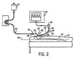
図2を参照すると、本願発明の第2の実施例を示す。ここで同様の参照番号は同様の要素に用いる。図2に示す実施例では、特殊化した補給管60を用いる。特に、補給管60は、双管腔補給管である。これは、第1の管腔62と第2の管腔64を含む。図示の通り、第1の管腔62は、雌の接続器66を含む。雌の接続器66は結合する雄の接続器68を受ける。雄の接続器68は供給導管26のものである。第1の管腔62は、患者の胃18の中まで延長し、補給溶液を患者12に供給する。 Referring to FIG. 2, a second embodiment of the present invention is shown. Here, like reference numerals are used for like elements. In the embodiment shown in FIG. 2, a
双管腔補給管60の第2の管腔64は、第1の端と、第2の端67とを含む。第1の端は、患者の胃18の中まで延長する。第2の端67は、患者の体の外に延長し、検出導管38を受ける。本発明の好適な実施例においては、第2の管腔64は、患者の胃と流体連結する。また、検出導管38は、検出導管38の第2の端44の接続器46に圧力変換器50が接続すると、空気で満たされる。第2の管腔64の第1の端は、患者の胃18の中まで延長しているので、第2の管腔64の第1の端は、患者の腋窩中央線58の高さにある。 The
圧力変換器50が第2の管腔64に接続すると、少量の流体が第2の管腔64を満たす。すると、検出導管38の内部に含まれる空気の体積を圧縮する。検出導管38の内部の圧力を、圧力変換器50が検出する。圧力変換器50は信号を患者観察器56に渡し、表示させる。 When the
図2から解る通り、双管腔補給管60により、患者12の腹圧を直接観察できる。これは第2の管腔64を活用することによる。第2の管腔64は、第1の管腔62から分かれる。第1の管腔62は、補給溶液を患者12に供給するために用いられる。このシステムは、患者12の腹圧を測定するのに大変よく機能する。しかし、このシステムは、特殊化した補給管60を必要とする。これは、ほとんどの救命救急診療環境では、まだ利用可能でないかもしれない。 As can be seen from FIG. 2, the abdominal pressure of the patient 12 can be directly observed by the dual
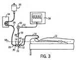
図3を参照すると、本願発明のまた別の実施例を示す。図3の実施例においては、補給管14の雌の接続器32は、圧力適合器70を受ける。圧力適合器70は、本体72を含む。本体72は、雄の接続器を有する。この雄の接続器は、雌の接続器32で受ける。本体72は、雌の接続器74を有する。雌の接続器74は、雄の接続器30を受ける。雄の接続器30は、供給導管26の部分として形成される。従って、供給容器20からの補給溶液の供給は、補給ポンプ34によって、圧力適合器70の本体72を通って、補給管14の中に、押し込まれる。 Referring to FIG. 3, another embodiment of the present invention is shown. In the embodiment of FIG. 3, the
図3に示す通り、検出導管38の第1の端42は、圧力適合器70の本体72に入る。圧力適合器70の本体72は、雌の結合器74と雄の結合器との間にある。好適には、検出導管38は、圧力適合器70と一体に形成される。これにより、圧力適合器70と検出導管38の組み合わせの全体を、単一の使い捨て部として供給できる。 As shown in FIG. 3, the
図1に示した第1の実施例において述べた通り、患者12の体内の圧力により、補給溶液のある体積が、検出導管の中に入ることになる。これにより、検出導管38の内部の空気の体積が圧縮される。圧力の測定値を得るために、補給溶液と空気の体積の分岐点47を、患者の腋窩中央線58の高さに位置させる。補給ポンプ34の動作を中断した後は、圧力変換器50からの圧力信号は、患者12の体内の圧力に直接関連する。従ってこの信号を患者観察器56に記録することができる。好適には、検出導管38は空気濾過器59を含む。これにより、患者に供給している補給溶液の汚染を防ぐ。 As described in the first embodiment shown in FIG. 1, due to pressure within the
図3に示す実施例を、標準的な補給管14と標準的な供給導管26で活用できる。これは単に、圧力適合器70を、補給管14と供給導管26の間の通常の接続点に、挿入すればよい。前述の通り、検出導管38は好適には、圧力適合器の本体72及び空気濾過器59と一体に形成される。これにより、この全体を単一の部として適用できる。すると、この単一の部に圧力変換器50を接続できる。 The embodiment shown in FIG. 3 can be utilized with a
図4を参照すると、本願発明の更にまた別の実施例を示す。図4の実施例においては、補給ポンプ34は内部の圧力変換器76を含む。内部の圧力変換器76は、図1〜図3に示した圧力変換器50と同様に動作する。図4の実施例においては、検出導管38は、供給導管26と流体連結する。検出導管38は、空気濾過器59を含む。検出導管38は、接続器を含む。接続器は、補給ポンプ34に備わる対となる接続器と接続する。前述の実施例と同様に、検出導管38の中の空気と流体の分岐点は、患者12の腋窩中央線58の高さに位置する。これにより、圧力変換器76は、患者12の腹圧を測定できる。図4に示す実施例では、補給ポンプ34は、表示器78を含む。表示器78は、患者から検出した腹圧を表示するように動作できる。 Referring to FIG. 4, yet another embodiment of the present invention is shown. In the embodiment of FIG. 4, the
図4に示す実施例では、補給ポンプ34は、既定の時間間隔で動作を中断するようにプログラムされている。これにより、患者の胃又は空腸の本当の圧力を測定する。ポンプが停止している間に、圧力信号を電子的に処理して、いかなる望まれない信号をも濾過し、所望の信号を取り出す。所望の信号とは、例えば、1呼吸周期における最低圧力水準、及び、心臓のポンプ活動に関連する圧力の変動である。補給ポンプ34の表示器78は、前述の派生した計測値も表示できる。 In the embodiment shown in FIG. 4, the
補給ポンプ34が動作を再開すると、補給ポンプ34の中の処理装置は、圧力を計算できる。この圧力は、この段階では、補給溶液の流れから生ずる圧力に、流れ抵抗を乗算したものを含む。この流れ抵抗は、T字型の接続器80と補給管14の端との間のものである。補給ポンプ34は、供給導管26又は補給管14のいかなる大きな閉塞又は小さな閉塞も、継続的に監視できる。補給ポンプ34は、閉塞を発見したら、栄養補給器具一式又は補給管を交換するようにとの警告を生成してもよい。 When the
前述の記載から解る通り、本願発明の方法及び装置は、栄養補給器具一式又は補給管の圧力を、患者12の腹圧の表示として利用する。圧力変換器は、検出導管の内部の空気の圧力を検出する。この圧力は、患者12の腹圧と直接関係する。圧力変換器は、圧力信号を患者観察器56又は表示器78に提供する。患者観察器56又は表示器78は、その患者の腹圧を連続的又は間欠的に表示できる。 As will be appreciated from the foregoing description, the method and apparatus of the present invention utilizes the complete feeding device or supply tube pressure as an indication of the abdominal pressure of the
図5〜図7は、本発明の追加の実施例を示す。ここで、同様の参照番号を用いて、図1〜図4に示す実施例の、類似の要素を参照する。同様の参照番号を用いて理解を促進する。 5-7 illustrate additional embodiments of the present invention. Here, like reference numerals are used to refer to similar elements of the embodiment shown in FIGS. Similar reference numbers are used to facilitate understanding.
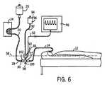
図5に示す実施例では、腹圧測定システム及び装置82は、補給ポンプ34を含む。補給ポンプ34は、供給容器20からの補給溶液の供給を、患者の胃18に押し込む。特に、補給溶液の供給は、供給導管26を通って流れ、鼻―腸補給管14に入る。このときに雄の接続器30と雌の接続器32を通る。腹圧測定装置82は検出導管84を含む。検出導管84は、接続点40で供給導管26に接続する。特に、中空で管状の検出導管84の第1の端86は、供給導管26と接続し流体連結する。この接続は、補給ポンプ34と、供給導管26の第2の端28との間の点で行われる。本発明の図示の実施例では、供給導管26は、T字型の接続器を含む。この接続器は供給導管26の途中に位置する。この接続器は、検出導管84の第1の端86と接続する枝を含む。 In the embodiment shown in FIG. 5, the abdominal pressure measurement system and
検出導管84の第2の端88は、圧力変換器90を受ける。圧力変換器90は、従来からある部品である。圧力変換器90は、以前の実施例で述べた圧力変換器50に似ている。圧力変換器90は、出力線52に信号を生成する。この信号は圧力変換器90が検出した圧力に関連する。出力線52を、患者観察器56の入力54で受ける。これにより、患者観察器56は、圧力変換器90からの圧力の測定値を表示できる。 The
図5に示す通り、圧力変換器90は、流体導管92を受ける。流体導管92は供給容器94から延長する。供給容器94は検出流体96を含む。流体導管92は、圧力変換器90の上部で、検出導管84の延長の役割を果たす。好適な実施例では、検出流体96は殺菌済み生理的食塩水である。勿論他の流体も考えられる。図5に示す通り、供給容器94は、患者の腋窩中央線58より上に上げられている。これにより、検出流体96に圧力をかける。代わりに、供給容器94に、圧迫帯で圧力をかけてもよい。これは血圧を測る際の通常のやり方である。また別の可能性は、圧力変換器90を供給容器94無しに用いることである。この場合、ある量の殺菌済み生理的食塩水を、圧力変換器90に、3方向接続器で随時注入する。これにより導管と鼻―腸補給管14を洗滌する。 As shown in FIG. 5, the
栄養補給溶液が患者に供給容器20から供給される場合、栄養補給溶液は、患者に供給導管26を通ってプログラム可能な流率で向けられる。補給溶液が供給導管26にポンプで押し込まれるにつれ、ある体積の検出流体96は圧力変換器90を通って流れ、供給導管26に流入する。この際に、検出流体96は、検出導管84を通る。これにより、検出流体の連続的な流れができる。例えば、検出流体96の流れは、典型的には3 ml/時程度である。これにより、圧力変換器90を継続的に洗滌する流れを作る。検出流体96は好適には殺菌済み生理的食塩水である。従って、検出流体96が患者の体内に低い流率で入っても、患者の健康には何の影響もない。 When the nutritional solution is supplied to the patient from the
図5に示す通り、圧力変換器90が、患者の腋窩中央線58の高さに並んで位置すれば、検出導管84の内部の検出流体の圧力は、患者の腹圧に直接関連する。圧力変換器90が測定する検出流体の圧力を、すると、患者観察器56の表示画面57に表示できる。 As shown in FIG. 5, if the
圧力変換器90を、患者の腋窩中央線58と同じ高さに置いたなら、検出導管84中に検出される合計圧力Ptは、患者の腹圧に圧力差分dP = F x Rを加えたものと等しい。ここでFは補給溶液の流率であり、Rは流れの抵抗である。圧力変換器90は、検出導管84の内部の検出流体の圧力を検出する。圧力変換器は、検出したその圧力に基づいて信号を生成する。流率が低い場合、消化管中の圧力に比べてdPも低くなり、従って圧力の測定値は腹圧を近似することになる。流率が高い場合、又は供給導管26若しくは補給管14が詰まっている場合は、dPは高くなる可能性があり、腹圧を実質的に過大評価することにつながりうる。この理由により、補給ポンプ34の動作を時々止めるのが望ましい。これにより、正しい腹圧の値を測定し、供給導管26又は補給管14のいかなる詰まりも検出する。 If the
図5aに追加の実施例を示す。ここでは、図5の鼻―腸補給管14を、特殊な補給管60で置き換える。この特殊な補給管60は、図2に示す特殊な補給管60と似ている。前述の通り、補給管60は、双管腔補給管である。これは、第1の管腔62と第2の管腔64を含む。第1の管腔62は、雌の接続器66を含む。雌の接続器66は、結合する雄の接続器68を受ける。雄の接続器68は、供給導管26のものである。第1の管腔62は、患者の胃又は小腸の中まで延長し、補給溶液を患者12に供給する。 An additional embodiment is shown in FIG. Here, the nasal-
第2の管腔64は、第1の端と、第2の端とを含む。第1の端は、患者の胃又は小腸の中まで延長する。第2の端は、患者の体の外に延長し、検出導管84を受ける。図5に示す実施例と同様に、検出導管84の第2の端88は、圧力変換器90を受ける。圧力変換器90は、流体導管92を受ける。流体導管92は供給容器94から延長する。供給容器94は検出流体96を含む。 The
栄養補給溶液が、患者に、供給容器20から、供給される場合、ある体積の検出流体96が、圧力変換器90を通って流れ、鼻―腸補給管60に流入する。この際に、検出流体96は、第2の管腔64を通る。しかし、図5aに示す実施例では、補給ポンプ34を、取り除ける又は外せる。検出流体96は第2の管腔64に供給され、第1の管腔62を通る補給溶液の流れを必要としないからである。従って、図5aに示す実施例は、補給ポンプ34が動作していてもしていなくても、患者の腹圧を測定できる。 When a nutritional solution is supplied to the patient from the
患者の腹圧を測定するのに加えて、図5及び図5aに示すシステム及び装置を利用して、圧力変換器90、検出導管84、供給導管26及び鼻―腸補給管14を間欠的に洗滌できる。とりわけ、システムの洗滌が必要な場合、圧力変換器90を洗滌流率状態にする。すると、検出流体96は、圧力変換器90及び検出導管84を、洗滌用の高い流率で通って流れることができる。検出流体(例えば生理的食塩水)の、この比較的高い流率により、システムの構成部品を洗滌する。上述の記載から解る通り、圧力をかけた供給容器94の内部の検出流体96の供給量が十分であれば、検出流体96は、供給導管26及び補給管14の全体を満たすことができる。これにより、検出流体96のみを利用し、補給溶液を用いずに、患者の腹圧を測定できる。 In addition to measuring the patient's abdominal pressure, the system and apparatus shown in FIGS. 5 and 5a are used to intermittently connect the
図6を参照すると、また別な実施例を示す。この実施例は、検出流体96の、高い位置にある供給容器94を利用する。これにより患者12の腹圧を測定する。しかし、図6に示す実施例では、補給管14の雌の接続器32は、圧力適合器98を受ける。圧力適合器98は、本体100を含む。本体100は、雄の接続器を有する。この雄の接続器は、雌の接続器32で受ける。本体100は、雌の接続器102を有する。雌の接続器102は、雄の接続器30を受ける。雄の接続器30は、供給導管26の部分として形成される。従って、供給容器20からの補給溶液の供給は、補給ポンプ34によって、圧力適合器98の本体100を通って、補給管14の中に、押し込まれる。 Referring to FIG. 6, another embodiment is shown. This embodiment utilizes a
図6に示す通り、検出導管84は、圧力適合器98の本体100に入る。好適には、検出導管84は、圧力適合器98と一体に形成される。これにより、圧力適合器98と検出導管84の組み合わせの全体を、単一の使い捨て部として供給できる。 As shown in FIG. 6, the
図5に示した実施例について述べた通り、圧力変換器90は、患者の腋窩中央線58の高さに並んで位置する。これにより、検出導管84の内部で供給容器94から受ける、検出流体の圧力の測定値を得る。 As described with respect to the embodiment shown in FIG. 5, the
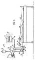
図7を参照すると、本発明のまた別の実施例を示す。図7に示す実施例では、検出導管84は垂直に位置する、透明な圧力計の管104である。この検出導管は、供給導管26と流体連結する。この圧力計の管104は、空気濾過器106を含む。空気濾過器106は、圧力計の管104の第2の端108の近くに取り付けられる。空気濾過器106により、圧力計の管104の内部と大気との平衡が可能となる。他方、空気濾過器106により、圧力計の管104の内部に含まれる流体の汚染を防ぐことができる。 Referring to FIG. 7, yet another embodiment of the present invention is shown. In the embodiment shown in FIG. 7, the
図7に示す通り、検出導管84は供給導管26と接続点40で流体連結する。圧力計の管104は、空気濾過器106を通じて大気と通気しているので、補給溶液は検出導管84に入ることになる。圧力計の管104の中の補給溶液の液柱110の高さは、患者の腹圧を反映する。液柱110の高さを、測定装置112を用いて測定できる。測定装置112の例は定規である。液柱110の高さを測定する際に、定規112の原点を、患者の腋窩中央線58の高さに合わせる。すると、液柱110の高さは、腋窩中央線58より上で測定される。代わりに、目盛りを圧力計の管104に直接印刷してもよい。この場合も、液柱110の高さを測定する前に、圧力計の管104に印刷した目盛りの原点を、患者の腋窩中央線58の高さに合わせる。 As shown in FIG. 7, the
前述の諸実施例と似て、圧力計の管104の液柱110の高さPtは、消化管中の圧力に圧力差分dP = F x Rを加えたものと等しい。ここでFは補給溶液の流率であり、Rは流れの抵抗である。前述の諸実施例の通り、補給ポンプ34を時々止めるのが望ましい。これにより、正しい腹圧の値を測定すると共に、供給導管26又は補給管14のいかなる詰まりも検出する。 Similar to the previous embodiments, the height Pt of the
本願発明について複数の実施例を図面を用いて図示し記述した。しかし、発明者は次のように考えている:患者の腹圧を測定するために、様々な他の方法及び装置を利用することができる。この際に鼻―腸補給管を通って患者に供給される液体の圧力を利用する。 A plurality of embodiments of the present invention have been illustrated and described with reference to the drawings. However, the inventor believes that: Various other methods and devices can be used to measure a patient's abdominal pressure. At this time, the pressure of the liquid supplied to the patient through the nasal-intestinal supply tube is used.
Claims (24)
Translated fromJapanese前記補給管を通って前記患者にポンプで入れられる補給溶液の前記供給と流体連結する検出導管を位置付ける工程;
前記検出導管の中で圧力を計測する工程;及び
前記患者の前記腹圧を、前記検出導管の中で計測した前記圧力に基づいて、測定する工程;
を含む。A method for measuring a patient's abdominal pressure, wherein the patient has a supply tube for supplying a supply solution to the patient, the method comprising:
Positioning a detection conduit in fluid communication with the supply of replenishment solution to be pumped into the patient through the refill tube;
Measuring pressure in the detection conduit; and measuring the abdominal pressure of the patient based on the pressure measured in the detection conduit;
including.
前記圧力計を、前記患者観察器に接続する工程;
を更に含む、請求項2の方法。Positioning a pressure gauge at a second end of the detection conduit; and connecting the pressure gauge to the patient observer;
The method of claim 2 further comprising:
前記検出導管の中の前記空気の前記圧力を計測する前に、前記患者への補給溶液の前記供給を中断する工程;
を更に含む、請求項3の方法。Locating a branch point between the volume of air in the detection conduit and the supply of replenishment solution in the detection conduit at the patient's axillary centerline; and Interrupting the supply of replenishment solution to the patient before measuring the pressure;
The method of claim 3 further comprising:
測定された前記腹圧を前記補給ポンプに表示する工程;
を更に含む、請求項1の方法。Positioning a pressure gauge in a supply pump, wherein the supply pump operates to provide the patient with the supply of supply solution, the pressure gauge measuring the pressure of air in the detection conduit. Displaying the measured abdominal pressure on the supply pump;
The method of claim 1 further comprising:
前記補給管の中で前記補給溶液の圧力を計る工程;及び
計った前記圧力を前記腹圧として患者観察器に表示する工程;
を更に含む、請求項1の方法。Pumping the replenishment solution into the patient through the refill tube;
Measuring the pressure of the replenishing solution in the replenishing tube; and displaying the measured pressure on the patient observer as the abdominal pressure;
The method of claim 1 further comprising:
前記患者に前記補給溶液をポンプで入れる前記工程を中断する工程;及び
前記検出導管の中の前記空気の圧力を検出することによって、前記患者の前記腹圧を測定する工程;
を更に含む、請求項10の方法。Positioning the bifurcation point between the volume of air in the detection conduit and the supply of replenishment solution at the patient's axillary midline;
Interrupting the step of pumping the replenishment solution into the patient; and measuring the abdominal pressure of the patient by detecting the pressure of the air in the detection conduit;
The method of claim 10, further comprising:
前記鼻―腸補給管と流体連結する検出導管を位置付ける工程;
検出流体の供給を前記検出導管を通して前記鼻―腸補給管に流す工程;
前記検出導管の中で前記検出流体の圧力を計測する工程;及び
前記患者の前記腹圧を、計測した前記検出流体の前記圧力に基づいて、測定する工程;
を含む。A method for measuring abdominal pressure in a patient, wherein the patient has a nasal-intestinal supply tube, the method comprising:
Positioning a detection conduit in fluid communication with the nasal-intestinal supply tube;
Flowing a supply of detection fluid through the detection conduit to the nasal-intestinal supply tube;
Measuring the pressure of the detection fluid in the detection conduit; and measuring the abdominal pressure of the patient based on the measured pressure of the detection fluid;
including.
前記圧力計を前記患者の腋窩中央線に合わせる工程;
を含む、請求項12の方法。Positioning a pressure gauge to measure the pressure of the detection fluid in the detection conduit; and aligning the pressure gauge to a central line of the patient's axilla;
The method of claim 12 comprising:
前記補給管と流体連結する第1の端を有する検出導管;及び
前記検出導管の第2の端に接続する圧力変換器、ここで前記圧力変換器は、前記検出導管の中で圧力を検出する;
を含む。A system for measuring a patient's abdominal pressure, wherein the patient has a supply tube for supplying a supply solution to the patient, the system comprising:
A sensing conduit having a first end in fluid communication with the make-up tube; and a pressure transducer connected to the second end of the sensing conduit, wherein the pressure transducer senses pressure in the sensing conduit ;
including.
Applications Claiming Priority (5)
| Application Number | Priority Date | Filing Date | Title |
|---|---|---|---|
| US11/445,715US20070282219A1 (en) | 2006-06-02 | 2006-06-02 | Method and system for measuring the intra-abdominal pressure of a patient |
| US11/445,715 | 2006-06-02 | ||
| US11/683,693 | 2007-03-08 | ||
| US11/683,693US7572235B2 (en) | 2006-06-02 | 2007-03-08 | Method and system of measuring IAP using a naso-enteric tube |
| PCT/IB2007/002308WO2007141658A2 (en) | 2006-06-02 | 2007-05-31 | Method and system of measuring the intra-abdominal pressure of a patient |
Publications (2)
| Publication Number | Publication Date |
|---|---|
| JP2010505452Atrue JP2010505452A (en) | 2010-02-25 |
| JP5036812B2 JP5036812B2 (en) | 2012-09-26 |
Family
ID=38740540
Family Applications (1)
| Application Number | Title | Priority Date | Filing Date |
|---|---|---|---|
| JP2009512705AExpired - Fee RelatedJP5036812B2 (en) | 2006-06-02 | 2007-05-31 | System for measuring patient abdominal pressure |
Country Status (6)
| Country | Link |
|---|---|
| US (1) | US7572235B2 (en) |
| EP (1) | EP2032026A2 (en) |
| JP (1) | JP5036812B2 (en) |
| AU (1) | AU2007257595B2 (en) |
| CA (1) | CA2660462C (en) |
| WO (1) | WO2007141658A2 (en) |
Families Citing this family (9)
| Publication number | Priority date | Publication date | Assignee | Title |
|---|---|---|---|---|
| US20080027373A1 (en)* | 2006-07-27 | 2008-01-31 | Bo Holte | Method and apparatus for the measurement of intra-abdominal pressure utilizing a pressure transducer |
| US8193778B2 (en) | 2007-07-13 | 2012-06-05 | Sanyo Electric Co., Ltd. | Method of charging a battery array |
| WO2009012441A2 (en)* | 2007-07-19 | 2009-01-22 | C. R. Bard, Inc. | Ng tube with gastric volume detection |
| RU2358330C1 (en)* | 2008-01-28 | 2009-06-10 | Государственное образовательное учреждение высшего профессионального образования "БАШКИРСКИЙ ГОСУДАРСТВЕННЫЙ МЕДИЦИНСКИЙ УНИВЕРСИТЕТ Федерального Агентства по здравоохранению и социальному развитию" (ГОУ ВПО БГМУ РОСЗДРАВА) | Method of defining intraperitoneal pressure in experiment with small laboratory animals |
| US8529471B2 (en)* | 2008-12-03 | 2013-09-10 | Holtech Medical | Method and system for the determination of residual volume in patients having an enteral feeding tube |
| DE102009017034B3 (en)* | 2009-04-09 | 2010-06-17 | Pulsion Medical Systems Ag | Device for measuring the bubble pressure |
| CA2788082C (en)* | 2010-01-28 | 2018-02-20 | Art Healthcare Ltd. | Method and device of detecting and/or blocking reflux |
| US9820915B2 (en) | 2010-03-22 | 2017-11-21 | Art Healthcare Ltd. | Naso/orogastric tube having one or more backflow blocking elements, backflow blocking elements, and a method of using backflow blocking elements |
| CN102631191B (en)* | 2012-03-27 | 2014-04-23 | 苏州达维生物医药有限公司 | System and method for monitoring bladder pressure and abdominal pressure |
Citations (4)
| Publication number | Priority date | Publication date | Assignee | Title |
|---|---|---|---|---|
| US3860000A (en)* | 1973-07-12 | 1975-01-14 | Lear Siegler Inc | Medical apparatus and method for feeding and aspirating |
| US20040054350A1 (en)* | 2002-09-17 | 2004-03-18 | Shaughnessy Michael C. | Enteral feeding unit having a reflux device and reflux method |
| JP2004514525A (en)* | 2000-12-05 | 2004-05-20 | ホルテヒ メディカル | Method and apparatus for measuring intra-abdominal pressure |
| WO2004078235A2 (en)* | 2003-03-04 | 2004-09-16 | Wolfe Tory Medical, Inc. | Apparatus for monitoring intra-abdominal pressure |
Family Cites Families (13)
| Publication number | Priority date | Publication date | Assignee | Title |
|---|---|---|---|---|
| US3980082A (en) | 1975-03-14 | 1976-09-14 | William Miller | Venous pressure indicator |
| US4184484A (en) | 1977-10-11 | 1980-01-22 | Ballard D. Wright | Body fluid pressure indicator and regulator and method for continuously regulating and monitoring the pressure of a body fluid |
| US4170224A (en) | 1977-10-25 | 1979-10-09 | Baxter Travenol Laboratories, Inc. | Body fluid measuring device |
| US4217911A (en) | 1978-10-27 | 1980-08-19 | The Kendall Company | Cystometry system |
| SE438962B (en) | 1983-05-18 | 1985-05-28 | Gambro Crafon Ab | BODY RINSE RINSE SYSTEM |
| US4711248A (en) | 1983-12-01 | 1987-12-08 | Biokinetics, Inc. | Physiological pressure monitor |
| DE3563814D1 (en) | 1984-02-23 | 1988-08-25 | Unitika Ltd | Bladder assist device |
| US4727887A (en) | 1985-07-08 | 1988-03-01 | Habley Medical Technology Corporation | Hypodermic manometer |
| US4841984A (en) | 1985-09-16 | 1989-06-27 | Armoor Ophthalmics, Inc. | Fluid-carrying components of apparatus for automatic control of intraocular pressure |
| GB8623020D0 (en) | 1986-09-24 | 1986-10-29 | Young D E | Incontinence diagnostic & treatment device |
| US5211642A (en) | 1991-10-28 | 1993-05-18 | Clendenning Beverly F | Chambers drainage system |
| US5433216A (en)* | 1993-06-14 | 1995-07-18 | Mountpelier Investments, S.A. | Intra-abdominal pressure measurement apparatus and method |
| AU2003901057A0 (en)* | 2003-03-10 | 2003-03-20 | Zsolt Balosh | Intra-abdominal urinary catheter pressure monitor |
- 2007
- 2007-03-08USUS11/683,693patent/US7572235B2/ennot_activeExpired - Fee Related
- 2007-05-31CACA2660462Apatent/CA2660462C/ennot_activeExpired - Fee Related
- 2007-05-31JPJP2009512705Apatent/JP5036812B2/ennot_activeExpired - Fee Related
- 2007-05-31EPEP07789622Apatent/EP2032026A2/ennot_activeWithdrawn
- 2007-05-31WOPCT/IB2007/002308patent/WO2007141658A2/enactiveApplication Filing
- 2007-05-31AUAU2007257595Apatent/AU2007257595B2/ennot_activeCeased
Patent Citations (5)
| Publication number | Priority date | Publication date | Assignee | Title |
|---|---|---|---|---|
| US3860000A (en)* | 1973-07-12 | 1975-01-14 | Lear Siegler Inc | Medical apparatus and method for feeding and aspirating |
| JP2004514525A (en)* | 2000-12-05 | 2004-05-20 | ホルテヒ メディカル | Method and apparatus for measuring intra-abdominal pressure |
| US20040054350A1 (en)* | 2002-09-17 | 2004-03-18 | Shaughnessy Michael C. | Enteral feeding unit having a reflux device and reflux method |
| WO2004078235A2 (en)* | 2003-03-04 | 2004-09-16 | Wolfe Tory Medical, Inc. | Apparatus for monitoring intra-abdominal pressure |
| JP2007524434A (en)* | 2003-03-04 | 2007-08-30 | ウォルフ トーリー メディカル インコーポレーティッド | Device for monitoring abdominal pressure |
Also Published As
| Publication number | Publication date |
|---|---|
| WO2007141658A3 (en) | 2008-02-21 |
| JP5036812B2 (en) | 2012-09-26 |
| AU2007257595A1 (en) | 2007-12-13 |
| EP2032026A2 (en) | 2009-03-11 |
| US20070282307A1 (en) | 2007-12-06 |
| US7572235B2 (en) | 2009-08-11 |
| AU2007257595B2 (en) | 2013-03-14 |
| AU2007257595A2 (en) | 2009-02-19 |
| WO2007141658A2 (en) | 2007-12-13 |
| CA2660462C (en) | 2012-12-04 |
| CA2660462A1 (en) | 2007-12-13 |
Similar Documents
| Publication | Publication Date | Title |
|---|---|---|
| JP5036812B2 (en) | System for measuring patient abdominal pressure | |
| US11553865B2 (en) | Bladder health monitoring systems and related methods and devices | |
| JP7661280B2 (en) | CATHETER ASSEMBLY INCLUDING MONITORING CAPABILITIES - Patent application | |
| US20070282219A1 (en) | Method and system for measuring the intra-abdominal pressure of a patient | |
| CN102596023B (en) | Systems, methods and devices for facilitating access to an anatomical site or environment | |
| AU2005310110A1 (en) | Continuous intra-abdominal pressure monitoring urinary catheter with optional core temperature sensor | |
| JP7682899B2 (en) | Diagnostic system including a temperature-sensitive vascular device | |
| JP2614888B2 (en) | Multi-lumen catheter for thermodilution measurement | |
| US7883472B2 (en) | Method and system of measuring IAP using a naso-enteric tube | |
| AU2015223182B2 (en) | Patient monitoring system with gatekeeper signal | |
| JP7232198B2 (en) | System for monitoring physiological parameters in cardiopulmonary bypass | |
| BR112019017398B1 (en) | SYSTEM FOR MONITORING PHYSIOLOGICAL PARAMETERS IN EXTRACORPOREAL CIRCULATION |
Legal Events
| Date | Code | Title | Description |
|---|---|---|---|
| A621 | Written request for application examination | Free format text:JAPANESE INTERMEDIATE CODE: A621 Effective date:20100223 | |
| A977 | Report on retrieval | Free format text:JAPANESE INTERMEDIATE CODE: A971007 Effective date:20120202 | |
| A131 | Notification of reasons for refusal | Free format text:JAPANESE INTERMEDIATE CODE: A131 Effective date:20120214 | |
| A521 | Request for written amendment filed | Free format text:JAPANESE INTERMEDIATE CODE: A523 Effective date:20120510 | |
| TRDD | Decision of grant or rejection written | ||
| A01 | Written decision to grant a patent or to grant a registration (utility model) | Free format text:JAPANESE INTERMEDIATE CODE: A01 Effective date:20120605 | |
| A01 | Written decision to grant a patent or to grant a registration (utility model) | Free format text:JAPANESE INTERMEDIATE CODE: A01 | |
| A61 | First payment of annual fees (during grant procedure) | Free format text:JAPANESE INTERMEDIATE CODE: A61 Effective date:20120703 | |
| FPAY | Renewal fee payment (event date is renewal date of database) | Free format text:PAYMENT UNTIL: 20150713 Year of fee payment:3 | |
| R150 | Certificate of patent or registration of utility model | Free format text:JAPANESE INTERMEDIATE CODE: R150 | |
| LAPS | Cancellation because of no payment of annual fees |