JP2010504580A - RFID device expansion function - Google Patents
RFID device expansion functionDownload PDFInfo
- Publication number
- JP2010504580A JP2010504580AJP2009528845AJP2009528845AJP2010504580AJP 2010504580 AJP2010504580 AJP 2010504580AJP 2009528845 AJP2009528845 AJP 2009528845AJP 2009528845 AJP2009528845 AJP 2009528845AJP 2010504580 AJP2010504580 AJP 2010504580A
- Authority
- JP
- Japan
- Prior art keywords
- rfid device
- rfid
- reading
- communication interface
- communication
- Prior art date
- Legal status (The legal status is an assumption and is not a legal conclusion. Google has not performed a legal analysis and makes no representation as to the accuracy of the status listed.)
- Pending
Links
Images


Classifications
- G—PHYSICS
- G06—COMPUTING OR CALCULATING; COUNTING
- G06K—GRAPHICAL DATA READING; PRESENTATION OF DATA; RECORD CARRIERS; HANDLING RECORD CARRIERS
- G06K19/00—Record carriers for use with machines and with at least a part designed to carry digital markings
- G06K19/06—Record carriers for use with machines and with at least a part designed to carry digital markings characterised by the kind of the digital marking, e.g. shape, nature, code
- G06K19/067—Record carriers with conductive marks, printed circuits or semiconductor circuit elements, e.g. credit or identity cards also with resonating or responding marks without active components
- G06K19/07—Record carriers with conductive marks, printed circuits or semiconductor circuit elements, e.g. credit or identity cards also with resonating or responding marks without active components with integrated circuit chips
- G06K19/0723—Record carriers with conductive marks, printed circuits or semiconductor circuit elements, e.g. credit or identity cards also with resonating or responding marks without active components with integrated circuit chips the record carrier comprising an arrangement for non-contact communication, e.g. wireless communication circuits on transponder cards, non-contact smart cards or RFIDs
Landscapes
- Engineering & Computer Science (AREA)
- Computer Networks & Wireless Communication (AREA)
- Computer Hardware Design (AREA)
- Microelectronics & Electronic Packaging (AREA)
- Physics & Mathematics (AREA)
- General Physics & Mathematics (AREA)
- Theoretical Computer Science (AREA)
- Near-Field Transmission Systems (AREA)
- Storage Device Security (AREA)
Abstract
Translated fromJapaneseDescription
Translated fromJapanese本発明は、無線周波数識別(RFID)装置の分野に関する。特に、本発明は、ユーザが持ち運ぶRFIDタグアイテムのプライバシーの保全を可能にするRFID装置に関する。 The present invention relates to the field of radio frequency identification (RFID) devices. In particular, the present invention relates to an RFID device that enables privacy preservation of RFID tag items carried by a user.
更に、本発明は、読出用通信インターフェースを有する読出用RFID装置に関する。 The present invention further relates to a reading RFID device having a reading communication interface.
更に、本発明は、前記RFID装置及び前記読出用RFID装置を有するRFIDシステム並びに前記RFID装置に記憶されている情報を取り出す方法に関する。 Furthermore, the present invention relates to an RFID system having the RFID device and the reading RFID device, and a method for extracting information stored in the RFID device.
無線周波数識別(RFID)は、例えば、スマートラベル又はタグとしての、多数の応用を有する未来技術である。RFID装置及びRFIDタグは、それらの費用及び機能において極めて様々である。ローエンドでは、限られた計算、記憶及び通信能力を有し、読取器から自身の電力を得る受動型の低価格タグが存在する。このようなタグの主な応用には、電気製品コード(EPC)に使用されているバーコードの代替、及び例えば医薬産業で製品偽造を防ぐ追跡ツール(track-and-trace tool)がある。更に、RFIDタグは、生産される各商品の取り扱いを個々に追跡するために生産及び/又は物流で使用される。しかし、RFIDタグは、また、家庭において一意に物品を識別し且つ多数の家庭活動をサポートする可能性を伴って、消費者側での応用も有する。 Radio frequency identification (RFID) is a future technology with numerous applications, for example as a smart label or tag. RFID devices and RFID tags vary greatly in their cost and function. At the low end, there are passive low-cost tags that have limited computational, storage and communication capabilities and get their power from the reader. The main applications of such tags are alternatives to barcodes used in electrical product codes (EPC), and track-and-trace tools that prevent product counterfeiting, for example in the pharmaceutical industry. Furthermore, RFID tags are used in production and / or logistics to individually track the handling of each product produced. However, RFID tags also have consumer applications with the potential to uniquely identify items in the home and support multiple home activities.
しかし、低価格のRFIDタグは、深刻な安全上の問題を提示する。幾つかの場合に、低価格RFID装置は、そのユーザにプライバシー侵害のおそれをもたらしうる。例えば、タグにある情報が、認められていない者に対してその情報を利用可能にすることから保護されていない場合に、このような認められていない者は、人が持ち運んでいるタグ付きアイテムに関する情報を不正に取得することができる。次いで、この情報は、タグ付きのアイテムを持ち運んでいる者を追跡し、その者の好みに関する情報を調査し、個々人の間で起こる取引を推察する等のために使用され得る。RFIDのプライバシーに関する問題の脅威及び利用可能な解決法の詳細な概説については、S.L.Garfinkel、A.Juels、R.Pappu著、「RFID Privacy:An Overview of Problems and Proposed Solutions」、IEEE Security and Privacy、3(3)、34〜43頁、2005年5月/6月(非特許文献1)を参照されたし。 However, low cost RFID tags present a serious safety problem. In some cases, low cost RFID devices can pose a privacy breach to the user. For example, if the information on a tag is not protected from making the information available to unauthorized persons, such unauthorized persons are tagged items carried by the person. It is possible to obtain information regarding This information can then be used to track the person carrying the tagged item, investigate information about their preferences, infer transactions that occur between individuals, and so on. For a detailed review of RFID privacy issues threats and available solutions, see SLGarfinkel, A.Juels, R.Pappu, "RFID Privacy: An Overview of Problems and Proposed Solutions", IEEE Security and Privacy, 3 (3), pages 34 to 43, May / June 2005 (Non-patent Document 1).
現在のシステムにおけるこのような脅威を防ぐための1つの標準化された解決法は、恒久的にタグを無効にする、いわゆる「切断コマンド(kill command)」である。このような解決法は有効ではあるが、例えば売却完了後に、このような切断コマンドを適用する場合はRFIDタグを使用不可能にするという大きな欠点を有する。特に、組み込み型のRFIDタグを有する物は、たとえユーザが望んでも、もはや交信したり、あるいは、情報を適法なユーザへ提供したりすることができない。 One standardized solution to prevent such threats in current systems is the so-called “kill command” that permanently disables the tag. While such a solution is effective, it has the major disadvantage of disabling the RFID tag when applying such a disconnect command, for example after the sale is complete. In particular, objects with embedded RFID tags can no longer communicate or provide information to legitimate users, even if the user desires.
米国特許第6,970,070号明細書(特許文献1)は、RFIDタグに関連してプライバシーを保つ他の解決法を開示する。この解決法は、いわゆる、ブロッカー(blocker)タグの使用を伴う。このタグは、個々の、場合によっては認められていないRFID読取器によって持ち運ばれるRFIDタグの間の壁として有効に働く。ブロッカータグは、その範囲下でタグをシミュレーションし、タグを識別するために読取器によって実行されるシンギュレーション(singulation)プロトコルを妨げる。読取器はタグを識別することができないので、ユーザのプライバシーは守られる。 US Pat. No. 6,970,070 discloses another solution for maintaining privacy in connection with RFID tags. This solution involves the use of so-called blocker tags. This tag effectively serves as a wall between RFID tags carried by individual, possibly unauthorized RFID readers. The blocker tag simulates the tag under that range and interferes with the singulation protocol performed by the reader to identify the tag. Since the reader cannot identify the tag, the user's privacy is preserved.
米国特許出願公開第2004/0222878(A1)号明細書(特許文献2)は、RFID装置の利用に関連してプライバシーを保護することに関する他のアプローチを開示する。このアプローチは、周期的に読取器によって更新されて、ワンタイムパッド(one-time pad)で暗号化されるタグへ送信される偽名(pseudonyms)の使用に基づく。 U.S. Patent Application Publication No. 2004/0222878 (A1) discloses another approach for protecting privacy in connection with the use of RFID devices. This approach is based on the use of pseudonyms that are periodically updated by the reader and sent to tags that are encrypted with a one-time pad.
S.A.Weis、S.E.Sarma、R.L.Rivest、D.W.Engels著、「Security and Privacy Aspects of Low-Cost Radio Frequency Identification Systems」、International Conference on Security in Pervasive Computing、2003年3月(非特許文献2)は、RFID装置に関連してプライバシーを保護する更なる他の解決法を開示する。かかる解決法は、例えばハッシュ関数のような暗号基関数の使用を伴う。しかし、このような解決法は、安価なRFIDタグが有するとは期待されない付加的なリソースを必要とする。 SAWeis, SESarma, RLRivest, DWEngels, "Security and Privacy Aspects of Low-Cost Radio Frequency Identification Systems", International Conference on Security in Pervasive Computing, March 2003 (Non-Patent Document 2) Discloses yet another solution for protecting privacy in connection with. Such a solution involves the use of cryptographic primitives such as hash functions. However, such a solution requires additional resources that are not expected to be possessed by cheap RFID tags.
Bolotnyy,L.及びRobins,G.著、「Multi-Tag Radio Frequency Identification Systems」、Proc.IEEE Workshop on Automated Identification Advanced Technologies、2005年10月、83〜88頁(非特許文献3)は、RFID読取器によって多重RFIDタグシステムで引き起こされる全体的な電圧を増大させることによって多重RFIDタグシステムの感度を高めるための複数のRFIDタグの使用を開示する。特に、異なるRFIDタグが入射角に対して異なる方向に位置付けられている場合に、最も良い指向性のRFIDタグで期待される電圧は有意に増大する。 Bolotnyy, L. and Robins, G., “Multi-Tag Radio Frequency Identification Systems”, Proc. IEEE Workshop on Automated Identification Advanced Technologies, October 2005, pages 83-88 (non-patent document 3) Disclosed is the use of multiple RFID tags to increase the sensitivity of a multiple RFID tag system by increasing the overall voltage caused by the device in the multiple RFID tag system. In particular, when different RFID tags are positioned in different directions with respect to the incident angle, the voltage expected with the best directional RFID tag is significantly increased.
A.Juels著、「RFID Security and Privacy」、A Research Survey、IEEE Journal on Selected Areas in Communications、24(2)、381〜394頁、2006年2月(非特許文献4)は、追跡の問題に対処するために販売時点でタグの一意の識別子を消すが、後の使用のために、例えば、典型的なバーコードデータのような、製品タイプ識別子を残す提案を開示する。消費者製品は新しい識別子を有する新しいタグを備えられるが、古いタグ識別子はリサイクル等の後の公共使用のための再有効化を前提として残ることが示唆されている。この考えを実現するための物理的メカニズムとして、更に、2つのRFIDタグの間で製品タイプの識別子及び一意の識別子を分ける考えを検討することが提案されている。この考えは、ユーザが、自身のデータ放出を制限するようタグを物理的に変更し且つそれらの変更された状態の物理的確認を得ることができる点で拡張され得る。 "RFID Security and Privacy" by A.Juels, A Research Survey, IEEE Journal on Selected Areas in Communications, 24 (2), pages 381-394, February 2006 (Non-Patent Document 4) Disclose the proposal to erase the tag's unique identifier at the point of sale to deal with, but leave the product type identifier, for example, typical barcode data, for later use. It has been suggested that while consumer products are equipped with new tags with new identifiers, old tag identifiers remain subject to revalidation for later public use such as recycling. As a physical mechanism for realizing this idea, it has been proposed to further consider the idea of dividing a product type identifier and a unique identifier between two RFID tags. This idea can be extended in that the user can physically change the tags to limit their data emission and obtain a physical confirmation of their changed state.
米国特許出願公開第2005/0205678(A1)号明細書(特許文献3)は、アンテナと共に第2インターフェースとしての接触インターフェースを有するデュアルインターフェースユニットを有するデータ担体を開示する。開示されるデータ担体内のRFIDユニットは、例えばUSBプラグのような標準インターフェースを介して、インターネット接続可能なパーソナルコンピュータへ接続可能である。 US 2005/0205678 (A1) discloses a data carrier having a dual interface unit with a contact interface as a second interface with an antenna. The RFID unit in the disclosed data carrier can be connected to a personal computer capable of connecting to the Internet via a standard interface such as a USB plug.
一方ではユーザのプライバーを高めることを可能にし、他方ではRFID装置の複雑性及び費用に関して過剰な増大を引き起こさない拡張された機能、すなわち、保護されていないRFID装置と比較してこのような拡張された機能、をRFID装置に提供する必要性がある。 On the one hand, it is possible to increase the user's privacy, and on the other hand, an extended function that does not cause an excessive increase in the complexity and cost of the RFID device, i.e. such an extension compared to an unprotected RFID device. There is a need to provide such functions to RFID devices.
上記の必要性は、独立請求項に係る対象によって満足され得る。本発明の有利な実施形態は、従属請求項によって記載される。 The above need may be met by the subject matter according to the independent claims. Advantageous embodiments of the invention are described by the dependent claims.
本発明の第1の様相に従って、RFID装置が提供される。当該RFID装置は、(a)データメモリ及び(b)このデータメモリへ結合される電子回路配置を有する。該電子回路配置は、第1の動作構造及び第2の動作構造を有する。制御コマンドを受け取ることによって、該電子回路配置は、前記第1の動作構造から前記第2の動作構造へと不可逆に切り換えられ得る。当該RFID装置は、(c)前記電子回路配置へ結合される通信インターフェースを更に有する。前記第1の動作構造で、当該RFID装置は、前記通信インターフェースを介して標準RFID読取器と通信するよう構成され、前記第2の動作構造で、前記標準RFID読取器との通信は無効にされ、当該RFID装置は、読出用RFID装置と通信するよう構成される。 In accordance with a first aspect of the present invention, an RFID device is provided. The RFID device has (a) a data memory and (b) an electronic circuit arrangement coupled to the data memory. The electronic circuit arrangement has a first operating structure and a second operating structure. By receiving a control command, the electronic circuit arrangement can be irreversibly switched from the first operating structure to the second operating structure. The RFID device further comprises (c) a communication interface coupled to the electronic circuit arrangement. In the first operational structure, the RFID device is configured to communicate with a standard RFID reader via the communication interface, and in the second operational structure, communication with the standard RFID reader is disabled. The RFID device is configured to communicate with the reading RFID device.
本発明のこの様相は、前記制御コマンドにより当該RFID装置の前記通信インターフェースを変更することによって、前記標準RFID読取器がもはや前記データメモリに記憶されるデータを取り出すことができないという考えに基づく。しかし、このようなコマンドによって無効化される既知のRFIDタグとは対照的に、当該RFID装置は、依然として、標準RFID読取器ではなく、少なくとも、特別に設計された読出用RFID装置と通信することができる。 This aspect of the invention is based on the idea that the standard RFID reader can no longer retrieve the data stored in the data memory by changing the communication interface of the RFID device with the control command. However, in contrast to known RFID tags that are invalidated by such commands, the RFID device still communicates with at least a specially designed readout RFID device, not a standard RFID reader. Can do.
前記読出用RFID装置は、当該RFID装置とほとんど同じように使用され得るRFIDタグでありうる。これは、前記読出用RFID装置が、認定ユーザに製品に関する情報を提供するために消費者製品又は他のアイテムへ取り付けられ得る自立型電子装置であることを意味する。 The reading RFID device can be an RFID tag that can be used in much the same way as the RFID device. This means that the readout RFID device is a free-standing electronic device that can be attached to a consumer product or other item to provide authorized users with information about the product.
前記電子回路配置は、前記第1の動作構造から前記第2の動作構造へと当該回路配置を移すよう構成される様々な電子部品、回路経路及び少なくとも1つのスイッチング素子を有するどんなタイプの回路であっても良い。スイッチング素子は、第1接触から第2接触へと回路経路を替える素子でありうる。スイッチング素子は、また、対応する回路経路の途絶が発生するように回路経路を不可逆に開放する素子であっても良い。 The electronic circuit arrangement is any type of circuit having various electronic components, circuit paths and at least one switching element configured to transfer the circuit arrangement from the first operating structure to the second operating structure. There may be. The switching element may be an element that changes a circuit path from the first contact to the second contact. The switching element may also be an element that irreversibly opens a circuit path so that a corresponding circuit path is interrupted.
通常、前記通信インターフェースはアンテナ素子である。このアンテナ素子は、RFIDチップの内部筐体の外に形成されるオフチップのアンテナでありうる。前記筐体は、前記データメモリ、及び/又は前記電子回路配置の少なくとも一部を含む。 Usually, the communication interface is an antenna element. This antenna element can be an off-chip antenna formed outside the internal housing of the RFID chip. The housing includes at least part of the data memory and / or the electronic circuit arrangement.
所定の制御コマンド又は制御信号が外部装置から当該RFID装置へ適用され得る。このコマンドは前記電子回路の配置を不可逆に変更するので、このようなコマンドは、また、変形切断コマンドとも呼ばれることがある。当然、前記制御コマンドは、適切な遠隔制御装置によって生成及び送信される適切な無線周波数信号又はその他無線信号によってトリガ及び/又は誘発され得る。遠隔制御装置は、また、記載されるような機能を有するRFID読取器であっても良い。 A predetermined control command or control signal can be applied from an external device to the RFID device. Since this command irreversibly changes the arrangement of the electronic circuit, such a command may also be called a modified cutting command. Of course, the control command may be triggered and / or triggered by a suitable radio frequency signal or other radio signal generated and transmitted by a suitable remote control device. The remote control device may also be an RFID reader having the functions as described.
語「通信」は、幅広く理解されるべきである。これに関連して、語「通信」は、2つの機関(parties)の間でのどんなタイプのデータ伝送も意味し、これによって、対応する情報は、2方向で、又は1方向でのみ送信される。ここで、第1の通信機関はRFID装置であり、第2の通信機関は読出用RFID装置である。 The term “communication” should be understood broadly. In this context, the word “communication” means any type of data transmission between two organizations, whereby the corresponding information is transmitted in two directions or only in one direction. The Here, the first communication institution is an RFID device, and the second communication institution is a reading RFID device.
本発明の実施形態に従って、当該RFID装置は受動的なRFID装置である。このことは、当該RFID装置が、例えば、価格情報又は契約満期日若しくは個々の電子製品コード(EPC)等のその他の情報を消費者製品に付すために使用され得る安価な電子装置によって実現され得るという利点を提供することができる。それによって、受動的なRFIDは、消費者製品に又は消費者製品のパッケージに組み込まれ得る。受動的なRFID装置の低い製造費用のために、それは、使用後に処分され得る使い捨て商品であっても良い。 According to an embodiment of the present invention, the RFID device is a passive RFID device. This can be achieved by an inexpensive electronic device that can be used to attach the consumer device with other information such as price information or contract expiration date or individual electronic product code (EPC), for example. Can provide the advantage. Thereby, passive RFID can be incorporated into the consumer product or into the package of the consumer product. Because of the low manufacturing cost of passive RFID devices, it may be a disposable item that can be disposed of after use.
受動的なRFID装置又はタグは内部電源を有さないことによって定義されることが言及される必要がある。入来する無線信号によってアンテナ素子で引き起こされる微少電流は、前記電子回路配置のための過不足のない電力を提供する。望ましくは、前記電子回路配置は、当該RFID装置を起動し且つ応答を送信するためにCMOS集積回路を有する。オンボード電源の欠如は、当該装置が極めて小さく且つ極めて安価であることを意味する。従って、商業上利用可能な製品は、ひそかに組み込まれ得る受動的なRFIDチップを提供及び/又は設置され得る。 It should be mentioned that passive RFID devices or tags are defined by having no internal power supply. The minute current caused by the incoming radio signal at the antenna element provides a sufficient power for the electronic circuit arrangement. Preferably, the electronic circuit arrangement comprises a CMOS integrated circuit for activating the RFID device and transmitting a response. The lack of on-board power means that the device is very small and very inexpensive. Thus, commercially available products can be provided and / or installed with passive RFID chips that can be secretly incorporated.
本発明の更なる実施形態に従って、前記第2の動作構造で、当該RFID装置は、プライバシー保全方式で前記読出用RFID装置と通信することができる。それによって、プライバシー面は、当該RFID装置に組み込まれている前記電子回路配置の物理特性に基づく。例えば、プライバシーは、当該RFID装置と前記読出用RFID装置との間の対応するデータ伝送の空間的な補償範囲を制限することによって保たれ得る。しかし、また、暗号化又は符号化プロシージャが、当該RFID装置と前記読出用RFID装置との間のプライバシー保護通信を保証するために使用されても良い。 According to a further embodiment of the present invention, in the second operating structure, the RFID device can communicate with the reading RFID device in a privacy manner. Thereby, the privacy aspect is based on the physical characteristics of the electronic circuit arrangement incorporated in the RFID device. For example, privacy can be maintained by limiting the spatial coverage of the corresponding data transmission between the RFID device and the reading RFID device. However, an encryption or encoding procedure may also be used to ensure privacy-protected communication between the RFID device and the reading RFID device.
本発明の更なる実施形態に従って、前記第2の動作構造で、当該RFID装置の周囲の空間的な読出範囲は、近距離通信、特に、1センチメートルの距離にわたる、望ましくは1ミリメートルの距離にわたる近距離通信に制限される。これには、前記第2の動作構造にある当該RFID装置からデータを取り出すために、前記読出用RFID装置が当該RFID装置に近接して配置される必要があるという効果がある。これは、例えば、直接に又は間接に当該RFID装置の上に又はその隣に前記読出用RFID装置を取付又は設置することによって、達成され得る。 According to a further embodiment of the invention, in the second operating structure, the spatial readout range around the RFID device spans near field communication, in particular over a distance of 1 centimeter, preferably over a distance of 1 millimeter. Limited to near field communication. This has the effect that the reading RFID device needs to be placed close to the RFID device in order to retrieve data from the RFID device in the second operating structure. This can be accomplished, for example, by attaching or installing the readout RFID device directly or indirectly on or next to the RFID device.
本発明の更なる実施形態に従って、前記電子回路配置は、当該RFID装置が前記制御コマンドを受け取る場合に前記通信インターフェースの少なくとも一部を前記データメモリから切り離すよう構成されるスイッチング素子を有する。 According to a further embodiment of the present invention, the electronic circuit arrangement comprises a switching element configured to disconnect at least part of the communication interface from the data memory when the RFID device receives the control command.
スイッチング素子は、前記制御コマンドを受け取ることによって前記データメモリを前記通信インターフェースと接続する導体経路が中断されるように、前記電子回路において配置され得る。それによって、前記データメモリと前記通信インターフェースとの間の完全な切断が達成され得る。コマンド信号に応答するこのようなスイッチング素子は、RFIDタグの分野で幅広く知られている。従って、それらの機能の物理モードについてはより詳細に説明する必要がない。 A switching element may be arranged in the electronic circuit such that a conductor path connecting the data memory with the communication interface is interrupted by receiving the control command. Thereby, a complete disconnection between the data memory and the communication interface can be achieved. Such switching elements responsive to command signals are widely known in the field of RFID tags. Therefore, it is not necessary to describe the physical modes of those functions in more detail.
本発明の更なる実施形態に従って、当該RFID装置は、当該RFID装置と前記読出用RFID装置との間の通信を排他的に可能にするよう構成される更なる通信インターフェースを更に有する。これは、当該RFID装置が少なくとも2つの通信インターフェースを有することを意味する。コマンド信号又は変形切断コマンドを受け取ることによって、第1の通常アンテナに基づく通信インターフェースは無効にされる。従って、標準的なRFID読取装置との通信はもはや可能でない。第2の又は更なる通信インターフェースは、たとえ当該RFID装置又はその第1の通信インターフェースが切断されていても前記読出用RFID装置が当該RFID装置と通信することができるように、前記データメモリへ接続されている。 According to a further embodiment of the invention, the RFID device further comprises a further communication interface configured to exclusively allow communication between the RFID device and the reading RFID device. This means that the RFID device has at least two communication interfaces. By receiving a command signal or a modified disconnect command, the communication interface based on the first normal antenna is disabled. Communication with standard RFID readers is therefore no longer possible. A second or further communication interface is connected to the data memory so that the reading RFID device can communicate with the RFID device even if the RFID device or the first communication interface is disconnected. Has been.
前記第2の通信インターフェースは、前記通信インターフェースによって当該RFID装置と標準RFID読取器との間の通信に使用される周波数とは異なる周波数を有する電磁放射によって前記読出用RFID装置と通信するよう構成される更なるアンテナ素子でありうる。 The second communication interface is configured to communicate with the readout RFID device by electromagnetic radiation having a frequency that is different from a frequency used by the communication interface for communication between the RFID device and a standard RFID reader. Can be further antenna elements.
本発明の更なる実施形態に従って、前記更なる通信インターフェースは、物理接触インターフェース及び/又はガルバニックインターフェースであり、前記読出用RFID装置の対応する読出インターフェースへ接続されるよう構成される。制御又は切断コマンドが発行され、前記第1の通信インターフェースが使用できなくなった後に、前記更なる通信インターフェースを介してのみ当該RFID装置の前記データメモリの中身へのアクセスを得ることが可能である。 According to a further embodiment of the invention, the further communication interface is a physical contact interface and / or a galvanic interface and is configured to be connected to a corresponding readout interface of the readout RFID device. After a control or disconnect command is issued and the first communication interface becomes unusable, it is possible to gain access to the contents of the data memory of the RFID device only via the further communication interface.
本発明の更なる実施形態に従って、前記電子回路配置は、当該RFID装置が前記制御コマンドを受け取る場合に前記通信インターフェースを変更するよう構成されるスイッチング素子を有する。該スイッチング素子を作動させることによって、他の電子部品が加えられ、又は前記データメモリと前記アンテナ素子との間の結合に相当する回路部分から取り除かれ得る。このような電子部品は、例えば、抵抗、ダイオード、コンデンサ及び/又はインダクタでありうる。 According to a further embodiment of the invention, the electronic circuit arrangement comprises a switching element configured to change the communication interface when the RFID device receives the control command. By actuating the switching element, other electronic components can be added or removed from the circuit portion corresponding to the coupling between the data memory and the antenna element. Such electronic components can be, for example, resistors, diodes, capacitors, and / or inductors.
本発明の更なる実施形態に従って、前記スイッチング素子は、当該RFID装置の動作周波数の周波数帯域を変更するよう構成される。これは、当該RFID装置の共振周波数を変更することによる簡単であるが極めて有効な方法で実現され得る。かかる共振周波数は、主に、前記アンテナ素子及び前記電子回路配置の誘導及び容量リアクタンスによって決定される。共振周波数は、特に、前記アンテナ素子からコンデンサを切り離し又は該アンテナ素子へコンデンサを接続することによる有効な方法で変更され得る。それによって、とりわけ前記アンテナ素子を有する発振回路の共振周波数は変更される。対応するコンデンサは、前記アンテナ素子に並列に接続され得る。 According to a further embodiment of the invention, the switching element is configured to change the frequency band of the operating frequency of the RFID device. This can be achieved in a simple but extremely effective way by changing the resonant frequency of the RFID device. Such a resonance frequency is mainly determined by the induction and capacitive reactance of the antenna element and the electronic circuit arrangement. The resonant frequency can be changed in an effective manner, in particular by disconnecting a capacitor from the antenna element or connecting a capacitor to the antenna element. Thereby, in particular, the resonance frequency of the oscillation circuit having the antenna element is changed. A corresponding capacitor may be connected in parallel with the antenna element.
前記動作周波数は、例えば13.56MHzから3.45GHzへと、あるいはその逆に変更され得る。前記第1の動作構造に割り当てられる第1の動作周波数と、前記第2の動作構造に割り当てられる第2の動作周波数との間のこのような大きな差は、(a)当該RFID装置と標準RFID読取器との間の第1の通信と、(b)当該RFID装置と読出用RFID装置との間の第2の通信との間の確実な分離を提供する。 The operating frequency can be changed, for example, from 13.56 MHz to 3.45 GHz or vice versa. Such a large difference between the first operating frequency assigned to the first operating structure and the second operating frequency assigned to the second operating structure is: (a) the RFID device and the standard RFID Providing a secure separation between the first communication with the reader and (b) the second communication between the RFID device and the reading RFID device.
本発明の更なる実施形態に従って、前記スイッチング素子は、当該RFID装置の結合モードを変化させるよう構成される。特に、前記結合モードは、当該RFID装置と前記標準RFID読取器との間の誘導結合から、当該RFID装置と前記読出用RFID装置との間の容量結合へと変化しうる。これは、通常は空間的な補償範囲が縮小されるという利点を提供することができる。これは、更に、当該RFID装置と前記読出用RFID装置との間の通信が認定されていない第三者によって傍聴され得ないこと提供する。当然、また、反対方向での結合モードの変化も可能である。 According to a further embodiment of the invention, the switching element is configured to change the coupling mode of the RFID device. In particular, the coupling mode may change from inductive coupling between the RFID device and the standard RFID reader to capacitive coupling between the RFID device and the reading RFID device. This can provide the advantage that the spatial compensation range is usually reduced. This further provides that communication between the RFID device and the reading RFID device cannot be heard by an unauthorized third party. Of course, a coupling mode change in the opposite direction is also possible.
前記結合モードは、例えば、誘導から容量へと変形切断コマンドによって変更され得る。それによって、該切断コマンドは、当該RFID装置が標準RFID読取器によってもはや問い合わせをされ得ないように、当該RFID装置を無効にする。しかし、前記データメモリに存在するデータは、依然として、専用の読出用RFID装置を介して読み出され得る。 The coupling mode can be changed, for example, from inductive to capacitive by a deformation disconnect command. The disconnect command thereby disables the RFID device so that the RFID device can no longer be interrogated by a standard RFID reader. However, the data present in the data memory can still be read via a dedicated reading RFID device.
本発明の更なる様相に従って、読出用RFID装置が提供される。当該読出用RFID装置は、前出の実施形態のいずれか1つに従うRFID装置の前記電子回路配置が前記第2の動作構造にある場合に、前記RFID装置と通信するよう構成される読出通信インターフェースを有する。 In accordance with a further aspect of the present invention, a read RFID device is provided. The readout RFID device is configured to communicate with the RFID device when the electronic circuit arrangement of the RFID device according to any one of the preceding embodiments is in the second operational structure. Have
本発明のこの更なる様相は、安価な読出装置が提供されるという考えに基づく。かかる読出装置は、たとえ標準RFID読取器がもはや前記RFID装置と通信することができないように前記RFID装置が変更又は無効にされていても、該RFID装置からのデータ取り出しを可能にする。 This further aspect of the invention is based on the idea that an inexpensive readout device is provided. Such a reader allows data retrieval from the RFID device even if the RFID device has been modified or disabled so that a standard RFID reader can no longer communicate with the RFID device.
本発明の実施形態に従って、当該読出用RFID装置は、受動的な読出用RFID装置である。このことは、当該読出用RFID装置が低価格のRFID装置によって実現され得るという利点を有する。これは、前記RFID装置及び当該読出用RFID装置がいずれも小さく且つ安価な電子装置でありうることを意味する。低い製造費用のために、当該受動的な読出用RFID装置は、使用後に処分され得る使い捨て商品であっても良い。従って、幅広い多種多様な応用が、有益な方法で当該読出用RFID装置を使用するために開かれている。 According to an embodiment of the present invention, the reading RFID device is a passive reading RFID device. This has the advantage that the reading RFID device can be realized by a low-cost RFID device. This means that both the RFID device and the reading RFID device can be small and inexpensive electronic devices. Due to low manufacturing costs, the passive readout RFID device may be a disposable item that can be disposed of after use. Accordingly, a wide variety of applications are open to use the readout RFID device in a beneficial manner.
当該読出用RFID装置は、計算面からは前記RFID装置より強力でない電子装置でありうることが言及されるべきである。当該読出用RFID装置は、むしろ、しばしば電子製品コードを搬送する従来の受動的な低価格RFIDタグの能力と同程度の能力を備える装置である。これは、当該読出用RFID装置の認証の能力が制限されることを意味する。しかし、受動的な読出用RFID装置は極めて低い製造費用で製造され得るので、たとえ認証可能でない場合でさえ多数の応用が考えられ得る。 It should be mentioned that the reading RFID device can be an electronic device that is less powerful than the RFID device in terms of calculation. The reading RFID device is rather a device with capabilities comparable to those of conventional passive low cost RFID tags that often carry electronic product codes. This means that the authentication capability of the readout RFID device is limited. However, since passive readout RFID devices can be manufactured at very low manufacturing costs, many applications can be envisioned even if they cannot be authenticated.
更に、当該読出用RFID装置は、電子製品コード等の自身の識別子を有するべきであることが言及される必要がある。当該読出用RFID装置は、自身が接続されているより強力でないRFIDタグの識別子を採用又は継承することができる。 Furthermore, it should be mentioned that the reading RFID device should have its own identifier, such as an electronic product code. The reading RFID device can adopt or inherit the identifier of the less powerful RFID tag to which it is connected.
例えば、当該読出用RFID装置の低価格は、以下の幅広く適用可能な利用モデル:ユーザはタグ付きのアイテム、すなわち、前出のRFID装置を提供されるアイテムを購入することを可能にする。かかるRFIDタグは、適切な制御コマンドによって購入時に無効化される。また、当該読出用RFID装置は極めて安価であるから、ユーザは多数の読出用RFID装置を有することができる。これらの読出用RFID装置は、注文を介してユーザによって購入され得、あるいは、代替的に、対応する店からユーザへ無料で与えられ得る。次いで、読出用RFID装置は、切断されたRFID装置に記憶されている情報を復活させるために、購入された全てのアイテムへ付けられ得る。安価な読出タグは認証機能を有さないので、これは、例えばユーザの家等の、信頼できる読取器のみを有する環境において行われ得る。 For example, the low price of the readout RFID device allows the following widely applicable usage models: users can purchase tagged items, i.e. items provided with the previous RFID device. Such RFID tags are invalidated at the time of purchase by appropriate control commands. In addition, since the reading RFID device is extremely inexpensive, the user can have a large number of reading RFID devices. These readout RFID devices can be purchased by the user through an order, or alternatively can be provided free of charge to the user from the corresponding store. The reading RFID device can then be attached to all purchased items to restore the information stored in the disconnected RFID device. Since cheap readout tags do not have an authentication function, this can be done in an environment with only a reliable reader, such as the user's home.
本発明の更なる実施形態に従って、前記RFID装置に比べて、当該読出用RFID装置は、その計算能力に関してより強力である。この点に関して、語「強力」は、当該読出用RFID装置が、前記RFID装置に比べて幅広い機能性を有することを意味する。当該読出用RFID装置の機能性は、例えば、前記RFID装置と当該読出用RFID装置との間及び/又は当該読出用RFID装置と前記読取器との間のタップを通さないデータ接続を可能にすることができる符号化又は暗号化プロシージャを含みうる。 According to a further embodiment of the present invention, the reading RFID device is more powerful with respect to its computing power than the RFID device. In this regard, the term “strong” means that the reading RFID device has a wider functionality than the RFID device. The functionality of the reading RFID device enables, for example, a tap-free data connection between the RFID device and the reading RFID device and / or between the reading RFID device and the reader. An encoding or encryption procedure can be included.
より強力な読出用RFIDタグは再使用可能であり、従って、読出タグは、元のRFIDタグが無効にされている物に随伴するスティッキーラベル(sticky label)として実施され得ることが考えられる。それによって、より強力でない元のRFIDタグの隣に又は望ましくはその上により強力な読出用RFIDタグを取り付けることは、元のRFIDタグに記憶されている情報を復活させる効果を有する。それによって、ユーザは、その物のタグが決して無効にされていないかのように、無効にされているタグに記憶されている情報を利用することができる。しかし、識別子がこの場合に安全な方法で読取器へ送信されるという付加的な効果がある。 It is conceivable that the more powerful read RFID tags are reusable and therefore the read tags can be implemented as sticky labels that accompany the original RFID tag being disabled. Thereby, attaching a more powerful read RFID tag next to or preferably on top of the less powerful original RFID tag has the effect of restoring the information stored in the original RFID tag. Thereby, the user can utilize the information stored in the disabled tag as if the tag of the object had never been disabled. However, there is an additional effect that the identifier is transmitted to the reader in a secure manner in this case.
本発明の更なる実施形態に従って、前記読出通信インターフェースは、プライバシー保全方式で前記RFID装置と通信するよう構成される。プライバシー面は、前記読出通信インターフェース、及び前記RFID装置に組み込まれている前記電子回路配置の両方の物理特性に基づくことができる。例えば、プライバシーは、前記RFID装置と当該読出用RFID装置との間の対応するデータ伝送の空間的な補償範囲を制限することによって保たれ得る。また、前記RFID装置と当該読出用RFID装置との間の特別の専用の結合モードが使用されても良い。かかる結合モードは、前記RFID装置と標準的なRFID読取器との間のデータ通信を妨げる。 In accordance with a further embodiment of the present invention, the read communication interface is configured to communicate with the RFID device in a privacy manner. The privacy aspect can be based on the physical characteristics of both the readout communication interface and the electronic circuit arrangement incorporated in the RFID device. For example, privacy can be maintained by limiting the spatial coverage of the corresponding data transmission between the RFID device and the reading RFID device. Also, a special dedicated coupling mode between the RFID device and the reading RFID device may be used. Such a coupling mode prevents data communication between the RFID device and a standard RFID reader.
当然、暗号化又は符号化プロシージャが、前記RFID装置と当該読出用RFID装置との間のプライバシー保護通信を保証するために使用されても良い。 Of course, an encryption or encoding procedure may be used to ensure privacy-protected communication between the RFID device and the reading RFID device.
本発明の更なる実施形態に従って、当該読出用RFID装置は認証機能を有する。これは、暗号基関数を用いることによって実現され得る。 According to a further embodiment of the invention, the reading RFID device has an authentication function. This can be achieved by using cryptographic primitives.
本発明の更なる様相に従って、RFIDシステムが提供される。当該RFIDシステムは、(a)前出の実施形態のいずれか1つに従うRFID装置、(b)前出の読出用RFID装置、及び(c)該読出用RFID装置と通信するよう構成される読取器を有する。 In accordance with a further aspect of the present invention, an RFID system is provided. The RFID system includes (a) an RFID device according to any one of the preceding embodiments, (b) the reading RFID device, and (c) a reading configured to communicate with the reading RFID device. Has a vessel.
本発明のこの更なる様相は、比較的安価であるが信頼できる可能性がRFID装置に記憶されている情報を取り出すために提供されるという考えに基づく。かかるRFID装置は、適切な制御又は変形切断コマンドにより、標準RFID読取器をアクセス不可とされている。しかし、前記読出用RFID装置から記憶されている情報を取り出す前に、該情報は、前記RFID装置から前記読出用RFID装置へ送信される必要がある。これは、最初のステップで前記情報が2つの類似する装置の間で送信されることを意味する。これは、前記RFID装置と前記読出用RFID装置との間の安全で且つタップを通さない通信を可能にすることを比較的容易にする。 This further aspect of the present invention is based on the idea that a relatively inexpensive but reliable possibility is provided for retrieving information stored in an RFID device. Such RFID devices are made inaccessible to standard RFID readers by appropriate control or modified cutting commands. However, before retrieving stored information from the read RFID device, the information needs to be transmitted from the RFID device to the read RFID device. This means that in the first step the information is transmitted between two similar devices. This makes it relatively easy to enable secure and tap-free communication between the RFID device and the reading RFID device.
望ましくは、前記読取器は、例えば、符号化及び/又は暗号化プロシージャを用いることによって、プライバシー保全方式で前記読出用RFID装置と通信するよう構成される。 Preferably, the reader is configured to communicate with the reading RFID device in a privacy-preserving manner, for example by using an encoding and / or encryption procedure.
前記読取器は、従来の又は改良された読取器でありうる。それによって、従来の読取器は、標準RFID装置に一般に使用されている周波数範囲内での通信を可能にする読取器である。改良された読取器は、前記RFID装置と前記読出用RFID装置との間の通信を選択的に可能にする読取器でありうる。このような選択的な通信は、例えば、符号化通信によって、又はRFID通信にとって標準的でないRF周波数帯域幅内のRF情報によって、達成され得る。 The reader can be a conventional or improved reader. Thereby, a conventional reader is a reader that allows communication within the frequency range commonly used for standard RFID devices. The improved reader may be a reader that selectively enables communication between the RFID device and the reading RFID device. Such selective communication can be achieved, for example, by encoded communication or by RF information in an RF frequency bandwidth that is not standard for RFID communication.
本発明の実施形態に従って、当該RFIDシステムは、ユーザが、前記RFID装置が組み込まれている消費者製品に関する場所を特定することを可能にするインジケータを更に有する。これは、切断されたRFID装置に記憶されている情報を復活させるために、ユーザが即座に、その切断又は無効化されたRFID装置と前記読出用RFID装置との間の安全且つ信頼できるデータ通信を保証すべくどこに前記読出用RFID装置を位置付けるべきかを知るという利点を提供することができる。これは、特に、前記RFID装置と前記読出用RFID装置との間の対応するデータ伝送が、例えばプライバシー保護面のために制限される場合に、有効である。 In accordance with an embodiment of the present invention, the RFID system further comprises an indicator that allows a user to identify a location for a consumer product in which the RFID device is incorporated. This is a secure and reliable data communication between the read RFID device and the RFID device that has been disconnected or invalidated immediately by the user in order to restore the information stored in the disconnected RFID device. The advantage of knowing where to place the readout RFID device in order to guarantee This is particularly effective when the corresponding data transmission between the RFID device and the reading RFID device is restricted, for example due to privacy concerns.
本発明の更なる様相に従って、前出のRFID装置に記憶されている情報を取り出す方法が提供される。当該方法は、(a)情報関連データを前記RFID装置から前出の読出用RFID装置へ送信するステップ、及び(b)該データを前記読出用RFID装置から読取器へ送信するステップを有する。 In accordance with a further aspect of the present invention, a method is provided for retrieving information stored in a previous RFID device. The method comprises the steps of (a) transmitting information related data from the RFID device to the reading RFID device, and (b) transmitting the data from the reading RFID device to a reader.
本発明のこの更なる様相は、中間の読出用RFID装置を介する2段階のデータ取り出しがプライバシー保全方式で情報を取り出すために使用され得るという考えに基づく。それによって、第1のステップでは、互いに対して近接して配置され得る2つの類似する装置の間で通信が行われる。 This further aspect of the invention is based on the idea that two-stage data retrieval via an intermediate readout RFID device can be used to retrieve information in a privacy-preserving manner. Thereby, in the first step, communication takes place between two similar devices that may be placed in close proximity to each other.
本発明の実施形態に従って、当該方法は、前記RFID装置と標準RFID読取器との間の通信が無効にされるように制御コマンドを前記RFID装置へ適用するステップを更に有する。通常、前記制御コマンドは、適切な方法で前記RFID装置の通信インターフェースを無効化又は変更する切断コマンド又は変形切断コマンドである。これは、前記RFID装置の回路配置のための専用のスイッチング素子を用いることによって行われ得る。このスイッチング素子は、作動時に、アンテナ素子をデータメモリから切り離し及び/又は前記RFID装置の動作周波数を有意に変化させる。 According to an embodiment of the present invention, the method further comprises applying a control command to the RFID device such that communication between the RFID device and a standard RFID reader is disabled. Typically, the control command is a disconnect command or modified disconnect command that disables or changes the communication interface of the RFID device in an appropriate manner. This can be done by using a dedicated switching element for the circuit arrangement of the RFID device. This switching element in operation decouples the antenna element from the data memory and / or significantly changes the operating frequency of the RFID device.
本発明の更なる実施形態に従って、情報関連データを前記RFID装置から読出用RFID装置へ送信する前記ステップは、受動的に実行される。これは、両方の装置、すなわち、RFID装置及び読出用RFID装置が所謂受動型のRFID装置でありうることを意味する。これは、通常読取器である第3の装置が前記RFID装置及び前記読出用RFID装置を動作させるほど十分な電力を供給しない限り、前記RFID装置と前記読出用RFID装置との間の通信は成立しないことを意味する。これは、前出の方法が、受動型RFID装置の低い製造費用で製造され得る簡単なRFID装置によって達成され得るという利点を提供する。 According to a further embodiment of the invention, the step of transmitting information related data from the RFID device to a reading RFID device is performed passively. This means that both devices, namely the RFID device and the reading RFID device can be so-called passive RFID devices. This is because communication between the RFID device and the reading RFID device is established unless the third device, which is a normal reader, supplies sufficient power to operate the RFID device and the reading RFID device. It means not. This provides the advantage that the above method can be achieved with a simple RFID device that can be manufactured at a low manufacturing cost of passive RFID devices.
本発明の実施形態は様々な対象を参照して記載されている点に留意すべきである。具体的に、ある実施形態は装置に係る請求項を参照して記載されているが、他の実施形態は方法に係る請求項を参照して記載されている。しかし、当業者は、上記及び下記の記載から、他が示されてない限り、1種類の対象に属する特徴のあらゆる組み合わせに加えて、更に、様々な対象に関する特徴の間、特に、装置に係る請求項の特徴と方法に係る請求項の特徴との間のあらゆる組み合わせが本願により開示されていると考えられると推測する。 It should be noted that embodiments of the present invention have been described with reference to various objects. In particular, certain embodiments are described with reference to apparatus claims, while other embodiments are described with reference to method claims. However, from the above and following descriptions, those skilled in the art, in addition to any combination of features belonging to one type of object, as well as between features related to various types of objects, particularly devices, unless otherwise indicated. It is assumed that any combination between claim features and method claim features is considered disclosed by the present application.
本発明の前出の様相及び更なる様相は、ここに記載されている実施形態の例から明らかであり、実施形態の例を参照して説明される。本発明の、実施形態の例を参照して以下でより詳細に記載されるが、本発明はこれらの例に限定されない。 The foregoing and further aspects of the invention are apparent from the example embodiments described herein and are described with reference to example embodiments. The invention is described in more detail below with reference to examples of embodiments, but the invention is not limited to these examples.
図面における説明図は概略的である。異なる図で、同一の又は類似する要素は、第一位の数のみが対応する参照符号とは異なる参照符号を付されている。 The illustrations in the drawings are schematic. In different figures, identical or similar elements are given reference signs which differ from the reference signs to which only the first number corresponds.
図1には、RFIDシステム100が示されている。RFIDシステム100は、標準RFID読取器110及び標準RFID装置130を有する。標準RFID装置130は、RFIDタグを含む符号化された情報を代理する。RFID読取器110は、電子回路115及びアンテナ124を有する。アンテナ124は、RF放射信号をRFID装置130へ送信し且つRFID装置130から後方散乱される符号化されたRF放射信号を受信するために使用される。 In FIG. 1, an
電子回路115は、いわゆる振幅偏移キーイング(ASK)変調器116を有する。ASK変調器116の動作は、駆動信号116aによってトリガされ得る。ASK変調器116は、発振回路120の一部である信号注入ユニット121を介して発振回路120へ結合されている。発振回路120は、更に、抵抗122、コンデンサ123及びアンテナ124を有する。 The
RFID読取器110とRFID装置130との間の通信は、RFID読取器110からアンテナ124を介してRFID装置130へ信号を送信することから始まる。この信号の受信は、RFID装置130が符号化された信号をRFID読取器110へ返すことをトリガする。符号化された信号は、アンテナ124によって受け取られる。 Communication between the
この符号化された信号をアンテナ124及び発振回路120の夫々から取り出すために、帯域通過フィルタ125が使用される。帯域通過フィルタ125は、増幅器126を介して復調器127へ接続されている。復調器127は、RFID装置130からRFID読取器110へ送信された情報を表すデジタル出力データ129を供給する。 A
標準RFID装置130は、RFIDチップ135及び通信インターフェース145を有する。通常適切な筐体によって保護されるRFIDチップ135は、データメモリを含むRFID回路136を有する。RFID装置130の動作がRFID読取器110によってトリガされる場合に、RFID回路136はバイナリ変調コード136aを供給する。このバイナリ変調コード136aは、トランジスタ結合素子137のゲートへ印加される。トランジスタ結合素子137は、アンテナ素子146及びコンデンサ147を有する発振回路を駆動する。トランジスタ結合素子137はMOSFETトランジスタである。ダイオード138及びコンデンサ139は、RFID回路136と発振回路との間の適切な結合を提供するために使用される。 The
以下で、本発明に従うRFIDの例となる実施形態について、図2a、2b及び2cを参照して記載する。 In the following, an exemplary embodiment of an RFID according to the invention will be described with reference to FIGS. 2a, 2b and 2c.
図2aは、本発明の第1実施形態に従うRFID装置231aを示す。RFID装置231aはRFIDチップ235を有する。RFIDチップ235は、データメモリを含むRFID回路236と、トランジスタ結合素子237と、ダイオード238と、コンデンサ239とを有する。これらの要素は、図1に示されている標準的なRFIDタグ130を参照して既に記載されており、もう一度詳細に説明されない。 FIG. 2a shows an
RFID装置231aは、発振回路を形成するアンテナ素子246及びコンデンサ247を有する通信インターフェース245を更に有する。この発振回路は、2つのスイッチング素子、すなわち第1スイッチング素子251及び第2スイッチング素子252、の作動によってRFIDチップ235から完全に切り離され得る。かかるスイッチング素子251及び252はいずれもコマンドライン250へ接続されている。コマンドライン250は、スイッチング素子251及び252へ制御コマンド250aを適用するために使用される。スイッチング素子251及び252が作動すると、アンテナ素子246は、不可逆にRFIDチップ235から切り離される。従って、通信インターフェース245は、通信インターフェース245を介するデータ通信がそれ以上可能でないようにRFIDチップ235から恒久的に切り離されるので、制御コマンド250aは切断コマンド(kill command)又は少なくとも変形切断コマンドと称されることがある。 The
通信インターフェース245を無効にすることにとって当然に、RFIDチップ235と通信インターフェース245との間に延在する1つの接続ラインのみを中断すれば十分であることが言及されるべきである。しかし、通信インターフェース245が確かに無効にされることを確実にするために、両方の接続ラインを切断する方がより信頼できるように考えられる。 Of course, it should be mentioned that for disabling the
コマンド信号250aに反応するスイッチング素子は、RFIDタグの分野で幅広く知られている。従って、それらの機能の物理モードについては、ここでは、これ以上詳細に説明されない。 Switching elements that respond to the
しかし、RFID回路236のデータメモリに記憶されているデータのアクセスを可能にするために、更なる通信インターフェース240が設けられている。このインターフェース240は、外部ガルバニック接触241及び242を有する。これらは、RFID回路236へ接続されている。従って、読出用RFID装置(図2aに図示せず。)をRFID装置231aへ接続することによって、RFID回路236のデータメモリに記憶されている情報は取り出され得る。このデータ取り出しは有線接続を介して実行されるので、これらのデータへの不等なアクセスは、認められていない読取器がRFID装置231aへの物理的な接触を得ることをユーザが許可しない場合は妨げられ得る。 However, a
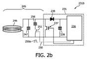
図2bは、本発明の第2実施形態に従うRFID装置231bを示す。RFID装置231bは、先と同じく、RFIDチップ235及びRF通信インターフェース245を有する。RFIDチップ235は、補助インターフェースが設けられていない点を除いては、図2aに示されている第1実施形態のRFIDチップと同じである。通信インターフェース245は、制御コマンドによるスイッチング素子251の作動の後に、コンデンサ256が発振回路から切り離されるように変更されている。発振回路は、最初に、アンテナ素子246、コンデンサ247及びコンデンサ256を有する。コンデンサ256の分離により発振回路の共振周波数は有意に変化する。これにより、通信インターフェース245の動作周波数は変更される。コンデンサ247及び256のキャパシタンスは、コンデンサ256の分離後に通信インターフェース245及びそれと共にRFID装置231b全体がもはや標準RFID読取器(図2bに図示せず。)と通信することができないような値を有する。しかし、RFID装置231bの第2の動作状態の動作周波数は、RFID装置231bと図示されていない読出用RFID装置との間の無線通信が可能であるように選択される。 FIG. 2b shows an
第2の動作状態の動作周波数及び/又はRF送信電力は、近距離通信のみが可能であるように選択され得ることが言及されるべきである。従って、切断されているRFID装置231bから読出用RFID装置へのデータ取り出しを可能にするために、読出用RFID装置は、切断されているRFID装置231bの通信インターフェース245の直ぐ近くに配置されるべきである。読出用RFID装置の配置に関するこのような近距離状態は、認められていない者に対する通信バリアを提供することを比較的簡単にする。従って、切断されているRFIDタグを有するユーザ持ち運びのアイテムのプライバシーは、簡単であるが有効な方法で保たれ得る。 It should be mentioned that the operating frequency and / or RF transmit power of the second operating state can be selected such that only short-range communication is possible. Therefore, in order to be able to retrieve data from the disconnected
図2cは、本発明の第3実施形態に従うRFID装置231cを示す。RFID装置231cは、RFIDチップ235及びRF通信インターフェース245を有する。RFIDチップ235は、図2bに示されている第2実施形態に従うRFIDチップと同じである。通信インターフェース245は、制御コマンド250aによる全部で4つのスイッチング素子251、252、253及び254の同時作動によって第1の動作状態から第2の動作状態へと切り換えられ得る。それによって、制御コマンド250aは、アンテナ素子246がコンデンサ247と共にRFID装置231cのRFIDチップ235から完全に切り離されるように、スイッチング素子251及び252を開く。同時に、制御コマンド250aは、コンデンサ258がRFIDチップ235へ接続されるようにスイッチング素子253及び254を選択する。これは、第2の動作状態でRFID装置231cと図示されていない読出用RFID装置との間の通信が、第1の動作状態での誘導結合と対照的に、コンデンサ258を介する無線容量結合によってのみ可能であることを意味する。 FIG. 2c shows an
容量結合にとって通常、空間的な補償範囲は誘導結合に比べてずっと小さいので、容量結合を介してのみ可能であるデータ取り出しは、自動的に、改善されたプライバシーに寄与する。これは、読出用RFID装置がRFID装置231cに近接して配置される必要があることから有効である。RFID装置231cは、変形されている切断コマンド250aによって第2の動作状態に移っている。 Since the spatial compensation range is usually much smaller for capacitive coupling compared to inductive coupling, data retrieval that is possible only via capacitive coupling automatically contributes to improved privacy. This is effective because the reading RFID device needs to be arranged close to the
図3は、RFID装置331と読出用RFID装置370との間の通信を復活させるために、切断されているRFID装置331での読出用RFID装置370の取付を示す。RFID装置331は、図2aに示されるRFID231aと同様の方法で形成されている。従って、RFID装置331は、主要通信インターフェース345及び補助通信インターフェース340を有する。主要通信インターフェース345はアンテナ素子346を有する。アンテナ素子346は、RFID装置331の第1の動作状態で、RFID装置331と標準RFID読取器との間の通信のために使用される。アンテナ素子346は、スイッチング素子351を作動させることによって、RFID装置331のRFIDチップから不可逆に切り離され得る。 FIG. 3 shows the attachment of the
主要通信インターフェース345を無効にした後に、RFID装置331は第2の動作状態にある。RFID装置331と標準RFID読取器との間の通信はもはや可能でない。しかし、上述されたように、RFID装置331と専用の読出用RFID装置370との間の通信は、補助通信インターフェース340を利用することによって可能である。補助通信インターフェース340は、2つの外部ガルバニック接触、すなわち、第1のガルバニック接触341及び第2のガルバニック接触342を有する。補助通信インターフェース340は、読出用RFID装置370の専用通信インターフェース380へ接続されるよう構成される。専用通信インターフェース380は、2つのガルバニック接触、すなわち、第1のガルバニック接触381及び第2のガルバニック接触382を有する。これらのガルバニック接触381及び382の間隔及び形状は、夫々、ガルバニック接触341及び342の間隔及び形状に対応する。 After disabling the
RFID装置331に対して読出用RFID装置370をどこに位置付けるべきかをユーザに示すために、RFID装置331はインジケータ361を設けられている。インジケータ361は、RFID装置331へ接触されるべき読出用RFID装置370の位置及び方向の両方をユーザに明示するのに適した様々な形状及び形態を取ることができる。 The
読出用RFID装置370から特別の読出装置(図示せず。)への更なるデータ送信を可能にするために、読出用RFID装置370は、アンテナ素子386を有する通信インターフェースを設けられている。読出用RFID装置370の計算能力に依存して、読出用RFID装置370と特別の読出装置との間のデータ接続は、符号化及び暗号化のための既知のプロシージャを用いることによって確立され得る。従って、データ取り出しのプライバシーは、切断されているRFID装置331と読出用RFID装置370との間のガルバニック接続のために、切断されているRFID装置331に記憶されているデータが読出用RFID装置370へ送信されるところの最初のステップでのみ保たれない。データ取り出しのプライバシーは、また、データが特別の読出装置へ送信されるところの第2のステップでは保たれる。 In order to allow further data transmission from the
RFID装置又はRFIDタグの記載される拡張された機能は、例えば、家庭用電気製品がRFID読取器を装備されることが考えられる未来の家庭で応用を有する。このようにして、自身のプライバシーについて心配しており且つ自身が持ち運んでいる物によって追跡されたくないユーザは、自身が購入するつもりである製品に埋め込まれているRFIDタグが無効にされることを売却完了時に要求する。従って、RFIDタグに記憶されている情報は、標準のRFID読取器を用いて認められていない者によって取り出され得ない。ユーザは、自身の家に到着すると、切断されたRFID装置の機能を原則的に復活させる物に、付随する読出用RFIDタグを置く。同時に、ユーザは、付随する読出用RFIDタグが、場合によっては安全な暗号化プロトコルを用いて、プライバシー保全方式でRFID読取器と相互作用するよう設計されているので、情報が漏れないことを確信する。かかる暗号化プロトコルは、元のRFIDタグによっては利用可能又は可能でない。元のRFIDタグは、費用の関係上受動的なタグである。 The described extended functionality of an RFID device or RFID tag has application in future homes where, for example, home appliances could be equipped with an RFID reader. In this way, users who are worried about their privacy and do not want to be tracked by things they carry will ensure that the RFID tags embedded in the products they intend to purchase are disabled. Request when the sale is complete. Thus, information stored in the RFID tag cannot be retrieved by an unauthorized person using a standard RFID reader. When the user arrives at his / her home, the user places an accompanying RFID tag for reading on the object that in principle restores the function of the disconnected RFID device. At the same time, the user is confident that no information will leak because the accompanying read RFID tag is designed to interact with the RFID reader in a privacy-preserving manner, possibly using a secure encryption protocol. To do. Such an encryption protocol may or may not be available depending on the original RFID tag. The original RFID tag is a passive tag for cost reasons.
留意すべきは、語「有する(comprising)」は他の要素又はステップを除外せず、「1つの(a,an)」は複数個を除外しない点である。また、異なる実施形態に関連して記載される要素は組み合わされ得る。また、留意すべきは、特許請求の範囲における参照符号は特許請求の範囲の適用範囲を限定するよう解釈されるべきではない点である。 Note that the word “comprising” does not exclude other elements or steps, and “a, an” does not exclude a plurality. Also, the elements described in connection with different embodiments may be combined. It should also be noted that reference signs in the claims should not be construed as limiting the scope of the claims.
100 RFIDシステム
110 RFID読取器
115 電子回路
116 振幅偏移キーイング変調器/ASK変調器
116a 駆動信号
120 発振回路
121 信号入力ユニット
122 抵抗
123 コンデンサ
124 アンテナ
125 帯域通過フィルタ
126 増幅器
127 復調器
129 出力データ
130 標準RFID装置/標準RFIDタグ
135 RFIDチップ
136 RFID回路、データメモリ
136a バイナリ変調コード
137 トランジスタ結合素子
138 ダイオード
139 コンデンサ
145 通信インターフェース
146 アンテナ素子
147 コンデンサ
231a RFID装置/RFIDタグ
231b RFID装置/RFIDタグ
231c RFID装置/RFIDタグ
235 RFIDチップ
236 RFID回路、データメモリ
237 トランジスタ結合素子
238 ダイオード
239 コンデンサ
240 更なる通信インターフェース
241 外部ガルバニック接触
242 外部ガルバニック接触
245 通信インターフェース
246 アンテナ素子
247 コンデンサ
250 コマンドライン
250a 制御コマンド/切断コマンド
251 スイッチング素子
252 スイッチング素子
253 スイッチング素子
254 スイッチング素子
256 コンデンサ
258 コンデンサ
331 RFID装置/RFIDタグ
340 補助通信インターフェース
341 外部ガルバニック接触
342 外部ガルバニック接触
345 主要通信インターフェース
346 アンテナ素子
351 スイッチング素子
361 インジケータ
370 読出用RFID装置/読出用RFIDタグ
380 更なる通信インターフェース
381 外部ガルバニック接触
382 外部ガルバニック接触
385 通信インターフェース
386 アンテナ素子100
Claims (20)
Translated fromJapanese前記データメモリへ結合され、第1の動作構造及び第2の動作構造を有し、制御コマンドを受け取ることによって前記第1の動作構造から前記第2の動作構造へと不可逆に切り換えられ得る電子回路配置と、
前記電子回路配置へ結合される通信インターフェースと
を有し、
前記第1の動作構造で、前記通信インターフェースを介して標準RFID読取器と通信するよう構成され、
前記第2の動作構造で、前記標準RFID読取器との通信は無効にされ、読出用RFID装置と通信するよう構成されるRFID装置。Data memory,
An electronic circuit coupled to the data memory, having a first operating structure and a second operating structure and capable of being irreversibly switched from the first operating structure to the second operating structure by receiving a control command Arrangement,
A communication interface coupled to the electronic circuit arrangement;
Configured to communicate with a standard RFID reader via the communication interface in the first operational structure;
An RFID device configured to communicate with a reading RFID device, wherein communication with the standard RFID reader is disabled in the second operational structure.
当該RFID装置と前記標準RFID読取器との間の誘導結合から、
当該RFID装置と前記読出用RFID装置との間の容量結合へ
と変化させるよう構成される、請求項8記載のRFID装置。The switching element is for the RFID device coupling mode, in particular,
From inductive coupling between the RFID device and the standard RFID reader,
9. The RFID device of claim 8, configured to change to capacitive coupling between the RFID device and the reading RFID device.
請求項11記載の読出用RFID装置と、
前記読出用RFID装置と通信するよう構成される読取器と
を有するRFIDシステム。An RFID device according to claim 1;
An RFID device for reading according to claim 11,
A reader system configured to communicate with the reading RFID device.
情報関連データを前記RFID装置から請求項11記載の読出用RFID装置へ送信するステップと、
前記データを前記読出用RFID装置から読取器へ送信するステップと
を有する方法。A method for extracting information stored in an RFID device according to claim 1,
Transmitting information related data from the RFID device to the reading RFID device of claim 11;
Transmitting the data from the reading RFID device to a reader.
Applications Claiming Priority (2)
| Application Number | Priority Date | Filing Date | Title |
|---|---|---|---|
| EP06121120 | 2006-09-22 | ||
| PCT/IB2007/053797WO2008035296A2 (en) | 2006-09-22 | 2007-09-19 | Extended functionality of rfid devices |
Publications (1)
| Publication Number | Publication Date |
|---|---|
| JP2010504580Atrue JP2010504580A (en) | 2010-02-12 |
Family
ID=39200933
Family Applications (1)
| Application Number | Title | Priority Date | Filing Date |
|---|---|---|---|
| JP2009528845APendingJP2010504580A (en) | 2006-09-22 | 2007-09-19 | RFID device expansion function |
Country Status (4)
| Country | Link |
|---|---|
| US (1) | US8502669B2 (en) |
| JP (1) | JP2010504580A (en) |
| CN (1) | CN101573717A (en) |
| WO (1) | WO2008035296A2 (en) |
Cited By (2)
| Publication number | Priority date | Publication date | Assignee | Title |
|---|---|---|---|---|
| KR101295344B1 (en)* | 2011-07-04 | 2013-08-23 | 주식회사 씨티네트웍스 | Wireless Communication Module of Optical Cable Numbering System |
| JP7649085B1 (en)* | 2024-12-24 | 2025-03-19 | 株式会社Lozi | Information processing system, information processing method, and program |
Families Citing this family (23)
| Publication number | Priority date | Publication date | Assignee | Title |
|---|---|---|---|---|
| US7162035B1 (en) | 2000-05-24 | 2007-01-09 | Tracer Detection Technology Corp. | Authentication method and system |
| US8171567B1 (en) | 2002-09-04 | 2012-05-01 | Tracer Detection Technology Corp. | Authentication method and system |
| JP2010504580A (en)* | 2006-09-22 | 2010-02-12 | コーニンクレッカ フィリップス エレクトロニクス エヌ ヴィ | RFID device expansion function |
| US20090117847A1 (en)* | 2007-11-01 | 2009-05-07 | Sirit Technologies Inc. | Passively transferring radio frequency signals |
| US7995196B1 (en) | 2008-04-23 | 2011-08-09 | Tracer Detection Technology Corp. | Authentication method and system |
| JP5455753B2 (en)* | 2009-04-06 | 2014-03-26 | 株式会社半導体エネルギー研究所 | IC card |
| US8668145B2 (en)* | 2009-04-21 | 2014-03-11 | Technology Innovators Inc. | Automatic touch identification system and method thereof |
| CN101556656B (en)* | 2009-05-15 | 2011-05-04 | 深圳市远望谷信息技术股份有限公司 | Passive magnetic induction electronic tag |
| EP2264642B1 (en)* | 2009-06-02 | 2014-02-26 | Vodafone Holding GmbH | Data exchange with a man-machine-device using short range radio communication |
| TW201127079A (en)* | 2010-01-22 | 2011-08-01 | Wistron Corp | Audio broadcasting device and portable device using the same |
| CN102143415A (en)* | 2010-01-29 | 2011-08-03 | 纬创资通股份有限公司 | Speaker Devices and Handheld Devices |
| EP2432074A1 (en)* | 2010-09-21 | 2012-03-21 | Printechnologics GmbH | Component with at least one UHF dipole aerial |
| US8798688B2 (en) | 2011-01-20 | 2014-08-05 | Clifford August | Systems and methods for transmitting data using near field communications |
| US8917161B2 (en) | 2011-10-21 | 2014-12-23 | Clifford J. August | Systems and methods for transmitting data using near field communications |
| US20140118114A1 (en)* | 2012-10-30 | 2014-05-01 | Quantitative Sampling Technologies, LLC | Bridge board for enhancing functionality of a data acquisition device |
| US9495851B1 (en)* | 2014-11-25 | 2016-11-15 | Amazon Technologies, Inc. | Tag-based product monitoring and evaluation |
| US9668034B2 (en)* | 2015-02-13 | 2017-05-30 | Goodrich Corporation | Systems and methods for communicating data of a power transmission line |
| US9913989B2 (en)* | 2016-04-28 | 2018-03-13 | Medtronic, Inc. | Managing telemetry communication modes of an implantable device |
| CN106447016A (en)* | 2016-11-29 | 2017-02-22 | 珠海南方集成电路设计服务中心 | Protection method and system for enabling or disabling of RFID in passive state |
| US11055657B2 (en) | 2017-03-02 | 2021-07-06 | Micron Technology, Inc. | Methods and apparatuses for determining real-time location information of RFID devices |
| US10075392B1 (en)* | 2017-03-02 | 2018-09-11 | Micron Technology, Inc. | Methods and apparatuses for processing multiple communications signals with a single integrated circuit chip |
| CN113993562A (en)* | 2019-06-13 | 2022-01-28 | 赛诺菲 | Electronically controlled capture system for drug delivery systems |
| CN113420573B (en)* | 2020-09-23 | 2023-12-15 | 阿里巴巴集团控股有限公司 | Phased array system and phase setting method |
Family Cites Families (57)
| Publication number | Priority date | Publication date | Assignee | Title |
|---|---|---|---|---|
| DE19503607A1 (en) | 1995-02-03 | 1996-08-08 | Angewandte Digital Elektronik | Chip cards for displaying different card information |
| JP3916291B2 (en)* | 1997-03-28 | 2007-05-16 | ローム株式会社 | Information communication equipment |
| WO2000034605A1 (en) | 1998-12-08 | 2000-06-15 | Microchip Technology Incorporated | A radio frequency identification (rfid) security device |
| US7005985B1 (en) | 1999-07-20 | 2006-02-28 | Axcess, Inc. | Radio frequency identification system and method |
| US6564999B1 (en)* | 1999-09-09 | 2003-05-20 | Shurflo Pump Manufacturing Company, Inc. | Food containers with transponders |
| DE10055602A1 (en)* | 1999-12-30 | 2001-07-12 | Ibm | Exit control system for supermarket or department store, produces receipt based on contactlessly received information and updates payment status |
| ATE338308T1 (en)* | 2000-06-12 | 2006-09-15 | Supersensor Proprietary Ltd | READING PROTOCOL FOR LABELS IN AN ELECTRONIC IDENTIFICATION SYSTEM |
| DE10132031A1 (en)* | 2001-07-03 | 2003-01-23 | Texas Instruments Deutschland | Process for enabling authenticated access of an individual to a protected area and security system for carrying out the process |
| WO2003098528A2 (en)* | 2002-05-16 | 2003-11-27 | Ruth Raphaeli | Method and system for distance determination of rf tags |
| WO2004053721A1 (en)* | 2002-12-10 | 2004-06-24 | Shalom Wertsberger | Deactivation of radio frequency identification tags |
| US7532104B2 (en) | 2003-05-06 | 2009-05-12 | Rsa Security, Inc. | Low-complexity cryptographic techniques for use with radio frequency identification devices |
| US6970070B2 (en) | 2003-05-08 | 2005-11-29 | Rsa Security Inc. | Method and apparatus for selective blocking of radio frequency identification devices |
| US7152040B1 (en)* | 2003-05-27 | 2006-12-19 | Microsoft Corporation | Electronic shelf label |
| US7068169B2 (en)* | 2003-06-05 | 2006-06-27 | Motorola, Inc. | Use of a subcarrier in an organic semiconductor radio frequency identification system |
| US7446646B2 (en)* | 2003-06-30 | 2008-11-04 | Nokia Corporation | System and method for supporting multiple reader-tag configurations using multi-mode radio frequency tag |
| FR2860631B1 (en)* | 2003-10-02 | 2007-06-15 | Alessandro Manneschi | DETECTOR OF UNAUTHORIZED OBJECTS IN A PROTECTED ACCESS AREA |
| CN101189623B (en)* | 2003-10-29 | 2010-06-02 | Nxp股份有限公司 | Communication partner appliance with automatic send mode activation and method therefor |
| US7716160B2 (en)* | 2003-11-07 | 2010-05-11 | Alien Technology Corporation | Methods and apparatuses to identify devices |
| GB0327290D0 (en)* | 2003-11-24 | 2003-12-24 | Rolls Royce Plc | Method and system for assisting the passage of an entity through successive zones to a destination |
| DE10356284A1 (en) | 2003-11-28 | 2005-07-07 | Skidata Ag | disk |
| EP1538556A1 (en) | 2003-12-02 | 2005-06-08 | Shalom Wertsberger | Radio frequency identification tags |
| US7245213B1 (en)* | 2004-05-24 | 2007-07-17 | Impinj, Inc. | RFID readers and RFID tags exchanging encrypted password |
| US7920050B2 (en) | 2004-07-29 | 2011-04-05 | Emc Corporation | Proxy device for enhanced privacy in an RFID system |
| US7158033B2 (en)* | 2004-09-01 | 2007-01-02 | Avery Dennison Corporation | RFID device with combined reactive coupler |
| US7893816B1 (en)* | 2004-12-10 | 2011-02-22 | Ncr Corporation | High sensitivity radio frequency identification tag |
| US7474211B2 (en)* | 2005-02-22 | 2009-01-06 | Bradley Allen Kramer | System and method for killing a RFID tag |
| US7515051B2 (en)* | 2005-02-25 | 2009-04-07 | Datalogic Mobile, Inc. | RFID antenna system having reduced orientation sensitivity |
| US8120492B2 (en)* | 2005-02-25 | 2012-02-21 | Tom Ahlkvist Scharfeld | Blister package with integrated electronic tag and method of manufacture |
| KR100672058B1 (en)* | 2005-03-02 | 2007-01-22 | 삼성전자주식회사 | RDF readers and RDF tags that use the BHF band and how they work |
| US20060220795A1 (en)* | 2005-03-22 | 2006-10-05 | Supply Focus | Method and apparatus for tag with adjustable read distance |
| KR100705325B1 (en)* | 2005-03-30 | 2007-04-09 | 삼성전자주식회사 | RF-ID tag reading system using password and its method |
| GB0507285D0 (en)* | 2005-04-11 | 2005-05-18 | Innovision Res & Tech Plc | Nfc enabled high-speed data |
| KR100667344B1 (en)* | 2005-04-15 | 2007-01-15 | 삼성전자주식회사 | RDF tags and RDF readers to prevent collisions and how to operate them |
| US20070046467A1 (en)* | 2005-08-31 | 2007-03-01 | Sayan Chakraborty | System and method for RFID reader to reader communication |
| CN101176361A (en)* | 2005-05-16 | 2008-05-07 | Lg电子株式会社 | Radio frequency identification data processing system |
| US7280045B2 (en)* | 2005-06-14 | 2007-10-09 | Nokia Corporation | Machine-readable tag, selectable extension antennas for use therewith, and display structure having such tag |
| WO2007008916A2 (en)* | 2005-07-11 | 2007-01-18 | Kestrel Wireless Inc. | A radio frequency activated integrated circuit and method of disabling the same |
| JP4817768B2 (en)* | 2005-09-07 | 2011-11-16 | 富士通株式会社 | Information access system and active contactless information storage device |
| KR100738329B1 (en)* | 2005-09-23 | 2007-07-12 | 한국전자통신연구원 | Information security method between RFID reader and tag and RFID reader and tag for it |
| US7969282B2 (en)* | 2005-12-21 | 2011-06-28 | Symbol Technologies, Inc. | Optimized operation of a dense reader system |
| US7741967B2 (en)* | 2006-02-13 | 2010-06-22 | Xerox Corporation | Locating system for items having RFID tags |
| US20070236334A1 (en)* | 2006-03-31 | 2007-10-11 | Borovoy Richard D | Enhancing face-to-face communication |
| US20070241906A1 (en)* | 2006-03-31 | 2007-10-18 | Symbol Technologies, Inc. | Methods and apparatus for an RFID system with multi-antenna zones |
| US7545274B2 (en)* | 2006-04-10 | 2009-06-09 | The Boeing Company | RFID data management system |
| US20080001724A1 (en)* | 2006-06-28 | 2008-01-03 | Symbol Technologies, Inc. | Using read lock capability for secure RFID authentication |
| US7385510B2 (en)* | 2006-06-30 | 2008-06-10 | International Business Machines Corporation | Container manifest integrity maintenance system and method |
| US7734994B2 (en)* | 2006-07-20 | 2010-06-08 | Broadcom Company | RFID decoding subsystem with pre-decode module |
| US20080034183A1 (en)* | 2006-08-07 | 2008-02-07 | Symbol Technologies, Inc. | Protecting Critical Pointer Value Updates To Non-Volatile Memory Under Marginal Write Conditions |
| US8570172B2 (en)* | 2006-09-08 | 2013-10-29 | Intelleflex Corporation | RFID system with distributed transmitters |
| JP2010504580A (en)* | 2006-09-22 | 2010-02-12 | コーニンクレッカ フィリップス エレクトロニクス エヌ ヴィ | RFID device expansion function |
| US7791453B2 (en)* | 2006-11-21 | 2010-09-07 | International Business Machines Corporation | System and method for varying response amplitude of radio transponders |
| US7679514B2 (en)* | 2007-03-30 | 2010-03-16 | Broadcom Corporation | Multi-mode RFID tag architecture |
| US20090033493A1 (en)* | 2007-07-31 | 2009-02-05 | Symbol Technologies, Inc. | Method, System and Apparatus for Writing Common Information to a Plurality of Radio Frequency Identification (RFID) Tags |
| EP3002820B1 (en)* | 2007-08-02 | 2020-06-03 | University of Pittsburgh - Of the Commonwealth System of Higher Education | Wireless systems having multiple electronic devices and employing simplified fabrication and matching, and associated methods |
| US7843347B2 (en)* | 2008-01-30 | 2010-11-30 | Intermac Ip Corp. | Near-field and far-field antenna-assembly and devices having same |
| JP4661952B2 (en)* | 2008-12-02 | 2011-03-30 | ソニー株式会社 | COMMUNICATION DEVICE AND COMMUNICATION METHOD, COMPUTER PROGRAM, AND COMMUNICATION SYSTEM |
| JP5217982B2 (en)* | 2008-12-04 | 2013-06-19 | ソニー株式会社 | Information processing apparatus and method, and program |
- 2007
- 2007-09-19JPJP2009528845Apatent/JP2010504580A/enactivePending
- 2007-09-19WOPCT/IB2007/053797patent/WO2008035296A2/enactiveApplication Filing
- 2007-09-19USUS12/441,582patent/US8502669B2/enactiveActive
- 2007-09-19CNCNA2007800352297Apatent/CN101573717A/enactivePending
Cited By (2)
| Publication number | Priority date | Publication date | Assignee | Title |
|---|---|---|---|---|
| KR101295344B1 (en)* | 2011-07-04 | 2013-08-23 | 주식회사 씨티네트웍스 | Wireless Communication Module of Optical Cable Numbering System |
| JP7649085B1 (en)* | 2024-12-24 | 2025-03-19 | 株式会社Lozi | Information processing system, information processing method, and program |
Also Published As
| Publication number | Publication date |
|---|---|
| US20100026461A1 (en) | 2010-02-04 |
| CN101573717A (en) | 2009-11-04 |
| WO2008035296A3 (en) | 2009-06-25 |
| WO2008035296A2 (en) | 2008-03-27 |
| US8502669B2 (en) | 2013-08-06 |
Similar Documents
| Publication | Publication Date | Title |
|---|---|---|
| JP2010504580A (en) | RFID device expansion function | |
| US7460018B2 (en) | Communications system for an RFID tag having an inductive antenna device detachable or movable | |
| Phillips et al. | Security standards for the RFID market | |
| US9070066B1 (en) | RFID tags with inductively coupled antennas | |
| US8570172B2 (en) | RFID system with distributed transmitters | |
| US10650201B1 (en) | RFID tags with port-dependent functionality | |
| US8115590B1 (en) | RFID readers limiting theft of confidential information | |
| US20090033464A1 (en) | Transponder with access protection and method for access to the transponder | |
| CN101467157A (en) | Method, RFID reader, RFID tag and RFID system for secure communication | |
| WO2007145907A2 (en) | Rfid-based security systems and methods | |
| CN114600121A (en) | RFID IC with Privacy Mode | |
| CN111788581B (en) | Apparatus and method for enabling multiple forms of RFID technology to interact to provide additional information, security, and performance | |
| JP2011521599A (en) | A system that gives a fixed identification number for a transponder while protecting privacy and preventing tracking | |
| US8441342B2 (en) | Pseudo-random authentification code altering scheme for a transponder and a base station | |
| Park | An IoT application service using mobile RFID technology | |
| Kulkarni et al. | RFID security issues & challenges | |
| Xiao et al. | RFID technology, security vulnerabilities, and countermeasures | |
| CN102567697B (en) | Reader, RFID label tag and read method thereof | |
| US20070205864A1 (en) | Secure radio frequency identification system | |
| CN204204002U (en) | RFID components and RFID tags | |
| Guizani | Security applications challenges of RFID technology and possible countermeasures | |
| KR100819048B1 (en) | RF tag attached article Personalized electronic tag and personal privacy protection device and method using the same | |
| US20110215907A1 (en) | Radio frequency identifcation (rfid) tag and operation method thereof, and system and method for controlling network access based on mobile rfid | |
| JP2005100205A (en) | Non-contact IC tag data encryption / decryption method and system, and non-contact IC tag | |
| Pathak et al. | Applications of RFID and a software framework for facilitating its integration in mobile phones |