JP2010503479A - Vascular treatment instrument - Google Patents
Vascular treatment instrumentDownload PDFInfo
- Publication number
- JP2010503479A JP2010503479AJP2009528466AJP2009528466AJP2010503479AJP 2010503479 AJP2010503479 AJP 2010503479AJP 2009528466 AJP2009528466 AJP 2009528466AJP 2009528466 AJP2009528466 AJP 2009528466AJP 2010503479 AJP2010503479 AJP 2010503479A
- Authority
- JP
- Japan
- Prior art keywords
- segment
- handle
- wire
- distal end
- cartridge
- Prior art date
- Legal status (The legal status is an assumption and is not a legal conclusion. Google has not performed a legal analysis and makes no representation as to the accuracy of the status listed.)
- Granted
Links
Images


Classifications
- A—HUMAN NECESSITIES
- A61—MEDICAL OR VETERINARY SCIENCE; HYGIENE
- A61B—DIAGNOSIS; SURGERY; IDENTIFICATION
- A61B17/00—Surgical instruments, devices or methods
- A61B17/32—Surgical cutting instruments
- A61B17/3205—Excision instruments
- A61B17/3207—Atherectomy devices working by cutting or abrading; Similar devices specially adapted for non-vascular obstructions
- A61B17/320758—Atherectomy devices working by cutting or abrading; Similar devices specially adapted for non-vascular obstructions with a rotating cutting instrument, e.g. motor driven
- A—HUMAN NECESSITIES
- A61—MEDICAL OR VETERINARY SCIENCE; HYGIENE
- A61B—DIAGNOSIS; SURGERY; IDENTIFICATION
- A61B17/00—Surgical instruments, devices or methods
- A61B17/00008—Vein tendon strippers
- A—HUMAN NECESSITIES
- A61—MEDICAL OR VETERINARY SCIENCE; HYGIENE
- A61B—DIAGNOSIS; SURGERY; IDENTIFICATION
- A61B17/00—Surgical instruments, devices or methods
- A61B2017/00367—Details of actuation of instruments, e.g. relations between pushing buttons, or the like, and activation of the tool, working tip, or the like
- A61B2017/00398—Details of actuation of instruments, e.g. relations between pushing buttons, or the like, and activation of the tool, working tip, or the like using powered actuators, e.g. stepper motors, solenoids
- A—HUMAN NECESSITIES
- A61—MEDICAL OR VETERINARY SCIENCE; HYGIENE
- A61B—DIAGNOSIS; SURGERY; IDENTIFICATION
- A61B17/00—Surgical instruments, devices or methods
- A61B2017/0046—Surgical instruments, devices or methods with a releasable handle; with handle and operating part separable
- A—HUMAN NECESSITIES
- A61—MEDICAL OR VETERINARY SCIENCE; HYGIENE
- A61B—DIAGNOSIS; SURGERY; IDENTIFICATION
- A61B17/00—Surgical instruments, devices or methods
- A61B2017/00477—Coupling
- A—HUMAN NECESSITIES
- A61—MEDICAL OR VETERINARY SCIENCE; HYGIENE
- A61B—DIAGNOSIS; SURGERY; IDENTIFICATION
- A61B17/00—Surgical instruments, devices or methods
- A61B2017/00743—Type of operation; Specification of treatment sites
- A61B2017/00778—Operations on blood vessels
- A—HUMAN NECESSITIES
- A61—MEDICAL OR VETERINARY SCIENCE; HYGIENE
- A61B—DIAGNOSIS; SURGERY; IDENTIFICATION
- A61B17/00—Surgical instruments, devices or methods
- A61B17/22—Implements for squeezing-off ulcers or the like on inner organs of the body; Implements for scraping-out cavities of body organs, e.g. bones; for invasive removal or destruction of calculus using mechanical vibrations; for removing obstructions in blood vessels, not otherwise provided for
- A61B2017/22082—Implements for squeezing-off ulcers or the like on inner organs of the body; Implements for scraping-out cavities of body organs, e.g. bones; for invasive removal or destruction of calculus using mechanical vibrations; for removing obstructions in blood vessels, not otherwise provided for after introduction of a substance
- A61B2017/22084—Implements for squeezing-off ulcers or the like on inner organs of the body; Implements for scraping-out cavities of body organs, e.g. bones; for invasive removal or destruction of calculus using mechanical vibrations; for removing obstructions in blood vessels, not otherwise provided for after introduction of a substance stone- or thrombus-dissolving
Landscapes
- Health & Medical Sciences (AREA)
- Surgery (AREA)
- Life Sciences & Earth Sciences (AREA)
- Biomedical Technology (AREA)
- Nuclear Medicine, Radiotherapy & Molecular Imaging (AREA)
- Engineering & Computer Science (AREA)
- Vascular Medicine (AREA)
- Heart & Thoracic Surgery (AREA)
- Medical Informatics (AREA)
- Molecular Biology (AREA)
- Animal Behavior & Ethology (AREA)
- General Health & Medical Sciences (AREA)
- Public Health (AREA)
- Veterinary Medicine (AREA)
- Surgical Instruments (AREA)
Abstract
Translated fromJapaneseDescription
Translated fromJapanese関連出願の相互参照
本願は、2006年9月13日出願の米国仮特許出願第60/825,529号明細書、及び2007年5月4日出願の米国仮特許出願第60/916,110号明細書の利益を主張するものであり、双方の文献とも本明細書によって参照により本明細書に援用される。This application is related to US Provisional Patent Application No. 60 / 825,529, filed September 13, 2006, and US Provisional Patent Application No. 60 / 916,110, filed May 4, 2007. The claims of the specification are claimed and both documents are hereby incorporated by reference.
血管治療用器具は、(1)モータ、トリガ、及び雄型連結具を有するハンドルと、(2)ハンドルと係合可能で、雌型連結具、ワイヤ、及びシースを有し、シースを固定しているカートリッジとを備え得る。雌型連結具が雄型連結具と係合していないときは、シースがワイヤの遠位端を被覆し得るため、器具を患者の血管系に安全に前進させることができ、雌型連結具が雄型連結具により係合されると、ワイヤの遠位端がシースから露出して使用できる。 The vascular treatment device includes (1) a handle having a motor, a trigger, and a male connector, and (2) an engagable handle, a female connector, a wire, and a sheath, and fixing the sheath. A cartridge may be provided. When the female connector is not engaged with the male connector, the sheath can cover the distal end of the wire so that the instrument can be safely advanced into the patient's vasculature, and the female connector Can be used with the distal end of the wire exposed from the sheath.
血管治療用器具は、数ある用途の中でも特に、血管、例えば静脈瘤の切除、及び凝血塊を浸軟して血栓溶解薬を注入することによる血栓症の治療に用いられ得る。血管治療用器具は回転可能なワイヤを備え、このワイヤは血管の切除に適したサイズ及び形状であり、ハンドルと係合可能なカートリッジに連結される。従ってワイヤはハンドルのモータと間接的に係合され得るものであり、モータの電源が入るとワイヤが回転する。器具が静脈瘤の治療に用いられるときは、この回転するワイヤが血管に動揺を与えて血管が攣縮する状態の血管痙攣を生じさせ、血管壁を損傷させて硬化を促進し得る。血栓除去術においては、ワイヤは血管壁を損傷させることなく凝血塊を浸軟し得る。 Vascular treatment devices can be used, among other applications, for the removal of blood vessels, such as varicose veins, and for the treatment of thrombosis by macerating a clot and injecting a thrombolytic agent. The vascular treatment instrument comprises a rotatable wire, which is sized and shaped suitable for resection of a blood vessel and is connected to a cartridge engageable with a handle. Therefore, the wire can be indirectly engaged with the motor of the handle, and the wire rotates when the motor is turned on. When the device is used to treat varicose veins, the rotating wire can cause vascular spasms that sway the blood vessels and cause the blood vessels to contract, damage the blood vessel walls and promote hardening. In thrombectomy, the wire can macerate the clot without damaging the vessel wall.
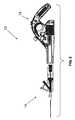
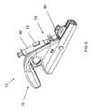
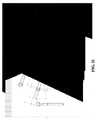
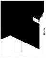
図1は、ハンドル12とカートリッジ14とを有する血管治療用器具10のアセンブリの実施形態を示す。カートリッジ14は、図示されるとおり、ハンドル12と互いの構成部品を嵌め合うことにより係合するようなサイズ及び形状とされ得る。ハンドル12の実施形態は、図3にさらに詳細に示される。ハンドルは収容部29を画成でき、その中には雄型連結具30が、カートリッジ14とハンドル12との係合時にカートリッジ14の雌型連結具40を受け止めるよう位置決めされる。ハンドル12は、モータ22、トリガ26、及び雄型連結具30を備え得る。雄型連結具30はモータ22に接続され、モータが作動すると雄型連結具が回転駆動するようにされ得る。ポテンショメータ24がモータ22と電気的に連結され、モータの速度を制御し得る。トリガ26はハンドルに装着され、モータを電源と電気的に連結しない第1の状態と、モータを電源と連結する第2の状態との間を切り換え可能であり得る。 FIG. 1 illustrates an embodiment of an assembly of a
ハンドル12はまた、ワイヤ32によりモータ22と接続された電源20及びマイクロスイッチ28も備え得る。マイクロスイッチ28はトリガ26とモータ22とを接続する電気回路に間置され得る。マイクロスイッチが付勢されて開放位置になると、トリガとモータとの間の回路が開放され得る。カートリッジ14がハンドル12に係合されると、カートリッジがマイクロスイッチを押すためマイクロスイッチが閉鎖状態に切り換わり、それによりトリガ26とモータ22とを接続する電気回路が閉じられる。例えば、マイクロスイッチは2つの接点を備えてもよく、一方の接点には導体が取り付けられ、これはマイクロスイッチが開放状態のときは第2の接点から切り離されている。一実施形態において、導体としては金属ストリップを挙げることができ、これはハンドルとの係合に際しカートリッジを摺動させるチャネル内に吊り下げられる。カートリッジがハンドルに係合されると、カートリッジが金属ストリップをチャネルから押し出してマイクロスイッチの第2の接点と接続させる。かかる構成から得られる利点の1つは、器具の使用準備が整わないうちに、すなわち、カートリッジ14がハンドル12と完全に係合される前に、使用者が不注意にトリガを押して器具を作動させる可能性がないことであり得る。 The
ハンドル12はまた、図3に示されるとおりスイッチ16も備え得る。スイッチ16によりカートリッジ14をハンドル12に入れて固定することができる。スイッチはグリップ15を備えてもよく、それにより使用者は指でスイッチを操作できる。スイッチはまたゲート17も備え、これはゲートの位置に応じてカートリッジの遮断又は係止を交互に行う。例えば、使用者は親指をグリップ15に置き、スイッチ16をハンドルグリップ25から離れる方に押すことにより、ゲート17がチャネルに配置されているためカートリッジ12とハンドル14との係合が妨げられている第1の位置から、ゲート17がチャネルから取り払われるためカートリッジとハンドルとの係合が可能となる第2の位置へと、スイッチ16を切り換え得る。付勢されたスイッチ16が解除されると、ゲート17はカートリッジの相補的な戻り止めに嵌合し、それによりカートリッジのハンドルとの係合の維持を補助し得る。 The
ゲート17は、ハンドルに接触しているスプリング23により第1の位置に付勢されていてもよい。使用者がスイッチ16をハンドルグリップ25から離れる方に押すと、スイッチ16がスプリングを押圧し、従って使用者がスイッチを解除すれば、復元力が生じてスイッチはその元の位置に押し戻される。 The
上述のとおり、ゲート17はさらに、カートリッジ14がハンドル12から外れないようにする第3の位置に切り換え可能であり得る。例えば、付勢されたスイッチ16が第2の位置からその元の位置に戻るとき、ゲート17がカートリッジ14により画成される戻り止め35(図4に図示)の中に送り込まれ、カートリッジがハンドルに係止され得る。 As described above, the
ハンドル12の1つ又は複数の部分が、中にトリガが少なくとも部分的に配置されるトリガリング18を画成してもよく、ハンドルは、ハンドルのトリガリングを画成する1つ又は複数の部分のみから支持されると、トリガリング18を中心にして平衡が保たれるよう構成される。このようにすると、使用者は、単にハンドルのトリガリング18を画成する部分を人差し指などの1本の指で支えるだけで、ハンドルの平衡を保ち得る。モータ22はハンドルのなかで最も重い構成要素であり得るため、モータ22は図3に示されるとおりトリガ26の下に位置決めすることで、トリガリングによってハンドルを支える指に対しモータ22から加えられる屈曲モーメントが低減され、従って使用者の被る疲労を低減し得る。 One or more portions of the
ハンドル12は2つの外側ケーシング部品を一緒に接合することにより形成され得る。 The
図1に図示されるカートリッジ14の実施形態が、図4にさらに詳細に示される。カートリッジ14は、雌型連結具40、ワイヤ33(破線で図示される)、及びシース32を備えてもよく、シース32はカートリッジ14に固定され、そこから延在する。ワイヤは雌型連結具40に固定されてもよく、例えば、ワイヤの近位先端は約90度屈曲させることでそのワイヤの屈曲端を収容するサイズ及び形状のチャネルの中に嵌め込み得る。止めねじが雌型連結具40に差し込まれてもよく、及び/又は然るべき接着剤を用いてワイヤを固定し、ワイヤが雌型連結具に対し回転しないようにしてもよい。 The embodiment of the
シース32はワイヤ33が通るルーメンを画成し得る。シース32の内径及び外径は様々であり得る。ある実施形態において、シースの内径は0.022インチ〜0.048インチの範囲であり得る。ある実施形態において、シース32の外径は0.025インチ〜0.051インチの範囲であり得る。シースの外径はまた、対応する内径の標準的な針と整合する範囲であってもよい。例えばシースは、0.0035インチ〜0.1060インチ、又は0.0160インチ〜0.0420インチ、又は0.0420インチ〜0.0630インチ、又は0.0115インチ〜0.0630インチの範囲の内径の標準的な針又は血管シースに挿入可能なサイズ及び形状とされ得る。シースの最大外径は0.035インチ未満として0.0039インチ未満の内径の静脈注射針又はカテーテル内にシースを挿入できるようにすることで、様々な医師が手技を行うことが可能となる。0.079インチ(6フレンチ、Fr)又は0.092インチ(7Fr)より大きい外径の針、カテーテル又は血管シースの挿入は、典型的には血管外科医又はインターベンショナル・ラジオロジストが行う必要がある。 The
シース32はまた、等間隔の外部標示を備えてもよく、それらの案内により使用者は器具10の挿入又は抜去速度をモニタし得る。 The
カートリッジに接続可能な容器を図示する一例示的実施形態は、図5に示されるとおり、シリンジ44、ストップコック46、及びプランジャ48を備え得る。シリンジ44はシース32の穴と流体連通しており、ワイヤ遠位端に物質、例えば、硬化剤(その例としては、ポリドカノール、テトラデシル硫酸ナトリウム、及び高張食塩水が挙げられる)、又は血栓溶解薬(その例としては、アルテプラーゼ(アクチバーゼ(Activase))、アニストレプラーゼ(エミナーゼ(Eminase))、ストレプトキナーゼ(ストレプターゼ(Streptase)、カビキナーゼ(Kabikinase))、ウロキナーゼ(アボキナーゼ(Abbokinase))、及び組織プラスミノーゲンアクチベータ(TPA)が挙げられる)などを放出し得る。このように、ワイヤによる物理的な動揺を薬物治療と相乗的に組み合わせることで、器具の有効性が高まり得る。 One exemplary embodiment illustrating a container connectable to the cartridge may comprise a
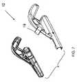
ハンドル12は、シリンジ44を支えるよう位置決めされた支持体19(図3に図示)を備え得る。支持体19は標準的なシリンジに適合するサイズ及び形状であってもよく、特に、注入される材料の容量及び/又は粘度が大きく、使用者が親指でシリンジに大きい圧力をかける必要がある場合に、注射中のシリンジの脱落を防ぎ得る。シリンジ44の取り付けられたカートリッジ14がハンドルに係合されるとき、シリンジ44は支持体19にスナップ嵌めされ得る。図1に示されるとおり、支持体はシリンジを包み込むように受ける2つのブラケットで形成され得る。図6及び7に図示される代替的実施形態は、シリンジの周りに部分的に巻き付く単一のフックで形成された支持体を備える。これらの実施形態により、器具は、使用者の随意に、及び/又は診療台上の患者の位置に応じて、右手でも左手でも使用可能となる。 The
ハンドル12及びシリンジ44は、使用者がトリガ26を手の人差し指で作動させると同時に、プランジャ48を同じ手の親指でシリンジの中に押し込むことのできるサイズ、形状、及び位置とされてもよく、それにより治療薬をシリンジからシースを通じて拡散させながらワイヤ33を回転させることができる。例えば、使用者はハンドルグリップ25を手掌の中心に位置決めし、中指、薬指、及び小指をハンドルグリップの周りに巻き付け、人差し指をトリガリング18の中に通すことによってハンドルを保持でき、必要に応じて親指を置いてプランジャを押し下げ、治療薬をシリンジの中に放出する。ハンドルは、右利き及び左利きの双方の使用者が操作できるように設計され得る。 The
図5に図示されるストップコック46により、流体の補充、さらには組成物の流体濃度の変更並びに硬化剤液とガスとの混合も可能となる。例えば、空気を混合することによって泡を生じさせることに加え、流体とガスとが分離し始めるまでの泡の持続期間が限られている(典型的には1分以下)ことから、既にある硬化剤/ガス混合物を撹拌し、再度泡を生じさせることもできる。ストップコック46により、シリンジをカートリッジから取り外したり、又は手技を中断したりすることなく、流体組成物の混合物を撹拌できる。 The stopcock 46 shown in FIG. 5 makes it possible to replenish the fluid, change the fluid concentration of the composition, and mix the curing agent liquid and the gas. For example, in addition to creating foam by mixing air, the duration of the foam before the fluid and gas begin to separate is limited (typically less than 1 minute), so there is already a cure The agent / gas mixture can be agitated and foamed again. The stopcock 46 allows the fluid composition mixture to be agitated without removing the syringe from the cartridge or interrupting the procedure.
図4に示されるとおりの標準的なY型止血コネクタ34、又は他のY型止血コネクタを使用してシリンジ44とシース32により画成されるルーメンとの間の流体連通を補助し得る。Y型止血コネクタ34は雌型ルアーハブ31及び管ナット36に接続され、モータ22との接触を有する領域に流体が漏出するのを防ぎ得る。Oリングを使用することで、ワイヤ軸の周囲への漏出を防ぎ得る。ワイヤ管42はワイヤ33を収容するサイズ及び形状とされ、雌型連結具40に取り付けられ得る。上述の構成要素が組み合わされることにより、増加したトルクが然るべき動作範囲を越えることなく、モータはワイヤを回転させることが可能となる。モータは、静脈瘤の破壊及び血栓除去術には500から3000rpm〜4000rpmの範囲で回転し得る。ハンドルはまた、使用者が速度を読み取るための組込み型RPMディスプレイを備えてもよく、又は速度を外部モニタにより計測し得るように電気ポートを備えてもよい。 A standard Y-
ハンドル12の雄型連結具30は拡張状態に付勢されており、拡張状態から収縮状態へと移行可能であり得る。雌型連結具40は、ハンドル12とカートリッジ14との係合中に雄型連結具30を拡張状態から収縮状態に移行させるサイズ及び形状とされ得る。雄型連結具30と雌型連結具40とが互いに完全に係合すると、雄型連結具が雌型連結具の戻り止めを動かして雌型連結具をカートリッジ内で摺動させる。 The
従って雌型連結具40を雄型連結具30に取り付けることにより、シース32がワイヤに対し摺動して後退する。これはシースがカートリッジに固定されており、ワイヤが雌型連結具に固定されているために起こる。カートリッジがハンドルに完全に着座すると、雌型連結具はカートリッジ内で前方に押される。つまり、雌型連結具40が雄型連結具30により係合されていないときは、シース32がワイヤ33の遠位端を被覆し得るためワイヤ33を患者の血管系内で安全に前進させることができ、雌型連結具40が雄型連結具30により係合されると、シースはワイヤの遠位端を露出させ得る。結果的に、雌型連結具と雄型連結具とが係合すると、ワイヤの遠位先端が外に現れ、及び(2)ワイヤが雌型連結具及び雄型連結具を介してモータ22と動作可能に連結されるため、モータはワイヤ33を回転させることができる。上述のとおり、カートリッジはまた、マイクロスイッチ28に連結されたレバーアームを作動させてトリガ26とモータ22との間の回路を閉じ得る。雄型連結具30は、先述のとおりカートリッジ14とハンドル12とが完全に係合されると拡張状態に戻るようなサイズ及び形状とされ得る。 Therefore, by attaching the
使用部位からワイヤが取り出されるとき、又は治療が中断される場合は、雌型連結具を雄型連結具から外すことによりワイヤの遠位先端が再び被覆され得る。雌型連結具を雄型連結具から外すと、ワイヤ33がシース32(ハンドルに固定されたカートリッジに取り付けられている)に対し摺動する。結果としてワイヤの先端はもはや露出しないため、ワイヤは安全に取り出すことができる。この機構は、使用前にはワイヤ33の先端を保護し、さらに、器具を取り出したり、又は再び留置したりする間には血管及び他の体組織を保護し得る。 When the wire is removed from the site of use, or if treatment is interrupted, the distal tip of the wire can be re-coated by removing the female connector from the male connector. When the female connector is removed from the male connector, the
雄型連結具30は拡張状態から収縮状態に移行し易いよう、スリット状の部分により隔てられた少なくとも2つの尖端部を有し得る。雄型連結具は拡張状態と収縮状態との間の移行を可能にするポリカーボネート、プラスチック、又は他の材料で作製され得る。 The
ある実施形態において、血管治療用器具10は、ハンドル及びカートリッジを有する一部品構成であり得る。カートリッジは製造中にハンドルと組み立てられ、雄型連結具と雌型連結具とが係合されていない第1の位置と、雄型連結具と雌型連結具とが係合されている第2の位置との間をハンドル内で移動可能であり得る。かかる器具の実施形態では、カートリッジは、第1の位置及び第2の位置など、ハンドルにより画成される溝の中を所定の範囲内で前後に摺動できるが、カートリッジそれ自体がハンドルから外れることはない。シースはカートリッジに固定されてそこから延在し、ワイヤが通るルーメンを画成し得る。カートリッジはまた、ハンドルに装着された支持体により支えられるシリンジも備え得る。 In certain embodiments, the
この実施形態において、ハンドルは、モータ、モータ連結具、トリガ、及び電源を備え得る。主軸部、遠位端、及び近位端を有し、近位端がモータ連結具に固定されているワイヤが、モータ連結具に取り付けられる。モータ連結具はモータにより回転駆動され得る。トリガはハンドルに装着され、モータを電源と電気的に連結しない第1の状態と、モータを電源と連結する第2の状態との間を切り換え可能であり得る。ハンドルはまたマイクロスイッチも備え、トリガとモータとを互いに電気的に連結可能にし得る。 In this embodiment, the handle may comprise a motor, a motor coupler, a trigger, and a power source. A wire having a main shaft portion, a distal end, and a proximal end, the proximal end being secured to the motor coupler, is attached to the motor coupler. The motor connector can be driven to rotate by a motor. The trigger is mounted on the handle and may be switchable between a first state in which the motor is not electrically connected to the power source and a second state in which the motor is connected to the power source. The handle may also include a microswitch to allow the trigger and motor to be electrically connected to each other.
第1の位置において、カートリッジはワイヤの遠位先端を被覆し得る。第2の位置において、カートリッジは、(1)ワイヤの遠位先端をシースから露出させ、及び(2)マイクロスイッチに連結されたレバーアームを作動させることによりトリガとモータとの間の回路を閉じる。従って、この一部品構成の血管治療用器具によっても使用者は、先に説明された図1に示される器具と同様の機能性を得ることができる。 In the first position, the cartridge may cover the distal tip of the wire. In the second position, the cartridge closes the circuit between the trigger and the motor by (1) exposing the distal tip of the wire from the sheath and (2) actuating a lever arm connected to the microswitch. . Therefore, even with this one-part vascular treatment device, the user can obtain the same functionality as the device shown in FIG. 1 described above.
図6は血管治療用器具10の別の実施形態を示す。ハンドルは、上記のようなフックの形態のシリンジ46用支持体19を有し得る。この実施形態は、図7に示されるとおり、2つのケーシングを嵌め合わせることにより組み立てられ得る。シリンジは支持体にスナップ嵌めされ、器具の使用中は所定位置に保たれ得る。支持体19(及び/又はハンドル12)は、SLA樹脂か、又は支持体がシリンジによって加えられる嵌合力に耐えることのできる他の材料から作製され得る。 FIG. 6 shows another embodiment of the
図8は、カートリッジ14(図示せず)をハンドル12に保持するためのノッチ80を有するハンドル12の代替的実施形態の端部の上面図を示す。先述の実施形態では、ハンドルはゲートと連結され得るスイッチを有し、ゲートがカートリッジをハンドルに保持していた。この構成では、ノッチ80がカートリッジのハンドルからの脱離を防止し得る。使用に際し、使用者はカートリッジをハンドルの中に摺動させ、次にカートリッジをノッチ80の中に「ひねる(cock)」ことで、カートリッジが摺動してハンドルから抜け落ちることがなくなり得る。 FIG. 8 shows a top view of the end of an alternative embodiment of the
様々な遠位ワイヤ先端が用いられ得る。図9〜11、14〜14A、15〜15A、16〜16A、17〜17A、18〜18A、19〜19A、20〜20A、21〜21A、22〜22A、23、及び24は、いくつかの例を示す。 Various distal wire tips can be used. 9-11, 14-14A, 15-15A, 16-16A, 17-17A, 18-18A, 19-19A, 20-20A, 21-21A, 22-22A, 23, and 24 are several An example is shown.
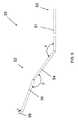
図9は、近位端50、遠位端52、並びに近位から遠位の順に、第1のセグメント54、第2のセグメント56、及び第3のセグメント58を有するワイヤ33の実施形態を示す。第1のセグメント54は主軸部51と第2のセグメント56との間に延在し得るもので、主軸部51と第1のセグメント54との間に画定される180度未満の第1の夾角αに付勢され得る。第2のセグメント56は第1のセグメント54と第3のセグメント58との間に延在し得るもので、第1のセグメント54と第2のセグメント56との間に画定される180度未満の第2の夾角βに付勢され得る。第3のセグメント58は第2のセグメント56から自由端まで延在し得るもので、第2のセグメント56と第3のセグメント58との間に画定される180度未満の第3の夾角γに付勢され得る。 FIG. 9 illustrates an embodiment of a
第2の夾角は第1の夾角より大きくてもよい。第1の夾角と第3の夾角との合計から第2の夾角を引いた差は、約70度〜約110度の範囲であり得る。第1の夾角と第3の夾角との合計から第2の夾角を引いた差は、約80度〜約100度の範囲であり得る。第1の夾角と第3の夾角との合計から第2の夾角を引いた差は、約90度であり得る。 The second depression angle may be larger than the first depression angle. The difference obtained by subtracting the second depression angle from the sum of the first depression angle and the third depression angle may range from about 70 degrees to about 110 degrees. The difference obtained by subtracting the second depression angle from the sum of the first depression angle and the third depression angle may range from about 80 degrees to about 100 degrees. The difference obtained by subtracting the second depression angle from the sum of the first depression angle and the third depression angle may be about 90 degrees.
ワイヤ33の第3のセグメント58の長さは、シース32の内径より小さくてもよい。例えば、第3のセグメント58の長さは0.028インチ未満であってもよく、又はシース32の内径の3分の2以下の長さであってもよい。 The length of the
主軸部51の重心軸から自由端までの垂直方向の距離は0.3インチ未満であってもよい。第1のセグメント54及び第2のセグメント56の各々の長さは、約0.2インチ〜約0.3インチの範囲、又は約0.24インチ〜約0.26インチの範囲であってもよい。第1のセグメント54の長さは約0.248インチ〜約0.25インチの範囲であってもよく、第2のセグメントの長さは約0.25インチ〜約0.252インチの範囲であってもよい。一実施形態において、第1のセグメント54の長さは0.249インチであってもよく、及び第2のセグメントの長さは0.2504インチであってもよい。 The vertical distance from the center of gravity of the
ワイヤ33の遠位端52は、互いに零角ではない角度で向き合う少なくとも2つの直線状のセグメントを備え得る。少なくとも2つの直線状のセグメントを有することにより、ワイヤの遠位先端をシースの壁に接触させることなくシースの中に差し込むことができ、さらに、ワイヤの先端(例えば、第3のセグメント)で血管壁を押し掻きながらワイヤの主軸部を血管壁に沿って送り込むことも可能であり得る。 The
遠位端52に位置するワイヤの先端は、使用目的に応じて様々な形状を有し得る。ワイヤの形は「非侵襲性」であってもよく、これはワイヤが、挿入によって血管に攣縮又は損傷を引き起こすことがほとんど又は全くないような形であり得ることを意味する。例えば、図10は、終端が半球形の自由端となっている遠位端52を示す。半球形の端部には、テクスチャを付与するか、又は機械的若しくは化学的に変質させることによって粗面化された表面を作り出し得る。他の非侵襲性の先端としては、全半径、又はJ型湾曲形状、若しくは単純に湾曲形状を有する端部を挙げることができる。 The tip of the wire located at the
図10は、半球形からワイヤ33に沿ってワイヤの近位端に向かって延在するスリーブを有する非侵襲性の先端を示す。スリーブ70は遠位先端に強度を加えることができ、従って擦過力が増加して接触表面積が増加するため、半球形の先端72が離れなくなる。 FIG. 10 shows a non-invasive tip having a sleeve extending from the hemisphere along the
他の実施形態において、遠位先端52は「攻撃的」で、遠位先端52が血管壁を擦過するように屈曲又は湾曲していてもよい。図9は、周縁が鋭い平坦な自由端を有する遠位端52を示す。攻撃的な遠位先端52はまた、縁部に斜角を付けて尖端を作ることによっても作り出され得る。サメのヒレのような切除ブレードを有する遠位先端もまた、攻撃的であり得る。遠位先端52を粗面化することで、遠位先端の切除部をより攻撃的にし、及び/又は血管壁に攣縮を生じさせるようにし得る。 In other embodiments, the
粗面化表面は、最初は滑らかなスチールを、研磨、機械加工、吹き付け、化学エッチング、例えば酸腐食(例えば、硝酸、フッ化水素酸、塩酸、及び/又は硫酸)に供することによって形成され得る。粗面化された外表面はまた、スリーブ70を形成するシートなどのシート状金属を不規則な形状のガイド上に圧延して不規則な表面を作ることによっても作り出され得る。 A roughened surface may be formed by first subjecting smooth steel to polishing, machining, spraying, chemical etching, such as acid corrosion (eg, nitric acid, hydrofluoric acid, hydrochloric acid, and / or sulfuric acid). . A roughened outer surface can also be created by rolling a sheet metal, such as the
また、第1、第2、及び/又は第3のセグメントの外表面は研磨剤で塗膜することによって表面が粗面化されてもよい。他の表面処理としては、中荒目やすり又はダイヤモンドグリットを挙げることができる。例えば、30グリットダイヤモンドでは攻撃的な表面が生じ、200グリットダイヤモンドでは非攻撃的な表面が生じ得る。 Further, the outer surface of the first, second, and / or third segment may be roughened by coating with an abrasive. Other surface treatments may include medium rough file or diamond grit. For example, a 30 grit diamond can produce an aggressive surface and a 200 grit diamond can produce a non-aggressive surface.
使用中、特に先端が粗面化されているとき、ワイヤを一定期間ごとにシースに再び封入することで、ワイヤの先端からのデブリの除去、及び器具の正常な動作の維持が促進され得る。 During use, particularly when the tip is roughened, re-encapsulating the wire in the sheath at regular intervals may facilitate the removal of debris from the tip of the wire and maintaining normal operation of the instrument.
攻撃的な表面はまた、ワイヤ33の第1のセグメント54及び/又は第2のセグメント56に対し、四角形、又は菱形、又は台形、又は平行四辺形、又は楕円形、又は三角形、又は五角形などの様々な形状のスクリューフライトに従うワイヤ33の長さに沿った第2のワイヤによるねじ状外形を導入することにより形成してもよい。 The aggressive surface can also be a square, rhombus, trapezoid, parallelogram, ellipse, triangle, pentagon, etc., for the
図10は、スリーブ70が先述した様々な方法の1つを用いて粗面化された外表面を有する第1のセグメント56を有する実施形態を示す。粗面化された表面処理を示すことに加え、図10はさらに、遠位先端に加重物が付けられたワイヤを例示し、この場合、加重は粗面化された外表面のスリーブにより加えられる。加重物はワイヤの重心に位置決めされるか、又は偏心して位置決めされ得る。偏心した加重物は、ワイヤを回転中に激しく揺動させ得る。激しい揺動は、加重物が重心に付けられたワイヤと比較して、血管に対しより攻撃的に動揺を与え得る。 FIG. 10 shows an embodiment in which the
ワイヤ33の遠位端52はまた、湾曲したセグメントも備え得る。湾曲したセグメントの曲率は一定であってもよく、又は他の曲線、例えば楕円形又は長円形の一部分などに従ってもよい。ワイヤ33の遠位端52はまた、湾曲したセグメントの遠位に直線状のセグメントも有し得る。一定の曲率の実施形態と同様に、直線状のセグメントを伴う湾曲部分の曲率は一定であってもよく、又は先述の形に従ってもよい。 The
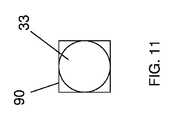
スプリング90がワイヤ33の遠位端52から第1のセグメント54及び/又は第2のセグメント56に沿って取り付けられ、それにより攻撃的な切除面が作り出されてもよい。スプリングの端部は複数の箇所がろう付けされ得る。スプリング90は、先述された様々な外形に従い得る。図11〜13は、それぞれ、四角形、台形、及び五角形のスクリューフライトに従うスプリングの断面図を示す。 A
様々な外形(例えば、四角形、三角形、平行四辺形、五角形)の尖った角部が血管壁を押し掻き、血管壁を切除し得る。ワイヤ33は、使用目的に応じて半球形か、又は平坦な自由端を有し得る。半球形の端部又は平坦な自由端はまた、テクスチャが付与されるか、又は粗面化されてもよい。 The sharp corners of various external shapes (eg, squares, triangles, parallelograms, pentagons) can scratch the vessel wall and excise the vessel wall. The
Claims (52)
Translated fromJapaneseハンドルであって、
モータと、
前記ハンドルに装着され、前記モータを電源と電気的に連結しない第1の状態と、前記モータを前記電源と連結する第2の状態との間を切り換え可能なトリガと、
前記モータにより回転駆動される雄型連結具と、
を有するハンドルと、
前記ハンドルと係合可能なカートリッジであって、
前記雄型連結具により係合可能なサイズ及び形状であり、且つ係合されると、前記雄型連結具によって回転する雌型連結具と、
前記雌型連結具に固定された近位端と、前記近位端から延在してその終端が遠位端である主軸部とを有するワイヤと、
前記カートリッジに固定され、そこから延在するシースであって、前記ワイヤが通るルーメンを画成するシースと、
を有するカートリッジと、
を備え、前記雌型連結具が前記雄型連結具により係合されていないとき、前記シースが前記ワイヤの前記遠位端を被覆し、及び前記雌型連結具が前記雄型連結具により係合されているとき、前記シースが前記ワイヤの前記遠位端を被覆しない、
血管治療用器具。A vascular treatment device,
A handle,
A motor,
A trigger mounted on the handle and switchable between a first state in which the motor is not electrically connected to a power source and a second state in which the motor is connected to the power source;
A male connector rotated by the motor;
A handle having
A cartridge engagable with the handle,
A female connector that is sized and shaped to be engageable by the male connector and that is rotated by the male connector when engaged;
A wire having a proximal end fixed to the female connector and a main shaft extending from the proximal end and terminating in a distal end;
A sheath secured to and extending from the cartridge, the sheath defining a lumen through which the wire passes;
A cartridge having
When the female connector is not engaged by the male connector, the sheath covers the distal end of the wire, and the female connector is engaged by the male connector. When mated, the sheath does not cover the distal end of the wire;
Vascular treatment device.
前記第1のセグメントが前記主軸部と前記第2のセグメントとの間に延在し、付勢されると第1の夾角で静止して、前記第1の夾角が、
前記主軸部と前記第1のセグメントとの間に画定され、且つ
180度未満であり、
前記第2のセグメントが前記第1のセグメントと前記第3のセグメントとの間に延在し、付勢されると第2の夾角で静止して、前記第2の夾角が、
前記第1のセグメントと前記第2のセグメントとの間に画定され、且つ
180度未満であり、及び
前記第3のセグメントが前記第2のセグメントから自由端まで延在し、付勢されると第3の夾角で静止して、前記第3の夾角が、
前記第2のセグメントと第3のセグメントとの間に画定され、且つ
180度未満である、
請求項1に記載の装置。The distal end comprises, in order from proximal to distal, a first segment, a second segment, and a third segment;
When the first segment extends between the main shaft portion and the second segment and is energized, the first segment stops at a first depression angle, and the first depression angle is
Defined between the main shaft portion and the first segment and less than 180 degrees;
The second segment extends between the first segment and the third segment, and when energized, stops at a second depression angle, and the second depression angle is
Defined between the first segment and the second segment and less than 180 degrees, and when the third segment extends from the second segment to a free end and is biased Still at the third depression angle, the third depression angle is
Defined between the second and third segments and less than 180 degrees;
The apparatus of claim 1.
2つの部品から形成されるケーシングを備え、
前記モータ及び前記雄型連結具を内蔵し、及び、
中に前記雄型連結具が位置決めされ、前記カートリッジと前記ハンドルとが係合されるときに前記カートリッジの前記雌型連結具を収容する収容部を画成する、
請求項1に記載の装置。The handle is
Comprising a casing formed from two parts,
Incorporating the motor and the male connector; and
Defining a receptacle for accommodating the female coupler of the cartridge when the male coupler is positioned therein and the cartridge and handle are engaged;
The apparatus of claim 1.
モータと、
前記ハンドルに装着され、前記モータを電源と電気的に連結しない第1の状態と、前記モータを前記電源と連結する第2の状態との間を切り換え可能なトリガと、
前記モータにより回転駆動される雄型連結具と、
を備え、前記ハンドルの1つ又は複数の部分が、中に前記トリガが少なくとも部分的に配置されるトリガリングを画成し、前記ハンドルが、前記ハンドルの前記トリガリングを画成する1つ又は複数の部分のみから支持されるとき平衡が保たれるように構成される、ハンドル。A handle,
A motor,
A trigger mounted on the handle and switchable between a first state in which the motor is not electrically connected to a power source and a second state in which the motor is connected to the power source;
A male connector rotated by the motor;
One or more portions of the handle define a trigger ring in which the trigger is at least partially disposed, and the handle defines one or more of the trigger ring of the handle A handle configured to be balanced when supported from multiple parts only.
近位端と、
遠位端と、
前記近位端と前記遠位端との間に延在する主軸部と、
を備え、
前記遠位端が、近位から遠位の順に、第1のセグメント、第2のセグメント、及び第3のセグメントを備え、
前記第1のセグメントが前記主軸部と前記第2のセグメントとの間に延在し、付勢されると第1の夾角となり、前記第1の夾角が、
前記主軸部と前記第1のセグメントとの間に画定され、且つ
180度未満であり、
前記第2のセグメントが前記第1のセグメントと前記第3のセグメントとの間に延在し、付勢されると第2の夾角となり、前記第2の夾角が、
前記第1のセグメントと前記第2のセグメントとの間に画定され、且つ
180度未満であり、
前記第3のセグメントが前記第2のセグメントから自由端まで延在し、付勢されると第3の夾角となり、前記第3の夾角が、
前記第2のセグメントと前記第3のセグメントとの間に画定され、且つ
180度未満である、
ワイヤ。A wire for use in a vascular treatment instrument,
A proximal end;
The distal end;
A main shaft portion extending between the proximal end and the distal end;
With
The distal end comprises, in order from proximal to distal, a first segment, a second segment, and a third segment;
When the first segment extends between the main shaft portion and the second segment and is biased, a first depression angle is obtained, and the first depression angle is
Defined between the main shaft portion and the first segment and less than 180 degrees;
When the second segment extends between the first segment and the third segment and is biased, the second depression angle is obtained, and the second depression angle is
Defined between the first segment and the second segment and less than 180 degrees;
When the third segment extends from the second segment to the free end and is biased, it becomes a third depression angle, and the third depression angle is
Defined between the second segment and the third segment and less than 180 degrees;
Wire.
ハンドルであって、
モータと、
前記モータにより回転駆動されるモータ連結具と、
前記ハンドルに装着され、前記モータを電源と電気的に連結しない第1の状態と、前記モータを前記電源と連結する第2の状態との間を切り換え可能なトリガと、
前記モータ連結具に固定される近位端と、そこから延在し、且つ終端が遠位端である主軸部とを有するワイヤと、
を有するハンドルと、
前記ハンドル内で第1の位置と第2の位置との間を移動可能なカートリッジと、
前記カートリッジに固定され、そこから延在するシースであって、前記ワイヤが通るルーメンを画成するシースと、
を備え、前記第1の位置において前記ワイヤの前記遠位端は露出されず、及び前記第2の位置において前記ワイヤの前記遠位端は露出される、血管治療用器具。A vascular treatment device,
A handle,
A motor,
A motor coupler that is rotationally driven by the motor;
A trigger mounted on the handle and switchable between a first state in which the motor is not electrically connected to a power source and a second state in which the motor is connected to the power source;
A wire having a proximal end secured to the motor coupler and a main shaft extending therefrom and terminating in a distal end;
A handle having
A cartridge movable between a first position and a second position within the handle;
A sheath secured to and extending from the cartridge, the sheath defining a lumen through which the wire passes;
A vascular treatment device wherein the distal end of the wire is not exposed in the first position and the distal end of the wire is exposed in the second position.
Applications Claiming Priority (5)
| Application Number | Priority Date | Filing Date | Title |
|---|---|---|---|
| US82552906P | 2006-09-13 | 2006-09-13 | |
| US60/825,529 | 2006-09-13 | ||
| US91611007P | 2007-05-04 | 2007-05-04 | |
| US60/916,110 | 2007-05-04 | ||
| PCT/US2007/078367WO2008033983A1 (en) | 2006-09-13 | 2007-09-13 | Vascular treatment device |
Publications (2)
| Publication Number | Publication Date |
|---|---|
| JP2010503479Atrue JP2010503479A (en) | 2010-02-04 |
| JP5286612B2 JP5286612B2 (en) | 2013-09-11 |
Family
ID=39184134
Family Applications (1)
| Application Number | Title | Priority Date | Filing Date |
|---|---|---|---|
| JP2009528466AActiveJP5286612B2 (en) | 2006-09-13 | 2007-09-13 | Vascular treatment instrument |
Country Status (9)
| Country | Link |
|---|---|
| US (4) | US7967834B2 (en) |
| EP (1) | EP2061385B1 (en) |
| JP (1) | JP5286612B2 (en) |
| CN (2) | CN101547653B (en) |
| AU (1) | AU2007296425B2 (en) |
| CA (3) | CA2871742C (en) |
| ES (1) | ES2498798T3 (en) |
| PL (1) | PL2061385T3 (en) |
| WO (1) | WO2008033983A1 (en) |
Cited By (7)
| Publication number | Priority date | Publication date | Assignee | Title |
|---|---|---|---|---|
| JP2014500761A (en)* | 2010-11-15 | 2014-01-16 | ヴァスキュラー インサイツ エルエルシー | Direction reversal vascular treatment device |
| JP2014500738A (en)* | 2010-10-19 | 2014-01-16 | ディスタル・アクセス・エルエルシー | Apparatus for rotating a medical device, system including the apparatus, and related methods |
| US8845621B2 (en) | 2010-10-19 | 2014-09-30 | Distal Access, Llc | Apparatus for rotating medical devices, systems including the apparatus, and associated methods |
| KR20140133811A (en)* | 2011-12-13 | 2014-11-20 | 배스큘러 인사이트, 엘엘씨 | Adhesive-based varicose vein treatment |
| JP2015535483A (en)* | 2012-11-30 | 2015-12-14 | ジャイラス・エーシーエムアイ・インコーポレーテッド | Micro debrider with replaceable replaceable parts and method of attaching parts |
| US11000307B2 (en) | 2010-10-19 | 2021-05-11 | Minerva Surgical Inc. | Apparatus for rotating medical devices, systems including the apparatus, and associated methods |
| US11446050B2 (en) | 2014-04-28 | 2022-09-20 | Minerva Surgical, Inc. | Tissue resectors with cutting wires, hand operated tissue resecting systems and associated methods |
Families Citing this family (48)
| Publication number | Priority date | Publication date | Assignee | Title |
|---|---|---|---|---|
| CN101547653B (en) | 2006-09-13 | 2012-02-29 | 瓦斯库勒英赛特有限公司 | Vascular Therapy Devices |
| US8448644B2 (en)* | 2006-11-02 | 2013-05-28 | Cooltouch Incorporated | Sonic endovenous catheter |
| US9084410B2 (en)* | 2010-08-11 | 2015-07-21 | Ralph Whitman | Grooming device |
| US9226792B2 (en) | 2012-06-12 | 2016-01-05 | Medtronic Advanced Energy Llc | Debridement device and method |
| US8956355B2 (en) | 2012-11-30 | 2015-02-17 | Gyrus Acmi, Inc. | Integrated blade assembly and identification circuit |
| US9358036B2 (en) | 2013-03-12 | 2016-06-07 | Gyrus Acmi, Inc. | Blade positioning device |
| US20150250523A1 (en)* | 2014-03-10 | 2015-09-10 | Terumo Kabushiki Kaisha | Method for treating varicose veins and intraluminal device used in such method |
| US20150250536A1 (en)* | 2014-03-10 | 2015-09-10 | Terumo Kabushiki Kaisha | Method for treating varicose veins and intraluminal device used in such method |
| US20150250522A1 (en)* | 2014-03-10 | 2015-09-10 | Terumo Kabushiki Kaisha | Method for treating varicose veins and intraluminal device used in such method |
| US9457153B2 (en) | 2014-08-29 | 2016-10-04 | Vascular Insights Llc | Syringe accessory |
| US9387050B2 (en) | 2014-09-15 | 2016-07-12 | Gyrus Acmi Inc. | Surgical system having detachable component and state detection circuit for detection of state of attachment of detachable component |
| WO2016060882A1 (en)* | 2014-10-14 | 2016-04-21 | Cardiovascular Systems, Inc. | Rotational atherectomy device with exchangeable drive shaft and meshing gears |
| AU2015360273B2 (en) | 2014-12-12 | 2020-05-07 | Wake Forest University Health Sciences | Incremental syringe |
| ES2975734T3 (en) | 2015-01-29 | 2024-07-12 | Becton Dickinson Co | Integrated Quick Insert Catheter |
| AU2016219980B2 (en) | 2015-02-18 | 2020-09-03 | Medtronic Xomed, Inc. | RF energy enabled tissue debridement device |
| US10188456B2 (en) | 2015-02-18 | 2019-01-29 | Medtronic Xomed, Inc. | Electrode assembly for RF energy enabled tissue debridement device |
| US10376302B2 (en) | 2015-02-18 | 2019-08-13 | Medtronic Xomed, Inc. | Rotating electrical connector for RF energy enabled tissue debridement device |
| US9820825B2 (en) | 2015-02-20 | 2017-11-21 | Gyrus Acmi Inc. | Surgical system having plurality of detachably attachable components and circuit for detecting target states of detachably attachable components and performing control based on detected target states, and method for providing surgical system |
| US10080875B2 (en)* | 2015-12-01 | 2018-09-25 | Medtronic Vascular, Inc. | Handle component for providing a pressurized material |
| USD802769S1 (en) | 2016-05-16 | 2017-11-14 | Teleflex Medical Incorporated | Thrombectomy handle assembly |
| GB201612925D0 (en)* | 2016-07-26 | 2016-09-07 | Provensis Ltd | Method and device for generating injectable foam |
| EP4018946A1 (en) | 2017-05-03 | 2022-06-29 | Medtronic Vascular, Inc. | Tissue-removing catheter |
| US11690645B2 (en) | 2017-05-03 | 2023-07-04 | Medtronic Vascular, Inc. | Tissue-removing catheter |
| CN111698958A (en)* | 2017-12-12 | 2020-09-22 | 波士顿科学国际有限公司 | Rotary medical device |
| CN118697424A (en) | 2018-11-16 | 2024-09-27 | 美敦力瓦斯科尔勒公司 | Tissue Removal Catheter |
| US11819236B2 (en) | 2019-05-17 | 2023-11-21 | Medtronic Vascular, Inc. | Tissue-removing catheter |
| US11890429B2 (en) | 2019-09-10 | 2024-02-06 | Bard Access Systems, Inc. | Rapidly inserted central catheter and methods thereof |
| BR112022005254A2 (en) | 2019-09-24 | 2022-06-14 | Bard Access Systems Inc | Acute central venous catheter and peripherally inserted venous catheter integrated |
| WO2021081434A1 (en) | 2019-10-25 | 2021-04-29 | Bard Access Systems, Inc. | Guidewire-management devices and methods thereof |
| CA3168492A1 (en) | 2020-01-23 | 2021-07-29 | Bard Access Systems, Inc. | Splitable catheter docking station system |
| CN113384798A (en) | 2020-03-13 | 2021-09-14 | 巴德阿克塞斯系统股份有限公司 | Guide wire management device and method thereof |
| KR20220153062A (en) | 2020-03-13 | 2022-11-17 | 바드 액세스 시스템즈, 인크. | GUIDEWIRE-MANAGEMENT DEVICES AND METHODS THEREOF |
| EP4135819A1 (en) | 2020-04-23 | 2023-02-22 | Bard Access Systems, Inc. | Rapidly insertable central catheters including catheter assemblies |
| KR102438221B1 (en) | 2020-05-13 | 2022-09-01 | 유펙스메드 주식회사 | A device for treating intravenous disease that injects chemical solutions with electronic control |
| WO2021236950A1 (en) | 2020-05-21 | 2021-11-25 | Bard Access Systems, Inc. | Rapidly insertable central catheters including catheter assemblies |
| CN111514445B (en)* | 2020-05-25 | 2025-04-04 | 苏州天鸿盛捷医疗器械有限公司 | A vascular treatment device |
| AU2021303150B2 (en) | 2020-06-29 | 2025-10-02 | Bard Access Systems, Inc. | Rapidly insertable central catheters including catheter assemblies and methods thereof |
| CA3186461A1 (en) | 2020-06-29 | 2022-01-06 | Bard Access Systems, Inc. | Rapidly insertable central catheters including assemblies |
| CN111938719B (en)* | 2020-08-18 | 2024-06-11 | 内蒙古工业大学 | Vascular therapeutic apparatus |
| AU2021371314B2 (en) | 2020-10-28 | 2025-09-25 | Bard Access Systems, Inc. | Catheter placement system with stiffening system |
| AU2021400331B2 (en) | 2020-12-17 | 2025-09-25 | Bard Access Systems, Inc. | Rapidly insertable central catheters and assemblies |
| EP4259256A1 (en) | 2020-12-21 | 2023-10-18 | Bard Access Systems, Inc. | Fluid path optimization in catheter insertion systems |
| EP4259254A1 (en) | 2020-12-21 | 2023-10-18 | Bard Access Systems, Inc. | Optimized structural support in catheter insertion systems |
| US11696793B2 (en) | 2021-03-19 | 2023-07-11 | Crossfire Medical Inc | Vascular ablation |
| US11980409B2 (en) | 2022-08-08 | 2024-05-14 | Crossfire Medical Inc | Segmental vascular ablation |
| US20240149020A1 (en) | 2022-11-04 | 2024-05-09 | Controlled Delivery Systems, Inc. | Catheters for the aspiration controlled delivery of closure agents |
| EP4611658A1 (en) | 2022-11-04 | 2025-09-10 | Solvein Inc. | Catheters and related methods for aspiration and controlled delivery of closure agents |
| CN116269602B (en)* | 2023-05-23 | 2023-09-01 | 苏州天鸿盛捷医疗器械有限公司 | Varicose vein intracavity closing device |
Citations (6)
| Publication number | Priority date | Publication date | Assignee | Title |
|---|---|---|---|---|
| JPH0542162A (en)* | 1991-08-15 | 1993-02-23 | Nissho Corp | Embolus excision catheter |
| JPH08503154A (en)* | 1992-11-13 | 1996-04-09 | シメッド ライフ システムズ インコーポレイテッド | Device and method for endovascular occlusion removal |
| US6129734A (en)* | 1997-01-21 | 2000-10-10 | Shturman Cardiology Systems, Inc. | Rotational atherectomy device with radially expandable prime mover coupling |
| JP2002506670A (en)* | 1998-03-16 | 2002-03-05 | シュターマン カーディオロジー システムズ,インコーポレイティド | Rotary atherectomy device with improved replaceable drive shaft cartridge |
| JP2004508096A (en)* | 2000-09-07 | 2004-03-18 | エンディコア メディカル インコーポレイテッド | Cerebral thrombectomy catheter |
| WO2006055265A1 (en)* | 2004-11-17 | 2006-05-26 | Rex Medical, L.P. | Rotational thrombectomy wire |
Family Cites Families (133)
| Publication number | Priority date | Publication date | Assignee | Title |
|---|---|---|---|---|
| US2212477A (en) | 1939-06-19 | 1940-08-20 | Herman J Mayer | Injection needle |
| US3405712A (en) | 1966-02-07 | 1968-10-15 | Richard L. Pierick | Desiccative syringe |
| US3530492A (en) | 1967-12-05 | 1970-09-22 | Jack R Ferber | Method and apparatus for administering hypodermic injections |
| US3633566A (en) | 1969-05-15 | 1972-01-11 | Systematics | Blood collecting method and device |
| US4278085A (en) | 1979-12-13 | 1981-07-14 | Baxter Travenol Laboratories, Inc. | Method and apparatus for metered infusion of fluids |
| US4403611A (en) | 1980-07-17 | 1983-09-13 | Babbitt Gerald J | Sinus evacuator apparatus |
| US4586921A (en) | 1983-08-17 | 1986-05-06 | Daniel Berson | Method of applying a local anesthetic agent to a wound |
| US4577514A (en) | 1984-04-09 | 1986-03-25 | Vanderbilt University | Method and apparatus for sampling liquid phase components from a liquid-semisolid fluid |
| US5217478A (en)* | 1987-02-18 | 1993-06-08 | Linvatec Corporation | Arthroscopic surgical instrument drive system |
| US4936845A (en) | 1987-03-17 | 1990-06-26 | Cordis Corporation | Catheter system having distal tip for opening obstructions |
| US4876109A (en) | 1987-04-13 | 1989-10-24 | Cardiac Pacemakers, Inc. | Soluble covering for cardiac pacing electrode |
| US4867156A (en)* | 1987-06-25 | 1989-09-19 | Stack Richard S | Percutaneous axial atheroectomy catheter assembly and method of using the same |
| US4857046A (en)* | 1987-10-21 | 1989-08-15 | Cordis Corporation | Drive catheter having helical pump drive shaft |
| US4854325A (en) | 1987-11-09 | 1989-08-08 | Stevens Robert C | Reciprocating guidewire method |
| US5047016A (en)* | 1987-12-21 | 1991-09-10 | Stuart M. Dolgin | Fluid passing apparatus with means for covering the same |
| US4906236A (en)* | 1988-08-29 | 1990-03-06 | Alberts David S | Self-sheathing hypodermic needle |
| DE3830909A1 (en) | 1988-09-10 | 1990-03-22 | Astra Meditec Ab | Varicose tube |
| US5019083A (en) | 1989-01-31 | 1991-05-28 | Advanced Osseous Technologies, Inc. | Implanting and removal of orthopedic prostheses |
| US5087244A (en)* | 1989-01-31 | 1992-02-11 | C. R. Bard, Inc. | Catheter and method for locally applying medication to the wall of a blood vessel or other body lumen |
| US5087265A (en)* | 1989-02-17 | 1992-02-11 | American Biomed, Inc. | Distal atherectomy catheter |
| US5022399A (en) | 1989-05-10 | 1991-06-11 | Biegeleisen Ken P | Venoscope |
| WO1991000752A1 (en)* | 1989-06-28 | 1991-01-24 | Zimmon David S | Balloon tamponade devices and methods for their placement |
| WO1991002494A1 (en)* | 1989-08-18 | 1991-03-07 | Evi Corporation | Catheter atherotome |
| FR2651682B1 (en) | 1989-09-13 | 1991-10-25 | Cadet Pierre | APPARATUS FOR THE DESTRUCTION OF VARICAS OF LOWER MEMBERS IN MAN. |
| US5100425A (en) | 1989-09-14 | 1992-03-31 | Medintec R&D Limited Partnership | Expandable transluminal atherectomy catheter system and method for the treatment of arterial stenoses |
| US5116352A (en)* | 1989-10-06 | 1992-05-26 | Angiomed Ag | Apparatus for removing deposits from vessels |
| US5026384A (en)* | 1989-11-07 | 1991-06-25 | Interventional Technologies, Inc. | Atherectomy systems and methods |
| AU8074591A (en)* | 1990-06-15 | 1992-01-07 | Cortrak Medical, Inc. | Drug delivery apparatus and method |
| US5135517A (en) | 1990-07-19 | 1992-08-04 | Catheter Research, Inc. | Expandable tube-positioning apparatus |
| US5304115A (en)* | 1991-01-11 | 1994-04-19 | Baxter International Inc. | Ultrasonic angioplasty device incorporating improved transmission member and ablation probe |
| US5176646A (en) | 1991-02-19 | 1993-01-05 | Takayuki Kuroda | Motorized syringe pump |
| EP0501081B1 (en) | 1991-02-28 | 1996-05-15 | Pierre Cadet | Apparatus for the destruction of varicose veins |
| US5358507A (en)* | 1991-07-26 | 1994-10-25 | Pat O. Daily | Thromboendarterectomy suction dissector |
| US5350390A (en)* | 1992-03-25 | 1994-09-27 | Arieh Sher | Device for removal of intraluminal occlusions |
| WO1993019679A1 (en)* | 1992-04-07 | 1993-10-14 | The Johns Hopkins University | A percutaneous mechanical fragmentation catheter system |
| US5361768A (en) | 1992-06-30 | 1994-11-08 | Cardiovascular Imaging Systems, Inc. | Automated longitudinal position translator for ultrasonic imaging probes, and methods of using same |
| US5356418A (en)* | 1992-10-28 | 1994-10-18 | Shturman Cardiology Systems, Inc. | Apparatus and method for rotational atherectomy |
| US5643297A (en)* | 1992-11-09 | 1997-07-01 | Endovascular Instruments, Inc. | Intra-artery obstruction clearing apparatus and methods |
| US5514151A (en)* | 1992-12-02 | 1996-05-07 | Fogarty; Thomas J. | Valvulotome with a laterally offset curved cutting edge |
| CN2148536Y (en)* | 1993-02-19 | 1993-12-08 | 董国祥 | Tube for extracting embolus from venous |
| US5776153A (en) | 1993-07-03 | 1998-07-07 | Medical Miracles Company Limited | Angioplasty catheter with guidewire |
| US5449351A (en) | 1993-09-09 | 1995-09-12 | Zohmann; Walter A. | Atraumatic needle for lumbar puncture |
| US6673025B1 (en)* | 1993-12-01 | 2004-01-06 | Advanced Cardiovascular Systems, Inc. | Polymer coated guidewire |
| US5490852A (en)* | 1994-02-16 | 1996-02-13 | Azer; Samir N. | Orthopedic awl |
| US5415636A (en)* | 1994-04-13 | 1995-05-16 | Schneider (Usa) Inc | Dilation-drug delivery catheter |
| US5836905A (en)* | 1994-06-20 | 1998-11-17 | Lemelson; Jerome H. | Apparatus and methods for gene therapy |
| US5891108A (en)* | 1994-09-12 | 1999-04-06 | Cordis Corporation | Drug delivery stent |
| US5611357A (en)* | 1995-02-09 | 1997-03-18 | Suval; William D. | Method and apparatus for treating varicose veins |
| US5624452A (en)* | 1995-04-07 | 1997-04-29 | Ethicon Endo-Surgery, Inc. | Hemostatic surgical cutting or stapling instrument |
| US5707355A (en) | 1995-11-15 | 1998-01-13 | Zimmon Science Corporation | Apparatus and method for the treatment of esophageal varices and mucosal neoplasms |
| US5675228A (en)* | 1995-12-18 | 1997-10-07 | General Electric Company | Methods and apparatus for controlling energization of a motor |
| ATE481124T1 (en) | 1996-02-27 | 2010-10-15 | Braun Melsungen Ag | NEEDLE TIP PROTECTION FOR SUBCUTANEOUS INJECTIONS |
| CN1226180A (en) | 1996-06-10 | 1999-08-18 | 伊兰股份有限公司 | Needle for subcutaneous delivery of fluids |
| IE80772B1 (en) | 1996-06-10 | 1999-02-10 | Elan Corp Plc | Delivery needle |
| US5976164A (en)* | 1996-09-13 | 1999-11-02 | Eclipse Surgical Technologies, Inc. | Method and apparatus for myocardial revascularization and/or biopsy of the heart |
| US6193735B1 (en) | 1996-09-16 | 2001-02-27 | Robert C. Stevens | Combined rotary and axial reciprocating guide wire |
| US5957941A (en) | 1996-09-27 | 1999-09-28 | Boston Scientific Corporation | Catheter system and drive assembly thereof |
| US6311692B1 (en)* | 1996-10-22 | 2001-11-06 | Epicor, Inc. | Apparatus and method for diagnosis and therapy of electrophysiological disease |
| US6290675B1 (en) | 1997-01-09 | 2001-09-18 | Endosonics Corporation | Device for withdrawing a catheter |
| US5893857A (en) | 1997-01-21 | 1999-04-13 | Shturman Cardiology Systems, Inc. | Handle for atherectomy device |
| US5911700A (en)* | 1997-03-11 | 1999-06-15 | Microaire Surgical Instruments | Power assisted liposuction and lipoinjection equipment |
| US5908395A (en) | 1997-03-17 | 1999-06-01 | Advanced Cardiovascular Systems, Inc. | Vibrating guidewire |
| US7037316B2 (en)* | 1997-07-24 | 2006-05-02 | Mcguckin Jr James F | Rotational thrombectomy device |
| WO2001028618A2 (en) | 1999-10-22 | 2001-04-26 | Boston Scientific Corporation | Double balloon thrombectomy catheter |
| ES2224418T3 (en) | 1997-07-24 | 2005-03-01 | Rex Medical, L.P. | ROTATING THROMBECTOMY APPARATUS WITH STATIONARY WAVE. |
| US6090118A (en)* | 1998-07-23 | 2000-07-18 | Mcguckin, Jr.; James F. | Rotational thrombectomy apparatus and method with standing wave |
| US5893858A (en) | 1997-10-06 | 1999-04-13 | Smith & Nephew, Inc. | Method for removing veins |
| US6824550B1 (en)* | 2000-04-06 | 2004-11-30 | Norbon Medical, Inc. | Guidewire for crossing occlusions or stenosis |
| US6159196A (en)* | 1998-03-09 | 2000-12-12 | Ruiz; Carlos | Methods and apparatus for transvascular muscular revascularization and drug delivery |
| US6001112A (en) | 1998-04-10 | 1999-12-14 | Endicor Medical, Inc. | Rotational atherectomy device |
| US6231518B1 (en)* | 1998-05-26 | 2001-05-15 | Comedicus Incorporated | Intrapericardial electrophysiological procedures |
| US6273882B1 (en)* | 1998-06-18 | 2001-08-14 | Scimed Life Systems | Snap handle assembly for an endoscopic instrument |
| US6369039B1 (en)* | 1998-06-30 | 2002-04-09 | Scimed Life Sytems, Inc. | High efficiency local drug delivery |
| US6319227B1 (en) | 1998-08-05 | 2001-11-20 | Scimed Life Systems, Inc. | Automatic/manual longitudinal position translator and rotary drive system for catheters |
| US6261304B1 (en)* | 1998-09-10 | 2001-07-17 | Percardia, Inc. | Delivery methods for left ventricular conduit |
| US6641558B1 (en) | 1998-09-30 | 2003-11-04 | A-Med Systems, Inc. | Method and apparatus for preventing air embolisms |
| US6048332A (en)* | 1998-10-09 | 2000-04-11 | Ave Connaught | Dimpled porous infusion balloon |
| US6238335B1 (en) | 1998-12-11 | 2001-05-29 | Enteric Medical Technologies, Inc. | Method for treating gastroesophageal reflux disease and apparatus for use therewith |
| US6482215B1 (en)* | 1999-02-02 | 2002-11-19 | Samuel Shiber | Adjustable vessel cleaner and method |
| DE60020566T2 (en) | 1999-07-30 | 2006-05-04 | Boston Scientific Ltd., St. Michael | CATHETER WITH DRIVE AND CLUTCH FOR TURNING AND LENGTH SHIFTING |
| US6709427B1 (en) | 1999-08-05 | 2004-03-23 | Kensey Nash Corporation | Systems and methods for delivering agents into targeted tissue of a living being |
| JP3390704B2 (en) | 1999-08-26 | 2003-03-31 | 株式会社半導体理工学研究センター | Ferroelectric nonvolatile memory |
| DE69926889T2 (en) | 1999-09-09 | 2006-06-14 | Schneider Europ Gmbh Buelach | Guide to medical devices |
| US6613026B1 (en) | 1999-12-08 | 2003-09-02 | Scimed Life Systems, Inc. | Lateral needle-less injection apparatus and method |
| US6663613B1 (en)* | 2000-01-25 | 2003-12-16 | Bacchus Vascular, Inc. | System and methods for clot dissolution |
| US6402745B1 (en) | 2000-02-23 | 2002-06-11 | Peter J. Wilk | Intravenous whip electrode for vein ablation |
| US7344546B2 (en) | 2000-04-05 | 2008-03-18 | Pathway Medical Technologies | Intralumenal material removal using a cutting device for differential cutting |
| WO2001076458A2 (en) | 2000-04-07 | 2001-10-18 | Bacchus Vascular, Inc. | Methods and device for percutaneous remote endarterectomy |
| US6517528B1 (en) | 2000-04-13 | 2003-02-11 | Scimed Life Systems, Inc. | Magnetic catheter drive shaft clutch |
| US6645221B1 (en) | 2000-05-30 | 2003-11-11 | Zuli, Holdings Ltd. | Active arterial embolization filter |
| USD450843S1 (en)* | 2000-05-30 | 2001-11-20 | Boston Scientific Corporation | Thrombectomy handpiece |
| US7077836B2 (en)* | 2000-07-21 | 2006-07-18 | Vein Rx, Inc. | Methods and apparatus for sclerosing the wall of a varicose vein |
| US20030120256A1 (en)* | 2001-07-03 | 2003-06-26 | Syntheon, Llc | Methods and apparatus for sclerosing the wall of a varicose vein |
| US6544221B1 (en)* | 2000-08-30 | 2003-04-08 | Advanced Cardiovascular Systems, Inc. | Balloon designs for drug delivery |
| US6679886B2 (en)* | 2000-09-01 | 2004-01-20 | Synthes (Usa) | Tools and methods for creating cavities in bone |
| DE10059742A1 (en) | 2000-12-01 | 2002-06-13 | Angiolas Medical Gmbh | System for treating vascular adhesions |
| US6623452B2 (en)* | 2000-12-19 | 2003-09-23 | Scimed Life Systems, Inc. | Drug delivery catheter having a highly compliant balloon with infusion holes |
| US6669652B2 (en)* | 2000-12-21 | 2003-12-30 | Advanced Cardiovascular Systems, Inc. | Guidewire with tapered distal coil |
| US6969373B2 (en) | 2001-04-13 | 2005-11-29 | Tricardia, Llc | Syringe system |
| US7041068B2 (en)* | 2001-06-12 | 2006-05-09 | Pelikan Technologies, Inc. | Sampling module device and method |
| US6599307B1 (en) | 2001-06-29 | 2003-07-29 | Advanced Cardiovascular Systems, Inc. | Filter device for embolic protection systems |
| US20030013986A1 (en)* | 2001-07-12 | 2003-01-16 | Vahid Saadat | Device for sensing temperature profile of a hollow body organ |
| US6726674B2 (en)* | 2001-09-04 | 2004-04-27 | Jomed Gmbh | Methods for minimally invasive, localized delivery of sclerotherapeutic agents |
| US6852118B2 (en)* | 2001-10-19 | 2005-02-08 | Shturman Cardiology Systems, Inc. | Self-indexing coupling for rotational angioplasty device |
| US20070219464A1 (en)* | 2002-03-22 | 2007-09-20 | Stephen Davis | Guidewire with deflectable re-entry tip |
| US9440046B2 (en) | 2002-04-04 | 2016-09-13 | Angiodynamics, Inc. | Venous insufficiency treatment method |
| JP2005525862A (en)* | 2002-05-17 | 2005-09-02 | オーナックス・メディカル・インコーポレーテッド | Surgical suture instrument and method of use thereof |
| EP2039298B1 (en) | 2002-05-31 | 2017-10-25 | Vidacare LLC | Apparatus to access bone marrow |
| US7811260B2 (en) | 2002-05-31 | 2010-10-12 | Vidacare Corporation | Apparatus and method to inject fluids into bone marrow and other target sites |
| US7458967B2 (en) | 2003-10-31 | 2008-12-02 | Angiodynamics, Inc. | Endovascular treatment apparatus and method |
| US20040147934A1 (en) | 2002-10-18 | 2004-07-29 | Kiester P. Douglas | Oscillating, steerable, surgical burring tool and method of using the same |
| EP1442720A1 (en) | 2003-01-31 | 2004-08-04 | Tre Esse Progettazione Biomedica S.r.l | Apparatus for the maneuvering of flexible catheters in the human cardiovascular system |
| US20040199151A1 (en) | 2003-04-03 | 2004-10-07 | Ceramoptec Industries, Inc. | Power regulated medical underskin irradiation treament system |
| US7862575B2 (en)* | 2003-05-21 | 2011-01-04 | Yale University | Vascular ablation apparatus and method |
| US20040236313A1 (en) | 2003-05-21 | 2004-11-25 | Klein Jeffrey A. | Infiltration cannula |
| WO2004110519A2 (en)* | 2003-06-12 | 2004-12-23 | Lake Region Manufacturing, Inc. | S-shape guidewire |
| EP1689335A1 (en) | 2003-09-05 | 2006-08-16 | Sightrate B.V. | Device for separation of corneal epithelium |
| GB0327957D0 (en) | 2003-12-03 | 2004-01-07 | Btg Int Ltd | Apparatus for delivering foam |
| US20060224110A1 (en) | 2005-03-17 | 2006-10-05 | Scott Michael J | Methods for minimally invasive vascular access |
| DE102005017546A1 (en) | 2005-04-16 | 2006-10-19 | Impella Cardiosystems Gmbh | Method for controlling a blood pump |
| US8083664B2 (en) | 2005-05-25 | 2011-12-27 | Maquet Cardiovascular Llc | Surgical stabilizers and methods for use in reduced-access surgical sites |
| EP1907041B1 (en) | 2005-07-11 | 2019-02-20 | Catheter Precision, Inc. | Remotely controlled catheter insertion system |
| EP1908406B1 (en) | 2005-07-25 | 2016-08-17 | Hakko Co., Ltd. | Ultrasonic puncture needle |
| AU2007269274A1 (en) | 2006-06-30 | 2008-01-10 | Atheromed, Inc. | Atherectomy devices and methods |
| CN101547653B (en) | 2006-09-13 | 2012-02-29 | 瓦斯库勒英赛特有限公司 | Vascular Therapy Devices |
| US8551020B2 (en)* | 2006-09-13 | 2013-10-08 | Boston Scientific Scimed, Inc. | Crossing guidewire |
| US20080172012A1 (en) | 2006-10-31 | 2008-07-17 | Hiniduma-Lokuge Prasanga D | Injection needle having lateral delivery ports and method for the manufacture thereof |
| US20080300571A1 (en) | 2007-05-30 | 2008-12-04 | Lepivert Patrick | Process and device for selectively treating interstitial tissue |
| US20090018486A1 (en) | 2007-07-13 | 2009-01-15 | Menachem Goren | Diagnosis and treatment of vericocele and prostate disorders |
| US8657821B2 (en) | 2008-11-14 | 2014-02-25 | Revascular Therapeutics Inc. | Method and system for reversibly controlled drilling of luminal occlusions |
| EP2395924B1 (en) | 2009-02-10 | 2021-03-24 | Vesatek, LLC | Apparatus for manipulating a surgical guidewire |
| CA2753207C (en) | 2009-02-20 | 2017-07-11 | Sapheon, Inc. | Methods and devices for venous occlusion for the treatment of venous insufficiency |
| GB0905748D0 (en) | 2009-04-03 | 2009-05-20 | Shturman Leonid | Rotational atherectomy device with eccentric abrasive element and method of use |
- 2007
- 2007-09-13CNCN200780033995XApatent/CN101547653B/enactiveActive
- 2007-09-13USUS12/438,314patent/US7967834B2/enactiveActive
- 2007-09-13WOPCT/US2007/078367patent/WO2008033983A1/enactiveApplication Filing
- 2007-09-13PLPL07842399Tpatent/PL2061385T3/enunknown
- 2007-09-13CNCN201010546216XApatent/CN101987033B/enactiveActive
- 2007-09-13ESES07842399.3Tpatent/ES2498798T3/enactiveActive
- 2007-09-13AUAU2007296425Apatent/AU2007296425B2/enactiveActive
- 2007-09-13CACA2871742Apatent/CA2871742C/enactiveActive
- 2007-09-13CACA2921604Apatent/CA2921604C/enactiveActive
- 2007-09-13EPEP07842399.3Apatent/EP2061385B1/enactiveActive
- 2007-09-13JPJP2009528466Apatent/JP5286612B2/enactiveActive
- 2007-09-13CACA2662958Apatent/CA2662958C/enactiveActive
- 2010
- 2010-11-19USUS12/950,488patent/US20110066142A1/ennot_activeAbandoned
- 2015
- 2015-11-20USUS14/947,256patent/US10463388B2/enactiveActive
- 2019
- 2019-11-04USUS16/673,501patent/US11903608B2/enactiveActive
Patent Citations (6)
| Publication number | Priority date | Publication date | Assignee | Title |
|---|---|---|---|---|
| JPH0542162A (en)* | 1991-08-15 | 1993-02-23 | Nissho Corp | Embolus excision catheter |
| JPH08503154A (en)* | 1992-11-13 | 1996-04-09 | シメッド ライフ システムズ インコーポレイテッド | Device and method for endovascular occlusion removal |
| US6129734A (en)* | 1997-01-21 | 2000-10-10 | Shturman Cardiology Systems, Inc. | Rotational atherectomy device with radially expandable prime mover coupling |
| JP2002506670A (en)* | 1998-03-16 | 2002-03-05 | シュターマン カーディオロジー システムズ,インコーポレイティド | Rotary atherectomy device with improved replaceable drive shaft cartridge |
| JP2004508096A (en)* | 2000-09-07 | 2004-03-18 | エンディコア メディカル インコーポレイテッド | Cerebral thrombectomy catheter |
| WO2006055265A1 (en)* | 2004-11-17 | 2006-05-26 | Rex Medical, L.P. | Rotational thrombectomy wire |
Cited By (21)
| Publication number | Priority date | Publication date | Assignee | Title |
|---|---|---|---|---|
| US9107691B2 (en) | 2010-10-19 | 2015-08-18 | Distal Access, Llc | Apparatus for rotating medical devices, systems including the apparatus, and associated methods |
| US12171456B2 (en) | 2010-10-19 | 2024-12-24 | Minerva Surgical, Inc. | Apparatus for rotating medical devices, systems including the apparatus, and associated methods |
| US11000307B2 (en) | 2010-10-19 | 2021-05-11 | Minerva Surgical Inc. | Apparatus for rotating medical devices, systems including the apparatus, and associated methods |
| JP2014500738A (en)* | 2010-10-19 | 2014-01-16 | ディスタル・アクセス・エルエルシー | Apparatus for rotating a medical device, system including the apparatus, and related methods |
| US8845621B2 (en) | 2010-10-19 | 2014-09-30 | Distal Access, Llc | Apparatus for rotating medical devices, systems including the apparatus, and associated methods |
| JP2019088798A (en)* | 2010-11-15 | 2019-06-13 | ヴァスキュラー インサイツ エルエルシー | Direction reversal blood vessel treatment device |
| JP2018008079A (en)* | 2010-11-15 | 2018-01-18 | ヴァスキュラー インサイツ エルエルシー | Direction reversing vascular treatment device |
| JP2014500762A (en)* | 2010-11-15 | 2014-01-16 | ヴァスキュラー インサイツ エルエルシー | Vascular treatment apparatus and method |
| US11241250B2 (en) | 2010-11-15 | 2022-02-08 | Merit Medical Systems, Inc. | Vascular treatment devices and methods |
| US9375216B2 (en) | 2010-11-15 | 2016-06-28 | Vascular Insights, Llc | Direction reversing vascular treatment device |
| JP2016120320A (en)* | 2010-11-15 | 2016-07-07 | ヴァスキュラー インサイツ エルエルシー | Direction reversing vascular treatment device |
| US9585667B2 (en) | 2010-11-15 | 2017-03-07 | Vascular Insights Llc | Sclerotherapy catheter with lumen having wire rotated by motor and simultaneous withdrawal from vein |
| JP2014500760A (en)* | 2010-11-15 | 2014-01-16 | ヴァスキュラー インサイツ エルエルシー | Vascular treatment device |
| JP2014500761A (en)* | 2010-11-15 | 2014-01-16 | ヴァスキュラー インサイツ エルエルシー | Direction reversal vascular treatment device |
| JP2018034006A (en)* | 2011-12-13 | 2018-03-08 | ヴァスキュラー インサイツ エルエルシーVascular Insights, LLC | Vascular treatment device |
| KR101995043B1 (en)* | 2011-12-13 | 2019-07-01 | 배스큘러 인사이트, 엘엘씨 | Adhesive-based varicose vein treatment |
| JP2015503951A (en)* | 2011-12-13 | 2015-02-05 | ヴァスキュラー インサイツ エルエルシーVascular Insights, LLC | Adhesive extended serpentine vein treatment |
| KR20140133811A (en)* | 2011-12-13 | 2014-11-20 | 배스큘러 인사이트, 엘엘씨 | Adhesive-based varicose vein treatment |
| JP2018110887A (en)* | 2012-11-30 | 2018-07-19 | ジャイラス・エーシーエムアイ・インコーポレーテッド | Micro debrider with replaceable replaceable parts and method of attaching parts |
| JP2015535483A (en)* | 2012-11-30 | 2015-12-14 | ジャイラス・エーシーエムアイ・インコーポレーテッド | Micro debrider with replaceable replaceable parts and method of attaching parts |
| US11446050B2 (en) | 2014-04-28 | 2022-09-20 | Minerva Surgical, Inc. | Tissue resectors with cutting wires, hand operated tissue resecting systems and associated methods |
Also Published As
| Publication number | Publication date |
|---|---|
| US20110066142A1 (en) | 2011-03-17 |
| PL2061385T3 (en) | 2015-06-30 |
| EP2061385A1 (en) | 2009-05-27 |
| CA2921604C (en) | 2020-02-25 |
| WO2008033983A1 (en) | 2008-03-20 |
| EP2061385A4 (en) | 2013-05-08 |
| CA2662958C (en) | 2015-01-13 |
| CA2871742A1 (en) | 2008-03-20 |
| US11903608B2 (en) | 2024-02-20 |
| CN101547653A (en) | 2009-09-30 |
| EP2061385B1 (en) | 2014-06-04 |
| US20160338728A1 (en) | 2016-11-24 |
| CA2921604A1 (en) | 2008-03-20 |
| US20090270889A1 (en) | 2009-10-29 |
| US20200138475A1 (en) | 2020-05-07 |
| AU2007296425A1 (en) | 2008-03-20 |
| CA2662958A1 (en) | 2008-03-20 |
| CA2871742C (en) | 2016-05-10 |
| CN101987033B (en) | 2012-10-03 |
| CN101547653B (en) | 2012-02-29 |
| US10463388B2 (en) | 2019-11-05 |
| ES2498798T3 (en) | 2014-09-25 |
| US7967834B2 (en) | 2011-06-28 |
| JP5286612B2 (en) | 2013-09-11 |
| AU2007296425B2 (en) | 2014-01-23 |
| CN101987033A (en) | 2011-03-23 |
Similar Documents
| Publication | Publication Date | Title |
|---|---|---|
| JP5286612B2 (en) | Vascular treatment instrument | |
| CA2858580C (en) | Adhesive-based varicose vein treatment | |
| US20200113575A1 (en) | Vascular treatment apparatus with auto injection device and related methods | |
| AU2018203595B2 (en) | Vascular treatment device | |
| AU2014202227B2 (en) | Vascular treatment device | |
| KR20250048315A (en) | segmental vascular resection |
Legal Events
| Date | Code | Title | Description |
|---|---|---|---|
| A621 | Written request for application examination | Free format text:JAPANESE INTERMEDIATE CODE: A621 Effective date:20100910 | |
| A521 | Request for written amendment filed | Free format text:JAPANESE INTERMEDIATE CODE: A523 Effective date:20111116 | |
| A521 | Request for written amendment filed | Free format text:JAPANESE INTERMEDIATE CODE: A523 Effective date:20120216 | |
| A131 | Notification of reasons for refusal | Free format text:JAPANESE INTERMEDIATE CODE: A131 Effective date:20120612 | |
| A601 | Written request for extension of time | Free format text:JAPANESE INTERMEDIATE CODE: A601 Effective date:20120912 | |
| A601 | Written request for extension of time | Free format text:JAPANESE INTERMEDIATE CODE: A601 Effective date:20121010 | |
| A521 | Request for written amendment filed | Free format text:JAPANESE INTERMEDIATE CODE: A523 Effective date:20121112 | |
| A521 | Request for written amendment filed | Free format text:JAPANESE INTERMEDIATE CODE: A523 Effective date:20121220 | |
| A602 | Written permission of extension of time | Free format text:JAPANESE INTERMEDIATE CODE: A602 Effective date:20121112 | |
| TRDD | Decision of grant or rejection written | ||
| A01 | Written decision to grant a patent or to grant a registration (utility model) | Free format text:JAPANESE INTERMEDIATE CODE: A01 Effective date:20130212 | |
| A61 | First payment of annual fees (during grant procedure) | Free format text:JAPANESE INTERMEDIATE CODE: A61 Effective date:20130312 | |
| A61 | First payment of annual fees (during grant procedure) | Free format text:JAPANESE INTERMEDIATE CODE: A61 Effective date:20130516 | |
| R150 | Certificate of patent or registration of utility model | Ref document number:5286612 Country of ref document:JP Free format text:JAPANESE INTERMEDIATE CODE: R150 | |
| R250 | Receipt of annual fees | Free format text:JAPANESE INTERMEDIATE CODE: R250 | |
| R250 | Receipt of annual fees | Free format text:JAPANESE INTERMEDIATE CODE: R250 | |
| R250 | Receipt of annual fees | Free format text:JAPANESE INTERMEDIATE CODE: R250 | |
| R250 | Receipt of annual fees | Free format text:JAPANESE INTERMEDIATE CODE: R250 | |
| R250 | Receipt of annual fees | Free format text:JAPANESE INTERMEDIATE CODE: R250 | |
| S111 | Request for change of ownership or part of ownership | Free format text:JAPANESE INTERMEDIATE CODE: R313113 | |
| R350 | Written notification of registration of transfer | Free format text:JAPANESE INTERMEDIATE CODE: R350 | |
| R250 | Receipt of annual fees | Free format text:JAPANESE INTERMEDIATE CODE: R250 | |
| R250 | Receipt of annual fees | Free format text:JAPANESE INTERMEDIATE CODE: R250 | |
| R250 | Receipt of annual fees | Free format text:JAPANESE INTERMEDIATE CODE: R250 | |
| R250 | Receipt of annual fees | Free format text:JAPANESE INTERMEDIATE CODE: R250 | |
| R250 | Receipt of annual fees | Free format text:JAPANESE INTERMEDIATE CODE: R250 |