JP2010502314A - Guide wire and guide insert placement assembly for over-the-wire catheter placement and methods of use - Google Patents
Guide wire and guide insert placement assembly for over-the-wire catheter placement and methods of useDownload PDFInfo
- Publication number
- JP2010502314A JP2010502314AJP2009526988AJP2009526988AJP2010502314AJP 2010502314 AJP2010502314 AJP 2010502314AJP 2009526988 AJP2009526988 AJP 2009526988AJP 2009526988 AJP2009526988 AJP 2009526988AJP 2010502314 AJP2010502314 AJP 2010502314A
- Authority
- JP
- Japan
- Prior art keywords
- guide insert
- assembly
- guide
- insert assembly
- radiating element
- Prior art date
- Legal status (The legal status is an assumption and is not a legal conclusion. Google has not performed a legal analysis and makes no representation as to the accuracy of the status listed.)
- Pending
Links
- 238000000034methodMethods0.000titleabstractdescription48
- 230000001939inductive effectEffects0.000claimsabstractdescription72
- 230000008878couplingEffects0.000claimsabstractdescription24
- 238000010168coupling processMethods0.000claimsabstractdescription24
- 238000005859coupling reactionMethods0.000claimsabstractdescription24
- 230000005670electromagnetic radiationEffects0.000claimsabstractdescription21
- 239000000463materialSubstances0.000claimsdescription11
- 230000005540biological transmissionEffects0.000claimsdescription6
- 238000002847impedance measurementMethods0.000claimsdescription5
- 230000005856abnormalityEffects0.000claims1
- 230000008569processEffects0.000abstractdescription6
- 210000001367arteryAnatomy0.000description7
- 238000001514detection methodMethods0.000description7
- 238000003384imaging methodMethods0.000description7
- 238000003780insertionMethods0.000description7
- 230000037431insertionEffects0.000description7
- 210000003462veinAnatomy0.000description6
- 210000004204blood vesselAnatomy0.000description5
- 238000011282treatmentMethods0.000description5
- 239000012530fluidSubstances0.000description4
- 230000004907fluxEffects0.000description4
- 210000000056organAnatomy0.000description4
- 210000005166vasculatureAnatomy0.000description4
- 238000004804windingMethods0.000description4
- 239000011888foilSubstances0.000description3
- 238000004519manufacturing processMethods0.000description3
- 238000012986modificationMethods0.000description3
- 230000004048modificationEffects0.000description3
- 238000012546transferMethods0.000description3
- 208000022211Arteriovenous MalformationsDiseases0.000description2
- 206010028980NeoplasmDiseases0.000description2
- 238000002399angioplastyMethods0.000description2
- 230000005744arteriovenous malformationEffects0.000description2
- 238000004364calculation methodMethods0.000description2
- 238000012790confirmationMethods0.000description2
- 238000013461designMethods0.000description2
- 238000010586diagramMethods0.000description2
- 239000003814drugSubstances0.000description2
- 229940079593drugDrugs0.000description2
- 238000005516engineering processMethods0.000description2
- 230000036512infertilityEffects0.000description2
- 238000013152interventional procedureMethods0.000description2
- 239000007788liquidSubstances0.000description2
- 238000005259measurementMethods0.000description2
- 230000005855radiationEffects0.000description2
- 239000000758substrateSubstances0.000description2
- 238000012360testing methodMethods0.000description2
- 230000001225therapeutic effectEffects0.000description2
- 230000002792vascularEffects0.000description2
- 210000002620vena cava superiorAnatomy0.000description2
- 208000031481Pathologic ConstrictionDiseases0.000description1
- 229910000831SteelInorganic materials0.000description1
- 230000002159abnormal effectEffects0.000description1
- 230000009118appropriate responseEffects0.000description1
- 238000012550auditMethods0.000description1
- 239000000560biocompatible materialSubstances0.000description1
- 239000008280bloodSubstances0.000description1
- 210000004369bloodAnatomy0.000description1
- 238000009530blood pressure measurementMethods0.000description1
- 210000001124body fluidAnatomy0.000description1
- 239000010839body fluidSubstances0.000description1
- 238000009529body temperature measurementMethods0.000description1
- 239000003990capacitorSubstances0.000description1
- 230000000747cardiac effectEffects0.000description1
- 210000000748cardiovascular systemAnatomy0.000description1
- 238000013153catheter ablationMethods0.000description1
- 239000003795chemical substances by applicationSubstances0.000description1
- 239000011248coating agentSubstances0.000description1
- 238000000576coating methodMethods0.000description1
- 239000003086colorantSubstances0.000description1
- 230000000295complement effectEffects0.000description1
- 238000002405diagnostic procedureMethods0.000description1
- 230000009977dual effectEffects0.000description1
- 230000000694effectsEffects0.000description1
- 230000003073embolic effectEffects0.000description1
- 230000010102embolizationEffects0.000description1
- 230000005284excitationEffects0.000description1
- 210000001035gastrointestinal tractAnatomy0.000description1
- 238000010438heat treatmentMethods0.000description1
- 238000010348incorporationMethods0.000description1
- 239000011810insulating materialSubstances0.000description1
- 210000004072lungAnatomy0.000description1
- 238000012423maintenanceMethods0.000description1
- 238000007726management methodMethods0.000description1
- 230000007246mechanismEffects0.000description1
- 238000012544monitoring processMethods0.000description1
- 235000015097nutrientsNutrition0.000description1
- 238000001139pH measurementMethods0.000description1
- 235000016236parenteral nutritionNutrition0.000description1
- 238000005192partitionMethods0.000description1
- 230000002093peripheral effectEffects0.000description1
- 230000001105regulatory effectEffects0.000description1
- 230000003014reinforcing effectEffects0.000description1
- 230000000717retained effectEffects0.000description1
- 239000007787solidSubstances0.000description1
- 229910001220stainless steelInorganic materials0.000description1
- 239000010935stainless steelSubstances0.000description1
- 239000010959steelSubstances0.000description1
- 230000036262stenosisEffects0.000description1
- 208000037804stenosisDiseases0.000description1
- 230000001954sterilising effectEffects0.000description1
- 238000004659sterilization and disinfectionMethods0.000description1
- 238000001356surgical procedureMethods0.000description1
- 238000013162therapeutic embolizationMethods0.000description1
- 238000012384transportation and deliveryMethods0.000description1
- 210000001631vena cava inferiorAnatomy0.000description1
Images


Classifications
- A—HUMAN NECESSITIES
- A61—MEDICAL OR VETERINARY SCIENCE; HYGIENE
- A61B—DIAGNOSIS; SURGERY; IDENTIFICATION
- A61B5/00—Measuring for diagnostic purposes; Identification of persons
- A61B5/06—Devices, other than using radiation, for detecting or locating foreign bodies ; Determining position of diagnostic devices within or on the body of the patient
- A61B5/065—Determining position of the probe employing exclusively positioning means located on or in the probe, e.g. using position sensors arranged on the probe
- A61B5/068—Determining position of the probe employing exclusively positioning means located on or in the probe, e.g. using position sensors arranged on the probe using impedance sensors
- A—HUMAN NECESSITIES
- A61—MEDICAL OR VETERINARY SCIENCE; HYGIENE
- A61B—DIAGNOSIS; SURGERY; IDENTIFICATION
- A61B5/00—Measuring for diagnostic purposes; Identification of persons
- A61B5/68—Arrangements of detecting, measuring or recording means, e.g. sensors, in relation to patient
- A61B5/6846—Arrangements of detecting, measuring or recording means, e.g. sensors, in relation to patient specially adapted to be brought in contact with an internal body part, i.e. invasive
- A61B5/6847—Arrangements of detecting, measuring or recording means, e.g. sensors, in relation to patient specially adapted to be brought in contact with an internal body part, i.e. invasive mounted on an invasive device
- A61B5/6851—Guide wires
- A—HUMAN NECESSITIES
- A61—MEDICAL OR VETERINARY SCIENCE; HYGIENE
- A61M—DEVICES FOR INTRODUCING MEDIA INTO, OR ONTO, THE BODY; DEVICES FOR TRANSDUCING BODY MEDIA OR FOR TAKING MEDIA FROM THE BODY; DEVICES FOR PRODUCING OR ENDING SLEEP OR STUPOR
- A61M25/00—Catheters; Hollow probes
- A61M25/01—Introducing, guiding, advancing, emplacing or holding catheters
Landscapes
- Health & Medical Sciences (AREA)
- Life Sciences & Earth Sciences (AREA)
- Engineering & Computer Science (AREA)
- Heart & Thoracic Surgery (AREA)
- Molecular Biology (AREA)
- Biophysics (AREA)
- Pathology (AREA)
- Biomedical Technology (AREA)
- Veterinary Medicine (AREA)
- Medical Informatics (AREA)
- Physics & Mathematics (AREA)
- Surgery (AREA)
- Animal Behavior & Ethology (AREA)
- General Health & Medical Sciences (AREA)
- Public Health (AREA)
- Human Computer Interaction (AREA)
- Media Introduction/Drainage Providing Device (AREA)
Abstract
Translated fromJapaneseDescription
Translated fromJapanese本発明は、位置決め装置を使用するカテーテルの配置に関し、位置決め可能なガイドワイヤ又はガイドインサートと位置決め装置との間の結合を含む。 The present invention relates to the placement of a catheter using a positioning device, including the coupling between a positionable guidewire or guide insert and the positioning device.
参照による援用
ミクロニックス・ピーティーワイ・リミテッド(Micronix Pty Ltd)の名義で2006年9月8日に出願された、発明の名称を「オーバー・ザ・ワイヤカテーテル配置用ガイドワイヤ及びガイドインサート配置アセンブリならびに使用方法(GUIDE-WIRE AND GUIDING INSERT PLACEMENT ASSEMBLY FOR OVER-THE-WIRE CATHETER PLACEMENT AND METHOD OF USE)」とするオーストラリア仮特許出願第2006904933号明細書を、参照により本明細書に援用する。INCORPORATION BY REFERENCE The name of the invention, filed on September 8, 2006, in the name of Micronix Pty Ltd, is "the guide wire and guide insert placement assembly for over-the-wire catheter placement and Australian Provisional Patent Application No. 2006904933 entitled “GUIDE-WIRE AND GUIDING INSERT PLACEMENT ASSEMBLY FOR OVER-THE-WIRE CATHETER PLACEMENT AND METHOD OF USE” is incorporated herein by reference.
流体の送達及び捕捉を含む、治療、診断及びインターベンションの目的で身体内にカテーテルを配置することは、多くの種類の病状にかかっている患者の治療及びリハビリの重要な部分である。 Placing a catheter within the body for therapeutic, diagnostic and interventional purposes, including fluid delivery and capture, is an important part of the treatment and rehabilitation of patients suffering from many types of medical conditions.
多くの薬剤も、カテーテルで気体及び液体により搬送される。 Many drugs are also delivered by gas and liquid in the catheter.
経腸及び非経口栄養物摂取のために、患者のための液体栄養剤もまたカテーテルによって搬送することができる。 For enteral and parenteral nutrition intake, liquid nutrients for the patient can also be delivered by catheter.
血液及び他の体液ならびに消化管及び肺からの気体を含む、患者の身体内部からの流体もまた、カテーテルによって捕捉することができる。 Fluid from within the patient's body, including blood and other body fluids and gas from the digestive tract and lungs, can also be captured by the catheter.
圧力測定値、温度測定値及びpH測定値は、挿入されたカテーテルを介して記録されることが多い。バルーン拡張処置及び心臓アブレーション処置等のインターベンション処置もまた、カテーテルを介して行われる。これら機能を行うためにカテーテルを正確に配置することは、これら処置が成功するために必須である。 Pressure measurements, temperature measurements, and pH measurements are often recorded through the inserted catheter. Intervention procedures such as balloon dilatation procedures and cardiac ablation procedures are also performed via catheters. Accurate placement of the catheter to perform these functions is essential for the success of these procedures.
インターベンション処置の一例は血管形成術であり、医師は、先端にバルーンが取り付けられたカテーテルを、ガイドワイヤに沿って狭窄又は閉塞動脈の部位まで通し、その後、バルーンを膨張させてその部位を開大する。そして、バルーンを収縮させて動脈から取り除く。血管形成術と同時に行われることが多い血管ステント配置には、ステントと呼ばれる小型のワイヤメッシュチューブの配置が必要であり、ステントは、ワイヤに沿って、かつカテーテルの内腔内に、新たに開大された動脈の関係部位まで案内される。ステントは、脈管構造に残される永久装置である。 An example of an interventional procedure is angioplasty, where the physician passes a catheter with a balloon attached to the tip along the guidewire to the site of the stenosis or occluded artery, and then inflates the balloon to open the site. Bigger. The balloon is then deflated and removed from the artery. Vascular stent placement, often performed at the same time as angioplasty, requires placement of a small wire mesh tube, called a stent, that is newly opened along the wire and into the lumen of the catheter. Guided to the relevant site of the enlarged artery. A stent is a permanent device left in the vasculature.
治療的処置の別の例は塞栓術であり、それは、1つ又は複数の血管の継続的な開存性が患者に対して有害である可能性がある場合に、その血管を閉塞する方法である。塞栓剤がカテーテル内に通される。このカテーテルは、ガイドワイヤに沿って通すことにより標的血管まで案内され、それによりその遠位先端が閉塞されるべき血管内に配置されているものである。治療的塞栓術はまた、動静脈奇形(AVM)、すなわち動脈と静脈との間の異常な連結を除去する役割を果たすことも可能である。 Another example of therapeutic treatment is embolization, which is a method of occluding a blood vessel when the continued patency of one or more blood vessels may be harmful to the patient. is there. An embolic agent is passed through the catheter. The catheter is positioned within the blood vessel that is guided through the guide wire to the target vessel and thereby its distal tip is to be occluded. Therapeutic embolization can also serve to eliminate arteriovenous malformations (AVM), an abnormal connection between arteries and veins.
使用されるカテーテルのタイプは、それが使用される体組織及びその挿入部位に従って、又は、例えば身体への流体の送達もしくは身体からの流体の排出等の機能に応じて命名される。例えば、血管内カテーテルは、短期間の使用(30日未満)を目的として患者の脈管系に挿入されるために十分細長い管からなる器具である。一例は、中心静脈カテーテル(CVC)であり、それは、遠位端が大静脈(下大静脈又は上大静脈)内に位置するよう意図されている、静脈内に配置される可撓性管状器具である。末梢穿刺中心静脈カテーテル(Peripherally Inserted Cardiac Catheter:PICC)は、例えば、腕の末梢静脈に挿入され、その後、遠位端が上大静脈内に位置するまで前進させるカテーテルである。 The type of catheter used is named according to the body tissue in which it is used and its insertion site, or according to a function such as, for example, delivering fluid to or draining fluid from the body. For example, an intravascular catheter is a device that consists of a sufficiently long tube to be inserted into a patient's vasculature for short-term use (less than 30 days). One example is a central venous catheter (CVC), which is a flexible tubular device placed in a vein, the distal end of which is intended to be located in the vena cava (inferior vena cava or superior vena cava) It is. A peripherally pierced central venous catheter (Peripherally Inserted Cardiac Catheter: PICC) is, for example, a catheter that is inserted into the peripheral vein of the arm and then advanced until the distal end is located in the superior vena cava.
カテーテルはまた、組織及び器官への脈管構造を通して腫瘍まで薬剤を送達するためにも使用される。 Catheters are also used to deliver drugs through the vasculature to tissues and organs to the tumor.
遠位端(患者内に挿入されるカテーテルの先頭端)を患者内の適切な最終位置内に正しく配置することは、患者の治療を成功させるために重大である。 Proper placement of the distal end (the leading end of the catheter inserted into the patient) within the proper final location within the patient is critical for successful patient treatment.
様々なカテーテルをそれらの所望の位置に配置するには、カテーテルの挿入に先立ってそのカテーテルに意図される経路に沿って別個に挿入されるワイヤを使用することが必要である場合がある。ガイドワイヤを使用することにより、臨床的困難をもたらすアクセス部位内へのカテーテルの挿入、配置の経路に沿ったアクセス、アクセスが困難であるか又は他の理由でカテーテルのみの使用ではアクセス不可能な標的部位へのアクセスが迅速になる。ガイドワイヤは、ある特定のカテーテルの使用に対して必須である。ガイドワイヤは、1本又は複数本のワイヤの撚り線の形態で構成されていてもよい。複数の撚り線で構成される場合、ガイドワイヤを、2つ以上のタイプの材料から作製してもよい。ガイドワイヤは、一般に一時的にしか患者内部にはないが、患者と生物学的に適合性を有することが既知である材料からなる。 Placing the various catheters at their desired location may require the use of wires that are inserted separately along the intended path for the catheter prior to insertion of the catheter. By using a guide wire, the insertion of the catheter into the access site causing clinical difficulties, access along the path of placement, access is difficult or otherwise inaccessible using only the catheter Access to the target site is quick. A guide wire is essential for the use of certain catheters. The guide wire may be configured in the form of a stranded wire of one or a plurality of wires. When configured with multiple strands, the guidewire may be made from more than one type of material. Guidewires are generally made of a material that is only temporarily inside the patient but is known to be biologically compatible with the patient.
一般に、スタイレットを使用して、カテーテルが患者の体内に配置される前にそれをカテーテル内に配置することによって、配置処置中のカテーテルを補強する。 Generally, a stylet is used to reinforce the catheter during the placement procedure by placing it within the catheter before it is placed in the patient's body.
スタイレットの一般的な使用とは対照的に、ガイドワイヤはカテーテル配置前に挿入され、それにより、カテーテルを、ガイドワイヤ伝いに配置するときに身体内の意図された部位まで案内することができる。 In contrast to the common use of stylets, the guidewire is inserted prior to catheter placement, so that the catheter can be guided to the intended site in the body when placed over the guidewire. .
したがって、これら典型的な使用の違いはあるが、スタイレット及びガイドワイヤという用語は同義で用いられる場合がある。 Thus, although there are differences in these typical uses, the terms stylet and guidewire may be used interchangeably.
さらに、ガイドインサート配置アセンブリは、受信素子又は送信素子を組み込んだスタイレット及びガイドワイヤを使用することができるガイドインサートも指す。受信素子又は送信素子は、位置決め装置とともに使用される電磁放射素子であって、全体的な位置あるいは患者内の受信素子又は送信素子の相対位置を検出又は指示し、したがって臨床医がその目的に応じてカテーテルを適切に位置決めするのを支援することができる。 Furthermore, a guide insert placement assembly also refers to a guide insert that can use a stylet and guidewire incorporating a receiving or transmitting element. A receiving or transmitting element is an electromagnetic radiating element used with a positioning device that detects or indicates the overall position or the relative position of the receiving or transmitting element within a patient, so that the clinician can Helping to properly position the catheter.
電磁技術を利用する位置決め装置は、通常、カテーテルの遠位端を位置決めするシステムを提供し、特に、患者のベッドサイドにおいて、カテーテルの遠位端のその位置及び相対移動を表示するために使用することができるものがある。これら装置は、実際の患者、及びカテーテル、特に患者のベッドサイドでは容易に入手できないそれらの遠位端の位置の画像を作成する方法に対し、補助するものとして、又は代りとして使用される。 Positioning devices that utilize electromagnetic technology typically provide a system for positioning the distal end of the catheter, particularly at the patient bedside, to indicate its position and relative movement of the distal end of the catheter. There is something that can be done. These devices are used as an aid or as an alternative to methods for creating images of actual patients and their distal ends that are not readily available at the patient's bedside.
一般に、カテーテルが正確に配置されたことを確認するために撮像機器が使用されるが、撮像は少なくとも2つの透視図から得られなければならないため、患者内のカテーテル又はその遠位端の空間的位置の確定は常に正確とは限らない。特に、カテーテル又は単にその遠位端の正面図及び側面図の両方を提供する技術が望ましいが、これには、患者を撮像機器まで搬送し、場合によっては撮像中に患者を移動させる必要があることが多い。患者の移動は、当然ながら、患者と医療スタッフの両方に対する不便及び不都合の原因となり得る。 In general, an imaging device is used to confirm that the catheter is correctly positioned, but since imaging must be obtained from at least two perspective views, the spatial location of the catheter in the patient or its distal end The determination of the position is not always accurate. In particular, a technique that provides both a front view and a side view of the catheter or simply its distal end is desirable, which requires the patient to be transported to the imaging device and possibly moved during imaging. There are many cases. Patient movement can, of course, cause inconvenience and inconvenience for both the patient and the medical staff.
本出願人の名義の発明の名称を「医療器具位置決め手段(Medical Instrument Locating Means)」とする米国特許第5099845号明細書(’845)に記載されている技術は、1つの手段であり、それによって装置は、ベッドサイドで、患者内のカテーテルの遠位端を位置決めするために使用可能であり、その明細書の開示内容は参照により本明細書に援用される。 The technique described in US Pat. No. 5,099,845 ('845), which names the invention in the name of the applicant “Medical Instrument Locating Means” is one means, Can be used at the bedside to position the distal end of a catheter within a patient, the disclosure of which is incorporated herein by reference.
さらなる例は、ストロール(Strohl)らによる発明の名称を「カテーテルの位置決め方法及びその装置(Method and Apparatus for Catheter Location Determination)」とする米国特許第4905698号明細書(’698)である。 A further example is U.S. Pat. No. 4,905,698 ('698), entitled "Method and Apparatus for Catheter Location Determination" by Strohl et al.
ベッドサイドでのカテーテル位置決め装置の上記例の両方において、カテーテルには、その遠位端に電磁放射素子が備えられており、’845特許では、この素子は電磁エネルギーを送出し、’698特許では、この素子は電磁エネルギーを受け取る。 In both of the above examples of bedside catheter positioning devices, the catheter is equipped with an electromagnetic radiating element at its distal end, which in the '845 patent delivers electromagnetic energy and in the' 698 patent. This element receives electromagnetic energy.
発明の名称を「カテーテル位置案内システムと併用されるカテーテル用ガイドインサートアセンブリー(Guiding Insert Assembly for a Catheter used with a Catheter Position Guidance System)」とするPCT/AU2006/000027(国際公開第2006/074510号パンフレット)もまた、本出願人の名義であり、その明細書の開示内容は参照により本明細書に援用される。その明細書で使用される包括的な用語である、ガイドインサートは、その範囲内に、カテーテルが患者の身体内に挿入されている際にカテーテル内部に収まるガイドワイヤ又はスタイレットを含み得ることが留意されよう。かかる実施形態では、カテーテルの遠位端を身体内の所望の位置まで送る作業を可能にするためには本来柔軟すぎるカテーテルを、ガイドインサートを使用することで補強する。かかる補強ワイヤを含むガイドインサートを、ガイドスタイレットと呼ぶことも可能である。 PCT / AU2006 / 00000027 (International Publication No. 2006/074510) whose title is “Guiding Insert Assembly for a Catheter Used with a Catheter Position Guidance System” Brochure) is also in the name of the Applicant and the disclosure content of that specification is incorporated herein by reference. The generic term used in that specification, guide insert, may include within its scope a guidewire or stylet that fits inside the catheter when the catheter is inserted into the patient's body. It will be noted. In such an embodiment, a catheter that is inherently too flexible to allow the distal end of the catheter to be delivered to a desired location in the body is reinforced by using a guide insert. A guide insert including such a reinforcing wire can also be called a guide stylet.
電磁放射素子を、はるかに手間を掛けてカテーテルの遠位端内又は遠位端上に取り付けるのではなく、ガイドインサートに取り付けることができるため、ガイドインサートは、2つの機能、すなわちカテーテルに対する適切な程度の剛性を与える装置として、かつカテーテルの遠位端に配置される電磁放射素子が取り付けられる装置としての役割を果たす。この種のガイドインサートの一機能は、信号送信又は受信用アンテナのための支持体のようなものであり、適切なカテーテル位置決め技術とともに使用される場合、使用者が、カテーテル位置決め技術の補助によって、ガイドインサートの剛性を用いて、体組織内の曲がりくねりかつ制限された通路を進めることができるようにする。 Since the electromagnetic radiating element can be attached to the guide insert rather than much more laboriously in or on the distal end of the catheter, the guide insert is suitable for two functions: It serves as a device that provides a degree of rigidity and as a device to which an electromagnetic radiation element disposed at the distal end of the catheter is attached. One function of this type of guide insert is like a support for a signal transmitting or receiving antenna, and when used in conjunction with a suitable catheter positioning technique, the user can, with the assistance of the catheter positioning technique, The rigidity of the guide insert is used to allow a tortuous and restricted passage in the body tissue to be advanced.
腫瘍の部位等、患者内の所望の位置に達するために、ガイドインサートを、器官に至る脈管構造へのアクセスだけでなく、器官内の血管を挿通するようにも使用することができる。ガイドインサートをこのように補助的に使用することにより、カテーテルを患者内の所望の位置に配置することができる。 In order to reach a desired location in the patient, such as a tumor site, the guide insert can be used not only to access the vasculature leading to the organ, but also to penetrate blood vessels within the organ. With this auxiliary use of the guide insert, the catheter can be placed at a desired location within the patient.
セルディンガー法として広く知られている技法では、静脈又は動脈の最初の穿刺の直後に、針の穴を通して非常に細いワイヤ(ガイドワイヤ)を静脈又は動脈に挿入する必要がある。セルディンガー法は、技師の経験及び機器の選択に従って、まとめて「セルディンガー法」と呼ばれる多数の変形、又はそれらに対する変更に発展してきた。十分な静脈穿刺の後、ガイドワイヤを静脈又は動脈内に残して針を取り除き、それにより、ガイドワイヤを、心臓血管系を通って最も好都合な経路を介して患者の身体内の所望の部位まで徐々に押し進めることができる。ガイドワイヤを、適所でねじり、引っ張り、押すことによって操作することができる。使用者が、ガイドワイヤが最適な位置にあることに満足すると、ガイドワイヤの遠位端の位置及びその位置に達するために通った経路を、上述したタイプの撮像方法によって検証することができる。 A technique widely known as the Seldinger technique requires that a very thin wire (guide wire) be inserted into the vein or artery through the needle hole immediately after the first puncture of the vein or artery. The Seldinger method has evolved into a number of variations, or changes to them, collectively referred to as the “Seldinger method”, according to the experience of the technician and the choice of equipment. After sufficient venipuncture, the needle is removed leaving the guidewire in the vein or artery, so that the guidewire is routed through the cardiovascular system to the desired site within the patient's body. You can push forward gradually. The guide wire can be manipulated by twisting, pulling and pushing in place. When the user is satisfied that the guidewire is in an optimal position, the position of the distal end of the guidewire and the path taken to reach that position can be verified by an imaging method of the type described above.
臨床医が、ガイドワイヤの遠位端が所望の位置まで前進したことを確認すると、カテーテルを、ガイドワイヤの近位端からガイドワイヤ伝いに摺動させ、カテーテルの遠位端がガイドワイヤの遠位端まで、ただしそれを越えないところに達するほど十分に前進するまで、ワイヤ上を移動させる。 When the clinician confirms that the distal end of the guidewire has been advanced to the desired position, the catheter is slid over the guidewire from the proximal end of the guidewire so that the distal end of the catheter is distal to the guidewire. Move over the wire until it is advanced enough to reach the top end, but not beyond.
放射線撮像による正確な配置の確認には、リソースのスケジューリング及び患者又は機器の搬送が必要である。ガイドワイヤもまた、放射線不透過性であるため臨床医を支援することができる。この理由で、ガイドワイヤは通常、放射線透過画像を撮影している間一時的にカテーテル内に残される。 Accurate placement confirmation by radiographic imaging requires resource scheduling and patient or equipment transport. Guidewires can also help clinicians because they are radiopaque. For this reason, guidewires are usually left in the catheter temporarily while taking radiographic images.
カテーテルがその意図された目的で使用される前に、非常に有能な専門医によって、画像について報告がなされなければならない。 Before the catheter is used for its intended purpose, the image must be reported by a highly qualified specialist.
カテーテルの配置をインターベンション処置及び診断処置のために標的とされる部位まで案内するために放射線学を必要とする処置では、集中的な放射線の使用が必要であることが多い。X線の大量の線量が必要となる可能性のあるこれらの技法では、患者及び付き添っている医療スタッフの両者への放射線の被曝が大幅に増大する。 In procedures that require radiology to guide catheter placement to sites targeted for interventional and diagnostic procedures, the use of intensive radiation is often required. These techniques, which can require large doses of x-rays, greatly increase radiation exposure to both the patient and attending medical staff.
撮像の代りに又はそれに付随して患者に使用される上述した位置決め装置により、カテーテル配置処置に関与する人に対する放射線量を大幅に低減することができる。これらのカテーテル位置決め装置は、使用されるカテーテル又はガイドインサート(ガイドワイヤ又はスタイレット)のいずれかに適切な電磁放射素子が備えられる場合にのみ使用することができる。電磁放射素子を含まないセンサを、トランスデューサと呼ぶことができる。トランスデューサを使用して、それらが配置される環境の温度、圧力等の1つ又は複数の特性を検出することができる。 With the above-described positioning device used on the patient instead of or in conjunction with imaging, the radiation dose to the person involved in the catheter placement procedure can be significantly reduced. These catheter positioning devices can only be used if either the catheter used or the guide insert (guidewire or stylet) is equipped with a suitable electromagnetic radiation element. A sensor that does not include an electromagnetic radiation element can be referred to as a transducer. Transducers can be used to detect one or more characteristics such as temperature, pressure, etc. of the environment in which they are located.
トランスデューサを、カテーテルの先端に、カテーテルの内腔内に、あるいはスタイレット、ガイドワイヤ又はカテーテル内の他の装置に取り付けることができる。かかるトランスデューサは、取り外し可能に意図されてもよく、又はそうでないように意図されてもよい。 The transducer can be attached to the tip of the catheter, within the lumen of the catheter, or to a stylet, guidewire or other device within the catheter. Such a transducer may or may not be intended to be removable.
電磁放射素子が備えられたカテーテル又はガイドインサートの位置を用いる上述した技術においてだけでなく、電磁放射素子を用いない技術においても、トランスデューサには、カテーテル位置決め技法と同様に、身体内に配置されたカテーテル又はカテーテルの内部に取り付けられる装置の遠位端と近位端との間の電気的接続が必要である。 Not only in the above-described technique using the position of a catheter or guide insert provided with an electromagnetic radiating element, but also in a technique that does not use an electromagnetic radiating element, the transducer is placed in the body, similar to the catheter positioning technique. There is a need for an electrical connection between the distal and proximal ends of the catheter or device attached to the interior of the catheter.
カテーテル位置決め装置用として、信号発生器を備える外部機器に、又は位置決め装置によっては信号検出器(それらはともにカテーテル又はガイドインサートの遠位端の位置を確定することができる)に、素子及び/又はトランスデューサを接続することができるようにする電気コネクタが近位端に必要である場合と同様に、装置の近位端と外部機器との間に、生理学的パラメータを検出又は測定することを目的としたトランスデューサの電気的結合が必要である。 For catheter positioning devices, elements and / or on external devices with signal generators, or on some signal detectors (both of which can determine the position of the distal end of the catheter or guide insert) The purpose is to detect or measure physiological parameters between the proximal end of the device and an external device, as if an electrical connector allowing the transducer to be connected is required at the proximal end. Electrical coupling of the transducers is necessary.
しかしながら、電気コネクタの外径を、カテーテル、特に小児科患者に使用されるカテーテルの内腔内部に適合するように十分に小さくすることができず、このため、オーバー・ザ・ワイヤ配置技法でのカテーテルの使用ができない場合がある。 However, the outer diameter of the electrical connector cannot be made small enough to fit inside the lumen of a catheter, particularly a catheter used in pediatric patients, and thus the catheter with over-the-wire placement techniques May not be available.
電気コネクタをカテーテルの内腔に通過させるためには、カテーテル内腔の内径は、コネクタの最大外径より大きくなければならない。そうでない場合、カテーテルの全長を、患者の身体内に挿入される挿入ガイドワイヤの長さを除き、ガイドインサートのその部分にわたって取り付けることができるように十分長いように、ガイドインサートは、それに対するカテーテルの少なくとも2倍の長さである必要がある。上述したコネクタサイズの問題により大幅にコストが加算され、一方でオーバー・ザ・ワイヤ配置技法によって加わるガイドインサートの追加の長さが、処置中の無菌状態の維持に関する克服できない可能性のある問題を複雑化しかつその原因となる。 In order for the electrical connector to pass through the lumen of the catheter, the inner diameter of the catheter lumen must be greater than the maximum outer diameter of the connector. Otherwise, the guide insert should be a catheter relative to it so that the entire length of the catheter is long enough to be attached over that portion of the guide insert, except for the length of the insertion guidewire inserted into the patient's body. Must be at least twice as long. The connector size issues discussed above add significant cost, while the additional length of guide inserts added by over-the-wire placement techniques overcomes the problems that cannot be overcome with respect to maintaining sterility during the procedure. It becomes complicated and causes it.
いずれの場合も、カテーテル位置決め以外の技術及びカテーテル位置決め技法の両方に対し、電磁放射素子の構成が送信器又は受信器としてであるかに関らず、信号処理が可能であるためには、電気コネクタが、カテーテル位置決めシステムにおいて相補的コネクタと、確実に、安全に、無菌状態でかつ都合よく結合しなければならない。ガイドインサートに対するこれら要件の達成は、困難であり、かつカテーテルの費用に関して高価である。コネクタは、ガイドインサート及びカテーテル装置の他の部品に対して比較的高価である可能性があり、それにより、完成したカテーテルアセンブリに対して実質的な費用負担を課す可能性がある。利便性及び費用の同じ要因が、患者内に挿入されるカテーテルの遠位端における又はその長さに沿った1つ又は複数の特性を検知しようとする、カテーテル位置決め装置以外の技術に対しても当てはまる可能性がある。 In either case, for both techniques other than catheter positioning and catheter positioning techniques, in order to be able to process signals regardless of whether the configuration of the electromagnetic radiating element is as a transmitter or a receiver, The connector must securely, safely, aseptically and conveniently couple with the complementary connector in the catheter positioning system. Achieving these requirements for guide inserts is difficult and expensive with respect to catheter costs. The connector may be relatively expensive for the guide insert and other parts of the catheter device, thereby imposing a substantial cost burden on the completed catheter assembly. The same factors of convenience and cost are also for technologies other than catheter positioning devices that seek to sense one or more characteristics at or along the length of the distal end of the catheter that is inserted into the patient. It may be true.
ガイドインサートの遠位端に又はその長さに沿って位置する装置の機能を支援するために電気接続を行わなければならないカテーテルにおいて、ガイドインサートを使用する場合、ガイドインサートの近位端に取り付けられる電気コネクタは問題をもたらし、本明細書で開示する本発明のさまざまな実施形態は、代替物を提供するか、少なくとも選択肢を提供する。 If the guide insert is used in a catheter where electrical connections must be made to assist the function of the device located at or along the distal end of the guide insert, it is attached to the proximal end of the guide insert Electrical connectors pose problems, and the various embodiments of the invention disclosed herein provide an alternative or at least an option.
遠位端及び近位端を有するガイドインサートアセンブリであって、遠位に位置する電磁放射素子と、近位に位置する電磁放射素子と、遠位に位置する電磁放射素子及び近位に位置する電磁放射素子を接続する導電ワイヤ構成とを有するガイドインサートアセンブリ。 A guide insert assembly having a distal end and a proximal end, the distally located electromagnetic radiating element, the proximally located electromagnetic radiating element, the distally located electromagnetic radiating element and the proximally located A guide insert assembly having a conductive wire configuration for connecting electromagnetic radiation elements.
ガイドインサート信号誘導結合構成であって、遠位に位置する電磁放射素子、近位に位置する電磁放射素子、遠位に位置する電磁放射素子を近位に位置する電磁放射素子に接続する導電ワイヤ構成を備える、遠位端及び近位端を有するガイドインサートアセンブリと、信号受信器又は発生器に関連する誘導結合器であって、遠位に位置する電磁放射素子への伝送のために、結合器と近位に位置する放射素子との間の電磁エネルギーの誘導交換を可能にするように、ガイドワイヤの近位端を受け入れるように適合された誘電結合器とを有するガイドインサート信号誘導結合構成。 Guide insert signal inductive coupling arrangement, distally located electromagnetic radiating element, proximally located electromagnetic radiating element, conductive wire connecting distally located electromagnetic radiating element to proximally located electromagnetic radiating element A guide insert assembly having a distal end and a proximal end comprising a configuration and an inductive coupler associated with a signal receiver or generator for transmission to a distally located electromagnetic radiating element Guide insert signal inductive coupling arrangement having a dielectric coupler adapted to receive a proximal end of a guide wire to allow inductive exchange of electromagnetic energy between the transducer and a proximally located radiating element .
本発明のさらなる態様では、両電磁放射素子の最大外径は実質的に同一であるか、又は異なる。 In a further aspect of the invention, the maximum outer diameter of both electromagnetic radiating elements is substantially the same or different.
本発明のさらなる態様では、導電ワイヤ構成の最大外径が、両電磁放射素子の最大外径を未満である。 In a further aspect of the invention, the maximum outer diameter of the conductive wire configuration is less than the maximum outer diameter of both electromagnetic radiating elements.
本発明の一態様では、電磁放射素子のいずれかの最大外径が、カテーテルが少なくとも近位に位置する電磁放射素子又は電磁放射素子の両方を通り越えることができるような寸法である。 In one aspect of the invention, the maximum outer diameter of any of the electromagnetic radiating elements is dimensioned such that the catheter can pass at least through both the electromagnetic radiating element or the electromagnetic radiating element located proximally.
本発明の別の態様では、ガイドインサートアセンブリの遠位端が、ガイドワイヤアセンブリが配置される患者の組織に対する影響が非侵襲的である。 In another aspect of the invention, the distal end of the guide insert assembly is non-invasive with respect to the patient's tissue in which the guide wire assembly is placed.
本発明のさらなる態様では、ガイドインサートアセンブリが、近位端及び遠位端のいずれか又は両方において、電磁的に作動する識別装置をさらに有する。 In a further aspect of the invention, the guide insert assembly further comprises an electromagnetically activated identification device at either or both of the proximal and distal ends.
本発明のさらなる態様では、ガイドインサートアセンブリが、近位端において任意の識別装置をさらに有する。 In a further aspect of the invention, the guide insert assembly further comprises an optional identification device at the proximal end.
本発明のさらなる態様では、ガイドインサートアセンブリの近位端の任意の識別装置が、識別装置が正確に動作していることを検証する自己試験手段をさらに有する。 In a further aspect of the invention, any identification device at the proximal end of the guide insert assembly further comprises self-testing means for verifying that the identification device is operating correctly.
本発明の別の態様では、ガイドインサートアセンブリが、遠位に位置する電磁放射素子の位置のゲージとして遠位端からの距離を示すための、導電ワイヤ構成の長さの少なくとも一部に沿ったしるしをさらに有する。 In another aspect of the invention, the guide insert assembly is along at least a portion of the length of the conductive wire configuration to indicate the distance from the distal end as a gauge of the location of the distally located electromagnetic radiating element. It further has a sign.
本発明の一態様では、ガイドインサートアセンブリが、近位端に、ガイドワイヤアセンブリのタイプを識別するしるしをさらに有する。 In one aspect of the invention, the guide insert assembly further comprises an indicia at the proximal end that identifies the type of guidewire assembly.
本発明のさらなる態様では、しるしが、色、形状、色及び/又は形状の相対位置、あるいはそれらしるしの組合せを含む。 In a further aspect of the invention, the indicia includes color, shape, relative position of color and / or shape, or a combination of indicia.
本発明のさらなる態様では、ガイドインサート信号誘導結合構成が、ガイドワイヤアセンブリの近位端に対する位置検出器をさらに有する。 In a further aspect of the invention, the guide insert signal inductive coupling arrangement further comprises a position detector for the proximal end of the guidewire assembly.
本発明のさらなる態様では、位置検出器が、結合器と近位に位置する電磁放射素子との間の電磁エネルギーの誘導交換を可能にするように、近位に位置する電磁放射素子の位置決めの人間が検知可能な信号を提供する。 In a further aspect of the invention, positioning of the proximally located electromagnetic radiating element is such that the position detector allows inductive exchange of electromagnetic energy between the coupler and the proximally located electromagnetic radiating element. Provide a human detectable signal.
本発明の別の態様では、ガイドインサート信号誘導結合構成が、ガイドワイヤアセンブリの所定特性の指示を提供するための誘導結合器装置の電圧又は電流を検出する測定装置をさらに有する。 In another aspect of the invention, the guide insert signal inductive coupling arrangement further comprises a measuring device for detecting the voltage or current of the inductive coupler device for providing an indication of the predetermined characteristic of the guidewire assembly.
本発明の別の態様では、所定特性が、ガイドワイヤ材料のタイプ、導電ワイヤアセンブリの抵抗、又は誘導結合器装置に対する近位に位置する電磁放射素子の位置を含む。 In another aspect of the invention, the predetermined characteristic includes the type of guidewire material, the resistance of the conductive wire assembly, or the position of the electromagnetic radiation element located proximal to the inductive coupler device.
本発明の別の態様では、ガイドインサート信号誘導結合構成が、誘導結合器の又はガイドワイヤアセンブリの電磁放射素子との開回路又は短絡を含む、ガイドワイヤアセンブリの異常を検出するインピーダンス測定装置をさらに有する。 In another aspect of the invention, an impedance measurement device for detecting an anomaly in a guide wire assembly, wherein the guide insert signal inductive coupling configuration further comprises an open circuit or short circuit with an electromagnetic radiating element of the inductive coupler or of the guide wire assembly. Have.
本発明の別の態様では、ガイドインサート信号誘導結合構成が、誘導結合器の誘導結合による結合の有効性を示す、ガイドワイヤアセンブリの電磁放射素子の特性を検出するインピーダンス測定装置をさらに有する。 In another aspect of the invention, the guide insert signal inductive coupling arrangement further comprises an impedance measuring device for detecting a characteristic of the electromagnetic radiating element of the guidewire assembly that indicates the effectiveness of coupling by inductive coupling of the inductive coupler.
本発明の別の態様では、ガイドインサート信号誘導結合構成が、ガイドワイヤアセンブリの材料におけるインピーダンスが関連する異常を検出するインピーダンス測定装置をさらに有する。 In another aspect of the invention, the guide insert signal inductive coupling arrangement further comprises an impedance measurement device that detects an impedance related anomaly in the material of the guide wire assembly.
本発明の別の態様では、インピーダンス測定装置によって異常が検出された場合、誘導結合構成が、結合器と放射素子との間の電磁エネルギーの誘導交換を中止する、ガイドインサート信号誘導結合構成である。 In another aspect of the invention, the inductive coupling configuration is a guide insert signal inductive coupling configuration that ceases inductive exchange of electromagnetic energy between the coupler and the radiating element if an anomaly is detected by the impedance measuring device. .
本明細書におけるいかなる従来の装置又は方法に対する言及も、かかる従来の装置又は方法が慣用の一般知識の一部を形成するという認識又はいかなる形態の示唆ではなく、かつそのように解釈されるべきではない。 References to any conventional device or method herein are not, and should not be construed, the recognition or any form of suggestion that such conventional device or method forms part of conventional general knowledge. Absent.
特に文脈上必要でない限り本明細書及び後述の特許請求の範囲を通して、「具備する、備える」及び「含む、有する」という語ならびに「具備している、備えている」及び「含んでいる、有している」等の変形は、言及した完全体又は完全体の群の包含を意味するが、いかなる他の完全体又は完全体の群の排除をも意味するものではないことが理解されよう。 Unless otherwise required by context, throughout this specification and the claims that follow, the words “comprising” and “including” and “comprising” and “including” It will be understood that variations such as “comprising” are meant to include the complete or complete group referred to, but not to exclude any other complete or complete group.
以下に、本発明の1つ又は複数の好ましい実施形態の詳細な説明を、本発明の原理を例として示す添付図面とともに提供する。本発明を、かかる実施形態に関連して説明するが、本発明はいかなる単一の実施形態にも限定されないことが理解されるべきである。一方、本発明の範囲は、添付の特許請求の範囲によってのみ限定され、本発明は、多数の代替形態、変更形態及び等価形態を包含する。例示の目的で、本発明の理解を提供するために以下の説明では多数の特定の詳細を示している。 In the following, a detailed description of one or more preferred embodiments of the invention is provided, along with the accompanying drawings, illustrating by way of example the principles of the invention. While the invention will be described in conjunction with such embodiments, it should be understood that the invention is not limited to any single embodiment. On the other hand, the scope of the present invention is limited only by the appended claims, and the present invention encompasses numerous alternatives, modifications and equivalents. For the purpose of illustration, numerous specific details are set forth in the following description to provide an understanding of the present invention.
図1にガイドインサートアセンブリ10を示し、それは、使用時の位置決めに関して言及される遠位端と近位端とを有し、使用時の位置決めにおいて、遠位端は患者内に挿入され、近位端は信号受信器又は発生器装置に挿入可能である。アセンブリは、遠位に位置する電磁放射素子12と、近位に位置する電磁放射素子14と、遠位に位置する電磁放射素子12及び近位に位置する電磁放射素子14を接続する導電ワイヤ構成16とを有している。ガイドワイヤの遠位端は、ガイドインサートアセンブリが臨床医によって配置されている間に通る血管又は器官のいずれに対しても損傷が発生しないように、組織に対する影響が非侵襲的であることが好ましい。 FIG. 1 shows a
図1に示すガイドインサートの各電磁放射素子は、最大外径がその全長にわたって実質的に同じであるような寸法である。電磁放射素子12又は14を、図1Aではコイル状ワイヤ18として示すが、電磁放射素子は、電磁エネルギーを放射し又は受け取るために好適ないかなる異なる構成であってもよい。電磁放射素子は、電磁エネルギーを受け取りかつ放射することができる装置、すなわちたとえば非導電性基板上に配列された受動マイクロストリップ、又はさらなる例では、少なくとも1つの放射部を有する集積基板上に構成された回路であることも可能である。電磁放射素子の機能を実行するために好適な種々の構成及び装置がある。 Each electromagnetic radiating element of the guide insert shown in FIG. 1 is dimensioned such that the maximum outer diameter is substantially the same over its entire length. Although the
本明細書では、本発明を説明するにあたり、この実施形態の電磁素子12を放射素子としているが、電磁素子は受信素子であってもよい、ということも留意されるべきである。当然ながら、アセンブリの他方の電磁素子は、装置の動作を支援するように、それに応じて対応して受信又は送信する必要がある。 In the present specification, in explaining the present invention, it is to be noted that although the
いずれの場合も、電磁放射素子の最大外径は、導電ワイヤ構成16の最大外径に等しいか又はそれより小さいことが好ましい。 In any case, the maximum outer diameter of the electromagnetic radiation element is preferably equal to or smaller than the maximum outer diameter of the conductive wire arrangement 16.
さらに、ガイドインサートアセンブリを形成するために用いられるワイヤは、一端で受信する電磁エネルギーが他端に伝導され放射されるため、単一の連続したワイヤであることが好ましい。さらに、位置決めの目的でのガイドインサートの使用を安全性及び確実性の目的で監視することができるように、連続ワイヤのいかなる破断も検出が可能である。 Further, the wire used to form the guide insert assembly is preferably a single continuous wire because electromagnetic energy received at one end is conducted and radiated to the other end. Furthermore, any breakage of the continuous wire can be detected so that the use of the guide insert for positioning purposes can be monitored for safety and certainty purposes.
さらに、ガイドインサートは、目下使用されている電磁放射能力を有していないガイドワイヤと同じか又は同様に機能する材料から作製されることが好ましい。かかる材料は、ステンレス鋼、鍛鋼、生物学的適合材料を含んでもよく、これにより、他のいずれかの構成部品の非生物学的適合性の何らかの危険がある場合、完全に組み立てられた装置が生物学的適合性であるように構成されている。ガイドインサートが作製される材料は、複数の滅菌サイクルにかけることができるものであるのが好ましく(ただし、ガイドワイヤのいかなる再利用も、必ずしも推奨されない)、その場合、合意されかつ承認された制度上かつ規制上のプロトコルの下でのみ可能である。 Furthermore, the guide insert is preferably made from a material that functions in the same or similar manner as a guidewire that does not currently have electromagnetic radiation capability. Such materials may include stainless steel, forged steel, biocompatible materials, so that if there is any risk of non-biological compatibility of any other component, the fully assembled device Configured to be biocompatible. The material from which the guide insert is made is preferably one that can be subjected to multiple sterilization cycles (although any reuse of the guidewire is not necessarily recommended), in which case an agreed and approved system Only possible under the above and regulatory protocols.
図1に示すコイル12及び14は、図示する2本の導電性ワイヤによって互いに導電的に接続されており、この2本の導電性ワイヤは、ガイドインサートを近位端において押し、引っ張りかつねじることにより身体内に進めることができるように、自己支持を提供するために好適なツイスト構造を有している。 The
2本のワイヤは、ガイドインサートアセンブリ10の一端から他端への電磁信号の伝送を可能にする連続した導電回路を提供する。本明細書において後により詳細に説明するように、いかなる不連続性も検出することができるように、ガイドインサートの導電性を監視することができ、それにより、使用者は警告を受けることができ、かつかかる事象時に位置決め装置の使用を中止することを選択できる。 The two wires provide a continuous conductive circuit that allows transmission of electromagnetic signals from one end of the
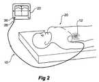
図2は、使用中の図1のガイドワイヤ10を示し、その遠位端12は患者内に配置中であり、その近位端14(使い捨てシース28によって覆われている)は、信号受信器又は発生器装置22に関連する誘導結合器アセンブリ20内に位置している。 FIG. 2 shows the
ガイドワイヤは、臨床医(図示せず)により、ガイドワイヤ12の遠位端がおよそ患者内の所望の位置に位置するまで適切な通路を通じて患者20内に送られる。上述したように、アクセス方法は臨床上の選択である。 The guide wire is routed into the patient 20 through a suitable passageway by a clinician (not shown) until the distal end of the
ガイドワイヤの遠位端を患者内に配置するのを支援するために、ともに本出願人の名義である米国特許第5099845号明細書に開示されている種類の案内装置とPCT/AU2006/000027(国際公開第2006/074510号パンフレット)に開示されている装置及び方法とを使用することができる。排他的にではないが、ガイドワイヤの遠位端に位置する電磁放射素子に対する電磁放射送信又はそこからの電磁放射受信を使用するいかなる装置又は方法も十分である。本実施形態のガイドワイヤ10には、コイルの形態のかかる構成が備えられているが、ほかの場所で論じているように、実際の放射素子は形態が様々である。 In order to assist in positioning the distal end of the guidewire within the patient, a guide device of the type disclosed in US Pat. No. 5,099,845, both in the name of Applicant, and PCT / AU2006 / 00000027 ( The apparatus and method disclosed in WO 2006/074510 (Pamphlet) can be used. Any device or method that uses, but is not exclusively, electromagnetic radiation transmission to or from electromagnetic radiation elements located at the distal end of the guidewire is sufficient. The
信号受信器又は発生器装置22に関連する誘導結合器アセンブリ20については、本明細書において後により詳細に説明する。本明細書のこの部分では、ガイドワイヤの近位端と信号受信器又は発生器装置との間に非接触接続があると言うにとどめる。 The
位置決め構成に関する任意の装置の残り部分は、図面には示されていないが、臨床医がガイドインサートの遠位端を患者内の所望の位置まで案内するのを支援するディスプレイを含んでもよい。 The remaining portion of any device relating to the positioning configuration, although not shown in the drawings, may include a display that assists the clinician in guiding the distal end of the guide insert to a desired location within the patient.
図3は、使用中の図1のガイドインサートを示しており、臨床医がガイドワイヤ10の遠位端16を患者内の所望の位置に配置すると、カテーテル24を患者内に配置するためにガイドインサートの近位端14に配置されている(使い捨てシース28が取り除かれた後)。 FIG. 3 shows the guide insert of FIG. 1 in use, once the clinician has positioned the distal end 16 of the
ガイドインサートは、配置前かつ配置中に無菌状態で維持されるべきであり、それには適切な手順を遵守する必要がある。 The guide insert should be maintained in a sterile condition prior to and during placement, which requires adherence to appropriate procedures.
一例では、無菌シース28がガイドインサートの近位端に組み付けられており、それは、信号受信器又は発生器装置22に関連する非接触誘導結合器アセンブリ20に備わるように意図されている端部である。非接触誘導結合器アセンブリ内部に配置されるシースは、その内部の電磁放射素子の無菌状態を保護する。シースが無菌技法の維持をふまえて取り除かれると、ガイドインサートは、非接触誘導結合器内に挿入される結果、汚染されない。シースの材料、長さ及び形状は、無関係の製品及び装置に対して同様の被覆要件が既知であるため、同様の製品に対して要求される通りである。 In one example, a
ガイドワイヤは、その配置中に結合器アセンブリ内に配置された場合、その最初の挿入後はもはや無菌状態でなくなる。 If the guidewire is placed in the coupler assembly during its placement, it will no longer be sterile after its initial insertion.
ガイドインサートが、位置決めの目的で誘導結合器アセンブリ内に配置された場合、無菌技法の維持をかかるシースなしに達成することができない。 If the guide insert is placed in an inductive coupler assembly for positioning purposes, maintenance of aseptic technique cannot be achieved without such a sheath.
カテーテルが患者内に挿入されている時、ガイドインサートは、カテーテルが「ワイヤ上に」配置される前に処置中に汚染されてはならない。 When the catheter is inserted into the patient, the guide insert must not be contaminated during the procedure before the catheter is placed “on the wire”.
本明細書で開示する1つのオプションは、例えば、略20cm長の1つ又は複数のシースを使用することであり、その内径はガイドワイヤの外径よりわずかに大きく、それは、ガイドワイヤが位置決め装置の誘導結合器内に挿入される前に、ガイドワイヤの近位端に被せて配置される。かかるシースは、製品の組立中に殺菌される。ガイドワイヤが位置決め装置から取り除かれると、シースの外側はそれ以上無菌状態ではなく、その時、無菌領域から離れたところに破棄される。配置処置においてこのステップに続き、カテーテルを、「ワイヤ上に」通すことができ、ワイヤはシースによって保護されていたため、依然として無菌状態である。かかるシースは、製品の組立中に殺菌される。 One option disclosed herein is, for example, to use one or more sheaths that are approximately 20 cm in length, the inner diameter of which is slightly larger than the outer diameter of the guidewire, so that the guidewire is a positioning device. Prior to being inserted into the inductive coupler, it is placed over the proximal end of the guidewire. Such a sheath is sterilized during assembly of the product. When the guide wire is removed from the positioning device, the outside of the sheath is no longer aseptic and is then discarded away from the aseptic area. Following this step in the placement procedure, the catheter can be passed “over the wire” and the wire is still sterile as it was protected by the sheath. Such a sheath is sterilized during assembly of the product.
かかる配置処置におけるいくつかのステップを繰り返す必要のある場合があるため、複数の無菌シースが供給されてもよい。 Multiple sterile sheaths may be provided because some steps in such a placement procedure may need to be repeated.
臨床医に有利なのは、ガイドワイヤに被せて取り付ける必要のあるカテーテル24の長さを確定することができることである。長さの確定は、ガイドインサート(図3には示さず)の長さに沿って位置する1つ又は複数のしるし(indicia)又はマーカを確認することによって容易に達成される。これらのしるし(たとえば、数字、符号化された文字又は数字)又はマーカ(例えば、色及び所定長の帯/バー)は、ガイドインサートの、その遠位端としるし又はマーカとの間の長さを示す。 It is advantageous for the clinician to be able to determine the length of the
しるしによって提供される情報を確認した臨床医は、1つ又は複数の他の要件とともに、患者内に配置されるために必要なカテーテル24の最適な長さを評価することができる。 A clinician who has confirmed the information provided by the indicia, along with one or more other requirements, can evaluate the optimal length of
したがって、利用可能なカテーテルを少なくとも必要な最短長に一致させる処置を、臨床医が行うことができるようにすることができる。 Thus, a clinician may be able to perform a procedure that matches the available catheters to at least the minimum required length.
この明細書はプロトコル又は処置について言及する場合はいつでも、特定のプロトコルが存在することを想定しておらず、臨床医が既存のかつ新たな臨床処置に対して時間の経過により進化する手法を発展させることができることを想定しており、したがって、かかるプロトコルは、臨床環境におけるある一定の機器の実際の使用を反映することが理解される。 Whenever this specification refers to a protocol or treatment, it does not assume that a specific protocol exists, and the clinician develops a method that evolves over time for existing and new clinical treatments. It is understood that such a protocol reflects the actual use of certain instruments in a clinical environment.
有利には、ガイドワイヤ(導電ワイヤ構成16とともに近位端電磁放射素子14を含む)の最大外径は、カテーテル24の最小内径より小さい寸法であるため、カテーテルをガイドワイヤ上に容易に取り付けることができる。したがって、カテーテル24の遠位端26を、ガイドインサートにより患者内の所望の位置まで案内することができる。さらに、ガイドインサートの遠位端12の外径が、本明細書で説明するようにガイドインサートの最大外径と同じか又はそれにより小さいため、カテーテルは、同様にその上にはまり、カテーテルの遠位端を患者内の所望の位置に配置することができ、ガイドインサートをカテーテルから後退させることができる。 Advantageously, because the maximum outer diameter of the guide wire (including the proximal end
図4は、カテーテルの「オーバー・ザ・ガイドワイヤ」配置を示しており、この間、ガイドインサートの遠位端は患者内の所望の位置にあり、ガイドインサートは誘導結合器アセンブリ20内に配置されている。このステップは、すべての場合に必要であるとは限らない。それは、カテーテルによってはその配置が、適切なカテーテル長の知識と各場合における臨床医の技能との組合せによって、所望の位置にあると検証され得るためである。しかしながら、ガイドワイヤ10の近位端14を位置決め機器22(図2)内に誘導結合器アセンブリ20(同様に図2)を介して配置することが可能であるため、カテーテルがガイドワイヤ上でその場にありながら、ガイドインサート10を再び使用してその遠位端12の位置を確認することができる。上述したシース28は近位端上にあり続ける。それは、ガイドワイヤと位置決め装置の誘導結合器アセンブリ20との非接触設計が、シースの存在によって影響を受けないためである。 FIG. 4 shows an “over the guide wire” arrangement of the catheter, during which the distal end of the guide insert is in a desired position within the patient and the guide insert is placed within the
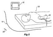
図5は、使用の準備がなされた、患者内の適所にあるカテーテルと、後退したガイドワイヤ10と、を示している。カテーテルの近位端27は、少なくとも2つのさらなる管の接続を可能にするYポート29で終端している。Yポートはまた、2つのポートの開放端を封止するプラグ(図示せず)を有する。かかる終端構成は単に一例であり、実際には多くの多様な終端構成が可能である。 FIG. 5 shows the catheter in place in the patient and the retracted guidewire 10 ready for use. The
図6は、ガイドインサートの近位端を、ロケータ装置22(図示せず)の一部である誘導結合器37で位置決めする構成の一実施形態の断面での機能図を示し、ここでは、ロケータ装置を使用して、ガイドインサートの遠位端の患者内における位置が示される。 FIG. 6 shows a functional diagram in cross-section of one embodiment of a configuration that positions the proximal end of the guide insert with an
図6に示す構成は、結合器とガイドワイヤ上の近位に位置する放射素子との間の電磁エネルギーの誘導交換を可能にするように、ガイドワイヤの近位に位置する電磁放射素子を受け入れかつ位置決めする信号受信器又は発生器装置に関連する誘導結合器のものである。 The configuration shown in FIG. 6 accepts an electromagnetic radiating element located proximal to the guidewire so as to allow inductive exchange of electromagnetic energy between the coupler and the radiating element located proximally on the guidewire. And an inductive coupler associated with the positioning signal receiver or generator device.
図示する機能的構成では、ロケータ装置22(図示せず)の外壁に入口アセンブリが位置しており、入口アセンブリの中心開口は、ガイドワイヤ10の近位端14の挿入が可能な寸法を有する。 In the illustrated functional configuration, an inlet assembly is located on the outer wall of a locator device 22 (not shown), and the central opening of the inlet assembly is dimensioned to allow insertion of the
入口アセンブリを、ロケータ装置22(図示せず)内への開口に隣接しかつそれと同軸に位置する入口アセンブリ30の一部として、プレート31を含むものとして機能的に示す。第2プレート31’もまた内部に通路を有しており、通路に隣接して「O」リング35を配置し、かつガイドインサートがロケータ装置37内に入るために両プレート31及び31’の同軸通路を通して挿入されると、その近位端を包囲するように、形作られることによって適合されている。「O」リング35は、「O」リングを通して摺動可能でありかつ一旦挿入されると通路及びロケータ装置22内に保持されるガイドインサートの近位端の外壁と、摺動可能な締まり嵌めを形成している。「O」リング35とガイドワイヤアセンブリの近位端との間の摺動可能な締まり嵌めはまた、操作者に対し、ガイドワイヤの近位端がロケータ装置内に正しく配置されているという触覚フィードバックも提供する。また、特定の実施形態での「O」リング配置の詳細な図として図7も参照されたい。 The inlet assembly is functionally shown as including a
ガイドワイヤ14の近位端が装置内に挿入されている間、測定を行い、使用者に指示を提供することができる。指示は、放射素子38が、ドライバコイル34と近位に位置する放射素子38との間の電磁エネルギーの最大相互結合に達したという確認を提供する。ロケータ装置22の内部に示すブロック32は、ガイドインサートが入口アセンブリ30を通過してロケータ装置22内に入る際、その近位端の存在を検出することができる少なくとも1つの近接センサを表している。そして、かかる検出により、ガイドインサートが意図された方法で装置22に入っていることを確認することができる。 While the proximal end of
ブロック32は、別法として又はさらに、誘導結合器入口開口を通って配置されたガイドワイヤのタイプを検出してもよい。この機能を、多数の方法で達成することができ、そのうちのいくつかの例は、ガイドインサートの近位端近くに位置するしるし又はマーキングの検出である。特定のガイドインサートの仕様と相関する特性を識別するようにブロック32と相互作用する、1つ又は複数の受動装置又は能動装置が、ガイドインサート上にあってもよく又は組み込まれていてもよい。
ガイドワイヤタイプ、したがってその仕様を識別する情報は、外科処置中に使用される材料の在庫管理プロセス、選択及び追跡性を支援し、使い捨て装置の1回の使用等、制度上のプロトコル及び指針への準拠を確実にする監査プロセスや、もっとも有用には、各患者に対し最も適切なタイプのガイドインサートを選択するプロセスを簡略化するように、ロケータ装置の自動動作に役立つことができる。図示しないが、適切に引き金となるのであれば、ガイドインサートが先に使用されていることを示す機構又は電子装置、例えば、ヒュージブルリンクがあってもよい。そして、好適なプロトコルが、次に行われることを確定するが、機器が特定のガイドワイヤで動作しないようにプログラムされる際、そのガイドワイヤの廃棄を含んでもよい。 Information identifying the guidewire type, and therefore its specifications, supports the inventory management process, selection and traceability of the materials used during the surgical procedure, and to institutional protocols and guidelines such as single use of the disposable device It can help with the automatic operation of the locator device to simplify the audit process to ensure compliance, and most usefully the process of selecting the most appropriate type of guide insert for each patient. Although not shown, there may be a mechanism or electronic device, such as a fusible link, that indicates that the guide insert has been used previously, provided that it triggers properly. The preferred protocol then determines that it will be performed next, but may include discarding that guidewire when the device is programmed to not operate with a particular guidewire.
使用されているガイドワイヤのタイプを知って、有利に制御可能である1つの特性は、近位電磁放射素子を介して遠位電磁放射素子に効率よく信号を送出するために使用する必要のある出力である。それは、それぞれの素子のサイズが、電磁エネルギーを受信/送信するそれらの能力に大幅に影響を与える可能性があるためである。小児科のガイドインサートで使用され得るような寸法の小さいコイル(電磁放射素子の一例である)は、大人の血管位置決め用途で使用され得るようなより大きいコイルからの信号の等価な強度を生成するために必要なエネルギーに比較して、それに送出されるべき必要な電磁エネルギーが大きくなる。 One property that is advantageously controllable knowing the type of guidewire being used must be used to efficiently signal the distal electromagnetic radiating element via the proximal electromagnetic radiating element. Is the output. This is because the size of each element can significantly affect their ability to receive / transmit electromagnetic energy. A small-sized coil (which is an example of an electromagnetic radiating element), such as can be used in pediatric guide inserts, to generate an equivalent strength of the signal from a larger coil, such as can be used in adult vascular positioning applications The required electromagnetic energy to be delivered to it is greater than the required energy.
ブロック34は、電磁エネルギーをガイドワイヤ10の近位端に位置する電磁放射素子に伝達しかつ/又はそこから受け取るために使用される誘導結合器アセンブリ20のドライバコイルである。伝達が非接触であるため、誘導結合器アセンブリは、ガイドインサートの端部と一切接触する必要がない。誘導結合器アセンブリ20の実施形態の構造上かつ動作上の詳細については、本明細書において後により詳細に説明する。
誘導結合器を、用途に応じて電磁エネルギーを伝達し又は受信するように使用可能であることを理解することが重要である。本出願人が所有する、言及した特許に開示されているガイドインサート位置決め機器の使用に関連して、誘導結合器を使用して、電磁エネルギーがガイドワイヤの近位に位置する電磁放射素子に伝達される。それにより、遠位に位置する電磁放射素子は、患者内におけるガイドインサートの遠位端の位置の位置決め確定に役立つ信号を放射することができる。 It is important to understand that inductive couplers can be used to transmit or receive electromagnetic energy depending on the application. In connection with the use of the guide insert positioning device disclosed in the referenced patent owned by the applicant, an inductive coupler is used to transfer electromagnetic energy to an electromagnetic radiating element located proximal to the guide wire. Is done. Thereby, the electromagnetic radiating element located distally can emit a signal that helps to determine the position of the distal end of the guide insert in the patient.
ブロック36は、移動端検出器であり、それは、ドライバコイル34を通過するが依然として誘導結合器アセンブリ20内にあるガイドインサートの近位端の移動を、接触なしに検知する。この種の検出により、ガイドインサートのドライバコイル内へのかつそれを通過する移動を、挿入を行っている使用者に通知することができ、それにより、意図されるように使用される場合、ガイドワイヤの近位端の適切な位置決めにより、端部が、近位に位置する電磁放射素子とドライバコイルとの間の電磁エネルギー伝達を最大限にするように位置することになる。
一実施形態における移動端検出器は、光伝送センサを含み、それは、可視光送信器及び可視光受信器と、関連する回路とを備え、可視光が可視光受信器を横切って移動しているガイドワイヤの近位端の先端によって遮られたことを検出することにより、ガイドワイヤの近位端の正しい位置を検知する。 The moving end detector in one embodiment includes a light transmission sensor, which comprises a visible light transmitter and a visible light receiver and associated circuitry, wherein visible light is moving across the visible light receiver. The correct position of the proximal end of the guide wire is sensed by detecting being blocked by the tip of the proximal end of the guide wire.
誘導結合器アセンブリからの漂遊磁束が、患者内においてガイドインサートの遠位端を位置決めするために使用される遠位で生成された電磁束を干渉すべきでないことを理解することが重要である。したがって、第一に漂遊磁束の発生を最小限にするように設計されている誘導結合器コイルによって発生するいかなる漂遊磁束の漏れも防止するように、誘導結合器の磁気回路を遮蔽することができる。1つの特定の実施形態では、ドライバコイル34は、2層の高透過性ホイルシートを含む磁気シールド33に入れられている。誘導結合器アセンブリケース37は、第2の外部磁気シールドを形成し、それもまた高透過性構造シートから形成されることが好ましく、さらに、高透過性ホイルは内面に使用され、すべての接合部分が導電的に封止されている。 It is important to understand that stray magnetic flux from the inductive coupler assembly should not interfere with the distally generated electromagnetic flux used to position the distal end of the guide insert within the patient. Thus, the magnetic circuit of the inductive coupler can be shielded to prevent any stray flux leakage caused by an inductive coupler coil that is designed to minimize the generation of stray magnetic flux. . In one particular embodiment, the
図7は、図6のより機能的な図と比較した、誘導結合器アセンブリ20内においてガイドワイヤ10の近位端14を位置決めする構成の一実施形態の詳細な断面図を示している。 FIG. 7 shows a detailed cross-sectional view of one embodiment of a configuration for positioning the
アダプタプレート30が、誘導結合器アセンブリ20に対する入口を提供している。アダプタプレート30は、位置決めピン43を介してロケータユニット20の正面パネル31に嵌合しており、この特定の実施形態では、アダプタプレート30はまた、ロケータユニットの正面パネル31の好適に形作られた部分に部分的に位置する「O」リングも保持する。上述したような「O」リングは、ガイドワイヤを挿入している使用者に対し触覚フィードバックを与える手段を提供し、また、ロケータユニット20にガイドインサートが挿入されるとその近位端をそこで保持し、それが偶発的に脱落するのを防止する。ガイドインサートの端部にフィンガグリップ部44が成形されており、それは、ガイドワイヤがロケータユニット20内に配置される際に、使用者がその近位端を保持し配置するのに役立つ。フィンガブリップ部44はまた47において、ガイドインサートが必要以上にロケータユニット内に押し込まれないようにするエンドストップも提供する。 An
図7Aに、近接・色センサブロック32の断面細部を示す。3色送信機発光ダイオード(LED)51が、導光素子55を通して光を照射し、それは、ガイドインサートアセンブリ10の本体から第2導光素子56を介して光検出センサ53に反射され、その反射光が、ガイドインサートアセンブリ10の外部本体のフィルタ効果の結果である。それにより、2つ以上の色を検出することができ、したがってこの実施形態では、装置がその色をガイドインサートアセンブリの特定のタイプと関連付けることができる特定の色を検出したセンサによって、本体(したがってガイドインサートタイプ)を識別することができる。ガイドインサートアセンブリが識別可能であることが有用であり、そうでなければ、ガイドインサートアセンブリの動作を制御する自動設定のうちのいくつかが不適切となり、結果が不正確な位置出力である可能性がある。 FIG. 7A shows a cross-sectional detail of the proximity /
可視光検出システムの2つの追加の特徴は、領域57における固体面が、すべての色を反射するように白色であり、これにより、色検知システムが、ガイドインサートが誘導結合器アセンブリケースに挿入され又はそこから取り除かれたことを明確に知ることができる。さらに、本システムは、送信機LEDを順に各原色に切り替え、センサ53において適切な応答を検出することにより各々が機能していることを検証することによって、特定の構成要素が故障しているか試験することができる。 Two additional features of the visible light detection system are that the solid surface in
センサブロック32の動作のさらなるモードは、ガイドインサートアセンブリの本体が誘導結合器アセンブリケース内に挿入される際に、色又は明るさの変化を監視するというものである。これにより、一例では一連の色付き帯によりガイドインサート本体上に符号化されている情報を、必要に応じて読み取りかつ解釈することが可能になる。 A further mode of operation of the
信号受信器又は発生器に関連する誘導結合器は、一実施形態では、ボビン48に巻回されたワイヤのコイル等のインダクタ素子として設けられている。これは、カテーテルの近位に位置する装置と電磁エネルギーを交換するために使用可能な単なる1つの代替装置である。ボビン48は、前者として作用し、その周囲にワイヤを巻き付けることができ、ガイドワイヤ10の近位に位置する電磁放射素子に電磁エネルギーを伝達しかつそこから電磁エネルギーを収集するように使用可能である。インダクタ用ボビン及びコイル巻線に関するさらなる詳細は、本明細書において後に提供する。 The inductive coupler associated with the signal receiver or generator is provided in one embodiment as an inductor element, such as a coil of wire wound around a
すべての素子32、33、36、40、48及び44は、ガイドインサート10が通過する中心通路を有し、それにより、ガイドインサートの最近位端が、移動端検出器構成を提供する上述した透過性フォトマイクロセンサ49を含むブロック36内に入ることができる。 All
ボビンを中心にかつその端部の周囲にシールド33が位置しており、それは、電磁的に遮蔽された筐体内にガイドワイヤ10の近位に位置する端部が入るのを可能にする孔を有している。上述したシールド33は、この実施形態では、絶縁材料の薄層により相互に電気的に絶縁されている2層の高透過性ホイルを有している。 A
図8は、ドライバコイルの一実施形態を示す。ドライバコイルは、2つの半体61及び62から形成されているシングルエンドコイルであり、それら両半体は、それらの2つの内端に共通箇所60を有し、外端において駆動される。2つのコイル巻線半体は、反対方向に巻回されており、中心隔壁63を用いて、巻線の各半体が別個に巻回されることが可能である。 FIG. 8 shows an embodiment of the driver coil. The driver coil is a single-ended coil formed from two
コイルの構成により、駆動ノードに直接接続されている外部コイル層間のコイル径を横切る間隔があることが確実となり、それにより、駆動ノードとガイドワイヤの電磁放射素子との間の共通モード電圧の容量結合が最小になる。この構成により、電磁放射素子に最も近い最内巻線層に現れる共通モード駆動電圧が最小であることも確実になる。説明したコイル設計により、ガイドインサートアセンブリのいかなる導電部分に対する共通モード同期信号の振幅も低減し、そうでなければ、これら信号は、信号検出システム内に放射され、位置測定において、特に磁気信号強度が低く望ましくない放射信号が顕著になる可能性のある長距離において、誤りをもたらす可能性がある。 The coil configuration ensures that there is a spacing across the coil diameter between the outer coil layers directly connected to the drive node, thereby allowing the common mode voltage capacitance between the drive node and the guidewire electromagnetic radiation element. Coupling is minimized. This configuration also ensures that the common mode drive voltage appearing in the innermost winding layer closest to the electromagnetic radiation element is minimal. The described coil design reduces the amplitude of the common mode-locking signal for any conductive part of the guide insert assembly, otherwise these signals are radiated into the signal detection system, especially in position measurements where the magnetic signal strength is reduced. At long distances where low and undesired radiated signals can become noticeable, it can lead to errors.
指示される物理的寸法、インダクタンス値、ワイヤ巻数及びワイヤゲージは、この実施形態では以下の通りであり、それらが提供される場合、本システム及びアセンブリの位置検出機能を駆動するために必要な信号強度出力、結合係数、効率及び精度が得られることとなる。 The indicated physical dimensions, inductance values, wire turns and wire gauge are as follows in this embodiment and, if provided, the signals required to drive the position sensing function of the system and assembly: Strength output, coupling coefficient, efficiency and accuracy will be obtained.
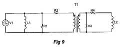
図9は、誘導結合器構成に対する等価回路を示しており、そこでは、電磁エネルギー伝達は損失のある変圧器のように作用し、結合計算は、それに従って関連素子を扱う。 FIG. 9 shows an equivalent circuit for an inductive coupler configuration in which electromagnetic energy transfer acts like a lossy transformer and the coupling calculation handles the associated elements accordingly.
図における「ドライバ」コイル及び「結合」コイルという用語の使用は、コイルのあり得る目的の単なる1つのバージョンに関連するものであり、それらの機能は本発明の別の実施形態において逆にすることができる。 The use of the terms “driver” coil and “coupled” coil in the figures relate to just one version of the coil's possible purpose, and their functions are reversed in another embodiment of the invention. Can do.
図10は、ガイドワイヤの遠位端からの電磁放射についての信号を提供する誘導結合器に信号を供給する信号ドライバ回路を示している。 FIG. 10 shows a signal driver circuit that provides a signal to an inductive coupler that provides a signal for electromagnetic radiation from the distal end of the guidewire.
コイルに対する駆動は、インピーダンス及びタイミングが対称でなければならず、そうでなければ、受信器コイルに関連してガイドワイヤの遠位に位置する電磁放射素子の角度向きの変化のために、電磁信号位相が反転する位置において、誤りが発生する可能性がある。コイルに対する駆動がインピーダンス及びタイミングにおいて対称であるためには、図10の回路に示すような素子143〜150を備えるデュアルハーフブリッジドライバが使用される。ドライブコイル151への信号振幅出力は、可変DC電圧源141によって制御される。信号入力152及び153は、2つのハーフブリッジドライブからの出力を同期させる2つのオーバラップしない時間対称駆動信号を含む。ハーフブリッジドライブへの供給電流は、電流検知抵抗器154及び増幅器142を含む電流センサによって監視される。 The drive to the coil must be symmetric in impedance and timing, otherwise electromagnetic signals due to changes in the angular orientation of the electromagnetic radiating element located distal to the guidewire relative to the receiver coil. An error may occur at a position where the phase is reversed. In order for the drive to the coil to be symmetric in impedance and timing, a dual half bridge driver with elements 143 to 150 as shown in the circuit of FIG. 10 is used. The signal amplitude output to the drive coil 151 is controlled by the variable
電流センサ回路は、ドライバコイル電流に比例する出力を提供する。ドライバコイル電流及びドライバコイル電圧を監視し、適切な計算を行うことにより、以下の複数の目標を達成することができる。
a)二次コイルへ従って送信器コイル内へ駆動されるエネルギーの量を制御することができる。これにより、ドライバは、異なる目的に対し(小児科で使用するためのより小さいガイドワイヤ等)異なるガイドインサートに対応することができる。
b)ドライバは、製造工程における変動によってもたらされるガイドインサートの抵抗の変動をある程度まで補償することができる。
c)二次回路のインピーダンスを推断することができ、これにより、開回路状態及び短絡状態等、ガイドインサートの特性の検出が可能になる。The current sensor circuit provides an output that is proportional to the driver coil current. By monitoring the driver coil current and driver coil voltage and making appropriate calculations, the following goals can be achieved.
a) The amount of energy driven into the secondary coil and thus into the transmitter coil can be controlled. This allows the driver to accommodate different guide inserts for different purposes (such as smaller guidewires for use in pediatrics).
b) The driver can compensate to some extent for variations in guide insert resistance caused by variations in the manufacturing process.
c) The impedance of the secondary circuit can be inferred, which makes it possible to detect the characteristics of the guide insert, such as an open circuit state and a short circuit state.
図11は、図12の回路を使用して電磁放射素子ドライバコイル151を駆動するために好適なパルス幅変調タイミング方式を示しており、図12の回路は、与えられている例では、必要な周波数において実質的に正弦波形を生成するように意図している。 FIG. 11 illustrates a preferred pulse width modulation timing scheme for driving the electromagnetic radiating element driver coil 151 using the circuit of FIG. 12, and the circuit of FIG. It is intended to produce a substantially sinusoidal waveform at frequency.
正弦波励起により一次コイルを駆動することは、以下のような複数の利点があるため好ましい。
a)望ましくない高調波を低減又は除去することによりEMIが最小化する
b)上記と同じ理由で効率が最大化する
c)この場合もまた同じ理由で、二次コイル及び送信器コイルにおいて渦電流加熱が低減する。Driving the primary coil by sinusoidal excitation is preferable because of the following advantages.
a) Minimizing or eliminating unwanted harmonics to minimize EMI b) Maximizing efficiency for the same reasons c) Again, for the same reasons, eddy currents in the secondary and transmitter coils Heating is reduced.
これを達成する1つの方法は、図10にも示すように、並列コンデンサ155を使用してドライバコイル151のインダクタンスとともに共振回路を形成するというものである。 One way to achieve this is to use a
しかしながら、かかる構成には以下のような欠点がある。
a)それは、固定動作周波数に関連し、周波数が変化する場合に回路値を調整しなければならない
b)部品定数が、一次コイルの動作周波数及び物理的形状/配置によって決まり、これには、容易に入手できないか、又はさらには入手可能でない部品定数が必要となり得る
c)信号ドライバは、部品の製造における変動によってもたらされる一次コイルの変動に対し自動的に適合することができない
d)本明細書で開示した実施形態に特異的で、同調回路のQを非常に高くすることができず、そうでない場合、ゲイン及び位相安定性に対し悪影響があり得る。However, this configuration has the following drawbacks.
a) it is related to a fixed operating frequency, the circuit value must be adjusted if the frequency changes b) the component constant depends on the operating frequency and physical shape / arrangement of the primary coil, which is easy C) Signal drivers may not be able to automatically adapt to variations in the primary coil caused by variations in the manufacture of the components. Specific to the embodiment disclosed in, the Q of the tuning circuit cannot be very high, otherwise it can have a negative impact on gain and phase stability.
したがって、図12に関連して開示するようなPWM方式の使用が、製造変動に影響を受けない周波数での動作を可能にすることによって、上述した問題を低減し又は除去することに役立つことができる。 Thus, the use of a PWM scheme as disclosed in connection with FIG. 12 may help to reduce or eliminate the above-described problems by allowing operation at frequencies that are not affected by manufacturing variations. it can.
図12は、図10に示す回路に関連して説明したものと同様に動作する、本発明の一実施形態で使用されるパルス幅変調信号駆動回路を示している。 FIG. 12 illustrates a pulse width modulated signal drive circuit used in one embodiment of the present invention that operates similar to that described in connection with the circuit shown in FIG.
当業者には、本発明が、説明した特定の用途に向けた使用に限定されないことが理解されよう。本発明は、本明細書で説明し又は図示した特定の要素及び/又は特徴に関してその好ましい実施形態に限定されるものでもない。本発明の原理から逸脱することなく、さまざまな変更を行うことができることが理解されよう。したがって、本発明は、その範囲内にかかる変更をすべて包含することが理解されるべきである。 Those skilled in the art will appreciate that the present invention is not limited to use for the particular application described. The invention is not limited to the preferred embodiments thereof with respect to the specific elements and / or features described or illustrated herein. It will be understood that various modifications can be made without departing from the principles of the invention. Accordingly, it is to be understood that the invention includes all such modifications within its scope.
Claims (18)
Translated fromJapanese遠位に位置する電磁放射素子と、
近位に位置する電磁放射素子と、
前記遠位に位置する電磁放射素子及び前記近位に位置する電磁放射素子を接続する導電ワイヤ構成と
を具備する、ガイドインサートアセンブリ。A guide insert assembly having a distal end and a proximal end comprising:
An electromagnetic radiation element located distally;
An electromagnetic radiation element located proximally;
A guide insert assembly comprising a distally located electromagnetic radiating element and a conductive wire arrangement connecting the proximally located electromagnetic radiating element.
遠位端及び近位端を有しており、遠位に位置する電磁放射素子、近位に位置する電磁放射素子、並びに前記遠位に位置する電磁放射素子及び前記近位に位置する電磁放射素子を接続する導電ワイヤ構成を備えるガイドインサートアセンブリと、
信号受信器又は発生器に関連する誘導結合器であって、前記遠位に位置する電磁放射素子への伝送のために、前記結合器と前記近位に位置する放射素子との間の電磁エネルギーの誘導交換を可能にするように、ガイドワイヤの近位端を受け入れるように適合された誘電結合器と
を具備する、ガイドインサート信号誘導結合構成。Guide insert signal inductive coupling configuration,
A distally located and proximally located electromagnetic radiating element, a proximally located electromagnetic radiating element, and said distally located electromagnetic radiating element and said proximally located electromagnetic radiation A guide insert assembly with a conductive wire configuration connecting the elements;
An inductive coupler associated with a signal receiver or generator, the electromagnetic energy between the coupler and the proximally located radiating element for transmission to the distally located electromagnetic radiating element A guide insert signal inductive coupling arrangement comprising a dielectric coupler adapted to receive a proximal end of a guide wire to allow inductive exchange of the guide wire.
ガイドワイヤ材料のタイプ、
導電ワイヤアセンブリの抵抗、又は
前記誘導結合器装置に対する前記近位に位置する電磁放射素子の位置
を含む、請求項13に記載のガイドインサートアセンブリ。The predetermined characteristic is
Type of guidewire material,
14. A guide insert assembly according to claim 13, comprising the resistance of a conductive wire assembly or the position of the proximally located electromagnetic radiating element relative to the inductive coupler device.
前記誘導結合器の又は前記ガイドインサートアセンブリの前記電磁放射素子との開回路又は短絡を含む、前記ガイドワイヤアセンブリの異常を検出するインピーダンス測定装置
をさらに有する、請求項1に記載のガイドインサートアセンブリ。The inductive coupler comprises:
The guide insert assembly of claim 1, further comprising an impedance measurement device that detects an anomaly of the guidewire assembly, including an open circuit or a short circuit of the inductive coupler or of the guide insert assembly with the electromagnetic radiating element.
前記誘導結合器の誘導結合による結合の有効性を示す、前記ガイドワイヤアセンブリの前記電磁放射素子の特性を検出するインピーダンス測定装置
をさらに有する、請求項1に記載のガイドインサートアセンブリ。The inductive coupler comprises:
The guide insert assembly of claim 1, further comprising an impedance measurement device that detects a property of the electromagnetic radiating element of the guidewire assembly that indicates the effectiveness of inductive coupling of the inductive coupler.
前記ガイドインサートアセンブリの材料におけるインピーダンスが関連する異常を検出するインピーダンス測定装置
をさらに有する、請求項1に記載のガイドインサートアセンブリ。The inductive coupler comprises:
The guide insert assembly of claim 1, further comprising an impedance measurement device that detects an anomaly associated with an impedance in a material of the guide insert assembly.
Applications Claiming Priority (2)
| Application Number | Priority Date | Filing Date | Title |
|---|---|---|---|
| AU2006904933AAU2006904933A0 (en) | 2006-09-08 | Guide-wire and guiding insert placement assembly for over-the-wire catheter placement and method of use | |
| PCT/AU2007/001332WO2008028253A1 (en) | 2006-09-08 | 2007-09-07 | Guide-wire and guiding insert placement assembly for over-the-wire catheter placement and method of use |
Publications (1)
| Publication Number | Publication Date |
|---|---|
| JP2010502314Atrue JP2010502314A (en) | 2010-01-28 |
Family
ID=39156752
Family Applications (1)
| Application Number | Title | Priority Date | Filing Date |
|---|---|---|---|
| JP2009526988APendingJP2010502314A (en) | 2006-09-08 | 2007-09-07 | Guide wire and guide insert placement assembly for over-the-wire catheter placement and methods of use |
Country Status (6)
| Country | Link |
|---|---|
| US (1) | US20100036284A1 (en) |
| EP (1) | EP2089090A4 (en) |
| JP (1) | JP2010502314A (en) |
| AU (1) | AU2007294408B2 (en) |
| CA (1) | CA2662883A1 (en) |
| WO (1) | WO2008028253A1 (en) |
Cited By (1)
| Publication number | Priority date | Publication date | Assignee | Title |
|---|---|---|---|---|
| JP2010524581A (en)* | 2007-04-16 | 2010-07-22 | シー・アール・バード・インコーポレーテッド | Guidewire-assisted catheter positioning system |
Families Citing this family (42)
| Publication number | Priority date | Publication date | Assignee | Title |
|---|---|---|---|---|
| US8784336B2 (en) | 2005-08-24 | 2014-07-22 | C. R. Bard, Inc. | Stylet apparatuses and methods of manufacture |
| US8388546B2 (en) | 2006-10-23 | 2013-03-05 | Bard Access Systems, Inc. | Method of locating the tip of a central venous catheter |
| US7794407B2 (en) | 2006-10-23 | 2010-09-14 | Bard Access Systems, Inc. | Method of locating the tip of a central venous catheter |
| US8849382B2 (en) | 2007-11-26 | 2014-09-30 | C. R. Bard, Inc. | Apparatus and display methods relating to intravascular placement of a catheter |
| US10751509B2 (en) | 2007-11-26 | 2020-08-25 | C. R. Bard, Inc. | Iconic representations for guidance of an indwelling medical device |
| ES2465915T3 (en) | 2007-11-26 | 2014-06-09 | C.R. Bard, Inc. | Integrated system for intravascular catheter placement |
| US9649048B2 (en) | 2007-11-26 | 2017-05-16 | C. R. Bard, Inc. | Systems and methods for breaching a sterile field for intravascular placement of a catheter |
| US10449330B2 (en) | 2007-11-26 | 2019-10-22 | C. R. Bard, Inc. | Magnetic element-equipped needle assemblies |
| US8781555B2 (en) | 2007-11-26 | 2014-07-15 | C. R. Bard, Inc. | System for placement of a catheter including a signal-generating stylet |
| US9636031B2 (en) | 2007-11-26 | 2017-05-02 | C.R. Bard, Inc. | Stylets for use with apparatus for intravascular placement of a catheter |
| US9521961B2 (en) | 2007-11-26 | 2016-12-20 | C. R. Bard, Inc. | Systems and methods for guiding a medical instrument |
| US10524691B2 (en) | 2007-11-26 | 2020-01-07 | C. R. Bard, Inc. | Needle assembly including an aligned magnetic element |
| US8478382B2 (en) | 2008-02-11 | 2013-07-02 | C. R. Bard, Inc. | Systems and methods for positioning a catheter |
| US9901714B2 (en) | 2008-08-22 | 2018-02-27 | C. R. Bard, Inc. | Catheter assembly including ECG sensor and magnetic assemblies |
| US8437833B2 (en) | 2008-10-07 | 2013-05-07 | Bard Access Systems, Inc. | Percutaneous magnetic gastrostomy |
| JP5795576B2 (en) | 2009-06-12 | 2015-10-14 | バード・アクセス・システムズ,インコーポレーテッド | Method of operating a computer-based medical device that uses an electrocardiogram (ECG) signal to position an intravascular device in or near the heart |
| US9532724B2 (en) | 2009-06-12 | 2017-01-03 | Bard Access Systems, Inc. | Apparatus and method for catheter navigation using endovascular energy mapping |
| EP2464407A4 (en) | 2009-08-10 | 2014-04-02 | Bard Access Systems Inc | Devices and methods for endovascular electrography |
| WO2011044421A1 (en) | 2009-10-08 | 2011-04-14 | C. R. Bard, Inc. | Spacers for use with an ultrasound probe |
| WO2011097312A1 (en) | 2010-02-02 | 2011-08-11 | C.R. Bard, Inc. | Apparatus and method for catheter navigation and tip location |
| EP4122385A1 (en) | 2010-05-28 | 2023-01-25 | C. R. Bard, Inc. | Insertion guidance system for needles and medical components |
| EP2912999B1 (en) | 2010-05-28 | 2022-06-29 | C. R. Bard, Inc. | Apparatus for use with needle insertion guidance system |
| CN103228219B (en) | 2010-08-09 | 2016-04-27 | C·R·巴德股份有限公司 | Support and Covering Structures for Ultrasound Probe Heads |
| BR112013002431B1 (en) | 2010-08-20 | 2021-06-29 | C.R. Bard, Inc | SYSTEM FOR RECONFIRMING THE POSITION OF A CATHETER INSIDE A PATIENT |
| US8801693B2 (en) | 2010-10-29 | 2014-08-12 | C. R. Bard, Inc. | Bioimpedance-assisted placement of a medical device |
| RU2609203C2 (en) | 2011-07-06 | 2017-01-30 | Си.Ар. Бард, Инк. | Determination and calibration of needle length for needle guidance system |
| USD699359S1 (en) | 2011-08-09 | 2014-02-11 | C. R. Bard, Inc. | Ultrasound probe head |
| US10258255B2 (en)* | 2011-09-14 | 2019-04-16 | St. Jude Medical International Holding S.àr.l. | Method for producing a miniature electromagnetic coil using flexible printed circuitry |
| US9211107B2 (en) | 2011-11-07 | 2015-12-15 | C. R. Bard, Inc. | Ruggedized ultrasound hydrogel insert |
| US8663116B2 (en)* | 2012-01-11 | 2014-03-04 | Angiodynamics, Inc. | Methods, assemblies, and devices for positioning a catheter tip using an ultrasonic imaging system |
| EP2861153A4 (en) | 2012-06-15 | 2016-10-19 | Bard Inc C R | Apparatus and methods for detection of a removable cap on an ultrasound probe |
| CA2887877A1 (en)* | 2012-10-18 | 2014-04-24 | C.R. Bard, Inc. | Magnetic element-equipped needle assemblies |
| EP3050214B1 (en) | 2013-09-25 | 2019-03-20 | Georgia Tech Research Corporation | Mri compatible 3-d intracardiac echography catheter and system |
| WO2015120256A2 (en) | 2014-02-06 | 2015-08-13 | C.R. Bard, Inc. | Systems and methods for guidance and placement of an intravascular device |
| US20150282734A1 (en) | 2014-04-08 | 2015-10-08 | Timothy Schweikert | Medical device placement system and a method for its use |
| US10973584B2 (en) | 2015-01-19 | 2021-04-13 | Bard Access Systems, Inc. | Device and method for vascular access |
| WO2016210325A1 (en) | 2015-06-26 | 2016-12-29 | C.R. Bard, Inc. | Connector interface for ecg-based catheter positioning system |
| US10067007B2 (en) | 2015-09-02 | 2018-09-04 | Oculus Vr, Llc | Resistive-capacitive deformation sensor |
| US11000207B2 (en) | 2016-01-29 | 2021-05-11 | C. R. Bard, Inc. | Multiple coil system for tracking a medical device |
| US10874451B2 (en) | 2016-02-29 | 2020-12-29 | Pulse Biosciences, Inc. | High-voltage analog circuit pulser and pulse generator discharge circuit |
| CN108379734B (en)* | 2018-05-14 | 2022-04-01 | 上海肤泰科技有限公司 | Regional transdermal iontophoresis drug delivery system |
| US10992079B2 (en) | 2018-10-16 | 2021-04-27 | Bard Access Systems, Inc. | Safety-equipped connection systems and methods thereof for establishing electrical connections |
Family Cites Families (11)
| Publication number | Priority date | Publication date | Assignee | Title |
|---|---|---|---|---|
| US5370675A (en)* | 1992-08-12 | 1994-12-06 | Vidamed, Inc. | Medical probe device and method |
| US4905698A (en)* | 1988-09-13 | 1990-03-06 | Pharmacia Deltec Inc. | Method and apparatus for catheter location determination |
| CN1049287A (en)* | 1989-05-24 | 1991-02-20 | 住友电气工业株式会社 | The treatment conduit |
| US5084022A (en)* | 1989-10-04 | 1992-01-28 | Lake Region Manufacturing Company, Inc. | Graduated guidewire |
| US5437277A (en)* | 1991-11-18 | 1995-08-01 | General Electric Company | Inductively coupled RF tracking system for use in invasive imaging of a living body |
| US6605049B1 (en)* | 2000-12-21 | 2003-08-12 | Advanced Cardiovascular Systems, Inc. | Marking system and method for medical devices |
| US7182735B2 (en)* | 2003-02-26 | 2007-02-27 | Scimed Life Systems, Inc. | Elongated intracorporal medical device |
| DE102004058008B4 (en)* | 2004-12-01 | 2007-08-23 | Siemens Ag | Guidewire for vascular catheter with improved tracking and navigation |
| EP1843810A1 (en)* | 2005-01-14 | 2007-10-17 | Micronix Pty Ltd | Guiding insert assembly for a catheter used with a catheter position guidance system |
| US8784336B2 (en)* | 2005-08-24 | 2014-07-22 | C. R. Bard, Inc. | Stylet apparatuses and methods of manufacture |
| US20070208251A1 (en)* | 2006-03-02 | 2007-09-06 | General Electric Company | Transformer-coupled guidewire system and method of use |
- 2007
- 2007-09-07JPJP2009526988Apatent/JP2010502314A/enactivePending
- 2007-09-07EPEP07800286Apatent/EP2089090A4/ennot_activeWithdrawn
- 2007-09-07WOPCT/AU2007/001332patent/WO2008028253A1/enactiveApplication Filing
- 2007-09-07USUS12/440,372patent/US20100036284A1/ennot_activeAbandoned
- 2007-09-07AUAU2007294408Apatent/AU2007294408B2/ennot_activeCeased
- 2007-09-07CACA002662883Apatent/CA2662883A1/ennot_activeAbandoned
Cited By (1)
| Publication number | Priority date | Publication date | Assignee | Title |
|---|---|---|---|---|
| JP2010524581A (en)* | 2007-04-16 | 2010-07-22 | シー・アール・バード・インコーポレーテッド | Guidewire-assisted catheter positioning system |
Also Published As
| Publication number | Publication date |
|---|---|
| AU2007294408B2 (en) | 2013-06-13 |
| WO2008028253A1 (en) | 2008-03-13 |
| EP2089090A1 (en) | 2009-08-19 |
| US20100036284A1 (en) | 2010-02-11 |
| EP2089090A4 (en) | 2012-12-05 |
| CA2662883A1 (en) | 2008-03-13 |
| AU2007294408A1 (en) | 2008-03-13 |
Similar Documents
| Publication | Publication Date | Title |
|---|---|---|
| JP2010502314A (en) | Guide wire and guide insert placement assembly for over-the-wire catheter placement and methods of use | |
| US12193805B2 (en) | Magnetic field generator with minimal image occlusion and minimal impact on dimensions in C-arm x-ray environments | |
| JP6830911B2 (en) | Surgical systems and devices for percutaneous creation of autologous vascularized subcutaneous arteriovenous fistula (AVF) | |
| US10493235B2 (en) | Reducing mechanical stress on conductors and connection points in a position determinable interventional medical device | |
| JP6209669B2 (en) | System for detecting catheter electrode entry and exit from an introducer | |
| US20110098559A1 (en) | Guiding insert assembly for a catheter used with a catheter position guidance system | |
| US5727553A (en) | Catheter with integral electromagnetic location identification device | |
| NL1021183C2 (en) | Catheter with integrated signal processing device. | |
| US20100168555A1 (en) | Interventional devices for chronic total occlusion recanalization under MRI guidance | |
| JP2015091325A (en) | Vascular access and guidance system | |
| JP5848347B2 (en) | Removable navigation system and method for medical devices | |
| JP2016533785A (en) | Intravascular device, system, and method | |
| JP2008532569A (en) | Tubular assembly and signal generator positioning apparatus and method for use with a catheter guidance system | |
| WO2008031025A2 (en) | Medical device position guidance system with wireless connectivity between a noninvasive device and an invasive device | |
| WO2023006075A1 (en) | Puncture instrument | |
| JP2022542250A (en) | Medical device location notification system | |
| JP2020508758A (en) | Intravascular detection device with flexible tip structure | |
| WO2016200334A1 (en) | System and method for determining the position of inserted medical tubes | |
| US20210030628A1 (en) | Medical Device Position Notification System | |
| CN114375213A (en) | Device and method for guidewire placement | |
| US20230381456A1 (en) | Catheter exchange strategy and catheter configured for same | |
| US20240366311A1 (en) | Medical instrument position sensor sleeve with integral heating element | |
| WO2019116313A1 (en) | Guidewire assembly with offset core wires | |
| WO2024228065A1 (en) | Medical instrument position sensor sleeve with integral heating element | |
| EP3952738A1 (en) | System and method for medical device position guidance |