JP2010501275A - Method of manufacturing an oscillating tip surgical saw blade - Google Patents
Method of manufacturing an oscillating tip surgical saw bladeDownload PDFInfo
- Publication number
- JP2010501275A JP2010501275AJP2009525717AJP2009525717AJP2010501275AJP 2010501275 AJP2010501275 AJP 2010501275AJP 2009525717 AJP2009525717 AJP 2009525717AJP 2009525717 AJP2009525717 AJP 2009525717AJP 2010501275 AJP2010501275 AJP 2010501275A
- Authority
- JP
- Japan
- Prior art keywords
- plate
- blade
- boss
- plates
- welding
- Prior art date
- Legal status (The legal status is an assumption and is not a legal conclusion. Google has not performed a legal analysis and makes no representation as to the accuracy of the status listed.)
- Pending
Links
- 238000000034methodMethods0.000claimsabstractdescription114
- 238000003466weldingMethods0.000claimsabstractdescription43
- 230000008569processEffects0.000claimsdescription38
- 238000004080punchingMethods0.000claimsdescription12
- 238000000465mouldingMethods0.000claimsdescription9
- 238000007493shaping processMethods0.000claims1
- 238000001356surgical procedureMethods0.000claims1
- 229910052751metalInorganic materials0.000description33
- 239000002184metalSubstances0.000description33
- 230000002093peripheral effectEffects0.000description13
- 239000000463materialSubstances0.000description11
- 238000005520cutting processMethods0.000description9
- 230000007246mechanismEffects0.000description8
- 210000005069earsAnatomy0.000description7
- 238000004519manufacturing processMethods0.000description6
- 230000035515penetrationEffects0.000description6
- 238000007514turningMethods0.000description6
- 230000007704transitionEffects0.000description5
- 230000000295complement effectEffects0.000description4
- 238000012546transferMethods0.000description4
- 229910001220stainless steelInorganic materials0.000description3
- 239000010935stainless steelSubstances0.000description3
- XEEYBQQBJWHFJM-UHFFFAOYSA-NIronChemical compound[Fe]XEEYBQQBJWHFJM-UHFFFAOYSA-N0.000description2
- 230000008901benefitEffects0.000description2
- 230000015572biosynthetic processEffects0.000description2
- 238000005530etchingMethods0.000description2
- 238000003754machiningMethods0.000description2
- 238000003825pressingMethods0.000description2
- 229910000984420 stainless steelInorganic materials0.000description1
- OKTJSMMVPCPJKN-UHFFFAOYSA-NCarbonChemical compound[C]OKTJSMMVPCPJKN-UHFFFAOYSA-N0.000description1
- VYZAMTAEIAYCRO-UHFFFAOYSA-NChromiumChemical compound[Cr]VYZAMTAEIAYCRO-UHFFFAOYSA-N0.000description1
- OAICVXFJPJFONN-UHFFFAOYSA-NPhosphorusChemical compound[P]OAICVXFJPJFONN-UHFFFAOYSA-N0.000description1
- 229910000831SteelInorganic materials0.000description1
- NINIDFKCEFEMDL-UHFFFAOYSA-NSulfurChemical compound[S]NINIDFKCEFEMDL-UHFFFAOYSA-N0.000description1
- 230000002411adverseEffects0.000description1
- 229910052799carbonInorganic materials0.000description1
- 229910052804chromiumInorganic materials0.000description1
- 239000011651chromiumSubstances0.000description1
- 238000004140cleaningMethods0.000description1
- 238000010276constructionMethods0.000description1
- 230000008878couplingEffects0.000description1
- 238000010168coupling processMethods0.000description1
- 238000005859coupling reactionMethods0.000description1
- 238000009792diffusion processMethods0.000description1
- 238000010894electron beam technologyMethods0.000description1
- 238000003780insertionMethods0.000description1
- 230000037431insertionEffects0.000description1
- 229910052742ironInorganic materials0.000description1
- WPBNNNQJVZRUHP-UHFFFAOYSA-Lmanganese(2+);methyl n-[[2-(methoxycarbonylcarbamothioylamino)phenyl]carbamothioyl]carbamate;n-[2-(sulfidocarbothioylamino)ethyl]carbamodithioateChemical compound[Mn+2].[S-]C(=S)NCCNC([S-])=S.COC(=O)NC(=S)NC1=CC=CC=C1NC(=S)NC(=O)OCWPBNNNQJVZRUHP-UHFFFAOYSA-L0.000description1
- 239000000203mixtureSubstances0.000description1
- 238000012986modificationMethods0.000description1
- 230000004048modificationEffects0.000description1
- NJPPVKZQTLUDBO-UHFFFAOYSA-NnovaluronChemical compoundC1=C(Cl)C(OC(F)(F)C(OC(F)(F)F)F)=CC=C1NC(=O)NC(=O)C1=C(F)C=CC=C1FNJPPVKZQTLUDBO-UHFFFAOYSA-N0.000description1
- 229910052698phosphorusInorganic materials0.000description1
- 239000011574phosphorusSubstances0.000description1
- 238000007517polishing processMethods0.000description1
- 238000012545processingMethods0.000description1
- 230000000750progressive effectEffects0.000description1
- 230000009467reductionEffects0.000description1
- 230000003014reinforcing effectEffects0.000description1
- 229910052710siliconInorganic materials0.000description1
- 239000010703siliconSubstances0.000description1
- 238000009751slip formingMethods0.000description1
- 239000010959steelSubstances0.000description1
- 239000000126substanceSubstances0.000description1
- 229910052717sulfurInorganic materials0.000description1
- 239000011593sulfurSubstances0.000description1
- 230000036346tooth eruptionEffects0.000description1
- 238000009763wire-cut EDMMethods0.000description1
Images


Classifications
- A—HUMAN NECESSITIES
- A61—MEDICAL OR VETERINARY SCIENCE; HYGIENE
- A61B—DIAGNOSIS; SURGERY; IDENTIFICATION
- A61B17/00—Surgical instruments, devices or methods
- A61B17/14—Surgical saws
- A61B17/142—Surgical saws with reciprocating saw blades, e.g. with cutting edges at the distal end of the saw blades
- A—HUMAN NECESSITIES
- A61—MEDICAL OR VETERINARY SCIENCE; HYGIENE
- A61B—DIAGNOSIS; SURGERY; IDENTIFICATION
- A61B17/00—Surgical instruments, devices or methods
- A61B2017/00526—Methods of manufacturing
- Y—GENERAL TAGGING OF NEW TECHNOLOGICAL DEVELOPMENTS; GENERAL TAGGING OF CROSS-SECTIONAL TECHNOLOGIES SPANNING OVER SEVERAL SECTIONS OF THE IPC; TECHNICAL SUBJECTS COVERED BY FORMER USPC CROSS-REFERENCE ART COLLECTIONS [XRACs] AND DIGESTS
- Y10—TECHNICAL SUBJECTS COVERED BY FORMER USPC
- Y10T—TECHNICAL SUBJECTS COVERED BY FORMER US CLASSIFICATION
- Y10T29/00—Metal working
- Y10T29/49—Method of mechanical manufacture
- Y10T29/49826—Assembling or joining
Landscapes
- Health & Medical Sciences (AREA)
- Surgery (AREA)
- Life Sciences & Earth Sciences (AREA)
- Heart & Thoracic Surgery (AREA)
- Nuclear Medicine, Radiotherapy & Molecular Imaging (AREA)
- Oral & Maxillofacial Surgery (AREA)
- Engineering & Computer Science (AREA)
- Biomedical Technology (AREA)
- Dentistry (AREA)
- Medical Informatics (AREA)
- Molecular Biology (AREA)
- Animal Behavior & Ethology (AREA)
- General Health & Medical Sciences (AREA)
- Public Health (AREA)
- Veterinary Medicine (AREA)
- Surgical Instruments (AREA)
Abstract
Translated fromJapaneseDescription
Translated fromJapanese本発明は、一般的に、静止ブレードバーおよび該ブレードバーに対して旋回するヘッドを有する外科用鋸ブレードを製造する方法に関する。 The present invention relates generally to a method of manufacturing a surgical saw blade having a stationary blade bar and a head that pivots relative to the blade bar.
外科用鋸ブレードは、ブレードと直交する軸を中心として旋回するヘッドを有する外科用鋸である。2006年8月16日に「割出しヘッドおよび振動先端鋸ブレードを作動させる工具を必要としないブレード連結アセンブリを有する外科用矢状鋸、ならびに自己洗浄式ヘッドを有する振動先端鋸ブレード」の表題で出願された米国特許出願(米国特許出願公開第2007/0119055A1号(特許文献1))は、静止ブレードバーおよびブレードヘッドを備える矢状鋸ブレードアセンブリを開示している。なお、この文献は、参照することによって、ここに含まれるものとする。ブレードバーは、アセンブリを作動させるために用いられるハンドピースに離脱可能に取り付けられる細長部材である。ブレードヘッドは、ブレードバーに旋回可能に取り付けられ、ブレードバーから前方に延在する歯を有している。1つまたは複数の駆動リンクが、ブレードヘッドから歯に延在している。駆動リンクは、ハンドピース内の駆動アセンブリによって、前後に往復運動するようになっている。駆動リンクが往復運動すると、ブレードが前後に旋回することになる。このブレードヘッドの旋回によって、ブレードヘッドが押圧している組織を歯によって切断することが可能になる。一般的に、この種のブレードは、振動先端鋸ブレードとして知られている。 A surgical saw blade is a surgical saw having a head that pivots about an axis orthogonal to the blade. August 16th, 2006 under the title "A surgical sagittal saw with a blade coupling assembly that does not require a tool to operate the indexing head and oscillating tip saw blade, and an oscillating tip saw blade with a self-cleaning head" The filed US patent application (US Publication No. 2007 / 0119055A1) discloses a sagittal saw blade assembly comprising a stationary blade bar and a blade head. In addition, this document shall be included here by reference. The blade bar is an elongate member that is removably attached to a handpiece that is used to operate the assembly. The blade head is pivotally attached to the blade bar and has teeth extending forward from the blade bar. One or more drive links extend from the blade head to the teeth. The drive link is adapted to reciprocate back and forth by a drive assembly in the handpiece. As the drive link reciprocates, the blades will pivot back and forth. By turning the blade head, the tissue pressed by the blade head can be cut by teeth. In general, this type of blade is known as a vibrating tip saw blade.
振動先端鋸ブレードの利点は、旋回するブレードの唯一の部分が、遠位側に位置するブレードヘッドであることである。相補的なハンドピースへの取付け点から旋回する従来の矢状鋸ブレードと比較して、このブレードアセンブリは、作動時に、ハンドピースを保持する外科医の手の内においてわずかしか振動しない。また、切断ガイドを用いて、矢状鋸ブレードをそのブレードが切断しようとする組織に対して適切に位置決めすることが、一般的に行われている。この場合、従来式のブレードが作動されると、このブレードの振動によって、ブレードが着座している長孔を画定する切断ガイドの面に、著しい摩耗をもたらすことになる。振動先端ブレードのブレードバーは、この長孔内において、最小限しか運動しない。従って、振動先端ブレードを用いることによって、切断ガイドを形成する材料の摩耗は、たとえ生じたとしても、ごく少量である。これによって、外科医が手術部位から切断ガイド材料の摩耗片を洗浄しなければならない程度が少なくなる。さらに、振動先端ブレードを用いることによって、ガイドを形成する材料がガイドが役に立たなくなるほど摩耗する程度が少なくなる。 The advantage of an oscillating tip saw blade is that the only part of the pivoting blade is the distally located blade head. Compared to a conventional sagittal saw blade that pivots from a point of attachment to a complementary handpiece, the blade assembly, when activated, vibrates only slightly in the surgeon's hand holding the handpiece. Also, it is common practice to use a cutting guide to properly position the sagittal saw blade relative to the tissue that the blade is to cut. In this case, when a conventional blade is actuated, the vibration of the blade causes significant wear on the face of the cutting guide that defines the slot in which the blade is seated. The blade bar of the oscillating tip blade moves minimally within this slot. Thus, by using a vibrating tip blade, wear of the material forming the cutting guide, if any, is negligible. This reduces the degree to which the surgeon has to clean the wear piece of cutting guide material from the surgical site. Furthermore, the use of a vibrating tip blade reduces the extent to which the material forming the guide wears so that the guide becomes useless.
上記の鋸ブレードアセンブリの1つの重要な部品は、旋回ボスである。旋回ボスは、ブレードバー内の円筒状の静止部材であり、ブレードヘッドが、この旋回ボスを押圧すると共に、この旋回ボスに対して旋回することになる。ブレードボスの外面、すなわち、ブレードヘッドが凭れる外面は、可能な限り滑らかでなければならない。何故なら、粗い表面箇所が存在していると、これらの表面箇所の周辺、およびこれらの表面箇所に凭れているブレードヘッドの相補的な表面の周囲に、摩耗が集中的に生じるからである。この摩耗によって、これらの部品の片方または両方が損傷することがある。この摩耗は、仮に構造的な損傷をもたらさない場合でも、かなり多量の摩擦熱を生じさせる可能性がある。 One important part of the saw blade assembly described above is a pivoting boss. The turning boss is a cylindrical stationary member in the blade bar, and the blade head presses the turning boss and turns with respect to the turning boss. The outer surface of the blade boss, i.e. the outer surface on which the blade head is rolled, should be as smooth as possible. This is because the presence of rough surface spots causes wear to occur intensively around these surface spots and around the complementary surface of the blade head that lies in these surface spots. This wear can damage one or both of these parts. This wear can cause a significant amount of frictional heat, even if it does not cause structural damage.
加工対象物を機械加工することによって、ブレードバーを形成することが可能である。この機械加工では、加工対象物を形成する材料を選択的に切削することによって、旋回ボスを含む所望の幾何学的特徴を有するブレードバーを形成することになる。しかし、このプロセスを用いるブレードバーの形成は、余りにも高価なので、振動先端鋸ブレードを提供することが、経済的な見地から実用性に乏しくなる場合がある。 The blade bar can be formed by machining the workpiece. In this machining, a blade bar having desired geometric characteristics including a swivel boss is formed by selectively cutting the material forming the workpiece. However, the formation of a blade bar using this process is too expensive, and providing an oscillating tip saw blade may be impractical from an economic standpoint.
さらに、振動先端ブレードのブレードバーを互いに向き合った上側プレートおよび下側プレートから形成することが、一般的に行われている。ブレードヘッドおよび駆動ロッドが、これらのプレート間に挟み込まれることになる。これらの部品が一緒に組み立てられた時点で、互いに向き合ったプレートが一緒に固定され、これによって、振動先端ブレードの組立品が完成することになる。このプロセスでは、製造後にブレードバーが可能な限り真っ直ぐであることを確実にするように、注意が払われねばならない。もしブレードバーがいくらかでも湾曲していると、ブレードが切除しようとする組織に対して押し付けられたとき、ブレードが撓み、剥がれることがある。また、ブレードのこのような湾曲によって、ブレードが、予定されている切断経路からそれた経路に沿って組織を切除することがある。この湾曲は、ブレードが挿入されている切断ガイドの長孔内においてブレードが移動する能力に悪影響を与えるほど大きくなる可能性がある。 Further, it is common practice to form the blade bar of the vibrating tip blade from an upper plate and a lower plate facing each other. The blade head and drive rod will be sandwiched between these plates. When these parts are assembled together, the plates facing each other are secured together, thereby completing the assembly of the vibrating tip blade. In this process, care must be taken to ensure that the blade bar is as straight as possible after manufacture. If the blade bar is somewhat curved, the blade may bend and peel when the blade is pressed against the tissue to be excised. Also, such curvature of the blade may cause the blade to cut tissue along a path that deviates from the intended cutting path. This curvature can be so great as to negatively affect the ability of the blade to move within the slot of the cutting guide into which the blade is inserted.
本発明は、振動先端鋸ブレードを製造する新規の有用な方法に関連している。本発明の一プロセスでは、ブレードバーの旋回ボスは、該旋回ボスを形成するプレートの1つに漸次的に形成されるようになっている。次いで、ブレードバーを形成するプレートが、溶接プロセスによるプレートの変形を実質的になくすために、選択されたパターンで溶接されることになる。 The present invention relates to a new and useful method of manufacturing an oscillating tip saw blade. In one process of the present invention, the swirl boss of the blade bar is formed progressively on one of the plates forming the swirl boss. The plates forming the blade bar will then be welded in a selected pattern to substantially eliminate plate deformation due to the welding process.
本発明の一プロセスによれば、旋回ボスを形成する第1の手順において、旋回ボスが形成されることになるプレートに、比較的深い弾丸状のノード(隆起部)がパンチ成形されるようになっている。次いで、一組の追加的な連続的パンチ成形手順において、ノードが大きくされ、これによって、ノードに円筒状の外側輪郭が与えられることになる。最後のパンチ成形プロセスでは、ノードのヘッドが、徐々に平坦化され、これによって、所望の最終的な旋回ボスが得られることになる。 According to one process of the present invention, in the first step of forming the swivel boss, a relatively deep bullet-like node (protrusion) is punched on the plate on which the swivel boss is to be formed. It has become. The node is then enlarged in a set of additional continuous punching procedures, thereby giving the node a cylindrical outer contour. In the final punching process, the head of the node is gradually flattened to obtain the desired final pivoting boss.
上記のプロセスは、円筒状の幾何学的形状を有する旋回ボスを生成しながら、この幾何学的形状を形成するバー材料の表面仕上げを過剰に損なうことがない。 The above process does not excessively impair the surface finish of the bar material forming this geometry while producing a swirling boss having a cylindrical geometry.
ブレードヘッドおよび駆動ロッドがブレードバーを形成するプレート間に挟み込まれた時点で、プレートが、一緒に溶接されるようになっている。さらに具体的には、プレートは、レーザ溶接プロセスを用いて、一緒に溶接されることになる。このプロセスでは、両プレートの内の第1のプレートから突出して第2のプレートに当接するガセットが、第2のプレートに溶込み溶接されるようになっている。次いで、プレートの外周が一緒に溶接されることになる。各溶接プロセスは、多数の個別の溶接ステップを含んでいる。個々の溶接手順において、プレートのそれぞれの区域に、密に離間したスポット溶接が施されることになる。個々の区域は、互いに離間している。従って、一区間において互いに隣接するプレート間の溶接が完了した後、溶接が施される次の区域は、最初の区域から離間されている。 When the blade head and drive rod are sandwiched between the plates forming the blade bar, the plates are welded together. More specifically, the plates will be welded together using a laser welding process. In this process, a gusset that protrudes from the first plate of both plates and contacts the second plate is melt-welded to the second plate. The outer periphery of the plates will then be welded together. Each welding process includes a number of individual welding steps. In individual welding procedures, closely spaced spot welds will be applied to the respective areas of the plate. The individual areas are separated from each other. Thus, after the welding between adjacent plates in one section is complete, the next zone to be welded is spaced from the first zone.
上記の溶接プロセスによれば、バーを形成するプレートのどのような個々の区域が加熱される程度も、最小限に抑えられることになる。これによって、プレートを形成する材料の変形が少なくなる。この変形が少なくなることによって、ブレードバーを形成するプロセス中にブレードバーが撓む程度が、同じように最小限に抑えられることになる。 The above welding process minimizes the degree to which any individual area of the plate forming the bar is heated. This reduces the deformation of the material forming the plate. By reducing this deformation, the degree to which the blade bar deflects during the process of forming the blade bar is likewise minimized.
本発明の上記およびさらに他の特徴ならびに利点は、添付の図面と関連する以下の詳細な説明から理解されるだろう。 These and other features and advantages of the present invention will be understood from the following detailed description taken in conjunction with the accompanying drawings.
本発明の機械的要素を例示する上記の図面は、要素部品の個々の特徴および要素の個々の特徴の相対的な比率を概略的に示すものであると理解されたい。なお、図面によっては、説明を容易にするために、特徴が誇張されている場合がある。 It should be understood that the above drawings illustrating the mechanical elements of the present invention schematically show the individual features of the component parts and the relative proportions of the individual features of the elements. Note that features may be exaggerated in some drawings for easy description.
図1および図2は、ハンドピース42に取り付けられた本発明によって構成された鋸ブレードアセンブリ40を示している。鋸ブレードアセンブリ40は、ハンドピース42の遠位端に離脱可能に取り付けられるブレードバー44を備えている。(「遠位」は、外科医から離れて、アセンブリが適用される外科手術部位に向かう方を意味している。「近位」は、外科手術部位から離れて、外科医に向かう方を意味している)。ブレードヘッド46が、ブレードバー44内に配置され、かつ旋回可能に取り付けられている。ブレードヘッド46は、ブレードバー44の前方に位置するクラウン48を有している。クラウン48には、切断歯49が形成されている。ブレードバー44内に配置された駆動ロッド50が、ブレードヘッド46から近位側(後方)に延在している。駆動ロッド50は、ハンドピース内の振動駆動機構に離脱可能に接続されている(駆動機構は、図示されず、本発明の一部をなすものではない)。駆動機構が作動すると、その結果として、駆動ロッド50が前後に往復運動することになる。この駆動ロッド50の往復運動によって、ブレードヘッド46が旋回することになる。 1 and 2 show a
ブレードバー44は、下側プレート54および上側プレート56によって形成されている。下側プレート54は、略台形状の近位側基部58を有している。この基部58の両横方向側縁は、左右対称で、下側プレート54の近位端縁に向かって内向きのテーパを有している。下側プレートの基部58は、2つのD字状開口62を有すべく、さらに形成されている。開口62の長軸は、下側プレート54の長軸から対称的に離間し、この長軸と平行になっている。 The blade bar 44 is formed by a
下側プレート54は、基部58の前方に、中間区域64を有すべく、形成されている。中間区域64の両側縁は、遠位側(前方)に進むにつれて内方に傾斜するテーパを有している。プレート中間区域64は、一定幅のブレード遠位区域66に移行している。下側プレート54は、中間区域64から遠位区域66に延在するキーホール状の開口68を画定するように、さらに形成されている。開口68は、ハンドピース42の一部をなす連結ピン70を受けるように、寸法決めされている。連結ピン70は、ブレードバー44をハンドピースに離脱可能に保持するハンドピース構成要素の一部である。 The
バーの下側プレートの遠位区域66の前部には、上方に延在する円形ボス74が形成されている。ボス74の各側において、下側プレート54は、D字状の開口76を画定している。各開口76は、開口62のそれぞれと長手方向において一直線に並んでいる。また、下側プレート54は、2対のL字状のタブ78を有すべく、形成されている。各タブ78は、下側プレート54の隣接する長手方向側面のすぐ内方に配置されている。各タブ78は、上側プレート56に向かって上方に延在している。タブ78は、複数の対をなし、各対の1つのタブがその対の第2のタブと完全に向き合うように、配置されている。第1の対のタブ78は、開口68の遠位側の線に沿って配置されている。第2の対のタブ78は、第1の組のタブ78と開口76との間の線に沿って配置されている。 A
開口76の前方において、下側プレート54には、2つの付加的な開口である排出ポート82が形成されている。さらに具体的には、排出ポート82は、下側プレートの一表面区域、詳細には、ブレードヘッドの基部124によって範囲が定められている表面区域に、開口している。各排出ポート82は、略楕円の形状を有している。下側プレート54は、排出ポート82が共通の非直線状長軸を有すべく、さらに形成されている。さらに具体的には、この軸は、湾曲している。この軸の曲率半径の中心は、排出ポートの下方に位置しているブレードヘッド46の区域が振動する中心に対応している。これらの排出ポート82は、下側プレート54の長軸を中心として対称的に配置されている。 In front of the
また、2列の楕円状の開口84が、下側プレート54に形成されている。各列の開口84は、下側プレート54の両側縁の1つのすぐ内方に位置している。各開口列は、下側プレート54の遠位端縁のすぐ近位側に位置する開口から始まり、その最遠位側開口84から近位側(後方)に延在している。各列の開口84は、隣接する排出ポート82よりも近位側(後方)にさらに短距離にわたって延在している。 Two rows of
上側プレート56は、下側プレート54の全体的な周辺輪郭と同一の全体的な周辺輪郭を有するように、形作られている。この輪郭の説明は、省略する。上側プレート56は、このプレートの両縁から下方に延在するリップ88を有すべく、さらに形成されている。総括的に述べると、プレート54,56は、上側プレート56が下側プレート54の上に配置されたとき、上側プレートのリップ88が、下側プレート54の隣接する両縁の周りに延在するように、寸法決めされている。上側プレート56は、リップ88が下側プレート54の近位端の周りに延在すると共に、下側プレート54の両長手方向側縁の周りに延在するように、形成されている。従って、組み立てられると、ブレードバー44は、下側プレート54と上側プレート56との間に、遠位端隙間(図面では確認できない)を有することになる。 The
上側プレート56は、2つのD字状の開口90を有すべく、さらに形成されている。各開口90は、下側プレートの開口62の1つと同一の形状を有し、この開口62の直上に真っ直ぐ並ぶように、位置決めされている。上側プレート56は、開口90の近位側(後方)に、下方に延在するガセット92を有すべく、さらに形成されている。ガセット92は、上側プレートの近位端のすぐ前方の位置において、上側プレート56を横方向に横切って延在している。2つの小さな下方に延在するガセット94が、それぞれ、ガセット92の両側に配置されている。 The
開口90の前方において、上側プレート56には、2つのガセット96および単一のガセット98が形成されている。ガセット96は、上側プレート56の長軸を中心として対称的に配置されている。また、ガセット96は、上側プレート56の長さに沿って最大幅を有する上側プレート56の横方向断片内に位置している。各ガセット96は、リップ88に移行する上側プレート56の外周部分のすぐ内側に位置している。これらのガセット96は、楕円形状を有している。 Two
上側プレート56は、ガセット98が上側プレートの長軸上に中心を有し、この長軸に沿って延在するように、形成されている。ガセット98は、ガセット96の近位端のわずかに近位側の位置から、以下に述べる開口104の近位端と略等しい位置まで延在している。上側プレート56は、ガセット96に隣接するガセット98の部分が比較的広くなるように、形作られている。(ガセット98に関する「広い」または「狭い」という表現は、ガセット98の横方向軸に沿った幅を意味している)。ガセット98の近位端の前方において、キーホール状の開口102がガセット98に形成されている。開口102は、下側プレートの開口68と同一の大きさを有し、この開口68と真っ直ぐ並ぶように位置決めされている。上側プレート56は、開口102の遠位側(前方)において、ガセット98が一定の狭幅を有すべく、形成されている。 The
1対の付加的なD字状の開口104が、上側プレート56の遠位端部を貫通している。各開口104は、その下側に位置する相補的な下側プレートの開口76と同一の形状を有し、この開口76と真っ直ぐに並んでいる。上側プレート56は、開口104の前方に、三角形状のガセット106を有すべく、さらに形成されている。ガセット106は、上側プレートの長手方向の中心線上に中心を有している。ガセット106は、ブレードヘッドの基部124によって範囲が定められている表面領域内において、上側プレートの内面から延在するように、さらに位置決めされている。 A pair of additional D-shaped
上側プレート56は、2列の楕円状の開口108を有すべく、さらに形成されている。各列の開口108は、上側プレートの側縁に隣接して位置している。各列の開口108は、下側プレートの開口84と同じように、上側プレートの遠位端から近位側(後方)に延在している。下側プレートの開口84および上側プレートの開口108は、互いに重なっていてもよいし、または重なっていなくてもよい。 The
ブレードバーの下側プレート54と上側プレート56との間には、駆動ロッド50が配置されるようになっている。各駆動ロッド50は、細長の平坦な金属帯の形態にある。駆動ロッド50は、各ロッドの近位端に、円形足114を有すべく、形成されている。各足114は、その中心に位置する貫通孔116を有すべく、形成されている。貫通孔116は、関連する駆動ロッドの足114が、ハンドピース42と一体の駆動ピン43に装着されることが可能であるように、寸法決めされている。 A
駆動ロッド50は、それらの足114が細長の中心体の厚みよりも大きい厚みを有すべく、形成されていることを理解されたい。本発明のいくつかの態様では、駆動ロッド50の基準厚みは、略0.38mm(0.015インチ)であり、一方、孔116の周囲の補強リングによって、この足区域は、駆動ロッドと合わせて、略1.14mm(0.045インチ)の厚みを有することになる。本発明のいくつかの態様では、駆動ロッド50は、駆動ロッドを形成する加工対象物を選択的に研削することによって、形作られている。 It should be understood that the
ブレードヘッド46は、ブレードヘッドの一部である基部124を有し、この基部から、クラウン48が延在している。ブレードヘッドは、下側プレート54と上側プレート56との間の間隙内に着座することになる。本発明の一態様では、ブレードヘッドの基部は、下側プレート54および上側プレート56の互いに向き合った面間の間隙の幅よりも小さい略0.025mm(0.001インチ)の厚みを有している。ブレードヘッドの基部124は、近位区域126および隣接する遠位区域128の両方を有すべく、形作られている。明確には図示されていないが、ブレード基部の両側縁は、近位区域126の近位端から前方に進むにつれて、内方に傾斜するテ―パを有していることが分かるだろう。ブレード基部の遠位区域128は、近位区域126の隣接する狭い端部から外方に延在する近位端を有している。 The
ブレード基部124は、ブレード基部124の近位端において、近位区域126が1対の互いに向き合った足132を有するように、さらに形成されている。各足132は、円弧状に形作られている。互いに完全に向き合った貫通孔134が、ブレードヘッドの基部124の近位端のすぐ前方に、さらに形成されている。各貫通孔134は、隣接する足132の軸を中心としている。ブレードヘッドの基部124の遠位端は、凹状の半円形ノッチ138を画定すべく、さらに形成されている。ノッチ138は、ブレードヘッド46の長軸に中心を有している。さらに具体的に、ノッチ138は、ブレード40が組み立てられたとき、下側プレートのボス74がノッチ138内に着座し、ブレードヘッド46がこのボスを中心として旋回することができるように、寸法決めされている。 The
ブレードヘッドの基部の遠位区域128は、ブレードヘッドの遠位側に進むにつれて、内方に向かって傾斜するテーパを有する2つの側縁(明確には図示されていない)を有している。基部の遠位区域128は、貫通窓140を画定するように、さらに形成されている。窓140は、ブレード40が組み立てられたとき、上側プレートのガセット106がこの窓を貫通するように、位置決めされている。 The
ブレードヘッドのクラウン48は、関連する基部124の厚みよりも大きい厚みを有している。さらに具体的に、ブレードヘッドのクラウン48は、クラウンによって切断された切口が、その切口へのブレードバー44の挿入するのに十分なほど広くなるように、形成されている。多くの場合、クラウンは、切口がブレードバー44の厚みよりも少なくとも0.025mm(0.001インチ)大きくなるように、形成されている。ブレードヘッドのクラウン48の正確な幾何学的形状は、特定の切口の幾何学的形状の関数であり、他の点では、本発明に関連するものではない。 The
フィンガー142およびピン144は、ブレードヘッド46を駆動ロッド50に旋回可能に保持するものである。1対のフィンガー142は、各駆動ロッド50の遠位端面から前方に延在している。フィンガー142は、駆動ロッド50と一体に形成されている。各駆動ロッド50は、薄肉の細長体および比較的厚い遠位端を形成するために、表面研磨されている。ワイヤ電気放電加工プロセスのような切断プロセスを用いて、ブレードヘッドの基部124がすべり嵌合されるフィンガー裂溝を形成することになる。表面研磨プロセス中、各駆動ロッド50は、比較的厚い足114を画定するように、さらに形成されることになる。 The
各フィンガーには、貫通孔146が形成されている。ブレード40が組み立てられると、ピン144は、フィンガーの孔146およびブレード基部の孔134を貫通し、駆動ロッド50をブレードヘッド46に旋回可能に保持することになる。本発明のいくつかの態様では、ピン144は、ステンレス鋼種EN(欧州統一規格)100−3 1.4034または400シリーズステンレス鋼のようなステンレス鋼から形成されている。 Each finger is formed with a through
多くの場合、ピン144は、レーザ溶接プロセスによって、適所に固定されるようになっている。これは、2段階プロセスである。プロセスの第1の段階では、ピン144の一端の円形外縁が、ピンが着座される孔146を画定する駆動ロッドのフィンガー142の隣接する縁に、レーザ溶接されることになる。次いで、プロセスの第2の段階では、ピンの対向端が、対向するフィンガー142の隣接する縁面にレーザ溶接されることになる。 In many cases, the
ブレードヘッドおよび駆動ロッドの予備組立品が作製されると、この予備組立品は、上側プレート56の内面に対して配置されることになる。下側プレート54は、上側プレートのリップ88内に装着されることになる。この配置の結果として、比較的厚い駆動ロッドの足が、下側プレートの開口62および上側プレートの開口90内に配置されることになる。フィンガー142およびピン144は、下側プレートの開口76および上側プレートの開口104内に配置されることになる。Once the blade head and drive rod pre-assembly is made, this pre-assembly will be placed against the inner surface of the
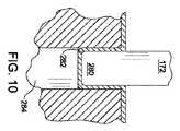
鋸ブレード40がハンドピース42に装着されると、ハンドピースと一体の駆動ピンおよび駆動ロッド50が、協働して、ブレードヘッドの基部124をブレードバーのボス74に対して引っ張るようになっている。従って、鋸ブレード40の作動中、ノッチ138を画定するブレードヘッドの凹面が、ボス74に対して前後に旋回されることになる。図3は、もしブレードヘッドの基部124が当接するボス74の周面が実質的に円筒状でない場合に生じる状態を誇張して示す図である。具体的には、もし不正確な製造方法が実施されると、ボスの表面には、ブレードヘッドの基部124の表面を画定するノッチから近位側に離れるテ―パが付くことがある。図3では、識別番号148で示されるこのテ―パは、説明の目的で誇張されている。具体的には、この場合、ブレードヘッドの基部124がボス74に加える力は、識別番号149によって示される比較的狭い領域にわたって分布されることになる。これは、この領域が、かなり大きい機械的応力およびかなり大きい摩擦熱を受けることを意味している。その結果、これらの2つのエネルギー形態が集中することによって、ボスを形成している材料が損傷する可能性がある。 When the
図4を参照すると、まず、比較的円筒状である旋回ボスをもたらすように、下側プレート54を製造する方法について説明する。具体的には、一連のパンチ成形手順によって、旋回ボス74が下側プレートに形成されることになる。図4では、これらの手順を行う順送り式金属プレス150が、例示されている。プレス150は、静止している下側ダイプレート152を有している。下側ダイプレート152は、露出した上面154を有している。ダイプレート面154は、金属リボン158が載せられる面であり、この金属リボン158から、多数の下側プレート154が連続的に形成されることになる。下側ダイプレートの上面154の上方に、上側パンチプレート160が位置決めされている。上側パンチプレート160から、多数のパンチ162〜174が懸垂され、下側ダイプレート152の方に向けられている。各パンチ162〜174の下方において、下側ダイプレート152は、それぞれ、孔178〜190を有している。パンチと孔の対が位置する各箇所は、プレス150の個々のパンチ成形ステーションとみなされる。 Referring to FIG. 4, a method of manufacturing the
金属プレス150は、プラテン194も備えている。プラテン194は、上側パンチプレート160の下方に延在し、一組のバネ196によって、この上側パンチプレートから懸垂されている。プラテン194には、多数の貫通孔197が形成されている。各パンチ162〜174が、個々のプラテン貫通孔197内に着座している。 The
図示されていないが、上側パンチプレート160、パンチ162〜174、およびプラテン194を下側に位置するダイプレートの上の金属リボン158に押し込む駆動機構も、金属プレス150の一部であることを理解されたい。本発明のいくつかの態様では、駆動機構は、227メートルトン(250英トン)から454メートルトン(500英トン)の間の力で、上側パンチプレート160をダイプレートに押し付けることができる。本発明のいくつかの態様では、駆動機構は、最低90メートルトンの力で、上側パンチプレートをダイプレートに押し付けることが可能である。 Although not shown, it is understood that the drive mechanism that pushes the
また、図示されていないが、移送機構が金属プレス150に取り付けられている。この移送機構は、金属リボン158を段階的なパターンで7つのパンチ成形ステーションの各々間に移動させるものである。従って、プレス150の各作動によって、金属リボンの7つの異なる区域に、パンチ成形手順が行われることになる。各リボン区域に7番目の手順が施されると、旋回ボス74が完全に形成されたと考えることができる。この7番目の手順の後、金属リボン158の各下側プレート形成区域に対して、付加的なプレス加工が施されてもよい。しかし、これらのパンチ成形加工は、ボス74の形成に関連するものではない。 Although not shown, a transfer mechanism is attached to the
本発明のいくつかの好ましい態様では、下側プレート54および上側プレート56を形成する金属リボン158は、420ステンレス鋼または同等の金属から構成されている。このような1つの金属は、スエーデン、サンドヴィーケンのサンドビックABから市販されているサンドビック7C27Mo2帯鋼である。この材料は、重量%で、0.38%の炭素、0.40%の珪素、0.55%のマンガン、最大0.025%の燐、最大0.010%の硫黄、13.5%のクロムを含み、残部が鉄からなる化学組成を有していると理解されたい。金属リボン158の厚みは、0.38mm(0.015インチ)以下である。 In some preferred embodiments of the present invention, the
金属プレスが作動されるたびに、プラテン194は、金属リボン158を押圧するようになっている。プラテン194は、金属リボンをダイプレートの上面154に保持するために、金属リボン158を押し付けるものである。上側パンチプレート160が連続的に下方に移動するにつれて、各パンチ162〜174が、関連するプラテン貫通孔197を貫通することになる。次いで、パンチ成形ステーションにおいて、パンチは、捕捉されて加工可能な状態にある金属リボンの下側に位置する区域を加圧することになる。次いで、各パンチ162〜174は、下側に位置する金属を関連するダイ孔178〜190内に押し込んでいく。この金属リボンの連続的なパンチ成形によって、所望の円筒形状を有する旋回ボス74がもたらされることになる。Each time the metal press is actuated, the
図5は、第1のパンチ成形手順において、いかにパンチ162が旋回ボス74の成形を開始しているかを示している。パンチ162は、残りのパンチ164〜174も同様であるが、大径基部(図示せず)を有している。この基部は、関連するプラテン貫通孔197内におけるパンチの緊密なすべり運動を容易にするように、形作られている。この基部から、小径の細長ステム204が下方に延在している。ステムの下方に、ヘッドが延在している。このヘッドは、ステムよりも細くなっている。パンチ162のこのヘッドは、円筒状の柱脚(pedestal)208を画定するように、形作られている。柱脚208は、関連するステム204よりも小さい直径を有している。柱脚208の下方において、パンチ162は、先端部210を有している。先端部210は、下側に位置する金属リボン158に突き当たるパンチ162の一部である。先端部210は、弾丸状の輪郭を有している。従って、先端部210は、第1の小径曲率半径を有する中心面212を有している。また、先端部210は、中心面212とヘッドの柱脚208の外周との間に延在する周面214を有している。周面214は、中心面212の曲率半径よりも大きい曲率半径を有している。これらの面212,214の曲率半径は、互いに異なっているが、これらの曲面のいずれも、パンチ162の長手方向中心線上に中心を有している。中心面212の曲率中心は、周面214の曲率半径よりもパンチ162の端の近くに位置している。 FIG. 5 shows how the
このパンチ成形手順では、パンチ162のヘッドは、金属リボンの予め平らにされている区域を下側に位置するプレート孔178内に押し込むことになる。従って、この手順の結果として、金属リボンは、識別番号217によって示される弾丸状に突き出した形状のボスを有することになる。 In this punching procedure, the head of the
第1のパンチ成形手順と第2のパンチ成形手順との間で、金属リボン158の一区域、具体的には、弾丸状に突き出した形状のボスが形成されている区域は、第2のパンチ、すなわち、パンチ164が位置しているパンチ成形ステーションに移送されることになる。各パンチ成形手順の後、同様の移送が行われることを理解されたい。これらの付加的な移送手順については、以後、さらに説明しない。 Between the first punch molding procedure and the second punch molding procedure, one area of the
第2のパンチ164〜第7パンチ174は、ボス74を、そのボスが所望の円筒形状を有するように、再成形するものである。図6に最もよく示されるように、第2のパンチ164は、ステム217を有している。このステム217から、ステム217の直径よりも小さい直径を有する円筒状の柱脚218が延在している。柱脚は、丸形の先端部220を有するように、形作られている。第2のパンチ164の柱脚218は、第1のパンチ162の柱脚208よりも大きい直径を有している。先端部220は、中心面222を有するように、形作られている。中心面222は、円形であり、第1の曲率半径を有している。中心面222と柱脚214との間において、先端部220は、周面224を有している。周面224は、中心区域222の曲率半径よりも大きい曲率半径を有している。従って、第2のパンチの先端部220を通るどのような横方向線に沿っても、中心面222は、パンチ164の長軸に沿った点を中心とする1つの曲率半径を有し、先端部220の両端部において、周面224は、長軸の両側に位置する2つの曲率半径を有している。 The
また、基部202の自由端から先端部の中心区域222の対向端までの第2のパンチ164の全長は、第1のパンチ162の対応する全長よりも短いことを理解されたい。図4では、これらの長さの差は、説明の目的で誇張して示されている。従って、図6に示されるように、第2のパンチ成形手順の結果として、ボスの端部は、第1の手順における形状と比較して、丸みの少ない端とその直上の湾曲が少なくてより角度の付いた移行区域とを有する形状とに再成形されることになる。 It should also be understood that the overall length of the
図7は、第3のパンチ、すなわち、パンチ166およびこのパンチによる変形の結果として得られたボスの形状を示している。具体的には、第3のパンチ166は、略円筒状の先端部232を有している。先端部232の直径は、第2のパンチ164の柱脚218の直径よりも大きくなっている。先端部232は、平らな外面234を有している。外面234と円筒状の側壁との間において、先端部232は、湾曲コーナ236を有している。コーナ236の曲率半径は、第2のパンチの先端部の周面224の曲率半径よりも小さくなっている。 FIG. 7 shows the shape of the third punch, ie, the
第3のパンチ166の全長は、第2のパンチ164の全長よりも短くなっている。パンチ166は、残りのパンチ168〜174も同様であるが、それらの基部と金属成形ヘッドとの間に中間ステム区域を有しないように、形作られている。 The overall length of the
その結果、第3のパンチ成形手順の結果として、成形中のボスの端は、連続的により平面的な形状に再成形されることになる。また、ボスの上部に隣接するボスの環状区域(図7では、上下逆に示されている)は、より円筒形状に加圧されることになる。さらに、ボスを形成する材料が外方に変形する結果として、ボスの全長は、その元の形状に対して、減少し始めている。 As a result, as a result of the third punch molding procedure, the ends of the bosses being molded are continuously reshaped into a more planar shape. In addition, the annular area of the boss adjacent to the top of the boss (shown upside down in FIG. 7) is more pressurized in a cylindrical shape. Furthermore, as a result of the outward deformation of the material forming the boss, the overall length of the boss begins to decrease with respect to its original shape.
図8に示される第4のパンチ168は、第3のパンチ166の先端部232と同一の基本的な形状の先端部238を有している。先端部238は、先端部232と同一の外径を有している。また、先端部238は、平らな外面240を有している。外面240と円筒状の周面との間において、先端部238は、湾曲コーナ242を有している。コーナ242は、第3のパンチ166のコーナ236の曲率半径よりも小さい曲率半径を有している。第4のパンチ168は、第3のパンチ166の全長よりもわずかに短い全長を有している。 The
ダイプレート孔184、すなわち、成形中に第4のパンチ168がボスを加圧する孔は、その全体が開通していない。孔184には、残りの孔186,188,190も同様であるが、プラグ248が装着されている。図4に示されるように、プラグ248は、ダイプレート152の下方に位置する基部プレート250上に着座している。実際には、プラグ248は、基部プレート上に置かれたシム252(1つのみが図示されている)上に置かれることになる。シム252は、ダイプレートの上面154に対するプラグのヘッドの相対的な位置を調節するために、選択的に取り外され、かつ置き換えられるようになっている。プラグを孔186,188,190内に位置決めするために、シムが同様に用いられることを理解されたい。 The
プラグ248は、成形中のボスが孔内に最初に着座されるとき、ボスの先端がプラグの露出面に置かれるように、孔184内に位置決めされている。上側パンチプレート160が下降するとき、プラテン194が、部分的に成形されたボスをプラグ248に対して保持している。次いで、第4のパンチ168が、ボスを形成する金属の内面を加圧することになる。その結果、ボスの端部は、プラグ248の上部とパンチの先端部238との間に挟み込まれることになる。この操作の結果として、ボスの上部が平面形状になる程度が大きくなる。また、ボスの環状側壁とその上面との間の移行部が直角の輪郭を呈する程度も大きくなる。
第5のパンチ170は、第4のパンチの先端部238と極めて類似している先端部252を有している。先端部の外径は、同一である。これらの先端部間の差異は、先端部252が、先端部238のコーナの曲率半径よりも小さい曲率半径を有するコーナ254を有することである(すなわち、移行部により大きな角度が付けられている)。第5のパンチ170は、第4のパンチ168よりも短くなっている。プラグ256が、ダイプレスの孔186、すなわち、パンチ170が挿入されている孔内に着座している。プラグ256は、その先端部、すなわち、孔186内の端部が、プラグ248の先端部よりもダイプレートの上面に近くなるように、孔186内に位置決めされている。 The
従って、このパンチ成形手順では、パンチの先端部252は、成形中のボスをプラグ256に対して加圧することになる。この操作によって、ボスをさらに平坦にし、ボスが円筒形状を有する程度を増大させることになる。 Accordingly, in this punch molding procedure, the
第6および第7のパンチ成形手順は、第4および第5のパンチ成形手順と同様である。しかし、第6のパンチ172は、第5のパンチの先端部252よりもわずかに小さい直径を有する先端部280を有している。第6のパンチの先端部は、第4のパンチ170のコーナ面254の曲率半径よりも小さい曲率半径を有するコーナ面282を有している。第6のパンチ172の全長は、第5のパンチ170の全長よりも短くなっている。 The sixth and seventh punch forming procedures are the same as the fourth and fifth punch forming procedures. However, the
ダイプレート孔188、すなわち、第6のパンチ172が延在している孔内に、プラグ284が着座している。シム252が、孔の先端がプラグの先端部よりもダイプレートの上面154に近くなるように、プラグを孔284内に保持している。 A
第7のパンチ成形手順は、旋回ボス74を成形する最終プロセスである。第7のパンチ174は、第5のパンチの先端部252の直径と等しい直径を有する先端部290を有している。パンチの先端部290は、第6のパンチのコーナ面282の曲率半径と等しい曲率半径を有するコーナ292を有している。第7のパンチ174は、第6のパンチ172よりもわずかに短くなっている。 The seventh punch forming procedure is the final process of forming the
第7のパンチ174が延在しているダイプレート孔190内には、プラグ294が形成されている。プラグ294は、その先端部がプラグ284の先端部と比較してダイプレートの上面154に近くなるように、孔190内に位置決めされている。 A
第7のパンチ成形手順の結果として、旋回ボス74は、下側プレート54を形成する金属の残りからすぐにほぼ直角に立ち上がった外壁を有することになる。旋回ボスの外周壁は、本質的に円筒状である。図11では上下逆に示されているボスの上面は、本質的に平坦である。 As a result of the seventh punching procedure, the pivoting
このプロセスでは、ボスを形成する金属の表面応力が最小限に抑えられている。この応力の低減は、ブレード基部が旋回ボスに付勢されて、このボスを中心として繰り返し旋回されるとき、これらの運動の力がボスを形成する金属を損傷させる可能性が小さいことを意味している。さらに、旋回ボスがブレード基部に対して円筒面を有しているので、ボスに対するブレード基部の力は、比較的広い領域にわたって分布されることになる。旋回によって生じた熱も、同じように、分布されることになる。旋回ボス74内へのこの機械的エネルギーおよび熱的エネルギーの拡散は、同じように、ボスを形成する材料が損傷する傾向を最小限に抑えるのに役立つことになる。 In this process, the surface stress of the metal forming the boss is minimized. This reduction in stress means that when the blade base is urged against the swivel boss and repeatedly swiveled around this boss, the forces of these movements are less likely to damage the metal that forms the boss. ing. Furthermore, since the pivoting boss has a cylindrical surface with respect to the blade base, the force of the blade base against the boss will be distributed over a relatively wide area. The heat generated by the swirling will be distributed in the same way. This diffusion of mechanical and thermal energy into the
パンチ成形手順の各々において、金属リボン158から下側プレート54を形成するのに必要な他のプロセスが、行われてもよいことを理解されたい。このような他のプロセスの例として、リボンからプレートの全体を成形するプロセス、開口62,68,76,84を形成するプロセス、およびタブ78を形成するプロセスが挙げられる。別の1つまたは複数の手順(図示せず)において、個々に形成された下側プレート54が、金属リボンの先端から切断されることになる。 It should be understood that other processes necessary to form the
鋸ブレード40を形成するプレートおよび他の部品が形成された時点で、これらの部品が一緒に組み立てられることになる。次いで、一連のレーザ溶接手順を用いて、下側プレート54および上側プレート56を一緒に固定することになる。図12および図13は、この溶接が行われる順序を示している。図12に示される第1の手順“1”では、下側プレート54を貫通する溶込み溶接部を用いて、上側プレートのガセット106の隠れている内面を下側プレート54に溶接するようになっている。この溶接では、一連の重ね合わせスポット溶接部が形成されることになる。各溶接部は、略0.97mm(0.038インチ)の直径を有している。個々の溶接部は、略0.33mm(0.013インチ)だけ互いに離間している。 Once the plate and other parts forming the
図12に示される次の溶接手順“2”では、一連の重ね合わせ溶込みスポット溶接部を用いて、開口102の前方のガセット98の部分を下側プレートに溶接するようになっている。この溶接は、開口102の前端に近い位置から始まり、ブレードバーの遠位端に向かって進められることになる。この手順では、ガセットの全体が、下側プレートに溶接されるようにはなっていない。代わって、手順“3”において、下側プレート54は、ガセット98の遠位端から始まる溶接部によって、ガセット98に溶接されるようになっている。この手順“3”によって形成される溶接部は、手順“2”によって形成された溶接部の遠位端の手前で停止している。 In the next welding procedure “2” shown in FIG. 12, a portion of the
手順“2”,“3”におけるスポット溶接プロセスでは、溶接部は、手順“1”における溶接部の直径と同一の直径を有している。しかし、手順“2”,“3”における溶接部は、略0.20mm(0.008インチ)の間隔を隔てて、より密集して配列されるようになっている。 In the spot welding process in the procedures “2” and “3”, the weld has the same diameter as the weld in the procedure “1”. However, the welds in the procedures “2” and “3” are arranged more densely with an interval of approximately 0.20 mm (0.008 inch).
手順“4”では、溶込み溶接を用いて、下側プレート54とガセット98の広幅近位端部との間に略U字状の溶接部を形成するようになっている。 In the procedure “4”, a welding portion having a substantially U shape is formed between the
手順“5”では、下側プレート54を旋回ボス74の上部の周囲に溶接するように、円形溶接部が形成されるようになっている。ここでも、溶接は、溶込み溶接プロセスによって行われている。この溶接プロセスでは、略0.84mm(0.033インチ)の直径を有する個々の溶接部が形成されている。円形溶接部をもたらすために、略40個のスポット溶接部が、360°の円に沿って形成されている。 In the procedure “5”, a circular weld is formed so that the
溶接部がブレードバー44の中心に沿って形成された時点で、上側ブレードのリップ88が下側プレート54の外縁に隣接している界面に沿って、溶接部が形成されることになる。図13に示される手順“6”は、これらの溶接部の内の第1の溶接部を表している。この溶接部は、図13において、ブレードバーの片側の最遠位タブ78の遠位側の点から始まり、開口84の1つの側方の点、すなわち、点290の前方まで延在している。手順“7”では、ブレードバー44の反対側に、同一の溶接部が形成されることになる。 When the weld is formed along the center of the blade bar 44, the weld is formed along the interface where the upper blade lip 88 is adjacent to the outer edge of the
手順“6”,“7”が実施された時点で、2つの付加的な溶接部が、ブレードバー44の片側に沿って、具体的には、手順“6”において溶接部が形成された側に沿って形成されることになる。手順“8”では、2つのタブ78間において、上側プレートのリップと下側プレートとの間の界面に沿って、溶接部が形成されるようになっている。手順“9”では、最近位タブ78から近位側に延在する線に沿って、溶接部が形成されるようになっている。 When Steps “6” and “7” are performed, two additional welds follow along one side of the blade bar 44, specifically the side where the weld was formed in Step “6”. It will be formed along. In procedure “8”, a weld is formed between the two
次いで、手順“10”では、短い溶接部が、下側プレートの基部58のテーパの付いた外縁に沿って、2つのプレート間に形成されるようになっている。手順“11”では、手順“10”における溶接部の近位端から後方に向かって短距離にわたり、基部に沿って形成されるようになっている。手順“11”では、溶接部は、下側プレートの基部58の側面と近位端との間の湾曲部に沿って形成されることになる。手順“8”,“9”,“10”,“11”の各々において、溶接は、ブレードバー44の近位端に向かって後方に移動する経路に沿って、行われることになる。 Then, in step “10”, a short weld is formed between the two plates along the tapered outer edge of the
図13に示される一連の手順“12”,“13”,“14”,“15”では、溶接部が、ブレードバーの反対側に形成されるようになっている。手順“12”,“13”,“14”,“15”における溶接部は、それぞれ、手順“8”,“9”,“10”,“11”の溶接部に対応している。 In the series of procedures “12”, “13”, “14”, and “15” shown in FIG. 13, the welded portion is formed on the opposite side of the blade bar. The welds in the procedures “12”, “13”, “14”, and “15” correspond to the welds in the procedures “8”, “9”, “10”, and “11”, respectively.
手順“8”〜“15”では、重ね合わせスポット溶接部の個々のスポットは、略0.71mm(0.028インチ)の直径を有している。溶接部の中心は、略0.32mm(0.0125インチ)だけ互いに離間している。 In procedures “8” to “15”, the individual spots of the overlap spot weld have a diameter of approximately 0.71 mm (0.028 inches). The centers of the welds are separated from each other by approximately 0.32 mm (0.0125 inch).
手順“16”では、溶接部は、手順“7”によって生成された溶接部の前方に形成されるようになっている。手順“16”では、溶接部は、プレート54,56の遠位端に延在するように、形成されている。次いで、手順“17”では、溶接部は、プレート54,56の反対側に形成されるようになっている。従って、手順“17”における溶接部は、手順“6”において生成された溶接部の前方に延在している。手順“16”,“17”において形成されたスポット溶接部は、手順“8”〜“15”において生成されたスポット溶接部と同一の直径を有している。しかし、これらの溶接部は、より密集して重ねられている。手順“16”,“17”における溶接部間の中心点間隔は、略0.061mm(0.0024インチ)である。 In the procedure “16”, the welded portion is formed in front of the welded portion generated by the procedure “7”. In procedure “16”, the weld is formed to extend to the distal ends of the
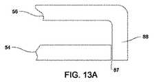
手順“6”〜“17”における溶接部が所望の強度を有するために、下側バー(下側プレート)54の外側縁は、上側バー(上側プレート)56のリップ88の隣接する内面に対して密接に配置されねばならない。これらの面間の間隙87(図13A)は、0.025mm(0.001インチ)以下であるべきである。理想的には、これらの面は、互いに当接させるべきである。 In order for the welds in procedures “6” to “17” to have the desired strength, the outer edge of the lower bar (lower plate) 54 is against the adjacent inner surface of the lip 88 of the upper bar (upper plate) 56. Must be closely arranged. The
ブレード40を旋回ボスが所望の幾何学的形状を有するように組み立てるために、他の手段が用いられてもよいことを理解されたい。 It should be understood that other means may be used to assemble the
例えば、旋回ボスは、ブレードバーを形成する上側プレートおよび下側プレートのいずれかとは別の部品から形成されてもよい。図14Aは、円板状のヘッド302を有する旋回シャフト301を示している。ヘッド302の両面から、2つの円筒状の耳部304が外方に延在している。これらの耳部は、ヘッド302の直径よりも小さい共通の直径を有している。図14Bに示されるように、本発明のこの態様のブレードが組み立てられると、ボスの耳部304は、下側プレート54および上側プレート56に形成された別々の孔308,310にそれぞれ着座することになる。耳部は、隣接しているプレートに溶接されている。ピンヘッド302は、ブレードヘッド46が旋回するときに旋回中心となる円筒状の部材として機能することになる。 For example, the swivel boss may be formed from a part different from any of the upper plate and the lower plate forming the blade bar. FIG. 14A shows a turning
旋回シャフト301の図示されない態様では、シャフトは、単一の耳部が延在する円筒状のヘッドを有するようになっている。この耳部は、下側プレート54または上側プレート56の1つの貫通孔内に着座することになる。ヘッドの他の側の平坦な面は、上側プレートまたは下側プレートの他の1つの隣接している面に溶込み溶接されるとよい。 In a not shown embodiment of the
代替的に、図15Aに示されるように、旋回シャフト312は、スピンドル形状を有していてもよい。シャフト312は、2つの大径円板状の耳部314を有している。小径円筒状のヘッド316が、耳部314間に延在し、耳部314を接続するようになっている。図15Bに示されるように、シャフト312を有するブレードが組み立てられると、ヘッド316が、ブレードヘッドが旋回するときに旋回中心となる円筒状の部材として機能することになる。 Alternatively, as shown in FIG. 15A, the
本発明のいくつかの態様では、ブレードヘッドが旋回するときに旋回中心となるシャフトは、一定直径の円筒状のピン(図示されず)であってもよい。ピンの両端が、ブレードバーを形成する2つのプレートの開口に一列に並んで取り付けられることになる。 In some aspects of the present invention, the shaft that is the pivot center when the blade head pivots may be a cylindrical pin (not shown) having a constant diameter. Both ends of the pin will be attached in line to the openings in the two plates forming the blade bar.
本発明のブレードの代替的形態では、図16Aおよび図16Bに示されるように、ブレードバー44aには、側方開口330が形成されている。 In an alternative form of the blade of the present invention, as shown in FIGS. 16A and 16B, a
本発明のこの態様では、ブレードは、タブが形成されている基部124aを有するブレードヘッド46aを有している。基部の遠位区域128aの側縁から横方向(外方)に延在するタブ332が、図17に示されている。本発明の例示された態様では、タブ332の外面は、凹状輪郭を有している。この輪郭は、例示にすぎず、制限するものではないことを理解されたい。本発明のいくつかの態様では、これらのタブは、三角形の輪郭を有している。すなわち、各タブは、基部の遠位区域から延在する外向きのテ―パを有する面を有している。その結果、最も広い最近位位置において、タブは、直角または直角に近い角度で遠位区域と交わる縁を有することになる。本発明のさらに他の態様では、各タブ332の外縁は、直線状の縁である。図示されていないが、同様のタブが、基部の近位区域から外方に延在していることを理解されたい。 In this aspect of the invention, the blade has a blade head 46a having a
これらのタブは、ブレードヘッド46aがブレードバー44の片側に旋回したとき、隣接する開口330から外に突出するように、位置決めされている。従って、これらのタブは、ブレードバー内に捕捉された破片をブレードバーの外に押し出す鋤として機能することになる。この破片の排出によって、破片がブレードバーを詰まらせてブレードの作動に悪影響を与える傾向が、最小限に抑えられることになる。 These tabs are positioned so that when the blade head 46 a pivots to one side of the blade bar 44, it protrudes out of the
また、図17は、円弧形状を有するブレードヘッドクラウン48aも示している。すなわち、このクラウンの両側縁340は、共通の中心点から突出する互いに離間した2つの半径線上にある。ブレードヘッドのクラウン48aは、クラウンの両近位端で、外方に突出するフィンガー342を有すべく、さらに形成されている。各フィンガー342は、関連する側縁から外方に延在している。各フィンガーは、略J字状の形状を有し、フィンガーの鉤状端がブレード歯の遠位端が位置する半径方向前方に延在するように、配向されている。 FIG. 17 also shows a
ブレードヘッドクラウン48aを有するブレードが作動されると、フィンガー342は、ブレード歯によって生じた切口内に捕捉された破片をクラウン48aの移動経路から外に押し出すことになる。この破片の排出によって、破片が切断効率を低減させる程度および破片が後方に移動してブレードバー内に捕捉され得る程度が、軽減されることになる。 When the blade having the
図18は、本発明のブレードアセンブリの一部の代替的な構造を示している。具体的には、図18は、いかに平坦な駆動足350がブレードアセンブリの駆動ロッド50aの近位端に連結されるかを示している。本発明のこの態様では、フィンガー142(図2)と同じように重なっているフィンガー352が、各駆動ロッド50aから近位側(後方)に延在している。駆動足350は、互いに向き合った外方に延在するタブ354を有している。各タブ354は、1対の重なっている駆動ロッドフィンガー352によって画定された長孔内に旋回可能に装着されている。 FIG. 18 illustrates an alternative construction of a portion of the blade assembly of the present invention. Specifically, FIG. 18 shows how a
足350は、名目上ブレードアセンブリの長軸に沿って配向されている互いに向き合った2つのタブ356も有している。各タブ356は、開口358を有している。本発明のこのブレードアセンブリは、名目上ハンドピースの長軸と一直線に並んでいる2つの駆動ピンによって、駆動ヘッドを有するハンドピースに取り付けるためのものである。駆動ピンが振動すると、足350が同様の運動を受けることになる。この運動が、駆動ロッド50aを前後に往復運動させ、これによって、所望のブレードヘッドの旋回を生じさせることになる。 The
代替的に、足350には、非円形輪郭の中心孔が形成されている。本発明のこの態様によるブレードは、単一の駆動ピンによって、ハンドピースに取り付けられるようになっている。駆動ピンは、ブレード足350の相補的な孔に緊密にすべり嵌合されることが可能になる断面形状を有している。ハンドピースが作動されると、駆動ピンが振動することになる。この運動によって、足350に同様の運動が生じることになる。足350は、この振動を駆動ロッド50aに伝達し、これによって、駆動ロッドを往復運動させることになる。 Alternatively, the
このように、前述の説明は、本発明によるブレードの特別の特徴および製造方法に向けられていると理解されたい。しかし、本発明は、前述の構成から変更されてもよい。 Thus, it should be understood that the foregoing description is directed to specific features and methods of manufacture of the blade according to the present invention. However, the present invention may be modified from the above configuration.
例えば、パンチ成形によって旋回ボスを形成する方法およびバーを形成する下側プレートおよび上側プレートをレーザ溶接する方法は、本発明の全ての態様において実施される必要がない。これらの方法は、適切であれば、単独で実施されてもよい。 For example, the method of forming the pivot bosses by punching and the method of laser welding the lower and upper plates forming the bar need not be implemented in all aspects of the invention. These methods may be performed alone if appropriate.
本発明によるパンチ成形によって旋回ボスを形成する方法では、旋回ボスをそのボスが所望の幾何学的形状を有するように形成するために、および旋回ボスを形成する材料が所望の応力のない表面仕上げを有することを確実にするために、多かれ少なかれ、複数の手順が必要とされることになる。 In a method of forming a swivel boss by punch molding according to the present invention, the swivel boss is formed so that the boss has a desired geometric shape, and the material from which the swivel boss is formed has a desired stress-free surface finish. More or less multiple procedures will be required to ensure that
代替的な手段を用いて、旋回ボスを形成してもよい。例えば、ブランク加工材を選択エッチングすることによって、旋回ボスと共に枢動ボスと一体のプレートの残りを形成することも可能である。このエッチングの結果として、ブレードプレートの他の特徴とまではいかなくても、少なくとも旋回ボスを所望の形状にすることができる。また、本発明のいくつかの態様では、旋回ボスの外壁は、必ずしも完全な円状の断面輪郭を有している必要はない。 Alternative means may be used to form the pivot boss. For example, it is also possible to form the remainder of the plate integral with the pivot boss with the pivot boss by selectively etching the blank workpiece. As a result of this etching, at least the swivel boss can be shaped as desired without going to other features of the blade plate. Also, in some aspects of the invention, the outer wall of the pivot boss need not necessarily have a complete circular cross-sectional profile.
本発明による下側プレートおよび上側プレートのレーザ溶接において、代替的な溶接順序が実施されてもよい。 In laser welding of the lower and upper plates according to the present invention, an alternative welding sequence may be implemented.
さらに、本発明のいくつかの態様では、所望の溶接部を形成するのに、レーザ溶接以外のプロセスが行われてもよい。すなわち、本発明のいくつかの態様では、ガセットの中心溶接部を形成ために、および/または上側プレート54および下側プレート56の両側面を溶接するために、アーク溶接、分割電子ビーム溶接、または抵抗溶接が用いられてもよい。 Further, in some aspects of the invention, processes other than laser welding may be performed to form the desired weld. That is, in some aspects of the invention, arc welding, split electron beam welding, or to form the center weld of the gusset and / or to weld both sides of the
従って、添付の請求項の目的は、本発明の真の精神および範囲内に含まれる全てのこのような変更および修正を包含することにある。 Accordingly, it is the object of the appended claims to cover all such changes and modifications as fall within the true spirit and scope of the invention.
Claims (15)
Translated fromJapanese互いに向き合ったプレート(54,56)から形成されたブレードバー(44)を設けるステップであって、前記ブレードバー(44)は、遠位端隙間、および前記プレート間に延在するボス(74)を有する、ステップと、
ブレードヘッド(46)を前記ブレードバーの前記隙間の遠位端内に位置決めするステップであって、前記ブレードヘッドは、前記ボスを中心として旋回するように前記ボスに対して配置された基部、および前記ブレードバーの外側に位置するクラウン(48)を有し、前記クラウンには歯(49)が形成されている、ステップと、
を含み、
前記ボス(74)は、前記ボスが少なくとも部分的に円形である外壁および前記外壁と実質的に直交する上面を有すべく、前記ボスを画定して、前記プレートの1つ(54)を成形することにより形成されることを特徴とする方法。In a method of assembling a surgical sagittal saw blade assembly (40) having an oscillating tip,
Providing a blade bar (44) formed from opposed plates (54, 56), the blade bar (44) having a distal end gap and a boss (74) extending between the plates; Having a step;
Positioning a blade head (46) within the distal end of the gap of the blade bar, the blade head being disposed relative to the boss so as to pivot about the boss; and Having a crown (48) located outside the blade bar, the crown being formed with teeth (49);
Including
The boss (74) defines the boss to form one of the plates (54) so that the boss has an outer wall that is at least partially circular and an upper surface substantially orthogonal to the outer wall. A method characterized by being formed by:
ブレードバーを形成するために、互いに向き合ったプレート(54,56)を一緒に溶接するステップであって、前記プレートは、長手方向に延在する側面を有し、前記ブレードバーは、遠位端隙間、および前記遠位端隙間の内方に位置する旋回ボス(74)を有する、ステップと、
ブレードヘッド(46)を前記ブレードバーの前記隙間の遠位端内に位置決めするステップであって、前記ブレードヘッドは、前記ボスを中心として旋回するように前記ボスに対して配置された基部、および前記ブレードバーの外側に位置するクラウン(48)を有し、前記クラウンには歯(49)が形成されている、ステップと、
を含み、
前記ブレードバーを形成するために、前記プレートを一緒に溶接するプロセスは、
前記プレート間に少なくとも1つの中心溶接部(1,2,3,4,5)を形成するステップであって、前記中心溶接部は、前記プレートの互いに向き合った側面の内方に位置している、ステップと、
前記少なくとも1つの中心溶接部が形成された後、前記プレートの第1の側の第1の区域において、前記プレートの互いに隣接する面を一緒に溶接し(6)、前記プレートの第2の側の第1の区域において、前記プレートの互いに隣接する面を一緒に溶接し(7)、前記プレートの前記第1の側の第2の区域において、前記プレートの互いに隣接する面を一緒に溶接し(8)、および前記プレートの前記第2の側の第2の区域において、前記プレートの互いに隣接する面を一緒に溶接する(12)ようにして、前記プレートを一緒に溶接するステップと、
によって行われることを特徴とする方法。In a method of assembling a surgical sagittal saw blade assembly (40) having an oscillating tip,
Welding the plates (54, 56) facing each other together to form a blade bar, the plate having longitudinally extending sides, the blade bar having a distal end Having a gap and a pivoting boss (74) located inside the distal end gap;
Positioning a blade head (46) within a distal end of the gap of the blade bar, the blade head being disposed relative to the boss so as to pivot about the boss; and Having a crown (48) located outside the blade bar, the crown being formed with teeth (49);
Including
The process of welding the plates together to form the blade bar comprises:
Forming at least one central weld (1, 2, 3, 4, 5) between the plates, the central weld being located inward of the mutually facing sides of the plate , Steps and
After the at least one central weld is formed, in the first zone on the first side of the plate, the adjacent faces of the plate are welded together (6) and the second side of the plate Welding the adjacent faces of the plate together in a first zone of the plate (7) and welding the adjacent faces of the plate together in a second zone of the first side of the plate. (8) and welding the plates together such that, in a second zone on the second side of the plate, the adjacent faces of the plate are welded together (12);
A method characterized by being performed by:
前記プレート間に中心溶接部を形成する前記ステップにおいて、前記ガセットは、前記プレートの内の第2のプレートの隣接する内面に溶接されることを特徴とする、請求項8あるいは9に記載の振動先端を有する外科用鋸ブレードを組み立てる方法。At least one inwardly directed gusset (98, 106) is formed in a first of the plates.
10. Vibration according to claim 8 or 9, characterized in that in the step of forming a central weld between the plates, the gusset is welded to an adjacent inner surface of a second plate of the plates. A method of assembling a surgical saw blade having a tip.
前記プレートを一緒に溶接する前記ステップにおいて、溶接部が、前記第1のプレートの前記リップ(88)の前記側面と前記プレートの内の前記第2のプレート(54)の前記側縁面との間に形成されることを特徴とする、請求項8,9あるいは10に記載の振動先端を有する外科用鋸ブレードを組み立てる方法。A first plate (56) of the plates has lips (88) extending along the outer peripheries of both sides of the plate, the plates being within the plate when placed together. A side edge surface of the second plate (54) is formed in cooperation so as to be adjacent to a side surface of the lip of the first plate;
In the step of welding the plates together, a weld is formed between the side surface of the lip (88) of the first plate and the side edge surface of the second plate (54) of the plate. 11. A method for assembling a surgical saw blade having a vibrating tip according to claim 8, 9 or 10, characterized in that it is formed between.
前記プレートを一緒に中心溶接する前記ステップにおいて、前記旋回ボスは、前記プレートの内の第2のプレート(56)に溶接されることを特徴とする、請求項8,9,10あるいは11に記載の外科用鋸ブレードを組み立てる方法。The swivel boss (74) is a portion formed integrally with the first plate (54) of the plate before bringing the plates (54, 56) together,
12. The swivel boss is welded to a second plate (56) of the plates in the step of center welding the plates together. To assemble a surgical saw blade.
Applications Claiming Priority (2)
| Application Number | Priority Date | Filing Date | Title |
|---|---|---|---|
| US83905106P | 2006-08-21 | 2006-08-21 | |
| PCT/US2007/076321WO2008024717A2 (en) | 2006-08-21 | 2007-08-20 | Method for manufacturing a oscillating tip surgical saw blade |
Related Child Applications (1)
| Application Number | Title | Priority Date | Filing Date |
|---|---|---|---|
| JP2012254874ADivisionJP2013056194A (en) | 2006-08-21 | 2012-11-21 | Method for manufacturing oscillating tip surgical saw blade by selectively welding plate forming blade bar |
Publications (2)
| Publication Number | Publication Date |
|---|---|
| JP2010501275Atrue JP2010501275A (en) | 2010-01-21 |
| JP2010501275A5 JP2010501275A5 (en) | 2010-10-07 |
Family
ID=39031070
Family Applications (2)
| Application Number | Title | Priority Date | Filing Date |
|---|---|---|---|
| JP2009525717APendingJP2010501275A (en) | 2006-08-21 | 2007-08-20 | Method of manufacturing an oscillating tip surgical saw blade |
| JP2012254874APendingJP2013056194A (en) | 2006-08-21 | 2012-11-21 | Method for manufacturing oscillating tip surgical saw blade by selectively welding plate forming blade bar |
Family Applications After (1)
| Application Number | Title | Priority Date | Filing Date |
|---|---|---|---|
| JP2012254874APendingJP2013056194A (en) | 2006-08-21 | 2012-11-21 | Method for manufacturing oscillating tip surgical saw blade by selectively welding plate forming blade bar |
Country Status (9)
| Country | Link |
|---|---|
| US (2) | US8323285B2 (en) |
| EP (1) | EP2053978B1 (en) |
| JP (2) | JP2010501275A (en) |
| KR (1) | KR101432842B1 (en) |
| CN (1) | CN101616632A (en) |
| AU (1) | AU2007286798B2 (en) |
| CA (1) | CA2661225A1 (en) |
| DK (1) | DK2053978T3 (en) |
| WO (1) | WO2008024717A2 (en) |
Cited By (2)
| Publication number | Priority date | Publication date | Assignee | Title |
|---|---|---|---|---|
| JP2013132691A (en)* | 2011-12-22 | 2013-07-08 | Feintool Intellectual Property Ag | Method and device for producing metallic bipolar plate |
| JP2018515234A (en)* | 2015-05-12 | 2018-06-14 | ストライカー・ユーロピアン・ホールディングス・I,リミテッド・ライアビリティ・カンパニー | Surgical sagittal blade cartridge with reinforced guide bar |
Families Citing this family (23)
| Publication number | Priority date | Publication date | Assignee | Title |
|---|---|---|---|---|
| US7497860B2 (en) | 2004-07-09 | 2009-03-03 | Stryker Corporation | Surgical sagittal saw including a handpiece and a removable blade assembly, the blade assembly including a guide bar, a blade head capable of oscillatory movement and a drive rod for actuating the blade head |
| US7704254B2 (en) | 2005-09-10 | 2010-04-27 | Stryker Corporation | Surgical sagittal saw with indexing head and toolless blade coupling assembly for actuating an oscillating tip saw blade |
| JP2010501275A (en)* | 2006-08-21 | 2010-01-21 | ストライカー・アイルランド・リミテッド | Method of manufacturing an oscillating tip surgical saw blade |
| DE102008063239A1 (en)* | 2008-12-16 | 2010-06-17 | Aesculap Ag | Surgical saw blade protection device for knee endoprosthetic application, has insertion opening for opening lateral side and/or distal-side of retaining area for insertion of toothless saw blade section of saw blade |
| DE102008062880A1 (en)* | 2008-12-16 | 2010-06-17 | Aesculap Ag | Surgical sawing device for implantation of e.g. artificial hip joint prosthesis, has saw blade pivotable around oscillation axis that runs through central area formed between distal and proximal ends of saw blade |
| US20110046627A1 (en)* | 2009-08-21 | 2011-02-24 | Chong Chol Kim | Reciprocating Surgical Saws With Blade Assemblies |
| US8499674B2 (en) | 2010-09-22 | 2013-08-06 | Robert Bosch Gmbh | Yoke accessory tool for an oscillating tool |
| JP2014527859A (en)* | 2011-07-27 | 2014-10-23 | ストライカー・アイルランド・リミテッド | A blade cartridge having a surgical sagittal saw body and a reinforcing rib formed integrally with the blade bar |
| EP2782696A1 (en)* | 2011-11-22 | 2014-10-01 | Robert Bosch GmbH | Yoke accessory tool for an oscillating tool |
| DE102012208365A1 (en)* | 2011-12-20 | 2013-06-20 | Robert Bosch Gmbh | Rotary Oscillating Saw Blade for a machine tool |
| US8858559B2 (en) | 2012-02-06 | 2014-10-14 | Medtronic Ps Medical, Inc. | Saw blade stability and collet system mechanism |
| US8936597B2 (en) | 2012-02-06 | 2015-01-20 | Medtronic Ps Medical, Inc. | Deflectable finger connection feature on surgical saw blade |
| US10342553B2 (en) | 2015-01-21 | 2019-07-09 | Stryker European Holdings I, Llc | Surgical sagittal saw and complementary blade with features that fixedly hold the blade static to the saw |
| US10716578B2 (en)* | 2016-03-05 | 2020-07-21 | Stryker European Holdings I, Llc | Surgical blade cartridge with a guide bar having features to control the depth of the cut formed with the cartridge |
| US10456142B2 (en) | 2016-06-03 | 2019-10-29 | Mako Surgical Corp. | Surgical saw and saw blade for use therewith |
| US10687824B2 (en)* | 2017-07-21 | 2020-06-23 | Stryker European Holdings I, Llc | Surgical saw and saw blade for use therewith |
| US10906108B2 (en)* | 2018-04-24 | 2021-02-02 | Robert Bosch Tool Corporation | Blade accessory with guide |
| US11974785B2 (en) | 2020-10-16 | 2024-05-07 | Globus Medical, Inc | Band clamp implants |
| US11771475B2 (en) | 2020-10-07 | 2023-10-03 | Globus Medical, Inc. | Systems and methods for surgical procedures using band clamp implants and tensioning instruments |
| WO2022133340A2 (en)* | 2020-12-18 | 2022-06-23 | Stryker European Operations Limited | Surgical sagittal blade cartridge |
| USD1084335S1 (en) | 2022-06-22 | 2025-07-15 | Stryker European Operations Limited | Surgical blade cartridge |
| USD1084334S1 (en) | 2022-06-22 | 2025-07-15 | Stryker European Operations Limited | Surgical blade cartridge |
| US20240237992A1 (en)* | 2023-01-12 | 2024-07-18 | Arthrex, Inc | Quick connect saw attachment for surgical instruments |
Citations (1)
| Publication number | Priority date | Publication date | Assignee | Title |
|---|---|---|---|---|
| WO2006017066A2 (en)* | 2004-07-09 | 2006-02-16 | Stryker Corporation | Surgical sagittal saw and method of using same |
Family Cites Families (11)
| Publication number | Priority date | Publication date | Assignee | Title |
|---|---|---|---|---|
| DE478354C (en)* | 1927-03-15 | 1929-06-24 | Sanimed Akt Ges | Surgical bone saw with electric drive |
| US5122142A (en)* | 1990-09-13 | 1992-06-16 | Hall Surgical Division Of Zimmer, Inc. | Irrigating saw blade |
| US6017354A (en)* | 1996-08-15 | 2000-01-25 | Stryker Corporation | Integrated system for powered surgical tools |
| US5735866A (en)* | 1996-09-19 | 1998-04-07 | Linvatec Corporation | Adjustable length saw blade |
| US6113618A (en)* | 1999-01-13 | 2000-09-05 | Stryker Corporation | Surgical saw with spring-loaded, low-noise cutting blade |
| KR100341540B1 (en)* | 1999-08-19 | 2002-06-22 | 이희영 | Bone-cutting saw using oral cavity |
| US6875222B2 (en)* | 2002-03-12 | 2005-04-05 | Depuy Products, Inc. | Blade for resection of bone for prosthesis implantation, blade stop and method |
| US6656186B2 (en)* | 2002-04-22 | 2003-12-02 | Molecular Metallurgy, Inc. | Bone saw blade and a method for manufacturing a bone saw blade |
| US7704254B2 (en)* | 2005-09-10 | 2010-04-27 | Stryker Corporation | Surgical sagittal saw with indexing head and toolless blade coupling assembly for actuating an oscillating tip saw blade |
| US7691106B2 (en)* | 2005-09-23 | 2010-04-06 | Synvasive Technology, Inc. | Transverse acting surgical saw blade |
| JP2010501275A (en)* | 2006-08-21 | 2010-01-21 | ストライカー・アイルランド・リミテッド | Method of manufacturing an oscillating tip surgical saw blade |
- 2007
- 2007-08-20JPJP2009525717Apatent/JP2010501275A/enactivePending
- 2007-08-20DKDK07841115.4Tpatent/DK2053978T3/enactive
- 2007-08-20CNCN200780039072Apatent/CN101616632A/enactivePending
- 2007-08-20KRKR1020097005722Apatent/KR101432842B1/ennot_activeExpired - Fee Related
- 2007-08-20AUAU2007286798Apatent/AU2007286798B2/enactiveActive
- 2007-08-20CACA002661225Apatent/CA2661225A1/ennot_activeAbandoned
- 2007-08-20EPEP07841115.4Apatent/EP2053978B1/enactiveActive
- 2007-08-20WOPCT/US2007/076321patent/WO2008024717A2/enactiveApplication Filing
- 2009
- 2009-02-20USUS12/389,497patent/US8323285B2/enactiveActive
- 2012
- 2012-10-31USUS13/664,861patent/US20130060252A1/ennot_activeAbandoned
- 2012-11-21JPJP2012254874Apatent/JP2013056194A/enactivePending
Patent Citations (2)
| Publication number | Priority date | Publication date | Assignee | Title |
|---|---|---|---|---|
| WO2006017066A2 (en)* | 2004-07-09 | 2006-02-16 | Stryker Corporation | Surgical sagittal saw and method of using same |
| JP2008505699A (en)* | 2004-07-09 | 2008-02-28 | ストライカー・コーポレイション | Surgical sagittal saw and method using the sagittal saw |
Cited By (2)
| Publication number | Priority date | Publication date | Assignee | Title |
|---|---|---|---|---|
| JP2013132691A (en)* | 2011-12-22 | 2013-07-08 | Feintool Intellectual Property Ag | Method and device for producing metallic bipolar plate |
| JP2018515234A (en)* | 2015-05-12 | 2018-06-14 | ストライカー・ユーロピアン・ホールディングス・I,リミテッド・ライアビリティ・カンパニー | Surgical sagittal blade cartridge with reinforced guide bar |
Also Published As
| Publication number | Publication date |
|---|---|
| EP2053978B1 (en) | 2013-10-16 |
| JP2013056194A (en) | 2013-03-28 |
| WO2008024717A3 (en) | 2008-08-07 |
| KR20090045359A (en) | 2009-05-07 |
| KR101432842B1 (en) | 2014-08-26 |
| US8323285B2 (en) | 2012-12-04 |
| US20130060252A1 (en) | 2013-03-07 |
| WO2008024717A2 (en) | 2008-02-28 |
| DK2053978T3 (en) | 2014-01-20 |
| CN101616632A (en) | 2009-12-30 |
| US20090182338A1 (en) | 2009-07-16 |
| AU2007286798B2 (en) | 2014-02-06 |
| CA2661225A1 (en) | 2008-02-28 |
| EP2053978A2 (en) | 2009-05-06 |
| AU2007286798A1 (en) | 2008-02-28 |
Similar Documents
| Publication | Publication Date | Title |
|---|---|---|
| JP2010501275A (en) | Method of manufacturing an oscillating tip surgical saw blade | |
| JP7678867B2 (en) | Surgical sagittal blade cartridge with reinforced guide bar | |
| JP3720362B2 (en) | Saw blade tooth profile and method therefor | |
| US8726516B2 (en) | Method for manufacturing inclined curve-type blade body, blade body made therefrom, and nail clipper having blade body thereof | |
| JP2011167807A (en) | Saw blade and method of manufacturing the same | |
| CN108882924B (en) | Hemispherical reamer with circular cutting member and method of making the same | |
| EP1495829B1 (en) | Method of linear friction welding of blades to aerofoil blisks and blade having a root with a taper ratio less than 2 | |
| ATE507047T1 (en) | JOINT JOINT CUTTER | |
| JP2000343324A (en) | Saw blades with different heights and widths | |
| JP6067327B2 (en) | Flat tube manufacturing method | |
| JP3847211B2 (en) | Sliding contact and manufacturing method thereof | |
| CN223277277U (en) | A welded reamer | |
| WO2006011190A1 (en) | Acupuncture and moxibustion needle and method of manufacturing the needle | |
| JP3105226U (en) | Cutting tools such as leather materials | |
| JP3123815U (en) | Cutting materials such as leather materials | |
| US20030101598A1 (en) | Knife blade assembly | |
| US20220258260A1 (en) | Tipped circular saw and method for manufacturing tipped circular saw | |
| TW201711777A (en) | Machine tool and manufacturing method | |
| WO2025216096A1 (en) | Method for manufacturing curved tube, curved tube, and insertion apparatus | |
| EP2036637A1 (en) | Cutting insert for scarfing tools | |
| KR20000015561U (en) | A welding structure between the handle portion of kitchen knife and the blade portion of a knife |
Legal Events
| Date | Code | Title | Description |
|---|---|---|---|
| A521 | Request for written amendment filed | Free format text:JAPANESE INTERMEDIATE CODE: A523 Effective date:20100818 | |
| A621 | Written request for application examination | Free format text:JAPANESE INTERMEDIATE CODE: A621 Effective date:20100818 | |
| A977 | Report on retrieval | Free format text:JAPANESE INTERMEDIATE CODE: A971007 Effective date:20120627 | |
| A131 | Notification of reasons for refusal | Free format text:JAPANESE INTERMEDIATE CODE: A131 Effective date:20120629 | |
| A601 | Written request for extension of time | Free format text:JAPANESE INTERMEDIATE CODE: A601 Effective date:20120927 | |
| A602 | Written permission of extension of time | Free format text:JAPANESE INTERMEDIATE CODE: A602 Effective date:20121004 | |
| A601 | Written request for extension of time | Free format text:JAPANESE INTERMEDIATE CODE: A601 Effective date:20121023 | |
| A602 | Written permission of extension of time | Free format text:JAPANESE INTERMEDIATE CODE: A602 Effective date:20121030 | |
| A521 | Request for written amendment filed | Free format text:JAPANESE INTERMEDIATE CODE: A523 Effective date:20121121 | |
| A02 | Decision of refusal | Free format text:JAPANESE INTERMEDIATE CODE: A02 Effective date:20130208 |