JP2010501211A - Puncture device for puncturing a puncture head such as an infusion set - Google Patents
Puncture device for puncturing a puncture head such as an infusion setDownload PDFInfo
- Publication number
- JP2010501211A JP2010501211AJP2009524858AJP2009524858AJP2010501211AJP 2010501211 AJP2010501211 AJP 2010501211AJP 2009524858 AJP2009524858 AJP 2009524858AJP 2009524858 AJP2009524858 AJP 2009524858AJP 2010501211 AJP2010501211 AJP 2010501211A
- Authority
- JP
- Japan
- Prior art keywords
- puncture
- puncture device
- state
- movement
- head
- Prior art date
- Legal status (The legal status is an assumption and is not a legal conclusion. Google has not performed a legal analysis and makes no representation as to the accuracy of the status listed.)
- Pending
Links
Images


Classifications
- A—HUMAN NECESSITIES
- A61—MEDICAL OR VETERINARY SCIENCE; HYGIENE
- A61M—DEVICES FOR INTRODUCING MEDIA INTO, OR ONTO, THE BODY; DEVICES FOR TRANSDUCING BODY MEDIA OR FOR TAKING MEDIA FROM THE BODY; DEVICES FOR PRODUCING OR ENDING SLEEP OR STUPOR
- A61M5/00—Devices for bringing media into the body in a subcutaneous, intra-vascular or intramuscular way; Accessories therefor, e.g. filling or cleaning devices, arm-rests
- A61M5/14—Infusion devices, e.g. infusing by gravity; Blood infusion; Accessories therefor
- A61M5/158—Needles for infusions; Accessories therefor, e.g. for inserting infusion needles, or for holding them on the body
- A—HUMAN NECESSITIES
- A61—MEDICAL OR VETERINARY SCIENCE; HYGIENE
- A61M—DEVICES FOR INTRODUCING MEDIA INTO, OR ONTO, THE BODY; DEVICES FOR TRANSDUCING BODY MEDIA OR FOR TAKING MEDIA FROM THE BODY; DEVICES FOR PRODUCING OR ENDING SLEEP OR STUPOR
- A61M25/00—Catheters; Hollow probes
- A61M25/01—Introducing, guiding, advancing, emplacing or holding catheters
- A61M25/06—Body-piercing guide needles or the like
- A61M25/0612—Devices for protecting the needle; Devices to help insertion of the needle, e.g. wings or holders
- A—HUMAN NECESSITIES
- A61—MEDICAL OR VETERINARY SCIENCE; HYGIENE
- A61M—DEVICES FOR INTRODUCING MEDIA INTO, OR ONTO, THE BODY; DEVICES FOR TRANSDUCING BODY MEDIA OR FOR TAKING MEDIA FROM THE BODY; DEVICES FOR PRODUCING OR ENDING SLEEP OR STUPOR
- A61M5/00—Devices for bringing media into the body in a subcutaneous, intra-vascular or intramuscular way; Accessories therefor, e.g. filling or cleaning devices, arm-rests
- A61M5/14—Infusion devices, e.g. infusing by gravity; Blood infusion; Accessories therefor
- A61M5/158—Needles for infusions; Accessories therefor, e.g. for inserting infusion needles, or for holding them on the body
- A61M2005/1581—Right-angle needle-type devices
- A—HUMAN NECESSITIES
- A61—MEDICAL OR VETERINARY SCIENCE; HYGIENE
- A61M—DEVICES FOR INTRODUCING MEDIA INTO, OR ONTO, THE BODY; DEVICES FOR TRANSDUCING BODY MEDIA OR FOR TAKING MEDIA FROM THE BODY; DEVICES FOR PRODUCING OR ENDING SLEEP OR STUPOR
- A61M5/00—Devices for bringing media into the body in a subcutaneous, intra-vascular or intramuscular way; Accessories therefor, e.g. filling or cleaning devices, arm-rests
- A61M5/14—Infusion devices, e.g. infusing by gravity; Blood infusion; Accessories therefor
- A61M5/158—Needles for infusions; Accessories therefor, e.g. for inserting infusion needles, or for holding them on the body
- A61M2005/1585—Needle inserters
- A—HUMAN NECESSITIES
- A61—MEDICAL OR VETERINARY SCIENCE; HYGIENE
- A61M—DEVICES FOR INTRODUCING MEDIA INTO, OR ONTO, THE BODY; DEVICES FOR TRANSDUCING BODY MEDIA OR FOR TAKING MEDIA FROM THE BODY; DEVICES FOR PRODUCING OR ENDING SLEEP OR STUPOR
- A61M5/00—Devices for bringing media into the body in a subcutaneous, intra-vascular or intramuscular way; Accessories therefor, e.g. filling or cleaning devices, arm-rests
- A61M5/14—Infusion devices, e.g. infusing by gravity; Blood infusion; Accessories therefor
- A61M5/158—Needles for infusions; Accessories therefor, e.g. for inserting infusion needles, or for holding them on the body
- A61M2005/1587—Needles for infusions; Accessories therefor, e.g. for inserting infusion needles, or for holding them on the body suitable for being connected to an infusion line after insertion into a patient
- A—HUMAN NECESSITIES
- A61—MEDICAL OR VETERINARY SCIENCE; HYGIENE
- A61M—DEVICES FOR INTRODUCING MEDIA INTO, OR ONTO, THE BODY; DEVICES FOR TRANSDUCING BODY MEDIA OR FOR TAKING MEDIA FROM THE BODY; DEVICES FOR PRODUCING OR ENDING SLEEP OR STUPOR
- A61M5/00—Devices for bringing media into the body in a subcutaneous, intra-vascular or intramuscular way; Accessories therefor, e.g. filling or cleaning devices, arm-rests
- A61M5/178—Syringes
- A61M5/31—Details
- A61M5/32—Needles; Details of needles pertaining to their connection with syringe or hub; Accessories for bringing the needle into, or holding the needle on, the body; Devices for protection of needles
- A61M5/3287—Accessories for bringing the needle into the body; Automatic needle insertion
Landscapes
- Health & Medical Sciences (AREA)
- Life Sciences & Earth Sciences (AREA)
- Animal Behavior & Ethology (AREA)
- Engineering & Computer Science (AREA)
- Anesthesiology (AREA)
- Biomedical Technology (AREA)
- Heart & Thoracic Surgery (AREA)
- Hematology (AREA)
- General Health & Medical Sciences (AREA)
- Public Health (AREA)
- Veterinary Medicine (AREA)
- Pulmonology (AREA)
- Biophysics (AREA)
- Vascular Medicine (AREA)
- Infusion, Injection, And Reservoir Apparatuses (AREA)
Abstract
Translated fromJapaneseDescription
Translated fromJapanese本発明は、特許請求の範囲の夫々の独立請求項の前提部分に記載したところの、穿刺ヘッドを穿刺するための穿刺デバイス、かかる穿刺デバイスを含むアセンブリ、かかる穿刺デバイスまたはかかるアセンブリの用途、及び、かかる穿刺デバイスを使用して穿刺ヘッドを患者の身体に穿刺する方法に関する。 The invention relates to a puncture device for puncturing a puncture head, an assembly comprising such a puncture device, the use of such a puncture device or such an assembly, as set out in the preamble of each independent claim. And a method of puncturing a patient's body with a puncture head using such a puncture device.
身体の組織内へ、または血管内へ、薬剤を直接注入するという方法によって、定期的な投薬を行うことを必要とする患者群が存在しており、例えば、痛みのある患者や、1型ないし2型の糖尿病の患者などがこれに該当する。この種の患者には、身体の適当な部位にカニューラを穿刺し、そのカニューラをかなりの長時間に亘って当該部位に留置して、そのカニューラを介して所要量の液状薬剤を身体内へ供給するという投薬方法が有用なことがある。この投薬方法を用いる場合には、注入セットまたは注入ポートとして構成されたカニューラ・アセンブリを、そのカニューラ・アセンブリの構成に適した方式で患者の皮膚に装着し、そのカニューラ・アセンブリのカニューラを患者の皮膚に穿刺することで、患者の身体への穿刺を行っている。 There is a group of patients who need to take regular medications by injecting the drug directly into the body tissue or into the blood vessels, such as painful patients,
また、例えば血糖値などをはじめとする、患者のある種の医学的パラメータを、かなりの長時間に亘って連続的にモニタするということも、頻繁に行われるようになってきている。このようなモニタを行う場合には、例えば、センサ・アセンブリを患者の身体に装着し、その目的に適したセンサの穿刺チップを患者の皮膚に穿刺することで、患者の身体への穿刺を行っている。 In addition, it is also frequently performed to continuously monitor certain medical parameters of a patient such as a blood glucose level for a considerable time. When performing such monitoring, for example, the sensor assembly is attached to the patient's body, and the patient's body is punctured by puncturing the patient's skin with a sensor puncture tip suitable for the purpose. ing.
注入セット、注入ポート、それにセンサ・アセンブリなどは、感染予防のために、定期的に交換する必要があり、例えば、3日に一度ずつ交換しなければならないこともある。また例えば、在宅処置を行っている糖尿病患者などでは、その交換を患者自身が行っていることがしばしばあるが、その交換に際しては、注入カニューラや穿刺チップを皮膚に穿刺するため、ある程度の痛みを伴う。従って、そのような注入セット、注入ポート、それにセンサ・アセンブリなどは、容易に且つ安全に使用できるということが重要であり、そのため最近では、それらを製造しているメーカーの多くが、その製品を、特別な穿刺デバイスを使用して患者の身体に穿刺するようにした穿刺ヘッドとして構成したものとしている。こうすることによって、穿刺を手早く行えるようになり、また、正確に穿刺部位に穿刺することができるようになるため、穿刺が容易となり、穿刺に伴う痛みも小さなものとなる。 Infusion sets, infusion ports, sensor assemblies, etc. need to be replaced periodically to prevent infection, for example, once every 3 days. In addition, for example, in patients with diabetes who are being treated at home, the patient often performs the replacement. However, in order to puncture the skin with an infusion cannula or a puncture tip, there is some pain. Accompany. Therefore, it is important that such infusion sets, infusion ports, sensor assemblies, etc. can be used easily and safely, so recently many of the manufacturers that manufacture them have used their products. The puncture head is configured to puncture the patient's body using a special puncture device. By doing so, puncture can be performed quickly, and the puncture site can be accurately punctured, so that puncture is facilitated and pain associated with puncture is small.
その具体例として、例えば、米国特許第6,607,509 B2号公報には、注入セットを穿刺するための穿刺デバイスが開示されており、この穿刺デバイスは、蓄勢状態としたバネの弾発力によって注入セットを一瞬にして穿刺部位に当接させ、それによってその注入セットをカニューラが患者の身体組織に穿刺されるようにしたものである。この公報の穿刺デバイスは、その一端に装備された、回転させることでロック状態とロック解除状態とに切換可能なトリガ・ボタンを押下操作することによっても、また、この穿刺デバイスの両側に1つずつ装備された径方向に押圧操作する2つのトリガ・ボタンを、2つ同時に押圧操作することによっても、穿刺動作をトリガできるように構成されている。 As a specific example thereof, for example, US Pat. No. 6,607,509 B2 discloses a puncture device for puncturing an infusion set, and the puncture device is infused by the elastic force of a spring in a stored state. Is immediately brought into contact with the puncture site, so that the infusion set can be punctured into the patient's body tissue. The puncture device of this publication is also provided by pressing a trigger button that is provided at one end of the puncture device and can be switched between a locked state and an unlocked state by rotating it. The puncture operation can also be triggered by simultaneously pressing two trigger buttons that are provided in the radial direction.
また、PCT特許出願公開第WO 2003/026728 A1号公報にも、同様の穿刺デバイスが開示されており、この穿刺デバイスは、夫々に係止突起が形成された2本の保持アームを互いに近付けるように押圧操作することによっても、また、それらとは別の1つのトリガー・ボタンを押下操作することによっても、穿刺動作をトリガできるように構成されている。 PCT Patent Application Publication No. WO 2003/026728 A1 also discloses a similar puncture device, and this puncture device brings two holding arms each having a locking projection close to each other. The puncture operation can be triggered either by pressing the button or by pressing one other trigger button.
また、PCT特許出願公開第WO 2004/110527 A1号公報にも、注入セットを穿刺するための同様の穿刺デバイスが開示されており、この穿刺デバイスは、その一端に装備された、安全レバーを揺動させることでロック状態とロック解除状態とに切換可能な1つのトリガ・ボタンを押下操作することによっても、また、この穿刺デバイスの両側に1つずつ装備された2つのトリガ・ボタンを、2つ同時に操作することによっても、穿刺動作をトリガできるように構成されている。 Also, PCT Patent Application Publication No. WO 2004/110527 A1 discloses a similar puncture device for puncturing an infusion set, and this puncture device swings a safety lever mounted at one end thereof. By pressing one trigger button that can be switched between a locked state and an unlocked state by moving it, two trigger buttons, one on each side of the puncture device, are The puncture operation can be triggered by operating them simultaneously.
しかしながら、以上に説明した公知の穿刺デバイスには、それらの全てに共通したある短所が付随しており、その短所とは、穿刺動作をトリガする意図がないにもかかわらず、不注意によりトリガしてしまうという事態を防止するための安全対策が全く講じられていないか、或いは、その安全対策が不十分であるということである。ここで、その安全対策が不十分であるというのは、たとえ安全装置が装備されていても、その安全装置が、必要なときに作動状態になっていなかったり、穿刺デバイスを穿刺部位に載置する前に非作動状態になってしまうようなものであるからである。そのため、ユーザが不注意によって穿刺デバイスの穿刺動作をトリガしてしまい、その結果として、例えば穿刺しようとしている注入セットの注入カニューラや、穿刺しようとしているセンサ・アセンブリの穿刺チップなどにより、ユーザが自傷してしまうおそれがあった。 However, the known puncture devices described above have some disadvantages common to all of them, which are inadvertently triggered even though they do not intend to trigger the puncture action. This means that no safety measures have been taken to prevent the situation, or the safety measures are insufficient. Here, the safety measures are insufficient because even if a safety device is equipped, the safety device is not activated when necessary, or the puncture device is placed on the puncture site. This is because it will be in a non-operating state before it is done. For this reason, the user inadvertently triggers the puncturing operation of the puncture device, and as a result, the user himself / herself, for example, by an infusion cannula of the infusion set to be punctured or a puncture tip of the sensor assembly to be punctured. There was a risk of scratching.
それゆえ、本発明の目的は、従来技術に付随していたこの短所を完全に払拭することができ、或いは少なくとも部分的に回避することができる、穿刺ヘッドを穿刺するための穿刺デバイスを提供することにある。 It is therefore an object of the present invention to provide a puncture device for puncturing a puncture head that can completely eliminate or at least partially avoid this disadvantage associated with the prior art. There is.
この目的は、特許請求の範囲の請求項1に記載した穿刺デバイスにより達成される。 This object is achieved by a puncture device according to
即ち、本発明の第1の局面は、穿刺ヘッドを穿刺するための穿刺デバイスに関するものであり、ここでいう穿刺ヘッドとは、例えば、注入セット、注入ポート、それに、血糖値などを測定するためのセンサ・アセンブリなどであって、この穿刺デバイスは、1つまたは複数の当接面を有し、該当接面は、例えばこの穿刺デバイスのハウジングなどで形成され、穿刺ヘッドを穿刺する際には、該当接面を患者の皮膚に当接させて、この穿刺デバイスを患者の身体上に載置する。 That is, the first aspect of the present invention relates to a puncture device for puncturing a puncture head, and the puncture head here refers to, for example, an infusion set, an infusion port, and a blood glucose level. The puncture device has one or a plurality of abutting surfaces, and the corresponding contact surface is formed by, for example, a housing of the puncture device, and is used for puncturing the puncture head. Then, the contact surface is brought into contact with the patient's skin, and the puncture device is placed on the patient's body.
この穿刺デバイスは更に、穿刺しようとする穿刺ヘッドを、一時的にこの穿刺デバイスに保持させるための保持手段を備えている。この保持手段を備えているため、ユーザは、穿刺ヘッドを実際に穿刺する際に、この穿刺デバイスだけを把持して穿刺部位に載置すればよい。 The puncture device further includes holding means for temporarily holding the puncture head to be punctured by the puncture device. Since this holding means is provided, when the user actually punctures the puncture head, the user only needs to hold the puncture device and place it on the puncture site.
この穿刺デバイスは更に、穿刺しようとする穿刺ヘッドの運動を発生させる駆動手段を備えている。この穿刺ヘッドの運動は、前記当接面に対する穿刺ヘッドの相対的な運動であり、この穿刺ヘッドの運動の運動方向は注入カニューラまたは穿刺チップの長手方向であり、この穿刺ヘッドの運動は、ユーザが不注意により穿刺ヘッドの注入カニューラまたは穿刺チップに触れることがないようにそれらが前記当接面に対して相対的に引っ込んだ状態で穿刺ヘッドが前記保持手段によって保持されている第1位置から、注入カニューラまたは穿刺チップが前記当接面から略々完全に突出した状態となる第2位置への運動であり、この穿刺デバイスの前記当接面を患者の身体に当接させてこの穿刺デバイスを載置してこの穿刺ヘッドの運動を行わせることで、注入カニューラまたは穿刺チップが患者の身体に穿刺されるようにしたものである。穿刺ヘッドを実際に身体に穿刺するための、この穿刺ヘッドの運動は、特許請求の範囲に穿刺運動として記載したものである。 The puncture device further includes drive means for generating movement of the puncture head to be punctured. The movement of the puncture head is a relative movement of the puncture head with respect to the contact surface, and the movement direction of the puncture head is the longitudinal direction of the injection cannula or the puncture tip. From the first position where the puncture head is held by the holding means in a state where they are retracted relative to the abutment surface so that the injection cannula or puncture tip of the puncture head is not inadvertently touched. The infusion cannula or the puncture tip is moved to a second position where the infusion cannula or the puncture tip substantially completely protrudes from the abutment surface, and the abutment surface of the puncture device is brought into contact with the patient's body. Is placed and the movement of the puncture head is performed so that the injection cannula or the puncture tip is punctured into the patient's body. The movement of the puncture head for actually puncturing the puncture head into the body is described as a puncture movement in the claims.
この穿刺デバイスは更に、前記穿刺運動をトリガするためには同時に操作する必要のある少なくとも2つの操作部材を備えている。それら少なくとも2つの操作部材のうちの第1の操作部材は、この穿刺デバイスの前記当接面を患者の身体に押し付けることで操作されるように構成されており、その際の押し付ける方向は前記穿刺運動の方向とすることが好ましい。 The puncture device further comprises at least two operating members that need to be operated simultaneously to trigger the puncture movement. The first operating member of the at least two operating members is configured to be operated by pressing the abutment surface of the puncture device against the patient's body, and the pressing direction at that time is the puncture The direction of movement is preferred.
本発明に係るこの穿刺デバイスの構成は、この穿刺デバイスが穿刺を実行できる状態にあるときに、不注意によりこの穿刺デバイスをトリガしてしまうおそれを格段に低減するものであり、従って、ユーザが自傷するおそれを格段に低減するものである。 The configuration of the puncture device according to the present invention significantly reduces the risk of inadvertently triggering the puncture device when the puncture device is ready to perform puncture. The risk of self-harm is greatly reduced.
本発明に係る穿刺デバイスの1つの好適な実施の形態では、前記穿刺運動をトリガするためには同時に操作する必要のある前記少なくとも2つの操作部材は、操作のために加えられていた力が消滅したならば、自動的に非操作状態に復帰するように構成されている。この構成とすることによって、穿刺デバイスを不注意によりトリガしてしまうという事態を防止することに関する安全性を、更に高めることができる。 In a preferred embodiment of the puncture device according to the present invention, the at least two operation members that need to be operated simultaneously to trigger the puncture movement eliminate the force applied for the operation. If so, it is configured to automatically return to the non-operation state. By adopting this configuration, it is possible to further improve safety related to preventing a situation where the puncture device is inadvertently triggered.
本発明に係る穿刺デバイスの別の1つの好適な実施の形態では、前記第1の操作部材はスライド部材またはボタン部材として構成され、前記当接面の全体を形成し、また、前記当接面が複数存在する場合にはそれら複数の当接面の全てを形成しているものとすることが好ましい。この構成とすることで得られる利点は、患者の身体の穿刺部位の表面形状の如何によらずに、前記第1の操作部材の操作を確実に行えることである。 In another preferred embodiment of the puncture device according to the present invention, the first operation member is configured as a slide member or a button member, forms the entire contact surface, and the contact surface. When there are a plurality of the contact surfaces, it is preferable that all of the plurality of contact surfaces are formed. The advantage obtained by adopting this configuration is that the first operation member can be reliably operated regardless of the surface shape of the puncture site of the patient's body.
更に別の1つの実施の形態では、前記少なくとも2つの操作部材のうちの前記第1の操作部材とはまた別の少なくとも1つの操作部材が、ユーザが指先で押下操作することのできるボタン部材として構成されている。当該部材を押下操作する際の押下操作方向は、この穿刺デバイスを患者の身体に押し付ける方向に対して横方向とし、また特にその押し付ける方向に対して直交する方向とすることが好ましい。また、この穿刺デバイスを患者の身体に押し付ける方向は、特許請求の範囲に記載した穿刺運動の方向と同一方向とすることが好ましく、従って、注入カニューラまたは穿刺チップの穿刺方向と同一方向とすることが好ましい。この構成とすることによって、この操作部材と、特許請求の範囲に記載した第1の操作部材とを、不注意により同時に操作してしまうおそれを更に低減することができ、従って、この穿刺デバイスを不注意によりトリガしてしまうおそれを更に低減することができる。 In still another embodiment, at least one operation member different from the first operation member of the at least two operation members is a button member that can be pressed by a user with a fingertip. It is configured. The pressing operation direction when pressing the member is preferably a lateral direction with respect to the direction in which the puncture device is pressed against the patient's body, and in particular, a direction orthogonal to the pressing direction. In addition, the direction in which the puncture device is pressed against the patient's body is preferably the same as the direction of the puncture movement described in the claims, and therefore the same direction as the puncture direction of the infusion cannula or the puncture tip. Is preferred. By adopting this configuration, it is possible to further reduce the risk of inadvertently operating the operating member and the first operating member described in the claims at the same time. The risk of inadvertent triggering can be further reduced.
様々な実施の形態のうちには、前記押下操作方向を、この穿刺デバイスを患者の身体に押し付ける方向と平行または略々平行にすることが有利なものもある。 In various embodiments, it may be advantageous to make the pressing direction parallel or substantially parallel to the direction in which the puncture device is pressed against the patient's body.
本発明に係る穿刺デバイスの更に別の1つの実施の形態では、前記穿刺運動をトリガするためには同時に操作する必要のある前記少なくとも2つの操作部材は、ユーザがそれらの全てを片手で操作可能に構成されている。この構成とすることによって、穿刺デバイスの片手操作が可能となり、その結果、例えば臀部などのように、患者自身がこの穿刺デバイスを使用する際に両手を添えることが不可能もしくは困難な身体領域に対しても、この穿刺デバイスを適用することが可能となる。 In still another embodiment of the puncture device according to the present invention, the at least two operation members that need to be operated simultaneously to trigger the puncture movement can be operated by a user with one hand. It is configured. With this configuration, one-handed operation of the puncture device is possible, and as a result, it is difficult to attach a hand to the patient himself / herself when using the puncture device, such as the buttocks. In contrast, this puncture device can be applied.
この穿刺デバイスの前記駆動手段が、前記穿刺運動を発生させるための駆動エネルギを提供する部材として、例えば金属製のコイルバネ、ねじりコイルバネ、または板バネ、或いは、ゴム製の弾性部材などの、1つまたは複数のエネルギ蓄積部材を備えているようにすれば、外部電源などを必要とすることなく、この穿刺デバイスを何時いかなる所でも使用することができ、また特に低価格の穿刺デバイスとすることができる。 The drive means of the puncture device is a member that provides drive energy for generating the puncture movement, such as a metal coil spring, a torsion coil spring, a leaf spring, or a rubber elastic member. Alternatively, if a plurality of energy storage members are provided, the puncture device can be used anywhere at any time without the need for an external power source or the like, and a puncture device with a particularly low price can be obtained. it can.
更に、ユーザがこの穿刺デバイスの使用の直前に前記エネルギ蓄積手段を蓄勢状態にすることができ、また好ましくは反復して蓄勢状態にすることができ、それによってこの穿刺デバイスを蓄勢状態において穿刺を実行できる状態とすることができるように、この穿刺デバイスを構成すると有利であり、それによってこの穿刺デバイスを何度も反復して使用できるという利点も得られる。 Furthermore, the user can put the energy storage means in a stored state immediately before using the puncture device, and preferably it can be repeatedly stored in the stored state, whereby the puncture device is stored in the stored state. It is advantageous to configure this puncture device so that it can be punctured at the same time, which also has the advantage that it can be used over and over again.
前記駆動手段が、穿刺しようとする前記穿刺ヘッドに駆動エネルギを伝達するための打撃部材を備えているようにし、更に、前記駆動手段が、前記打撃部材を前記穿刺運動の運動方向とは逆方向に移動させて、前記操作部材により解放状態とすることのできる係止手段と係合させることにより、前記エネルギ蓄積部材が蓄勢状態とされて穿刺を実行可能な状態となるように構成すると有利である。この構成とすることで、初期加速度が大きく、従って穿刺運動が高速で、またその結果として注入カニューラまたは穿刺チップが身体に穿刺されるときに感じる穿刺痛を小さく抑えることのできる、確実に動作する駆動手段を提供することができる。 The drive means includes a striking member for transmitting drive energy to the puncture head to be punctured, and the drive means moves the striking member in a direction opposite to the movement direction of the puncture motion. It is advantageous that the energy storage member is stored in an energized state and can be punctured by being moved to the position and engaged with a locking means that can be released by the operating member. It is. With this configuration, the initial acceleration is large, so the puncture movement is fast, and as a result, the puncture pain felt when the infusion cannula or puncture tip is punctured into the body can be kept down reliably. The driving means can be provided.
前記エネルギ蓄積部材の前記打撃部材が把持部に固定結合されているようにすると有利であり、該把持部材を手で把持して移動させることにより前記ハウジングに対して相対的に移動可能であるようにし、それによって前記エネルギ蓄積部材が蓄勢状態とされるようにすることで、簡明な構造で十分な強度を備えた蓄勢機構が得られる。 It is advantageous if the striking member of the energy storage member is fixedly coupled to the gripping part, and it can be moved relative to the housing by gripping and moving the gripping member by hand. Thus, the energy storage member is stored in an energy storage state, whereby an energy storage mechanism having a simple structure and sufficient strength can be obtained.
或いはまた、この穿刺デバイスを、押圧することで短縮状態とすることのできる2つのハウジング構成部材から成るハウジングを備えたものとし、該ハウジングが前記打撃部材に連結されることによって、それら2つのハウジング構成部材を短縮状態としたときに、前記打撃部材が移動させられて、また好ましくは変位させられて、前記エネルギ蓄積部材が蓄勢状態とされるようにするのも好ましい。この構成は、ユーザにとって特に使い勝手のよいものである。 Alternatively, the puncture device is provided with a housing composed of two housing components that can be shortened by being pressed, and the two housings are connected to the striking member. It is also preferable that the striking member is moved and preferably displaced when the component member is in a shortened state so that the energy accumulating member is stored. This configuration is particularly convenient for the user.
本発明の更に別の1つの実施の形態に係る穿刺デバイスでは、前記穿刺運動をトリガするために操作する前記少なくとも2つの操作部材が互いに作用的に連結されており、それら操作部材のうちの1つの操作部材を操作することで、他の1つまたは幾つかの操作部材の操作阻止状態を解除できるようにしてある。この構成とすれば、必要とされるトリガ機構は1つだけで済むため、構造を簡明化することができる。 In the puncture device according to still another embodiment of the present invention, the at least two operation members operated to trigger the puncture movement are operatively connected to each other, and one of the operation members is selected. By operating one operating member, the operation blocking state of the other one or several operating members can be released. With this configuration, since only one trigger mechanism is required, the structure can be simplified.
様々な実施の形態のうちには、押圧することで短縮状態とすることのできる2つのハウジング構成部材から成るハウジングを備え、それら2つのハウジング構成部材を短縮状態とすることで前記エネルギ蓄積部材を蓄勢状態とすることができるようにした実施の形態もあり、そのような実施の形態では、前記エネルギ蓄積部材を蓄勢状態とした後には、前記2つのハウジング構成部材を短縮状態から伸長状態に戻せるようにしておき、また、前記2つのハウジング構成部材のうちの一方が、穿刺デバイスの1つまたは幾つかの操作部材を操作阻止状態にするためのロック手段に連結されるように構成しておくことが好ましい。それらが連結されることによって、前記2つのハウジング構成部材を再び短縮状態とし、また少なくとも半ば短縮状態としたときに、操作阻止状態が解除されるようにすることができる。それゆえ、前記ロック手段に連結される前記ハウジング構成部材は、前記ロック手段に連結された後には、特許請求の範囲に記載した穿刺デバイスの操作部材を構成するものとなる。この構成によれば、2つのハウジング構成部材を意図的に伸長状態にした後でなければ穿刺運動がトリガされることがなくなるため、穿刺デバイスを不注意によりトリガしてしまうという事態を防止する上での安全性が、更に高まるという利点が得られる。 In various embodiments, a housing comprising two housing components that can be shortened by pressing is provided, and the energy storage member is disposed by shortening the two housing components. There is also an embodiment in which the energy storage state can be set, and in such an embodiment, after the energy storage member is set in the energy storage state, the two housing constituent members are extended from the shortened state. And one of the two housing components is coupled to a locking means for preventing one or several operating members of the puncture device from operating. It is preferable to keep it. By connecting them, the two housing constituent members can be brought into the shortened state again, and at least the half-shortened state, the operation blocking state can be released. Therefore, the housing component connected to the lock means constitutes the operation member of the puncture device described in the claims after being connected to the lock means. According to this configuration, since the puncture movement is not triggered unless the two housing components are intentionally extended, the situation where the puncture device is inadvertently triggered is prevented. There is an advantage that the safety at this point is further increased.
前記打撃部材と、前記安全ロック手段と、前記安全ロック手段に連結された、または、前記安全ロック手段に連結可能な、前記ハウジング構成部材とは、前記打撃部材による前記穿刺運動が発生したならば前記安全ロック手段と前記ハウジング構成部材との間の連結が解除されるように構成しておくことが好ましく、かかる構成としておけば、穿刺ヘッドの穿刺が適切に実行された後に、穿刺デバイスが初期状態に復帰する。そして、再度のトリガを可能にするには、2つのハウジング構成部材から成るハウジングを押圧して短縮状態にすることで前記エネルギ蓄積部材を再び蓄勢状態にした後に、前記2つのハウジング構成部材から成るハウジングを再び伸長状態にすればよく、それによって、一方のハウジング構成部材を前記ロック手段に連結することができる。 The striking member, the safety locking means, and the housing component connected to the safety locking means or connectable to the safety locking means, if the puncturing movement by the striking member occurs. It is preferable that the connection between the safety locking means and the housing component is released, and in this configuration, after the puncture of the puncture head is properly performed, the puncture device is initially Return to the state. And in order to enable the trigger again, after pressing the housing which consists of two housing structural members into the shortened state, the energy storage member is again stored, and then from the two housing structural members. The resulting housing can be re-extended so that one housing component can be connected to the locking means.
本発明の更に別の1つの実施の形態に係る穿刺デバイスでは、前記穿刺ヘッドの前記穿刺運動の運動方向を、該穿刺デバイスの前記当接面により形成される平面に対して垂直な方向としている。 In the puncture device according to still another embodiment of the present invention, the movement direction of the puncture movement of the puncture head is a direction perpendicular to the plane formed by the contact surface of the puncture device. .
また別の1つの実施の形態では、前記穿刺ヘッドの前記穿刺運動の運動方向を、該穿刺デバイスの前記当接面により形成される平面に対して非垂直な方向とし、また特に該平面に対して20°〜45°の角度を成す方向としている。 In another embodiment, the direction of movement of the puncture movement of the puncture head is a non-perpendicular direction with respect to the plane formed by the abutment surface of the puncture device, and particularly with respect to the plane. The direction is an angle of 20 ° to 45 °.
以上の2通りの実施の形態は、具体的な用途によって、前者の方がより有利であることもあれば、後者の方がより有利であることもある。 In the above two embodiments, the former may be more advantageous or the latter may be more advantageous depending on specific applications.
本発明の第2の局面は、本発明の第1の局面に係る穿刺デバイスと、該穿刺デバイスに装着された、または該穿刺デバイスに装着可能な、穿刺ヘッドとを含むアセンブリに関するものであって、その穿刺ヘッドは、好ましくは、注入セット、または注入ポート、または、センサ・アセンブリとして構成されたものである。本発明に係るこのようなアセンブリは、穿刺しようとする穿刺ヘッドを本発明の第1の局面に係る穿刺デバイスに然るべく装着することによって、必然的に得られるものである。本発明の第1の局面に係る穿刺デバイスを、反復使用可能な穿刺デバイスとして市場に供給すると共に、その穿刺デバイスに使用するための、例えば、注入セット、注入ポート、または、センサ・アセンブリとして構成した穿刺ヘッドを併せて市場に供給して、ユーザが使用直前にそれらを組合せて本発明に係るアセンブリを構成するようにしてもよく、また、それとは別に、穿刺デバイスに穿刺ヘッドを装着して本発明に係るアセンブリとしたものを、ディスポーザブル製品として市場に供給して、穿刺ヘッドの穿刺を行ったならば、穿刺デバイスを廃棄するようにしてもよい。 A second aspect of the present invention relates to an assembly including the puncture device according to the first aspect of the present invention and a puncture head attached to or attachable to the puncture device. The puncture head is preferably configured as an infusion set or infusion port or sensor assembly. Such an assembly according to the present invention is necessarily obtained by appropriately mounting the puncture head to be punctured to the puncture device according to the first aspect of the present invention. The puncture device according to the first aspect of the present invention is supplied to the market as a reusable puncture device and configured as an infusion set, an injection port or a sensor assembly for use in the puncture device, for example. The puncture heads may be supplied to the market together, and the user may combine them immediately before use to form the assembly according to the present invention. Alternatively, the puncture head may be attached to the puncture device. When the assembly according to the present invention is supplied to the market as a disposable product and the puncture head is punctured, the puncture device may be discarded.
本発明の第3の局面は、本発明の第1の局面に係る穿刺デバイス、または、本発明の第2の局面に係るアセンブリの用途に関するものであり、この用途は、患者の身体に穿刺ヘッドを穿刺するためにそれらを使用し、また好ましくは、注入セット、注入ポート、または、センサ・アセンブリとして構成された穿刺ヘッドを穿刺するためにそれらを使用するというものである。これらの用途は、本発明に係る用途であって、本発明の利点が顕著に発揮される用途である。 The third aspect of the present invention relates to the use of the puncture device according to the first aspect of the present invention or the assembly according to the second aspect of the present invention. Are preferably used to puncture a puncture head configured as an infusion set, an infusion port, or a sensor assembly. These uses are uses according to the present invention, and are applications in which the advantages of the present invention are remarkably exhibited.
本発明の第4の局面は、本発明の第1の局面に係る穿刺デバイスを使用して、穿刺ヘッドを、また好ましくは、注入セット、注入ポート、または、センサ・アセンブリとして構成された穿刺ヘッドを、患者の身体に穿刺する方法に関するものである。第1の方法ステップにおいては、穿刺ヘッドを保持手段によって特許請求の範囲に記載した第1位置に保持して、前記穿刺デバイスを、穿刺が実行可能な状態にする。このことは、換言するならば、前記穿刺ヘッドを特許請求の範囲に記載した第1位置に位置付けて、本発明の第2の局面に係るアセンブリを、穿刺が実行可能な状態にするということもできる。続いて、第2のステップにおいては、前記穿刺運動を発生させたときに前記穿刺ヘッドの前記注入カニューラまたは前記穿刺チップが患者の身体に適切に穿刺されるように、患者の身体上の穿刺部位に前記穿刺デバイスの前記当接面を当接させて、前記アセンブリを当該穿刺部位に位置付け、当該アセンブリを押し付けることによって、特許請求の範囲に記載した第1の操作部材の操作を行う。そして、この状態において、前記第2の操作部材並びに更にその他の操作部材が存在するのであればその操作部材も併せて操作して、前記穿刺運動をトリガする。 A fourth aspect of the present invention provides a puncture head, preferably a puncture head configured as an infusion set, infusion port, or sensor assembly using the puncture device according to the first aspect of the present invention. This relates to a method for puncturing a patient's body. In the first method step, the puncture head is held at the first position recited in the claims by the holding means, and the puncture device is made ready for puncture. In other words, this means that the puncture head is positioned at the first position described in the claims, and the assembly according to the second aspect of the present invention is made ready for puncture. it can. Subsequently, in the second step, the puncture site on the patient's body is appropriately punctured into the patient's body so that the injection cannula or the puncture tip of the puncture head is appropriately punctured when the puncture movement is generated. The abutment surface of the puncture device is brought into contact with the puncture device, the assembly is positioned at the puncture site, and the assembly is pressed to operate the first operation member described in the claims. In this state, if the second operation member and other operation members are present, the operation member is also operated to trigger the puncture movement.
穿刺ヘッドを患者の身体に穿刺するこの方法によれば、ユーザが穿刺デバイスを不注意によりトリガしてしまうことによって生じる自傷するおそれを、顕著に低減することができる。 According to this method of puncturing the patient's body with the puncture head, the risk of self-injury caused by the user inadvertently triggering the puncture device can be significantly reduced.
前記方法の1つの好適な実施の形態においては、前記穿刺デバイスを前記穿刺部位に位置付けて押し付けることと、前記第2の操作部材並びに更にその他の操作部材が存在するのであればその操作部材も併せて操作することとを、片手で行うようにしており、それによって、患者自身が両手を添えることが不可能または困難な身体領域に対しても、他人の手を借りることなく穿刺ヘッドを穿刺できるようにしている。 In one preferred embodiment of the method, the puncture device is positioned and pressed against the puncture site, and if there is the second operation member and other operation members, the operation member is also combined. The puncture head can be punctured without the help of another person even if it is impossible or difficult for the patient to attach both hands. I am doing so.
前記方法の別の1つの好適な実施の形態においては、患者の身体上の前記穿刺部位に前記穿刺デバイスを押し付ける際のその押し付け方向を、前記穿刺運動の運動方向としている。こうすることによって、穿刺処置の確実性を高めることができる。 In another preferred embodiment of the method, the pressing direction when the puncture device is pressed against the puncture site on the patient's body is the movement direction of the puncture movement. By doing so, the certainty of the puncture treatment can be increased.
前記方法の別の1つの好適な実施の形態においては、前記第2の操作部材並びに更にその他の操作部材が存在するのであればそれら操作部材の各々を、ユーザが指先で押下操作するようにしており、また好ましくは、その押下操作の方向を、前記穿刺デバイスを患者の身体に押し付ける方向に対して横方向とするようにしており、それによって、前記穿刺デバイスを不適切にトリガしてしまうおそれを更に低減している。 In another preferred embodiment of the method, if the second operation member and other operation members are present, the user presses each of the operation members with a fingertip. And preferably the direction of the pressing operation is transverse to the direction in which the puncture device is pressed against the patient's body, thereby possibly triggering the puncture device inappropriately. Is further reduced.
前記方法の様々な実施の形態のうちには、前記押下操作の方向を、前記穿刺デバイスを押し付ける方向と平行または略々平行とすることが有利なものもある。 In various embodiments of the method, it is advantageous that the direction of the pressing operation is parallel or substantially parallel to the direction of pressing the puncture device.
本発明のその他の好適な実施の形態としては、特許請求の範囲の従属項に記載したものなどがあり、それら実施の形態については、図面を参照した以下の説明の中で詳述する。 Other preferred embodiments of the present invention include those described in the dependent claims, and these embodiments will be described in detail in the following description with reference to the drawings.
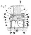
図1〜図5は、穿刺ヘッドを穿刺するための本発明の第1の実施の形態に係る穿刺デバイスの垂直断面図であり、この穿刺デバイスを使用して穿刺を実行する過程で生じる様々な状態を示したものである。 1 to 5 are vertical sectional views of a puncture device according to the first embodiment of the present invention for puncturing a puncture head, and various kinds of processes that occur in the process of performing puncture using the puncture device are shown. It shows the state.
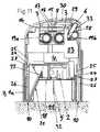
図1及び図2は、穿刺ヘッドが装着されていない穿刺デバイス(図1)と、穿刺ヘッドを装着した後の穿刺デバイス(図2)とを示した図であり、図示した状態は、穿刺を実行可能な状態ではない、通常時の状態である。図1及び図2から明らかなように、この穿刺デバイスは、ハウジング1と、このハウジング1の中に移動可能に配設されたピストン形状の打撃部材4と、コイルバネ3として構成されこの打撃部材4を駆動するためのたエネルギ蓄積部材とを備えている。打撃部材4は、その下面に、この穿刺デバイスを使用して穿刺しようとする穿刺ヘッドをその中に装着するための凹部12(図1参照)を有している。この装着は、穿刺ヘッドを凹部12の中に圧入することにより行われ、図示例では、穿刺ヘッドは注入セット2(図2参照)として構成されている。また、凹部12は、特許請求の範囲に記載した保持手段に相当するものである。注入セット2が、図2に示した状態でハウジング1の中に装着されているときには、注入カニューラ5(図2では見えていない)の外周に保護部材であるニードル・ガード14が嵌合されており、これによって、ユーザがカニューラ5により自傷する事態を防止するための保護がなされている。打撃部材4は、その上面に、把持部9を備えている。この把持部9を把持して引上げることによって、コイルバネ3の弾発力に抗して打撃部材4をハウジング1に対して相対的に上方へ引上げることができ、それによって、コイルバネ3を蓄勢状態にすることができる。この穿刺デバイスは更に、特許請求の範囲に記載した第1の操作部材と、同じく特許請求の範囲に記載した更なる2つの操作部材とを備えている。第1の操作部材は、安全ロック用スライド部材7として構成されており、更なる2つ操作部材は、トリガ・ボタン6a、6bとして構成されている。図1及び図2の状態にあるときには、安全ロック用スライド部材7によって、トリガ・ボタン6a、6bの操作が阻止されている。安全ロック用スライド部材7は、その上端に、復帰バネ13から下向きの弾発力が作用している。また、安全ロック用スライド部材7は、その下端に、リング形の当接面10を有しており、注入セット2の穿刺を実行する際には、この当接面10を患者の身体11に当接させて、穿刺デバイスを患者の身体11上に載置して押し付けるようにする。 1 and 2 are diagrams showing a puncture device (FIG. 1) to which a puncture head is not attached, and a puncture device (FIG. 2) after the puncture head is attached. This is a normal state that is not executable. As is apparent from FIGS. 1 and 2, the puncture device is configured as a
穿刺デバイスに装着した注入セット2の穿刺を実行するために、図2に示した状態にある穿刺デバイスを、図3に示したように、蓄勢状態にあって穿刺が実行可能な状態にするには、先ず、粘着剤層18の表面に貼付されている剥離シート(リリースライナー)を除去し、続いて、把持部9を把持して引上げることにより、打撃部材4をコイルバネ3の弾発力に抗してハウジング1に対して相対的に上方へ引上げ、この打撃部材4に形成されている2つの係止部8を、ハウジング1に一体的に形成されている2本の弾性アーム部16の2つの係止突起15に係合させる。これによって、コイルバネ3及び打撃部材4が、蓄勢状態にあって穿刺が可能な状態となる。また、このとき注入セット2は、特許請求の範囲に記載した第1位置に位置しており、注入カニューラ5は、当接面10よりもハウジング1の中の方に引っ込んでいる。続いて、注入カニューラ5から保護部材であるカニューラ・ガード14を除去すれば、この穿刺デバイスとこの穿刺デバイスに装着された注入セット2とから成る穿刺アセンブリは、穿刺が実行可能な状態になる。尚、図から明らかなように、この状態ではまだ、2つのトリガ・ボタン6a、6bを操作して径方向内方へ移動させることは、安全ロック用スライド部材7によって阻止されており、不可能となっている。 In order to execute the puncture of the infusion set 2 attached to the puncture device, the puncture device in the state shown in FIG. 2 is put into a state where the puncture can be performed in the stored state as shown in FIG. First, the release sheet (release liner) affixed to the surface of the pressure-
注入セット2の穿刺を実行する際には、穿刺デバイスの当接面10を患者の身体11の穿刺部位に当接させて、この穿刺デバイスを患者の身体11に押し付けるようにすれば、それによって安全用スライド部材7が、復帰バネ13の弾発力に抗してハウジング1の中へ押し込まれるように移動させられ、それによって、この安全ロック用スライド部材7に形成されている2つの開口17が、2つのトリガ・ボタン6a、6bと重なる位置へ移動し、その結果として、それらトリガ・ボタン6a、6bを径方向内方へ移動させて弾性アーム16を押動することが可能な状態になる。この状態を示したのが図4であり、この状態では、トリガ・ボタン6a、6bの操作阻止状態が解除されている。 When performing the puncture of the infusion set 2, if the
この状態から、特許請求の範囲に穿刺運動として記載した注入セット2の運動をトリガするには、即ち、注入セット2を特許請求の範囲に記載した第1位置である図3及び図4に示した位置からコイルバネ3の弾発力によって下方へ駆動して、注入カニューラ5を患者の身体11に穿刺するには、2つのトリガ・ボタン6a、6bを押圧して径方向内方へ移動させることで、それらトリガ・ボタン6a、6bと共に2本の弾性アーム16を移動させて、それら弾性アーム16の各々に1つずつ形成された2つの係止突起15を打撃部材4の2つの係止部8から脱係合させるようにすればよく、それによって打撃部材4が、この打撃部材4に装着された注入セット2と共に、コイルバネ3の弾発力により駆動されて下方へ射出される。この穿刺運動の開始時点の状態を示したのが図5である。 From this state, to trigger the movement of the infusion set 2 described as a puncture movement in the claims, that is, the infusion set 2 is shown in FIGS. 3 and 4 which is the first position described in the claims. In order to puncture the
図から明らかなように、注入セット2は、その下面に固定用の粘着剤層18を備えている。粘着剤層18は、穿刺された注入セット2を患者の皮膚に固定して、その穿刺の後に穿刺デバイスが患者の身体11から離される際に、注入セット2が打撃部材4の凹部12から外れて患者の身体11の穿刺部位に残置されるようにするものである。 As is apparent from the figure, the infusion set 2 includes a fixing
穿刺デバイスを患者の身体11から離した後に、トリガ・ボタン6a、6bから指先を離すと、トリガ・ボタン6a、6bは復帰バネ(不図示)に駆動されて径方向外方へ移動する。すると、安全ロック用スライド部材7が、復帰バネ13に駆動されて、図1〜図3に示したこの安全ロック用スライド部材7の安全ロック位置へ復帰する。これによって穿刺デバイスは、図1に示した状態に戻り、注入セット2の穿刺を実行するために再び使用することができるようになる。 When the fingertip is released from the trigger buttons 6a and 6b after the puncture device is released from the patient's
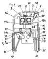
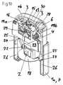
図6〜図13は、本発明の第2の実施の形態に係る穿刺デバイスの垂直断面図であり、それらの図は、この穿刺デバイスを使用して穿刺を実行する際に生じる様々な状態を示しており、特に図10は、この穿刺デバイスを垂直平面に沿って部分的に破断した斜視図を示したものである。 6 to 13 are vertical sectional views of the puncture device according to the second embodiment of the present invention, and these drawings show various states that occur when performing puncture using this puncture device. In particular, FIG. 10 shows a perspective view in which the puncture device is partially broken along a vertical plane.
図6及び図7は、穿刺ヘッドを装着していない穿刺デバイスを示した図であり、一方は非蓄勢状態(図6)にある穿刺デバイスを示し、他方は蓄勢状態(図7)にある穿刺デバイスを示している。図6及び図7から明らかなように、この穿刺デバイスは、2つのハウジング構成部品1a、1bにより構成されたハウジングを備えており、それら2つのハウジング構成部品1a、1bは押圧されることで短縮状態とされるように構成されている。この穿刺デバイスは更に、上側ハウジング構成部品1bの中に鉛直方向に移動可能に配設された打撃部材4を備えており、この打撃部材4は、機械的に連動するようにした一対の回動レバー19a、19bにより駆動される。一対の回動レバー19a、19bには、特許請求の範囲に記載したエネルギ蓄積部材がその各々に1つずつ装備されている。図示例では、それら2つのエネルギ蓄積部材は、2つのねじりコイルバネ3として構成されている。それらねじりコイルバネ3は、夫々に対応した回動レバー19a、19bに係合しており、打撃部材4を駆動して前方へ押出すように機能する。図7の状態では、打撃部材4は上側ハウジング構成部材1bの中に収容されており、2つのねじりコイルバネ3は蓄勢状態とされている。図示例では、この穿刺デバイスを使用して穿刺する穿刺ヘッドは、注入セット2として構成されている。上側ハウジング構成部材1bは、注入セット2を押し込んで保持させることができるようにした、互いに対向した2つの弾性留め具12(ただし、図にはその一方しか見えていない)を備えている。それら弾性留め具12はハウジングに取付けられており、特許請求の範囲に記載した保持手段として機能するものであり、注入セット2を保持させるには、それら2つの弾性留め具12の間に注入セット2を挟み込むようにする。従ってこの実施の形態では、注入セット2は、上側ハウジング構成部材1bの中に装着されて保持されるようにしてあり、その点において、上で説明した第1の実施の形態のように、注入セット2が打撃部材4に装着されてハウジングに対して相対的に移動するものとは異なっている。図6から明らかなように、この実施の形態では、打撃部材4の2本のアーム20a、20bを、下側ハウジング構成部材1aに形成した2つの支持面の夫々に当接させてあるため、この図6に示した状態から、2つのハウジング構成部材1a、1bを押圧して短縮状態にすることにより、打撃部材4をねじりコイルバネ3の弾発力に抗して上側ハウジング構成部材1bの中へ移動させることができ、それによって、この打撃部材4の頂部に設けた弾性アーム16の係止突起15を、上側ハウジング構成部材1bに形成された係止部8に係合させることができる。この状態を示したのが図7であり、この状態では、2つのねじりコイルバネ3と、それらコイルバネ3によって駆動される打撃部材4とが、蓄勢状態とされており、穿刺が実行可能な状態となっている。 6 and 7 are diagrams showing a puncture device without a puncture head, one showing the puncture device in the non-energized state (FIG. 6) and the other in the energized state (FIG. 7). 1 shows a lancing device. As is apparent from FIGS. 6 and 7, the puncture device includes a housing constituted by two
穿刺デバイスがこの状態にあるときに、注入セット2をその穿刺デバイスに装着して、上側ハウジング構成部材1bに保持させることができ、それには、注入セット2を2つの弾性留め具12の間に挟み込むようにすればよい。こうして注入セット2を装着した状態を示したのが図8である。 When the puncture device is in this state, the infusion set 2 can be attached to the puncture device and held on the
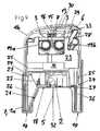
図9及び図10は、図8に示した穿刺デバイスを示した図であるが、ただしそれらの図に示した状態は、図8の状態に続く次の状態であって、2つのハウジング構成部材1a、1bが伸長状態とされ、注入セット2の穿刺が実行可能になった状態を示している。図8と、図9及び図10とを見比べれば明らかなように、この実施の形態における注入セット2は、突出式の注入カニューラ5を備えたものである。図8から明らかなように、蓄勢状態にある穿刺デバイスに注入セット2を装着するときには、注入カニューラ5は注入セット2の二分割型ハウジングの中に引っ込んで隠れている。この図8の状態から、穿刺デバイスの2つのハウジング構成部材1a、1bを伸長状態にすると、注入セット2の二分割式ハウジングが圧縮されて、その内部機構によって注入カニューラ5が突出させられる。この状態になったとき、注入セット2は特許請求の範囲に記載した第1位置に位置しており、そして、この状態を示したのが図9及び図10である。注入セット2の二分割式ハウジングの圧縮は、水平方向に移動可能な突き当て部材22に対して、下側ハウジング構成部材1aに形成された傾斜面21が、相対的に鉛直方向に移動することにより発生する。即ち、この傾斜面21の相対移動によって、突き当て部材22は注入セット2の二分割式ハウジングのうちの左側ハウジング構成部材へ向けて移動させられ、その結果、注入セット2の二分割式ハウジングのうちのこの左側ハウジング構成部材が、注入セット2の二分割式ハウジングのうちの右側ハウジング構成部材の中へ押し込まれ、それによって注入セット2の二分割式ハウジングが圧縮状態になるのである。 9 and 10 show the puncture device shown in FIG. 8, except that the state shown in these figures is the next state following the state of FIG. 1a and 1b are in an extended state, and a state in which puncture of the infusion set 2 can be performed is shown. As is apparent from a comparison between FIG. 8 and FIGS. 9 and 10, the injection set 2 in this embodiment includes a protruding
また更に、図8と、図9及び図10とを見比べればこれも明らかなように、穿刺デバイスを蓄勢状態にした後に、以上に説明したように、穿刺デバイスの2つのハウジング構成部材1a、1bを伸長状態とすることによって、ハウジング内に配設されているロック用スライド部材23が、下側ハウジング構成部材1aに連結するようにしてある。この連結状態は、ロック用スライド部材23の一対の弾性アーム25の各々に1つずつ形成された一対の係止突起24が、下側ハウジング構成部材1aの一対の係止部27の夫々に係合することによって生じるものである。また、ロック用スライド部材23の一対の係止突起24は、下側ハウジング構成部材1aの内面に形成された鉛直方向に延在する一対の案内溝26に嵌合されており、鉛直方向に移動可能とされている。図6〜図10に示した状態では、ロック用スライド部材23が安全ロック位置にあり、このロック用スライド部材2によって、特許請求の範囲に記載した操作部材である穿刺デバイスに設けられたトリガ・ボタン6の操作が阻止されており、それが阻止されているのは、ロック用スライド部材23の安全ロック用係止部29によって、トリガ・ボタン6に固定連結された案内ロッド28の操作方向の移動が阻止されているからである。 Furthermore, as is clear from comparing FIG. 8, FIG. 9 and FIG. 10, after the puncture device is stored, as described above, the two
ロック用スライド部材23と、この穿刺デバイスの下側ハウジング構成部材1aとを、以上に説明したように互いに連結した状態としたならば、それに続いて、2つのハウジング構成部材1a、1bを押圧して半ば短縮状態とすることで、ロック用スライド部材23を上側ハウジング構成部材1bに対して相対的に移動させるようにする。これによって、それまで案内ロッド28の移動を阻止していた安全ロック用係止部29が、この案内ロッド28を解放するため、トリガ・ボタン6を操作方向に移動させることが可能となり、即ち、トリガ・ボタン6の操作阻止状態が解除される。以上の操作を行うときの、ロック用スライド部材23の上側ハウジング構成部材1bに対する相対的な移動量は、小さなものでしかなく、そのため、2つのハウジング構成部材1a、1bの短縮量も、注入カニューラ5を当接面10より前方へ突出させてしまうほど大きなものとはならず、それゆえ、自傷のおそれをもたらす注入カニューラ5の突出は発生しない。以上の操作を行ったときの状態を示したのが図11であり、この状態は、下側ハウジング構成部材1aの下面に形成した特許請求の範囲に記載した当接面10を患者の身体11に当接させて、穿刺デバイスを患者の身体11に押し付け、それによって2つのハウジング構成部材1a、1bを半ば短縮状態とすることで、安全ロック用スライド部材23を移動させて、トリガ・ボタン6を安全ロック解除状態とした状態である。従って、下側ハウジング構成部材1aは、安全ロック用スライド部材23と連結することによって、特許請求の範囲に記載した第1の操作部材7を構成するものである。 If the
図11に示したこの状態から、トリガ・ボタン6の押下操作を行うと、トリガ・ロッド30が、打撃部材4の弾性アーム16を押動して撓ませ、打撃部材4の係止突起15を左方へ移動させるため、係止突起15が上側ハウジング構成部材1bの係止部8から脱係合し、それによって打撃部材4が下方へ向けて射出される。この打撃部材4の射出動作は、一対の回動レバー19a、19bによって案内され、また、蓄勢状態とされていた一対のねじりコイルバネ3の弾発力によって駆動されて行われる動作である。射出された打撃部材4は、一対の弾性留め具12の間の保持されている注入セット2を打撃して、この注入セット2を穿刺部位へ打ちつける。これによって、注入カニューラ5がその根元まで患者の身体11に穿刺され、それと同時に、注入セット2の下面に設けられている固定用の粘着剤層18が、注入セット2を患者の皮膚に固定する。この状態となったとき、注入セット2は既に穿刺デバイスから分離しており、この状態を示したのが図12である。この状態から、穿刺デバイスを患者の身体11から離し、そして、トリガ・ボタン6を押下操作していた指先をトリガ・ボタン6から離したならば、トリガ・ボタン6は、復帰バネ33(図6、図9、図11、及び図13だけに示した)の作用によってその初期位置である非操作位置へ復帰し、また、安全ロック用スライド部材23は、それに装備されている復帰バネ13の作用によってその初期位置である安全ロック位置へ復帰する。安全ロック用スライド部材23が初期位置へ復帰するのは、穿刺デバイスがもはや患者の身体11に押し付けられておらず、そのため2つのハウジング構成部材1a、1bが完全に伸長した状態となっているからである。また、安全ロック用スライド部材23が初期位置へ復帰するのに伴って、このロック用スライド部材23の2本の弾性アーム25が打撃部材4の2本のアーム20a、20bによって撓ませられ、そのためロック用スライド部材23の2つの係止突起24が外側へ外方へ変位して、下側ハウジング構成部材1aの2つの係合部27から脱係合する。穿刺デバイスを患者の身体11から離して持上げることによって生じるこの状態を示したのが図13である。このとき穿刺デバイスは、図6に示した初期状態に復帰しており、再び注入セット2の穿刺を行うために使用可能な状態になっている。 When the
ここで、第1の実施の形態と第2の実施の形態とに共通する事項について述べると、それらのいずれにおいても、注入ヘッドは、図示したように可撓性カニューラ5(ソフト・カニューラ)を備えた注入セット2として構成されており、更に、それら注入セット2のいずれも、その可撓性カニューラ5は、ガイド・ニードル32によって支持されている。穿刺の後には、そのガイド・ニードル32と、注入セット2の構成部品のうちそのガイド・ニードル32に結合している構成部品とが除去され(それらが除去された状態は図示していない)、そして、注入セット2の除去されずに残置された部分に、注入チューブが接続され、その注入チューブを介して患者の身体11の中へ注入液が注入される。 Here, the matters common to the first embodiment and the second embodiment will be described. In any of them, the injection head uses the flexible cannula 5 (soft cannula) as shown in the figure. Each of the infusion sets 2 has a
図14及び図15は、本発明の第3の実施の形態に係る穿刺デバイスを部分的に破断して示した垂直断面図であり、図14は、この穿刺デバイスが蓄勢状態にあり、且つ、安全ロック状態にあるところを示しており、図15は、この穿刺デバイスを患者の身体11上に載置して押し付けることで、安全ロック解除状態としたところを示している。この実施の形態は、以下に説明する相違点を除いて、基本的に、図6〜図13に示した第2の実施の形態に対応した構成とされている。また、図14及び図15に示した2通りの動作状態は、夫々、図9及び図11に示した2通りの動作状態に対応しているが、ただし図14及び図15では、図を見易くするために、穿刺デバイスに装着される穿刺ヘッドを不図示とした。 FIGS. 14 and 15 are vertical sectional views showing a puncture device according to a third embodiment of the present invention, partially broken away, and FIG. 14 shows that the puncture device is in a stored state, and FIG. 15 shows a place where the puncture device is placed on the patient's
本発明の第3の実施の形態に係るこの穿刺デバイスが、先に説明した第2の実施の形態と基本的に異なる点は、この第3の実施の形態では、操作ボタン6を操作阻止状態とするために、ロック用スライド部材23が操作ボタン6の案内ロッド28の移動を阻止するようにするのではなく、ロック用スライド部材23が安全ロック位置にあるときに、このロック用スライド部材23が、打撃部材4の弾性アーム16が撓むのを阻止し、もって、係止突起15が上側ハウジング構成部材1bの係止部8から脱係合できないようにすることで、操作ボタン6を操作阻止状態にするようにしていることである。この操作阻止状態を示したのが図14である。この状態から、第2の実施の形態に関連して説明したのと同様にして、下側ハウジング構成部材1aの当接面10を患者の身体11に当接させて、この穿刺デバイスを患者の身体11に押し付けることによって、ロック用スライド部材23を上側ハウジング構成部材1bの中で上方へ移動させることができ、そうすれば、弾性アーム16が撓むのを阻止していたロック用スライド部材23の突き当て部31が、弾性アーム16を解放する。この状態で操作ボタン6を押下操作することによって、係止突起15を係止部8から脱係合させることができ、それによって穿刺デバイスがトリガされる。この穿刺デバイスの以上に説明した以外の諸機能及び諸動作モードは全て、第2の実施の形態に関連して説明したものと同じである。 The puncture device according to the third embodiment of the present invention is basically different from the second embodiment described above in that the
図16に示したのは、本発明の第4の実施の形態に係る穿刺デバイスの垂直断面図であって、この穿刺デバイスが蓄勢状態にあり、この穿刺デバイスに注入セット2が装着されており、且つ、この穿刺デバイスが安全ロック状態にあるところを示した図である。 FIG. 16 is a vertical sectional view of the puncture device according to the fourth embodiment of the present invention, in which the puncture device is in a stored state and the infusion set 2 is attached to the puncture device. FIG. 2 is a view showing the puncture device in a safety lock state.
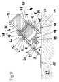
この実施の形態に係る穿刺デバイスが、図1〜図5の穿刺デバイスと異なる点は、傾斜穿刺用に製作された注入セットを傾斜穿刺するための穿刺デバイスとして構成されていることである。傾斜穿刺用に製作された注入セットであるため、カニューラ5及びガイド・ニードル32の穿刺方向が穿刺部位の皮膚表面に対して成す角度αが、90°より小さな角度となっている。この角度αは、20°〜45°の角度とすることが好ましい。図示例では、この角度αを45°としている。傾斜穿刺するための穿刺デバイスであるため、この穿刺デバイスのハウジング1及び安全ロック用スライド部材7は、図1〜図5に示した穿刺デバイスのハウジング1及び安全ロック用スライド部材7に対して変更を加えたものとなっている。また、更なる相違点として、この穿刺デバイスでは、打撃部材4に注入セット2を装着するための装着部が、アダプタ34で構成されているということがある。 The puncture device according to this embodiment is different from the puncture device of FIGS. 1 to 5 in that it is configured as a puncture device for tilting and puncturing an infusion set manufactured for tilted puncture. Since the injection set is manufactured for inclined puncture, the angle α formed by the puncture directions of the
この穿刺デバイスの以上に説明した以外の諸構成要素及び諸動作形態は、図1〜図5の穿刺デバイスの諸構成要素及び諸動作形態と同じであるため、それらについての詳細は、図1〜図5に関連した先の説明を参照されたい。 The components and operation modes of the puncture device other than those described above are the same as the components and modes of operation of the puncture device of FIGS. Reference is made to the previous description in connection with FIG.
図17に示したのは、本発明の第5の実施の形態に係る穿刺デバイスの垂直断面図であって、この穿刺デバイスが蓄勢状態にあり、この穿刺デバイスに注入セット2が装着されており、且つ、この穿刺デバイスが安全ロック状態にあるところを示した図である。 FIG. 17 is a vertical sectional view of the puncture device according to the fifth embodiment of the present invention, in which the puncture device is in a stored state and the infusion set 2 is attached to the puncture device. FIG. 2 is a view showing the puncture device in a safety lock state.
この実施の形態に係る穿刺デバイスが図16の穿刺デバイスと異なる点は、注入セット2を打撃部材4に装着するのではなく、この穿刺デバイスのハウジング1の中のフレーム部35とアダプタ部材34とで注入セット2を保持するようにしていることである。この実施の形態におけるアダプタ部材34は、基本的に、外周に溝を備えた円板形の部材である。 The puncture device according to this embodiment is different from the puncture device of FIG. 16 in that the infusion set 2 is not attached to the striking
打撃部材4はその前端面がハンマーを形成している。安全ロック状態を解除してトリガ・ボタン6a、6bを操作すると、この打撃部材4が、バネ3の弾発力によって下方へ駆動されてアダプタ部材34を打撃し、このアダプタ部材34をフレーム部35から離脱させ、そして、このアダプタ部材34を注入セット2と諸共に穿刺部位へ打ちつける。これによって、注入カニューラ5及び穿刺ニードル32がそれらの根元まで患者の身体11に穿刺される。 The front end surface of the striking
図18に示したのは、本発明の第6の実施の形態に係る穿刺デバイスの垂直断面図であって、この穿刺デバイスが蓄勢状態にあり、この穿刺デバイスに注入セット2が装着されており、且つ、この穿刺デバイスが安全ロック状態にあるところを示した図である。 FIG. 18 is a vertical cross-sectional view of the puncture device according to the sixth embodiment of the present invention, in which the puncture device is in a stored state and the infusion set 2 is attached to the puncture device. FIG. 2 is a view showing the puncture device in a safety lock state.
この実施の形態に係る穿刺デバイスが図16の穿刺デバイスと異なる点は、この穿刺デバイスを使用して穿刺する注入セット2が、カニューラ5及び穿刺ニードル32を傾斜可能とした注入セット2であることである。図18に示した状態は、注入カニューラ5及び穿刺ニードル32が、注入セット2のハウジングの中に収容されて隠されていた収容状態から既に引き出されて、傾斜して突出した状態となっているところを示したものである。 The puncture device according to this embodiment is different from the puncture device of FIG. 16 in that the infusion set 2 for puncturing using the puncture device is an infusion set 2 in which the
図から明らかなように、この実施の形態では、注入セット2は、打撃部材4に装着されるのではなく、クランプ用スリーブ部材36によって保持されており、このクランプ用スリーブ部材36は、複数本の弾性アーム37によって注入セット2を保持している。打撃部材4は、クランプ用スリーブ部材36の中に配設されており、この打撃部材4に形成された2つの把持部9が、クランプ用スリーブ部材36を貫通して径方向外方へ突出している。 As is apparent from the figure, in this embodiment, the infusion set 2 is not attached to the striking
クランプ用スリーブ部材36及び打撃部材4は、注入セット2を装着するための装着位置(不図示)にあるとき、ハウジング1の中の最もハウジング1の先端寄りに位置している。注入セット2をクランプ用スリーブ部材36に装着したならば、把持部9を把持して引上げるようにして、打撃部材4及びクランプ用スリーブ部材36を共に後方へ移動させることによって、クランプ用スリーブ部材36の内面に形成されている複数の係止部38をハウジング1に係合させるようにし、これによってクランプ用スリーブ部材36がハウジング1に係止される。 When the clamping
また、このようにクランプ用スリーブ部材36を後方へ移動させる際に、注入セット2のハウジングを構成している2つのハウジング構成部材が、穿刺デバイスのハウジング1の内面に形成されている傾斜面21によって圧縮状態とされ、それに伴って、この注入セット2の内部機構によって注入カニューラ5及び穿刺ニードル32が突出させられる。 Further, when the clamping
続いて、安全ロック状態を解除してトリガ・ボタン6a、6bを操作すると、打撃部材4が、バネ3の弾発力によって下方へ駆動され、複数本の弾性アーム37の夫々の内側に形成されているカム部39に当接してそれら弾性アーム37が押し広げることで注入セット2をそれら弾性アーム37から離脱させ、そして、その離脱させた注入セット2を打撃して穿刺部位へ打ちつける。これによって、注入カニューラ5及び穿刺ニードル32が、それらの根元まで患者の身体11に穿刺される。 Subsequently, when the safety lock state is released and the trigger buttons 6a and 6b are operated, the striking
以上に具体例として示した実施の形態はいずれも、それらを使用して穿刺する穿刺ヘッドが注入セットとして構成されたものであった。しかしながら、以上に示した穿刺デバイスは、注入セット以外のその他の構成とした穿刺ヘッドを穿刺するためにも用い得るものであることをここで述べておく。例えば、注入ポートとして構成された穿刺ヘッド、センサ・アセンブリとして構成された穿刺ヘッド、或いはまた、センサ・アセンブリと、注入ポートまたは注入セットとを組合せて構成した穿刺ヘッドを穿刺するためにも用いることができ、また更に、本発明は、ニードルに類似した部材、またはブレードに類似した部材を患者の体内に穿刺するように構成された、考え得る限りのあらゆる種類の穿刺ヘッドに適用し得るものである。 In all of the embodiments described above as specific examples, the puncture head for puncturing using them is configured as an infusion set. However, it should be mentioned here that the puncture device shown above can also be used to puncture puncture heads other than infusion sets. For example, it may be used to puncture a puncture head configured as an injection port, a puncture head configured as a sensor assembly, or alternatively a combination of a sensor assembly and an injection port or infusion set. In addition, the present invention is applicable to all possible types of puncture heads configured to puncture a patient-like member or a member similar to a blade into a patient's body. is there.
更には、以上に具体例として示した夫々の実施の形態に関連して個々に説明した様々な技術的解決手段を、適宜組合せて用いることも想定のうちである。例えば、図1〜図5に示した第1の実施の形態に係る穿刺デバイスにおいて、その穿刺ヘッドを打撃部材に保持させることに代えて、図6〜図13に示した第2の実施の形態のように、その穿刺ヘッドを打撃部材とは別個にハウジングに保持させるようにしてもよい。 Furthermore, it is also assumed that various technical solutions described individually in relation to the respective embodiments shown as specific examples above are used in appropriate combination. For example, in the puncture device according to the first embodiment shown in FIGS. 1 to 5, instead of holding the puncture head by the striking member, the second embodiment shown in FIGS. 6 to 13. As described above, the puncture head may be held in the housing separately from the striking member.
Claims (21)
Translated fromJapanesea)患者の身体(11)の前記穿刺ヘッド(2)を穿刺しようとする部位である穿刺部位に該穿刺デバイスを載置するための少なくとも1つの当接面(10)を備え、
b)穿刺しようとする前記穿刺ヘッド(2)を一時的に該穿刺デバイスに保持させるための保持手段(12)を備え、
c)前記穿刺ヘッド(2)の穿刺運動を発生させる駆動手段(3、4)を備え、該穿刺運動は前記当接面(10)に対する前記穿刺ヘッド(2)の相対的な運動であり、該穿刺運動の運動方向は前記注入カニューラ(5)または前記穿刺チップの長手方向であり、該穿刺運動は、前記注入カニューラ(5)または前記穿刺チップが前記当接面(10)に対して相対的に引っ込んだ状態で前記穿刺ヘッド(2)が前記保持手段(12)によって保持されている第1位置から、前記注入カニューラ(5)または前記穿刺チップが前記当接面(10)から略々完全に突出した状態となる第2位置への運動であり、該穿刺デバイスの前記当接面(10)を患者の身体(11)に当接させて該穿刺デバイスを載置して該穿刺運動を行わせることで、前記注入カニューラ(5)または前記穿刺チップが患者の身体(11)に穿刺されるようにしてあり、
該穿刺デバイスは、前記穿刺運動をトリガするためには同時に操作する必要のある少なくとも2つの操作部材(6、6a、6b、7)を備えており、それら少なくとも2つの操作部材のうちの第1の操作部材(7)は、該穿刺デバイスの前記当接面(10)を患者の身体(11)に押し付けることで操作されるように構成されており、その際の押し付ける方向は特に前記穿刺デバイス(2)の前記穿刺運動の方向などである、
ことを特徴とする穿刺デバイス。In a puncture device for puncturing an infusion cannula (5) puncturing the patient's body (11) or a puncture head (2) with a puncture tip,
a) comprising at least one abutment surface (10) for placing the puncture device on a puncture site which is a site to be punctured with the puncture head (2) of the patient's body (11);
b) comprising holding means (12) for temporarily holding the puncture head (2) to be punctured by the puncture device;
c) comprises driving means (3, 4) for generating a puncturing movement of the puncturing head (2), the puncturing movement being a relative movement of the puncturing head (2) with respect to the abutment surface (10); The direction of movement of the puncture movement is the longitudinal direction of the injection cannula (5) or the puncture tip, and the puncture movement is performed when the injection cannula (5) or the puncture tip is relative to the contact surface (10). From the first position where the puncture head (2) is held by the holding means (12) in the retracted state, the injection cannula (5) or the puncture tip is approximately from the contact surface (10). It is a movement to the 2nd position which will be in the state where it protruded completely, and makes the said contact surface (10) of this puncture device contact a patient's body (11), and mounts this puncture device, and this puncture movement By performing ON cannula (5) or the piercing tip is Yes so as to be pierced into the patient's body (11),
The puncture device includes at least two operation members (6, 6a, 6b, 7) that need to be simultaneously operated to trigger the puncture movement, and the first of the at least two operation members. The operating member (7) is configured to be operated by pressing the abutment surface (10) of the puncture device against the patient's body (11). (2) the direction of the puncture movement, etc.
A puncture device characterized by that.
a)注入カニューラ(5)または穿刺チップを有する穿刺ヘッド(2)を保持手段(12)によって第1位置に保持して、前記穿刺デバイスを穿刺が実行可能な状態にするステップと、
b)前記穿刺運動によって前記穿刺ヘッド(2)の前記注入カニューラ(5)または前記穿刺チップが患者の身体(11)に適切に穿刺されるように、患者の身体(11)上の穿刺部位に前記当接面(10)を当接させて、前記穿刺デバイスを当該穿刺部位に位置付けて押し付け、それによって前記第1の操作部材(7)の操作を行うステップと、
c)前記第2の操作部材並びに更にその他の操作部材が存在するのであればその操作部材(6、6a、6b)も併せて操作して、前記穿刺運動をトリガするステップと、
を含むことを特徴とする方法。Use of the puncture device according to any one of claims 1 to 15 to puncture a head, and in particular a puncture head configured as an infusion set (2), an infusion port or a sensor assembly. In the method of puncturing the body,
a) holding the puncture head (2) having an infusion cannula (5) or a puncture tip in a first position by means of a holding means (12) to make the puncture device ready for puncture;
b) At the puncture site on the patient's body (11) so that the injection cannula (5) or the puncture tip of the puncture head (2) is properly punctured into the patient's body (11) by the puncture movement. Abutting the abutment surface (10), positioning and pressing the puncture device against the puncture site, thereby operating the first operating member (7);
c) triggering the puncture movement by operating the second operating member as well as other operating members, if any, in addition to operating the operating members (6, 6a, 6b);
A method comprising the steps of:
Applications Claiming Priority (2)
| Application Number | Priority Date | Filing Date | Title |
|---|---|---|---|
| CH13492006 | 2006-08-24 | ||
| PCT/CH2007/000400WO2008022476A1 (en) | 2006-08-24 | 2007-08-16 | Insertion device for insertion heads, in particular for infusion sets |
Publications (1)
| Publication Number | Publication Date |
|---|---|
| JP2010501211Atrue JP2010501211A (en) | 2010-01-21 |
Family
ID=38596829
Family Applications (1)
| Application Number | Title | Priority Date | Filing Date |
|---|---|---|---|
| JP2009524858APendingJP2010501211A (en) | 2006-08-24 | 2007-08-16 | Puncture device for puncturing a puncture head such as an infusion set |
Country Status (7)
| Country | Link |
|---|---|
| US (1) | US8870822B2 (en) |
| EP (1) | EP2054109B1 (en) |
| JP (1) | JP2010501211A (en) |
| CN (1) | CN101505816B (en) |
| CA (1) | CA2660392A1 (en) |
| DK (1) | DK2054109T3 (en) |
| WO (1) | WO2008022476A1 (en) |
Cited By (20)
| Publication number | Priority date | Publication date | Assignee | Title |
|---|---|---|---|---|
| WO2012046816A1 (en) | 2010-10-07 | 2012-04-12 | 久光製薬株式会社 | Applicator |
| WO2013051568A1 (en) | 2011-10-06 | 2013-04-11 | 久光製薬株式会社 | Applicator |
| JP2014069084A (en)* | 2012-09-27 | 2014-04-21 | Becton Dickinson & Co | Angled inserter for drug infusion |
| JP2014531922A (en)* | 2011-09-02 | 2014-12-04 | ユニトラクト シリンジ プロプライエタリイ リミテッドUnitract Syringe Pty Ltd | Insertion mechanism for drug delivery pump |
| JP2015518396A (en)* | 2012-04-11 | 2015-07-02 | ファルマセンス アクチェンゲゼルシャフト | Hypodermic needle insertion mechanism |
| JP2015526220A (en)* | 2012-09-04 | 2015-09-10 | サノフィ−アベンティス・ドイチュラント・ゲゼルシャフト・ミット・ベシュレンクテル・ハフツング | Drug delivery device with alignment mechanism |
| JP2016510639A (en)* | 2013-03-15 | 2016-04-11 | ベクトン・ディキンソン・アンド・カンパニーBecton, Dickinson And Company | Automatic tilting infusion set assembly |
| US9707335B2 (en) | 2011-09-02 | 2017-07-18 | Unitract Syringe Pty Ltd | Drive mechanism for drug delivery pumps with integrated status indication |
| US9707337B2 (en) | 2011-09-13 | 2017-07-18 | Unitract Syringe Pty Ltd | Sterile fluid pathway connection to drug containers for drug delivery pumps |
| US9737655B2 (en) | 2013-08-23 | 2017-08-22 | Unitract Syringe Pty Ltd | Integrated pierceable seal fluid pathway connection and drug containers for drug delivery pumps |
| US9802030B2 (en) | 2013-01-25 | 2017-10-31 | Unl Holdings Llc | Integrated sliding seal fluid pathway connection and drug containers for drug delivery pumps |
| US9814832B2 (en) | 2011-09-02 | 2017-11-14 | Unl Holdings Llc | Drive mechanism for drug delivery pumps with integrated status indication |
| US9999727B2 (en) | 2011-09-02 | 2018-06-19 | Unl Holdings Llc | Drive mechanism for drug delivery pumps with integrated status indication |
| US10251996B2 (en) | 2012-08-29 | 2019-04-09 | Unl Holdings Llc | Variable rate controlled delivery drive mechanisms for drug delivery pumps |
| USD886986S1 (en) | 2013-03-12 | 2020-06-09 | Unl Holdings Llc | Drug delivery pump |
| US10806855B2 (en) | 2014-09-29 | 2020-10-20 | Unl Holdings Llc | Rigid needle insertion mechanism for a drug delivery pump |
| US11033676B2 (en) | 2016-08-08 | 2021-06-15 | Unl Holdings Llc | Drug delivery device and method for connecting a fluid flowpath |
| US11173244B2 (en) | 2011-09-02 | 2021-11-16 | Unl Holdings Llc | Drive mechanism for drug delivery pumps with integrated status indication |
| JP2022521293A (en)* | 2019-02-22 | 2022-04-06 | デカ・プロダクツ・リミテッド・パートナーシップ | Injection set and inserter assembly system and method |
| JP2022546459A (en)* | 2019-08-27 | 2022-11-04 | エルテーエス ローマン テラピー-ジステーメ アーゲー | Microarray applicator and method for moving plunger to act on microarray |
Families Citing this family (70)
| Publication number | Priority date | Publication date | Assignee | Title |
|---|---|---|---|---|
| US20190357827A1 (en) | 2003-08-01 | 2019-11-28 | Dexcom, Inc. | Analyte sensor |
| US7731691B2 (en) | 2003-11-10 | 2010-06-08 | Smiths Medical Asd, Inc. | Subcutaneous infusion device and device for insertion of a cannula of an infusion device and method |
| WO2009048462A1 (en) | 2007-10-09 | 2009-04-16 | Dexcom, Inc. | Integrated insulin delivery system with continuous glucose sensor |
| US8029441B2 (en) | 2006-02-28 | 2011-10-04 | Abbott Diabetes Care Inc. | Analyte sensor transmitter unit configuration for a data monitoring and management system |
| US9788771B2 (en) | 2006-10-23 | 2017-10-17 | Abbott Diabetes Care Inc. | Variable speed sensor insertion devices and methods of use |
| US8512243B2 (en) | 2005-09-30 | 2013-08-20 | Abbott Diabetes Care Inc. | Integrated introducer and transmitter assembly and methods of use |
| ES2820335T3 (en) | 2007-04-16 | 2021-04-20 | Corium Inc | Solvent Cast Microneedle Arrays Containing Active Agent |
| WO2009048607A1 (en) | 2007-10-10 | 2009-04-16 | Corium International, Inc. | Vaccine delivery via microneedle arrays |
| US9295786B2 (en) | 2008-05-28 | 2016-03-29 | Medtronic Minimed, Inc. | Needle protective device for subcutaneous sensors |
| GB2461088B (en) | 2008-06-19 | 2012-09-26 | Cilag Gmbh Int | Injection device |
| US9402544B2 (en) | 2009-02-03 | 2016-08-02 | Abbott Diabetes Care Inc. | Analyte sensor and apparatus for insertion of the sensor |
| EP3001194B1 (en) | 2009-08-31 | 2019-04-17 | Abbott Diabetes Care, Inc. | Medical devices and methods |
| ATE553800T1 (en)* | 2009-11-26 | 2012-05-15 | Hoffmann La Roche | EXTERNALLY TRIGGERABLE CANNULA ARRANGEMENT |
| USD924406S1 (en) | 2010-02-01 | 2021-07-06 | Abbott Diabetes Care Inc. | Analyte sensor inserter |
| LT3622883T (en) | 2010-03-24 | 2021-08-25 | Abbott Diabetes Care, Inc. | Medical device inserters and processes of inserting and using medical devices |
| WO2011140274A2 (en) | 2010-05-04 | 2011-11-10 | Corium International, Inc. | Method and device for transdermal delivery of parathyroid hormone using a microprojection array |
| WO2011160244A1 (en)* | 2010-06-21 | 2011-12-29 | F. Hoffmann-La Roche Ag | Device for inserting an insertion member into the tissue of the body of a patient |
| EP2697650B1 (en) | 2011-04-15 | 2020-09-30 | Dexcom, Inc. | Advanced analyte sensor calibration and error detection |
| EP2713879B1 (en) | 2011-12-11 | 2017-07-26 | Abbott Diabetes Care, Inc. | Analyte sensor devices, connections, and methods |
| EP2858699A1 (en)* | 2012-06-09 | 2015-04-15 | Roche Diagnostics GmbH | Disposable inserter for use with a medical device |
| EP2716317A1 (en) | 2012-10-04 | 2014-04-09 | Sanofi-Aventis Deutschland GmbH | Medicament delivery device with trigger button |
| BR112015014969B1 (en) | 2012-12-21 | 2021-12-07 | Corium, Inc | MICROSTRUCTURE APPARATUS AND METHOD OF MANUFACTURING A MICROSTRUCTURE APPARATUS |
| EP2968887B1 (en)* | 2013-03-12 | 2022-05-04 | Corium, Inc. | Microprojection applicators |
| US10080839B2 (en) | 2013-03-14 | 2018-09-25 | Becton, Dickinson And Company | Angled inserter for drug infusion |
| CA2903763C (en) | 2013-03-15 | 2021-11-16 | Corium International, Inc. | Microarray with polymer-free microstructures, methods of making, and methods of use |
| ES2939317T3 (en) | 2013-03-15 | 2023-04-20 | Corium Pharma Solutions Inc | Multi-impact micro-spray applicators |
| BR112015022625B1 (en) | 2013-03-15 | 2023-01-31 | Corium, Inc | MICROSTRUCTURE DEVICE FOR DELIVERY OF THERAPEUTIC AGENT |
| EP2968771A4 (en)* | 2013-03-15 | 2017-02-15 | University Hospitals Case Medical Center | Subcutaneous hydration system, method, and device |
| AU2014233541B2 (en) | 2013-03-15 | 2018-11-22 | Corium Pharma Solutions, Inc. | Microarray for delivery of therapeutic agent, methods of use, and methods of making |
| US10478569B2 (en)* | 2013-04-07 | 2019-11-19 | Repro-Med Systems, Inc. | Needle insertion device |
| US11559635B2 (en)* | 2015-10-07 | 2023-01-24 | Repro-Med Systems, Inc. | Needle insertion device |
| US11883638B2 (en)* | 2013-04-07 | 2024-01-30 | Koru Medical Systems, Inc. | Needle insertion device |
| WO2014178140A1 (en)* | 2013-05-02 | 2014-11-06 | Asti株式会社 | Microneedle array and microneedle array device |
| WO2015136639A1 (en) | 2014-03-12 | 2015-09-17 | 株式会社バイオセレンタック | Micro-needle preparation administration member for intradermal placement of target substance and apparatus for rapid administration of micro-needle preparation |
| CH709930A2 (en) | 2014-07-29 | 2016-01-29 | Tecpharma Licensing Ag | Insertion device for an infusion. |
| US10624843B2 (en) | 2014-09-04 | 2020-04-21 | Corium, Inc. | Microstructure array, methods of making, and methods of use |
| WO2016065190A1 (en) | 2014-10-23 | 2016-04-28 | Abbott Diabetes Care Inc. | Electrodes having at least one sensing structure and methods for making and using the same |
| US10213139B2 (en) | 2015-05-14 | 2019-02-26 | Abbott Diabetes Care Inc. | Systems, devices, and methods for assembling an applicator and sensor control device |
| WO2016183493A1 (en) | 2015-05-14 | 2016-11-17 | Abbott Diabetes Care Inc. | Compact medical device inserters and related systems and methods |
| WO2017004067A1 (en) | 2015-06-29 | 2017-01-05 | Corium International, Inc. | Microarray for delivery of therapeutic agent, methods of use, and methods of making |
| EP4026488B1 (en) | 2015-12-30 | 2023-07-19 | Dexcom, Inc. | Transcutaneous analyte sensor systems and methods |
| US9827369B2 (en)* | 2016-03-16 | 2017-11-28 | Baxter International Inc. | Percutaneous administration device and method for injecting medicinal substances |
| EP4442297A3 (en)* | 2016-04-29 | 2025-01-01 | ICU Medical, Inc. | Subcutaneous insertion systems, devices and related methods |
| WO2018060023A1 (en)* | 2016-09-27 | 2018-04-05 | Sanofi-Aventis Deutschland Gmbh | A medicament delivery device |
| CN108205058B (en)* | 2016-12-20 | 2023-04-11 | 天津果实科技有限公司 | Urine test stick ejection device and method |
| US11071478B2 (en) | 2017-01-23 | 2021-07-27 | Abbott Diabetes Care Inc. | Systems, devices and methods for analyte sensor insertion |
| EP3618712A1 (en) | 2017-05-03 | 2020-03-11 | Abbott Diabetes Care Inc. | Systems, devices, and methods with duration-based adjustment of sensor data |
| EP4111949B1 (en) | 2017-06-23 | 2023-07-26 | Dexcom, Inc. | Transcutaneous analyte sensors, applicators therefor, and needle hub comprising anti-rotation feature |
| CN107320811A (en)* | 2017-08-15 | 2017-11-07 | 郑州蒙纳瑞医疗设备有限公司 | A kind of repeatable remain-type subcutaneous infusion set utilized |
| US11331022B2 (en) | 2017-10-24 | 2022-05-17 | Dexcom, Inc. | Pre-connected analyte sensors |
| US20190120785A1 (en) | 2017-10-24 | 2019-04-25 | Dexcom, Inc. | Pre-connected analyte sensors |
| US11918348B2 (en) | 2017-12-05 | 2024-03-05 | Abbott Diabetes Care Inc. | Medical devices having a dynamic surface profile and methods for production and use thereof |
| CN108187194A (en)* | 2017-12-07 | 2018-06-22 | 新乡医学院 | A kind of needle cap device for popping up novopen syringe needle |
| DE102018101283A1 (en)* | 2018-01-22 | 2019-07-25 | Eyesense Gmbh | Injector for transcutaneously introducing a sensor into a patient |
| CN112423664B (en) | 2018-06-07 | 2025-01-21 | 雅培糖尿病护理公司 | Focused sterilization and sterilized sub-assemblies for analyte monitoring systems |
| EP4218567B1 (en) | 2018-06-07 | 2025-03-12 | Abbott Diabetes Care, Inc. | Focused sterilization and sterilized sub-assemblies for analyte monitoring systems |
| US11213665B2 (en)* | 2018-06-15 | 2022-01-04 | Esthetic Education LLC | Angled microneedle cartridge |
| USD926325S1 (en) | 2018-06-22 | 2021-07-27 | Dexcom, Inc. | Wearable medical monitoring device |
| USD1002852S1 (en) | 2019-06-06 | 2023-10-24 | Abbott Diabetes Care Inc. | Analyte sensor device |
| EP3771451B1 (en) | 2019-08-02 | 2025-10-08 | Bionime Corporation | A container for carrying a sensor |
| EP3771425A1 (en) | 2019-08-02 | 2021-02-03 | Bionime Corporation | Insertion device for a biosensor and insertion method thereof |
| US11678846B2 (en) | 2019-08-02 | 2023-06-20 | Bionime Corporation | Insertion device for a biosensor |
| CA3088622C (en) | 2019-08-02 | 2023-01-03 | Chun-Mu Huang | Insertion device for a biosensor and insertion method thereof |
| US11896804B2 (en) | 2019-08-02 | 2024-02-13 | Bionime Corporation | Insertion device for a biosensor and insertion method thereof |
| CA3188510A1 (en) | 2020-08-31 | 2022-03-03 | Vivek S. RAO | Systems, devices, and methods for analyte sensor insertion |
| USD999913S1 (en) | 2020-12-21 | 2023-09-26 | Abbott Diabetes Care Inc | Analyte sensor inserter |
| CN113082362B (en)* | 2021-03-26 | 2022-09-20 | 普昂(杭州)健康管理有限公司 | Split type subcutaneous soft needle and puncture method |
| CN116509334A (en)* | 2023-05-31 | 2023-08-01 | 希捷姆医疗技术(深圳)有限公司 | Needle aid |
| US20250195758A1 (en)* | 2023-12-18 | 2025-06-19 | Koru Medical Systems, Inc. | System and method for administering a butterfly needle to a patient |
| CN117444614B (en)* | 2023-12-22 | 2024-03-22 | 佳木斯大学 | Medical instrument assembling device and use method thereof |
Citations (3)
| Publication number | Priority date | Publication date | Assignee | Title |
|---|---|---|---|---|
| JP2738514B2 (en)* | 1994-02-02 | 1998-04-08 | ベクトン・ディッキンソン・アンド・カンパニー | Automatic injection device |
| WO2004110527A1 (en)* | 2003-06-12 | 2004-12-23 | Disetronic Licensing Ag | Insertion device for infusion sets |
| JP2006527036A (en)* | 2003-06-12 | 2006-11-30 | ディセトロニック・ライセンシング・アクチェンゲゼルシャフト | Insertion device for infusion set |
Family Cites Families (11)
| Publication number | Priority date | Publication date | Assignee | Title |
|---|---|---|---|---|
| US4403989A (en)* | 1981-09-14 | 1983-09-13 | Syntex (U.S.A.) Inc. | Injection device |
| US6607509B2 (en)* | 1997-12-31 | 2003-08-19 | Medtronic Minimed, Inc. | Insertion device for an insertion set and method of using the same |
| EP1383560B2 (en)* | 2001-04-06 | 2023-04-26 | F. Hoffmann-La Roche AG | Infusion set |
| US6926694B2 (en)* | 2003-05-09 | 2005-08-09 | Medsolve Technologies, Llc | Apparatus and method for delivery of therapeutic and/or diagnostic agents |
| US7699807B2 (en) | 2003-11-10 | 2010-04-20 | Smiths Medical Asd, Inc. | Device and method for insertion of a cannula of an infusion device |
| EP1704889B1 (en)* | 2004-01-16 | 2010-03-17 | Kabushiki Kaisha Top | Indwelling needle |
| US7585287B2 (en)* | 2004-06-16 | 2009-09-08 | Smiths Medical Md, Inc. | Device and method for insertion of a cannula of an infusion device |
| WO2006111862A1 (en)* | 2005-04-20 | 2006-10-26 | Becton Dickinson France | Injection set and injection assistance device |
| EP1764126B1 (en)* | 2005-09-15 | 2010-07-14 | F.Hoffmann-La Roche Ag | Injection head with handle |
| US8303545B2 (en)* | 2007-09-07 | 2012-11-06 | Stat Medical Devices, Inc. | Infusion device and method of using and making the same |
| ATE553800T1 (en)* | 2009-11-26 | 2012-05-15 | Hoffmann La Roche | EXTERNALLY TRIGGERABLE CANNULA ARRANGEMENT |
- 2007
- 2007-08-16JPJP2009524858Apatent/JP2010501211A/enactivePending
- 2007-08-16EPEP07785095.6Apatent/EP2054109B1/enactiveActive
- 2007-08-16DKDK07785095.6Tpatent/DK2054109T3/enactive
- 2007-08-16WOPCT/CH2007/000400patent/WO2008022476A1/enactiveApplication Filing
- 2007-08-16CACA002660392Apatent/CA2660392A1/ennot_activeAbandoned
- 2007-08-16CNCN2007800312853Apatent/CN101505816B/enactiveActive
- 2009
- 2009-02-24USUS12/391,513patent/US8870822B2/enactiveActive
Patent Citations (3)
| Publication number | Priority date | Publication date | Assignee | Title |
|---|---|---|---|---|
| JP2738514B2 (en)* | 1994-02-02 | 1998-04-08 | ベクトン・ディッキンソン・アンド・カンパニー | Automatic injection device |
| WO2004110527A1 (en)* | 2003-06-12 | 2004-12-23 | Disetronic Licensing Ag | Insertion device for infusion sets |
| JP2006527036A (en)* | 2003-06-12 | 2006-11-30 | ディセトロニック・ライセンシング・アクチェンゲゼルシャフト | Insertion device for infusion set |
Cited By (35)
| Publication number | Priority date | Publication date | Assignee | Title |
|---|---|---|---|---|
| WO2012046816A1 (en) | 2010-10-07 | 2012-04-12 | 久光製薬株式会社 | Applicator |
| US10806854B2 (en) | 2011-09-02 | 2020-10-20 | Unl Holdings Llc | Insertion mechanism for a drug delivery pump |
| US9814832B2 (en) | 2011-09-02 | 2017-11-14 | Unl Holdings Llc | Drive mechanism for drug delivery pumps with integrated status indication |
| JP2014531922A (en)* | 2011-09-02 | 2014-12-04 | ユニトラクト シリンジ プロプライエタリイ リミテッドUnitract Syringe Pty Ltd | Insertion mechanism for drug delivery pump |
| US11173244B2 (en) | 2011-09-02 | 2021-11-16 | Unl Holdings Llc | Drive mechanism for drug delivery pumps with integrated status indication |
| US10918788B2 (en) | 2011-09-02 | 2021-02-16 | Unl Holdings Llc | Drive mechanism for drug delivery pumps with integrated status indication |
| US10549029B2 (en) | 2011-09-02 | 2020-02-04 | Unl Holdings Llc | Drive mechanism for drug delivery pumps with integrated status indication |
| US10322231B2 (en) | 2011-09-02 | 2019-06-18 | UNL Holdings | Drive mechanism for drug delivery pumps with integrated status indication |
| US9511189B2 (en) | 2011-09-02 | 2016-12-06 | Unitract Syringe Pty Ltd | Insertion mechanism for a drug delivery pump |
| US9707335B2 (en) | 2011-09-02 | 2017-07-18 | Unitract Syringe Pty Ltd | Drive mechanism for drug delivery pumps with integrated status indication |
| US9999727B2 (en) | 2011-09-02 | 2018-06-19 | Unl Holdings Llc | Drive mechanism for drug delivery pumps with integrated status indication |
| US9707337B2 (en) | 2011-09-13 | 2017-07-18 | Unitract Syringe Pty Ltd | Sterile fluid pathway connection to drug containers for drug delivery pumps |
| US11484644B2 (en) | 2011-09-13 | 2022-11-01 | Unl Holdings Llc | Sterile fluid pathway connection to drug containers for drug delivery pumps |
| US10369274B2 (en) | 2011-09-13 | 2019-08-06 | Unl Holdings Llc | Sterile fluid pathway connection to drug containers for drug delivery pumps |
| WO2013051568A1 (en) | 2011-10-06 | 2013-04-11 | 久光製薬株式会社 | Applicator |
| US9498611B2 (en) | 2011-10-06 | 2016-11-22 | Hisamitsu Pharmaceutical Co., Inc. | Applicator |
| JP2015518396A (en)* | 2012-04-11 | 2015-07-02 | ファルマセンス アクチェンゲゼルシャフト | Hypodermic needle insertion mechanism |
| US10251996B2 (en) | 2012-08-29 | 2019-04-09 | Unl Holdings Llc | Variable rate controlled delivery drive mechanisms for drug delivery pumps |
| US10933189B2 (en) | 2012-08-29 | 2021-03-02 | Unl Holdings Llc | Variable rate controlled delivery drive mechanisms for drug delivery pumps |
| US10279127B2 (en) | 2012-09-04 | 2019-05-07 | Sanofi-Aventis Deutschland Gmbh | Medicament delivery device with alignment mechanism |
| JP2015526220A (en)* | 2012-09-04 | 2015-09-10 | サノフィ−アベンティス・ドイチュラント・ゲゼルシャフト・ミット・ベシュレンクテル・ハフツング | Drug delivery device with alignment mechanism |
| US10729844B2 (en) | 2012-09-27 | 2020-08-04 | Becton, Dickinson And Company | Angled inserter for drug infusion |
| US9782538B2 (en) | 2012-09-27 | 2017-10-10 | Becton, Dickinson And Company | Angled inserter for drug infusion |
| JP2014069084A (en)* | 2012-09-27 | 2014-04-21 | Becton Dickinson & Co | Angled inserter for drug infusion |
| US9802030B2 (en) | 2013-01-25 | 2017-10-31 | Unl Holdings Llc | Integrated sliding seal fluid pathway connection and drug containers for drug delivery pumps |
| US10994114B2 (en) | 2013-01-25 | 2021-05-04 | Unl Holdings Llc | Integrated sliding seal fluid pathway connection and drug containers for drug delivery pumps |
| USD886986S1 (en) | 2013-03-12 | 2020-06-09 | Unl Holdings Llc | Drug delivery pump |
| JP2016510639A (en)* | 2013-03-15 | 2016-04-11 | ベクトン・ディキンソン・アンド・カンパニーBecton, Dickinson And Company | Automatic tilting infusion set assembly |
| US9737655B2 (en) | 2013-08-23 | 2017-08-22 | Unitract Syringe Pty Ltd | Integrated pierceable seal fluid pathway connection and drug containers for drug delivery pumps |
| US11040135B2 (en) | 2013-08-23 | 2021-06-22 | Unl Holdings Llc | Integrated pierceable seal fluid pathway connection and drug containers for drug delivery pumps |
| US10806855B2 (en) | 2014-09-29 | 2020-10-20 | Unl Holdings Llc | Rigid needle insertion mechanism for a drug delivery pump |
| US11033676B2 (en) | 2016-08-08 | 2021-06-15 | Unl Holdings Llc | Drug delivery device and method for connecting a fluid flowpath |
| JP2022521293A (en)* | 2019-02-22 | 2022-04-06 | デカ・プロダクツ・リミテッド・パートナーシップ | Injection set and inserter assembly system and method |
| JP7500590B2 (en) | 2019-02-22 | 2024-06-17 | デカ・プロダクツ・リミテッド・パートナーシップ | Inserter and Inserter Assembly |
| JP2022546459A (en)* | 2019-08-27 | 2022-11-04 | エルテーエス ローマン テラピー-ジステーメ アーゲー | Microarray applicator and method for moving plunger to act on microarray |
Also Published As
| Publication number | Publication date |
|---|---|
| US8870822B2 (en) | 2014-10-28 |
| EP2054109B1 (en) | 2017-12-13 |
| CN101505816B (en) | 2012-05-30 |
| US20090216215A1 (en) | 2009-08-27 |
| CA2660392A1 (en) | 2008-02-28 |
| EP2054109A1 (en) | 2009-05-06 |
| WO2008022476A1 (en) | 2008-02-28 |
| DK2054109T3 (en) | 2018-03-19 |
| CN101505816A (en) | 2009-08-12 |
| HK1135049A1 (en) | 2010-05-28 |
Similar Documents
| Publication | Publication Date | Title |
|---|---|---|
| JP2010501211A (en) | Puncture device for puncturing a puncture head such as an infusion set | |
| RU2573793C2 (en) | Protective device for pre-filled syringe and injection device | |
| US7815607B2 (en) | Insertion device for an insertion head, in particular for an infusion set | |
| CN101912268B (en) | Puncturing needle cartridge | |
| JP5735422B2 (en) | Automatic injection device | |
| US8308687B2 (en) | Injection set and injection assistance device | |
| JP5372932B2 (en) | Injection device | |
| US7927345B2 (en) | Lancet cartridges and lancing devices | |
| TWI574709B (en) | Lancet device with lance retraction | |
| JP2009545342A (en) | Insertion device | |
| DK1970083T3 (en) | Insertion device for an insertion head, especially for an infusion set | |
| JP2010531692A (en) | Inserter with bistable equilibrium | |
| JP2003505160A5 (en) | ||
| JP2020525213A (en) | Safety syringe with needle direction changing device | |
| US20230119615A1 (en) | Pad for adhering a medicament delivery device to the skin, including a needle | |
| AU2004267899A1 (en) | System for administering an injectable product | |
| CN217854076U (en) | Automatic injector | |
| JP3223479U (en) | Syringe aids | |
| HK1135049B (en) | Insertion device for insertion heads, in particular for infusion sets | |
| US20210346600A1 (en) | Insertion Device | |
| HK1124557B (en) | Insertion device for an insertion head, in particular for an infusion set | |
| HK1124556B (en) | Insertion device for an insertion head, in particular for an infusion set |
Legal Events
| Date | Code | Title | Description |
|---|---|---|---|
| A621 | Written request for application examination | Free format text:JAPANESE INTERMEDIATE CODE: A621 Effective date:20100302 | |
| A131 | Notification of reasons for refusal | Free format text:JAPANESE INTERMEDIATE CODE: A131 Effective date:20120112 | |
| A977 | Report on retrieval | Free format text:JAPANESE INTERMEDIATE CODE: A971007 Effective date:20120112 | |
| A02 | Decision of refusal | Free format text:JAPANESE INTERMEDIATE CODE: A02 Effective date:20120608 |