JP2010501127A - System and method for motion compensated image rate converter - Google Patents
System and method for motion compensated image rate converterDownload PDFInfo
- Publication number
- JP2010501127A JP2010501127AJP2009518177AJP2009518177AJP2010501127AJP 2010501127 AJP2010501127 AJP 2010501127AJP 2009518177 AJP2009518177 AJP 2009518177AJP 2009518177 AJP2009518177 AJP 2009518177AJP 2010501127 AJP2010501127 AJP 2010501127A
- Authority
- JP
- Japan
- Prior art keywords
- motion
- frame
- region
- current frame
- reference frame
- Prior art date
- Legal status (The legal status is an assumption and is not a legal conclusion. Google has not performed a legal analysis and makes no representation as to the accuracy of the status listed.)
- Pending
Links
Images


Classifications
- H—ELECTRICITY
- H04—ELECTRIC COMMUNICATION TECHNIQUE
- H04N—PICTORIAL COMMUNICATION, e.g. TELEVISION
- H04N7/00—Television systems
- H04N7/01—Conversion of standards, e.g. involving analogue television standards or digital television standards processed at pixel level
- H—ELECTRICITY
- H04—ELECTRIC COMMUNICATION TECHNIQUE
- H04N—PICTORIAL COMMUNICATION, e.g. TELEVISION
- H04N7/00—Television systems
- H04N7/01—Conversion of standards, e.g. involving analogue television standards or digital television standards processed at pixel level
- H04N7/0135—Conversion of standards, e.g. involving analogue television standards or digital television standards processed at pixel level involving interpolation processes
- H04N7/014—Conversion of standards, e.g. involving analogue television standards or digital television standards processed at pixel level involving interpolation processes involving the use of motion vectors
- G—PHYSICS
- G06—COMPUTING OR CALCULATING; COUNTING
- G06T—IMAGE DATA PROCESSING OR GENERATION, IN GENERAL
- G06T7/00—Image analysis
- G06T7/20—Analysis of motion
Landscapes
- Engineering & Computer Science (AREA)
- Multimedia (AREA)
- Signal Processing (AREA)
- Computer Vision & Pattern Recognition (AREA)
- Physics & Mathematics (AREA)
- General Physics & Mathematics (AREA)
- Theoretical Computer Science (AREA)
- Television Systems (AREA)
- Compression Or Coding Systems Of Tv Signals (AREA)
- Image Analysis (AREA)
Abstract
Translated fromJapaneseDescription
Translated fromJapanese本願は、米国連邦法典35セクション119(e)に基づき2006年6月27日出願の米国仮出願番号第60/817,061の恩恵を享受しており、この出願の開示の全体をここに参照として組み込む。 This application enjoys the benefit of US Provisional Application No. 60 / 817,061, filed June 27, 2006, under 35 USC 35 section 119 (e), the entire disclosure of which is hereby incorporated by reference. Incorporate as.
典型的な映画は、24Hz、25Hz、または30Hzで記録される。通常のビデオカメラの画像レートは、50Hzおよび60Hzである。これらに対して、市販のテレビディスプレイは、120Hzまでの画像レートを有し、順次走査またはインターレース走査いずれかを利用する。故に、ハイエンドのTVディスプレイを用いて放送ビデオをインタフェースしようとすると、例えば画像レートコンバータなどを用いて放送ビデオの本来のシーケンスをアップコンバートする必要がある。画像レートコンバータの動作は典型的に、低周波数のソースであるデバイスからのフレームシーケンスが高周波のあて先ディスプレイに登録される前の時間インスタンスで画像フレームを補間する、というものである。 A typical movie is recorded at 24 Hz, 25 Hz, or 30 Hz. Typical video camera image rates are 50 Hz and 60 Hz. In contrast, commercial television displays have image rates up to 120 Hz and utilize either sequential scanning or interlaced scanning. Therefore, when attempting to interface broadcast video using a high-end TV display, it is necessary to upconvert the original sequence of broadcast video using, for example, an image rate converter. The operation of an image rate converter is typically to interpolate an image frame at a time instance before a frame sequence from a device that is a low frequency source is registered in a high frequency destination display.
単純な画像レートコンバータにおいては、画像はしばしば、次の画像がソースであるデバイスから届くまでの間、あて先のディスプレイにおいて繰り返されるので、動きが生じると、ぼけ(blur)および激しい振動(judder)を生じる場合がしばしばある。動き推定回路および動き補償回路を画像レートコンバータで利用すると、これら望ましくない効果を低減し、動画シーケンスを高性能に変換することができる。動き補償は、補間された画像のエレメントがどこにあるかを、該エレメントの動きの方向および速度に基づいて推定することで行われる。その後、方向および速度の値は、動きベクトルとして表され、エレメントを新たに補間したフレームの正しい位置に「動かす」のに利用される。この手法を適切に適用することで、動きを伴う任意の画像シーケンスへの影響は一目瞭然であり、生成画像はアップコンバージョン前の本来のシーケンスと見分けがつかないまでになる。 In a simple image rate converter, the image is often repeated on the destination display until the next image arrives from the source device, so that when motion occurs, blur and intense judder will occur. It often happens. When the motion estimation circuit and the motion compensation circuit are used in an image rate converter, these undesirable effects can be reduced and a moving image sequence can be converted to high performance. Motion compensation is performed by estimating where an interpolated image element is based on the direction and speed of the motion of the element. The direction and velocity values are then represented as motion vectors and are used to “move” the element to the correct position in the newly interpolated frame. By appropriately applying this method, the effect on an arbitrary image sequence accompanied by motion is obvious, and the generated image cannot be distinguished from the original sequence before up-conversion.
故に、動き補償された画像レート変換に伴う計算コストを最小限に抑え、その推定精度を最大化する方法およびシステムを決定することが望ましい。例えば、様々な動き補償法を、動き補償効率性と、結果生じる補間されたフレームの精度との間の平衡を保つべく、ソースであるフレームのシーケンス内の異なる領域に対して設計および適用してよい。さらに、この効率性と精度との間の平衡を達成すべく動き補償法自身を個々に最適化してよい。加えて、動き補償画像レートコンバータのシステムアーキテクチャ全体を、該アーキテクチャを様々なディスプレイデバイスに準拠させることで、汎用性を高めるよう設計することができる。 Therefore, it is desirable to determine a method and system that minimizes the computational cost associated with motion compensated image rate conversion and maximizes its estimation accuracy. For example, various motion compensation methods can be designed and applied to different regions in the source frame sequence to balance the motion compensation efficiency and the accuracy of the resulting interpolated frame. Good. Furthermore, the motion compensation method itself may be individually optimized to achieve this balance between efficiency and accuracy. In addition, the entire system architecture of the motion compensated image rate converter can be designed to increase versatility by making the architecture compliant with various display devices.
本発明は、入力信号の時間的に隣接するフレーム対間のグローバル動きおよびローカル動きを推定して、これら動きベクトルを適用して、これら隣接するフレーム間に補間、および動き補償されたフレームを少なくとも1枚生成するシステムおよび方法に関する。 The present invention estimates global and local motion between pairs of temporally adjacent frames of the input signal and applies these motion vectors to at least interpolate and motion compensated frames between these adjacent frames. The present invention relates to a system and method for generating one sheet.
本発明の一側面によると、動き補償画像レートコンバータ(MCPRC)を提供して、入力信号の連続フレーム間のオブジェクト動きを推定する。先ず、信号をMCPRCの処理モジュールで処理して、フレームの重要な領域を隔離する。そして、MCPRCの動き補償フレームレートコンバータ(MCFRC)を利用して、アフィン動きパラメータ一式を利用して任意の二つの連続フレーム間のグローバル動きを推定する。さらに、MCFRCは、動きベクトル一式を利用してフレーム間のローカル動きを推定し、ここで、各動きベクトルはローカル動きベクトルまたは補正グローバル動きベクトルのいずれかである。 According to one aspect of the invention, a motion compensated image rate converter (MCPRC) is provided to estimate object motion between successive frames of the input signal. First, the signal is processed by the MCPRC processing module to isolate important areas of the frame. Then, the global motion between any two consecutive frames is estimated using a set of affine motion parameters using the MCPRC motion compensation frame rate converter (MCFRC). In addition, MCFRC uses a set of motion vectors to estimate local motion between frames, where each motion vector is either a local motion vector or a corrected global motion vector.
一実施形態においては、MCFRCは、2段処理によりアフィン動きパラメータ一式を生成するグローバルアフィン動き推定エンジンを含む。特に、グローバル並進推定・アフィン予測モジュールを提供して、パラメータをアフィンパラメータリファインモジュールでリファインする前に、粗いレベルのパラメータ推定を生成してよい。 In one embodiment, the MCFRC includes a global affine motion estimation engine that generates a set of affine motion parameters in a two-stage process. In particular, a global translation estimation and affine prediction module may be provided to generate a coarse level parameter estimation before refining parameters with the affine parameter refinement module.
一実施形態においては、MCFRCのローカル動き補正モジュールを利用して、参照フレームの対象領域に隣接する隣接領域を特定することで、現在のフレームの対象領域について動きベクトルを生成する。対象領域の動きベクトルは、その後、参照フレームについて計算した隣接領域の動きベクトルに基づいて計算されうる。結果生じる動きベクトルは、ローカル動きベクトルである。 In one embodiment, a motion vector is generated for the target region of the current frame by identifying an adjacent region adjacent to the target region of the reference frame using the local motion compensation module of the MCFRC. The motion vector of the target region can then be calculated based on the motion vector of the adjacent region calculated for the reference frame. The resulting motion vector is a local motion vector.
一実施形態においては、MCFRCのローカル動き補正モジュールを利用して、対象領域に隣接する隣接領域について計算したアフィン動きパラメータに基づいて、現在のフレームの対象領域について動きベクトルを生成する。結果生じる動きベクトルは、補正グローバル動きベクトルである。 In one embodiment, the MCFRC local motion compensation module is used to generate a motion vector for the target region of the current frame based on affine motion parameters calculated for adjacent regions adjacent to the target region. The resulting motion vector is a corrected global motion vector.
一実施形態においては、エッジマスクとセグメンテーションマスクとの組み合わせを利用して、現在のフレームの前景領域を決定して、ローカル動きベクトルまたは補正グローバル動きベクトルのいずれかを利用して動き補償を行う。これら2つのベクトル間の選択は、二つのベクトルの各々を対象領域に適用した結果生成される推定エラーに基づいて行われてよい。 In one embodiment, a combination of an edge mask and a segmentation mask is used to determine the foreground region of the current frame, and motion compensation is performed using either a local motion vector or a corrected global motion vector. The selection between these two vectors may be performed based on an estimation error generated as a result of applying each of the two vectors to the target region.
本発明の別の側面においては、グローバルアフィン動き推定エンジンのグローバル並進・推定モジュールを提供して、現在のフレームと参照フレームとの間のグローバル並進動きを推定する。このモジュールは、フレーム間のグローバル並進動きを粗く推定するアフィンパラメータ一式を生成する位相相関技術の利用により、動作する。位相相関技術では、先ず、特定のデシメーションファクタにより、現在のフレームおよび参照フレームそれぞれをディメーションする。結果生じるデシメーションされた現在のフレームおよび参照フレームは、その後フーリエ変換される。変換された現在のフレームに対応する位相は、その後、変換された参照フレームに対応する位相から減算されて、位相差アレイが生成される。この位相差アレイの指数をその後、逆フーリエ変換して、相関面を生成する。相関面の最大値および相関面における最大値の位置を利用して、グローバル並進動きに関するアフィンパラメータを計算してよい。 In another aspect of the invention, a global translation and estimation module of a global affine motion estimation engine is provided to estimate global translation motion between a current frame and a reference frame. This module operates by utilizing a phase correlation technique that generates a set of affine parameters that roughly estimate the global translational motion between frames. In the phase correlation technique, first, each of the current frame and the reference frame is decimated by a specific decimation factor. The resulting decimated current frame and reference frame are then Fourier transformed. The phase corresponding to the converted current frame is then subtracted from the phase corresponding to the converted reference frame to generate a phase difference array. The exponent of this phase difference array is then inverse Fourier transformed to generate a correlation surface. The maximum value of the correlation surface and the position of the maximum value on the correlation surface may be used to calculate affine parameters for global translational motion.
この粗いレベルの推定から生成されるアフィンパラメータは、さらに、グローバルアフィン動き推定エンジンのアフィンパラメータリファインモジュールでリファインされる。このモジュールは、先ず粗いレベルの推定から得られたアフィンパラメータを利用して参照フレームを更新することに基づくリファイン技術を利用する。その後、更新された参照フレームと現在のフレームとの間の差を求めて、これをアフィンパラメータリファインに利用して、更新された参照フレームと現在のフレームとの間の差を最小限に抑える。 The affine parameters generated from this coarse level estimation are further refined by the affine parameter refinement module of the global affine motion estimation engine. This module uses a refinement technique based on updating the reference frame first using the affine parameters obtained from the coarse level estimation. A difference between the updated reference frame and the current frame is then determined and used for affine parameter refinement to minimize the difference between the updated reference frame and the current frame.
本発明の別の側面によると、MCFRCのローカル動き補正モジュールが提供され、現在のフレームの対象領域の動きベクトルを計算する。このモジュールにおいて行われる計算は、グローバルアフィン動き推定モジュールから求めたグローバルアフィン動きパラメータ一式に基づく。特に、アフィンパラメータを利用してセグメンテーションマスクを生成することで、現在のフレームの前景領域および背景領域を特定する。そして、オブジェクトエッジ強さマップを生成して、現在のフレーム上の大きなエッジ強さを有する領域を特定する。続いて、対象領域に関する前景領域、背景領域、および大きなエッジ強さを有する領域に基づいて現在のフレームの対象領域について適切な動き推定法を選択する。 According to another aspect of the present invention, an MCFRC local motion compensation module is provided to calculate a motion vector of a current region of interest. The calculations performed in this module are based on a set of global affine motion parameters determined from the global affine motion estimation module. In particular, the foreground region and the background region of the current frame are specified by generating a segmentation mask using affine parameters. Then, an object edge strength map is generated to identify a region having a large edge strength on the current frame. Subsequently, an appropriate motion estimation method is selected for the target region of the current frame based on the foreground region, background region, and region having a large edge strength for the target region.
一実施形態においては、動き推定法は、補正グローバル動き推定法およびローカル動き推定法のいずれかである。 In one embodiment, the motion estimation method is either a corrected global motion estimation method or a local motion estimation method.
一実施形態においては、セグメンテーションマスクは、先ず、アフィンパラメータを利用して参照フレームを更新することで生成される。そして、更新された参照フレームと現在のフレームとの間の差異フレームを求める。差異フレームの各領域を、その後、閾値と比較して、この領域を前景領域および背景領域のいずれかに分類する。 In one embodiment, the segmentation mask is generated by first updating the reference frame using affine parameters. Then, a difference frame between the updated reference frame and the current frame is obtained. Each region of the difference frame is then compared to a threshold value and the region is classified as either a foreground region or a background region.
一実施形態においては、このセグメンテーションマスクは、さらに第2処理でリファインされて、最終セグメンテーションマスクが生成される。この処理は、先ず、少なくとも2つの接続された領域を有する最初のセグメンテーションマスク上のオブジェクトを決定することを含む。その後、各特定されたオブジェクトが占める面積を数量化する。続いて、各数量化された面積を閾値と比較して、オブジェクトの接続された領域各々を、前景領域および背景領域のいずれかに再分類する。 In one embodiment, this segmentation mask is further refined in a second process to produce a final segmentation mask. This process first involves determining an object on the first segmentation mask having at least two connected regions. Thereafter, the area occupied by each identified object is quantified. Subsequently, each quantified area is compared with a threshold value, and each connected region of the object is reclassified as either a foreground region or a background region.
一実施形態においては、先ず、現在のフレームの各領域の垂直方向および水平方向に相関する1以上の固有値を生成することで、オブジェクトエッジ強さマップを生成する。固有値の最大値を次に決定する。最大値が画定する範囲に実質的に在る固有値を有する各領域を、重要なエッジ強さを有するものとして分類する。 In one embodiment, the object edge strength map is generated by first generating one or more eigenvalues that correlate in the vertical and horizontal directions of each region of the current frame. The maximum eigenvalue is then determined. Each region having an eigenvalue that is substantially in the range defined by the maximum value is classified as having an important edge strength.
一実施形態においては、メジアンフィルタ、エッジフィルタ、およびガウスフィルタのうち少なくとも1つを、対象領域について生成された動きベクトルに適用する。 In one embodiment, at least one of a median filter, an edge filter, and a Gaussian filter is applied to the motion vector generated for the region of interest.
一実施形態においては、各々グローバルアフィン動きベクトル、ローカル動きベクトル、または補正グローバル動きベクトルである、MCFRCで生成された動きベクトルを利用して、現在のフレームと参照フレームとの間に動き補償されたフレームを補間する。 In one embodiment, motion compensated between the current frame and the reference frame using motion vectors generated by MCFRC, each of which is a global affine motion vector, a local motion vector, or a corrected global motion vector. Interpolate frames.
本発明の別の側面によると、MCPRCは、MCFRCの出力信号を処理する後処理モジュールを含み、ここで出力信号は、入力信号の本来のフレームレートより高いフレームレートを有する。 According to another aspect of the present invention, the MCPRC includes a post-processing module that processes the output signal of the MCFRC, where the output signal has a frame rate that is higher than the original frame rate of the input signal.
一実施形態においては、後処理モジュールは、処理モジュールとMCFRCとの間に配置され、処理モジュールからの信号をさらに処理する。加えて、後処理モジュールの出力信号を、入力信号の本来のフレームレートと略等しいフレームレートを有するよう適合させる。 In one embodiment, the post-processing module is disposed between the processing module and the MCFRC and further processes signals from the processing module. In addition, the output signal of the post-processing module is adapted to have a frame rate that is approximately equal to the original frame rate of the input signal.
一実施形態においては、処理モジュールは、ノイズ低減およびデインターレースの少なくともいずれかを行う回路を有する。後処理モジュールは、フレーム画像スケーリング、強調および色管理の少なくともいずれかを行う回路を有する。 In one embodiment, the processing module has circuitry that performs noise reduction and / or deinterlacing. The post-processing module has a circuit that performs at least one of frame image scaling, enhancement, and color management.
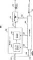
図1は、本発明の一側面による、動き補償画像レートコンバータ(MCPRC)回路100の高レベル図である。入力信号102は、ビデオフレームの離散シーケンスを有しており、MCPRC回路100に入力され、MCPRC回路は、アップコンバートされ動き補償された出力信号128を、MCPRC回路100のモジュール104、108、112、および116を介して生成する。MCPRC回路100の各モジュールを以下で説明する。アップコンバートの後、MCPRC回路100からの出力信号128は入力信号102のフレームレートより典型的に非常に高いフレームレートを有する。例えば、入力ビデオ信号102は、60Hzの画像レートを有するビデオカメラから生成されてよい。ビデオ信号は、例えば120Hzのリフレッシュレートを有するLCDパネルディスプレイ上の出力に適した形にすべく、MCPRC回路100を利用してアップコンバートされる必要がありうる。一般的には、フレームレートのアップコンバートは、所定の数の固有フレームを時間的に隣接した入力フレームの各対間に注入することで達成される。これらの介在フレームは、フレーム間のオブジェクトの動作軌跡を実質的に捉えるように作成されてよく、これによりアップコンバートの後でディスプレイされる際のビデオ画像シーケンス全体の滑らかさを高める。 FIG. 1 is a high level diagram of a motion compensated image rate converter (MCPRC)
図1を参照すると、入力信号102は先ずフロントエンドモジュール104でダウンコンバートおよび復調処理を受ける。このフロントエンドモジュール104は、チューナ、デモジュレータ、コンバータ、コーデック、アナログビデオデコーダ等の部材を含みうる。フロントエンドモジュール104からの出力106は、その後、下流のノイズ低減およびデインターレースモジュール108へ渡され、そこでは、信号106を、本来のインタレース走査に基づく形式から、高品質な順次走査出力110へ変換し、且つ、ブロックノイズおよびモスキートノイズなどのアナログノイズおよび補償アーチファクトを大幅に低減させる。結果生じる順次走査出力110は動き補償されたフレームレート変換(MCFRC)モジュール112へ供給され、そこでは動き補償され補間されたフレームを生成してビデオ出力シーケンス114が生成される。ビデオ出力シーケンス114は、元々の入力信号102の本来のフレームレートより高いフレームレートを有してよい。MCFRCモジュール112の動作の詳細を以下で詳述する。アップコンバートされたビデオ出力114は、その後、後処理モジュール116により処理され、典型的にデジタルビデオパイプラインに存在するスケーリング、エッジ強さ、色管理、画像制御などの追加的な強化機能がビデオ信号114に授受される。 Referring to FIG. 1, the
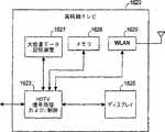
幾らかの実施形態においては、図1に示す全MCPRCアーキテクチャが単一のチップ上に実装されてもよい。一つの例示的構造においては、このMCPRCチップはテレビ回路に組み込まれてもよく、テレビ回路から、MCPRCチップのアップコンバートおよび後処理された出力128が外部のビデオディスプレイパネルへ送信される。しかし、後処理モジュール116が処理パイプラインから切り離され、その代わりにディスプレイパネルに組み込まれている場合、MCPRCシステム100の利用性が厳しく制限されることになる。これは、チップからLCDディスプレイに送信される際、信号114が入力信号102の本来のフレームレートより非常に高い帯域幅を占めるからである。多くの場合、テレビ回路がLCDディスプレイと通信できるような、整合高帯域幅インタフェースを見つけることはできない。しかし、MCPRCアーキテクチャ100を単一チップにカプセル化すると、システム100の様々な部材間で情報交換が促進されるという利点がある。 In some embodiments, the entire MCPRC architecture shown in FIG. 1 may be implemented on a single chip. In one exemplary structure, the MCPRC chip may be incorporated into a television circuit from which the MCPRC chip upconverted and post-processed output 128 is transmitted to an external video display panel. However, if the
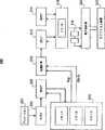
図2は、別のMCPRC構成200の高レベル図であり、図1のMCFRCブロック112および後処理モジュール116の順序を入れ替えて、ビデオを図2のMCFRCモジュール212で高い帯域幅にアップコンバートする処理よりも、後処理モジュール216の処理のほうを前に行う。アップコンバート機能を処理パイプラインの最後の段階に配置することで、アップコンバート機能が残りの回路と隔離されうる。故に、この配置により、モジュール204、208、および216をMCFRCモジュール212から切り離すことができる。幾らかの実施形態においては、モジュール204、208、216、および212は、図1のそれぞれ対応するモジュール104、108、116、および112と構造的に類似している。一例示的アーキテクチャにおいては、モジュール204、208、および216を組み込むチップが、テレビ受信回路に集積されて、入力信号202の本来のフレームレートで動作してよく、一方でMCFRCモジュール212が、他の処理部から切り離されたLCDディスプレイパネル内に集積されてもよい。この配置においては、テレビ回路からLCDディスプレイパネルへの送信信号214は、LCDパネルディプレイが要するアップコンバート帯域幅より比較的低い本来の帯域幅を占める。テレビ受信回路はLCDディスプレイと、低電圧差動信号(LVDS)チャネルなどの標準的なビデオ/ディスプレイインタフェースを介して通信する機能を有してよい。この低帯域幅のインタフェースにより、システム200の用途は広がり、任意の数の異なるディスプレイパネルをテレビ受信回路に接続することが可能となる。 FIG. 2 is a high-level diagram of another
図1、2に示すビデオ情報信号経路118および218はそれぞれ、対応するMCPRCシステム100および200のモジュール間の情報伝達を促進すべく提供されている。特に、MCFRCモジュール112および212に伝達される情報は、例えば、クローズドキャプションディプレイの位置、画面上の表示の存在、各入力信号102および202の本来のフレームレート、および各入力信号102および202の起点およびアクティブビデオ境界を含む。 The video
図示されているMCPRCシステム100および200では、入力ビデオ信号102および202は、標準精細(NTSC/PAL/SECAM)から高精細に亘っており、インタレース型でも順次型でもよい。幾らかの例においては、ビデオ信号解像度は、低フレームレートを有する標準解像度よりもさらに低い。例えば、入力ビデオ信号は、iPODなどの携帯型メディアプレーヤ内のコネクタデバイスから、毎秒15または30フレーム入力されるQVGA(320×240)であってよい。幾らかの例においては、低解像度ビデオ信号がパーソナルメディアプレーヤまたはマルチメディア携帯電話機のビデオドックにコネクタデバイスを介して供給されてよく、ここでドックには、例えば5fpsで320×160から60fpsで720×480の空間・時間変換(spatial and temporal conversion)を行う機能を有する集積回路が含まれうる。インタフェース入力は、ビデオに起因する(video‐originated)、またはフィルムに起因する(film‐originated)材料から形成されてよい。ビデオに起因する材料は、先ずデインタレースされて、フィールドレートからフレームレートへ変換されてからMCFRCモジュール112および212に入力される。フィルムに起因する材料は、MCFRCモジュール112および212への入力用に、本来の順次型形式に変換される。 In the illustrated
図3は、オブジェクト動き推定を入力ビデオ信号302の連続フレーム対の間に行うことを目的とする、図1および2のMCFRCモジュール112および212それぞれの例示的実装例300を示す。連続フレームの各対は補間されてよく、2つのフレームのうち前のほうは、「参照フレーム」と称され、後のほうは「現在のフレーム」と称される。図3のMCFRCモジュール300の例示的実施形態によると、動き推定エンジン306による動き補償および動き補償補間モジュール310による動き補間の前処理として、入力信号302はMCRFC制御部304で処理される。特に、動き推定エンジン306は、MCFRC制御部304からリンク322および324を介して送信された処理済フレーム情報を利用して、グローバルおよびローカル動き補償情報を入力シーケンス302の連続フレーム対各々に生成する。結果生じるグローバルおよびローカル動き補償情報は、今度は動き補償補間モジュール310へリンク308を介して転送され、また、MCFRC制御部304へもリンク322および324を介して転送される。幾らかの例においては、動き補償補間を行うという判断も、ビデオ入力信号302と、ビデオ情報信号316を介して得た入力の任意の追加的ビデオ情報とともに、制御部304から動き補償補間モジュール310に送られてよい。MCFRC制御部304および動き推定エンジン306から取得したデータに基づいて、動き補償補間を動き補償補間モジュール310で行うことで、望ましいフレームレートのビデオ画像シーケンスを生成するが、ここでシーケンスには、元々のビデオフレームシーケンスの間に時間的に散在した補間されたフレームが含まれている。幾らかの例においては、MCFRC制御部304は制御信号を、リンク326を介して動き補償補間モジュール310へ送ることで、ビデオ信号の一部の補間を不要としてよい。さらに、動き推定エンジン306からのビデオフレーム情報、ビデオ情報信号316、およびビデオ入力302も、出力314を介して他の処理ブロックへ転送されてさらなる処理を受けてよい。動き推定エンジン306、動き補償補間モジュール310、およびMCFRC制御部304の動作を、以下で詳述する。 FIG. 3 shows an
図3のMCFRC制御部304は、動き予測および後続のビデオ補間の品質に影響しうるある種のフレームフィーチャを削除しようと試みることで、入力ビデオ信号302の各フレームを処理する。この信号処理は、「真の」画像のみがグローバル動き推定の基として利用されるべきグローバルアフィン動き推定機能モジュール318において特に重要である。例えば、入力ビデオ信号302が、郵便ポスト(pillar box)およびサブタイトルなどのフィーチャを含むDVDである場合、MCFRC制御部304は、フレームを動き推定エンジン306に送る前に、各DVDフレームからピラーボックスを削除し、且つ、サブタイトルがフレームと融合している領域を特定することが望ましい。入力信号302が放送ビデオ信号である場合、MCFRC制御部304は、各ビデオフレームに関連付けられた静的チャネルロゴおよびティッカシンボルを特定することが望ましいが、このティッカシンボルとは、フレームの残りのシーンとはしばしば完全に反対方向に一定の速度で回転するものである。処理されたフレームシーケンスは、その後、リンク322および324を介して動き推定エンジン306へ転送されて、ローカルおよびグローバル動き推定がなされる。 The
別の実施形態においては、入力ビデオ信号302および入力ビデオ信号302に関する追加的情報が、入力316および330をそれぞれ介してMCFRC制御部304へ送信される。特に、ビデオ情報信号316は、例えばビデオに追加されるべき合成情報または動きベクトルの推定精度に影響するようなビデオの起点情報などの、入力ビデオ信号302に関する追加的情報を提供する。例えば、入力信号がコンピュータグラフィック信号であることが既知である場合、該信号は、ビデオに起因する信号と比して、水平方向、垂直方向両方に非常に鋭い遷移を持つ可能性が高い。グラフィックに起因するビデオ入力に関する動きベクトルは典型的に、ひとたびこの情報が動き推定エンジン306に提供されると、より正確に推定できる。しかし、ビデオ起点が動き推定エンジン306に提供されない場合、結果生じる動きベクトルの予測は不正確となってしまう。 In another embodiment, the
また別の実施形態によると、「シーンカット」検知回路を提供して、ビデオ信号内の特定のフレームについては動き補償補間モジュール310をディセーブルにすべきか否かを判断してよい。動き補償補間システムを利用することで、シーンが変更される間正確な動き推定を行うことが可能となる。故に、結果生じるアップコンバートされたビデオシーケンス内でこれら悪影響で大きい場合にはいつでも、入力信号302の動き補償補間を停止することができる。この一時的に補間を停止する判断は、動き推定エンジン306からリンク322および324を介して受信されたグローバルおよびローカル動き情報の分析に基づいてMCFRC制御部304で行われうる。MCFRC制御部304は、通信リンク326を介して動き補償補間モジュール310をイネーブルにもディセーブルにもできる。補間するという判断がなされると、MCFRC制御部304は、チャネル330から入力ビデオ信号302を、チャネル316からオプションのビデオ情報信号を、リンク322からグローバル動き信号を、およびリンク324からローカル動き信号を、動き補償補間モジュール310へ転送して、動き補償補間に備える。さもなくば、情報は出力314を介して後続の段に選択的に転送される。MCFRC制御部304では任意の他の基準を利用して動き補償補間をイネーブルおよびディセーブルにしてもよいことに留意されたい。 According to yet another embodiment, a “scene cut” detection circuit may be provided to determine whether the motion
図4は、図3の動き推定エンジン306のグローバルアフィン動き推定モジュール318の例示的実装例400である。グローバルアフィン動きとは、一般的には、一般にカメラのズーミング、パニング、あるいは回転などの動きが引き起こす、ビデオシーケンスの背景のピクセルの動きのことを言う。幾らかの実装例においては、ビデオフレームシーケンスの背景のピクセルは、全て単一の共通グローバル動きを受けると仮定される。グローバルアフィン動き推定は、通常、背景の動きを幾らかの基本パラメータを利用してモデル化する。特に、アフィンモデルは、6つのアフィンパラメータのみを利用して、任意のフレーム対間のグローバル動き軌跡を表す。アフィンパラメータのうち2つは、カメラのズーミング動きを捉えるのに利用されるスケーリングパラメータであり、2つは回転パラメータであり、2つはパニング動きを捉えるのに利用される並進パラメータである。これら6つのアフィンパラメータは、グローバル動き予測の上で非常な柔軟性を提供する。 FIG. 4 is an
図4に示すように、グローバルアフィン動き推定モジュール400は2段の処理であり、第1段402が、任意のフレーム対間のグローバル動きを粗い解像度で捉えるのに利用されるアフィンパラメータ一式の粗い推定を行う。より具体的には、第1段は、位相相関法を利用してグローバル並進動きに関する2つのアフィン並進パラメータを推定するが、これは図5‐7との関連で詳述する。第1段はさらに、グローバルな回転およびスケーリング動きに関する、残りの4つのアフィンパラメータを予測する。これら予測は、前のフレーム対など、過去に行った推定から算出した対応アフィン値に基づいている。結果生じるアフィンパラメータを今度は第2段406に渡し、より高精細な解像度レベルにまでリファインする。 As shown in FIG. 4, the global affine
特に、図4の実施形態によると、フレームシーケンスを有するアクティブビデオ入力信号404を、グローバルアフィン動き推定モジュール400の段402に供給する。幾らかの実施形態においては、サブタイトル、OSDメニューなど全ての重要でないビデオ情報を、グローバルアフィン動き推定モジュール400へ供給する前のアクティブビデオ入力信号404から除去する。段402においては、グローバル並進またはパニング動きに関する、2つのアフィン並進パラメータのみを推定する。グローバル並進動きを隔離する理由は、カメラの動きはその性質上圧倒的に並進的な動きであり、典型的に大きな並進範囲を捉えるのが難しいからである。殆どの市販の動き推定ツールは、非常に制限的な計測範囲を有しており、動きが許容範囲外である場合にはしばしば不正確な動き計測値を生成するきらいがある。これと比較すると、本発明のグローバル並進推定技術によれば、入力フレームの1画像サイズの半分の並進動き範囲まで正確に計測することができる。このグローバル並進推定は、粗い表示フレームの各対に対して適用した位相相関法を利用して達成される。位相相関法は図5との関連で詳述する。2つの粗い予測アフィン並進パラメータを含む粗い並進推測値数1がモジュール402により提供される。さらに、2つのアフィン回転パラメータと2つのアフィンスケーリングパラメータとを含む4つの残りのアフィンパラメータの粗い推定値である数2が、前のフレームのこれらパラメータの過去の推定値に基づいて計算される。
これら粗いレベルのアフィンパラメー推定値数1および数2はその後、RANSAC(RANdom SAmple Consensus)に基づくアフィンパラメータリファインモジュール406へ送信され、さらにリファインされる。このリファインは、先ず、段402からの粗く予測されたアフィンパラメータを利用して参照フレームの画像を動き補償することで達成される。故に、補償された参照フレームと現在のフレームとの間の差は、補償された参照フレーム画像を現在のフレーム画像に実質的に位置合わせするのに必要な、粗く予測されたアフィンパラメータの調節量である。一実施形態においては、RANSACに基づく技術を利用してこのようなリファインを達成する。このRANSACに基づく方法406は先ず、その最も精細な解像度で表される現在のフレームから、所定の数のランダムに配置されたピクセルブロックを選択することで動作する。これらブロックも、補償された参照フレーム内に対応するブロックを有する。次にセグメンテーションマスクを動き補償された現在のフレームに適用して、フレーム画像の前景領域および背景領域を区別する。フレームの背景領域に属するブロックのみを利用して、グローバル動き予測に関するアフィンパラメータをリファインする。こうする理由は、背景のピクセルの動きだけが、アフィンパラメータにより概算されるグローバル動きに曝されると仮定されるからである。リファインされた並進推定値A<SUB>i</SUB>および予測推定値であるB<SUB>i</SUB>はその結果アフィンパラメータリファイン段406で生成される。セグメンテーションマスク算出を以下に詳述する。 These coarse level affine parameter estimates
図5は、位相相関法の例示的ブロック図実装500を示す。位相相関法は、図4のグローバル並進推定および予測段402に実装されて、2つの連続フレーム間のグローバル並進動きに関するアフィンパラメータの粗いレベルの予測を行う。位相相関は、どちらもフーリエ領域で表される並進画像とその参照画像との間に位相差のみが存在するようなフーリエシフト特性を利用することで、この並進動きを計測する。さらには、この位相差の指数の逆フーリエ変換により、相関面が形成され、ここから2つの画像フレーム間の並進動きの計測値が得られる。この動作を表す例を以下で説明する。 FIG. 5 shows an exemplary
標準解像度のテレビ画像のフーリエ変換は、殆どの用途において法外に高価になってしまうことが公知である。この動作の複雑性を低減すべく、参照フレームと現在のフレームとを、これら画像がフーリエ変換前に所定のファクタによりダウンサンプリングされた、粗い解像度レベルで表す。このダウンサンプリングは、図5に示す、水平方向および垂直方向両方で各画像をデシメーションするデシメーションモジュール502を介して達成される。一実施形態においては、画像のデシメーションは多相を分離可能なフィルタ法を利用して達成される。結果生じるデシメーションされた画像フレームが、垂直方向および水平方向両方で各々高速フーリエ変換(FFT)される。2DのFFTは、2つの連続する1DのFFTを行うことで達成され、デシメーションされた画像は典型的に、列方向のFFTをモジュール506により受ける前に行方向のFFTをモジュール504により受ける。参照フレームおよび現在のフレームに対応するFFT結果は各々2Dの複素数データアレイで表され、一時的なデータ記憶用にメモリ508に配置される。続いて、2D位相差アレイが、2つの複素数データアレイから生成される。次に、位相差アレイのエレメントについての指数(element-wise exponential)をとって、1Dの列IFFT514の後に1D行IFFT512により2D逆高速フーリエ変換(IFFT)された行列を生成する。これら列514および行512のIFFT中に、メモリブロック516を一時的なデータ記憶用に利用してもよい。このような2DのIFFTから、2Dデータアレイでも表される正規化相関面を次に出力518に生成して、最大計算モジュール520に供給する。最大計算モジュール520は、相関面アレイの最大の値および位置、且つ最大値に隣接する値の幾らかを決定することで動作する。最後に、サブピクセル補間モジュール522を利用して、最大値およびそれに隣接する値を補間して、グローバル並進推定値を生成する。2DのFFTの詳細および位相差計算を以下で説明する。 It is known that Fourier transforms of standard resolution television images become prohibitively expensive for most applications. To reduce the complexity of this operation, the reference frame and the current frame are represented at a coarse resolution level where the images are downsampled by a predetermined factor prior to Fourier transform. This downsampling is accomplished via a
図5の各フーリエ変換の出力は複素数の2Dアレイである。結果生じる動き推定の精度には有限精度計算による数量化効果が直接関与するので、各複素数の浮動小数点を記憶するのに必要となりうるビット数は注意深く考慮されねばならない。一実施形態においては、192ビットの浮動小数点FFTをモジュール504で利用して、行FFTを実装し、128ビットの浮動小数点FFTをモジュール506で利用して、列FFTを実装する。図6は、例示的な256×256ビットの2DのFFT設計600を示す。設計600の各工程で利用される例示的なビット精度も提供される。行FFT実装は実質的に列FFTと同一でありえるが、1DのFFTにより1方向に変換された後の入力フレームは転置され(90度回転される)、同様に、同じ1DのFFTを利用して第2の方向に変換される。2DのFFTも、2つの実質的に同一な1DのIFFTを利用して同様に実装されうる。 The output of each Fourier transform in FIG. 5 is a complex 2D array. Since the resulting motion estimation accuracy is directly related to the quantification effect of finite precision calculations, the number of bits that may be required to store the floating point of each complex number must be carefully considered. In one embodiment, a 192-bit floating point FFT is used in
図7は、図5の位相差計算モジュール510の例示的ブロック図700である。2つの複素数データアレイ内の対応するエレメントから得られた複素数の値の対を、例示的な位相差計算モジュール700へ入力702および710として供給する。図7に示す一実施形態においては、入力702および710がそれぞれ、フーリエ領域のデシメーションされた参照画像フレームおよび現在の画像フレームを表す二つの複素数データアレイから取られる。入力702および710の実数部分および虚数部分を分離して分ける。複素数入力702および710と関連する位相を、入力信号の虚数部分および複素数部分の商から、アークタンルックアップテーブル706および714それぞれを用いて、処理704および712で得られた商の大きさにそれぞれ基づいて、決定する。直交補正モジュール708および716でリファインされた後、二相は加算器718で互いから減算され、位相差718が生成される。同様に、この処理を、現在のFFTデータアレイおよび参照FFTデータアレイの対応するエレメントの全ての対に対して行って、位相差の2Dアレイを生成してよい。 FIG. 7 is an exemplary block diagram 700 of the phase
図5‐7の例示的実装例によるグローバル動き推定を行った後で、アフィン動き値をグローバル動き補償の適切なピクセルに対して割り当ててよい。フレームの前景に属するピクセルは、例えばセグメンテーションマスクなどの利用により、背景に属するものと区別される必要がある。背景に属するピクセルは、前述の6つのアフィンパラメータで概算される単一のグローバル動きを受けることが仮定されてよい。これに対して前景のピクセルは、同じグローバル動きでは動かない。このようなピクセルに対しては、適切なローカル動きベクトルまたは補正グローバル動きベクトルを決定してよい。 After performing global motion estimation according to the example implementation of FIGS. 5-7, affine motion values may be assigned to appropriate pixels for global motion compensation. Pixels belonging to the foreground of the frame need to be distinguished from those belonging to the background, for example by using a segmentation mask. It may be assumed that the pixels belonging to the background undergo a single global motion that is approximated by the six affine parameters described above. In contrast, foreground pixels do not move with the same global movement. For such pixels, an appropriate local motion vector or corrected global motion vector may be determined.
図8は、セグメンテーションマスクの最初の版を計算する例示的方法を示す。例示により、グローバル補償フレーム802および本来のフレーム804がシステム800への入力として供給される。そして、ピクセル毎の、2つの入力フレーム間の絶対値の差を、加算器処理805および絶対値処理806で計算する。結果生じるピクセル毎の絶対値の差のアレイを、合算・比較モジュール808に供給して、絶対値の差をピクセルブロック毎に加算して、閾値807と比較する。絶対値のブロック合算値が閾値より大きい場合にピクセルブロック全体がフレームの前景に属すものとして分類されうる。さもなくば、ブロックはフレームの背景に属すものとして分類されうる。モジュール808はフレーム内に各ピクセルブロックの単一のビットバイナリ出力を生成して、この情報を提供し、これら出力の集合体が、潜在的にフレーム内の前景ブロックと背景ブロックとを区別するセグメンテーションマップ809を形成する。ノイズおよび隔離動き領域の存在により、セグメンテーションマップ809は誤って分類されたブロック領域を含みうる。故に、セグメンテーションマップ809は、拡張(dilation)812の後の閉路(closing)810などのバイナリ形態素処理を受け、より同質な最初のセグメンテーションマスク814を生成する。 FIG. 8 shows an exemplary method for calculating the first version of the segmentation mask. By way of example, a
図9は、図8の処理から得た最初のセグメンテーションマスク902に基づき最終のセグメンテーションマスクを計算する例示的方法900を示す。セグメンテーションマスク902は、適切な補償法を画像フレームの個々のピクセルに適用しうるマップを提供する。システム900は、最初のセグメンテーションマスク902から様々な接続されたオブジェクトを検出することで動作し、ここからピクセルが再分類されて特定の補正処置を受けてよい。一実施形態においては、接続された部材分析904をモジュール904で利用して、接続されたオブジェクトを特定する。特に、二つのオブジェクトを幾らかのピクセルのみで分離した場合、小さなオブジェクトを大きなオブジェクトの一部としてみることができる。図9の実施形態においては、2×2の解像度ブロックサイズが接続された部材分析で利用されて、オブジェクト接続特定のコスト全体を低減する。しかし、他の解像度サイズも可能である(例えば3×3、4×4)。接続部材分析の最後には、モジュール904は最初のセグメンテーションマスク902から全ての接続オブジェクトを特定するラベルリストを出力するが、ラベルリストにおいて各オブジェクトはフレーム内の該オブジェクトの位置を特定するインデックスに対応している。インデックスおよびラベルのリストは、オブジェクトごとのエッジブロックの数を計算するモジュール906に供給される。オブジェクト内のブロック数を所定の閾値912と比較することで、オブジェクトが小さいと判断される場合、オブジェクトのブロックを、画像フレームの背景に属すものとして分類する。これら背景ブロックは、上述のグローバルアフィン動き推定パラメータを利用して補償されてよい。しかし、1つのオブジェクトに関するブロック数が多い場合、これらブロックは画像フレームの前景に属すものとして分類されることがあり、グローバル動き補償法よりも正確でありうるローカル動き補正法を施される。 FIG. 9 illustrates an
本発明の別の側面によると、入力フレームについてオブジェクトエッジマップのロバストな生成手順を提供して、該フレーム内で大きなエッジ強さ(significant edge strength)を有するオブジェクトを特定することができる。オブジェクトに関するエッジ強さの欠如は、該オブジェクトとその直ぐ周辺との間にコントラストが弱いことを示す。故に、該オブジェクトがたとえセグメンテーションマスクが示すよう入力フレームの前景に存在したとしても、該オブジェクトのピクセルに対してはグローバル動き補償を適用してよい。これは、より正確な補償法を、エッジ強さが小さいオブジェクトに適用することで生じる結果が、グローバル動き補償法を適用することで生じるものと同一である可能性が高く、且つ、グローバル動き補償法が二つの方法のよりコスト効率のよい可能性が高いからである。故に、計算効率のためには、ロバストなオブジェクトエッジマップ生成法を提供して、エッジが強いオブジェクトを検知してよい。この方法によると、任意の画像フレーム内のピクセルブロック全てについて、2つの固有値が生成され、該固有値はそれぞれブロックの水平方向の計測値および垂直方向の計測値に対応する。例えば、SDTV解像度標準を2×2のブロックサイズについて利用すると仮定すると、各SDTV画像フレームについて、全部で360個のブロックが水平方向に、且つ288個のブロックが垂直方向に生成されることになる。全ての固有値の最大値(ev_max)をその後決定する。固有値が、最大値により計測される所定の範囲にあるこれらブロックは、例えば、範囲「0.8*ev_max,ev*max」内にあり、大きなエッジ強さを有するものとして特定されてよく、故に、グローバル動き補正法よりもより厳密な動き補償を要する可能性が高い。これらブロックは値1を割り当てられ、値0を割り当てられうる残りのブロックから区別されてよい。この結果、1のブロックが1画像フレーム内の大きなエッジ強さを有するオブジェクトを明示するようなオブジェクトエッジマップが生成される。さらには、1および0のブロックの利用により、このオブジェクトエッジマップ自身がかなりノイズに対して強くなる。本実施形態では2×2のブロックサイズを利用したが、任意の他のブロックサイズを利用することもできる(例えば4×4)。 According to another aspect of the present invention, a robust object edge map generation procedure can be provided for an input frame to identify objects having significant edge strength within the frame. The lack of edge strength for an object indicates a weak contrast between the object and its immediate surroundings. Thus, even if the object is in the foreground of the input frame as indicated by the segmentation mask, global motion compensation may be applied to the object's pixels. This is because the result of applying a more accurate compensation method to an object with low edge strength is likely to be the same as the result of applying the global motion compensation method, and global motion compensation. This is because the method is likely to be more cost effective than the two methods. Thus, for computational efficiency, a robust object edge map generation method may be provided to detect objects with strong edges. According to this method, two eigenvalues are generated for every pixel block in an arbitrary image frame, and the eigenvalues correspond to the horizontal and vertical measurements of the block, respectively. For example, assuming that the SDTV resolution standard is utilized for a 2 × 2 block size, a total of 360 blocks will be generated horizontally and 288 blocks vertically for each SDTV image frame. . The maximum value (ev_max) of all eigenvalues is then determined. Those blocks whose eigenvalues are in a predetermined range measured by the maximum value may be identified, for example, as being within the range “0.8 * ev_max, ev * max” and having a large edge strength. There is a high possibility that stricter motion compensation is required than the global motion compensation method. These blocks are assigned the
図10は、入力フレーム1002内の各ピクセルブロックに関する固有値の対を計算する処理1000を示す。各固有値は、そのブロックの垂直方向および水平方向の計測値に対応しており、ルマ(luma)または強度領域で表されるそのブロックのピクセル値から計算される。5×5のブロックサイズの利用を仮定すると、フレーム1002のピクセル強度は、先ず5×5のウィンドウサイズを有する2次元ガウスフィルタ1004でフィルタにかけられる。ガウスフィルタ1004にかける主な目的は、ノイズを平滑化して、各ブロック内の小さなオブジェクトを隔離して、それらを固有値算出の候補から除くことにある。これは、大きなエッジ強さを有する大きなオブジェクトのみに対してこのより厳密な補償処置を行うほうがコスト効率がよいからである。ブロックサイズが5×5であるガウスフィルタについては、各々がサイズ720×8ビットである4つのラインバッファを利用してこのようなフィルタサイズをサポートしてよい。これらラインバッファはSRAM内に実装できる。別の実施形態においては、ガウスフィルタ1004は、シリコン領域の利用を最小限にとどめるべく、より小さなブロックサイズ(例えば3×3)を利用してもよい。この結果、ラインバッファハードウェアのサイズが、5×5のブロックサイズに比較して、50%低減できる。 FIG. 10 shows a
ガウスフィルタ1004でフィルタされた2Dの強度値アレイ1005は、アレイ1005の強度値の勾配を推定すべく、勾配処理モジュール1006に供給される。一実施形態において、勾配は、アレイ1005の隣接する強度値間の一次差(first order difference)を求めることに基づいて、水平方向および垂直方向両方において、計算される。この一次差計算は、ブロック毎に行われてよい。例えば、2×2のブロックのデータアレイ1005を例にとって考えるが、みて分かるように、この例では、ブロックがA、B、D、およびEという強度値からなり、強度CおよびFが右側で隣接しており、GおよびHが底側で隣接している。
2次元平均値計算モジュール1020は、ブロック毎に、各入力アレイ1014、1016、および1018の2乗勾配値を平均化して、アレイのブロック毎にスカラー平均値を生成することで動作する。例えば、2×2ブロックサイズを利用する場合、各ブロックの4つの勾配値が平均化されて、単一のスカラー値を生じる。この結果、数6で表される平均2乗勾配値の3つの2Dアレイ1022、1024、および1026がモジュール1020から生成される。
図11は、図10の固有値計算モジュール1030の例示的実装1100を示す。示されているように、数7のアレイは数8のアレイから加算器1102で減算され、差行列Rを生成する。この差行列は、その後、処理1104でエレメントごとに2乗されて、数9のアレイがエレメントごとの2乗処理1108および4つの乗算のファクタを受けた後で、数9のアレイに加算器1106で加算される。
図10および11に示す実施形態においては、2×2のブロックサイズを固有値の計算に利用した。しかし、これより大きなブロックサイズを利用してハードウェア利用を低減することもできる。さらには、より小さなブロックサイズを利用することで推定の精度を上げることもできる。さらには、各固有値が正、小数点、および0から1の間で変化することから、8ビット精度を利用して固有値を表すことで、数値の観点からは十分な精度が得られることがある。しかし、他の精度値を利用することもできる。 In the embodiment shown in FIGS. 10 and 11, a 2 × 2 block size was used for eigenvalue calculation. However, hardware utilization can be reduced by using a larger block size. Furthermore, estimation accuracy can be improved by using a smaller block size. Furthermore, since each eigenvalue varies between positive, decimal point, and 0 to 1, sufficient accuracy may be obtained from a numerical point of view by representing the eigenvalue using 8-bit accuracy. However, other accuracy values can be used.
まとめると、セグメンテーションマスク計算処理を、図8および9に関して記載した。結果生じるセグメンテーションマスクを利用して、画像フレームの前景および背景に属すオブジェクトを特定することができる。加えて、図10および11に関して、オブジェクトエッジマップ生成処理を上述した。これにより得られるオブジェクトエッジマップを利用すると、大きなエッジ強さを有するフレームのオブジェクトを隔離することができる。セグメンテーションマスクおよびオブジェクトエッジマップの組み合わせにより、動き推定精度および効率性両方を最大化するような、画像フレームのサブ領域への適用に適した補正技術を決定することができる。概して、1フレーム内の各ピクセルブロックは、該ブロックの前景/背景分類およびそれらが示すエッジ強さに基づいて、3つの種類の動き補償のいずれかを経る。これら3つの種類とは、グローバル動き補償、補正グローバル動き補償、およびローカル動き補償である。前景の各ブロックは、図9で生成されたもののようなセグメンテーションマスクにより特定され、画像フレームのオブジェクトエッジマップが決定するローカル動き補償または補正グローバル動き補償を施される。フレームの背景のブロックも、セグメンテーションマスクによる特定が可能であり、図4‐7の処理で得られたグローバルアフィンパラメータを利用してグローバル動き補償を施される。この補償法種別選択処理およびローカルおよび補正グローバル動き補償法を以下で詳述する。 In summary, the segmentation mask calculation process has been described with respect to FIGS. The resulting segmentation mask can be used to identify objects belonging to the foreground and background of the image frame. In addition, the object edge map generation process has been described above with respect to FIGS. By using the object edge map obtained in this way, it is possible to isolate an object of a frame having a large edge strength. The combination of segmentation mask and object edge map can determine a correction technique suitable for application to sub-regions of an image frame that maximizes both motion estimation accuracy and efficiency. In general, each pixel block within a frame undergoes one of three types of motion compensation, based on the foreground / background classification of the block and the edge strength they indicate. These three types are global motion compensation, corrected global motion compensation, and local motion compensation. Each foreground block is identified by a segmentation mask such as that generated in FIG. 9 and is subjected to local motion compensation or corrected global motion compensation as determined by the object edge map of the image frame. The background block of the frame can also be specified by the segmentation mask, and global motion compensation is performed using the global affine parameters obtained by the processing of FIGS. 4-7. This compensation method type selection processing and local and corrected global motion compensation methods will be described in detail below.
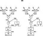
図12は、2つのピクセルブロック間の動きを捉えるローカル動きベクトルの導出に利用される技術の例示的実施形態を示しており、ここで1つのブロックは参照フレーム内にあり、他のブロックは現在のフレーム内にある。ブロック対は、それらの隣接するブロックの動きに対する、自身の動きに基づいて検出されうる。例えば、動き検出は、相関するブロック対間の動きが、隣接するブロック間の均一なグローバル動きの方向とは異なる、という観察に基づいて行われてよい。図12に示された実施形態によると、3×3のブロック配置1200の中心のブロック1205を、ローカル動きベクトルを推定する現在のフレームの対象ブロックとして選択する。現在のフレーム処理の時間tにおいては、ブロック1205は4つの隣接するブロック1201‐1209を、それぞれブロック1205からみた北、東、南、および西に有する。さらに、現在のフレームは、現在のフレームの前の時間t‐1において処理される、時間的に隣接する参照フレームを有する。この参照フレームは、現在のフレームのブロック1201‐1209と1対1の関係にある一式のブロックを含む。現在のフレームのブロック1205の動きベクトルは、その後、前のフレームのブロック1201‐1204について時間t‐1に計算されたグローバル動きベクトルから概算することができる、というのも、中心のブロックの動きは、隣接するブロックのものと僅かにしかずれていないと仮定できるからである。時間t+1における後続のフレームでは、各ブロック1206‐1209の動きベクトルを、時間tに計算されたその北、南、西、および東に隣接するブロックの動きから推定する。故に、フレームシーケンスの動きの値は、隣接する値に基づいて、画像シーケンスのフレームがそれぞれ時間的に進むにつれて、連続的にリファイン(refine)されていくことになる。 FIG. 12 illustrates an exemplary embodiment of a technique used to derive a local motion vector that captures motion between two pixel blocks, where one block is in a reference frame and the other blocks are currently In the frame. Block pairs can be detected based on their motion relative to the motion of their neighboring blocks. For example, motion detection may be based on the observation that the motion between correlated block pairs is different from the direction of uniform global motion between adjacent blocks. According to the embodiment shown in FIG. 12, the
図12も、本発明の別の側面による補正グローバル動き補償法を示すのに利用される。この補正グローバル動き補償法は、グローバル動き補償が、ブロックの動きを推定するには十分な精度を持たない場合に利用される可能性が高い。故に、グローバルアフィンパラメータに小さな補正を行って、生じる精度を向上させねばならない。また図12の実施形態を参照すると、3×3のブロック配置1200の中心のブロック1205を、ブロック1205からそれぞれ北、東、南、および西に位置する4つの隣接するブロック1201‐1209を有する現在のフレーム上の対象ブロックとして選択する。補正グローバル動き補償を決定した現在のフレームのグローバル動き補償版を決定しうる。このグローバル動き補償された現在のフレームは、現在のフレームのブロック1201‐1209と1対1の関係にある一式のブロックを含む。現在のフレーム内のブロック1205の動きベクトルは、その後、対応するグローバル動き補償されたフレームのブロック1201‐1204のグローバル動きベクトルから推定されてよい。特に、ブロック1205は、グローバル動き補償フレーム上の隣り合うブロック1201‐1204各々について計算された単一の均一な動きベクトルから全ての方向の増加量により並進または動きシフトされる。その結果生じる最も整合するベクトルが、ブロック1205の最終動きベクトルになる。この増加分は、XcおよびYcという補正パラメータ対で表されてよく、ここではXcが水平グローバル方向のスカラーシフトを表し、Ycが垂直グローバル方向のスカラーシフトを表す。 FIG. 12 is also used to illustrate a corrected global motion compensation method according to another aspect of the present invention. This corrected global motion compensation method is likely to be used when global motion compensation is not accurate enough to estimate the motion of a block. Therefore, a small correction must be made to the global affine parameters to improve the resulting accuracy. Referring also to the embodiment of FIG. 12, the
ある実施形態においては、ローカル動き推定法は、補正グローバル動き補償法と類似しているが、前者では、ブロック補償量が現在のフレームと参照フレームとの比較に基づき決定されるのに比して、後者ではこの量を現在のフレームと、現在のフレームのグローバル動き補償された版との比較に基づいて決定されることが異なる。幾らかの実装例においては、補償量は、対象ブロックから所定の範囲内(例えば、対象ブロックを囲む3ピクセルブロックの範囲内)にあるピクセルの動きベクトルに基づいて決定される。 In some embodiments, the local motion estimation method is similar to the corrected global motion compensation method, but in the former, compared to the block compensation amount being determined based on a comparison between the current frame and the reference frame. The latter differs in that this amount is determined based on a comparison of the current frame with a global motion compensated version of the current frame. In some implementations, the amount of compensation is determined based on motion vectors of pixels that are within a predetermined range from the target block (eg, within a range of 3 pixel blocks surrounding the target block).
ローカル動きベクトルおよび補正グローバル動きベクトルの計算に対して隣接検索アルゴリズムを利用することの決定的な利点は、対象ブロックについて限られた数の隣接ブロックのみを検索すればいい、ということにある。加えて、これら隣接ブロックを利用して導出およびリファインされる動き推定値は、既に前のフレームで計算済みである。故に、これら技法は、動き推定の効率を大幅に高める。 The decisive advantage of using the neighbor search algorithm for the calculation of the local motion vector and the corrected global motion vector is that only a limited number of neighboring blocks need be searched for the target block. In addition, the motion estimates derived and refined using these neighboring blocks have already been calculated in the previous frame. Hence, these techniques greatly increase the efficiency of motion estimation.
図13は、現在のフレームの各ブロックについてどの動き補償法を利用すべきかを選択する工程を示す。例えば、マルチプレクサ1310は先ず、グローバル動き補償法1312と、よりリファインされた補償法1314との間で選択を行う。この決定は、フレームの前景ブロックを背景ブロックから区別するセグメンテーションマスク1318の利用に基づいて行われる。グローバル動き補償1312は背景ブロックのみに適用される。任意のブロックがより精度の高い補正法を必要とする場合、マルチプレクサ1302は、ローカル動き補償法1304と補正グローバル動き補償法1306、いずれをそのブロックに適用するかの決定を行う。この決定は、そのブロックを補償するのに、ローカル動き補償法1304と補正グローバル動き補償法1306のいずれを利用するとエラーがより小さくなるか、を考えて行われる。故に、最終的なセグメンテーションマスク1318は、対象ブロック各々について適切な動き補償法を選択することができるので、グローバル、ローカル、または補正グローバル動きベクトル一式を各ブロックについて計算することができる。 FIG. 13 shows the process of selecting which motion compensation method to use for each block of the current frame. For example,
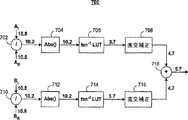
図14に示す本発明の別の側面によると、後処理手順1400を、図13の回路から取得したローカル動きベクトル1418をリファインするのに用いる。一般的なローカル動きベクトルは、ノイズおよびアパーチャー効果を受けやすい。故に、メジアンフィルタ1402および1404一式が、ローカルベクトル1418のx−ベクトル方向およびy−ベクトル方向両方に適用されて、ローカル補正に関する悪影響をいずれも最小限に抑える。メジアンフィルタの動作の前提は、隔離されたローカルブロックに隣接する全てのブロックが、隔離されたブロックの動きとは大幅に異なる均一な方向に動くとすると、隔離されたブロックの動きベクトルは、大部分の動きと実質的に適合するよう補正されねばならない、というものである。入力セグメンテーションマスク1406をメジアンフィルタ1402および1404とともに利用して、これら隔離されたブロックを特定する。メジアンフィルタの後に、x‐方向およびy‐方向両方のリファインされたローカル動きベクトル1408‐1410は、x‐方向およびy‐方向両方に、エッジ適合またはガウスフィルタ1412および1414一式によりさらなる処理を受ける。ガウスフィルタ1412および1414は、それぞれx−方向およびy−方向にローカル動きベクトル1408および1410を平滑化することで動作するが、ここで各ベクトル成分に適用される平滑化量は、図10および11で上述した手順を利用した入力オブジェクトエッジマップ1416により決定される。 According to another aspect of the invention shown in FIG. 14, a
本発明のまた別の側面においては、動き補償補間法を利用して、一対の入力参照フレームおよび現在のフレーム間の1以上の中間フレームを推定する。先ず、一対のフレーム間のオブジェクトの動きを、一式の動きベクトルによりブロック毎に特徴づける。動きベクトルはその後、1以上の中間フレームを補間するのに利用され、それらが順次フレーム間の動き軌跡を捉えるようにする。より具体的には、図15に示すように、モジュール1502を利用して、グローバル動き補償が必要な中間フレームの領域を補間する。この種類の動き補償補間は、一式の所定のグローバルアフィンパラメータ1504および参照フレーム1506と現在の入力フレーム1508の対とに基づいて計算される。モジュール1510を利用して、ローカル動き補償が必要な中間フレームの領域を補間する。この種類の動き補償補間は、一式の所定の入力ローカル動きベクトルおよび参照フレーム1506と現在の入力フレーム1508の対とに基づいて達成される。セグメンテーションマスク1514を利用して、1フレームの各領域が、補間中に、グローバルまたはローカルに動き補償されるべきかを決定してよい。 In yet another aspect of the invention, motion compensated interpolation is used to estimate a pair of input reference frames and one or more intermediate frames between the current frame. First, the motion of an object between a pair of frames is characterized for each block by a set of motion vectors. The motion vectors are then used to interpolate one or more intermediate frames so that they sequentially capture the motion trajectory between frames. More specifically, as shown in FIG. 15, a
以上示した実施形態は、例示的であり、本発明の範囲を制限するものではない。開示した通信システムの様々なブロックで実装できるとして記載した式は、ハードウェア回路および/またはプロセッサ上で動作するソフトウェア命令により計算することができる。式の計算は、式内の項や演算そのものではなくてもよい。例えば、式計算は、式計算の結果が略等しくなるような、他の項および演算を利用して行われてもよい。故に、通信システムの様々なブロックは、直接これら式を計算することなしに、式に基づいた計算を行うことで行われてもよい。 The embodiments described above are exemplary and do not limit the scope of the present invention. The equations described as being implemented in various blocks of the disclosed communication system can be calculated by software instructions running on hardware circuits and / or processors. The calculation of the expression may not be a term in the expression or the operation itself. For example, the formula calculation may be performed using other terms and operations such that the results of the formula calculation are approximately equal. Thus, various blocks of the communication system may be performed by performing calculations based on equations without directly calculating these equations.
図16A−16Eを参照すると、本発明の様々な例示的実装例が示されている。 Referring to FIGS. 16A-16E, various exemplary implementations of the present invention are shown.
図16Aを参照すると、本発明は、高精細テレビ(HDTV)1620に実装しうる。本発明は、HDTV1620の、一般的に図16Aでは1622として特定される処理および/または制御回路、WLANインタフェース1629、および/または大容量データ記憶装置1627を実装してよい。HDTV1620はHDTV入力信号を有線形式あるいは無線形式で受信して、ディスプレイ1626用にHDTV出力信号を生成する。幾らかの実施例においては、HDTV1620の信号処理回路および/または制御回路1622および/または他の回路(不図示)はデータ処理、符号化および/または暗号化、計算、データフォーマッティングおよび/またはHDTVが必要としうるその他の種類の処理を行いうる。 Referring to FIG. 16A, the present invention may be implemented in a high definition television (HDTV) 1620. The present invention may implement processing and / or control circuitry,
HDTV1620は、データを不揮発な形で記憶しうる大容量データ記憶装置1627と通信しうるが、ここで大容量データ記憶装置1627は、ハードディスクドライブ(HDD)および/またはデジタルバーサタイルディスク(DVD)ドライブなどの、光学記憶デバイスおよび/または磁気記憶デバイスを含みうる。HDDは、直径が約1.8"より小さい一以上のプラッタを含むミニHDDであってもよい。HDTV1620は、RAM、ROM、フラッシュメモリなどの低レイテンシー不揮発性メモリ、および/または他の適切な電子データ記憶装置などのメモリ1628に接続されうる。HDTV1620はWLANインタフェース1629を介したWLANへの接続を支援しうる。 The
図16Bを参照すると、本発明は、車両1600のデジタル娯楽システム1604に実装することができ、これは、WLANインタフェース1616および/または大容量データ記憶装置1610を含みうる。 Referring to FIG. 16B, the present invention may be implemented in a
デジタル娯楽システム1604は、データを不揮発な形で記憶しうる大容量データ記憶装置1610と通信しうる。大容量データ記憶装置1610は、ハードディスクドライブ(HDD)および/またはデジタルバーサタイルディスク(DVD)ドライブなどの、光学記憶デバイスおよび/または磁気記憶デバイスを含みうる。HDDは、直径が約1.8"より小さい一以上のプラッタを含むミニHDDであってもよい。デジタル娯楽システム1604は、RAM、ROM、フラッシュメモリなどの低レイテンシー不揮発性メモリ、および/または他の適切な電子データ記憶装置などのメモリ1614に接続されうる。デジタル娯楽システム1604はWLANインタフェース1616を介したWLANへの接続を支援しうる。
図16Cを参照すると、本発明は、携帯式アンテナ1651を含みうる携帯電話機1650に実装しうる。本発明は、携帯電話機1650の、一般的に図16Cでは1652として特定される処理および/または制御回路、WLANインタフェース1668、および/または大容量データ記憶装置1664を実装してよい。幾らかの実施例においては、携帯電話機1650は、マイクロフォン1656、スピーカおよび/または音声出力ジャックなどの音声出力1658、ディスプレイ1660、および/またはキーパッド、ポインティングデバイス、および/またはボイス駆動および/または他の入力デバイスなどの入力デバイス1662を含みうる。携帯電話機1650内の信号処理および/または制御回路1652および/または他の回路(不図示)は、データ処理、符号化および/または暗号化、計算、データフォーマッティングおよび/またはその他の携帯電話機能を行いうる。 Referring to FIG. 16C, the present invention can be implemented in a
携帯電話機1650は、データを不揮発な形で記憶する大容量データ記憶装置1664と通信しうるが、大容量データ記憶装置1664は、ハードディスクドライブ(HDD)および/またはデジタルバーサタイルディスク(DVD)ドライブなどの、光学記憶デバイスおよび/または磁気記憶デバイスを含みうる。HDDは、直径が約1.8"より小さい一以上のプラッタを含むミニHDDであってもよい。携帯電話機1650は、RAM、ROM、フラッシュメモリなどの低レイテンシー不揮発性メモリ、および/または他の適切な電子データ記憶装置などのメモリ1666に接続されうる。携帯電話機1650はWLANインタフェース1668を介したWLANへの接続を支援しうる。 The
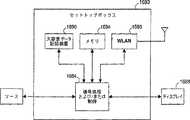
図16Dを参照すると、本発明はセットトップボックス1680に実装しうる。本発明は、セットトップボックス1680の、一般的に図16Dでは1684として特定される処理および/または制御回路、WLANインタフェース1696、および/または大容量データ記憶装置1690を実装してよい。セットトップボックス1680はブロードバンドソースなどのソースから信号を受け取り、テレビおよび/またはモニタおよび/または他のビデオおよび/または音声出力デバイスなどのディスプレイ1688に適した、標準音声/映像信号および/または高精細音声/映像信号を出力してよい。セットトップボックス1680内の信号処理および/または制御回路1684および/または他の回路(不図示)は、データ処理、符号化および/または暗号化、計算、データフォーマッティングおよび/またはその他のセットトップボックス機能を行いうる。 Referring to FIG. 16D, the present invention may be implemented in a
セットトップボックス1680は、データを不揮発な形で記憶する大容量データ記憶装置1690と通信しうる。大容量データ記憶装置1690は、ハードディスクドライブ(HDD)および/またはデジタルバーサタイルディスク(DVD)ドライブなどの、光学記憶デバイスおよび/または磁気記憶デバイスを含みうる。HDDは、直径が約1.8"より小さい一以上のプラッタを含むミニHDDであってもよい。セットトップボックス1680は、RAM、ROM、フラッシュメモリなどの低レイテンシー不揮発性メモリ、および/または他の適切な電子データ記憶装置などのメモリ1694に接続されうる。セットトップボックス1680はWLANインタフェース1696を介したWLANへの接続を支援しうる。 Set
図16Eを参照すると、本発明は、メディアプレーヤ1700に実装しうる。本発明は、メディアプレーヤ1700の、一般的に図16Eでは1704として特定される処理および/または制御回路、WLANインタフェース1716、および/または大容量データ記憶装置1710を実装してよい。幾らかの実施例においては、メディアプレーヤ1700は、ディスプレイ1707、および/またはキーパッド、タッチパッドなどのユーザ入力1708を含む。幾らかの実施例においては、メディアプレーヤ1700は、典型的にメニュー、ドロップダウンメニュー、アイコンおよび/またはポイントアンドクリックインタフェースをディスプレイ1707および/またはユーザ入力1708を介して利用するグラフィカルユーザインタフェース(GUI)を利用しうる。メディアプレーヤ1700はさらに、スピーカおよび/または音声出力ジャックなどの音声出力1709を含む。メディアプレーヤ1700の信号処理および/または制御回路1704および/または他の回路(不図示)は、データ処理、符号化および/または暗号化、計算、データフォーマッティングおよび/またはその他のメディアプレーヤ機能を行いうる。 Referring to FIG. 16E, the present invention may be implemented in a
メディアプレーヤ1700は、圧縮された音声および/または映像コンテンツなどのデータを不揮発な形で記憶する大容量データ記憶装置1710と連通しうる。幾らかの実施形態においては、圧縮された音声ファイルは、MP3形式あるいは他の適切な圧縮された音声および/または映像形式に準拠したファイルを含む。大容量データ記憶装置1710は、ハードディスクドライブ(HDD)および/またはデジタルバーサタイルディスク(DVD)ドライブなどの、光学記憶デバイスおよび/または磁気記憶デバイスを含みうる。HDDは、直径が約1.8"より小さい一以上のプラッタを含むミニHDDであってもよい。メディアプレーヤ1700は、RAM、ROM、フラッシュメモリなどの低レイテンシー不揮発性メモリ、および/または他の適切な電子データ記憶装置などのメモリ1714に接続されうる。メディアプレーヤ1700はWLANインタフェース1716を介したWLANへの接続を支援しうる。これら記載されたものに加えて他の実施例も考えられる。
入力フレームシーケンスから動き補償されたフレームを効率よく且つ正確に補間する様々な技法を含む、動き補償画像レートコンバータに係るシステムおよび方法を記載してきた。当業者であれば、本発明が記載された実施形態以外の方法によっても実施できることを理解するであろうし、記載された実施形態は例示を目的としたものであって、それに限定することは意図していない。本発明は以下に記載する請求項によってのみ限定される。 Systems and methods for motion compensated image rate converters have been described, including various techniques for efficiently and accurately interpolating motion compensated frames from an input frame sequence. One skilled in the art will appreciate that the present invention may be practiced in other ways than those described, which are intended to be illustrative and not limiting. Not done. The invention is limited only by the claims set forth below.
Claims (72)
Translated fromJapanese現在のフレームと参照フレームとを少なくとも有する入力信号を受信する工程と、
前記参照フレームと前記現在のフレームとの間のグローバル動きを推定して、少なくとも1つのアフィン動きパラメータを生成する工程と、
前記参照フレームと前記現在のフレームとの間のローカル動きを推定して、少なくとも1つの動きベクトルを生成する工程と、を備え、
前記少なくとも1つのアフィン動きパラメータは、前記参照フレームと前記現在のフレームとの間の第1領域の前記グローバル動きを推定し、
前記少なくとも1つの動きベクトルは、前記参照フレームと前記現在のフレームとの間の第2領域のローカル動きを推定する、方法。A method for applying motion estimation, comprising:
Receiving an input signal having at least a current frame and a reference frame;
Estimating global motion between the reference frame and the current frame to generate at least one affine motion parameter;
Estimating local motion between the reference frame and the current frame to generate at least one motion vector;
The at least one affine motion parameter estimates the global motion of a first region between the reference frame and the current frame;
The method, wherein the at least one motion vector estimates a local motion of a second region between the reference frame and the current frame.
前記少なくとも1つの粗いアフィンパラメータをリファインして、前記少なくとも1つのアフィン動きパラメータを生成する工程と、をさらに備える、請求項1に記載の方法。Generating at least one coarse affine parameter;
The method of claim 1, further comprising refining the at least one coarse affine parameter to generate the at least one affine motion parameter.
前記少なくとも1つのアフィン動きパラメータは、前記第1領域の動き補償に利用される、請求項1に記載の方法。The first region is a background region of the current frame;
The method of claim 1, wherein the at least one affine motion parameter is utilized for motion compensation of the first region.
前記参照フレームについて計算した前記隣接領域の動きベクトルを利用して、前記現在のフレームの前記第2領域の前記少なくとも1つの動きベクトルを生成する工程と、をさらに備え、
前記少なくとも1つの動きベクトルは、ローカル動きベクトルである、請求項1に記載の方法。Identifying an adjacent region adjacent to the second region of the reference frame;
Generating the at least one motion vector of the second region of the current frame using the motion vector of the adjacent region calculated for the reference frame; and
The method of claim 1, wherein the at least one motion vector is a local motion vector.
前記隣接領域に対応するアフィン動きパラメータを計算する工程と、
前記計算されたアフィン動きパラメータを利用して、前記第2領域の前記少なくとも1つの動きベクトルを生成する工程と、をさらに備え、
前記少なくとも1つの動きベクトルは、補正グローバル動きベクトルである、請求項1に記載の方法。Identifying an adjacent region adjacent to the second region of the reference frame;
Calculating an affine motion parameter corresponding to the adjacent region;
Generating the at least one motion vector of the second region using the calculated affine motion parameters; and
The method of claim 1, wherein the at least one motion vector is a corrected global motion vector.
現在のフレームと参照フレームとを少なくとも有する入力信号を受信する工程と、
前記現在のフレームと前記参照フレームとを位相相関させる工程と、
前記位相相関に基づいて前記現在のフレームと前記参照フレームとの間のグローバル並進動きを推定する少なくとも1つのアフィンパラメータを計算する工程と、を備える、方法。A global motion estimation method,
Receiving an input signal having at least a current frame and a reference frame;
Phase correlating the current frame with the reference frame;
Calculating at least one affine parameter that estimates a global translational motion between the current frame and the reference frame based on the phase correlation.
デシメーションファクタにより前記現在のフレームおよび前記参照フレームをそれぞれデシメーションする工程と、
前記デシメーションされた現在のフレームおよび参照フレームをフーリエ変換する工程と、
前記変換された現在のフレームに相関する位相を、前記変換された参照フレームに相関する位相から減算して、位相差アレイを生成する工程と、
前記位相差アレイの指数を逆フーリエ変換して、相関面を生成する工程と、を含む、請求項8に記載の方法。The phase correlating the current frame and the reference frame comprises:
Decimating the current frame and the reference frame, respectively, with a decimation factor;
Fourier transforming the decimated current frame and reference frame;
Subtracting the phase correlated to the transformed current frame from the phase correlated to the transformed reference frame to generate a phase difference array;
The method of claim 8, further comprising: inverse Fourier transforming the exponent of the phase difference array to generate a correlation surface.
前記更新された参照フレームと前記現在のフレームとの間の差を求める工程と、
前記少なくとも1つのアフィンパラメータをリファインして前記差を最小にする工程と、をさらに備える、請求項8に記載の方法。Updating the reference frame using the at least one affine parameter;
Determining a difference between the updated reference frame and the current frame;
9. The method of claim 8, further comprising refining the at least one affine parameter to minimize the difference.
前記現在のフレームと前記参照フレームとの間のグローバル動きを推定する少なくとも1つのアフィンパラメータを提供する工程と、
前記少なくとも1つのアフィンパラメータに基づいて、前記現在のフレームの前景領域および背景領域を特定するセグメンテーションマスクを生成する工程と、
前記現在のフレームの大きなエッジ強さを有する領域を特定するオブジェクトエッジ強さマップを生成する工程と、
前記対象領域との関連で、前記前景領域、前記背景領域、および前記大きなエッジ強さを有する領域に基づいて、前記対象領域について前記少なくとも1つの動きベクトルを計算する工程と、を備える、方法。A method for generating at least one motion vector for a target region of a current frame in relation to a reference frame, comprising:
Providing at least one affine parameter that estimates global motion between the current frame and the reference frame;
Generating a segmentation mask identifying a foreground region and a background region of the current frame based on the at least one affine parameter;
Generating an object edge strength map identifying a region having a large edge strength of the current frame;
Calculating the at least one motion vector for the target region based on the foreground region, the background region, and the region having a large edge strength in relation to the target region.
グローバル動きベクトル、補正グローバル動きベクトル、およびローカル動きベクトルのうち少なくとも1つを計算する工程を含む、請求項13に記載の方法。Calculating the at least one motion vector comprises:
The method of claim 13, comprising calculating at least one of a global motion vector, a corrected global motion vector, and a local motion vector.
前記少なくとも1つのアフィンパラメータを利用して前記参照フレームを更新する工程と、
前記更新された参照フレームと前記現在のフレームとの間の差異フレームを求める工程と、
前記差異フレームの各領域を第1閾値と比較して、前記領域を前記前景領域および前記背景領域のいずれかに分類する工程と、を含む、請求項13に記載の方法。The step of generating the segmentation mask includes:
Updating the reference frame using the at least one affine parameter;
Determining a difference frame between the updated reference frame and the current frame;
14. The method of claim 13, comprising comparing each region of the difference frame with a first threshold and classifying the region as either the foreground region or the background region.
前記オブジェクトが占める面積を数量化する工程と、
前記数量化された面積を第2閾値と比較して、前記少なくとも2つの接続された領域の各々を、前記前景領域および前記背景領域のいずれかに再分類する工程と、をさらに備える、請求項15に記載の方法。Determining an object having at least two connected regions within the segmentation mask;
Quantifying the area occupied by the object;
Comparing the quantified area with a second threshold and reclassifying each of the at least two connected regions into either the foreground region or the background region. 15. The method according to 15.
前記現在のフレームのサブ領域の垂直方向および水平方向に相関する複数の固有値を生成する工程と、
前記複数の固有値の最大値を決定する工程と、を含み、
前記最大値が画定する範囲に実質的に在る固有値を有する前記サブ領域の各々は、大きなエッジ強さを有する領域である、請求項13に記載の方法。The step of generating the object edge strength map includes:
Generating a plurality of eigenvalues correlated in the vertical and horizontal directions of the sub-region of the current frame;
Determining a maximum value of the plurality of eigenvalues,
The method of claim 13, wherein each of the sub-regions having eigenvalues substantially within a range defined by the maximum value is a region having a large edge strength.
前記対象領域は、前記現在のフレームに適用された前記セグメンテーションマスクと前記オブジェクトエッジ強さマップとの組み合わせから選択される、請求項13に記載の方法。Applying at least one of median filtering, edge matching filtering, and Gaussian filtering to the motion vector corresponding to the target region;
The method of claim 13, wherein the region of interest is selected from a combination of the segmentation mask applied to the current frame and the object edge strength map.
現在のフレームと参照フレームとを少なくとも有する入力信号を受信する工程と、
前記現在のフレームと前記参照フレームとを処理する工程と、
前記処理された現在のフレームと前記処理された参照フレームとの間のグローバル動きおよびローカル動きそれぞれを特徴付けるアフィングローバル動きパラメータおよび動きベクトルのうち少なくとも1つを提供する工程と、
前記アフィングローバル動きパラメータと前記動きベクトルのうち少なくとも1つを利用して、前記処理された現在のフレームと前記処理された参照フレームとの間に少なくとも1つのフレームを補間する、動き補償補間を行う工程と、を備える、方法。A method for performing motion compensated frame rate conversion, comprising:
Receiving an input signal having at least a current frame and a reference frame;
Processing the current frame and the reference frame;
Providing at least one of affine global motion parameters and motion vectors characterizing global motion and local motion, respectively, between the processed current frame and the processed reference frame;
Performing motion compensated interpolation using at least one of the affine global motion parameter and the motion vector to interpolate at least one frame between the processed current frame and the processed reference frame A method comprising the steps of:
前記出力信号は、前記入力信号の本来のフレームレートより早いフレームレートを有する、請求項20に記載の方法。Further comprising post-processing the motion compensated interpolated output signal;
21. The method of claim 20, wherein the output signal has a frame rate that is faster than an original frame rate of the input signal.
前記信号は、前記入力信号の本来のフレームレートに略等しいフレームレートを有する、請求項20に記載の方法。Further comprising post-processing the processed current frame and the processed reference frame to generate a signal to perform the motion compensated interpolation;
21. The method of claim 20, wherein the signal has a frame rate that is approximately equal to an original frame rate of the input signal.
前記現在のフレームと前記参照フレームとに対してノイズ低減およびデインターレースのうち少なくとも1つを行う工程を含む、請求項20に記載の方法。Processing the current frame and the reference frame comprises:
21. The method of claim 20, comprising performing at least one of noise reduction and deinterlacing on the current frame and the reference frame.
現在のフレームと参照フレームとを少なくとも有する入力信号を受信する回路と、
前記参照フレームと前記現在のフレームとの間のグローバル動きを推定して、少なくとも1つのアフィン動きパラメータを生成するグローバルアフィン動き推定モジュールと、
前記参照フレームと前記現在のフレームとの間のローカル動きを推定して、少なくとも1つの動きベクトルを生成するローカル動き補正モジュールと、を備え、
前記少なくとも1つのアフィン動きパラメータは、前記参照フレームと前記現在のフレームとの間の第1領域の前記グローバル動きを推定し、
前記少なくとも1つの動きベクトルは、前記参照フレームと前記現在のフレームとの間の第2領域のローカル動きを推定する、動き補償フレームレートコンバータ。A motion compensated frame rate converter,
A circuit for receiving an input signal having at least a current frame and a reference frame;
A global affine motion estimation module that estimates global motion between the reference frame and the current frame to generate at least one affine motion parameter;
A local motion compensation module that estimates local motion between the reference frame and the current frame to generate at least one motion vector;
The at least one affine motion parameter estimates the global motion of a first region between the reference frame and the current frame;
A motion compensated frame rate converter, wherein the at least one motion vector estimates a local motion of a second region between the reference frame and the current frame.
少なくとも1つの粗いアフィンパラメータを生成するグローバル並進推定・アフィン予測モジュールと、
前記少なくとも1つの粗いアフィンパラメータをリファインして、前記少なくとも1つのアフィン動きパラメータを生成するアフィンパラメータリファインモジュールと、を含む、請求項24に記載の動き補償フレームレートコンバータ。The global affine motion estimation module includes:
A global translation estimation and affine prediction module that generates at least one coarse affine parameter;
25. The motion compensated frame rate converter of claim 24, comprising: an affine parameter refinement module that refines the at least one coarse affine parameter to produce the at least one affine motion parameter.
前記少なくとも1つのアフィン動きパラメータは、前記第1領域の動き補償に利用される、請求項24に記載の動き補償フレームレートコンバータ。The first region is a background region of the current frame;
25. The motion compensated frame rate converter of claim 24, wherein the at least one affine motion parameter is utilized for motion compensation of the first region.
前記参照フレームの前記第2領域に隣接する隣接領域を特定する回路と、
前記参照フレームについて計算した前記隣接領域の動きベクトルを利用して、前記現在のフレームの前記第2領域の前記少なくとも1つの動きベクトルを生成するローカル動き推定モジュールと、を含み、
前記少なくとも1つの動きベクトルは、ローカル動きベクトルである、請求項24に記載の動き補償フレームレートコンバータ。The local motion compensation module includes:
A circuit for specifying an adjacent region adjacent to the second region of the reference frame;
A local motion estimation module that generates the at least one motion vector of the second region of the current frame using the motion vector of the adjacent region calculated for the reference frame;
25. A motion compensated frame rate converter according to claim 24, wherein the at least one motion vector is a local motion vector.
前記参照フレームの前記第2領域に隣接する隣接領域を特定する回路と、
前記隣接領域について計算したアフィン動きパラメータを利用して、前記第2領域の前記少なくとも1つの動きベクトルを生成する補正グローバル動き推定モジュールと、を含み、
前記少なくとも1つの動きベクトルは、補正グローバル動きベクトルである、請求項24に記載の動き補償フレームレートコンバータ。The local motion compensation module includes:
A circuit for specifying an adjacent region adjacent to the second region of the reference frame;
A corrected global motion estimation module that generates the at least one motion vector of the second region using affine motion parameters calculated for the adjacent region;
25. A motion compensated frame rate converter according to claim 24, wherein the at least one motion vector is a corrected global motion vector.
現在のフレームと参照フレームとを少なくとも有する入力信号を受信する回路と、
前記現在のフレームと前記参照フレームとを位相相関させる位相相関モジュールと、
前記位相相関に基づいて前記現在のフレームと前記参照フレームとの間のグローバル並進動きを推定する少なくとも1つのアフィンパラメータを計算する回路と、を備える、グローバル並進推定モジュール。A global translation estimation module,
A circuit for receiving an input signal having at least a current frame and a reference frame;
A phase correlation module that phase correlates the current frame and the reference frame;
A global translation estimation module comprising: at least one affine parameter that estimates global translation motion between the current frame and the reference frame based on the phase correlation.
前記デシメーションされた現在のフレームおよび参照フレームをフーリエ変換する回路と、
前記変換された現在のフレームに相関する位相を、前記変換された参照フレームに相関する位相から減算して、位相差アレイを生成する回路と、
前記位相差アレイの指数を逆フーリエ変換して、相関面を生成する回路と、を備える請求項33に記載のグローバル並進推定モジュール。A circuit for decimating the current frame and the reference frame, respectively, according to a decimation factor;
Circuitry for Fourier transforming the decimated current frame and reference frame;
A circuit that subtracts a phase correlated to the converted current frame from a phase correlated to the converted reference frame to generate a phase difference array;
The global translation estimation module according to claim 33, further comprising: a circuit that generates a correlation surface by performing an inverse Fourier transform on an index of the phase difference array.
前記最大値と前記最大値の位置とを利用して、前記少なくとも1つのアフィンパラメータを計算する、請求項34に記載のグローバル並進推定モジュール。A circuit for determining a maximum value of the correlation surface and a position of the maximum value of the correlation surface;
35. The global translation estimation module according to claim 34, wherein the at least one affine parameter is calculated using the maximum value and the position of the maximum value.
前記アフィンパラメータリファインモジュールは、
前記少なくとも1つのアフィンパラメータに基づいて前記参照フレームを更新する回路と、
前記更新された参照フレームと前記現在のフレームとの間の差を求める回路と、
前記少なくとも1つのアフィンパラメータをリファインして前記差を最小にする回路と、を含む、請求項33に記載のグローバル並進推定モジュール。The at least one affine parameter is provided to an affine parameter refinement module coupled to the global translation estimation module;
The affine parameter refinement module is
A circuit for updating the reference frame based on the at least one affine parameter;
Circuitry for determining a difference between the updated reference frame and the current frame;
34. A global translation estimation module according to claim 33, comprising circuitry for refining the at least one affine parameter to minimize the difference.
現在のフレームの前景領域および背景領域を特定するセグメンテーションマスクと、
前記現在のフレームの大きなエッジ強さを有する領域を特定するオブジェクトエッジ強さマップと、
対象領域との関連で、前記前景領域、前記背景領域、および前記大きなエッジ強さを有する領域に基づいて、前記対象領域について少なくとも1つの動きベクトルを計算する回路と、を備える、ローカル動き補正モジュール。A local motion compensation module,
A segmentation mask that identifies the foreground and background areas of the current frame;
An object edge strength map identifying a region having a large edge strength of the current frame;
A local motion correction module comprising: a circuit that calculates at least one motion vector for the target region based on the foreground region, the background region, and the region having the large edge strength in relation to the target region. .
前記対象領域について、補正グローバル動きベクトルおよびローカル動きベクトルのうち少なくとも1つを計算する回路を含む、請求項38に記載のローカル動き補正モジュール。The circuit for calculating the at least one motion vector comprises:
39. The local motion correction module according to claim 38, comprising circuitry for calculating at least one of a corrected global motion vector and a local motion vector for the region of interest.
前記現在のフレームと前記参照フレームとの間のグローバル動きを特徴付ける少なくとも1つのアフィンパラメータを利用して、前記参照フレームを更新する回路と、
前記更新された参照フレームと前記現在のフレームとの間の差異フレームを求める回路と、
前記差異フレームの各領域を第1閾値と比較して、前記領域を前記前景領域および前記背景領域のいずれかに分類する回路と、を含む回路により生成される、請求項38に記載のローカル動き補正モジュール。The segmentation mask is
Circuitry for updating the reference frame utilizing at least one affine parameter characterizing global motion between the current frame and the reference frame;
Circuitry for determining a difference frame between the updated reference frame and the current frame;
39. The local motion of claim 38, wherein the local motion is generated by a circuit comprising: comparing each region of the difference frame with a first threshold and classifying the region into one of the foreground region and the background region. Correction module.
前記セグメンテーションマスク内に少なくとも2つの接続された領域を有するオブジェクトを決定する回路と、
前記オブジェクトが占める面積を数量化する回路と、
前記数量化された面積を第2閾値と比較して、前記少なくとも2つの接続された領域の各々を、前記前景領域および前記背景領域のいずれかに再分類する回路と、を含む回路により生成される、請求項40に記載のローカル動き補正モジュール。The segmentation mask further includes:
Circuitry for determining an object having at least two connected regions in the segmentation mask;
A circuit for quantifying the area occupied by the object;
A circuit that compares the quantified area with a second threshold and reclassifies each of the at least two connected regions into either the foreground region or the background region. 41. The local motion compensation module of claim 40.
前記現在のフレームのサブ領域の垂直方向および水平方向に相関する複数の固有値を生成する回路と、
前記複数の固有値の最大値を決定する回路と、を含む回路により生成され、
前記最大値が画定する範囲に実質的に在る固有値を有する前記サブ領域の各々は、大きなエッジ強さを有する領域として適合される、請求項38に記載のローカル動き補正モジュール。The object edge strength map is:
A circuit for generating a plurality of eigenvalues correlated in the vertical and horizontal directions of the sub-region of the current frame;
A circuit for determining a maximum value of the plurality of eigenvalues, and
40. The local motion correction module of claim 38, wherein each of the sub-regions having eigenvalues substantially within a range defined by the maximum value is adapted as a region having a large edge strength.
前記対象領域は、前記現在のフレームに適用された前記セグメンテーションマスクと前記オブジェクトエッジ強さマップとの組み合わせから選択される、請求項38に記載のローカル動き補正モジュール。Filtering the motion vector corresponding to the region of interest using at least one of a median filter, an edge fitting filter, and a Gaussian filter;
39. The local motion correction module of claim 38, wherein the region of interest is selected from a combination of the segmentation mask applied to the current frame and the object edge strength map.
参照フレームと現在のフレームとを少なくとも有する入力信号を受信する回路と、
前記参照フレームと前記現在のフレームとを処理する処理モジュールと、
動き補償フレームレートコンバータと、を備え、
前記動き補償フレームレートコンバータは、
前記処理された現在のフレームと前記処理された参照フレームとの間のグローバル動きおよびローカル動きそれぞれを特徴付けるアフィングローバル動きパラメータおよび動きベクトルのうち少なくとも1つを提供する回路と、
前記アフィングローバル動きパラメータと前記動きベクトルのうち少なくとも1つを利用して、前記処理された現在のフレームと前記処理された参照フレームとの間に少なくとも1つのフレームを補間する、動き補償補間を行う回路と、を含む、動き補償画像レートコンバータ。A motion compensated image rate converter,
A circuit for receiving an input signal having at least a reference frame and a current frame;
A processing module for processing the reference frame and the current frame;
A motion compensation frame rate converter, and
The motion compensated frame rate converter
A circuit that provides at least one of affine global motion parameters and motion vectors that characterize global and local motion, respectively, between the processed current frame and the processed reference frame;
Performing motion compensated interpolation using at least one of the affine global motion parameter and the motion vector to interpolate at least one frame between the processed current frame and the processed reference frame And a motion compensated image rate converter.
前記出力信号は、前記入力信号の本来のフレームレートより高いフレームレートを有する、請求項45に記載の動き補償画像レートコンバータ。A post-processing module for processing an output signal of the motion compensation frame rate converter;
46. The motion compensated image rate converter of claim 45, wherein the output signal has a frame rate that is higher than an original frame rate of the input signal.
前記信号は、前記入力信号の本来のフレームレートに略等しいフレームレートを有するよう適合される、請求項45に記載の動き補償画像レートコンバータ。A post-processing module that processes the processed current frame and the processed reference frame to generate a signal to be supplied to the motion compensated frame rate converter;
46. The motion compensated image rate converter of claim 45, wherein the signal is adapted to have a frame rate that is approximately equal to an original frame rate of the input signal.
前記現在のフレームと前記参照フレームとに対してノイズ低減およびデインターレースのうち少なくとも1つを行う回路を含む、請求項45に記載の動き補償画像レートコンバータ。The processing module is
46. The motion compensated image rate converter of claim 45, including circuitry that performs at least one of noise reduction and deinterlacing on the current frame and the reference frame.
参照フレームと現在のフレームとを少なくとも有する入力信号を受信する手段と、
前記参照フレームと前記現在のフレームとの間のグローバル動きを推定して、少なくとも1つのアフィン動きパラメータを生成する手段と、
前記参照フレームと前記現在のフレームとの間のローカル動きを推定して、少なくとも1つの動きベクトルを生成する手段と、を備え、
前記少なくとも1つのアフィン動きパラメータは、前記参照フレームと前記現在のフレームとの間の第1領域の前記グローバル動きを推定し、
前記少なくとも1つの動きベクトルは、前記参照フレームと前記現在のフレームとの間の第2領域のローカル動きを推定する、動き補償フレームレートコンバータ。A motion compensated frame rate converter,
Means for receiving an input signal having at least a reference frame and a current frame;
Means for estimating global motion between the reference frame and the current frame to generate at least one affine motion parameter;
Means for estimating local motion between the reference frame and the current frame to generate at least one motion vector;
The at least one affine motion parameter estimates the global motion of a first region between the reference frame and the current frame;
A motion compensated frame rate converter, wherein the at least one motion vector estimates a local motion of a second region between the reference frame and the current frame.
少なくとも1つの粗いアフィンパラメータを生成する手段と、
前記少なくとも1つの粗いアフィンパラメータをリファインして、前記少なくとも1つのアフィン動きパラメータを生成する手段と、をさらに含む、請求項49に記載の動き補償フレームレートコンバータ。Means for estimating global motion between the reference frame and the current frame;
Means for generating at least one coarse affine parameter;
50. The motion compensated frame rate converter of claim 49, further comprising means for refining the at least one coarse affine parameter to generate the at least one affine motion parameter.
前記少なくとも1つのアフィン動きパラメータは、前記第1領域の動き補償に利用される、請求項49に記載の動き補償フレームレートコンバータ。The first region is a background region of the current frame;
50. The motion compensated frame rate converter of claim 49, wherein the at least one affine motion parameter is utilized for motion compensation of the first region.
前記参照フレームの前記第2領域に隣接する隣接領域を特定する手段と、
前記参照フレームについて計算した前記隣接領域の動きベクトルを利用して、前記現在のフレームの前記第2領域の前記少なくとも1つの動きベクトルを生成する手段と、を含み、
前記少なくとも1つの動きベクトルは、ローカル動きベクトルである、請求項49に記載の動き補償フレームレートコンバータ。Means for estimating local motion between the reference frame and the current frame;
Means for identifying an adjacent region adjacent to the second region of the reference frame;
Means for generating the at least one motion vector of the second region of the current frame using a motion vector of the adjacent region calculated for the reference frame;
50. The motion compensated frame rate converter of claim 49, wherein the at least one motion vector is a local motion vector.
前記参照フレームの前記第2領域に隣接する隣接領域を特定する手段と、
前記隣接領域のアフィン動きパラメータを利用して、前記第2領域の前記少なくとも1つの動きベクトルを生成する手段と、を含み、
前記少なくとも1つの動きベクトルは、補正グローバル動きベクトルである、請求項49に記載の動き補償フレームレートコンバータ。Means for estimating local motion between the reference frame and the current frame;
Means for identifying an adjacent region adjacent to the second region of the reference frame;
Means for generating the at least one motion vector of the second region using affine motion parameters of the adjacent region;
50. The motion compensated frame rate converter of claim 49, wherein the at least one motion vector is a corrected global motion vector.
前記現在のフレームと前記参照フレームとを位相相関させる手段と、
前記位相相関に基づいて前記現在のフレームと前記参照フレームとの間のグローバル並進動きを推定する少なくとも1つのアフィンパラメータを計算する手段と、を備える、グローバル並進推定モジュール。Means for receiving an input signal having at least a current frame and a reference frame;
Means for phase correlating the current frame and the reference frame;
Means for calculating at least one affine parameter that estimates a global translational motion between the current frame and the reference frame based on the phase correlation.
デシメーションファクタにより前記現在のフレームおよび前記参照フレームをそれぞれデシメーションする手段と、
前記デシメーションされた現在のフレームおよび参照フレームをフーリエ変換する手段と、
前記変換された現在のフレームに相関する位相を、前記変換された参照フレームに相関する位相から減算して、位相差アレイを生成する手段と、
前記位相差アレイの指数を逆フーリエ変換して、相関面を生成する手段と、をさらに含む請求項57に記載のグローバル並進推定モジュール。Means for phase-correlating the current frame and the reference frame;
Means for decimating the current frame and the reference frame, respectively, by a decimation factor;
Means for Fourier transforming said decimated current frame and reference frame;
Means for subtracting a phase correlated to the transformed current frame from a phase correlated to the transformed reference frame to generate a phase difference array;
58. The global translation estimation module according to claim 57, further comprising: an inverse Fourier transform of an index of the phase difference array to generate a correlation surface.
前記最大値と前記最大値の位置とを利用して、前記少なくとも1つのアフィンパラメータを計算する、請求項58に記載のグローバル並進推定モジュール。Means for determining a maximum value of the correlation surface and a position of the maximum value of the correlation surface;
59. The global translation estimation module of claim 58, wherein the at least one affine parameter is calculated utilizing the maximum value and the position of the maximum value.
前記アフィンパラメータリファインモジュールは、
前記少なくとも1つのアフィンパラメータに基づいて前記参照フレームを更新する手段と、
前記更新された参照フレームと前記現在のフレームとの間の差を求める手段と、
前記少なくとも1つのアフィンパラメータをリファインして前記差を最小にする手段と、を含む、請求項59に記載のグローバル並進推定モジュール。The at least one affine parameter is provided to an affine parameter refinement module coupled to the global translation estimation module;
The affine parameter refinement module is
Means for updating the reference frame based on the at least one affine parameter;
Means for determining a difference between the updated reference frame and the current frame;
60. The global translation estimation module of claim 59, comprising: means for refining the at least one affine parameter to minimize the difference.
前記現在のフレームの大きなエッジ強さを有する領域を特定するオブジェクトエッジ強さマップを生成する手段と、
対象領域との関連で、前記前景領域、前記背景領域、および前記大きなエッジ強さを有する領域に基づいて、前記対象領域について少なくとも1つの動きベクトルを計算する手段と、を備える、ローカル動き補正モジュール。Means for generating a segmentation mask identifying the foreground and background regions of the current frame;
Means for generating an object edge strength map identifying a region having a large edge strength of the current frame;
Means for calculating at least one motion vector for the target region based on the foreground region, the background region, and the region having a large edge strength in relation to the target region. .
前記対象領域について、補正グローバル動きベクトルおよびローカル動きベクトルのうち少なくとも1つを計算する手段を含む、請求項62に記載のローカル動き補正モジュール。The means for calculating the at least one motion vector comprises:
64. The local motion correction module according to claim 62, comprising means for calculating at least one of a corrected global motion vector and a local motion vector for the target region.
前記現在のフレームと前記参照フレームとの間のグローバル動きを特徴付ける少なくとも1つのアフィンパラメータを利用して、前記参照フレームを更新する手段と、
前記更新された参照フレームと前記現在のフレームとの間の差異フレームを求める手段と、
前記差異フレームの各領域を第1閾値と比較して、前記領域を前記前景領域および前記背景領域のいずれかに分類する手段と、を含む、請求項62に記載のローカル動き補正モジュール。The means for generating the segmentation mask comprises:
Means for updating the reference frame utilizing at least one affine parameter characterizing global motion between the current frame and the reference frame;
Means for determining a difference frame between the updated reference frame and the current frame;
63. The local motion correction module according to claim 62, further comprising: comparing each region of the difference frame with a first threshold to classify the region into one of the foreground region and the background region.
前記セグメンテーションマスク内に少なくとも2つの接続された領域を有するオブジェクトを決定する手段と、
前記オブジェクトが占める面積を数量化する手段と、
前記数量化された面積を第2閾値と比較して、前記少なくとも2つの接続された領域の各々を、前記前景領域および前記背景領域のいずれかに再分類する手段と、をさらに含む、請求項64に記載のローカル動き補正モジュール。The means for generating the segmentation mask comprises:
Means for determining an object having at least two connected regions within the segmentation mask;
Means for quantifying the area occupied by the object;
Means for comparing the quantified area with a second threshold and reclassifying each of the at least two connected regions into either the foreground region or the background region. 64. The local motion correction module according to 64.
前記現在のフレームのサブ領域の垂直方向および水平方向に相関する複数の固有値を生成する手段と、
前記複数の固有値の最大値を決定する手段と、を含み、
前記最大値が画定する範囲に実質的に在る固有値を有する前記サブ領域の各々は、大きなエッジ強さを有する領域である、請求項62に記載のローカル動き補正モジュール。The means for generating the object edge strength map includes:
Means for generating a plurality of eigenvalues correlated in the vertical and horizontal directions of the sub-region of the current frame;
Means for determining a maximum value of the plurality of eigenvalues,
64. The local motion correction module according to claim 62, wherein each of the sub-regions having eigenvalues substantially within a range defined by the maximum value is a region having a large edge strength.
前記対象領域は、前記現在のフレームに適用された前記セグメンテーションマスクと前記オブジェクトエッジ強さマップとの組み合わせから選択される、請求項62に記載のローカル動き補正モジュール。Filtering the motion vector corresponding to the region of interest using at least one of median filter means, edge matched filter means, and Gaussian filter means;
64. The local motion correction module of claim 62, wherein the region of interest is selected from a combination of the segmentation mask applied to the current frame and the object edge strength map.
前記現在のフレームと前記参照フレームとを処理する手段と、
前記処理された現在のフレームと前記処理された参照フレームとの間のグローバル動きおよびローカル動きそれぞれを特徴付けるアフィングローバル動きパラメータおよび動きベクトルのうち少なくとも1つを提供する手段と、
前記アフィングローバル動きパラメータと前記動きベクトルのうち少なくとも1つを利用して、前記処理された現在のフレームと前記処理された参照フレームとの間に少なくとも1つのフレームを補間する、動き補償補間を行う手段と、を備える、動き補償画像レートコンバータ。Means for receiving an input signal having at least a current frame and a reference frame;
Means for processing the current frame and the reference frame;
Means for providing at least one of affine global motion parameters and motion vectors characterizing global motion and local motion, respectively, between the processed current frame and the processed reference frame;
Performing motion compensated interpolation using at least one of the affine global motion parameter and the motion vector to interpolate at least one frame between the processed current frame and the processed reference frame And a motion compensated image rate converter.
前記出力信号は、前記入力信号の本来のフレームレートより速いフレームレートを有する、請求項69に記載の動き補償画像レートコンバータ。Means for post-processing the output signal from the means for performing the motion compensated interpolation;
70. The motion compensated image rate converter of claim 69, wherein the output signal has a frame rate that is faster than an original frame rate of the input signal.
前記信号は、前記入力信号の本来のフレームレートに略等しいフレームレートを有するよう適合される、請求項69に記載の動き補償画像レートコンバータ。Means for post-processing the processed current frame and the processed reference frame to generate a signal to be supplied to the means for performing the motion compensated interpolation;
70. The motion compensated image rate converter of claim 69, wherein the signal is adapted to have a frame rate that is approximately equal to an original frame rate of the input signal.
前記現在のフレームと前記参照フレームとに対してノイズ低減およびデインターレースのうち少なくとも1つを行う手段を含む、請求項69に記載の動き補償画像レートコンバータ。Means for processing the current frame and the reference frame;
70. The motion compensated image rate converter of claim 69, comprising means for performing at least one of noise reduction and deinterlacing on the current frame and the reference frame.
Applications Claiming Priority (3)
| Application Number | Priority Date | Filing Date | Title |
|---|---|---|---|
| US81706106P | 2006-06-27 | 2006-06-27 | |
| US11/803,535US8340185B2 (en) | 2006-06-27 | 2007-05-14 | Systems and methods for a motion compensated picture rate converter |
| PCT/US2007/014609WO2008002491A2 (en) | 2006-06-27 | 2007-06-22 | Systems and methods for a motion compensated picture rate converter |
Related Child Applications (1)
| Application Number | Title | Priority Date | Filing Date |
|---|---|---|---|
| JP2012231573ADivisionJP5740690B2 (en) | 2006-06-27 | 2012-10-19 | System and method for motion compensated image rate converter |
Publications (1)
| Publication Number | Publication Date |
|---|---|
| JP2010501127Atrue JP2010501127A (en) | 2010-01-14 |
Family
ID=38846215
Family Applications (2)
| Application Number | Title | Priority Date | Filing Date |
|---|---|---|---|
| JP2009518177APendingJP2010501127A (en) | 2006-06-27 | 2007-06-22 | System and method for motion compensated image rate converter |
| JP2012231573AActiveJP5740690B2 (en) | 2006-06-27 | 2012-10-19 | System and method for motion compensated image rate converter |
Family Applications After (1)
| Application Number | Title | Priority Date | Filing Date |
|---|---|---|---|
| JP2012231573AActiveJP5740690B2 (en) | 2006-06-27 | 2012-10-19 | System and method for motion compensated image rate converter |
Country Status (6)
| Country | Link |
|---|---|
| US (1) | US8340185B2 (en) |
| EP (1) | EP2080362B1 (en) |
| JP (2) | JP2010501127A (en) |
| KR (1) | KR101371577B1 (en) |
| TW (1) | TWI432017B (en) |
| WO (1) | WO2008002491A2 (en) |
Cited By (3)
| Publication number | Priority date | Publication date | Assignee | Title |
|---|---|---|---|---|
| JP2014508455A (en)* | 2011-01-28 | 2014-04-03 | コーニンクレッカ フィリップス エヌ ヴェ | Comparison based on motion vectors of moving objects |
| JP2017532795A (en)* | 2015-08-21 | 2017-11-02 | ▲楽▼視控股(北京)有限公司Le Holdings(Beijing)Co.,Ltd. | Audio video reproduction facility, data display method, and storage medium |
| JPWO2021106499A1 (en)* | 2019-11-29 | 2021-06-03 |
Families Citing this family (76)
| Publication number | Priority date | Publication date | Assignee | Title |
|---|---|---|---|---|
| US7983835B2 (en) | 2004-11-03 | 2011-07-19 | Lagassey Paul J | Modular intelligent transportation system |
| WO2006061421A2 (en)* | 2004-12-09 | 2006-06-15 | Thomson Licensing | Method and apparatus for generating motion compensated pictures |
| US20100014726A1 (en)* | 2006-06-01 | 2010-01-21 | Koninklijke Philips Electronics N.V. | Hierarchical motion estimation |
| US8923400B1 (en)* | 2007-02-16 | 2014-12-30 | Geo Semiconductor Inc | Method and/or apparatus for multiple pass digital image stabilization |
| US20080212687A1 (en)* | 2007-03-02 | 2008-09-04 | Sony Corporation And Sony Electronics Inc. | High accurate subspace extension of phase correlation for global motion estimation |
| US20080304568A1 (en)* | 2007-06-11 | 2008-12-11 | Himax Technologies Limited | Method for motion-compensated frame rate up-conversion |
| US20090030676A1 (en)* | 2007-07-26 | 2009-01-29 | Creative Technology Ltd | Method of deriving a compressed acoustic model for speech recognition |
| US8817878B2 (en)* | 2007-11-07 | 2014-08-26 | Broadcom Corporation | Method and system for motion estimation around a fixed reference vector using a pivot-pixel approach |
| US20090190029A1 (en)* | 2008-01-28 | 2009-07-30 | Te-Hao Chang | Video processing methods and related apparatus |
| KR20090089606A (en)* | 2008-02-19 | 2009-08-24 | 엘지전자 주식회사 | Method for performing FRC function for each input source and broadcast receiver using the method |
| US8477848B1 (en)* | 2008-04-22 | 2013-07-02 | Marvell International Ltd. | Picture rate conversion system architecture |
| US20090268088A1 (en)* | 2008-04-25 | 2009-10-29 | Hui Zhou | Motion adaptive de-interlacer and method for use therewith |
| JP4506875B2 (en)* | 2008-05-19 | 2010-07-21 | ソニー株式会社 | Image processing apparatus and image processing method |
| TWI420401B (en)* | 2008-06-11 | 2013-12-21 | Vatics Inc | Algorithm for feedback type object detection |
| US8374240B1 (en) | 2008-07-10 | 2013-02-12 | Marvell International Ltd. | Image frame management |
| ATE554602T1 (en)* | 2008-08-21 | 2012-05-15 | Vestel Elekt Sanayi Ve Ticaret | METHOD AND DEVICE FOR INCREASE THE FRAME RATE OF A VIDEO SIGNAL |
| CN102187664B (en)* | 2008-09-04 | 2014-08-20 | 独立行政法人科学技术振兴机构 | Video signal converting system |
| US8325796B2 (en) | 2008-09-11 | 2012-12-04 | Google Inc. | System and method for video coding using adaptive segmentation |
| KR20110132324A (en)* | 2008-12-31 | 2011-12-07 | 엠브이3 파트너스 엘엘씨 | Mobile set top box |
| US8630088B2 (en) | 2009-03-27 | 2014-01-14 | Qualcomm Incorporated | Portable docking station for a portable computing device |
| US9201593B2 (en)* | 2009-03-27 | 2015-12-01 | Qualcomm Incorporated | System and method of managing displays at a portable computing device and a portable computing device docking station |
| US8707061B2 (en) | 2009-03-27 | 2014-04-22 | Qualcomm Incorporated | System and method of providing scalable computing between a portable computing device and a portable computing device docking station |
| US9128669B2 (en) | 2009-03-27 | 2015-09-08 | Qualcomm Incorporated | System and method of managing security between a portable computing device and a portable computing device docking station |
| US8653785B2 (en) | 2009-03-27 | 2014-02-18 | Qualcomm Incorporated | System and method of managing power at a portable computing device and a portable computing device docking station |
| JP5225172B2 (en)* | 2009-03-30 | 2013-07-03 | 株式会社東芝 | Image processing device |
| US8520736B2 (en)* | 2009-04-14 | 2013-08-27 | Fastvdo, Llc | Real-time superresolution and video transmission |
| JP5149861B2 (en)* | 2009-05-01 | 2013-02-20 | 富士フイルム株式会社 | Intermediate image generation apparatus and operation control method thereof |
| US20110026596A1 (en)* | 2009-07-28 | 2011-02-03 | Wei Hong | Method and System for Block-Based Motion Estimation for Motion-Compensated Frame Rate Conversion |
| KR101634355B1 (en)* | 2009-09-18 | 2016-06-28 | 삼성전자주식회사 | Apparatus and Method for detecting a motion |
| KR101183781B1 (en)* | 2009-12-22 | 2012-09-17 | 삼성전자주식회사 | Method and apparatus for object detecting/tracking using real time motion estimation of camera |
| US8488007B2 (en)* | 2010-01-19 | 2013-07-16 | Sony Corporation | Method to estimate segmented motion |
| US8896715B2 (en)* | 2010-02-11 | 2014-11-25 | Microsoft Corporation | Generic platform video image stabilization |
| US20110299597A1 (en)* | 2010-06-07 | 2011-12-08 | Sony Corporation | Image processing method using motion estimation and image processing apparatus |
| US8446524B2 (en)* | 2010-06-21 | 2013-05-21 | Realtek Semiconductor Corp. | Apparatus and method for frame rate conversion |
| TWI427609B (en)* | 2010-07-27 | 2014-02-21 | Hannstar Display Corp | Image compensation apparatus and method thereof and field sequential color liquid crystal display using the same |
| JP5381930B2 (en)* | 2010-08-20 | 2014-01-08 | 株式会社Jvcケンウッド | Video control apparatus and video control method |
| TWI459795B (en)* | 2010-12-31 | 2014-11-01 | Altek Corp | Noise reduction method |
| US8711248B2 (en) | 2011-02-25 | 2014-04-29 | Microsoft Corporation | Global alignment for high-dynamic range image generation |
| US8792549B2 (en) | 2011-02-28 | 2014-07-29 | Sony Corporation | Decoder-derived geometric transformations for motion compensated inter prediction |
| US9154799B2 (en) | 2011-04-07 | 2015-10-06 | Google Inc. | Encoding and decoding motion via image segmentation |
| US9824426B2 (en) | 2011-08-01 | 2017-11-21 | Microsoft Technology Licensing, Llc | Reduced latency video stabilization |
| JP5887764B2 (en)* | 2011-08-29 | 2016-03-16 | 株式会社Jvcケンウッド | Motion compensation frame generation apparatus and method |
| KR101805625B1 (en)* | 2011-09-09 | 2017-12-08 | 삼성전자주식회사 | Method and appratus for converting image rate using image scaling |
| KR101903748B1 (en)* | 2011-10-07 | 2018-10-04 | 삼성디스플레이 주식회사 | Display device |
| US9262670B2 (en) | 2012-02-10 | 2016-02-16 | Google Inc. | Adaptive region of interest |
| HK1203261A1 (en) | 2012-05-14 | 2015-10-23 | Luca Rossato | Encoding and reconstruction of residual data based on support information |
| KR101930235B1 (en)* | 2012-05-15 | 2018-12-18 | 삼성전자 주식회사 | Method, device and system for digital image stabilization |
| KR20150056811A (en)* | 2012-11-13 | 2015-05-27 | 인텔 코포레이션 | Content adaptive transform coding for next generation video |
| KR102121558B1 (en)* | 2013-03-15 | 2020-06-10 | 삼성전자주식회사 | Method of stabilizing video image, post-processing device and video encoder including the same |
| CN104113745A (en)* | 2013-04-17 | 2014-10-22 | 咏传电子科技(上海)有限公司 | Display device and image display method thereof |
| US10136063B2 (en) | 2013-07-12 | 2018-11-20 | Hanwha Aerospace Co., Ltd | Image stabilizing method and apparatus |
| KR102069269B1 (en)* | 2014-01-21 | 2020-01-22 | 한화테크윈 주식회사 | Apparatus and method for stabilizing image |
| US9177383B2 (en)* | 2013-08-29 | 2015-11-03 | Analog Devices Global | Facial detection |
| KR101789954B1 (en)* | 2013-12-27 | 2017-10-25 | 인텔 코포레이션 | Content adaptive gain compensated prediction for next generation video coding |
| US9479788B2 (en) | 2014-03-17 | 2016-10-25 | Qualcomm Incorporated | Systems and methods for low complexity encoding and background detection |
| US9392272B1 (en) | 2014-06-02 | 2016-07-12 | Google Inc. | Video coding using adaptive source variance based partitioning |
| US9578324B1 (en) | 2014-06-27 | 2017-02-21 | Google Inc. | Video coding using statistical-based spatially differentiated partitioning |
| JP6757885B2 (en)* | 2015-07-16 | 2020-09-23 | パナソニックIpマネジメント株式会社 | Projection type display device |
| CN105657491A (en)* | 2015-08-21 | 2016-06-08 | 乐视致新电子科技(天津)有限公司 | Audio/video playing equipment |
| KR102452945B1 (en)* | 2015-08-27 | 2022-10-11 | 삼성전자주식회사 | Apparatus and Method for performing Fourier transform |
| US10593015B2 (en)* | 2016-05-04 | 2020-03-17 | Texas Instruments Incorporated | Apparatus and method for efficient motion estimation |
| US10448010B2 (en)* | 2016-10-05 | 2019-10-15 | Qualcomm Incorporated | Motion vector prediction for affine motion models in video coding |
| KR102500462B1 (en)* | 2017-05-17 | 2023-02-16 | 가부시키가이샤 크리프톤 | Image processing device, image processing program and image processing method |
| US10523961B2 (en) | 2017-08-03 | 2019-12-31 | Samsung Electronics Co., Ltd. | Motion estimation method and apparatus for plurality of frames |
| CN108924621B (en)* | 2018-07-12 | 2019-10-29 | 深圳创维-Rgb电子有限公司 | Display methods, device and television set, storage medium |
| CN111325673B (en)* | 2018-12-14 | 2023-06-30 | 瑞昱半导体股份有限公司 | Image processing method and image processing circuit |
| US10896356B2 (en)* | 2019-05-10 | 2021-01-19 | Samsung Electronics Co., Ltd. | Efficient CNN-based solution for video frame interpolation |
| CN110798630B (en)* | 2019-10-30 | 2020-12-29 | 北京市商汤科技开发有限公司 | Image processing method and device, electronic device and storage medium |
| KR102213201B1 (en)* | 2020-01-15 | 2021-02-05 | 한화테크윈 주식회사 | Apparatus and method for stabilizing image |
| TWI736114B (en)* | 2020-01-22 | 2021-08-11 | 宏碁股份有限公司 | Display image compensation method and electronic device |
| CN111369592B (en)* | 2020-03-13 | 2023-07-25 | 浙江工业大学 | A Fast Global Motion Estimation Method Based on Newton Interpolation |
| EP4095791A1 (en) | 2021-05-26 | 2022-11-30 | Samsung Electronics Co., Ltd. | Image signal processor and image processing device |
| EP4399875A4 (en)* | 2021-09-06 | 2025-07-16 | Beijing Dajia Internet Information Tech Co Ltd | Candidate derivation for affine joining mode in video coding |
| US20250071318A1 (en)* | 2022-01-04 | 2025-02-27 | Lg Electronics Inc. | Image encoding/decoding method and device, and recording medium storing bitstream |
| US12328441B2 (en)* | 2023-08-04 | 2025-06-10 | Novatek Microelectronics Corp. | Image processing method based on segmentation map and related video processor |
| CN118570708B (en)* | 2024-08-02 | 2024-10-25 | 淄博思创信息科技有限公司 | Intelligent video analysis method and system |
Citations (4)
| Publication number | Priority date | Publication date | Assignee | Title |
|---|---|---|---|---|
| JPH10145795A (en)* | 1996-11-15 | 1998-05-29 | Nippon Telegr & Teleph Corp <Ntt> | Moving image encoding method, decoding method, moving image encoding device, and moving image decoding device |
| JP2003299101A (en)* | 2002-04-03 | 2003-10-17 | Nippon Telegr & Teleph Corp <Ntt> | Moving image encoding device, moving image decoding device, moving image encoding method, moving image decoding method, moving image encoding program, moving image decoding program, recording medium recording moving image encoding program, recording moving image decoding program Recording media |
| US20040252230A1 (en)* | 2003-06-13 | 2004-12-16 | Microsoft Corporation | Increasing motion smoothness using frame interpolation with motion analysis |
| JP2005318576A (en)* | 2004-04-30 | 2005-11-10 | Matsushita Electric Ind Co Ltd | Motion detection using adaptive space latest vector |
Family Cites Families (21)
| Publication number | Priority date | Publication date | Assignee | Title |
|---|---|---|---|---|
| JPH06176151A (en)* | 1992-12-08 | 1994-06-24 | Sony Corp | Image moving amount detector |
| KR0148154B1 (en) | 1994-06-15 | 1998-09-15 | 김광호 | Method and apparatus for encoding video data according to motion size |
| JP3120664B2 (en)* | 1994-10-19 | 2000-12-25 | 松下電器産業株式会社 | Image encoding device, image decoding device |
| KR0180171B1 (en)* | 1995-06-28 | 1999-05-01 | 배순훈 | Block motion estimation method |
| JP3183155B2 (en) | 1996-03-18 | 2001-07-03 | 株式会社日立製作所 | Image decoding apparatus and image decoding method |
| JP4012267B2 (en)* | 1996-03-30 | 2007-11-21 | 三星電子株式会社 | Video encoding / decoding method and encoding / decoding device capable of object unit processing |
| JPH10191326A (en)* | 1996-11-08 | 1998-07-21 | Sony Corp | Image processor and method therefor |
| JP2000134585A (en) | 1998-10-23 | 2000-05-12 | Hitachi Ltd | Motion vector determination method, image signal frame number conversion method and circuit |
| EP1050850A1 (en)* | 1999-05-03 | 2000-11-08 | THOMSON multimedia | Process for estimating a dominant motion between two frames |
| JP2001054075A (en) | 1999-08-06 | 2001-02-23 | Hitachi Ltd | Image signal motion compensation scan conversion circuit |
| JP3670566B2 (en)* | 2000-10-03 | 2005-07-13 | 日本電信電話株式会社 | Processing time adaptive image encoding method and program recording medium |
| AU2002228884A1 (en) | 2000-11-03 | 2002-05-15 | Compression Science | Video data compression system |
| JP2002369161A (en)* | 2001-06-05 | 2002-12-20 | Sony Corp | Digital watermark embedding processing apparatus, digital watermark embedding processing method, and program |
| JP3823767B2 (en)* | 2001-07-18 | 2006-09-20 | 日本電信電話株式会社 | Moving image foreground / background region separation method, and moving image encoding method using conditional pixel interpolation using the method |
| KR100396558B1 (en)* | 2001-10-25 | 2003-09-02 | 삼성전자주식회사 | Apparatus and method for converting frame and/or field rate using adaptive motion compensation |
| US7321626B2 (en) | 2002-03-08 | 2008-01-22 | Sharp Laboratories Of America, Inc. | System and method for predictive motion estimation using a global motion predictor |
| US20040091047A1 (en)* | 2002-11-11 | 2004-05-13 | Sony Corporation | Method and apparatus for nonlinear multiple motion model and moving boundary extraction |
| JP4015537B2 (en) | 2002-11-22 | 2007-11-28 | 日本電信電話株式会社 | Image encoding method, image decoding method, image encoding device, image decoding device, image encoding program, image decoding program, and recording medium recording these programs |
| US7558320B2 (en)* | 2003-06-13 | 2009-07-07 | Microsoft Corporation | Quality control in frame interpolation with motion analysis |
| WO2005027491A2 (en)* | 2003-09-05 | 2005-03-24 | The Regents Of The University Of California | Global motion estimation image coding and processing |
| JP4220451B2 (en)* | 2004-09-28 | 2009-02-04 | 株式会社東芝 | Interpolated image generating apparatus, interpolated image generating method, and interpolated image generating program |
- 2007
- 2007-05-14USUS11/803,535patent/US8340185B2/enactiveActive
- 2007-06-22WOPCT/US2007/014609patent/WO2008002491A2/enactiveApplication Filing
- 2007-06-22KRKR1020087032176Apatent/KR101371577B1/enactiveActive
- 2007-06-22JPJP2009518177Apatent/JP2010501127A/enactivePending
- 2007-06-22EPEP07809823.3Apatent/EP2080362B1/enactiveActive
- 2007-06-26TWTW096123121Apatent/TWI432017B/ennot_activeIP Right Cessation
- 2012
- 2012-10-19JPJP2012231573Apatent/JP5740690B2/enactiveActive
Patent Citations (4)
| Publication number | Priority date | Publication date | Assignee | Title |
|---|---|---|---|---|
| JPH10145795A (en)* | 1996-11-15 | 1998-05-29 | Nippon Telegr & Teleph Corp <Ntt> | Moving image encoding method, decoding method, moving image encoding device, and moving image decoding device |
| JP2003299101A (en)* | 2002-04-03 | 2003-10-17 | Nippon Telegr & Teleph Corp <Ntt> | Moving image encoding device, moving image decoding device, moving image encoding method, moving image decoding method, moving image encoding program, moving image decoding program, recording medium recording moving image encoding program, recording moving image decoding program Recording media |
| US20040252230A1 (en)* | 2003-06-13 | 2004-12-16 | Microsoft Corporation | Increasing motion smoothness using frame interpolation with motion analysis |
| JP2005318576A (en)* | 2004-04-30 | 2005-11-10 | Matsushita Electric Ind Co Ltd | Motion detection using adaptive space latest vector |
Cited By (4)
| Publication number | Priority date | Publication date | Assignee | Title |
|---|---|---|---|---|
| JP2014508455A (en)* | 2011-01-28 | 2014-04-03 | コーニンクレッカ フィリップス エヌ ヴェ | Comparison based on motion vectors of moving objects |
| JP2017532795A (en)* | 2015-08-21 | 2017-11-02 | ▲楽▼視控股(北京)有限公司Le Holdings(Beijing)Co.,Ltd. | Audio video reproduction facility, data display method, and storage medium |
| JPWO2021106499A1 (en)* | 2019-11-29 | 2021-06-03 | ||
| WO2021106499A1 (en)* | 2019-11-29 | 2021-06-03 | 株式会社朋栄 | Rolling shutter video stabilization and motion blur elimination processing method, and device therefor |
Also Published As
| Publication number | Publication date |
|---|---|
| EP2080362A2 (en) | 2009-07-22 |
| KR101371577B1 (en) | 2014-03-18 |
| KR20090034836A (en) | 2009-04-08 |
| US8340185B2 (en) | 2012-12-25 |
| EP2080362B1 (en) | 2021-05-12 |
| WO2008002491A2 (en) | 2008-01-03 |
| WO2008002491A3 (en) | 2010-04-29 |
| JP2013048465A (en) | 2013-03-07 |
| TWI432017B (en) | 2014-03-21 |
| US20070297513A1 (en) | 2007-12-27 |
| TW200818872A (en) | 2008-04-16 |
| JP5740690B2 (en) | 2015-06-24 |
Similar Documents
| Publication | Publication Date | Title |
|---|---|---|
| JP5740690B2 (en) | System and method for motion compensated image rate converter | |
| JP5594968B2 (en) | Method and apparatus for determining motion between video images | |
| US7519230B2 (en) | Background motion vector detection | |
| US20100123792A1 (en) | Image processing device, image processing method and program | |
| CN100438609C (en) | Image processing unit with degradation | |
| EP1430724A1 (en) | Motion estimation and/or compensation | |
| US8615036B2 (en) | Generating interpolated frame of video signal with enhancement filter | |
| WO2005027525A1 (en) | Motion vector field re-timing | |
| JP5133038B2 (en) | Image restoration method and image restoration apparatus | |
| US20070116383A1 (en) | Spatial signal conversion | |
| JP4617883B2 (en) | Image processing apparatus and method, program, and recording medium | |
| EP1654703B1 (en) | Graphics overlay detection | |
| JP5197374B2 (en) | Motion estimation | |
| Lee et al. | Method and architecture design for motion compensated frame interpolation in high-definition video processing | |
| EP1636987A1 (en) | Spatial signal conversion | |
| JP2007060192A (en) | INTERPOLATION FRAME GENERATION DEVICE, METHOD THEREOF, IMAGE DISPLAY SYSTEM, PROGRAM, AND RECORDING MEDIUM | |
| Hong et al. | Multistage block-matching motion estimation for superresolution video reconstruction | |
| Choi et al. | Improvement on optical flow based video deinterlacing by adopting flow vector and intensity reliabilities | |
| US8897584B2 (en) | Image processing apparatus and image processing method | |
| KR101079998B1 (en) | Spatial interpolation method and apparatus | |
| Tu et al. | A robust spatial-temporal line-warping based deinterlacing method | |
| Lee et al. | Spatiotemporal deinterlacing using a maximum a posteriori estimator based on multiple-field registration |
Legal Events
| Date | Code | Title | Description |
|---|---|---|---|
| A621 | Written request for application examination | Free format text:JAPANESE INTERMEDIATE CODE: A621 Effective date:20100524 | |
| A977 | Report on retrieval | Free format text:JAPANESE INTERMEDIATE CODE: A971007 Effective date:20111130 | |
| A131 | Notification of reasons for refusal | Free format text:JAPANESE INTERMEDIATE CODE: A131 Effective date:20111206 | |
| A601 | Written request for extension of time | Free format text:JAPANESE INTERMEDIATE CODE: A601 Effective date:20120306 | |
| A602 | Written permission of extension of time | Free format text:JAPANESE INTERMEDIATE CODE: A602 Effective date:20120313 | |
| A521 | Request for written amendment filed | Free format text:JAPANESE INTERMEDIATE CODE: A523 Effective date:20120406 | |
| A02 | Decision of refusal | Free format text:JAPANESE INTERMEDIATE CODE: A02 Effective date:20120619 | |
| A521 | Request for written amendment filed | Free format text:JAPANESE INTERMEDIATE CODE: A523 Effective date:20121019 | |
| A911 | Transfer to examiner for re-examination before appeal (zenchi) | Free format text:JAPANESE INTERMEDIATE CODE: A911 Effective date:20121029 | |
| A912 | Re-examination (zenchi) completed and case transferred to appeal board | Free format text:JAPANESE INTERMEDIATE CODE: A912 Effective date:20121122 | |
| RD02 | Notification of acceptance of power of attorney | Free format text:JAPANESE INTERMEDIATE CODE: A7422 Effective date:20180608 |