JP2010501058A - Displacement unit and universal shaft provided with the displacement unit - Google Patents
Displacement unit and universal shaft provided with the displacement unitDownload PDFInfo
- Publication number
- JP2010501058A JP2010501058AJP2009524073AJP2009524073AJP2010501058AJP 2010501058 AJP2010501058 AJP 2010501058AJP 2009524073 AJP2009524073 AJP 2009524073AJP 2009524073 AJP2009524073 AJP 2009524073AJP 2010501058 AJP2010501058 AJP 2010501058A
- Authority
- JP
- Japan
- Prior art keywords
- cage
- displacement unit
- passage
- joint
- unit according
- Prior art date
- Legal status (The legal status is an assumption and is not a legal conclusion. Google has not performed a legal analysis and makes no representation as to the accuracy of the status listed.)
- Pending
Links
- 238000006073displacement reactionMethods0.000titleclaimsabstractdescription41
- 239000002184metalSubstances0.000claimsdescription3
- 238000005096rolling processMethods0.000description5
- 230000005540biological transmissionEffects0.000description2
- 238000013461designMethods0.000description1
- 238000011161developmentMethods0.000description1
- 238000003780insertionMethods0.000description1
- 230000037431insertionEffects0.000description1
- 238000000034methodMethods0.000description1
- 238000009828non-uniform distributionMethods0.000description1
- 238000012545processingMethods0.000description1
Images

Classifications
- F—MECHANICAL ENGINEERING; LIGHTING; HEATING; WEAPONS; BLASTING
- F16—ENGINEERING ELEMENTS AND UNITS; GENERAL MEASURES FOR PRODUCING AND MAINTAINING EFFECTIVE FUNCTIONING OF MACHINES OR INSTALLATIONS; THERMAL INSULATION IN GENERAL
- F16D—COUPLINGS FOR TRANSMITTING ROTATION; CLUTCHES; BRAKES
- F16D3/00—Yielding couplings, i.e. with means permitting movement between the connected parts during the drive
- F16D3/16—Universal joints in which flexibility is produced by means of pivots or sliding or rolling connecting parts
- F16D3/20—Universal joints in which flexibility is produced by means of pivots or sliding or rolling connecting parts one coupling part entering a sleeve of the other coupling part and connected thereto by sliding or rolling members
- F16D3/22—Universal joints in which flexibility is produced by means of pivots or sliding or rolling connecting parts one coupling part entering a sleeve of the other coupling part and connected thereto by sliding or rolling members the rolling members being balls, rollers, or the like, guided in grooves or sockets in both coupling parts
- F16D3/223—Universal joints in which flexibility is produced by means of pivots or sliding or rolling connecting parts one coupling part entering a sleeve of the other coupling part and connected thereto by sliding or rolling members the rolling members being balls, rollers, or the like, guided in grooves or sockets in both coupling parts the rolling members being guided in grooves in both coupling parts
- F16D3/226—Universal joints in which flexibility is produced by means of pivots or sliding or rolling connecting parts one coupling part entering a sleeve of the other coupling part and connected thereto by sliding or rolling members the rolling members being balls, rollers, or the like, guided in grooves or sockets in both coupling parts the rolling members being guided in grooves in both coupling parts the groove centre-lines in each coupling part lying on a cylinder co-axial with the respective coupling part
- F16D3/227—Universal joints in which flexibility is produced by means of pivots or sliding or rolling connecting parts one coupling part entering a sleeve of the other coupling part and connected thereto by sliding or rolling members the rolling members being balls, rollers, or the like, guided in grooves or sockets in both coupling parts the rolling members being guided in grooves in both coupling parts the groove centre-lines in each coupling part lying on a cylinder co-axial with the respective coupling part the joints being telescopic
- F—MECHANICAL ENGINEERING; LIGHTING; HEATING; WEAPONS; BLASTING
- F16—ENGINEERING ELEMENTS AND UNITS; GENERAL MEASURES FOR PRODUCING AND MAINTAINING EFFECTIVE FUNCTIONING OF MACHINES OR INSTALLATIONS; THERMAL INSULATION IN GENERAL
- F16D—COUPLINGS FOR TRANSMITTING ROTATION; CLUTCHES; BRAKES
- F16D3/00—Yielding couplings, i.e. with means permitting movement between the connected parts during the drive
- F16D3/02—Yielding couplings, i.e. with means permitting movement between the connected parts during the drive adapted to specific functions
- F16D3/06—Yielding couplings, i.e. with means permitting movement between the connected parts during the drive adapted to specific functions specially adapted to allow axial displacement
- F16D3/065—Yielding couplings, i.e. with means permitting movement between the connected parts during the drive adapted to specific functions specially adapted to allow axial displacement by means of rolling elements
- F—MECHANICAL ENGINEERING; LIGHTING; HEATING; WEAPONS; BLASTING
- F16—ENGINEERING ELEMENTS AND UNITS; GENERAL MEASURES FOR PRODUCING AND MAINTAINING EFFECTIVE FUNCTIONING OF MACHINES OR INSTALLATIONS; THERMAL INSULATION IN GENERAL
- F16D—COUPLINGS FOR TRANSMITTING ROTATION; CLUTCHES; BRAKES
- F16D3/00—Yielding couplings, i.e. with means permitting movement between the connected parts during the drive
- F16D3/16—Universal joints in which flexibility is produced by means of pivots or sliding or rolling connecting parts
- F16D3/20—Universal joints in which flexibility is produced by means of pivots or sliding or rolling connecting parts one coupling part entering a sleeve of the other coupling part and connected thereto by sliding or rolling members
- F16D3/22—Universal joints in which flexibility is produced by means of pivots or sliding or rolling connecting parts one coupling part entering a sleeve of the other coupling part and connected thereto by sliding or rolling members the rolling members being balls, rollers, or the like, guided in grooves or sockets in both coupling parts
- F16D3/223—Universal joints in which flexibility is produced by means of pivots or sliding or rolling connecting parts one coupling part entering a sleeve of the other coupling part and connected thereto by sliding or rolling members the rolling members being balls, rollers, or the like, guided in grooves or sockets in both coupling parts the rolling members being guided in grooves in both coupling parts
- F16D2003/22303—Details of ball cages
Landscapes
- Engineering & Computer Science (AREA)
- General Engineering & Computer Science (AREA)
- Mechanical Engineering (AREA)
- Shafts, Cranks, Connecting Bars, And Related Bearings (AREA)
- Bearings For Parts Moving Linearly (AREA)
- Motor Power Transmission Devices (AREA)
- Rolling Contact Bearings (AREA)
- Machine Tool Units (AREA)
Abstract
Translated fromJapaneseDescription
Translated fromJapanese本発明は、ディスプレースメントユニット(displacement unit)、特に、その内面に外側通路が少なくとも区間ごとに設けられた管状外側部分と、その外面に内部走行通路が少なくとも区間ごとに設けられ外側部分において軸方向に変位可能である内側部分と、組で互いに関係づけられた外側通路および内側通路にそれぞれ配置されると共にケージにおいて案内されてトルクを伝達するボールと、を備え、外側部分および/または内側部分はケージの軸方向案内のために外側通路または内側通路の少なくとも数個の間にケージ案内路を備えるユニバーサルシャフト(universal shaft)のローラーバランス(roller balance)またはディスプレースメントジョイント(displacement joint)のためのディスプレースメントユニットに関する。さらに、本発明はこの形式のディスプレースメントユニットを備えたユニバーサルシャフトに関する。 The present invention relates to a displacement unit, in particular, a tubular outer portion in which an outer passage is provided on the inner surface at least for each section, and an inner traveling passage is provided on the outer surface for at least the section in the axial direction. An inner portion that is displaceable to each other and a ball that is disposed in each of the outer passage and the inner passage that are related to each other in pairs and that is guided in a cage to transmit torque, the outer portion and / or the inner portion being Display for roller balance or displacement joint of universal shaft with cage guideway between at least some of the outer or inner passages for axial guidance of the cage Regarding the Smentment unit. Furthermore, the invention relates to a universal shaft provided with a displacement unit of this type.
特許文献1から、冒頭に述べた形式のディスプレースメントジョイントが知られている。ここでは、ケージ案内路は、それぞれ2本のボール通路間の外側部分のセンタリングスロットまたは、内側部分におけるボール通路間のセンタリングスロットのどちらかとして設計されている。あるいはまた、ケージは横断面が波形の輪郭を有するフォールディングケージとして設計することも可能である。このプロセスにおいて、ケージは区間ごとのケージ案内ピンによりボール通路に突出でき、それによりケージはねじりの危険がなく(twist-safe)案内され、内レースで軸方向に変位可能である。 From Patent Document 1, a displacement joint of the type described at the beginning is known. Here, the cage guide paths are each designed either as a centering slot in the outer part between the two ball paths or as a centering slot between the ball paths in the inner part. Alternatively, the cage can be designed as a folding cage whose cross section has a corrugated profile. In this process, the cage can be protruded into the ball passage by a cage guide pin for each section so that the cage is guided twist-safe and can be displaced axially in the inner race.
ディスプレースメントユニットの硬化または以降の処理の際の類似の歪みまたは引張りを回避するために、ケージ案内路および走行路の組の数は同一に保つことが好ましく、それによってケージ案内路および通路の組は外周に一様に分布して配置される。 In order to avoid similar distortions or tensions during hardening of the displacement unit or subsequent processing, it is preferable to keep the number of cage guideway and runway sets the same, so that the cage guideway and path set is the same. Are uniformly distributed on the outer periphery.
特許文献2では、ローラーバランスとして設計されたディスプレースメントユニットが提案されている。ここで外側通路の数は、内側通路の数の2倍または3倍に一致している。これもやはり硬化に起因する変形を回避するといわれる。しかしこれらの装置において、トルクの伝達のためのボールが配置される通路の組の数は限定される。
従って本発明の課題は、ケージの良好な軸方向案内時に、極めて高いトルクの伝達が同時に可能であるディスプレースメントユニットばかりでなく、利用可能なこの形式のディスプレースメントユニットを備えたユニバーサルシャフトを製作することである。 The object of the present invention is therefore to produce not only a displacement unit capable of transmitting very high torque at the same time during good axial guidance of the cage, but also a universal shaft with this type of displacement unit available. That is.
本発明によれば、この課題は、ケージ案内路の数量が外側通路および内側通路によって形成される通路の組の数量よりも少ないことによって本質的に解決される。本発明は、トルクを伝達するためにボールが配置される通路の組の数量がそれぞれの用途の目的に合わせて最適に選択することができる一方、ごく少数のケージ案内路だけがケージの軸方向案内のために設けられなければならないという考えに基づく。このように、通路の組は、大きなモーメントのトルクが伝達されるような大きさおよび/または数量で選択することができ、それによってより少ない数量のケージ案内路だけがケージを軸方向で案内するために設けられる。驚くべきことに、硬化に起因する外側部分または内側部分の外周の変形は通路およびケージ案内路の組のこの不均一な分布においても回避できることが示された。加えて、外側部分および/または内側部分におけるケージ案内路の存在の結果、ケージの改善された軸方向案内が達成される。 According to the invention, this problem is essentially solved by the fact that the number of cage guide paths is less than the number of sets of paths formed by the outer and inner paths. The present invention allows the number of sets of passages in which balls are placed to transmit torque to be optimally selected for the purpose of each application, while only a small number of cage guideways are in the axial direction of the cage. Based on the idea that it must be provided for guidance. In this way, the set of passages can be selected in size and / or quantity such that a large moment of torque is transmitted, so that only a smaller quantity of cage guideways guide the cage in the axial direction. Provided for. Surprisingly, it has been shown that deformation of the outer part or inner part perimeter due to curing can be avoided even in this non-uniform distribution of pairs of passages and cage guideways. In addition, improved axial guidance of the cage is achieved as a result of the presence of the cage guide path in the outer and / or inner part.
本発明の好ましい実施形態によれば、2本の隣り合うケージ案内路の間に少なくとも2本の外側通路または内側通路がそれぞれ配置される。言い換えれば、通路の組の数は、例えば、ケージ案内路の数の2倍または倍数になる。また、ケージ案内路を外側部分の外周に一様でなく分布させ、1個だけまたはごく少数のケージ案内路を設けることも可能である。 According to a preferred embodiment of the present invention, at least two outer passages or inner passages are respectively arranged between two adjacent cage guide paths. In other words, the number of sets of passages is, for example, twice or a multiple of the number of cage guide paths. It is also possible to distribute the cage guide paths unevenly on the outer periphery of the outer part and to provide only one or a very small number of cage guide paths.
内側部分に比べて外側部分の外周がより大きいための硬化に起因する変形を回避するために、ケージ案内路は外側部分に設計されることが好ましい。しかし原理的には、内側部分にケージ案内を設けることも可能である。 In order to avoid deformation due to hardening due to the outer circumference of the outer part being larger than the inner part, the cage guide path is preferably designed in the outer part. In principle, however, it is also possible to provide a cage guide on the inner part.
ケージ案内路は横断面が外側通路および内側通路とは異なる輪郭を有すると好ましい。それゆえ、ケージ案内路は横断面が丸形の輪郭または山形の輪郭を有することができる。この結果、トルク伝達のためにボールを収容するために設けられた通路の組へのケージの不注意による挿入を回避することが可能である。それによってケージ案内路の輪郭は、少ない数量のケージ案内路についてもケージの最適な案内が得られるように横断面に設計することができる。 The cage guide path preferably has a different cross-sectional profile than the outer and inner passages. Therefore, the cage guide path can have a round profile or a chevron profile in cross section. As a result, it is possible to avoid inadvertent insertion of the cage into the set of passages provided to accommodate the balls for torque transmission. Thereby, the contour of the cage guide path can be designed in a cross section so that an optimum guide of the cage is obtained even with a small number of cage guide paths.
ケージがプラスチックで作られる場合、例えば丸形または山形であるケージ案内路と係合する案内路突出部を備えていてもよい。あるいは、ケージは、シートメタルの成形品または本質的に一定の厚さである肉厚を備えたチューブ品であり、ケージ案内路と係合する(ケージ)案内突出部が設けられてもよい。また、付加的な実施形態によれば、ケージは、通路の組とではなくケージ案内路と係合するケージ案内ピンを備えたフォールディングケージであってもよい。 If the cage is made of plastic, it may be provided with guide channel protrusions that engage the cage guide channel, for example round or chevron shaped. Alternatively, the cage may be a sheet metal molded product or a tube product with a wall thickness that is essentially constant, and may be provided with (cage) guide protrusions that engage the cage guide path. Also, according to additional embodiments, the cage may be a folding cage with a cage guide pin that engages the cage guide path rather than a set of passages.
本発明に従ったローラーバランスは、上述の形式のディスプレースメントユニットが設けられており、外側通路および内側通路によって形成される通路の組によって数個のボールが軸方向に収容されている。外側部分に対する内側部分の傾倒はそれによって本質的に不可能である。 The roller balance according to the present invention is provided with a displacement unit of the type described above, and several balls are accommodated in the axial direction by a set of passages formed by an outer passage and an inner passage. A tilting of the inner part with respect to the outer part is thereby essentially impossible.
対照的に、本発明に従ったディスプレースメントジョイント(プランジングジョイント)は、上述の形式のディスプレースメントユニットを備えており、外側通路および内側通路によって形成される通路の組に1個のみのボールが軸方向にそれぞれ収容されている。この結果、ジョイントの少なくともわずかなピボット旋回が動作中に可能である。 In contrast, a displacement joint according to the present invention (plunging joint) comprises a displacement unit of the type described above, with only one ball in the set of passages formed by the outer passage and the inner passage. Each is accommodated in the axial direction. As a result, at least a slight pivoting of the joint is possible during operation.
本発明が基づく課題は、ユニバーサルシャフトによって、特に、本発明に従ったディスプレースメントユニットを備えた少なくとも1個のローラーバランス、またはディスプレースメントジョイントを備えている車両の縦シャフトまたは横シャフトによって解決される。 The problem on which the invention is based is solved by a universal shaft, in particular by at least one roller balance with a displacement unit according to the invention, or by a longitudinal or transverse shaft of a vehicle with a displacement joint. .
車両の縦シャフトとして設けられるユニバーサルシャフトは、好ましくは1本の溝付きチューブをそれぞれ備える少なくとも2つのシャフト部分により設計され、シャフト部分は中間ジョイントによって互いに連結され、中間ジョイントから反対に向いているそれぞれの端においてギア側またはディファレンシャル側にジョイントを備える。それによって、ギア側にあるジョイント、ディファレンシャル側にあるジョイントおよび中間ジョイントがホモキネティック(homocinetic)固定ジョイントとして、特に対向通路ジョイントとして設計することができ、それによって、中間ジョイントと関係づけられ、動作時または組立中に軸方向変位通路を収容するためにその近くに配置された2個のローラーバランスが設けられる。 The universal shaft provided as the longitudinal shaft of the vehicle is preferably designed with at least two shaft parts each comprising one grooved tube, each shaft part being connected to each other by an intermediate joint and facing away from the intermediate joint A joint is provided on the gear side or on the differential side at the end. Thereby, the joints on the gear side, the joints on the differential side and the intermediate joints can be designed as homokinetic fixed joints, in particular as opposed passage joints, thereby related to the intermediate joints and in operation Alternatively, two roller balances are provided that are arranged nearby to accommodate the axial displacement passage during assembly.
本発明の創意ある考案のさらなる発展において、第2のローラーバランスの内側部分が中間ジョイントの内レースと連結され、第1のローラーバランスの内側部分が中間ジョイントの外レースと連結される。 In a further development of the inventive idea of the present invention, the inner part of the second roller balance is connected to the inner race of the intermediate joint and the inner part of the first roller balance is connected to the outer race of the intermediate joint.
これにより、2個のローラーバランスは中間ジョイントと直接関係づけられる。 Thereby, the two roller balances are directly related to the intermediate joint.
ユニバーサルシャフトを据えるために、ローラーバランスの内側部分が中間ベアリングに取り付けられると好ましい。特に、第1のローラーバランスの内側部分は、例えば、車両の底部に弾力的に懸架された中間ベアリングに取り付けることができる。 In order to mount the universal shaft, the inner part of the roller balance is preferably attached to an intermediate bearing. In particular, the inner part of the first roller balance can be attached, for example, to an intermediate bearing that is elastically suspended at the bottom of the vehicle.
以下において、実施形態の例を使用することにより、そして図面に言及することによって本発明はさらに詳細に説明される。その際、記載および/または図示された特徴は全て単独で、またはいずれかの組合せにおいて、クレームにおけるその要約とは独立に、またはそれらに由来して、本発明の内容を形成する。 In the following, the invention will be explained in more detail by using examples of embodiments and by referring to the drawings. In so doing, all described and / or illustrated features form the subject matter of the present invention, either alone or in any combination, independently of or derived from that summary in the claims.
図1による実施形態においては、内側部分2、およびこれと同軸の外側部分3を備えるディスプレースメントユニット1が示されている。内側部分2の外面には、互いに略平行に軸方向に延びる6つの内側通路4が作られている。これにより、2つの内側通路4が互いに対して必ず組で構成されるので、内側部分2の外面の内側通路の組の間には距離のある部分が残り、略円筒形となっている。 In the embodiment according to FIG. 1, a displacement unit 1 comprising an
対応して、外側部分3の内面には、互いに平行に軸方向に延びる外側通路5が設けられている。外側通路5もまた互いに組として関係づけられており、1つの外側通路5が内側通路4と対向して共に1組の通路を形成するように、外側部分3の周囲に分布している。 Correspondingly, an
内側通路4および外側通路5によって形成される通路の組には、それぞれ、内側部分2と外側部分3との間で少なくとも1個のボール6がトルクを伝達するために収容されている。内側部分2が外側部分3に対して軸方向に変位可能であることにより、ボール6は内側通路4および外側通路5において転動する。 Each set of passages formed by the
ディスプレースメントユニット1がローラーバランスとして設計された場合には、内側部分2が外側部分3に対して傾かないように、または旋回しないように、すべての組の通路に複数のボール6が配置される。一方、ディスプレースメントユニット1がディスプレースメントジョイントとして設計された場合、内側部分2が外側部分3に関して少なくとも小さな角度だけ曲げることができるように、通路の各組に1個のボール6が配置される。 When the displacement unit 1 is designed as a roller balance, a plurality of
ボール6は、ケージ7の窓に収容されて案内される。図示の実施形態において、ケージ7は外側部分3で軸方向に案内される。このため、外側部分3の内面にはケージ案内路8が形成され、これとケージ7のケージ案内突出部9が係合する。しかしながら、原理的には、ケージ案内路は内側部分に設けてもよい。 The
図1に見られる通り、互いに関連する2組の通路の間の領域には、例えば矩形横断面を有していてもよいケージ案内路8が設けられる。従って、2本のケージ案内路8の間には、2本の外側通路5が必ず存在する。これにより、ケージ案内路8および外側通路5は、少なくとも略一様に外側部分3の周囲に分布する。これによって、外側部分3における硬化の結果の変形を回避することができる。さらにその場合、略一定の厚さを有するシートメタル部品として外側部分3を設計することも可能である。 As can be seen in FIG. 1, in the region between two sets of passages that are related to each other, a cage guide channel 8 is provided, which may have a rectangular cross section, for example. Therefore, there are always two
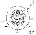
図2には、第2の実施形態によるディスプレースメントユニット10が示されている。これもまた、(軸11に)同軸の内側部分12およびこれと同軸の外側部分13を備える。内側部分12にはさらに内側通路14が設けられており、外側部分13には、互いに関係づけられて通路の組を形成する外側通路15が設けられている。通路のそれぞれの組には、ケージ17で案内される少なくとも1個のボール16が収容されている。 FIG. 2 shows a
ディスプレースメントユニット10は、外側部分13に6組の通路および4本のケージ案内路を備えて設計されており、図1に従った実施形態の図と異なる。さらに、ケージ案内路は内側部分12にも形成されている。 The
内側通路14および外側通路15によって形成される通路の組は、交互に個別に構成され、軸11の円周に組で互いに関係づけられている。ケージ17はケージ案内路18において案内され、それとケージ案内突出部19が係合する。それによってケージ案内突出部19およびケージ案内路18は、図2に従った実施形態では横断面が三角形で設計されている。しかし原理的に、ケージ案内路およびケージ案内突出部は適格な輪郭を備えることができ、例えば、山形、丸形などとすることができる。 The pairs of passages formed by the
さらに、図2に図示された実施形態の代替として、内側部分12および外側部分13によるケージ案内路18および対応するケージ案内突出部19は、本発明によれば、内側部分12だけ、または外側部分13だけに設けることができる。 Further, as an alternative to the embodiment illustrated in FIG. 2, the
このように、ディスプレースメントユニット10には、2本の隣り合うケージ案内路18の間に、組で構成された2本の外側通路15か、または1本の外側通路15だけのどちらかが存在する。それによって外側通路15およびケージ案内路18は全体として本質的に一様に外側部分13の外周に分布する。 Thus, in the
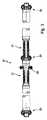
図3は、車両用の縦シャフトとして設計された縦シャフト20を縦断面で図示している。これはローリング調整装置として設計された2個のディスプレースメントユニット21および22を備える。ディファレンシャル側のその端およびギア側のその端で、ユニバーサルシャフト20はそれぞれ固定ジョイント23または24を備えて設計され、やはり固定ジョイントである中間ジョイント25を中央に備える。それによって2個のローリング調整装置21および22は中間ジョイント25と関係づけられ、それによって第2のローリング調整装置22の内側部分は中間ジョイント25の内レースと連結され、第1のローリング調整装置21の内側部分は中間ジョイント25の外レースと連結される。さらに、第1のローリング調整装置21の内レースは、例えば車両の底部に弾力的に懸架され得る中間ベアリング26に取り付けられている。 FIG. 3 shows, in a longitudinal section, a
2個のローラーバランス21および22の外側部分は、ギア側またはディファレンシャル側でジョイント23、24の外レースに取り付けられた管状シャフトと連結される。それによってユニバーサルシャフト20は、中間ジョイント25と関係づけられた3個の固定ジョイントおよび2個のローラーバランスによって形成される。動作時に、また特に組立中にユニバーサルシャフト20の軸方向に要求される変位通路は、ローラーバランス21および22によって受容されるにすぎない。 The outer portions of the two
Claims (14)
Translated fromJapanese外側通路がその内面の少なくとも区間ごとに設けられた管状外側部分と、
内部走行通路がその外面の少なくとも区間ごとに設けられると共に、前記外側部分内で軸方向に変位可能である内側部分と、
互いに関係づけられた外側通路および内側通路の組にそれぞれ配置されると共に、ケージ内で案内されてトルクを伝達するボールと、を備え、
前記外側部分および/または前記内側部分は、前記外側通路または前記内側通路の少なくとも数個の間に前記ケージを軸方向に案内するためのケージ案内路を備え、
前記ケージ案内路の数は、前記外側通路および前記内側通路によって形成される通路の前記組の数よりも少ないことを特徴とするディスプレースメントユニット。Displacement unit especially for universal shaft roller balance or displacement joint,
A tubular outer portion in which an outer passage is provided at least for each section of the inner surface;
An inner travel path is provided at least for each section of the outer surface, and an inner portion that is axially displaceable within the outer portion;
Each of which is disposed in a pair of an outer passage and an inner passage which are related to each other, and which is guided in a cage to transmit torque, and
The outer portion and / or the inner portion comprises a cage guideway for axially guiding the cage between at least some of the outer passage or the inner passage;
The displacement unit according to claim 1, wherein the number of the cage guide paths is smaller than the number of the sets of paths formed by the outer path and the inner path.
前記シャフト部分は中間ジョイントによって互いに連結されており、前記中間ジョイントから反対を向いたそれぞれの端においてギア側またはディファレンシャル側にジョイントを有しており、前記ギア側のジョイント、ディファレンシャル側のジョイントおよび中間ジョイントは、固定ジョイントとして、特に対向通路ジョイントとして設計されており、請求項9に記載のローラーバランスが2個設けられて前記中間ジョイントに対応して近くに取り付けられるユニバーサルシャフト。A universal shaft comprising at least two shaft portions each having a grooved tube,
The shaft portions are connected to each other by an intermediate joint, and each end facing away from the intermediate joint has a joint on the gear side or differential side, the gear side joint, the differential side joint and the intermediate side The universal shaft is designed as a fixed joint, in particular as an opposing passage joint, and is provided with two roller balances according to claim 9 and is mounted close to the intermediate joint.
Applications Claiming Priority (2)
| Application Number | Priority Date | Filing Date | Title |
|---|---|---|---|
| DE102006038697 | 2006-08-18 | ||
| PCT/DE2007/001442WO2008019668A1 (en) | 2006-08-18 | 2007-08-16 | Displacement unit and universal shaft comprising a displacement unit |
Publications (1)
| Publication Number | Publication Date |
|---|---|
| JP2010501058Atrue JP2010501058A (en) | 2010-01-14 |
Family
ID=38787595
Family Applications (1)
| Application Number | Title | Priority Date | Filing Date |
|---|---|---|---|
| JP2009524073APendingJP2010501058A (en) | 2006-08-18 | 2007-08-16 | Displacement unit and universal shaft provided with the displacement unit |
Country Status (7)
| Country | Link |
|---|---|
| US (1) | US8328649B2 (en) |
| JP (1) | JP2010501058A (en) |
| CN (1) | CN101506537B (en) |
| DE (1) | DE112007002502A5 (en) |
| FR (1) | FR2904989B1 (en) |
| IT (1) | ITMI20071673A1 (en) |
| WO (1) | WO2008019668A1 (en) |
Families Citing this family (10)
| Publication number | Priority date | Publication date | Assignee | Title |
|---|---|---|---|---|
| GB2444200B (en)* | 2005-09-27 | 2010-11-24 | Shaft Form Engineering Gmbh | Displacement unit and joint shaft comprising a displacement unit |
| EP2166239B1 (en)* | 2008-09-18 | 2012-04-18 | Centa-Antriebe Kirschey GmbH | Shaft assembly for transferring torque |
| US9958015B2 (en)* | 2013-09-27 | 2018-05-01 | Steering Solutions Ip Holding Corporation | Rolling-element telescoping shaft assembly |
| US20180065465A1 (en) | 2015-08-23 | 2018-03-08 | Arctic Cat Inc. | Off-Road Recreational Vehicle |
| US20170136874A1 (en) | 2015-08-23 | 2017-05-18 | Brian Harris | Off road vehicle |
| US11028883B2 (en) | 2017-11-13 | 2021-06-08 | Arctic Cat Inc. | Off-road recreational vehicle |
| FR3081197B1 (en)* | 2018-05-15 | 2021-12-10 | Safran Aircraft Engines | REDUCED FRICTION TORQUE TRANSMISSION DEVICE |
| KR102155835B1 (en)* | 2019-01-28 | 2020-09-14 | 이래에이엠에스 주식회사 | Plunging shaft and driveshaft assembly including same |
| US11712925B2 (en) | 2019-07-01 | 2023-08-01 | Textron Inc. | Axial plunging half-shaft assembly |
| CN114653072B (en)* | 2022-04-06 | 2023-12-12 | 广东派儿格智能科技有限公司 | Transmission device and toy car |
Citations (4)
| Publication number | Priority date | Publication date | Assignee | Title |
|---|---|---|---|---|
| JPH0297719A (en)* | 1988-03-17 | 1990-04-10 | Loehr & Bromkamp Gmbh | Synchronous sliding joint |
| JPH0428220U (en)* | 1990-06-29 | 1992-03-06 | ||
| US6241617B1 (en)* | 1998-07-10 | 2001-06-05 | Gkn Lobro Gmbh | Propeller shaft assembly for a motor vehicle especially a passenger car |
| JP2004060892A (en)* | 2002-07-25 | 2004-02-26 | Gkn Driveline Deutschland Gmbh | Longitudinal direction moving unit with braking roller |
Family Cites Families (8)
| Publication number | Priority date | Publication date | Assignee | Title |
|---|---|---|---|---|
| JP4034356B2 (en)* | 1996-10-31 | 2008-01-16 | ジー・ケー・エヌ・ドライブライン・インターナショナル・ゲゼルシャフト・ミット・ベシュレンクテル・ハフツング | Constant velocity universal joint |
| DE59909689D1 (en)* | 1998-01-19 | 2004-07-15 | Thyssenkrupp Presta Ag Eschen | DOUBLE JOINT FOR STEERING SHAFT IN MOTOR VEHICLES |
| US6059665A (en)* | 1998-06-08 | 2000-05-09 | The United States Of America As Represented By The Secretary Of The Air Force | Linear ball bearing drive shaft |
| DE19952245C2 (en) | 1998-12-05 | 2002-11-28 | Gkn Loebro Gmbh | telescopic shaft |
| CN2563352Y (en)* | 2002-07-22 | 2003-07-30 | 浙江万向机械有限公司 | Constant relocity universal joint with illiptic groove |
| DE10237169B4 (en)* | 2002-08-14 | 2006-08-03 | Shaft-Form-Engineering Gmbh | Plunging joint |
| DE20317344U1 (en)* | 2003-11-11 | 2004-01-08 | Dura Automotive Systems Reiche Gmbh & Co. Kg | Telescopic steering shaft |
| GB2444200B (en)* | 2005-09-27 | 2010-11-24 | Shaft Form Engineering Gmbh | Displacement unit and joint shaft comprising a displacement unit |
- 2007
- 2007-08-13ITIT001673Apatent/ITMI20071673A1/enunknown
- 2007-08-16CNCN2007800305915Apatent/CN101506537B/ennot_activeExpired - Fee Related
- 2007-08-16JPJP2009524073Apatent/JP2010501058A/enactivePending
- 2007-08-16USUS12/377,600patent/US8328649B2/ennot_activeExpired - Fee Related
- 2007-08-16WOPCT/DE2007/001442patent/WO2008019668A1/enactiveApplication Filing
- 2007-08-16DEDE112007002502Tpatent/DE112007002502A5/ennot_activeWithdrawn
- 2007-08-17FRFR0757085Apatent/FR2904989B1/ennot_activeExpired - Fee Related
Patent Citations (4)
| Publication number | Priority date | Publication date | Assignee | Title |
|---|---|---|---|---|
| JPH0297719A (en)* | 1988-03-17 | 1990-04-10 | Loehr & Bromkamp Gmbh | Synchronous sliding joint |
| JPH0428220U (en)* | 1990-06-29 | 1992-03-06 | ||
| US6241617B1 (en)* | 1998-07-10 | 2001-06-05 | Gkn Lobro Gmbh | Propeller shaft assembly for a motor vehicle especially a passenger car |
| JP2004060892A (en)* | 2002-07-25 | 2004-02-26 | Gkn Driveline Deutschland Gmbh | Longitudinal direction moving unit with braking roller |
Also Published As
| Publication number | Publication date |
|---|---|
| US8328649B2 (en) | 2012-12-11 |
| CN101506537A (en) | 2009-08-12 |
| FR2904989A1 (en) | 2008-02-22 |
| DE112007002502A5 (en) | 2009-07-23 |
| US20100227696A1 (en) | 2010-09-09 |
| WO2008019668A1 (en) | 2008-02-21 |
| FR2904989B1 (en) | 2014-02-14 |
| CN101506537B (en) | 2012-10-03 |
| ITMI20071673A1 (en) | 2008-02-19 |
Similar Documents
| Publication | Publication Date | Title |
|---|---|---|
| JP2010501058A (en) | Displacement unit and universal shaft provided with the displacement unit | |
| US7648419B2 (en) | Joint arrangement | |
| US10260569B2 (en) | Fixed-type constant velocity universal joint | |
| JP2000192937A (en) | Extensible shaft | |
| US8118683B2 (en) | Joint shaft and roller displacement UNIT THEREFOR | |
| US20170152895A1 (en) | Tripod type constant velocity universal joint | |
| US6942386B2 (en) | Roller bearing for linear movements | |
| KR20200093242A (en) | Plunging shaft and driveshaft assembly including same | |
| CN104919202B (en) | For transmitting the light construction connector of rotary motion | |
| JP4898811B2 (en) | Joint shaft with counter track joint with limited axial travel | |
| US20050049052A1 (en) | Longitudinal plunging unit | |
| US20150072795A1 (en) | Constant velocity joint | |
| EP1669622A4 (en) | Fixed type constant velocity universal joint | |
| JP2020046063A (en) | Tripod type constant velocity universal joint | |
| JP5631291B2 (en) | Counter track joint with track turning point | |
| US20060281564A1 (en) | Tripot joint retainer | |
| US20180363712A1 (en) | Ball cage for cross-groove type plunging and fixed constant velocity joints | |
| KR101504165B1 (en) | A universal joint for vehicle steering apparatus | |
| JP2007237800A (en) | Constant velocity joint for steering | |
| KR100695448B1 (en) | Slip joint with play compensation structure | |
| US20200070882A1 (en) | Intermediate Steering Shaft for a Motor Vehicle | |
| US20060166749A1 (en) | Sliding articulation | |
| US8262487B2 (en) | Ball joint | |
| KR101955190B1 (en) | Plunging type shaft unit of CVJ | |
| KR102151308B1 (en) | Tripod type constant velocity joint |
Legal Events
| Date | Code | Title | Description |
|---|---|---|---|
| A621 | Written request for application examination | Free format text:JAPANESE INTERMEDIATE CODE: A621 Effective date:20100302 | |
| A977 | Report on retrieval | Free format text:JAPANESE INTERMEDIATE CODE: A971007 Effective date:20120629 | |
| A131 | Notification of reasons for refusal | Free format text:JAPANESE INTERMEDIATE CODE: A131 Effective date:20120703 | |
| A521 | Request for written amendment filed | Free format text:JAPANESE INTERMEDIATE CODE: A523 Effective date:20121003 | |
| A131 | Notification of reasons for refusal | Free format text:JAPANESE INTERMEDIATE CODE: A131 Effective date:20130219 | |
| A02 | Decision of refusal | Free format text:JAPANESE INTERMEDIATE CODE: A02 Effective date:20130820 |