JP2010500914A - Push-off driver and method for inserting bone screws - Google Patents
Push-off driver and method for inserting bone screwsDownload PDFInfo
- Publication number
- JP2010500914A JP2010500914AJP2009524819AJP2009524819AJP2010500914AJP 2010500914 AJP2010500914 AJP 2010500914AJP 2009524819 AJP2009524819 AJP 2009524819AJP 2009524819 AJP2009524819 AJP 2009524819AJP 2010500914 AJP2010500914 AJP 2010500914A
- Authority
- JP
- Japan
- Prior art keywords
- driver
- sleeve
- bone screw
- screw
- release mechanism
- Prior art date
- Legal status (The legal status is an assumption and is not a legal conclusion. Google has not performed a legal analysis and makes no representation as to the accuracy of the status listed.)
- Granted
Links
- 210000000988bone and boneAnatomy0.000titleclaimsabstractdescription35
- 238000000034methodMethods0.000titleclaimsabstractdescription18
- 230000007246mechanismEffects0.000claimsabstractdescription51
- 238000007373indentationMethods0.000claimsdescription3
- 238000004891communicationMethods0.000claimsdescription2
- 230000004913activationEffects0.000claims1
- 238000003466weldingMethods0.000description6
- 239000000463materialSubstances0.000description3
- 230000006835compressionEffects0.000description2
- 238000007906compressionMethods0.000description2
- 238000004519manufacturing processMethods0.000description2
- 238000000429assemblyMethods0.000description1
- 230000000712assemblyEffects0.000description1
- 238000010586diagramMethods0.000description1
- 230000014509gene expressionEffects0.000description1
- 238000002513implantationMethods0.000description1
- 238000003780insertionMethods0.000description1
- 230000037431insertionEffects0.000description1
- 238000012986modificationMethods0.000description1
- 230000004048modificationEffects0.000description1
- 230000008569processEffects0.000description1
- 239000011435rockSubstances0.000description1
- 238000004904shorteningMethods0.000description1
- 238000006467substitution reactionMethods0.000description1
Images


Classifications
- A—HUMAN NECESSITIES
- A61—MEDICAL OR VETERINARY SCIENCE; HYGIENE
- A61B—DIAGNOSIS; SURGERY; IDENTIFICATION
- A61B17/00—Surgical instruments, devices or methods
- A61B17/56—Surgical instruments or methods for treatment of bones or joints; Devices specially adapted therefor
- A61B17/58—Surgical instruments or methods for treatment of bones or joints; Devices specially adapted therefor for osteosynthesis, e.g. bone plates, screws or setting implements
- A61B17/68—Internal fixation devices, including fasteners and spinal fixators, even if a part thereof projects from the skin
- A61B17/70—Spinal positioners or stabilisers, e.g. stabilisers comprising fluid filler in an implant
- A61B17/7074—Tools specially adapted for spinal fixation operations other than for bone removal or filler handling
- A61B17/7076—Tools specially adapted for spinal fixation operations other than for bone removal or filler handling for driving, positioning or assembling spinal clamps or bone anchors specially adapted for spinal fixation
- A61B17/7082—Tools specially adapted for spinal fixation operations other than for bone removal or filler handling for driving, positioning or assembling spinal clamps or bone anchors specially adapted for spinal fixation for driving, i.e. rotating, screws or screw parts specially adapted for spinal fixation, e.g. for driving polyaxial or tulip-headed screws
- A—HUMAN NECESSITIES
- A61—MEDICAL OR VETERINARY SCIENCE; HYGIENE
- A61B—DIAGNOSIS; SURGERY; IDENTIFICATION
- A61B17/00—Surgical instruments, devices or methods
- A61B17/56—Surgical instruments or methods for treatment of bones or joints; Devices specially adapted therefor
- A61B17/58—Surgical instruments or methods for treatment of bones or joints; Devices specially adapted therefor for osteosynthesis, e.g. bone plates, screws or setting implements
- A61B17/68—Internal fixation devices, including fasteners and spinal fixators, even if a part thereof projects from the skin
- A61B17/70—Spinal positioners or stabilisers, e.g. stabilisers comprising fluid filler in an implant
- A61B17/7001—Screws or hooks combined with longitudinal elements which do not contact vertebrae
- A61B17/7032—Screws or hooks with U-shaped head or back through which longitudinal rods pass
- A—HUMAN NECESSITIES
- A61—MEDICAL OR VETERINARY SCIENCE; HYGIENE
- A61B—DIAGNOSIS; SURGERY; IDENTIFICATION
- A61B17/00—Surgical instruments, devices or methods
- A61B17/56—Surgical instruments or methods for treatment of bones or joints; Devices specially adapted therefor
- A61B17/58—Surgical instruments or methods for treatment of bones or joints; Devices specially adapted therefor for osteosynthesis, e.g. bone plates, screws or setting implements
- A61B17/68—Internal fixation devices, including fasteners and spinal fixators, even if a part thereof projects from the skin
- A61B17/70—Spinal positioners or stabilisers, e.g. stabilisers comprising fluid filler in an implant
- A61B17/7001—Screws or hooks combined with longitudinal elements which do not contact vertebrae
- A61B17/7035—Screws or hooks, wherein a rod-clamping part and a bone-anchoring part can pivot relative to each other
- A—HUMAN NECESSITIES
- A61—MEDICAL OR VETERINARY SCIENCE; HYGIENE
- A61B—DIAGNOSIS; SURGERY; IDENTIFICATION
- A61B17/00—Surgical instruments, devices or methods
- A61B17/56—Surgical instruments or methods for treatment of bones or joints; Devices specially adapted therefor
- A61B17/58—Surgical instruments or methods for treatment of bones or joints; Devices specially adapted therefor for osteosynthesis, e.g. bone plates, screws or setting implements
- A61B17/68—Internal fixation devices, including fasteners and spinal fixators, even if a part thereof projects from the skin
- A61B17/84—Fasteners therefor or fasteners being internal fixation devices
- A61B17/86—Pins or screws or threaded wires; nuts therefor
- A61B17/8605—Heads, i.e. proximal ends projecting from bone
- A61B17/861—Heads, i.e. proximal ends projecting from bone specially shaped for gripping driver
- A61B17/8615—Heads, i.e. proximal ends projecting from bone specially shaped for gripping driver at the central region of the screw head
- A—HUMAN NECESSITIES
- A61—MEDICAL OR VETERINARY SCIENCE; HYGIENE
- A61B—DIAGNOSIS; SURGERY; IDENTIFICATION
- A61B17/00—Surgical instruments, devices or methods
- A61B17/56—Surgical instruments or methods for treatment of bones or joints; Devices specially adapted therefor
- A61B17/58—Surgical instruments or methods for treatment of bones or joints; Devices specially adapted therefor for osteosynthesis, e.g. bone plates, screws or setting implements
- A61B17/68—Internal fixation devices, including fasteners and spinal fixators, even if a part thereof projects from the skin
- A61B17/84—Fasteners therefor or fasteners being internal fixation devices
- A61B17/86—Pins or screws or threaded wires; nuts therefor
- A61B17/8605—Heads, i.e. proximal ends projecting from bone
- A61B17/861—Heads, i.e. proximal ends projecting from bone specially shaped for gripping driver
- A61B17/862—Heads, i.e. proximal ends projecting from bone specially shaped for gripping driver at the periphery of the screw head
- A—HUMAN NECESSITIES
- A61—MEDICAL OR VETERINARY SCIENCE; HYGIENE
- A61B—DIAGNOSIS; SURGERY; IDENTIFICATION
- A61B17/00—Surgical instruments, devices or methods
- A61B17/56—Surgical instruments or methods for treatment of bones or joints; Devices specially adapted therefor
- A61B17/58—Surgical instruments or methods for treatment of bones or joints; Devices specially adapted therefor for osteosynthesis, e.g. bone plates, screws or setting implements
- A61B17/88—Osteosynthesis instruments; Methods or means for implanting or extracting internal or external fixation devices
- A61B17/8875—Screwdrivers, spanners or wrenches
- A61B17/8877—Screwdrivers, spanners or wrenches characterised by the cross-section of the driver bit
- A61B17/888—Screwdrivers, spanners or wrenches characterised by the cross-section of the driver bit the driver bit acting on the central region of the screw head
- A—HUMAN NECESSITIES
- A61—MEDICAL OR VETERINARY SCIENCE; HYGIENE
- A61B—DIAGNOSIS; SURGERY; IDENTIFICATION
- A61B17/00—Surgical instruments, devices or methods
- A61B17/56—Surgical instruments or methods for treatment of bones or joints; Devices specially adapted therefor
- A61B17/58—Surgical instruments or methods for treatment of bones or joints; Devices specially adapted therefor for osteosynthesis, e.g. bone plates, screws or setting implements
- A61B17/88—Osteosynthesis instruments; Methods or means for implanting or extracting internal or external fixation devices
- A61B17/8875—Screwdrivers, spanners or wrenches
- A61B17/8877—Screwdrivers, spanners or wrenches characterised by the cross-section of the driver bit
- A61B17/8883—Screwdrivers, spanners or wrenches characterised by the cross-section of the driver bit the driver bit acting on the periphery of the screw head
- A—HUMAN NECESSITIES
- A61—MEDICAL OR VETERINARY SCIENCE; HYGIENE
- A61B—DIAGNOSIS; SURGERY; IDENTIFICATION
- A61B17/00—Surgical instruments, devices or methods
- A61B17/56—Surgical instruments or methods for treatment of bones or joints; Devices specially adapted therefor
- A61B17/58—Surgical instruments or methods for treatment of bones or joints; Devices specially adapted therefor for osteosynthesis, e.g. bone plates, screws or setting implements
- A61B17/88—Osteosynthesis instruments; Methods or means for implanting or extracting internal or external fixation devices
- A61B17/8875—Screwdrivers, spanners or wrenches
- A61B17/8886—Screwdrivers, spanners or wrenches holding the screw head
- B—PERFORMING OPERATIONS; TRANSPORTING
- B25—HAND TOOLS; PORTABLE POWER-DRIVEN TOOLS; MANIPULATORS
- B25B—TOOLS OR BENCH DEVICES NOT OTHERWISE PROVIDED FOR, FOR FASTENING, CONNECTING, DISENGAGING OR HOLDING
- B25B23/00—Details of, or accessories for, spanners, wrenches, screwdrivers
- B25B23/0007—Connections or joints between tool parts
- B25B23/0035—Connection means between socket or screwdriver bit and tool
- B—PERFORMING OPERATIONS; TRANSPORTING
- B25—HAND TOOLS; PORTABLE POWER-DRIVEN TOOLS; MANIPULATORS
- B25B—TOOLS OR BENCH DEVICES NOT OTHERWISE PROVIDED FOR, FOR FASTENING, CONNECTING, DISENGAGING OR HOLDING
- B25B23/00—Details of, or accessories for, spanners, wrenches, screwdrivers
- B25B23/0007—Connections or joints between tool parts
- B25B23/0042—Connection means between screwdriver handle and screwdriver shaft
- B—PERFORMING OPERATIONS; TRANSPORTING
- B25—HAND TOOLS; PORTABLE POWER-DRIVEN TOOLS; MANIPULATORS
- B25B—TOOLS OR BENCH DEVICES NOT OTHERWISE PROVIDED FOR, FOR FASTENING, CONNECTING, DISENGAGING OR HOLDING
- B25B23/00—Details of, or accessories for, spanners, wrenches, screwdrivers
- B25B23/02—Arrangements for handling screws or nuts
- B25B23/08—Arrangements for handling screws or nuts for holding or positioning screw or nut prior to or during its rotation
- B25B23/10—Arrangements for handling screws or nuts for holding or positioning screw or nut prior to or during its rotation using mechanical gripping means
- B25B23/101—Arrangements for handling screws or nuts for holding or positioning screw or nut prior to or during its rotation using mechanical gripping means for hand-driven screw-drivers
- A—HUMAN NECESSITIES
- A61—MEDICAL OR VETERINARY SCIENCE; HYGIENE
- A61B—DIAGNOSIS; SURGERY; IDENTIFICATION
- A61B17/00—Surgical instruments, devices or methods
- A61B2017/00367—Details of actuation of instruments, e.g. relations between pushing buttons, or the like, and activation of the tool, working tip, or the like
- A61B2017/00407—Ratchet means
- Y—GENERAL TAGGING OF NEW TECHNOLOGICAL DEVELOPMENTS; GENERAL TAGGING OF CROSS-SECTIONAL TECHNOLOGIES SPANNING OVER SEVERAL SECTIONS OF THE IPC; TECHNICAL SUBJECTS COVERED BY FORMER USPC CROSS-REFERENCE ART COLLECTIONS [XRACs] AND DIGESTS
- Y10—TECHNICAL SUBJECTS COVERED BY FORMER USPC
- Y10S—TECHNICAL SUBJECTS COVERED BY FORMER USPC CROSS-REFERENCE ART COLLECTIONS [XRACs] AND DIGESTS
- Y10S606/00—Surgery
- Y10S606/916—Tool for installing or removing orthopedic fastener
Landscapes
- Health & Medical Sciences (AREA)
- Orthopedic Medicine & Surgery (AREA)
- Surgery (AREA)
- Life Sciences & Earth Sciences (AREA)
- Neurology (AREA)
- Engineering & Computer Science (AREA)
- Medical Informatics (AREA)
- Heart & Thoracic Surgery (AREA)
- Biomedical Technology (AREA)
- Molecular Biology (AREA)
- Animal Behavior & Ethology (AREA)
- General Health & Medical Sciences (AREA)
- Public Health (AREA)
- Veterinary Medicine (AREA)
- Nuclear Medicine, Radiotherapy & Molecular Imaging (AREA)
- Mechanical Engineering (AREA)
- Surgical Instruments (AREA)
Abstract
Translated fromJapaneseDescription
Translated fromJapanese本発明は、患者にねじを挿入するためのデバイス及び方法に関する。 The present invention relates to a device and method for inserting a screw into a patient.
ねじ、例えば多軸ねじを挿入するドライバの使用は、当該技術で知られている。実際には、多軸ねじドライバが、多軸ねじに連結し、埋め込み処置の間、多軸ねじを回して患者に入れる。 The use of a screwdriver, for example a screwdriver to insert a multiaxial screw, is known in the art. In practice, a polyaxial screw driver is coupled to the polyaxial screw and turns the polyaxial screw into the patient during the implantation procedure.
過去には、多軸ねじ用のドライバは成功したものの、多数の困難ももたらした。その問題の一つは、挿入の後、ドライバを多軸ねじから取り外す間に起こった。従来技術のドライバでは、ねじを挿入した後、ドライバがねじの凹み内に付着する。この現象は、当該技術で「スティッキング」と呼ばれる。ドライバが多軸ねじに付着すると、ドライバをねじから外すのが困難になり、外科医は、ドライバをねじから外すために、ドライバを揺さぶらなければならないかもしれない。これは、外科医に別の困難を生じさせる。従って、ドライバのユーザに、より柔軟性を可能にし、且つ患者に対するリスクを減らせる、多軸ねじから容易に取り外せるドライバのニーズが存在する。本発明は、他のニーズと共に、上記ニーズを満たす。 In the past, drivers for multi-axis screws have been successful, but have also presented a number of difficulties. One of the problems occurred after insertion, while removing the driver from the polyaxial screw. In prior art drivers, after the screw is inserted, the driver adheres within the recess of the screw. This phenomenon is called “sticking” in the art. If the driver attaches to the polyaxial screw, it becomes difficult to remove the driver from the screw, and the surgeon may have to rock the driver to remove the driver from the screw. This creates another difficulty for the surgeon. Accordingly, there is a need for a driver that can be easily removed from a polyaxial screw that allows the user of the driver more flexibility and reduces risk to the patient. The present invention meets the above needs as well as other needs.
上記の説明、及び骨ねじ用のドライバの分野の欠点の観点から、以下で説明するねじを患者に挿入する装置及び方法がこのような欠点を克服しようとする。一実施形態では、押し離しドライバ(例えば、後頸押し離しドライバ)、及び(例えば、脊椎の後方固定のための)患者にねじを挿入する方法を開示する。ドライバは、ハンドルと、遠位端で骨ねじに連結できるドライバスリーブと、ドライバスリーブ内で解放可能に移動でき、骨ねじを回すためのドライブ構造を有する内側ドライバと、内側ドライバに対してドライバスリーブを係止し、又は係止を外すための解放機構とを含む。解放機構の操作は、内側ドライバからねじを押し離す。 In view of the above description and the shortcomings in the field of drivers for bone screws, the devices and methods for inserting the screw described below attempt to overcome such shortcomings. In one embodiment, a push-off driver (eg, posterior cervical push-off driver) and a method of inserting a screw into a patient (eg, for posterior fixation of the spine) are disclosed. The driver includes a handle, a driver sleeve that can be coupled to the bone screw at the distal end, an inner driver that is releasably movable within the driver sleeve and has a drive structure for turning the bone screw, and a driver sleeve relative to the inner driver And a release mechanism for unlocking. Operation of the release mechanism pushes the screw away from the inner driver.
一実施形態では、押し離しドライバは、ハンドルと、一つ又はそれ以上の凹みを有する内側ドライバと、ボタン機構及び一つ又はそれ以上の球体を有するねじ山付きドライバスリーブを有するボタン押し離しドライバであってもよく、解放機構の作動は、球体を凹みから解放する。ボタン機構は、ボタン、内側ドライバ、及び圧縮バネを含んでもよい。内側ドライバは、遠位端に、ねじヘッドの凹み又は構造に対応するドライブ機構を有する。さらに、内側スリーブは、球体が着座する、一つ又はそれ以上の孔を含むことができる。 In one embodiment, the push driver is a button push driver having a handle, an inner driver having one or more indentations, and a threaded driver sleeve having a button mechanism and one or more spheres. There may be an actuation of the release mechanism to release the sphere from the recess. The button mechanism may include a button, an inner driver, and a compression spring. The inner driver has a drive mechanism at the distal end corresponding to the recess or structure of the screw head. Furthermore, the inner sleeve can include one or more holes in which the spheres are seated.
一実施形態によれば、スクリュードライバを骨ねじから解放する方法は、ハンドルと、一つ又はそれ以上の凹みを有する内側ドライバと、ボタン機構を有するねじ山付きドライバスリーブを有する押し離しドライバの組み立てを含む。外側スリーブの遠位端に多軸ねじを螺合させて多軸ねじを押し離しドライバに取り付けると、内側ドライバの遠位端から垂直に突出するクロスピンによって、ねじを好ましくはしっかりと内側ドライバに連結し、多軸ねじを患者に挿入する。多軸ねじを押し離しドライバに取り付けるとき、ねじ山付きドライバスリーブは、内側ドライバに関して進み、一つ又はそれ以上の球体を、内側ドライバに配置された一つ又はそれ以上の凹みに落とし込ませる。次いで、外側スリーブを多軸ねじから取り外すことによって、押し離しドライバを多軸ねじから取り外し、一つ又はそれ以上の球体が、一つ又はそれ以上の凹みと係合して、ねじ山付きドライバが遠位方向に移動するのを防止し、骨ねじが内側ドライバから外れるのを防ぐ。一実施形態では、骨ねじを押し離しドライバから外すことは、ねじ山付きドライバスリーブを多軸ねじから取り外して内側ドライバの凹み内の球体を、凹みの前面に対して後退させ、ねじ山付きドライバスリーブがさらに遠位方向に移動するのを防止し、さらに、ねじ山付きドライバスリーブの多軸ねじからの連続した取り外しは、ねじ山付きドライバが、多軸ねじを内側ドライバから押し離し、且つ解放する。 According to one embodiment, a method of releasing a screwdriver from a bone screw includes assembling a push-off driver having a handle, an inner driver having one or more recesses, and a threaded driver sleeve having a button mechanism. including. Screw the polyaxial screw into the distal end of the outer sleeve, push the polyaxial screw apart and attach it to the driver, then connect the screw to the inner driver, preferably firmly, with a cross pin protruding vertically from the distal end of the inner driver And inserting a multi-axis screw into the patient. When pushing the polyaxial screw apart and attaching it to the driver, the threaded driver sleeve advances with respect to the inner driver and causes one or more spheres to drop into one or more recesses located in the inner driver. The screwdriver is then removed from the polyaxial screw by removing the outer sleeve from the polyaxial screw, and the one or more spheres engage with the one or more recesses so that the threaded screwdriver is Prevents distal movement and prevents the bone screw from detaching from the inner driver. In one embodiment, pushing the bone screw away from the driver removes the threaded driver sleeve from the polyaxial screw and retracts the sphere in the inner driver recess against the front surface of the recess, Preventing the sleeve from moving further in the distal direction, and the continuous removal of the threaded driver sleeve from the polyaxial screw allows the threaded driver to push the polyaxial screw away from the inner driver and release To do.
他の実施形態では、押し離しドライバは、ハンドルと、ねじに取り付けるための遠位端を有する外側スリーブと、遠位端に、ねじヘッドの凹みに対応するドライブ機構を有する内側ドライバと、内側ドライバの遠位端から垂直に突出するクロスピンを含む。ドライバは、外側スリーブの近位端に螺合された上刻み付き部分をさらに含み、刻み付き部分を取り外すことにより、外側スリーブが、ねじを内側ドライバから解放させる。 In other embodiments, the push-off driver includes a handle, an outer sleeve having a distal end for attachment to the screw, an inner driver having a drive mechanism at the distal end corresponding to the recess of the screw head, and an inner driver. Including a cross pin projecting vertically from the distal end thereof. The driver further includes an upper knurled portion threaded onto the proximal end of the outer sleeve, and removing the knurled portion causes the outer sleeve to release the screw from the inner driver.
他の実施形態において、ねじを挿入するための押し離しドライバは、ハンドルと、ねじに取り付けられるための遠位端を有する外側スリーブと、内側ドライバを含み、内側ドライバの遠位端に、ねじヘッドの凹みに対応するドライブ機構を有する。一実施形態によれば、ドライバは、ラチェット機構、及び外側スリーブの近位端に螺合された刻み付き部分を含み、刻み付き部分の取り外しにより、外側スリーブが、内側ドライバからねじを解放させる。 In another embodiment, a push-off driver for inserting a screw includes a handle, an outer sleeve having a distal end to be attached to the screw, and an inner driver, the screw head at the distal end of the inner driver. And a drive mechanism corresponding to the dents. According to one embodiment, the driver includes a ratchet mechanism and a knurled portion threaded into the proximal end of the outer sleeve, with removal of the knurled portion causing the outer sleeve to release the screw from the inner driver.
本発明は、同様の参照記号が同様の構成部品を示す、以下の図面を参照することによって、よりよく分かる。図面は、一つ又は他の特徴との組み合わせで使用することができる幾つかの特徴を示すための例示に過ぎず、本発明は、示される実施形態に限定されるべきではない。 The invention can be better understood by reference to the following drawings, in which like reference numerals indicate like components. The drawings are only exemplary to illustrate some features that may be used in combination with one or other features, and the invention should not be limited to the illustrated embodiments.
骨ねじを挿入するための押し離しドライバ及び押し離し方法をここに記述し、且つ説明する。説明の目的のために、以下の記述では、発明の完全な理解を提供するための或る寸法、材料、及び構成を示す。しかしながら、本発明は、これらの具体的な詳細なしに実施できることは当業者には明らかである。或る場合は、本発明を分かりにくくしないように、周知の特徴を省略し、又は単純化する。加えて、詳細な説明では、押し離しドライバと、挿入されるべきねじを一般的に、多軸ねじドライバ及び多軸ねじとして説明するが、本発明の特徴は、どんな骨ねじを使用しても実行できることを理解すべきである。 A push-off driver and push-out method for inserting a bone screw will now be described and explained. For purposes of explanation, the following description sets forth certain dimensions, materials, and configurations to provide a thorough understanding of the invention. However, it will be apparent to those skilled in the art that the present invention may be practiced without these specific details. In some instances, well known features are omitted or simplified so as not to obscure the present invention. In addition, although the detailed description describes the push-off driver and the screw to be inserted generally as a multi-axis screw driver and a multi-axis screw, the features of the present invention are not limited to using any bone screw. It should be understood that it can be done.
幾つかの実施形態を、同様の参照番号が同様の構成部品を示す、上述の図面を参照して説明する。明細書での「一実施形態」又は「実施形態」のような表現への言及は、実施形態と関連して説明する特定部分、構造、又は特徴は、少なくとも一実施形態に含まれることを意味することに気付くべきである。明細書の各所にあるの様相、又は「一実施形態において」のような表現は、必ずしも同じ実施形態を参照しているのではないが、同じ実施形態を参照していてもよい。 Several embodiments will be described with reference to the above-mentioned drawings, wherein like reference numerals indicate like components. References to expressions in the specification such as “one embodiment” or “an embodiment” mean that a particular part, structure, or feature described in connection with the embodiment is included in at least one embodiment. You should notice that you do. References to aspects throughout the specification, or “in one embodiment”, do not necessarily refer to the same embodiment, but may refer to the same embodiment.
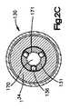
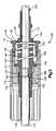
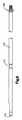
図1A−1Cで、より詳細に図2−11で分かるように、ねじ2を挿入するために使用される押し離しドライバ100の実施形態を示す。本実施形態では、ねじ2は、多軸ねじであるが、多軸ねじ以外のねじを、ここに説明する押し離しドライバとともに使用してもよい。以下でより詳細に説明するように、押し離しドライバ100は、ハンドル160、バネ付勢のねじ山付きドライバスリーブ130及び内側ドライバ170を含む。押し離しドライバ100は、「スティッキング」現象を減らしながら、多軸ねじ2を患者にねじ込むために使用される。 1A-1C show an embodiment of a push-off
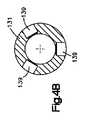
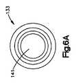
バネ付勢のねじ山付きドライバ130は、内側ドライバスリーブ131(図4に示す)を含むボタン機構109と、ボタン132と、バネ135と、外側スリーブ133(図6A−Bに示す)と、トリガハウジング134を含む。トリガハウジング134は、内側スリーブ131、外側スリーブ133、バネ135、及びボタン132を包囲し、且つこれらと同軸である。トリガハウジング134の近位端145は、内側スリーブ131の近位端138に固定される。トリガハウジング134の遠位端144は、外側スリーブ133を受け入れるキャビティ147を有する。 A spring
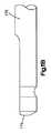
内側スリーブ131は、長手方向軸線に沿って延びるチャンネル186を有する、実質的に中空の細長いチューブであり、長手方向軸線と直角な長さに沿って、一つ又はそれ以上の孔139を有し、一つ又はそれ以上の球体136がその孔に着座することができる。カラー140が、孔139の遠位で、その長さに沿って配置され、カラーは、カラーの近くの領域、及び内側スリーブ131の他の領域の直径を越えて円周方向に突出する。ボタン132は、円筒部材(図5)であり、長さ方向に沿って延びるキャビティ150を有し、内側スリーブ131の内側に、且つ内側スリーブ131の長手方向軸線に沿って同軸に配置される。ボタン132は、同様に、カラー140の遠位で、内側スリーブ131の長手方向軸に沿って同軸に配置されたバネ135と連絡することによってボタン機構109の中へバネ付勢される。
外側スリーブ133(図6A−Bに示す)は、外側スリーブ133の長さ全体に延びるキャビティ141を有する。図3に示すように外側スリーブ133の遠位端142は、ボタン132の近位端148と重なり、且つ近位端148に連結される。バネ135は、外側スリーブ133のキャビティ141、及びボタン132のキャビティ150内に収容される。バネ135の近位端153は、内側スリーブ131のカラー140に当接し、バネ135の遠位端154は、ボタン132の遠位端158に当接する。かくしてカラーは、外側スリーブ133がトリガハウジング134から滑り出るのを防止し、バネ135を縮ませる。ボタン132と外側スリーブ133の重なり部は、圧縮バネ135が内側スリーブ131に組み付けられた後に、例えば溶接によって固定される。キャビティ141の直径は、外側スリーブの長さに沿って変化してもよい。 The outer sleeve 133 (shown in FIGS. 6A-B) has a
トリガハウジング134は、外側スリーブ133に隣接し、且つ外側スリーブ133と連絡した中空のチューブである。ボタン機構109を組み立てる際、内側スリーブ131は、外側スリーブ133のキャビティ141を通して挿入され、外側スリーブ133の遠位端143を通り越して延びる。外側スリーブ133の近位端143から突出する、内側スリーブ131の近位端138は、例えば127で、螺合及び/又は溶接によって、トリガハウジング134の近位端145に固定される。 The
内側ドライバ170は、内側ドライバ170の遠位端177にドライブ179及びクロスピン180を、近位端175の近くに一つ又はそれ以上の凹み171を含む細長いチューブである。ドライブ179は、六角、異形キー、プラス、T15、又はねじ2を回すためのどんな他の形体のような、任意の数の異なる種類のドライブのうちの一つである。内側ドライバ170は、詳細は後述するように、押し離しドライバ100が組み立てられたときに、近位端175で、ねじ山付きドライバスリーブ130に嵌り込むことができるように構成される。
今、押し離しドライバの種々の部品の好ましい寸法を説明する。ここで説明する寸法は、例示に過ぎず、それにより本発明が限定されないことを理解すべきである。内側ドライバスリーブの近位端138からねじ山付き遠位端137の先端までは、好ましくは長さが約160mm乃至約200であり、より好ましくは長さが185.5mmである。ねじ山付き遠位端137の近くの内側スリーブ131の近位端の直径は、約5.9mmであり、遠位端137の直径は、約8.5mmであるが、他の寸法の考えられる。上で説明したように、複数の孔139の遠位にカラー140があり、カラーは、好ましくは10mm乃至15mm、最も好ましくは約13mmの直径を有するが、他の寸法も適当である。カラー140の近位の、内側スリーブ131の近位端の直径は、好ましくは6mm乃至9.5mm、最も好ましくは約8.1mmであるが、他の寸法も適当である。 The preferred dimensions of the various parts of the push-off driver will now be described. It should be understood that the dimensions described herein are exemplary only and do not limit the invention. The length from the
好ましくは外側スリーブ133は、長さ約15mm乃至約25mm、より好ましくは約19.2mmであり、上述したように全長に亘って延びるキャビティ141を有する。一実施形態では、キャビティ141の直径は、外側スリーブ133の長さに沿って変化し、このため、外側スリーブ133の遠位端の近くの直径は約13.3mm、外側スリーブ133の中間部分の近くの直径は約9.6mm、外側スリーブ133の近位端でのキャビティ141の直径は約8.2mmであるが、他の寸法も考えられる。 Preferably, the
好ましくはボタン132は、長さ約9.25mmであり、ボタン132の長さに亘って延びる直径約12mmのキャビティ150を有するが、他の寸法も適当である。好ましくはボタン132の遠位端149でのキャビティ150への開口151は、カラー140の遠位で内側スリーブ131の近位端138に、同軸に嵌るように約9.2mmの直径を有する。好ましくはトリガハウジング134は、長さ約30.5mmであり、これにキャビティ147を有し、キャビティ147は、これに外側スリーブ133が嵌ることができる約14.63mmの内径を有する。加えて、好ましくは内側ドライバ170は、長さが約200mm乃至約240mm、より好ましくは長さが約220.5mmである。 Preferably, the
今、ドライバ100の組み立て及び操作について詳述する。ドライバ100を組み立てるために、バネ付勢のドライバ130、より具体的には内側スリーブ131を、内側ドライバ170の近位端175の頂部に配置する。内側ドライバ170は、内側ドライバ170の近位端175が内側スリーブ131の近位端138の外に延びるまで、内側スリーブ131のチャンネル186の中を滑る。次いで、内側ドライバとハンドルを螺合及び/又は溶接し、又は他の取り付け手段を用いて内側ドライバ170を、ハンドル160に固定する。上述したように、内側ドライバ170は、その遠位端177に、内側ドライバ170に対する多軸ヘッドの回転を防止するために使用されるクロスピン/だぼ180、又は他のどんな形態を含んでいてもよい。内側ドライバが内側スリーブ131のチャンネル186の中を滑ると、内側スリーブ131の遠位端は、ついには、内側ドライバ170に取り付けられたクロスピン180に付き当たる。内側ドライバ170は、図1Dで分かるように、その遠位端にドライブ179を、近位端近くに凹み171を含む。 Now, the assembly and operation of the
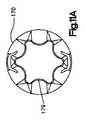
次いで、ねじ山付き部分137を用いてねじ山付きドライバスリーブ130を、多軸ねじ2のヘッドに螺合させる。次いで、多軸ねじ2とねじ山付きドライバスリーブ130を一緒に引き、内側ドライバ170のだぼ180が、多軸ねじ2に係合して、ドライバ100に連結するときに多軸ねじ2の回転又はトグルを防止する。ドライバ100をねじ2に螺合させる前に、ドライバ100のユーザが、ボタン132を押し下げ、外側スリーブ133を近位方向に移動させ、球体136を孔139に沿って自由に移動させることができる。一実施形態では、図2Cに示すように3つの孔139、及び3つの球体136があるが、より多くの数、又はより少ない数を使用してもよい。加えて、球体136以外の形状を使用することもできる。より具体的には、押し下げボタン132は、外側スリーブ133を近位方向に移動させるから、球体136が孔139を越えて突出するのに十分な空間を有する。この方法で、球体136が、孔139の中へ移動できるので、球体136は、もはやチャンネル186内に突出しない。一旦、ねじ2をドライバスリーブ130に螺合させ、ねじ2をドライバ170としっかり係合させると、ボタン132は、係合が外れ又は飛び出し、これにより球体136を内側ドライバ170の凹み171内に落ち込ませ、ドライバスリーブ130と内側ドライバ170を共に係止する。一旦、取り付けられると、ドライブのユーザ(例えば、外科医)は、多軸ねじ2を患者の骨に固定することができる。 The threaded
ねじが患者の骨に挿入された後、ユーザがドライバ100を多軸ねじ2から外したく、彼又は彼女は、多軸ねじ2からねじ山付きドライバスリーブ130を取り外すことから始める。従来のシステムでは螺合を外すときに、ドライバは多軸ねじ2の凹み内に「付着する(stick)」傾向があった。この「スティッキング」現象を無くすために、ねじ山付きドライバスリーブ130が、多軸ねじ2から取り外されるとき、先に内側ドライバ170の凹み171に落とし込まれていた、ねじ山付きドライバスリーブ130の球体136が、凹み171の始点に向かって「後退」する。これは、ねじ山付きドライバスリーブ130が更に(近位方向に)後退するのを防止する。多軸ねじ2から螺合が外されるとき、もはやねじ山付きドライバスリーブ130が後退することができないので、ねじ山付きドライバスリーブ130は、多軸ねじ2が患者にしっかりと埋め込まれているので、多軸ねじ2を内側ドライバ170から追い出し、これにより、ドライバ100を取り外すときに、内側ドライバ170が多軸ねじ2の凹み内に付着する可能性を減らす。 After the screw has been inserted into the patient's bone, the user wishes to remove the
内側ドライバ170の凹み171に係合する球体136を使用することに対する、種々の変形の方法がある。一つのこのような方法は、図10に示すように、バネ156を使用して、外側スリーブ133内にバネ付勢された一つ又はそれ以上のピン155を使用する。ピン155が凹み171にあるのを示す図1Dに示すように、バネ付勢されたピン155は、上述の球体136と同じ機能を実現する。換言すれば、この実施形態では、バネ156を使用して、ピン155を外側スリーブ133の近位端の近くに保持し、ピン155は、図1Dに示すようにボタン132が係合したときに凹み171の中に落ち込む。取り外すとき、ピン155は、凹み171に向かって後退し、先に説明した実施形態で球体136が凹み171に向かって後退したのと同様の方法で、付着を減らす。ピンを凹み171から解放するために、ボタンを解放し、ピン155がバネ156に向かって凹み171から取り外される。 There are various variations on the use of the
上述の実施形態は、球体とバネ付勢のピンを使用する観点で説明したが、或る実施形態では、内側ドライバ170の凹みに係合する他の摺動部材を使用することができることに気付くべきである。変形として、凹みを、ボタン機構109の一部、且つ球体136又は他の摺動部材が内側ドライバ170の一部とすることもできる。 While the above embodiments have been described in terms of using spheres and spring biased pins, it will be noted that in some embodiments, other sliding members that engage the recesses of the
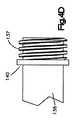
図12A−Cは、押し離しドライバの他の実施形態、具体的にはねじ山付き押し離しドライバ1200を示す。ねじ山付き押し離しドライバ1200は、ハンドル1210と、上刻み付き部分1220と、多軸ねじヘッドの凹み又は他の構造に対応するドライブ機構を有する内側ドライバ1270と、クロスピン1280と、遠位端にねじ山1235を有する外側スリーブ1230とを含む。上刻み付き部分1220と外側スリーブ1230は、上述の実施形態のボタン機構109と同様に、一緒に機能して、内側ドライバ1270と多軸ねじ2との間での「スティッキング」を減らす。一実施形態では、上刻み付き部分1220は、外側スリーブ1230の近位端に螺合される。 12A-C illustrate another embodiment of a push-off driver, specifically a threaded push-off driver 1200. FIG. A threaded push-off driver 1200 includes a
図12A−Cに示すねじ山付き押し離しドライバの操作は、2段プロセスで行われる。先ず、外側スリーブ1230を内側スリーブ1270上に配置することによって押し離しドライバ1200を組み立てる。次いで、上刻み付き部分1220を、外側スリーブ1230の近位端1225内に螺合させ、ハンドル1210の遠位部1215に固定する。上刻み付き部分1220を、2つの構成部品を互いに溶接し、又はねじ留めすることを含む、公知の方法を使用してハンドル1210に取り付けることができる。内側ドライバ1270も、2つの部品を互いに螺合及び/又は溶接、或いは他の取り付け手段を使用して、ハンドル1210に固定する。 The operation of the threaded push-off driver shown in FIGS. 12A-C is performed in a two-stage process. First, the push-off driver 1200 is assembled by placing the
ドライバ1200を組み立てた後、上述の実施形態で多軸ねじ2を外側スリーブ130に螺合させ、且つ内側ドライバ170に係止させる方法と同様の方法で、多軸ねじ2を外側スリーブ1230に螺合させ、且つ内側ドライバ1270に係止する。一旦、骨ねじが埋め込まれ、ユーザ(外科医)がドライバを取り外したければ、ユーザは、外側スリーブ130を骨ねじから取り外し始める。スリーブ1230が多軸ねじ2から取り外されたとき、「スティッキング」が伝統的に起きていたのはこのときである。ユーザが「スティッキング」が起きているのを観察したならば、ユーザは、上刻み部分1220を外側スリーブ1230から取り外す。これは、ユーザが外側スリーブ1230をしっかり保持し、上刻み部分1220がハンドル1210に向かって近位方向に移動するように、上刻み部分1220を外側スリーブ1230から取り外すことによって達成される。これは、外側スリーブ1230を入れ子にすること、及び上刻み部分1220が外側スリーブ1230の延長体になるため、内側ドライバ1270を効果的に短くすることの目的に適う。外側スリーブ1230をねじからさらに取り外すと、内側ドライバ1270をねじ2から分離する。 After assembling the driver 1200, the multiaxial screw 2 is screwed to the
上刻み部分1220を近位方向に移動させると、上刻み部分1220は、ハンドルの遠位部分1215と接触し、外側スリーブ1230から取り外されると、もはや近位方向に進むことができない。上刻み部分1220が近位方向に進むことができないから、上刻み部分1220を外側スリーブ1230から取り外し続けると、その代わり外側スリーブ1230を遠位方向に押し、外側スリーブ1230は、多軸ねじ2を遠位方向に押し、これにより、内側ドライバ1270を多軸ねじ2の凹みから取り外し、「スティッキング」現象を減らす。この実施形態では、上刻み部分1220が内側ドライバ1270を多軸ねじ2から押し離すとき、外側スリーブ1230は、多軸ねじに螺合したままでもよいし、上刻み部分1220が外側スリーブ1230から取り外される前に多軸ねじ2から取り外されてもよい。何れの筋書きでも、上刻み部分1220の取り外しにより、内側ドライバ1270を多軸ねじ2から押し離す。 When the upper scored
図13A−Cは、押し離しドライバの他の実施形態、具体的にはラチェット押し離しドライバ1300を示す。ラチェット押し離しドライバ1300は、ハンドル1310と、刻み部分1320と、外側スリーブ1330と、遠位端に、多軸ねじのヘッドの凹み又は構造に対応するドライブ機構を有する内側ドライバ1370と、クロスピン1380と、ラチェット機構1350を含み、ラチェット機構1350は、トリガ1352と、一つ又はそれ以上の顎1327を含む。刻み部分1320は、外側スリーブ1330の近位端1326の凹み1325に嵌り込み、好ましくは刻み部分は、ラチェット機構1350に係合したときに、ラチェット機構1350の顎1327に係止する峰1321を有する。 FIGS. 13A-C illustrate another embodiment of a push-off driver, specifically a ratchet push-
図13A−Cに示すようなラチェット押し離しドライバ1300の操作は、3段ステップで行われる。先ず、外側スリーブ1330を内側ドライバ1370上に配置することによって押し離しドライバ1300を組み立てる。次いで、上刻み部分1320を、外側スリーブ1330の近位端1325に挿入し、ハンドル1310の遠位端1315に固定する。上刻み部分1320は、2つの部材を互いに溶接し又はねじ留めすることを含む、公知の方法を使用してハンドル1310に固定される。内側ドライバ1270は、2つの部材を互いに螺合し、及び/又は溶接或いは他の取り付け手段によって、ハンドル1210に固定されていてもよい。 The operation of the ratchet push /
ドライバ1300を組み立てた後、上述の実施形態と同様に、多軸ねじ2を外側スリーブ1330に螺合し、それによってねじを、内側ドライバ1370にも取り付ける。この時点で、ねじを患者の骨に埋め込む。ドライバ1300を取り外し、スティッキングが起こったとき、ラチェット機構1350を外しながら、外側スリーブ1330を保持し、且つ刻み部分1320を遠位方向に引っ張ることによって刻み部分1320を外側スリーブ1330から遠位方向に引っ張る。一旦、刻み部分1320がハンドル1310と接触すると、ラチェット機構1350を解放し、かくして峰1321を顎1327に係止させる。刻み部分1320が顎1327に係止されると、外側スリーブ1330がさらに(近位方向に)後退することを防ぐ。外側スリーブ1330を多軸ねじ2から取り外すと、外側スリーブ1330はもはや後方に移動することができないので、外側スリーブ1330は、多軸ねじ2を内側ドライバ1370から押し離し、これにより内側ドライバ1300を取り外すと、内側ドライバ1370が多軸ねじ2の凹み内でスティッキングする可能性を減らし、これにより、多軸ねじを患者に正しく埋め込まれたままにする。 After assembling the
押し離しドライバの他の実施形態は、ボタンが無い押し離しドライバ(図示せず)である。この実施形態は、ねじ山付きドライバスリーブ130がより長く、且つハンドル160に直接、近位方向に当たることを除き、上述のボタン押し離しドライバ実施形態と同じように機能する。従って、ねじ山付きドライバスリーブ130は、ねじ2を取り外すときに、遠位方向又は近位方向に進まない。それどころか、上述の幾つかの実施形態と同様に、ねじ山付きドライバスリーブ130を多軸ねじ2から取り外すときにねじ山付きドライバスリーブ130が近位方向に動けないので、ねじ山付きドライバスリーブ130は、多軸ねじ2を強制的に内側ドライバ170から外し、それにより、ドライバ100を取り除くときに内側ドライバ170が多軸ねじ2の凹み内にスティッキングする可能性を減らす。 Another embodiment of the push driver is a push driver (not shown) without a button. This embodiment functions in the same way as the button release driver embodiment described above, except that the threaded
本発明及びその利点を詳細に説明したが、本発明の精神及び範囲から逸脱することなしに種々の変更、代替、及び変形をすることができることを理解すべきである。その上、本発明の範囲は、明細書で説明した、方法、組立体、操作、製造、物質の構成、寸法、手段、構成部品、及びステップの特定の実施形態に限定することを意図するものではない。開示、方法、構成部品、機械、製造、物質の構成、寸法、手段、方法、又はステップから当業者が容易に理解できるように、ここに説明する実施形態とほぼ同じ役割を果たす、現在存在し、又は後に開発されるものを使用することができ、且つ範囲に含まれる。 Although the present invention and its advantages have been described in detail, it should be understood that various changes, substitutions, and modifications can be made without departing from the spirit and scope of the present invention. Moreover, the scope of the present invention is intended to be limited to the specific embodiments of the methods, assemblies, operations, manufacture, material configurations, dimensions, means, components, and steps described in the specification. is not. As presently understood by those skilled in the art from the disclosure, method, component, machine, manufacture, material configuration, dimensions, means, method, or steps, there is currently presently playing the same role as the embodiments described herein. Or later developed ones can be used and are within the scope.
Claims (22)
Translated fromJapaneseハンドルと、
遠位端で骨ねじと連結できるドライバスリーブと、
ドライバスリーブ内で解放可能に移動でき、且つ骨ねじを回すためのドライブ構造を有する内側ドライバと、
内側ドライバに対してドライバスリーブを係止し、又は係止を外すための解放機構とを含み、
解放機構の操作により、ねじを内側ドライバから押し離すのを可能にする、
ドライバ。A screwdriver for inserting a bone screw,
A handle,
A driver sleeve that can be coupled to the bone screw at the distal end;
An inner driver that is releasably movable within the driver sleeve and has a drive structure for turning the bone screw;
A release mechanism for locking or unlocking the driver sleeve with respect to the inner driver;
Allows the screw to be pushed away from the inner driver by operating the release mechanism,
driver.
ドライバスリーブと、
ドライブ構造を有し、ドライバスリーブに解放可能に挿入できる内側ドライバと、
解放機構とを含み、
解放機構の作動は、ドライバスリーブを内側スリーブに解放可能に取り付け、ドライバが骨ねじから係合が外されたときに、骨ねじを内側ドライバから押し離すドライバ。A screwdriver for inserting a bone screw,
A driver sleeve;
An inner driver that has a drive structure and can be releasably inserted into the driver sleeve;
A release mechanism,
Actuation of the release mechanism is a driver that releasably attaches the driver sleeve to the inner sleeve and pushes the bone screw away from the inner driver when the driver is disengaged from the bone screw.
ハンドルと、
解放機構及び一つ又はそれ以上の摺動部材を含むドライバスリーブと、
ドライバスリーブ内で解放可能に移動でき、一つ又はそれ以上の凹みを含む内側ドライバとを含み、
解放機構の作動により、一つ又はそれ以上の摺動部材を一つ又はそれ以上の凹みに係合させ、ねじを内側ドライバから押し離す、
ドライバ。A screwdriver for inserting a bone screw,
A handle,
A driver sleeve including a release mechanism and one or more sliding members;
An inner driver that is releasably movable within the driver sleeve and includes one or more indentations;
Actuating the release mechanism to engage one or more sliding members in one or more recesses and push the screw away from the inner driver;
driver.
遠位端で骨ねじに連結できるドライバスリーブと、ドライバスリーブ内で移動でき、骨ねじを回すドライブ構造を有する内側ドライバと、ドライバスリーブを内側ドライバに関して係止し、又は係止を外すための解放機構とを含むドライバを組み立てるステップと、
ドライバと内側スリーブに骨ねじを取り付けるステップと、
患者に骨ねじを挿入するステップと、
骨ねじからドライバを取り外すことによって骨ねじからドライバを取り外すステップとを含み、
解放機構は、ドライバを内側ドライバに対して係止して、ねじ山付きドライバがさらに遠位方向に移動するのを防ぐ方法。A method of releasing a driver from a bone screw,
A driver sleeve that can be coupled to the bone screw at the distal end, an inner driver that can move within the driver sleeve and has a drive structure that turns the bone screw, and a release to lock or unlock the driver sleeve with respect to the inner driver Assembling a driver including a mechanism;
Attaching bone screws to the screwdriver and inner sleeve;
Inserting a bone screw into the patient;
Removing the driver from the bone screw by removing the driver from the bone screw;
The release mechanism locks the driver against the inner driver to prevent the threaded driver from moving further in the distal direction.
Applications Claiming Priority (3)
| Application Number | Priority Date | Filing Date | Title |
|---|---|---|---|
| US83879706P | 2006-08-17 | 2006-08-17 | |
| US60/838,797 | 2006-08-17 | ||
| PCT/US2007/076217WO2008022318A2 (en) | 2006-08-17 | 2007-08-17 | Push-off driver and method for inserting bone screws |
Publications (2)
| Publication Number | Publication Date |
|---|---|
| JP2010500914Atrue JP2010500914A (en) | 2010-01-14 |
| JP5237282B2 JP5237282B2 (en) | 2013-07-17 |
Family
ID=39015991
Family Applications (1)
| Application Number | Title | Priority Date | Filing Date |
|---|---|---|---|
| JP2009524819AActiveJP5237282B2 (en) | 2006-08-17 | 2007-08-17 | Push-off driver and method for inserting bone screws |
Country Status (6)
| Country | Link |
|---|---|
| US (6) | US8460307B2 (en) |
| EP (2) | EP2772218B1 (en) |
| JP (1) | JP5237282B2 (en) |
| AU (1) | AU2007285791A1 (en) |
| BR (1) | BRPI0716665A2 (en) |
| WO (1) | WO2008022318A2 (en) |
Cited By (2)
| Publication number | Priority date | Publication date | Assignee | Title |
|---|---|---|---|---|
| JP2016019728A (en)* | 2014-07-01 | 2016-02-04 | アエスキュラップ アーゲー | Medical screwdriver, shank for medical screwdriver, and method of introducing pedicle screws |
| JP2019517853A (en)* | 2016-05-18 | 2019-06-27 | クラリアンス | Self-locking orthopedic driver |
Families Citing this family (87)
| Publication number | Priority date | Publication date | Assignee | Title |
|---|---|---|---|---|
| US20070122764A1 (en)* | 2005-11-28 | 2007-05-31 | Ace Surgical Supply Co., Inc. | Orthodontic bone screw |
| WO2008022318A2 (en) | 2006-08-17 | 2008-02-21 | Synthes (U.S.A) | Push-off driver and method for inserting bone screws |
| US8814880B2 (en)* | 2006-12-28 | 2014-08-26 | Craig M. McAllister | Device and method for mounting an object on a bone |
| US20080161929A1 (en)* | 2006-12-29 | 2008-07-03 | Mccormack Bruce | Cervical distraction device |
| US8231635B2 (en) | 2007-01-18 | 2012-07-31 | Stryker Spine | Polyaxial screwdriver for a pedicle screw system |
| US8439922B1 (en) | 2008-02-06 | 2013-05-14 | NiVasive, Inc. | Systems and methods for holding and implanting bone anchors |
| ES2368016T3 (en)* | 2008-04-22 | 2011-11-11 | Biedermann Motech Gmbh | INSTRUMENT FOR MOUNTING A BONE ANCHORAGE DEVICE. |
| US9381049B2 (en) | 2008-06-06 | 2016-07-05 | Providence Medical Technology, Inc. | Composite spinal facet implant with textured surfaces |
| EP2361046B1 (en) | 2008-06-06 | 2019-04-24 | Providence Medical Technology, Inc. | Cervical distraction/implant delivery device |
| US8361152B2 (en) | 2008-06-06 | 2013-01-29 | Providence Medical Technology, Inc. | Facet joint implants and delivery tools |
| US11224521B2 (en) | 2008-06-06 | 2022-01-18 | Providence Medical Technology, Inc. | Cervical distraction/implant delivery device |
| CA2725811A1 (en) | 2008-06-06 | 2009-12-10 | Providence Medical Technology, Inc. | Facet joint implants and delivery tools |
| US9333086B2 (en) | 2008-06-06 | 2016-05-10 | Providence Medical Technology, Inc. | Spinal facet cage implant |
| US8206394B2 (en) | 2009-05-13 | 2012-06-26 | Depuy Spine, Inc. | Torque limited instrument for manipulating a spinal rod relative to a bone anchor |
| EP2286748B1 (en)* | 2009-08-20 | 2014-05-28 | Biedermann Technologies GmbH & Co. KG | Bone anchoring device |
| US8545505B2 (en)* | 2010-01-15 | 2013-10-01 | Pioneer Surgical Technology, Inc. | Low friction rod persuader |
| WO2011153455A2 (en)* | 2010-06-04 | 2011-12-08 | The University Of North Carolina At Chapel Hill | Screw holder-driver apparatuses, systems and methods |
| US8206395B2 (en)* | 2010-06-18 | 2012-06-26 | Spine Wave, Inc. | Surgical instrument and method for the distraction or compression of bones |
| US8394108B2 (en)* | 2010-06-18 | 2013-03-12 | Spine Wave, Inc. | Screw driver for a multiaxial bone screw |
| WO2012026915A1 (en)* | 2010-08-23 | 2012-03-01 | Ebi, Llc | Driver-screw retention mechanism |
| US9198698B1 (en) | 2011-02-10 | 2015-12-01 | Nuvasive, Inc. | Minimally invasive spinal fixation system and related methods |
| WO2012112986A2 (en)* | 2011-02-18 | 2012-08-23 | Intrinsic Medical, Llc | Surgical fastener and associated systems and methods |
| WO2012141715A1 (en)* | 2011-04-15 | 2012-10-18 | Synthes Usa, Llc | Fixation assembly |
| US9333012B2 (en) | 2011-10-25 | 2016-05-10 | Warsaw Orthopedic, Inc. | Spinal implant system and method |
| US20130150864A1 (en)* | 2011-12-12 | 2013-06-13 | Warsaw Orthopedic, Inc. | Surgical instrument and method |
| US8932303B2 (en)* | 2012-04-23 | 2015-01-13 | Alphatec Spine Inc | Surgical screwdriver |
| EP2687171B1 (en) | 2012-07-18 | 2015-04-22 | Biedermann Technologies GmbH & Co. KG | Polyaxial bone anchoring device |
| USD732667S1 (en) | 2012-10-23 | 2015-06-23 | Providence Medical Technology, Inc. | Cage spinal implant |
| USD745156S1 (en) | 2012-10-23 | 2015-12-08 | Providence Medical Technology, Inc. | Spinal implant |
| EP2928418A4 (en) | 2012-12-07 | 2016-12-21 | Providence Medical Tech Inc | Apparatus and method for bone screw deployment |
| US9724149B2 (en)* | 2013-03-07 | 2017-08-08 | Warsaw Orhtopedic, Inc. | Surgical implant system and method |
| US9433445B2 (en) | 2013-03-14 | 2016-09-06 | DePuy Synthes Products, Inc. | Bone anchors and surgical instruments with integrated guide tips |
| US9486256B1 (en) | 2013-03-15 | 2016-11-08 | Nuvasive, Inc. | Rod reduction assemblies and related methods |
| DE202013004369U1 (en)* | 2013-04-29 | 2014-07-30 | Silony Medical International AG | Screwdrivers for bone screws |
| US11801075B2 (en)* | 2013-05-29 | 2023-10-31 | Spinal Simplicity, Llc | Instrument for inserting an interspinous process implant |
| KR20160016919A (en)* | 2013-05-29 | 2016-02-15 | 스파이널 심플리서티 엘엘씨 | Instrument for inserting an interspinous process implant |
| US9295500B2 (en) | 2013-06-12 | 2016-03-29 | Spine Wave, Inc. | Screw driver with release for a multiaxial bone screw |
| US9757129B2 (en)* | 2013-07-08 | 2017-09-12 | Covidien Lp | Coupling member configured for use with surgical devices |
| TWI457214B (en)* | 2013-07-22 | 2014-10-21 | Loh Torng Hardware Machine Co Ltd | Restricting sleeve structure for selectively assembling tool parts |
| US9358060B2 (en) | 2013-07-25 | 2016-06-07 | Zimmer Spine, Inc. | Self-retaining driver for a bone screw |
| AU2014259592B2 (en)* | 2013-11-15 | 2019-05-16 | K2M, Inc. | System for corrective spinal surgery and method of use |
| US20150201987A1 (en)* | 2014-01-20 | 2015-07-23 | Zimmer Spine, Inc. | Quick-lock driver for a bone screw |
| US9526553B2 (en) | 2014-04-04 | 2016-12-27 | K2M, Inc. | Screw insertion instrument |
| JP2017520357A (en) | 2014-05-28 | 2017-07-27 | プロビデンス メディカル テクノロジー インコーポレイテッド | Outer mass fixing system |
| CA2956786A1 (en)* | 2014-07-29 | 2016-02-04 | Propel Orthodontics, Llc | Device and methods for osteoperforation |
| KR101620947B1 (en)* | 2014-10-27 | 2016-05-16 | (주)티디엠 | Driver for fixing an end cap |
| US10085786B2 (en)* | 2015-04-13 | 2018-10-02 | Medos International Sàrl | Driver instruments and related methods |
| US10149710B2 (en) | 2015-05-11 | 2018-12-11 | Providence Medical Technology, Inc. | Bone screw and implant delivery device |
| CN107847249A (en) | 2015-05-11 | 2018-03-27 | 普罗维登斯医疗技术公司 | Bone screws and implant delivery apparatus |
| US9974577B1 (en) | 2015-05-21 | 2018-05-22 | Nuvasive, Inc. | Methods and instruments for performing leveraged reduction during single position spine surgery |
| US9439692B1 (en)* | 2015-10-09 | 2016-09-13 | Spine Wave, Inc. | Minimally invasive spinal fixation system and method therefor |
| US10575881B2 (en)* | 2016-05-18 | 2020-03-03 | Clariance | Self-locking screwdriver |
| CA3030435A1 (en)* | 2016-07-13 | 2018-01-18 | Mati Therapeutics Inc. | Static pin insertion tool for lacrimal implant |
| US10398481B2 (en) | 2016-10-03 | 2019-09-03 | Nuvasive, Inc. | Spinal fixation system |
| US10667923B2 (en) | 2016-10-31 | 2020-06-02 | Warsaw Orthopedic, Inc. | Sacro-iliac joint implant system and method |
| KR101862484B1 (en)* | 2016-11-29 | 2018-05-31 | 전북대학교병원 | Screw holding driver |
| US10441326B2 (en)* | 2016-12-23 | 2019-10-15 | Medos International Sérl | Driver instruments and related methods |
| US10779866B2 (en) | 2016-12-29 | 2020-09-22 | K2M, Inc. | Rod reducer assembly |
| US10653457B2 (en) | 2017-02-01 | 2020-05-19 | Medos International Sarl | Multi-function driver instruments and related methods |
| US10973558B2 (en) | 2017-06-12 | 2021-04-13 | K2M, Inc. | Screw insertion instrument and methods of use |
| US10448978B2 (en)* | 2017-07-27 | 2019-10-22 | Warsaw Orthopedic, Inc. | Spinal implant system and method |
| US11026736B2 (en)* | 2018-02-19 | 2021-06-08 | Warsaw Orthopedic, Inc. | Surgical instrument and method |
| US11058437B2 (en) | 2018-03-29 | 2021-07-13 | Zimmer Biomet Spine, Inc. | Systems and methods for pedicle screw implantation using flexible drill bit |
| US10842546B2 (en) | 2018-05-17 | 2020-11-24 | b-ONE Ortho, Corp. | Screw driver system |
| US11051861B2 (en) | 2018-06-13 | 2021-07-06 | Nuvasive, Inc. | Rod reduction assemblies and related methods |
| US11311314B2 (en)* | 2018-07-31 | 2022-04-26 | GetSet Surgical SA | Spinal surgery systems and methods |
| US10799300B2 (en)* | 2018-10-18 | 2020-10-13 | Warsaw Orthopedic, Inc. | Spinal implant system and method |
| EP3705069B1 (en) | 2019-03-05 | 2023-02-22 | K2M, Inc. | Automatic ratcheting screwdriver |
| US11148262B2 (en)* | 2019-04-23 | 2021-10-19 | Klein Tools, Inc. | Insulated reversible screwdriver |
| US11958171B2 (en) | 2019-04-23 | 2024-04-16 | Klein Tools, Inc. | Insulated reversible screwdriver |
| US11083501B2 (en) | 2019-04-24 | 2021-08-10 | Warsaw Orthopedic, Inc. | Surgical system and method |
| US11224472B2 (en)* | 2019-06-13 | 2022-01-18 | Medos International Sarl | Screw inserter instruments and methods |
| US11123113B2 (en)* | 2019-06-13 | 2021-09-21 | Medos International Sarl | Screw inserter instruments and methods |
| US11564812B2 (en) | 2019-09-09 | 2023-01-31 | Warsaw Orthopedic, Inc. | Surgical instrument and method |
| US11344354B2 (en) | 2019-09-09 | 2022-05-31 | Warsaw Orthopedic, Inc. | Surgical instrument and method |
| US11730546B2 (en)* | 2020-01-24 | 2023-08-22 | Warsaw Orthopedic, Inc. | Spinal implant system and method |
| US11707311B2 (en)* | 2020-02-05 | 2023-07-25 | Adam Isaac Lewis | Bone fastener and driver with retaining features |
| US12004782B2 (en) | 2020-03-26 | 2024-06-11 | Warsaw Orthopedic, Inc. | Instrument for locking orthopedic screws |
| US12262927B2 (en) | 2020-12-10 | 2025-04-01 | K2M, Inc. | Screw insertion instrument and methods of use |
| CN112638076B (en)* | 2020-12-10 | 2022-01-28 | 南京智屯达科技有限公司 | Mounting structure for regional chain signal transmission equipment |
| US11627998B2 (en) | 2020-12-11 | 2023-04-18 | Warsaw Orthopedic, Inc. | Head position and driver combination instrument |
| US11291477B1 (en) | 2021-05-04 | 2022-04-05 | Warsaw Orthopedic, Inc. | Dorsal adjusting implant and methods of use |
| US11432848B1 (en) | 2021-05-12 | 2022-09-06 | Warsaw Orthopedic, Inc. | Top loading quick lock construct |
| US11712270B2 (en) | 2021-05-17 | 2023-08-01 | Warsaw Orthopedic, Inc. | Quick lock clamp constructs and associated methods |
| US11957391B2 (en) | 2021-11-01 | 2024-04-16 | Warsaw Orthopedic, Inc. | Bone screw having an overmold of a shank |
| US11547454B1 (en)* | 2021-11-16 | 2023-01-10 | Warsaw Orthopedic, Inc. | Spinal implant system and method |
| US11559338B1 (en)* | 2021-11-16 | 2023-01-24 | Warsaw Orthopedic, Inc. | Spinal implant system and method |
Citations (5)
| Publication number | Priority date | Publication date | Assignee | Title |
|---|---|---|---|---|
| JPH091432A (en)* | 1995-06-15 | 1997-01-07 | Mitsubishi Motors Corp | Nut fastening device |
| JP2001017440A (en)* | 1999-07-05 | 2001-01-23 | Gunze Ltd | Screwdriver for medical purpose |
| US6299616B1 (en)* | 1998-11-07 | 2001-10-09 | Aesculap Ag & Co. Kg | Endoscopic insertion apparatus |
| WO2005099601A2 (en)* | 2004-03-24 | 2005-10-27 | Synthes (U.S.A.) | Extraction screwdriver |
| US20060111712A1 (en)* | 2004-11-23 | 2006-05-25 | Jackson Roger P | Spinal fixation tool set and method |
Family Cites Families (15)
| Publication number | Priority date | Publication date | Assignee | Title |
|---|---|---|---|---|
| JPS5185201A (en) | 1975-01-13 | 1976-07-26 | Sanwa Kiko Kk | AASUOOGAA |
| SU827050A1 (en)* | 1979-03-26 | 1981-05-07 | Казанский Научно-Исследовательскийинститут Травматологии И Ортопедии | Osteosynthesis device |
| DE3539502C1 (en)* | 1985-11-07 | 1987-02-05 | Leibinger Oswald Gmbh | Screwdrivers, in particular for surgical purposes |
| DE8531467U1 (en) | 1985-11-07 | 1986-05-07 | Oswald Leibinger GmbH, 7202 Mühlheim | Screwdrivers, especially for surgical purposes |
| JPH021432A (en) | 1988-06-10 | 1990-01-05 | Central Glass Co Ltd | Production of 2,2-bis(4-aminophenyl)hexafluoro-propane |
| DE19622827B4 (en)* | 1996-06-07 | 2009-04-23 | Ulrich, Heinrich | Implant for insertion between vertebrae as a placeholder |
| AU4988700A (en)* | 1999-05-05 | 2000-11-17 | Gary K. Michelson | Spinal fusion implants with opposed locking screws |
| US20050209592A1 (en) | 2000-05-11 | 2005-09-22 | Fridolin Schlapfer | Plug-type connection for releasably connecting two bodies |
| DE20013905U1 (en)* | 2000-08-12 | 2000-12-21 | stryker Trauma GmbH, 24232 Schönkirchen | Sleeve-shaped device for holding screws when screwing into an object, e.g. into a bone with the help of a screwdriver |
| US6981976B1 (en)* | 2002-05-13 | 2006-01-03 | Biomet, Inc. | Method and apparatus for inserting and countersinking a modular screw |
| US7354442B2 (en)* | 2003-05-05 | 2008-04-08 | Warsaw Orthopedic, Inc. | Bone anchor and methods of using the same |
| US7670362B2 (en)* | 2003-06-13 | 2010-03-02 | Tyco Healthcare Group Lp | Multiple member interconnect for surgical instrument and absorbable screw fastener |
| US7967826B2 (en)* | 2003-10-21 | 2011-06-28 | Theken Spine, Llc | Connector transfer tool for internal structure stabilization systems |
| US8100916B2 (en)* | 2005-07-21 | 2012-01-24 | Depuy Spine, Inc. | Instrument for inserting, adjusting and removing a surgical implant |
| WO2008022318A2 (en) | 2006-08-17 | 2008-02-21 | Synthes (U.S.A) | Push-off driver and method for inserting bone screws |
- 2007
- 2007-08-17WOPCT/US2007/076217patent/WO2008022318A2/enactiveApplication Filing
- 2007-08-17JPJP2009524819Apatent/JP5237282B2/enactiveActive
- 2007-08-17AUAU2007285791Apatent/AU2007285791A1/ennot_activeAbandoned
- 2007-08-17EPEP14001106.5Apatent/EP2772218B1/enactiveActive
- 2007-08-17BRBRPI0716665-6A2Apatent/BRPI0716665A2/ennot_activeApplication Discontinuation
- 2007-08-17USUS11/840,638patent/US8460307B2/enactiveActive
- 2007-08-17EPEP07841062.8Apatent/EP2051648B1/enactiveActive
- 2013
- 2013-05-07USUS13/888,509patent/US8951264B2/enactiveActive
- 2015
- 2015-02-09USUS14/617,397patent/US9554834B2/enactiveActive
- 2016
- 2016-12-20USUS15/384,803patent/US9924980B2/enactiveActive
- 2018
- 2018-02-14USUS15/896,599patent/US10117684B2/enactiveActive
- 2018-10-09USUS16/155,465patent/US10799273B2/enactiveActive
Patent Citations (5)
| Publication number | Priority date | Publication date | Assignee | Title |
|---|---|---|---|---|
| JPH091432A (en)* | 1995-06-15 | 1997-01-07 | Mitsubishi Motors Corp | Nut fastening device |
| US6299616B1 (en)* | 1998-11-07 | 2001-10-09 | Aesculap Ag & Co. Kg | Endoscopic insertion apparatus |
| JP2001017440A (en)* | 1999-07-05 | 2001-01-23 | Gunze Ltd | Screwdriver for medical purpose |
| WO2005099601A2 (en)* | 2004-03-24 | 2005-10-27 | Synthes (U.S.A.) | Extraction screwdriver |
| US20060111712A1 (en)* | 2004-11-23 | 2006-05-25 | Jackson Roger P | Spinal fixation tool set and method |
Cited By (3)
| Publication number | Priority date | Publication date | Assignee | Title |
|---|---|---|---|---|
| JP2016019728A (en)* | 2014-07-01 | 2016-02-04 | アエスキュラップ アーゲー | Medical screwdriver, shank for medical screwdriver, and method of introducing pedicle screws |
| JP2019517853A (en)* | 2016-05-18 | 2019-06-27 | クラリアンス | Self-locking orthopedic driver |
| JP7160687B2 (en) | 2016-05-18 | 2022-10-25 | クラリアンス | self-locking orthopedic screwdriver |
Also Published As
| Publication number | Publication date |
|---|---|
| US9554834B2 (en) | 2017-01-31 |
| EP2051648B1 (en) | 2014-09-24 |
| US10799273B2 (en) | 2020-10-13 |
| WO2008022318A2 (en) | 2008-02-21 |
| AU2007285791A1 (en) | 2008-02-21 |
| US8951264B2 (en) | 2015-02-10 |
| US9924980B2 (en) | 2018-03-27 |
| EP2772218A1 (en) | 2014-09-03 |
| US20190117277A1 (en) | 2019-04-25 |
| EP2772218B1 (en) | 2015-12-02 |
| US20080045970A1 (en) | 2008-02-21 |
| US20170105771A1 (en) | 2017-04-20 |
| EP2051648A2 (en) | 2009-04-29 |
| US20130261635A1 (en) | 2013-10-03 |
| US20150150605A1 (en) | 2015-06-04 |
| US8460307B2 (en) | 2013-06-11 |
| US20180235674A1 (en) | 2018-08-23 |
| BRPI0716665A2 (en) | 2013-12-10 |
| WO2008022318A3 (en) | 2008-04-17 |
| JP5237282B2 (en) | 2013-07-17 |
| US10117684B2 (en) | 2018-11-06 |
Similar Documents
| Publication | Publication Date | Title |
|---|---|---|
| JP5237282B2 (en) | Push-off driver and method for inserting bone screws | |
| KR101433683B1 (en) | Transbuccal plate holding cannula | |
| US11534214B2 (en) | Orthopedic anchor assembly | |
| AU2019204619B2 (en) | Screwdriver | |
| JP5722338B2 (en) | Screw delivery system | |
| JP2007514465A (en) | Surgical device handle with adjustable actuator position | |
| JP6532867B2 (en) | Orthopedic anchor assembly | |
| EP4011306B1 (en) | Screw insertion instrument | |
| US11096725B2 (en) | Reduction screw tab break off and storage instrument |
Legal Events
| Date | Code | Title | Description |
|---|---|---|---|
| A621 | Written request for application examination | Free format text:JAPANESE INTERMEDIATE CODE: A621 Effective date:20100816 | |
| A977 | Report on retrieval | Free format text:JAPANESE INTERMEDIATE CODE: A971007 Effective date:20120517 | |
| A131 | Notification of reasons for refusal | Free format text:JAPANESE INTERMEDIATE CODE: A131 Effective date:20120521 | |
| A601 | Written request for extension of time | Free format text:JAPANESE INTERMEDIATE CODE: A601 Effective date:20120821 | |
| A602 | Written permission of extension of time | Free format text:JAPANESE INTERMEDIATE CODE: A602 Effective date:20120828 | |
| A521 | Request for written amendment filed | Free format text:JAPANESE INTERMEDIATE CODE: A523 Effective date:20121120 | |
| TRDD | Decision of grant or rejection written | ||
| A01 | Written decision to grant a patent or to grant a registration (utility model) | Free format text:JAPANESE INTERMEDIATE CODE: A01 Effective date:20130304 | |
| A61 | First payment of annual fees (during grant procedure) | Free format text:JAPANESE INTERMEDIATE CODE: A61 Effective date:20130328 | |
| R150 | Certificate of patent or registration of utility model | Free format text:JAPANESE INTERMEDIATE CODE: R150 Ref document number:5237282 Country of ref document:JP Free format text:JAPANESE INTERMEDIATE CODE: R150 | |
| FPAY | Renewal fee payment (event date is renewal date of database) | Free format text:PAYMENT UNTIL: 20160405 Year of fee payment:3 | |
| R250 | Receipt of annual fees | Free format text:JAPANESE INTERMEDIATE CODE: R250 | |
| R250 | Receipt of annual fees | Free format text:JAPANESE INTERMEDIATE CODE: R250 | |
| R250 | Receipt of annual fees | Free format text:JAPANESE INTERMEDIATE CODE: R250 | |
| R250 | Receipt of annual fees | Free format text:JAPANESE INTERMEDIATE CODE: R250 | |
| R250 | Receipt of annual fees | Free format text:JAPANESE INTERMEDIATE CODE: R250 | |
| R250 | Receipt of annual fees | Free format text:JAPANESE INTERMEDIATE CODE: R250 | |
| R250 | Receipt of annual fees | Free format text:JAPANESE INTERMEDIATE CODE: R250 | |
| R250 | Receipt of annual fees | Free format text:JAPANESE INTERMEDIATE CODE: R250 | |
| R250 | Receipt of annual fees | Free format text:JAPANESE INTERMEDIATE CODE: R250 | |
| R250 | Receipt of annual fees | Free format text:JAPANESE INTERMEDIATE CODE: R250 |