JP2010287109A - Course evaluation device - Google Patents
Course evaluation deviceDownload PDFInfo
- Publication number
- JP2010287109A JP2010287109AJP2009141369AJP2009141369AJP2010287109AJP 2010287109 AJP2010287109 AJP 2010287109AJP 2009141369 AJP2009141369 AJP 2009141369AJP 2009141369 AJP2009141369 AJP 2009141369AJP 2010287109 AJP2010287109 AJP 2010287109A
- Authority
- JP
- Japan
- Prior art keywords
- vehicle
- course
- route
- interference
- unit
- Prior art date
- Legal status (The legal status is an assumption and is not a legal conclusion. Google has not performed a legal analysis and makes no representation as to the accuracy of the status listed.)
- Granted
Links
Images


Classifications
- B—PERFORMING OPERATIONS; TRANSPORTING
- B60—VEHICLES IN GENERAL
- B60W—CONJOINT CONTROL OF VEHICLE SUB-UNITS OF DIFFERENT TYPE OR DIFFERENT FUNCTION; CONTROL SYSTEMS SPECIALLY ADAPTED FOR HYBRID VEHICLES; ROAD VEHICLE DRIVE CONTROL SYSTEMS FOR PURPOSES NOT RELATED TO THE CONTROL OF A PARTICULAR SUB-UNIT
- B60W30/00—Purposes of road vehicle drive control systems not related to the control of a particular sub-unit, e.g. of systems using conjoint control of vehicle sub-units
- B60W30/08—Active safety systems predicting or avoiding probable or impending collision or attempting to minimise its consequences
- B60W30/09—Taking automatic action to avoid collision, e.g. braking and steering
- B—PERFORMING OPERATIONS; TRANSPORTING
- B60—VEHICLES IN GENERAL
- B60W—CONJOINT CONTROL OF VEHICLE SUB-UNITS OF DIFFERENT TYPE OR DIFFERENT FUNCTION; CONTROL SYSTEMS SPECIALLY ADAPTED FOR HYBRID VEHICLES; ROAD VEHICLE DRIVE CONTROL SYSTEMS FOR PURPOSES NOT RELATED TO THE CONTROL OF A PARTICULAR SUB-UNIT
- B60W30/00—Purposes of road vehicle drive control systems not related to the control of a particular sub-unit, e.g. of systems using conjoint control of vehicle sub-units
- B60W30/08—Active safety systems predicting or avoiding probable or impending collision or attempting to minimise its consequences
- B60W30/095—Predicting travel path or likelihood of collision
- B60W30/0953—Predicting travel path or likelihood of collision the prediction being responsive to vehicle dynamic parameters
- B—PERFORMING OPERATIONS; TRANSPORTING
- B60—VEHICLES IN GENERAL
- B60W—CONJOINT CONTROL OF VEHICLE SUB-UNITS OF DIFFERENT TYPE OR DIFFERENT FUNCTION; CONTROL SYSTEMS SPECIALLY ADAPTED FOR HYBRID VEHICLES; ROAD VEHICLE DRIVE CONTROL SYSTEMS FOR PURPOSES NOT RELATED TO THE CONTROL OF A PARTICULAR SUB-UNIT
- B60W30/00—Purposes of road vehicle drive control systems not related to the control of a particular sub-unit, e.g. of systems using conjoint control of vehicle sub-units
- B60W30/08—Active safety systems predicting or avoiding probable or impending collision or attempting to minimise its consequences
- B60W30/095—Predicting travel path or likelihood of collision
- B60W30/0956—Predicting travel path or likelihood of collision the prediction being responsive to traffic or environmental parameters
- G—PHYSICS
- G01—MEASURING; TESTING
- G01C—MEASURING DISTANCES, LEVELS OR BEARINGS; SURVEYING; NAVIGATION; GYROSCOPIC INSTRUMENTS; PHOTOGRAMMETRY OR VIDEOGRAMMETRY
- G01C21/00—Navigation; Navigational instruments not provided for in groups G01C1/00 - G01C19/00
- G01C21/26—Navigation; Navigational instruments not provided for in groups G01C1/00 - G01C19/00 specially adapted for navigation in a road network
- G—PHYSICS
- G08—SIGNALLING
- G08G—TRAFFIC CONTROL SYSTEMS
- G08G1/00—Traffic control systems for road vehicles
- G08G1/09—Arrangements for giving variable traffic instructions
- G08G1/0962—Arrangements for giving variable traffic instructions having an indicator mounted inside the vehicle, e.g. giving voice messages
- G08G1/0967—Systems involving transmission of highway information, e.g. weather, speed limits
- G08G1/096708—Systems involving transmission of highway information, e.g. weather, speed limits where the received information might be used to generate an automatic action on the vehicle control
- G08G1/096725—Systems involving transmission of highway information, e.g. weather, speed limits where the received information might be used to generate an automatic action on the vehicle control where the received information generates an automatic action on the vehicle control
- G—PHYSICS
- G08—SIGNALLING
- G08G—TRAFFIC CONTROL SYSTEMS
- G08G1/00—Traffic control systems for road vehicles
- G08G1/09—Arrangements for giving variable traffic instructions
- G08G1/0962—Arrangements for giving variable traffic instructions having an indicator mounted inside the vehicle, e.g. giving voice messages
- G08G1/0967—Systems involving transmission of highway information, e.g. weather, speed limits
- G08G1/096733—Systems involving transmission of highway information, e.g. weather, speed limits where a selection of the information might take place
- G08G1/09675—Systems involving transmission of highway information, e.g. weather, speed limits where a selection of the information might take place where a selection from the received information takes place in the vehicle
- G—PHYSICS
- G08—SIGNALLING
- G08G—TRAFFIC CONTROL SYSTEMS
- G08G1/00—Traffic control systems for road vehicles
- G08G1/09—Arrangements for giving variable traffic instructions
- G08G1/0962—Arrangements for giving variable traffic instructions having an indicator mounted inside the vehicle, e.g. giving voice messages
- G08G1/0967—Systems involving transmission of highway information, e.g. weather, speed limits
- G08G1/096766—Systems involving transmission of highway information, e.g. weather, speed limits where the system is characterised by the origin of the information transmission
- G08G1/096791—Systems involving transmission of highway information, e.g. weather, speed limits where the system is characterised by the origin of the information transmission where the origin of the information is another vehicle
- G—PHYSICS
- G08—SIGNALLING
- G08G—TRAFFIC CONTROL SYSTEMS
- G08G1/00—Traffic control systems for road vehicles
- G08G1/16—Anti-collision systems
- G08G1/161—Decentralised systems, e.g. inter-vehicle communication
- G08G1/163—Decentralised systems, e.g. inter-vehicle communication involving continuous checking
- G—PHYSICS
- G08—SIGNALLING
- G08G—TRAFFIC CONTROL SYSTEMS
- G08G1/00—Traffic control systems for road vehicles
- G08G1/16—Anti-collision systems
- G08G1/166—Anti-collision systems for active traffic, e.g. moving vehicles, pedestrians, bikes
- G—PHYSICS
- G08—SIGNALLING
- G08G—TRAFFIC CONTROL SYSTEMS
- G08G1/00—Traffic control systems for road vehicles
- G08G1/16—Anti-collision systems
- G08G1/167—Driving aids for lane monitoring, lane changing, e.g. blind spot detection
- B—PERFORMING OPERATIONS; TRANSPORTING
- B60—VEHICLES IN GENERAL
- B60W—CONJOINT CONTROL OF VEHICLE SUB-UNITS OF DIFFERENT TYPE OR DIFFERENT FUNCTION; CONTROL SYSTEMS SPECIALLY ADAPTED FOR HYBRID VEHICLES; ROAD VEHICLE DRIVE CONTROL SYSTEMS FOR PURPOSES NOT RELATED TO THE CONTROL OF A PARTICULAR SUB-UNIT
- B60W2554/00—Input parameters relating to objects
- B60W2554/40—Dynamic objects, e.g. animals, windblown objects
- B60W2554/408—Traffic behavior, e.g. swarm
- B—PERFORMING OPERATIONS; TRANSPORTING
- B60—VEHICLES IN GENERAL
- B60W—CONJOINT CONTROL OF VEHICLE SUB-UNITS OF DIFFERENT TYPE OR DIFFERENT FUNCTION; CONTROL SYSTEMS SPECIALLY ADAPTED FOR HYBRID VEHICLES; ROAD VEHICLE DRIVE CONTROL SYSTEMS FOR PURPOSES NOT RELATED TO THE CONTROL OF A PARTICULAR SUB-UNIT
- B60W30/00—Purposes of road vehicle drive control systems not related to the control of a particular sub-unit, e.g. of systems using conjoint control of vehicle sub-units
- B60W30/10—Path keeping
- B—PERFORMING OPERATIONS; TRANSPORTING
- B60—VEHICLES IN GENERAL
- B60W—CONJOINT CONTROL OF VEHICLE SUB-UNITS OF DIFFERENT TYPE OR DIFFERENT FUNCTION; CONTROL SYSTEMS SPECIALLY ADAPTED FOR HYBRID VEHICLES; ROAD VEHICLE DRIVE CONTROL SYSTEMS FOR PURPOSES NOT RELATED TO THE CONTROL OF A PARTICULAR SUB-UNIT
- B60W30/00—Purposes of road vehicle drive control systems not related to the control of a particular sub-unit, e.g. of systems using conjoint control of vehicle sub-units
- B60W30/18—Propelling the vehicle
- B60W30/20—Reducing vibrations in the driveline
- G—PHYSICS
- G08—SIGNALLING
- G08G—TRAFFIC CONTROL SYSTEMS
- G08G1/00—Traffic control systems for road vehicles
- G08G1/16—Anti-collision systems
- G08G1/161—Decentralised systems, e.g. inter-vehicle communication
- G08G1/162—Decentralised systems, e.g. inter-vehicle communication event-triggered
Landscapes
- Engineering & Computer Science (AREA)
- Physics & Mathematics (AREA)
- General Physics & Mathematics (AREA)
- Automation & Control Theory (AREA)
- Life Sciences & Earth Sciences (AREA)
- Atmospheric Sciences (AREA)
- Radar, Positioning & Navigation (AREA)
- Remote Sensing (AREA)
- Transportation (AREA)
- Mechanical Engineering (AREA)
- Traffic Control Systems (AREA)
- Control Of Driving Devices And Active Controlling Of Vehicle (AREA)
Abstract
Translated fromJapaneseDescription
Translated fromJapanese本発明は、自車両を走行制御する際等に用いる自車両の進路を生成する進路評価装置に関する。 The present invention relates to a course evaluation device that generates a course of a host vehicle used when traveling control of the host vehicle is performed.
従来、自車両の周囲における可動物を検出し、この可動物と自車両との衝突可能性を判定し、この衝突可能性を危険度として出力する危険度取得装置が知られている。この危険度取得装置を用いる技術として、例えば、衝突防止装置がある。 2. Description of the Related Art Conventionally, there is known a risk acquisition device that detects a movable object around a host vehicle, determines the possibility of a collision between the movable object and the host vehicle, and outputs the collision possibility as a risk. As a technique using this risk level acquisition device, for example, there is a collision prevention device.
例えば、特許文献1では、自車両およびこの自車両の周囲にある他車両の可能進路をそれぞれの走行状態に基づいて複数算出し、これらの進路に基づいて最前自車両進路衝突確率(自車両危険度)を算出すると共に、自車両の走行状態をオフセットさせた自車両オフセット走行状態に基づいて算出された自車両の可能進路と他車両の可能進路とに基づいて、最前自車両進路衝突確率(オフセット危険度)を算出する衝突防止装置が開示されている。 For example, in
上記従来の危険度取得装置のように危険度を考慮することに加えて、例えば、自車両の走行により他車両のドライバに急激な回避操作や制動操作を強いることのないよう、他車両のドライバへも配慮した進路を生成することが好ましい。 In addition to considering the risk level as in the above-described conventional risk level acquisition device, for example, the driver of the other vehicle may prevent the driver of the other vehicle from being forced to perform a sudden avoidance operation or a braking operation by traveling the host vehicle. It is preferable to generate a course that takes into account
本発明の課題は、他車両のドライバの操作に配慮した進路を走行することが可能となり、より安全な交通環境を実現することができる進路評価装置を提供することにある。 It is an object of the present invention to provide a route evaluation apparatus that can travel on a route that takes into account the operation of a driver of another vehicle and can realize a safer traffic environment.
本発明の進路評価装置は、自車両の進路候補を生成する進路候補生成手段と、他移動体の進路を予測する進路予測手段と、自車両の進路候補と他移動体の予測進路との干渉の形態を複数の干渉形態に分類する分類手段と、分類手段において分類された干渉形態に基づいて自車両の進路候補を評価する進路評価手段と、を備えることを特徴とする。 The course evaluation device according to the present invention includes a course candidate creation unit that creates a course candidate of the own vehicle, a course prediction unit that predicts a course of the other moving body, and an interference between the course candidate of the own vehicle and the predicted course of the other moving body. Classification means for classifying the form into a plurality of interference forms, and course evaluation means for evaluating a course candidate of the host vehicle based on the interference forms classified by the classification means.
なお、ここでいう「進路」とは、時間、速度等の時間的要素を含む概念をいい、これら時間的要素の概念を含まない「経路」とは異なる。また、「干渉」とは、車両幅、車両長さを考慮した自車両と他車両とが、平面的に交差することをいう。 Here, the “course” means a concept including temporal elements such as time and speed, and is different from a “route” that does not include the concept of these temporal elements. In addition, “interference” means that the host vehicle and the other vehicle in consideration of the vehicle width and the vehicle length intersect in a plane.
本発明の進路評価装置によれば、予め記憶された複数の干渉形態のパターンに基づいて自車両の進路候補と他移動体の予測進路との干渉の形態が複数の干渉形態に分類される。これにより、自車両が他移動体の進路を干渉する干渉の形態を1つの干渉形態として分類することができ、また、避けるべき進路候補として高く評価することが可能となる。この結果、他車両のドライバの操作に配慮した進路を走行することが可能となり、より安全な交通環境を実現することができる。 According to the course evaluation device of the present invention, the form of interference between the course candidate of the host vehicle and the predicted course of the other moving body is classified into a plurality of interference forms based on a plurality of patterns of interference forms stored in advance. As a result, it is possible to classify the interference mode in which the host vehicle interferes with the path of the other moving body as one interference mode, and to highly evaluate it as a path candidate to be avoided. As a result, it is possible to travel on a route that takes into account the operation of the driver of another vehicle, and a safer traffic environment can be realized.
また、本発明の進路評価装置では、分類手段は、干渉に至るまでの自車両及び他移動体の挙動に基づいて干渉形態を分類してもよい。これにより、分類手段は、自車両が他移動体進路を干渉しているのか、他移動体が自車両進路を干渉しているのかという点を考慮して干渉形態を分類することが可能となる。 In the course evaluation device of the present invention, the classifying unit may classify the interference form based on the behavior of the host vehicle and other moving bodies until interference occurs. Thereby, the classification means can classify the interference form in consideration of whether the own vehicle is interfering with the other moving body route or whether the other moving body is interfering with the own vehicle route. .
また、本発明の進路評価装置では、分類手段は、少なくとも、自車両が他移動体の進路を干渉する形態と、他移動体が自車両の進路を干渉する形態とに分類し、進路評価手段は、他移動体が自車両の進路を干渉する形態と比べて、自車両が他移動体の進路を干渉する状態を回避すべき進路として高く評価してもよい。これにより、他移動体に対し自車両が避けるべき状況において生じる干渉を回避することができる。この結果、他車両のドライバの操作に配慮した進路を走行することが可能となり、より安全な交通環境を実現することができる。 In the course evaluation apparatus of the present invention, the classifying means classifies at least the form in which the own vehicle interferes with the course of the other moving body and the form in which the other moving body interferes with the course of the own vehicle, and the course evaluation means. May be highly evaluated as a path that should avoid a state in which the host vehicle interferes with the path of the other moving body, as compared to a mode in which the other moving body interferes with the path of the own vehicle. Thereby, the interference which arises in the condition which the own vehicle should avoid with respect to another moving body can be avoided. As a result, it is possible to travel on a route that takes into account the operation of the driver of another vehicle, and a safer traffic environment can be realized.
本発明の進路評価装置は、自車両の進路候補を生成する進路候補生成手段と、他移動体の進路を予測する進路予測手段と、自車両の進路候補と他移動体の予測進路との干渉の形態を客観的な数値で示す客観化手段と、客観化手段において示された数値に基づいて自車両の進路候補を評価する進路評価手段と、を備えることを特徴とする。 The course evaluation device according to the present invention includes a course candidate creation unit that creates a course candidate of the own vehicle, a course prediction unit that predicts a course of the other moving body, and an interference between the course candidate of the own vehicle and the predicted course of the other moving body. Objective means for indicating the form of the vehicle as an objective numerical value, and course evaluation means for evaluating a candidate for a course of the host vehicle based on the numerical value indicated by the objective means.
なお、ここでいう「進路」についても、時間、速度等の時間的要素を含む概念をいい、これら時間的要素の概念を含まない「経路」とは異なる。また、「干渉」も上記と同様に、車両幅、車両長さを考慮した自車両と他車両とが、平面的に交差することをいう。なお、干渉状態の客観的な数値化は、自車両、または、他車両の状態(例えば、位置、速度、方向)に基づいて算出される。 The “course” here also means a concept including time elements such as time and speed, and is different from a “route” that does not include the concept of these time elements. In addition, “interference” means that the host vehicle and the other vehicle intersect in a planar manner in consideration of the vehicle width and the vehicle length in the same manner as described above. The objective quantification of the interference state is calculated based on the state of the host vehicle or other vehicle (for example, position, speed, direction).
本発明の進路評価装置によれば、予め定められた客観的な数値化のルールに従って干渉形態が数値化される。これにより、自車両が他移動体の進路を干渉する干渉の形態を数値化することができ、また、避けるべき進路候補として高く評価することが可能となる。この結果、他車両のドライバの操作を配慮した進路を走行することが可能となり、より安全な交通環境を実現することができる。 According to the course evaluation apparatus of the present invention, the interference form is quantified according to a predetermined objective quantification rule. Thereby, it is possible to quantify the form of interference in which the host vehicle interferes with the path of another moving body, and it is possible to highly evaluate the path candidate to be avoided. As a result, it is possible to travel on a route that takes into account the operation of the driver of another vehicle, and a safer traffic environment can be realized.
また、本発明の進路評価装置では、客観化手段は、干渉に至るまでの自車両及び他移動体の挙動に基づいて干渉の形態を客観的な数値で示してもよい。これにより、分類手段は、自車両が他移動体進路を干渉しているのか、他移動体が自車両進路を干渉しているのかという点を考慮して干渉形態を数値化することが可能となる。 Moreover, in the course evaluation apparatus of the present invention, the objectification means may indicate the form of interference as an objective numerical value based on the behavior of the host vehicle and other moving bodies up to the interference. As a result, the classifying means can quantify the interference form in consideration of whether the own vehicle is interfering with the other moving body route or whether the other moving body is interfering with the own vehicle route. Become.
また、本発明の進路評価装置では、客観化手段は、自車両が移動体の進路を干渉する確率を示す干渉率を算出し、進路評価手段は、干渉率が高いほど、回避すべき進路として高く評価してもよい。これにより、他車両に対し自車両が避けるべき状況において生じる干渉を回避することができる。この結果、他車両のドライバの操作を配慮した進路を走行することが可能となり、より安全な交通環境を実現することができる。 In the course evaluation device of the present invention, the objectifying means calculates an interference rate indicating the probability that the host vehicle interferes with the course of the moving body, and the course evaluation means determines that the higher the interference rate is, the path to be avoided. You may appreciate it. Thereby, the interference which arises in the condition which the own vehicle should avoid with respect to another vehicle can be avoided. As a result, it is possible to travel on a route that takes into account the operation of the driver of another vehicle, and a safer traffic environment can be realized.
本発明によれば、他車両のドライバの操作を配慮した進路を走行することが可能となり、より安全な交通環境を実現することができる。 ADVANTAGE OF THE INVENTION According to this invention, it becomes possible to drive | work the course which considered the operation of the driver of another vehicle, and a safer traffic environment can be implement | achieved.
以下、本発明の第1実施形態に係る進路評価装置60を含む走行支援装置1について、図1〜図6を用いて説明する。なお、図面の説明において、同一の要素には同一の符号を付し、重複する説明を省略する。図1は、本発明に係る進路評価装置60を含む走行支援装置1の機能構成を示したブロック図である。 Hereinafter, the
走行支援装置1は、車両状態検出部2、環境状況取得部3、車両制御ECU(Electronic Control Unit)6、表示部8及び走行出力部9を含んで構成されている。 The
車両状態検出部2は、車両の位置情報、車速情報などを検出する車両状態検出手段として機能するものであり、例えば、GPS(Global Positioning System)や車輪速センサ等が用いられる。GPSは、車両の位置情報を取得する。車輪速センサは、例えば、車両のホイール部分に取り付けられており、車両の車輪速度を取得する。車両状態検出部2は、車両制御ECU6に接続されており、取得した位置情報や車輪速度情報等の車両状態情報を車両制御ECU6へ出力する。 The vehicle
環境状況取得部3は、自車両81の周囲の環境状況情報を取得する環境状況取得手段として機能するものであり、例えば、車車間通信装置、路車間通信装置、ミリ波やレーザを用いたレーダセンサ等が用いられる。車車間通信装置、路車間通信装置を用いる場合、他車両(他移動体)82の位置情報、車速情報を取得することができる。また、ミリ波レーダセンサ等を用いることにより、他車両82及び進路上の障害物の位置情報、相対速度情報を取得することができる。環境状況取得部3は、車両制御ECU6に接続されており、取得した自車両81の周囲の環境状況情報を車両制御ECU6へ出力する。 The environmental
車両制御ECU6は、走行支援装置1の装置全体の制御を行うものであって、例えば、図示しないCPU、ROM、RAMを含むコンピュータを主体として構成されている。車両制御ECU6は、車両状態検出部2、環境状況取得部3、表示部8及び走行出力部9と接続されており、車両状態検出部2及び環境状況取得部3から各種情報の入力が行われ、表示部8及び走行出力部9に各種情報を出力する。また、車両制御ECU6は、進路候補生成部(進路候補生成手段)61と、進路予測部(進路予測手段)62と、分類部(分類手段)63と、進路評価部(進路評価手段)64とを含む進路評価装置60を有している。 The vehicle control ECU 6 controls the entire apparatus of the driving
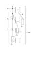
進路候補生成部61は、図2に示すように、自車両81の進路候補a1,a2を生成する。進路候補生成部61は、車両状態検出部2から入力される自車両81の位置、速度、向き等の情報から自車両81の未来の位置、速度、向き等の状態を予測する。そして、進路候補生成部61は、予測した自車両81の未来の状態における情報を進路候補a1,a2として生成し、分類部63に生成した進路候補a1,a2を出力する。The course
進路予測部62は、図3に示すように、走行環境に基づいて他車両82等、他の移動体の進路b1,b2,・・・,bnを予測する。進路予測部62は、環境状況取得部3から入力される他の移動体の位置、速度、向き等の情報から他移動体の未来の位置、速度、向き等の状態を予測する。そして、進路予測部62は、予測した他移動体の未来の状態における情報を進路b1,b2,・・・,bnとして予測し、分類部63に予測した進路b1,b2,・・・,bnを出力する。なお、一般的に、他車両82の進路b1,b2,・・・,bnは、自車両81の進路候補と比べて網羅的に予測される。As shown in FIG. 3, the
分類部63は、進路候補生成部61において生成された自車両81の進路候補a1,a2と、進路予測部62において予測された他移動体の予測進路b1,b2,・・・,bnとの干渉の状態を複数の干渉形態に分類する。具体的には、分類部63は、自車両81が他車両82の進路を干渉する干渉形態と、他車両82が自車両81の進路を干渉する干渉形態とに分類する。ここで、自車両81が他車両82の進路を干渉する状態とは、他車両82に対し自車両81が避けるべき状況において生じた干渉形態と定義する。The
進路評価部64は、分類部63において分類された干渉形態に基づいて自車両81の進路候補a1,a2を評価する。具体的には、進路評価部64は、分類部63によって自車両81が他車両82の進路を干渉する干渉形態と分類された進路候補を、自車両81が回避すべき進路として高く評価する。例えば、進路評価部64は、図2に示すように、自車両進路候補a1,a2と他車両予測進路b1,b2,・・・,b9との交差部について、自車両81が他車両82の進路を干渉しているのか、または、他車両82が自車両81の進路を干渉しているのかを判定する。次に、進路評価部64は、進路候補生成部61が生成したそれぞれの進路候補a1,a2について前述した交差部の干渉状態が、自車両81が他車両82の進路を干渉する交差部を1つでも有する場合、自車両81が回避すべき進路であるとして高く評価する。ここで、図2の○は、自車両81が他車両82の進路を干渉する交差部、図2の□は、他車両82が自車両81の進路を干渉する交差部を示している。The
なお、進路評価装置60を主に構成する進路候補生成部61と、進路予測部62と、分類部63と、進路評価部64とは、コンピュータにプログラムを導入することで構成してもよいし、個々のハードウェアによって構成してもよい。 The course
走行出力部9は、図1に示すように、車両制御ECU6に接続されており、車両制御ECU6の制御信号を受けて自車両81の運転走行、例えば、走行駆動、制動動作及び操舵操作を行う。走行出力部9としては、例えば、エンジンのスロットルバルブの開度を調整するアクチュエータを制御する走行駆動用ECU、ブレーキ油圧を調整するブレーキアクチュエータを制御する制動用ECU、操舵トルクを付与するステアリングアクチュエータを制御する操舵用ECU等が該当する。走行出力部9は、進路評価部64により自車両81が走行してもよいと高く評価された進路に従って自車両81の運転走行、例えば、走行駆動、制動動作及び操舵操作を行う。 As shown in FIG. 1, the travel output unit 9 is connected to the vehicle control ECU 6 and receives a control signal from the vehicle control ECU 6 to perform driving travel of the
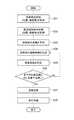
次に、進路評価装置60の動作について、図3を用いて説明する。図3は、進路評価装置60が実行する特徴的な処理の流れを示すフローチャートである。 Next, the operation of the
まず、車両状態検出部2は、自車両81の状態(位置、速度等)を取得する(S01)。そして、車両状態検出部2は、取得した情報を車両制御ECU6に出力する。 First, the vehicle
次に、環境状況取得部3は、自車両81周辺にある他物体の位置および状態を取得し(S02)、取得した情報を車両制御ECU6に出力する。以後、他物体の位置は、他物体の中心の値であるとし、他物体の状態は、位置、速度等によって特定されるものとする。 Next, the environmental
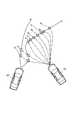
ところで、以下の工程で実行する軌跡を生成する演算を行う際、自車両81が予め設定された場所(目的地もしくは目的地に類する中間的な場所)に到達したか否かではなく、所定の期間で予測演算を打ち切る構成とすることは技術思想上重要である。一般に道路上では、事前に安全が保障されている場所はない。例えば、図4に示すように、3車線の道路Rdを走行する自車両O1が予め設定された場所Q1、Q2、Q3へ順次到達するとして予測を行うとき、その設定された場所に向けて自車両O1が同じ車線をほぼ直進していく場合を考慮に入れると、他車両O3が進路B3を取ることによって危険を回避するために進路B2をとって、他車両O2が自車両O1の走行している車線に進入してくるおそれがある。このように、従来の進路予測演算では、自車両O1が予め設定された場所へ走行するのが安全であるということまでは事前に保証されない。By the way, when performing calculation to generate a trajectory to be executed in the following steps, it is not a matter of whether or not the
本実施形態においては、自車両O1が到達すべき目的地等の場所を予め定めることなく、その都度最適な進路を判断しているため、図4と同じ状況下で、例えば、図5に示すような進路B1を自車両O1の進路として選択することができ、自車両O1が走行する際の危険を適確に回避して、安全性を確保することが可能となる。In the present embodiment, without the vehicle O1 is predetermined location of a destination such as to be reached, because it determines in each case the optimum route, under the same conditions as in FIG. 4, for example, in FIG. 5 the course B1 as shown can be selected as the path of the host vehicle O1, the risk when the vehicle O1 travels by avoiding the accurately, it is possible to ensure safety.
図3に戻り、進路予測部62は、環境状況取得部3において取得された他物体の位置及び状態に関する情報から他物体の未来の位置、状態を予測し、図3に示すような他物体の進路b1,b2,・・・,b9を予測する(S03)。なお、以下の説明では、他物体を他車両82として説明を行うが、車両以外の人、障害物等を対象としてもよい。Returning to FIG. 3, the
次に、進路候補生成部61は、車両状態検出部2において取得された自車両81周辺の物体の状態に関する情報から、自車両81の未来の位置、状態を予測し、図3に示すような進路候補a1,a2を生成する(S04)。具体的には、進路候補生成部61は、物体ごとに時間および空間から構成される時空間上の進路を生成する。なお、上記進路を生成するにあたっては、環境状況取得部3で取得した物体の総数(自車両81を含む)をKとし、一つの物体Ok(1≦k≦K、kは自然数)に対して進路を生成する演算をNk回行うものとする(この意味で、kおよびNkはともに自然数)。また、進路を生成する時間(軌跡生成時間)をT(>0)とする。なお、上記進路は、公知の方法によって算出することが可能であり、例えば、特開2007−230454公報に記載される方法によって算出することができる。Next, the course
次に、分類部63は、進路候補生成部61において生成された自車両81の進路候補a1,a2と、進路予測部62において予測された他移動体の予測進路b1,b2,・・・,b9との干渉状態を判定する(S05)。具体的には、図3に示すように、自車両81の進路候補a1,a2と、他車両82の予測進路b1,b2,・・・,b9との交差部について、自車両81が他車両82の進路を干渉しているのか、他車両82が自車両81の進路を干渉しているのかを判定する。なお、分類部63が上記干渉状態を分類するにあたっては、他車両への配慮を実現可能となる分類方法であればよく、例えば、干渉直前の進路のスムーズさ(曲率、加減速度等)の力学的な条件に基づく分類、交通ルールやマナーの遵守度、自動車保険の過失割合、裁判判例等の社会的規範に基づく分類、さらには各車両性能をも考慮した分類(自転車、小型車両には、より慎重を期する)等を行うことが可能である。Next, the
次に、分類部63は、ステップS05において判定された干渉状態に基づいて、進路候補を干渉形態別に分類する(S06)。ここでは、「自車両81が他車両進路を干渉する干渉形態」と「他車両82が自車両進路を干渉する干渉形態」とに分類される。分類部63は、図2示すように、進路候補a1,a2の中に自車両81が他車両進路を干渉する交差部(図3で示す○)を1つでも有する場合、その進路候補を、「自車両81が他車両進路を干渉する干渉形態」に分類する。図3において具体的に示すと、進路候補a1は、自車両81が他車両進路を干渉する交差部(図3で示す○)を有しているので、「自車両81が他車両進路を干渉する干渉形態」に分類され、進路候補a2は、他車両82が自車両進路を干渉する交差部(図3で示す□)のみで構成され、自車両81が他車両進路を干渉する交差部(図3で示す○)を有していないので、「他車両82が自車両進路を干渉する干渉形態」に分類される。ここで、進路候補の中に「他車両82が自車両進路を干渉する干渉形態」がない場合(S06:NO)、ステップS04に戻り、もう一度、進路候補を生成する(S04)。Next, the
次に、ステップS06において、進路候補a1,a2の中に「自車両81が他車両進路を干渉する干渉形態」がない場合(S06:YES)、進路評価部64は、その進路候補を自車両81が進むべき進路として高く評価する(S07)。そして、走行出力部9は、進路評価部64により自車両81が走行してもよいと高く評価された進路に従って自車両81の運転走行、例えば、走行駆動、制動動作及び操舵操作を行う(S08)。Next, in step S06, when there is no “interference form in which the
以上に説明したように本実施形態の走行支援装置1によれば、分類部63が、予め記憶された複数の干渉形態のパターンに基づいて干渉形態を分類し、進路評価部64が、その分類結果に基づいて進路候補を評価する。これにより、自車両81が他車両82の進路を干渉する干渉の形態を1つの干渉形態として分類することができ、また、避けるべき進路候補として高く評価することが可能となる。この結果、他車両82のドライバの操作を配慮した進路を走行することが可能となり、より安全な交通環境を実現することができる。 As described above, according to the driving
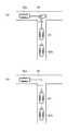
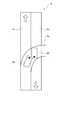
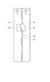
ここで、図6(a)、図6(b)を用いて、T字路に他車両82aと連なって本線道路90に進入する場合の走行制御について、本実施形態の走行支援装置1による効果を説明する。 Here, with reference to FIG. 6A and FIG. 6B, the effect of the traveling
従来の走行支援装置によれば、自車両の進路候補と他車両の予測進路との干渉形態を区別せずに、危険度が小さいと判定された進路に従って自車両81が走行制御される。このため、危険度が小さい場合には、例え、図6(a)に示すように、自車両81が本線道路90に進入する進路が他車両82aの進路を干渉する場合であっても、本線道路90に進入するように自車両81が走行制御される。そして、この場合の自車両81の動きは、他車両82aの進路を干渉するもの、すなわち、他車両82aに対し自車両81が避けるべき状況において生じる干渉である。このため、他車両82aのドライバに対して、急激な回避操作、制動操作を強いらせてしまうおそれがある。 According to the conventional travel support device, the travel of the
一方、本実施形態の走行支援装置1によれば、複数の進路候補において、前述したような本線道路90に進入する進路が最も危険度が低いと判定された場合であっても、分類部63が、その進路を「自車両81が他車両進路を干渉する干渉形態」に分類した場合、進路評価部64は、その進路を自車両81が回避すべき進路であると高く評価する。そして、進路評価部64は、分類部63によって「他車両82bが自車両進路を干渉する干渉形態」に分類された進路、すなわち、図6(b)に示すように、本線道路90に進入しない進路を自車両81が進むべき進路であると高く評価する。これにより、他車両82aに対し自車両81が避けるべき状況において生じる干渉を回避することができる。この結果、他車両82aのドライバの操作を配慮した進路を走行することが可能となり、より安全な交通環境を実現することができる。一方、他車両82aに対しては、自車両81に対し他車両82bが避けるべき状況において生じる干渉となり、自車両81と協力して干渉を避けることが可能となる。 On the other hand, according to the driving
以上、本発明の一実施形態について説明したが、本発明は上記実施形態に限られるものではなく、発明の趣旨を逸脱しない範囲で種々の変更が可能である。 As mentioned above, although one Embodiment of this invention was described, this invention is not limited to the said embodiment, A various change is possible in the range which does not deviate from the meaning of invention.
上記実施形態においては、図1に示すように、進路評価装置60は、進路候補生成部61と、進路予測部62と、分類部63と、進路評価部64とを含む例を挙げて説明したがこれに限るものではない。例えば、進路評価装置65は、図7に示すように、進路候補生成部61と、進路予測部62と、客観化部(客観化手段)66と、進路評価部(進路評価手段)67とを含んでいてもよい。なお、進路候補生成部61と進路予測部62とは、上記実施形態の進路評価装置60に含まれるものと同様であるので、ここではその説明を省略する。 In the above-described embodiment, as illustrated in FIG. 1, the
客観化部66は、図8に示すように、進路候補生成部61において生成された自車両81の進路候補a11,a12,a13と、進路予測部62において予測された他車両82の予測進路b11,b12,・・・,b20との干渉状態を客観的な数値で示す。具体的には、客観化部66は、他車両干渉率を算出する。ここで、「他車両干渉率」とは、進路候補a11,a12,a13と予測進路b11,b12,・・・,b20との全交差部における自車両81が他車両進路を干渉する交差部(図8で示す○)の割合をいう。図8において具体的に示すと、進路候補a11は、全交差部が10箇所、自車両81が他車両進路を干渉する交差部(図3で示す○)が8箇所有るので、他車両干渉率は80%となる。同様に、進路候補a11の他車両干渉率は50%、進路候補a13は0%となる。As shown in FIG. 8, the
進路評価部67は、客観化部66において示された数値に基づいて自車両81の進路を評価する。具体的には、進路評価部64は、客観化部66によって示された他車両干渉率の低い進路候補を、自車両81が回避すべき進路として高く評価する。例えば、進路評価部67は、他車両干渉率が20%以下の進路候補を自車両81が回避すべき進路であるとして高く評価する。なお、他車両干渉率の閾値は適宜設定することが可能である。 The
本実施形態の進路評価装置65によれば、予め定められた客観的な数値化のルールに従って干渉形態を数値化している。これにより、自車両81が他車両進路を干渉する干渉形態を特定することが可能となり、また、避けるべき進路候補として高く評価することが可能となる。この結果、他車両82のドライバの操作を配慮した進路を走行することが可能となり、より安全な交通環境を実現することができる。 According to the
また、走行支援装置1は、図7に示すように、表示部8をさらに備えていてもよい。表示部8は、進路評価部67において評価された進路候補の内容を表示する手段であり、例えば、モニタに表示したり、フロントガラスに投影したりする。具体的には、表示部8は、進路評価部67による進路候補の評価において、例えば、「他車両が自車両進路を干渉する干渉形態」と特定された進路と、「自車両が他車両進路を干渉する干渉形態」と特定された進路とを色分けして表示する。これにより、ドライバに対して自車両が進むべき進路、または、回避すべき進路を示すことが可能となる。 Moreover, the driving
また、走行支援装置1は、表示部8を有し、走行出力部9は有していなくてもよい。この場合であっても、ドライバに対して「他車両が自車両進路を干渉する干渉形態」である進路を認識させることができる。この場合であっても、ドライバは表示部8に示された進路に従って自車両を制御することが可能となる。この結果、自車両81を、他車両82のドライバの操作を配慮した進路を走行させることが可能となり、より安全な交通環境を実現することができる。 The driving
また、上記実施形態の走行支援装置1においては、分類部63が上記干渉状態を分類するにあたって、他車両への配慮を実現可能となる分類方法であればよく、例えば、干渉直前の進路のスムーズさ(曲率、加減速度等)の力学的な条件に基づく分類、交通ルールやマナーの遵守度、自動車保険の過失割合、裁判判例等の社会的規範に基づく分類、さらには各車両性能をも考慮した分類(自転車、小型車両には、より慎重を期する)等を行うことが可能であることを示した。以下に、分類部63が干渉状態を分類する方法を具体的に説明する。 Moreover, in the driving
例えば、図9に示すように、自車両81の向きと自車両81が位置する領域A1の進行方向との角度αに基づいて他車両82の進路を干渉する可能性を判定してもよい。例えば、自車両81の向きと自車両81が存在する領域の進行方向との角度αが所定角度以上(例えば、45度)の場合、自車両81は、他車両82の進路を干渉すると判定してもよい。 For example, as shown in FIG. 9, the possibility of interfering with the course of the
また、例えば、図10に示すように、自車両81の位置する領域A3と他車両82の位置する領域A2との優先順位に基づいて他車両82の進路を干渉する可能性を判定してもよい。例えば、自車両81の位置する領域A3が他車両82の位置する領域A2よりも低い場合、自車両81は、他車両82の進路を干渉すると判定してもよい。なお、自車両81の位置する領域A3と他車両82の位置する領域A2との優先順位の比較によれば、図11に示すような交差点において、自車両81が他車両82の進路を干渉する可能性を判定することも可能となる。また、自車両81が位置する領域に基づいた優先順位だけでなく、信号情報に基づいた優先順位を使用することも可能である。例えば、青信号であれば、その灯火が指し示された車両の優先順位は高く、赤信号であれば、その灯火が指し示された車両の優先順位は低い。 Further, for example, as shown in FIG. 10, the possibility of interfering with the course of the
また、例えば、図12に示すように、道路標示91,92に基づいて、自車両81が他車両82の進路を干渉する可能性を判定してもよい。ここで、道路標示91が白線、道路標示92が黄線である場合、領域A1を走行する自車両81が領域A2に車線変更することは交通ルールに違反する。そして、このような交通ルールを違反する走行は、自車両81が他車両82の進路を干渉すると判定してもよい。なお、交通ルールの違反の判定については、道路標示だけでなく、道路標識等も使用することができる。 Further, for example, as shown in FIG. 12, the possibility that the
また、例えば、図13(a)に示すように、自車両81と他車両82との干渉する部位を利用して、他車両82の進路を干渉する可能性を判定してもよい。なお、図13(a)に示す「A」は、自車両81が他車両82の進路を干渉、「B」は、他車両82が自車両81の進路を干渉することを示す。例えば、図13(b)に示すように、自車両81の進行方向前面と、他車両82の進行方向側面とが干渉する場合、図13(a)に示すように、自車両81が他車両82の進路を干渉すると判定してもよい。 Further, for example, as shown in FIG. 13A, the possibility of interfering with the course of the
1…走行支援装置、2…車両状態検出部、3…環境状況取得部、6…車両制御ECU、8…表示部、9…走行出力部、60,65…進路評価装置、61…進路候補生成部、62…進路予測部、63…分類部、64…進路評価部、66…客観化部、67…進路評価部、81…自車両、82,82a,82b…他車両、90…本線道路、91,92…道路標示、a1,a2…進路候補、a11,a12,a13…進路候補、b1,b2,・・・,b9…予測進路、b11,b12,・・・,b20…予測進路。DESCRIPTION OF
Claims (6)
Translated fromJapanese他移動体の進路を予測する進路予測手段と、
前記自車両の進路候補と前記他移動体の予測進路との干渉の形態を複数の干渉形態に分類する分類手段と、
前記分類手段において分類された前記干渉形態に基づいて前記自車両の進路候補を評価する進路評価手段と、
を備えることを特徴とする進路評価装置。A route candidate generating means for generating a route candidate of the host vehicle;
A course prediction means for predicting the course of another moving body;
Classification means for classifying the form of interference between the course candidate of the host vehicle and the predicted course of the other moving body into a plurality of interference forms;
A route evaluation unit that evaluates a route candidate of the host vehicle based on the interference mode classified by the classification unit;
A course evaluation apparatus comprising:
ことを特徴とする、請求項1に記載の進路評価装置。The classification means classifies the interference form based on the behavior of the host vehicle and the other moving body up to the interference.
The course evaluation apparatus according to claim 1, wherein:
前記進路評価手段は、前記他移動体が前記自車両の進路を干渉する形態と比べて、前記自車両が前記他移動体の進路を干渉する状態を、回避すべき進路として高く評価する、
ことを特徴とする、請求項1または2に記載の進路評価装置。The classification means classifies at least the form in which the host vehicle interferes with the path of the other moving body and the form in which the moving body interferes with the path of the own vehicle,
The course evaluation means highly evaluates the state in which the host vehicle interferes with the path of the other moving body as a path to be avoided, as compared with a mode in which the other moving body interferes with the path of the own vehicle.
The course evaluation apparatus according to claim 1, wherein the course evaluation apparatus is characterized.
他移動体の進路を予測する進路予測手段と、
前記自車両の進路候補と前記他移動体の予測進路との干渉の形態を客観的な数値で示す客観化手段と、
前記客観化手段において示された前記数値に基づいて前記自車両の進路候補を評価する進路評価手段と、
を備えることを特徴とする進路評価装置。A route candidate generating means for generating a route candidate of the host vehicle;
A course prediction means for predicting the course of another moving body;
Objective means for indicating the form of interference between the candidate course of the own vehicle and the predicted course of the other moving object by an objective numerical value;
A route evaluation unit that evaluates a route candidate of the host vehicle based on the numerical value shown in the objectification unit;
A course evaluation apparatus comprising:
ことを特徴とする、請求項4に記載の進路評価装置。The objectifying means shows the form of the interference as an objective numerical value based on the behavior of the host vehicle and the other moving body up to the interference.
The course evaluation apparatus according to claim 4, wherein:
前記進路評価手段は、前記干渉率が高いほど、回避すべき進路として高く評価する、
ことを特徴とする、請求項4または5に記載の進路評価装置。The objectifying means calculates an interference rate indicating a probability that the own vehicle interferes with a path of the other moving body,
The route evaluation means highly evaluates the route to be avoided as the interference rate is higher.
The course evaluation apparatus according to claim 4 or 5, characterized by the above-mentioned.
Priority Applications (7)
| Application Number | Priority Date | Filing Date | Title |
|---|---|---|---|
| JP2009141369AJP4957752B2 (en) | 2009-06-12 | 2009-06-12 | Course evaluation device |
| EP10731822.2AEP2441066B1 (en) | 2009-06-12 | 2010-06-08 | Route evaluation device |
| CN201080025534.XACN102803899B (en) | 2009-06-12 | 2010-06-08 | Route evaluation device |
| PCT/JP2010/059995WO2010143730A1 (en) | 2009-06-12 | 2010-06-08 | Route evaluation device |
| US13/321,159US9109906B2 (en) | 2009-06-12 | 2010-06-08 | Route evaluation device |
| US14/792,187US9731718B2 (en) | 2009-06-12 | 2015-07-06 | Route evaluation device |
| US15/644,190US10239523B2 (en) | 2009-06-12 | 2017-07-07 | Route evaluation device |
Applications Claiming Priority (1)
| Application Number | Priority Date | Filing Date | Title |
|---|---|---|---|
| JP2009141369AJP4957752B2 (en) | 2009-06-12 | 2009-06-12 | Course evaluation device |
Publications (2)
| Publication Number | Publication Date |
|---|---|
| JP2010287109Atrue JP2010287109A (en) | 2010-12-24 |
| JP4957752B2 JP4957752B2 (en) | 2012-06-20 |
Family
ID=42668069
Family Applications (1)
| Application Number | Title | Priority Date | Filing Date |
|---|---|---|---|
| JP2009141369AActiveJP4957752B2 (en) | 2009-06-12 | 2009-06-12 | Course evaluation device |
Country Status (5)
| Country | Link |
|---|---|
| US (3) | US9109906B2 (en) |
| EP (1) | EP2441066B1 (en) |
| JP (1) | JP4957752B2 (en) |
| CN (1) | CN102803899B (en) |
| WO (1) | WO2010143730A1 (en) |
Cited By (10)
| Publication number | Priority date | Publication date | Assignee | Title |
|---|---|---|---|---|
| JP2012513651A (en)* | 2008-12-23 | 2012-06-14 | コンテイネンタル・セイフテイ・エンジニヤリング・インターナシヨナル・ゲゼルシヤフト・ミツト・ベシユレンクテル・ハフツング | Method of determining collision probability between vehicle and living thing |
| JP2012179929A (en)* | 2011-02-28 | 2012-09-20 | Toyota Motor Corp | Course evaluation device |
| JP2012256241A (en)* | 2011-06-09 | 2012-12-27 | Toyota Motor Corp | Course evaluation device and course evaluation method |
| JP2012256242A (en)* | 2011-06-09 | 2012-12-27 | Toyota Motor Corp | Other vehicle recognition device and course evaluation device |
| CN103946068A (en)* | 2011-11-18 | 2014-07-23 | 丰田自动车株式会社 | Traveling environment prediction device, vehicle control device, and methods therefor |
| JP2018500661A (en)* | 2014-12-09 | 2018-01-11 | トヨタ モーター エンジニアリング アンド マニュファクチャリング ノース アメリカ,インコーポレイティド | Priority detection and response at autonomous vehicle intersections |
| KR20210003751A (en)* | 2018-04-24 | 2021-01-12 | 로베르트 보쉬 게엠베하 | Method and apparatus for cooperative coordination between future driving maneuvers of one vehicle and driving maneuvers of at least one other vehicle |
| JP2021522102A (en)* | 2018-04-24 | 2021-08-30 | ロバート ボッシュ ゲゼルシャフト ミット ベシュレンクテル ハフツングRobert Bosch GmbH | Methods and devices for coordinated coordination between future driving operations of the vehicle and the operation of at least one companion vehicle companion. |
| JP2022058579A (en)* | 2021-04-16 | 2022-04-12 | 阿波▲羅▼智▲聯▼(北京)科技有限公司 | Vehicle driving control method and equipment |
| JP2023527373A (en)* | 2020-05-27 | 2023-06-28 | ズークス インコーポレイテッド | Vehicle Collision Avoidance Based on Perturbed Object Trajectory |
Families Citing this family (23)
| Publication number | Priority date | Publication date | Assignee | Title |
|---|---|---|---|---|
| EP2508956B1 (en)* | 2011-04-06 | 2013-10-30 | Kollmorgen Särö AB | A collision avoiding method and system |
| US8706413B2 (en) | 2011-10-17 | 2014-04-22 | Qualcomm Incorporated | Determining a likelihood of a directional transition at a junction in an encoded routability graph description |
| US20130103305A1 (en)* | 2011-10-19 | 2013-04-25 | Robert Bosch Gmbh | System for the navigation of oversized vehicles |
| FR2988507B1 (en)* | 2012-03-23 | 2014-04-25 | Inst Francais Des Sciences Et Technologies Des Transports De Lamenagement Et Des Reseaux | ASSISTANCE SYSTEM FOR A ROAD VEHICLE |
| DE102013201891A1 (en)* | 2013-02-06 | 2014-08-07 | Robert Bosch Gmbh | Method for preventing a lateral collision in a vehicle |
| US9146120B2 (en)* | 2013-05-07 | 2015-09-29 | Telenav Inc. | Navigation system with route classification mechanism and method of operation thereof |
| JP2015075957A (en)* | 2013-10-09 | 2015-04-20 | 本田技研工業株式会社 | Driving support device, vehicle, and control program |
| KR102051142B1 (en)* | 2014-06-13 | 2019-12-02 | 현대모비스 주식회사 | System for managing dangerous driving index for vehicle and method therof |
| JP6225927B2 (en)* | 2015-02-02 | 2017-11-08 | トヨタ自動車株式会社 | Vehicle state prediction system |
| KR101714273B1 (en)* | 2015-12-11 | 2017-03-08 | 현대자동차주식회사 | Method and apparatus for controlling path of autonomous driving system |
| JP6294905B2 (en)* | 2016-03-31 | 2018-03-14 | 株式会社Subaru | Display device |
| US20200118433A1 (en)* | 2017-03-31 | 2020-04-16 | Aisin Aw Co., Ltd. | Drive assistance system |
| JP6558393B2 (en) | 2017-04-06 | 2019-08-14 | トヨタ自動車株式会社 | Course setting device and course setting method |
| DE102017209287B4 (en)* | 2017-06-01 | 2022-10-13 | Robert Bosch Gmbh | Method and control device for controlling an automated means of transport in a pedestrian zone |
| KR101989102B1 (en)* | 2017-09-13 | 2019-06-13 | 엘지전자 주식회사 | Driving assistance Apparatus for Vehicle and Control method thereof |
| CN108609016A (en)* | 2018-03-12 | 2018-10-02 | 上海伊控动力系统有限公司 | A kind of Vehicular intelligent speed limiting system and method based on vehicle net |
| DE102018133157A1 (en) | 2018-12-20 | 2020-06-25 | Daimler Ag | Method for the automated control of a vehicle at a pedestrian crossing, control device |
| WO2020127689A1 (en) | 2018-12-20 | 2020-06-25 | Robert Bosch Gmbh | Method for the automated control of a vehicle at a pedestrian crosswalk, control unit |
| US10755565B2 (en)* | 2019-01-18 | 2020-08-25 | Ford Global Technologies, Llc | Prioritized vehicle messaging |
| JP7400754B2 (en) | 2021-02-24 | 2023-12-19 | トヨタ自動車株式会社 | Remote support system and remote support method |
| JP7388376B2 (en)* | 2021-02-24 | 2023-11-29 | トヨタ自動車株式会社 | Remote support system, remote support method, and remote support program |
| CN120642353A (en)* | 2023-02-03 | 2025-09-12 | Lg电子株式会社 | Method for transmitting message by terminal in wireless communication system and apparatus therefor |
| DE102023106657B3 (en)* | 2023-03-16 | 2024-05-08 | Bayerische Motoren Werke Aktiengesellschaft | Driving assistance method for vehicles and system for performing cooperative driving maneuvers by several vehicles |
Citations (3)
| Publication number | Priority date | Publication date | Assignee | Title |
|---|---|---|---|---|
| JP2004326149A (en)* | 2003-04-21 | 2004-11-18 | Aichi Prefecture | Vehicle collision warning device |
| JP2009026321A (en)* | 2008-08-25 | 2009-02-05 | Toyota Motor Corp | Interference evaluation method, apparatus, and program |
| JP2009064088A (en)* | 2007-09-04 | 2009-03-26 | Toyota Motor Corp | Mobile body course acquisition method and mobile body course acquisition apparatus |
Family Cites Families (49)
| Publication number | Priority date | Publication date | Assignee | Title |
|---|---|---|---|---|
| DE4317960A1 (en)* | 1993-05-28 | 1995-01-12 | Bayerische Motoren Werke Ag | Method for avoiding a collision of a motor vehicle |
| US8965677B2 (en)* | 1998-10-22 | 2015-02-24 | Intelligent Technologies International, Inc. | Intra-vehicle information conveyance system and method |
| US6445308B1 (en)* | 1999-01-12 | 2002-09-03 | Toyota Jidosha Kabushiki Kaisha | Positional data utilizing inter-vehicle communication method and traveling control apparatus |
| DE10036276A1 (en)* | 2000-07-26 | 2002-02-07 | Daimler Chrysler Ag | Automatic braking and steering system for a vehicle |
| US7752061B2 (en)* | 2000-10-02 | 2010-07-06 | Computer Sciences Corporation | Computerized method and system of displaying an accident type |
| US6792351B2 (en)* | 2001-06-26 | 2004-09-14 | Medius, Inc. | Method and apparatus for multi-vehicle communication |
| DE10257842A1 (en) | 2002-05-07 | 2003-11-27 | Bosch Gmbh Robert | Determining risk of accident between first vehicle and at least one second object involves determining collision probability and hazard probability from movements of first object and second object |
| US6650983B1 (en)* | 2002-07-23 | 2003-11-18 | Ford Global Technologies, Llc | Method for classifying an impact in a pre-crash sensing system in a vehicle having a countermeasure system |
| JP3689076B2 (en)* | 2002-09-05 | 2005-08-31 | 株式会社東芝 | Automotive electronics |
| JP3870911B2 (en)* | 2003-02-10 | 2007-01-24 | 日産自動車株式会社 | Lane departure prevention device |
| JP4578795B2 (en)* | 2003-03-26 | 2010-11-10 | 富士通テン株式会社 | Vehicle control device, vehicle control method, and vehicle control program |
| US7349767B2 (en)* | 2003-12-16 | 2008-03-25 | Nissan Motor Co., Ltd. | Method and system for intention estimation and operation assistance |
| US7447592B2 (en)* | 2004-10-18 | 2008-11-04 | Ford Global Technologies Llc | Path estimation and confidence level determination system for a vehicle |
| JP4421450B2 (en)* | 2004-11-22 | 2010-02-24 | 本田技研工業株式会社 | Vehicle departure determination device |
| DE112005003266T5 (en) | 2004-12-28 | 2008-09-04 | Kabushiki Kaisha Toyota Chuo Kenkyusho | Vehicle motion control device |
| JP2006205860A (en)* | 2005-01-27 | 2006-08-10 | Advics:Kk | Vehicle traveling support device |
| JP4062310B2 (en)* | 2005-02-07 | 2008-03-19 | 日産自動車株式会社 | Driving intention estimation device, vehicle driving assistance device, and vehicle equipped with vehicle driving assistance device |
| US7444241B2 (en)* | 2005-12-09 | 2008-10-28 | Gm Global Technology Operations, Inc. | Method for detecting or predicting vehicle cut-ins |
| JP4997778B2 (en) | 2006-02-13 | 2012-08-08 | トヨタ自動車株式会社 | Crew protection device |
| JP4353192B2 (en) | 2006-03-02 | 2009-10-28 | トヨタ自動車株式会社 | Course setting method, apparatus, program, and automatic driving system |
| WO2007102367A1 (en)* | 2006-02-28 | 2007-09-13 | Toyota Jidosha Kabushiki Kaisha | Object course prediction method, device, program, and automatic driving system |
| US20070225914A1 (en)* | 2006-03-21 | 2007-09-27 | Hiroshi Kawazoe | Lane departure avoidance control |
| JP5130638B2 (en)* | 2006-03-22 | 2013-01-30 | 日産自動車株式会社 | Avoidance operation calculation device, avoidance control device, vehicle including each device, avoidance operation calculation method, and avoidance control method |
| JP2007257519A (en)* | 2006-03-24 | 2007-10-04 | Mazda Motor Corp | Vehicular travel support device |
| JP4638370B2 (en)* | 2006-03-29 | 2011-02-23 | 富士重工業株式会社 | Lane departure prevention device |
| EP1849669B1 (en)* | 2006-04-28 | 2011-10-05 | Nissan Motor Co., Ltd. | Lane departure prevention apparatus and method for a motor vehicle |
| JP4650362B2 (en)* | 2006-07-18 | 2011-03-16 | 日産自動車株式会社 | Lane departure prevention device |
| JP4062353B1 (en)* | 2006-11-10 | 2008-03-19 | トヨタ自動車株式会社 | Obstacle course prediction method, apparatus, and program |
| US20080167820A1 (en)* | 2007-01-04 | 2008-07-10 | Kentaro Oguchi | System for predicting driver behavior |
| JP4400634B2 (en)* | 2007-02-28 | 2010-01-20 | トヨタ自動車株式会社 | Collision prediction device |
| US20080228400A1 (en)* | 2007-03-15 | 2008-09-18 | Wheeler Jeffrey D | Highway safety system and method |
| JP5244787B2 (en)* | 2007-03-29 | 2013-07-24 | トヨタ自動車株式会社 | Collision possibility acquisition device and collision possibility acquisition method |
| JP5309582B2 (en)* | 2007-05-11 | 2013-10-09 | 日産自動車株式会社 | Vehicle traveling control method and traveling control device |
| JP4623057B2 (en)* | 2007-06-05 | 2011-02-02 | トヨタ自動車株式会社 | Moving area acquisition device for own vehicle |
| JP4207088B2 (en) | 2007-06-20 | 2009-01-14 | トヨタ自動車株式会社 | Vehicle travel estimation device |
| JP4450023B2 (en)* | 2007-07-12 | 2010-04-14 | トヨタ自動車株式会社 | Own vehicle risk acquisition device |
| US7904223B2 (en)* | 2007-10-12 | 2011-03-08 | Ford Global Technologies, Llc | Post impact safety system with vehicle contact information |
| EP2062796B1 (en)* | 2007-11-20 | 2010-08-04 | Nissan Motor Co., Ltd. | Lane deviation prevention device and method |
| DE102007058538A1 (en) | 2007-12-06 | 2009-06-10 | Robert Bosch Gmbh | Method for controlling a hazardous situation in traffic |
| JP5359085B2 (en)* | 2008-03-04 | 2013-12-04 | 日産自動車株式会社 | Lane maintenance support device and lane maintenance support method |
| JP5359516B2 (en)* | 2008-07-29 | 2013-12-04 | 日産自動車株式会社 | Vehicle driving support device and vehicle driving support method |
| JP5200732B2 (en)* | 2008-07-29 | 2013-06-05 | 日産自動車株式会社 | Travel control device and travel control method |
| FR2935825B1 (en)* | 2008-09-09 | 2010-09-24 | Thales Sa | VISUALIZATION DEVICE FOR AIRCRAFT COMPRISING DISPLAY MEANS FOR INTRUS TRAJECTORIES HAVING COLLISION RISK IN THE ENTIRE AIRCRAFT SURROUNDING AREA |
| JP5174609B2 (en)* | 2008-10-10 | 2013-04-03 | 日立オートモティブシステムズ株式会社 | Driving support device |
| US7991552B2 (en)* | 2008-11-06 | 2011-08-02 | Ford Global Technologies, Llc | System and method for determining a side-impact collision status of a nearby vehicle |
| GB0901906D0 (en)* | 2009-02-05 | 2009-03-11 | Trw Ltd | Collision warning apparatus |
| JP2010188981A (en)* | 2009-02-20 | 2010-09-02 | Fuji Heavy Ind Ltd | Driving support device of vehicle |
| US20120277957A1 (en)* | 2010-04-15 | 2012-11-01 | Satoru Inoue | Driving assist device |
| US9177477B2 (en)* | 2010-07-19 | 2015-11-03 | Honda Motor Co., Ltd. | Collision warning system using driver intention estimator |
- 2009
- 2009-06-12JPJP2009141369Apatent/JP4957752B2/enactiveActive
- 2010
- 2010-06-08USUS13/321,159patent/US9109906B2/enactiveActive
- 2010-06-08CNCN201080025534.XApatent/CN102803899B/enactiveActive
- 2010-06-08EPEP10731822.2Apatent/EP2441066B1/enactiveActive
- 2010-06-08WOPCT/JP2010/059995patent/WO2010143730A1/enactiveApplication Filing
- 2015
- 2015-07-06USUS14/792,187patent/US9731718B2/enactiveActive
- 2017
- 2017-07-07USUS15/644,190patent/US10239523B2/enactiveActive
Patent Citations (3)
| Publication number | Priority date | Publication date | Assignee | Title |
|---|---|---|---|---|
| JP2004326149A (en)* | 2003-04-21 | 2004-11-18 | Aichi Prefecture | Vehicle collision warning device |
| JP2009064088A (en)* | 2007-09-04 | 2009-03-26 | Toyota Motor Corp | Mobile body course acquisition method and mobile body course acquisition apparatus |
| JP2009026321A (en)* | 2008-08-25 | 2009-02-05 | Toyota Motor Corp | Interference evaluation method, apparatus, and program |
Cited By (17)
| Publication number | Priority date | Publication date | Assignee | Title |
|---|---|---|---|---|
| JP2012513651A (en)* | 2008-12-23 | 2012-06-14 | コンテイネンタル・セイフテイ・エンジニヤリング・インターナシヨナル・ゲゼルシヤフト・ミツト・ベシユレンクテル・ハフツング | Method of determining collision probability between vehicle and living thing |
| JP2012179929A (en)* | 2011-02-28 | 2012-09-20 | Toyota Motor Corp | Course evaluation device |
| JP2012256241A (en)* | 2011-06-09 | 2012-12-27 | Toyota Motor Corp | Course evaluation device and course evaluation method |
| JP2012256242A (en)* | 2011-06-09 | 2012-12-27 | Toyota Motor Corp | Other vehicle recognition device and course evaluation device |
| CN103946068A (en)* | 2011-11-18 | 2014-07-23 | 丰田自动车株式会社 | Traveling environment prediction device, vehicle control device, and methods therefor |
| CN103946068B (en)* | 2011-11-18 | 2016-11-23 | 丰田自动车株式会社 | Running environment prediction means and controller of vehicle and method thereof |
| JP2018500661A (en)* | 2014-12-09 | 2018-01-11 | トヨタ モーター エンジニアリング アンド マニュファクチャリング ノース アメリカ,インコーポレイティド | Priority detection and response at autonomous vehicle intersections |
| JP2021522102A (en)* | 2018-04-24 | 2021-08-30 | ロバート ボッシュ ゲゼルシャフト ミット ベシュレンクテル ハフツングRobert Bosch GmbH | Methods and devices for coordinated coordination between future driving operations of the vehicle and the operation of at least one companion vehicle companion. |
| KR20210003751A (en)* | 2018-04-24 | 2021-01-12 | 로베르트 보쉬 게엠베하 | Method and apparatus for cooperative coordination between future driving maneuvers of one vehicle and driving maneuvers of at least one other vehicle |
| US11377118B2 (en) | 2018-04-24 | 2022-07-05 | Robert Bosch Gmbh | Method and apparatus for cooperatively coordinating future driving maneuvers of a vehicle with foreign maneuvers of at least one foreign vehicle |
| JP7177973B2 (en) | 2018-04-24 | 2022-11-25 | ロバート ボッシュ ゲゼルシャフト ミット ベシュレンクテル ハフツング | Method and apparatus and computer program product and machine-readable storage medium for cooperative coordination of future driving maneuvers of a vehicle and the maneuvers of at least one fellow vehicle companion |
| US11535247B2 (en) | 2018-04-24 | 2022-12-27 | Robert Bosch Gmbh | Method and device for a cooperative coordination between future driving maneuvers of one vehicle and the maneuvers of at least one other vehicle |
| KR102524202B1 (en) | 2018-04-24 | 2023-04-25 | 로베르트 보쉬 게엠베하 | Method and apparatus for cooperative coordination between future driving maneuvers of one vehicle and driving maneuvers of at least one other vehicle |
| JP2023527373A (en)* | 2020-05-27 | 2023-06-28 | ズークス インコーポレイテッド | Vehicle Collision Avoidance Based on Perturbed Object Trajectory |
| JP2022058579A (en)* | 2021-04-16 | 2022-04-12 | 阿波▲羅▼智▲聯▼(北京)科技有限公司 | Vehicle driving control method and equipment |
| JP7322201B2 (en) | 2021-04-16 | 2023-08-07 | 阿波▲羅▼智▲聯▼(北京)科技有限公司 | VEHICLE RUNNING CONTROL METHOD AND DEVICE |
| US12024166B2 (en) | 2021-04-16 | 2024-07-02 | Apollo Intelligent Connectivity (Beijing) Technology Co., Ltd. | Vehicle driving control method and apparatus |
Also Published As
| Publication number | Publication date |
|---|---|
| US9109906B2 (en) | 2015-08-18 |
| US9731718B2 (en) | 2017-08-15 |
| EP2441066A1 (en) | 2012-04-18 |
| US20150307092A1 (en) | 2015-10-29 |
| CN102803899B (en) | 2016-03-23 |
| CN102803899A (en) | 2012-11-28 |
| JP4957752B2 (en) | 2012-06-20 |
| US20170334442A1 (en) | 2017-11-23 |
| WO2010143730A1 (en) | 2010-12-16 |
| US20120072104A1 (en) | 2012-03-22 |
| EP2441066B1 (en) | 2016-11-30 |
| US10239523B2 (en) | 2019-03-26 |
Similar Documents
| Publication | Publication Date | Title |
|---|---|---|
| JP4957752B2 (en) | Course evaluation device | |
| CN110488802B (en) | Decision-making method for dynamic behaviors of automatic driving vehicle in internet environment | |
| CN102449672B (en) | Vehicular peripheral surveillance device | |
| US8676487B2 (en) | Apparatus for predicting the movement of a mobile body | |
| JP4254844B2 (en) | Travel control plan evaluation device | |
| CN104169136B (en) | Drive assistance device | |
| US20220314968A1 (en) | Electronic control device | |
| JP6428928B2 (en) | Occlusion controller | |
| JP6468261B2 (en) | Automated driving system | |
| JP7145815B2 (en) | electronic controller | |
| US11731661B2 (en) | Systems and methods for imminent collision avoidance | |
| JP2021111366A (en) | How to create stochastic free spatial maps with static and dynamic objects | |
| JP2009101733A (en) | Vehicle travel control device | |
| US20110054793A1 (en) | Environment prediction device | |
| US11661061B2 (en) | Method and device for assisting a driver in a vehicle | |
| JP2005056372A5 (en) | ||
| EP3715791A1 (en) | Vehicle driving support system, method, computer-program product, and vehicle | |
| CN112590778A (en) | Vehicle control method and device, controller and intelligent automobile | |
| CN114132311A (en) | Method and module for screening dangerous targets for automatic emergency braking of vehicle | |
| CN118053321A (en) | Vehicle collision threat assessment | |
| JP5505391B2 (en) | Environmental prediction device | |
| Silberling et al. | Development and application of a collision avoidance capability metric | |
| JP6330868B2 (en) | Vehicle control device | |
| JP2021033536A (en) | Vehicle control device and vehicle control method | |
| JP5636854B2 (en) | Course evaluation device |
Legal Events
| Date | Code | Title | Description |
|---|---|---|---|
| A131 | Notification of reasons for refusal | Free format text:JAPANESE INTERMEDIATE CODE: A131 Effective date:20110927 | |
| A521 | Request for written amendment filed | Free format text:JAPANESE INTERMEDIATE CODE: A523 Effective date:20111122 | |
| TRDD | Decision of grant or rejection written | ||
| A01 | Written decision to grant a patent or to grant a registration (utility model) | Free format text:JAPANESE INTERMEDIATE CODE: A01 Effective date:20120221 | |
| A01 | Written decision to grant a patent or to grant a registration (utility model) | Free format text:JAPANESE INTERMEDIATE CODE: A01 | |
| A61 | First payment of annual fees (during grant procedure) | Free format text:JAPANESE INTERMEDIATE CODE: A61 Effective date:20120305 | |
| FPAY | Renewal fee payment (event date is renewal date of database) | Free format text:PAYMENT UNTIL: 20150330 Year of fee payment:3 | |
| R151 | Written notification of patent or utility model registration | Ref document number:4957752 Country of ref document:JP Free format text:JAPANESE INTERMEDIATE CODE: R151 |