JP2010284982A - Intelligent type electronic air pressure automatically adjusting suspension system - Google Patents
Intelligent type electronic air pressure automatically adjusting suspension systemDownload PDFInfo
- Publication number
- JP2010284982A JP2010284982AJP2009137947AJP2009137947AJP2010284982AJP 2010284982 AJP2010284982 AJP 2010284982AJP 2009137947 AJP2009137947 AJP 2009137947AJP 2009137947 AJP2009137947 AJP 2009137947AJP 2010284982 AJP2010284982 AJP 2010284982A
- Authority
- JP
- Japan
- Prior art keywords
- solenoid valve
- sensor
- air
- control end
- air shock
- Prior art date
- Legal status (The legal status is an assumption and is not a legal conclusion. Google has not performed a legal analysis and makes no representation as to the accuracy of the status listed.)
- Pending
Links
- 239000000725suspensionSubstances0.000titleclaimsabstractdescription31
- 230000035939shockEffects0.000claimsabstractdescription80
- 239000006096absorbing agentSubstances0.000claimsabstractdescription78
- 230000005540biological transmissionEffects0.000claimsabstractdescription36
- 230000007246mechanismEffects0.000claimsabstractdescription17
- 238000012544monitoring processMethods0.000claimsdescription32
- 238000005516engineering processMethods0.000claimsdescription7
- 238000005259measurementMethods0.000claimsdescription5
- 230000008054signal transmissionEffects0.000claimsdescription5
- 238000000034methodMethods0.000description18
- 238000013016dampingMethods0.000description13
- 238000010586diagramMethods0.000description11
- 230000008859changeEffects0.000description10
- 230000006870functionEffects0.000description10
- 230000001133accelerationEffects0.000description8
- 230000008569processEffects0.000description6
- 230000033001locomotionEffects0.000description5
- XUIMIQQOPSSXEZ-UHFFFAOYSA-NSiliconChemical compound[Si]XUIMIQQOPSSXEZ-UHFFFAOYSA-N0.000description3
- 230000009471actionEffects0.000description3
- 230000004044responseEffects0.000description3
- 229910052710siliconInorganic materials0.000description3
- 239000010703siliconSubstances0.000description3
- 239000003990capacitorSubstances0.000description2
- 238000013461designMethods0.000description2
- 230000000694effectsEffects0.000description2
- 239000004973liquid crystal related substanceSubstances0.000description2
- 238000005459micromachiningMethods0.000description2
- 230000005405multipoleEffects0.000description2
- 239000003381stabilizerSubstances0.000description2
- 238000012360testing methodMethods0.000description2
- 229910000831SteelInorganic materials0.000description1
- 238000004891communicationMethods0.000description1
- 238000010276constructionMethods0.000description1
- 238000012937correctionMethods0.000description1
- 230000007812deficiencyEffects0.000description1
- 230000002349favourable effectEffects0.000description1
- 238000001914filtrationMethods0.000description1
- 239000011521glassSubstances0.000description1
- 230000005484gravityEffects0.000description1
- 230000005283ground stateEffects0.000description1
- 230000006872improvementEffects0.000description1
- 238000002347injectionMethods0.000description1
- 239000007924injectionSubstances0.000description1
- 238000009434installationMethods0.000description1
- 239000000463materialSubstances0.000description1
- 239000002184metalSubstances0.000description1
- 230000003287optical effectEffects0.000description1
- 238000012545processingMethods0.000description1
- 239000011347resinSubstances0.000description1
- 229920005989resinPolymers0.000description1
- -1speed sensorSubstances0.000description1
- 239000010959steelSubstances0.000description1
- 239000000758substrateSubstances0.000description1
- 238000009423ventilationMethods0.000description1
Images


Landscapes
- Vehicle Body Suspensions (AREA)
Abstract
Description
Translated fromJapanese本発明は、インテリジェント型電子気圧自動調整式サスペンションシステムに関し、詳しくはユーザーの需要に応じて自動車のエアショックアブソーバーの設定を即時に自動調整することを可能にするシステムに関するものである。 The present invention relates to an intelligent electronic air pressure automatic adjustment suspension system, and more particularly to a system that enables an automatic adjustment of an air shock absorber setting of an automobile in response to a user demand.
サスペンションシステム(Suspension System)の作用は、自動車が走行する最中に振動および衝撃を緩衝し、激しい振動および衝撃を避けることが可能である。簡単に言えば、サスペンションシステムは車体および車輪との間の構造であり、車体を支持するほかに乗客に良好な乗り心地を提供する。従来のサスペンションシステムは、主に受動式のサスペンション(Passive Suspension)または機械式サスペンション(Mechanical Suspension)であり、スプリング(Spring)、ショックアブソーバー(Shock Absorber)、リンク(Link)、制御アームおよびスタビライザーバー(Stabilizer Bar)などから構成される。その機能は、車両全体、乗客および貨物などを支持し、かつ平坦でない路面を走行する際に生じる車輪の激しい上下振動を吸収し、車両内の機構が振動を受けて損傷してしまうという現象を減少させることが可能なだけでなく、車体の振動エネルギーを最小に減少させ、乗客に良好な乗り心地をもたらし、走行中の安全性を改善することが可能である。 The action of the suspension system can dampen vibrations and shocks while the automobile is running, and avoid severe vibrations and shocks. Simply put, the suspension system is the structure between the car body and the wheels, and provides a good ride for passengers in addition to supporting the car body. The conventional suspension system is mainly a passive suspension or a mechanical suspension, and includes a spring, a shock absorber, a link, a control arm, and a stabilizer bar. (Stabilizer Bar). Its function is to support the entire vehicle, passengers, cargo, etc., and absorb the intense vertical vibrations of the wheels that occur when traveling on uneven road surfaces, and the mechanism in the vehicle will be damaged by vibration. In addition to being able to reduce, it is possible to reduce the vibration energy of the car body to a minimum, bring a good ride to the passengers and improve safety during travel.
自動車に使用されているサスペンションシステムの大半は、緩衝ユニットとしてコイル状のスプリングを採用する。緩衝ユニットとしてのコイル状のスプリングは相当古くから自動車工業に採用されているため、振動防止の基本的な効果を達成することが可能であるといえる。 Most suspension systems used in automobiles employ a coiled spring as a buffer unit. Since the coiled spring as the buffer unit has been adopted in the automobile industry for a long time, it can be said that the fundamental effect of preventing vibration can be achieved.
コイル状のスプリングの全体構造を分析してみると、コイル状のスプリングは提供可能な弾性支持範囲が出荷の際にすでに設定されているため、使用中に任意に調整することはできない。台湾特許第M251958号により掲示される調整可能なダンビング装置は、ダンビング値C/T(そのうち、Cは圧力側、Tは引っ張る側である)が配置されるため、自動車または路面の状況に応じ、ダンビング値の変化を調整することが可能である。 Analyzing the overall structure of the coiled spring, the coiled spring cannot be arbitrarily adjusted during use because the elastic support range that can be provided is already set at the time of shipment. The adjustable dampening device posted by Taiwan Patent No. M251958 has a damping value C / T (where C is the pressure side and T is the pulling side), so depending on the situation of the car or road surface, It is possible to adjust the change of the damping value.
ダンビング値を調整可能なコイル状のスプリングショックアブソーバーは、従来のスプリングおよびダンビング装置から構成される。スプリングは一定のスプリング常数K値を有し、ダンビング装置はダンビング値C/Tを有する。そのうち、Cは圧力側であり、Tは引っ張る側である。しかしながら、従来のダンビング値を調整可能なコイル状のスプリングショックアブソーバーは、ダンビング値C/Tが一定のスプリング常数Kに対応するため、効果は芳しくない。 A coiled spring shock absorber capable of adjusting a damping value is composed of a conventional spring and a damping device. The spring has a constant spring constant K value, and the damping device has a damping value C / T. Of these, C is the pressure side and T is the pulling side. However, the conventional coiled spring shock absorber capable of adjusting the damping value is not effective because the damping value C / T corresponds to a constant spring constant K.
上述したダンビング値を調整可能なコイル状のスプリングショックアブソーバーは、従来のショックアブソーバーの欠点を解決可能である。かつ自動車が走行する際、ダンビング値を調整することによって自動車の快適性および操作能力の変化を小幅に調整することはできるが、車両の動的水平および高度の変化に対応して調整することはできない。 The coiled spring shock absorber capable of adjusting the damping value described above can solve the drawbacks of the conventional shock absorber. And when the car is running, it is possible to adjust the changes in the comfort and operating ability of the car to a small extent by adjusting the damping value. Can not.
言い換えれば、自動車が上ったり下ったりする時、自動車が荷物を載せる時、自動車が急加速したり急減速したりする時および自動車がでこぼこの路面を走行する時、タイヤおよび車体は沈んだり浮き上がったりするという現象が生じる。このとき、上述したダンビング値を調整可能なコイル状のスプリングショックアブソーバーの設定が路面状況に即時対応できなければ、車内の運転手または乗客によくない乗り心地をもたらすだけでなく、長期間にわたって持続すれば自動車の車台を損壊させてしまう。また積載量の比較的大きいトラックの場合、積載重量のバランスが取れなければ、車台を傾斜させてしまうだけでなく、ショックアブソーバーが長期間にわたって底部に接触して圧迫を与えれば、ショックアブソーバーの使用寿命を短縮してしまう。 In other words, when the car goes up and down, when the car loads, when the car suddenly accelerates and decelerates, and when the car runs on rough roads, the tires and the body sink and rise. Phenomenon occurs. At this time, if the setting of the coiled spring shock absorber capable of adjusting the damping value described above cannot respond immediately to the road surface condition, it will not only give a bad ride comfort to the driver or passenger in the car, but will also last for a long period of time. Doing so will damage the car chassis. For trucks with relatively large loading capacity, if the load weight is not balanced, the chassis will not only be tilted, but if the shock absorber touches the bottom for a long period of time and pressure is applied, the use of the shock absorber It will shorten the service life.
緩衝ユニットとしてのエアスプリング(air spring)から構成されるショックアブソーバー、例えば米国特許第7,420,462号により掲示される『AIR SPRING DISTANCE INDICATING SYSTEM AND METHOD』、および米国特許第7,331,571号により掲示される『INTEGRATED SOLENOID VALVE AND AIR SPRING ASSEMBLY』は、自動車システムにエアスプリングを採用する技術を提示した。しかしながら実際に使用する際、走行中の車両の状況を即時感知し、車両の状況に対応し制御及び調整を行なうことができないため、使用に不便である。 Shock absorbers composed of air springs as buffer units, such as “AIR SPRING DISTANCE INDICATION SYSTEM AND METHOD” and US Pat. No. 7,331,571 posted by US Pat. No. 7,420,462, for example. “INTEGRATED SOLENOID VALVE AND AIR SPRING ASSEMBLY”, published by the issue, presented a technology that employs air springs in automotive systems. However, in actual use, it is inconvenient to use because it cannot immediately detect the state of the running vehicle and perform control and adjustment in accordance with the state of the vehicle.
上述したとおり、従来の技術は様々な路面または車両の状況に対応し即時に自動調整することができなないため、改善の余地がある。 As described above, the conventional technology has room for improvement because it cannot be automatically adjusted immediately in response to various road surfaces or vehicle conditions.
本発明の主な目的は、上述の問題を解決するため、インテリジェント型電子気圧自動調整式サスペンションシステムを提供することである。インテリジェント型電子気圧自動調整式サスペンションシステムは、自動車に装着されるエアショックアブソーバー、速度センサ、車高センサ、圧力センサおよび水平センサによって自動車の車体の状態および路面状況を感知し、制御端および監視制御端によってエアショックアブソーバーの充気または排気などの設定を即時に自動調整することによって乗客に求められている快適な乗り心地と、操作性、安全性および危険際の緊急対応性を満足させるため、本発明は、好ましい要求に達することが可能である。 The main object of the present invention is to provide an intelligent electronic air pressure automatic adjustment suspension system in order to solve the above-mentioned problems. The intelligent electronic barometric pressure adjustment suspension system detects the vehicle body condition and road surface condition by air shock absorber, speed sensor, vehicle height sensor, pressure sensor and horizontal sensor mounted on the vehicle, and the control end and monitoring control In order to satisfy the comfortable ride comfort, operability, safety and emergency response in the event of a passenger by automatically adjusting the settings such as charging or exhausting of the air shock absorber by the end immediately, The present invention is capable of reaching favorable requirements.
本発明のもう一つの目的は、手動操作で監視制御端を介してエアショックアブソーバーの充気または排気を調整することによって運転者の習慣および需要に応じ、良好な操作性を達成することである。 Another object of the present invention is to achieve good operability according to the habits and demands of the driver by adjusting the charge or exhaust of the air shock absorber through the monitoring control end by manual operation. .
本発明のもう一つの目的は、制御端および監視制御端の間に無線伝送のRF方式を採用することによって使用上の利便性を高めることである。 Another object of the present invention is to improve the convenience of use by adopting a radio transmission RF system between the control end and the monitoring control end.
本発明のもう一つの目的は、ブルートゥース機能を有する携帯電話を介してブルートゥース伝送機能を有する制御端を制御することによってエアショックアブソーバーの充気または排気を制御調整する際の利便性をはかることである。 Another object of the present invention is to provide convenience in controlling charging and exhausting of the air shock absorber by controlling a control terminal having a Bluetooth transmission function via a mobile phone having a Bluetooth function. is there.
上述の目的を達成するために、本発明によるインテリジェント型電子気圧自動調整式サスペンションシステムは、四つのエアショックアブソーバー、空気圧縮機、電磁弁機構、制御端、速度センサ、車高センサおよび監視制御器から構成される。
四つのエアショックアブソーバーは、自動車の左前、右前、左後および右後に別々に装着される。
空気圧縮機は、空気保存筒と接続するように自動車に装着される。
電磁弁機構は、自動車に装着され、第一電磁弁、第二電磁弁、第三電磁弁および第四電磁弁を有する。第一電磁弁、第二電磁弁、第三電磁弁および第四電磁弁は、吸気弁および排気弁を別々に有し、かつ空気保存筒と四つのエアショックアブソーバーとの間の充気または排気作動に用いられる。かつ第一電磁弁、第二電磁弁、第三電磁弁および第四電磁弁は第一圧力センサを別々に有し、四つの第一圧力センサは、圧力値を測量するため四つのエアショックアブソーバーに別々に接続される。
制御端は、電磁弁機構に電気的に接続され、第一マイクロ制御器および第一データ伝送ユニットを有し、第一マイクロ制御器は第一圧力センサに電気的に接続される。
速度センサは、自動車の走行速度の測定に用いるため、制御端と電気的に接続するように自動車に装着される。
車高センサは、車高の測定に用いるため、制御端と電気的に接続するように自動車に装着される。
制御監視端は、第二マイクロ制御器、複数の押しボタン、第二データ伝送ユニットおよび表示画面を有する。複数の押しボタンは別々に左前、右前、左後および右後のエアショックアブソーバーに対応し、設定を調整することが可能である。第二データ伝送ユニットと第一データ伝送ユニットとの間は信号伝送を行なう。In order to achieve the above-described object, the intelligent electronic pressure automatic suspension system according to the present invention includes four air shock absorbers, an air compressor, a solenoid valve mechanism, a control end, a speed sensor, a vehicle height sensor, and a monitoring controller. Consists of
The four air shock absorbers are separately mounted on the left front, right front, left rear, and right rear of the automobile.
The air compressor is attached to the automobile so as to be connected to the air storage cylinder.
The electromagnetic valve mechanism is mounted on an automobile and includes a first electromagnetic valve, a second electromagnetic valve, a third electromagnetic valve, and a fourth electromagnetic valve. The first solenoid valve, the second solenoid valve, the third solenoid valve, and the fourth solenoid valve have separate intake and exhaust valves, and charge or exhaust between the air storage cylinder and the four air shock absorbers. Used for operation. And the first solenoid valve, the second solenoid valve, the third solenoid valve and the fourth solenoid valve have a first pressure sensor separately, and the four first pressure sensors have four air shock absorbers for measuring the pressure value. Connected separately.
The control end is electrically connected to the solenoid valve mechanism and has a first microcontroller and a first data transmission unit, and the first microcontroller is electrically connected to the first pressure sensor.
Since the speed sensor is used to measure the traveling speed of the automobile, the speed sensor is attached to the automobile so as to be electrically connected to the control end.
Since the vehicle height sensor is used for measuring the vehicle height, the vehicle height sensor is attached to the automobile so as to be electrically connected to the control end.
The control monitoring end has a second microcontroller, a plurality of push buttons, a second data transmission unit, and a display screen. A plurality of push buttons can be individually adjusted to correspond to the left front, right front, left rear, and right rear air shock absorbers. Signal transmission is performed between the second data transmission unit and the first data transmission unit.
以下、本発明の一実施形態を図面に基づいて説明する。
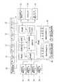
図1から図4に示すように、本発明の一実施形態によるインテリジェント型電子気圧自動調整式サスペンションシステムは、四つのエアショックアブソーバー(Air Spring)11、空気圧縮機21、電磁弁機構3、制御端4、速度センサ51、車高センサ52、水平センサ53および監視制御器6から構成される。Hereinafter, an embodiment of the present invention will be described with reference to the drawings.
As shown in FIGS. 1 to 4, an intelligent electronic pressure automatic adjustment suspension system according to an embodiment of the present invention includes four
四つのエアショックアブソーバー(Air Spring)11は、自動車の左前、右前、左後および右後に別々に装着される。本実施形態において、エアショックアブソーバー11は、ゴムまたは類似した材質から構成されたエアスプリングおよびショックアブソーバーの部品から構成される。本実施形態に使用されているエアショックアブソーバーは、図1に示すように、ベローズ型(Bellows)を呈し、移動に対応する受圧面積の変化が大きく、耐久性が優れた。かつ本実施形態は、ベローズ型のエアスプリングから構成されるエアショックアブソーバーに限らず、用途に応じて別の形のエアスプリングから構成されるエアショックアブソーバーを採用することが可能である。 Four air shock absorbers (Air Spring) 11 are separately mounted on the left front, right front, left rear, and right rear of the automobile. In the present embodiment, the
空気圧縮機21は、空気保存筒22に接続するように自動車に装着される。空気保存筒22は、筒内に保存される気圧の測定に用いられる第二圧力センサ23を有する。 The
電磁弁機構3は、自動車に装着され、第一電磁弁31、第二電磁弁32、第三電磁弁33および第四電磁弁34を有する。第一電磁弁31、第二電磁弁32、第三電磁弁33および第四電磁弁34は、吸気弁35および排気弁36を別々に有する。かつ第一電磁弁31、第二電磁弁32、第三電磁弁33および第四電磁弁34は、空気保存筒22と四つのエアショックアブソーバー11との間の充気または排気作動に用いられる。 The
第一電磁弁31、第二電磁弁32、第三電磁弁33および第四電磁弁34は第一圧力センサ12を別々に有し、四つの第一圧力センサ12は、エアショックアブソーバー11のエアスプリング内の圧力値を測定するため、四つのエアショックアブソーバー11に別々に接続される。 The first
図1に示すように、本実施形態において、第一電磁弁31、第二電磁弁32、第三電磁弁33および第四電磁弁34は、それぞれの吸気弁35および排気弁36が前後に配置され、通気管によってエアショックアブソーバー11および空気保存筒22に別々に接続される。 As shown in FIG. 1, in this embodiment, the
制御端4は、電磁弁機構3に電気的に接続され、第一マイクロ制御器41(例えばAD変換器(ADC)、発振器、SPIインターフェースおよびUART伝送インターフェースなどの機能を内蔵可能な8051ワンチップ)を有する。第一マイクロ制御器41は四つのエアショックアブソーバー11の気圧のデータを受信するため、第一圧力センサ12に電気的に接続される。制御端4の第一マイクロ制御器41は、空気保存筒22の第二圧力センサ23から伝送される空気圧縮機21内の気圧のデータを受信可能である。また制御端4は第一データ伝送ユニット42に電気的に接続される。本実施形態において、第一データ伝送ユニット42はRFモジュール(ラジオ周波モジュール)、ブルートゥースモジュールなどの無線モジュールにすることが可能である。 The
速度センサ51は、自動車の走行速度の測定に用いるため、制御端4と電気的に接続するように自動車に装着される。本実施形態において、速度センサ51は全地球測位システム(GPS)に内蔵されている速度測定機能によって速度を測定する。CPSは自動車の速度を読み取る際の利便性を有するだけでなく、様々な車種に適用でき、かつ車種によって速度センサが異なるという従来の問題を解決することが可能であるため、自動車のEMC信号を使用しないことが可能となる。 The
上述した速度センサ51は、磁気抵抗素子(MRE:Magnetic Resistance Element)によるセンサを採用することも可能である。磁力線の作用方向によって抵抗の大きさを変化させることが磁気抵抗素子によるセンサの特性であるため、多極リング磁石(Magnet Ring)の旋転速度によって磁力線が変化し、パルス信号を生じさせる。多極リング磁石を回転させることは変速ボックスに装着された伝動歯車(Drive Gear)を介して速度センサ上の受動歯車(Driven Gear)を駆動することによって自動車の速度を検知することである。 As the
車高センサ52は、車高の測定に用いるため、制御端4と電気的に接続するように自動車に装着される。車高を測定する目的は、自動車の積載重量が変わった時に車高を一定に維持しなければならない、あるいは車高を変えたい時に車高を測定する必要があるからである。そのために懸架移動を感知する車高センサを使用する必要がある。 The
本実施形態において、車高センサ52は、非接触式超音波型センサを採用する。四つの車高センサ52は車体上の四つのタイヤに近い部位に別々に装着される。超音波式車高センサは、車両の上下振動に対し、路面を基準に測定を行なう。その原理は路面に超音波を放射し、そののち反射波がセンサに返ってくる時間を測定し、それを車高に換算することである。また超音波式車高センサは、車両の上下方向のほかに路面状況を感知することも可能である。また非接触式はレーザーまたは赤外線などによって感知する方式を採用することも可能である。 In the present embodiment, the
また、上述した車高センサ52は、接触式のスライド抵抗型センサを採用することも可能である。車高センサは本体が車体端に装着され、かつリンクおよびレバーによって懸架の移動を中心軸の旋転運動に変換する。車高センサは内部が樹脂基板上に形成された抵抗体と、中心軸上に固定された電子ブラシとから構成され、かつ電子ブラシの接触によって端子間の抵抗値が中心軸の旋転角度に比例して変化するため、抵抗体に一定の電圧を加えれば、それに対応する電圧値によって回転角度(懸架移動)を検知することが可能である。車高センサ52は、抵抗式リニアスケールまたは光学式リニアスケールにすることが可能である。 Further, the above-described
上述した車高センサ52が非接触式センサを採用する場合、接触式センサを採用するよりも、装着が容易であるだけでなく、各種の車種に適用できる。 When the above-described
水平センサ53は、車体の水平状態の測定に用いるため、制御端4と電気的に接続するように自動車に装着され、かつ車体の傾斜度を測定する際、加速度センサ(図中未表示)を介して横方向からの加速度または前後方向からの加速度を検知する方法によって測定を行なうことが可能である。加速度センサは自動式または半自動式制御システムにおいて、上下方向からの加速度の検知によく使用されている。 Since the
本実施形態において、水平センサ53は圧電(Piezo)抵抗式センサまたは重力センサ(G−Sensor)を採用することが可能である。本実施形態は例として圧電(Piezo)抵抗式センサを採用する。圧電抵抗式センサは、シリコンチップにおいてマイクロ機械加工によってアーム状の梁構造を製作し、梁部に圧電抵抗を形成することによって構成される。加速度が作用する際、アーム状の梁が変形し、かつ生じた圧電抵抗効果によって抵抗を変化させる。集積回路によって抵抗の変化を信号処理すれば加速度を検知する、即ち水平に対する傾斜度を算出することが可能である。 In this embodiment, the
上述した水平センサ53は、静電容量式センサを採用することが可能である。静電容量式センサはシリコンおよびガラスから構成されるサンドイッチ構造を有し、かつシリコンをマイクロ機械加工して形成された可動電極と両側に固定される電極とによってコンデンサーを構成する。アーム状の梁を湾曲させる際、コンデンサーの静電容量が変化する。集積回路によって静電容量の変化を信号処理すれば加速度を検知する、即ち水平に対する傾斜度を算出することが可能である。 As the
制御監視端6は、第二マイクロ制御器61(例えばAD変換器(ADC)、発振器、SPIインターフェースおよびUART伝送インターフェースなどの機能を内蔵可能な8051ワンチップ)、複数の押しボタン62、第二データ伝送ユニット63および表示画面64を有する。複数の押しボタン62は別々に左前、右前、左後および右後のエアショックアブソーバー11に対応し、設定を調整することが可能である。第二データ伝送ユニット63は無線モジュール(例えばRFモジュールまたブルートゥースモジュールなど)にすることが可能である。第二データ伝送ユニット63と第一データ伝送ユニット42との間は信号伝送を行なう。本実施形態において、監視制御端6は無線方式によって制御端4に信号伝送を行なう手持型装置である。無線方式は上述したラジオ周波(RF)、ブルートゥースなどである。本実施形態は、ブルートゥース機能を有する携帯電話を介してブルートゥース伝送機能を有する制御端を制御することによって制御調整の利便性をはかることが可能である。 The
本実施形態は、無線伝送方式に限らず従来の有線伝送方式を採用することが可能である。例えば第二データ伝送ユニット63と第一データ伝送ユニット42との間は、UART技術(Universal Asynchronous Receiver Transmitter)を採用することも可能である。UARTは、マイクロプロセッサーによく使用されている通信インターフェース、例えばRS−232、RS−485などである。 The present embodiment is not limited to the wireless transmission method, and a conventional wired transmission method can be employed. For example, a UART technique (Universal Asynchronous Receiver Transmitter) can be employed between the second
上述したとおり、本発明は、監視制御端によってそれぞれの感知されたデータを統合・表示することが可能なだけでなく、監視制御端によってエアショックアブソーバーの作動を制御し、エアショックアブソーバーを自動的に調整制御する機能を果たすことが可能である。 As described above, the present invention can not only integrate and display each sensed data by the monitoring control end, but also control the operation of the air shock absorber by the monitoring control end, and automatically It is possible to fulfill the function of adjusting and controlling automatically.
言い換えれば、本発明は、走行中の自動車の状況の変化を観察する、即ち車両の積載重量、走行速度および路面状況などの走行条件に伴って車高を変化させることによってサスペンションシステムを最良の状態に維持する。かつ本発明は、ハードウェア回路にセンサを搭載する設計を採用するため、自動車の状況が変化した時、センサによって自動車の状況に対応するパラメーターを測定し、測定結果によって調整を行なうことが可能である。 In other words, the present invention observes the changes in the situation of the automobile while traveling, i.e., changes the vehicle height according to the driving conditions such as the loading weight of the vehicle, the driving speed and the road surface condition, so that the suspension system is in the best condition. To maintain. In addition, since the present invention adopts a design in which a sensor is mounted on a hardware circuit, when a vehicle situation changes, a parameter corresponding to the vehicle situation can be measured by the sensor, and adjustment can be performed according to the measurement result. is there.
図1に示すように、四つのエアショックアブソーバー11、空気圧縮機21、空気保存筒22、電磁弁機構3および電源供給器から構成されるテストベンチは、自動車のサスペンションシステムの四つのエアショックアブソーバー11をシミュレートし、かつ制御端4および監視制御端6二つの部分を有する。 As shown in FIG. 1, a test bench composed of four
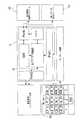
図3および図4に示すのは、制御端および監視制御端のシステムを示すブロックである。そのうち記号LF、RF、LRおよびRRは左前、右前、左後および右後のエアショックアブソーバーを表示する。図4に示すエアショックアブソーバーLF、RF、LR、RR上の記号UおよびDは、充気および排気を表示する。本システムは、第一圧力センサ12、第二圧力センサ23によって自動車のエアショックアブソーバー11内の圧力および空気保存筒22内の圧力を測定し、車高センサ52によってエアショックアブソーバーの高度を測定し、速度センサ51によって走行中の自動車の速度を測定し、水平センサ53によって走行中の自動車の状態を測定し、そののちこれらの物理エネルギーを電気信号に変換し、続いてアンプ回路によって信号を所要の範囲に変換し、そして第一マイクロ制御器41に伝送し、信号処理を行い、続いて処理された信号を第一データ伝送ユニット42(直列伝送インターフェース)から監視制御端6に伝送し、そののち信号を監視制御端6から制御端4に伝送することによって吸気弁35および排気弁36を制御し、そしてエアショックアブソーバー11に圧縮空気の注入および放出を制御することによってエアショックアブソーバー11の高度を変え、自動車の底盤の高度を制御する。 3 and 4 are blocks showing the system of the control end and the monitoring control end. Among them, the symbols LF, RF, LR and RR indicate the left front, right front, left rear and right rear air shock absorbers. The symbols U and D on the air shock absorbers LF, RF, LR, and RR shown in FIG. 4 indicate charging and exhausting. In this system, the pressure in the
図5に示すのは監視制御端6の設備の実施形態を示す模式図である。表示画面64において、上方の左右の符号094は自動車の左前および右前に位置する二つのエアショックアブソーバー11の圧力値を表示し、符号070は自動車の左後および右後に位置する二つのエアショックアブソーバー11の圧力値を表示するため、使用者は、監視制御端6の設備によって即時観察することが可能である。かつLF、RF、LRおよびRRに対応する押しボタン62によってエアショックアブソーバー11に圧力の大きさを調整する、前方の二つのタイヤを同時に上昇(F_U)または降下(F_D)させる、後方の二つのタイヤを同時に上昇(R_U)または降下(R_D)させることも可能である。 FIG. 5 is a schematic diagram showing an embodiment of the equipment of the
監視制御端6は、使用者に三組の記憶ボタン60を提供するため、使用者は仮定した状況によってパラメーターを設定し、それらを監視制御端6のメモリーに記録し、かつ必要がある場合、読み出してエアショックアブソーバー11を即時調整することが可能である。また監視制御端6は、第二データ伝送ユニット63を有する無線アンテナ65を有する。 Since the
自動車の後の座席に乗客が座っている時と、後のトランクに重い荷物が乗せてある時と、自動車が加速または減速する時、サスペンションシステムは影響を受け、車高が変化する。車体が傾斜したり底盤を損傷したりしないようにサスペンションシステムを一定の高度に維持し、第一圧力センサ12によってエアショックアブソーバー11の高度の変化を感知し、エアショックアブソーバー11の高度を自動調整すれば、車両状態に対する自動修正を達成することが可能である。 The suspension system is affected when the passenger sits in the rear seat of the car, when heavy luggage is placed on the rear trunk, and when the car accelerates or decelerates, and the vehicle height changes. The suspension system is maintained at a certain altitude so that the vehicle body is not tilted or the bottom plate is damaged, and the altitude of the
自動車が坂道を上下する際、車両は傾斜し、エアショックアブソーバー11の高度を変化させる。このとき車両の前後の中心位置に二つの水平センサ53を増設することが可能である。水平センサ53によって測定された数値と平坦な路面において測定された数値とが一致する場合、エアショックアブソーバー11の高度を変更しない。速度センサ51によって走行速度が速いと判断された場合、走行速度が速ければ速いほど車高を下げ、風の抵抗を減少させ、車両の操作の安定性を高める必要がある。また路面状況によって車高を一時的に変化させるが、その後の走行ルートに影響を与えないように、フィルタを配置し、信号をろ過することによってエアショックアブソーバー11を作動させないことが可能である。 As the automobile moves up and down the slope, the vehicle tilts and changes the altitude of the
自動車は、方向転換の際に遠心力を生じさせる。遠心力は車体を傾斜させ、傾斜した車体はタイヤの両辺と路面間との横すべりの動摩擦係数が一致しなくなるため、方向転換の過不足が生じる。このとき、水平センサを配置すれば、自動車が方向転換を行なう際に生じる傾斜度を測定・換算し、そののちエアショックアブソーバー11の高度を高めることによって方向転換の過不足を改善し、操作制御性および安全性を向上させることが可能である。 Automobiles generate centrifugal force when turning. Centrifugal force causes the vehicle body to incline, and the inclined vehicle body does not match the dynamic friction coefficient of the side slip between both sides of the tire and the road surface. At this time, if a horizontal sensor is arranged, the degree of inclination generated when the vehicle changes its direction is measured and converted, and then the altitude of the
図6に示すのは本発明によるシステム全体が自動車7に配置された状態を示す模式図である。本発明によるインテリジェント型電子気圧自動調整式サスペンションシステムが自動車に装着された場合、四つのエアショックアブソーバー11は自動車のサスペンションシステムの四箇所に別々に位置付けられる。制御端4、空気圧縮機21、空気保存筒22および電磁弁3は後のトランクに位置付けられる。監視制御端6は運転席の前方に位置付けられ、スタンドによって装着されるため、監視制御および操作の便をはかることが可能である。 FIG. 6 is a schematic diagram showing a state in which the entire system according to the present invention is arranged in the automobile 7. When the intelligent electronic pressure automatic adjustment suspension system according to the present invention is mounted on a vehicle, the four
言い換えれば、本発明においてのエアショックアブソーバーは、ゴムチャンバーの内部において空気を圧縮する反作用力によってスプリングの作用を獲得し、かつ従来の鋼鉄製のコイル状スプリングの代わりに自動車に配置するため、従来の金属スプリングと比べて次のような長所を有する。 In other words, the air shock absorber according to the present invention acquires the action of the spring by the reaction force that compresses air inside the rubber chamber, and is arranged in the automobile instead of the conventional steel coiled spring. Compared to the metal springs, it has the following advantages.
イ)、エアスプリングの充気および排気によってスプリング常数K値を任意に変更し、かつダンビング値C/Tを調整可能なダンビング装置との組み合せによって乗り心地を大幅に改善することが可能である。
ロ)、スプリングの特性が基本的に非線形であるため、設計の際に様々な設定を選ぶことが容易である。
ハ)、スプリング常数と空気圧とは正比例し、積載重量の変化にかかわらず固有振動数が概ね一致するため、乗り心地が安定する。
ニ)、車高調整機構の組立が容易であり、かつ積載重量の変化にかかわらず車高を一定に維持したり高度を任意に調整したりすることが可能である。B) It is possible to significantly improve the ride comfort by combining with a damping device that can arbitrarily change the spring constant K value by charging and exhausting the air spring and adjust the damping value C / T.
B) Since the spring characteristics are basically non-linear, it is easy to select various settings during design.
C) The spring constant and the air pressure are directly proportional, and the natural frequency is almost the same regardless of changes in the loaded weight, so that the ride comfort is stable.
D) The assembly of the vehicle height adjustment mechanism is easy, and the vehicle height can be maintained constant or the altitude can be arbitrarily adjusted regardless of changes in the load weight.
上述したとおり、本発明は速度センサ、水平センサ(必要に応じて配置するか否かを決める)、車高センサ、圧力センサおよびエアショックアブソーバーを組み合せ、エアショックアブソーバーが位置した地面状態及び車体状態に応じてエアショックアブソーバーを即時に自動調整することによって運転者および乗客に快適な乗り心地を与え、個人の操作の習慣に応じて良好の操作、制御及び設定を提供することが可能である。 As described above, the present invention is a combination of a speed sensor, a horizontal sensor (determining whether or not to arrange as necessary), a vehicle height sensor, a pressure sensor, and an air shock absorber, and a ground state and a vehicle body state where the air shock absorber is located. Accordingly, it is possible to provide a comfortable ride to the driver and passengers by immediately and automatically adjusting the air shock absorber according to the vehicle, and to provide good operation, control and setting according to the personal operation habits.
積載重量の比較的大きい貨物車、商用自動車およびトラックなどに対し、本発明による技術は、車両の積載重量が平均しなかった時、スプリングショックアブソーバーの高度を適切に調整することによって車体を安定させ、傾斜させないように維持することが可能であるため、ショックアブソーバーの使用寿命が確実に長くなり、かつ車体が衝撃を受けて損傷してしまうとう現象が発生しない。 For freight vehicles, commercial vehicles, trucks, etc., which have a relatively large load weight, the technology according to the present invention stabilizes the vehicle body by appropriately adjusting the height of the spring shock absorber when the vehicle load weight is not averaged. Since it is possible to maintain the shock absorber so as not to be inclined, the service life of the shock absorber is surely increased, and the phenomenon that the vehicle body is damaged by impact is not generated.
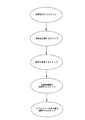
図7に示すのは本発明によるインテリジェント型電子気圧自動調整式サスペンションシステムの操作方法を示す模式図である。図8および図9に示すのは制御端および監視制御端のプロセスを示す模式図である。本発明は次のステップを含む。 FIG. 7 is a schematic diagram showing a method for operating the intelligent electronic barometric pressure automatic adjustment suspension system according to the present invention. FIG. 8 and FIG. 9 are schematic diagrams showing processes of the control end and the monitoring control end. The present invention includes the following steps.
配置を行なうステップは、制御端4および監視制御端6を配置し、制御端4と監視制御端6との間に信号伝送機能を有する。 In the step of arranging, the
信号を収集するステップは、制御端4によって制御を行い、速度センサ51によって自動車の走行速度を測定し、水平センサ53によって車体の水平状態を測定し、車高センサ52によって車高を測定し、四つの第一圧力センサ12によって四つのエアショックアブソーバー11内の圧力を測定する。 In the step of collecting signals, control is performed by the
信号を伝送するステップは、前述したセンサによって測定された走行速度、水平状態、車高および圧力データを監視制御端6に伝送し、コードを解読し、解読結果を監視制御端6の表示画面64に表示する。 In the step of transmitting a signal, the traveling speed, the horizontal state, the vehicle height and the pressure data measured by the above-described sensor are transmitted to the
電磁弁機構3を制御するステップは、監視制御端6上の押しボタン62を押して入力するか、第二マイクロ制御器62を介してそれぞれのエアショックアブソーバー11の最適な高度を自動計算し、そして調整待ちのデータをコードに変換し、制御端4に伝送する。かつ予め手動で関連があるデータを設定し、メモリーに保存することによって、使用者が必要に応じ設定値を読み取ることを可能にする。 The step of controlling the
エアショックアブソーバー11の高度を調整するステップは、制御端4によってコードを解読し、解読された信号によってエアショックアブソーバー11と互いに対応する吸気弁35および排気弁36を制御し、エアショックアブソーバー11に加圧気体を充填または放出することによってエアショックアブソーバー11の高度を変更する。 In the step of adjusting the altitude of the
上述したのは本発明によるサスペンションシステムの操作方法である。操作過程において、それぞれのセンサによって必要なデータを獲得可能であるほかに、監視制御端を介して自動車の状態および路面状況を観察し、手動または監視制御端6または制御端4などのいずれか一つによってそれぞれのエアショックアブソーバーに充気または排気を調整することを可能にすることが主な目的である。 What has been described above is a method of operating a suspension system according to the present invention. In the operation process, necessary data can be acquired by each sensor, and the state of the vehicle and the road surface condition are observed through the monitoring control terminal, and either one of the manual control or the
通常の状態の場合、コンピューターによって制御端4を介して関連があるパラメーターに測定、収集および次の設定を行なえば使用の便をはかることが可能である。運転者の習慣が比較的特別である場合、手動で設定を行なうことによって運転者の習慣に応えることも可能である。 In the normal state, it is possible to use the computer by measuring, collecting, and setting the related parameters via the
図8に示すように、システムが起動される際、初期化設定を行なう、例えば無線モジュールの初期化設定、車高初期化の調整などを行なう。初期化が完了した後、それぞれのセンサによって測定された関連があるデータ、例えば四つの圧力センサの圧力値、速度信号、水平信号および四つの高度センサの信号を連続読取し、そののち、それらの測定された信号を統合し、コードに変換し、第一伝送ユニットに伝送する。続いて第二データ伝送ユニットによって受信されたデータにチェックサム(chesksum)を行い、データが正確であるか否かを判断し、そののち四つのエアショックアブソーバーに対応するエアスプリングに充気または排気指示を発することによってエアスプリングの高度を制御調整する。図8に示すプロセスは、指示を受ける方式を採用することが特徴の一つであるため、高度信号を受信する際に誤りが発生し、制御を誤ってしまうという事態を避けることが可能である。 As shown in FIG. 8, when the system is started, initialization settings are performed, for example, initialization settings for wireless modules, adjustment of vehicle height initialization, and the like. After initialization is complete, the relevant data measured by each sensor, for example, the pressure values of the four pressure sensors, the velocity signal, the horizontal signal and the signals of the four altitude sensors are read continuously, after which The measured signals are integrated, converted into a code, and transmitted to the first transmission unit. Subsequently, a checksum is performed on the data received by the second data transmission unit to determine whether the data is correct, and then the air springs corresponding to the four air shock absorbers are charged or exhausted. Control and adjust air spring altitude by issuing instructions. Since the process shown in FIG. 8 employs a method of receiving an instruction, it is possible to avoid a situation in which an error occurs when an altitude signal is received and control is mistaken. .
図9に示すように、システムが起動される際、初期化、例えば無線モジュールの初期化、液晶ディスプレイ(表示画面)の初期化などを行い、そののち押しボタンに設定を行なう。押しボタンが手動方式に設定される場合、使用者が押した押しボタンによってそれぞれのエアショックアブソーバーのエアスプリングの充気または排気作動を制御する。逆に自動調整方式を選ぶ場合、読み取った走行データによってエアスプリングを最良の状態に調整する。同時に液晶ディスプレイ(表示画面)は必要に応じ、自動車に関連がある走行データを表示する。 As shown in FIG. 9, when the system is activated, initialization, for example, initialization of a wireless module, initialization of a liquid crystal display (display screen), and the like are performed, and then a push button is set. When the push button is set to the manual method, the charging or exhausting operation of the air spring of each air shock absorber is controlled by the push button pushed by the user. Conversely, when the automatic adjustment method is selected, the air spring is adjusted to the best state based on the read travel data. At the same time, the liquid crystal display (display screen) displays driving data related to the automobile as required.
11:エアショックアブソーバー、 12:第一圧力センサ、 21:空気圧縮機、 22:空気保存筒、 23:第二圧力センサ、 3:電磁弁機構、 31:第一電磁弁、32:第二電磁弁、 33:第三電磁弁、 34:第四電磁弁、 35:吸気弁、36:排気弁、 4:制御端、 41:第一マイクロ制御器、 42:第一データ伝送ユニット、 51:速度センサ、 52:車高センサ、 53:水平センサ、 6:監視制御端、 60:記録ボタン、 61:第二マイクロ制御器、 62:押しボタン、 63:第二データ伝送ユニット、 64:表示画面、 65:無線アンテナ、 7:自動車11: air shock absorber, 12: first pressure sensor, 21: air compressor, 22: air storage cylinder, 23: second pressure sensor, 3: solenoid valve mechanism, 31: first solenoid valve, 32: second solenoid Valve 33: third solenoid valve 34: fourth solenoid valve 35: intake valve 36: exhaust valve 4: control end 41: first microcontroller 42: first data transmission unit 51: speed Sensor: 52: Vehicle height sensor, 53: Horizontal sensor, 6: Monitoring control end, 60: Record button, 61: Second microcontroller, 62: Push button, 63: Second data transmission unit, 64: Display screen, 65: Radio antenna, 7: Automobile
Claims (5)
Translated fromJapanese空気保存筒と接続するように自動車に装着される空気圧縮機と、
自動車に装着され、第一電磁弁、第二電磁弁、第三電磁弁および第四電磁弁を有し、前記第一電磁弁、前記第二電磁弁、前記第三電磁弁および前記第四電磁弁は、吸気弁および排気弁を別々に有し、かつ前記空気保存筒と四つの前記エアショックアブソーバーとの間の充気または排気作動に用いられ、かつ前記第一電磁弁、前記第二電磁弁、前記第三電磁弁および前記第四電磁弁は第一圧力センサーを別々に有し、四つの前記第一圧力センサーは、圧力値を測量するため四つの前記エアショックアブソーバーに別々に接続される電磁弁機構と、
前記電磁弁機構に電気的に接続され、第一マイクロ制御器および第一データ伝送ユニットを有し、前記第一マイクロ制御器は前記第一圧力センサーに電気的に接続される制御端と、
自動車の走行速度の測定に用いるため、前記制御端と電気的に接続するように自動車に装着される少なくとも一つの速度センサーと、
車高の測定に用いるため、前記制御端と電気的に接続するように自動車に装着される少なくとも一つの車高センサーと、
第二マイクロ制御器、複数の押しボタン、第二データ伝送ユニットおよび表示画面を有し、かつ前記制御端との間に信号伝送機能を有し、前記複数の押しボタンは別々に左前、右前、左後および右後の前記エアショックアブソーバーに対応し設定を調整可能であり、前記第二データ伝送ユニットと前記第一データ伝送ユニットとの間は信号伝送を行う制御監視端と、を備え、
前記監視制御端は、前述したセンサーによって測定された走行速度、車高、圧力データを受信し、コード解読を行い、解読結果を前記表示画面に表示し、
前記監視制御端は、前記押しボタンを押して入力するか、又は、前記第二マイクロ制御器を介してそれぞれのエアショックアブソーバーの最適な高度を自動計算し、そして調整待ちのデータをコードに変換し、前記制御端に伝送することによって前記電磁弁機構を制御し、
前記制御端は、コードを解読した後、解読した信号によって前記エアショックアブソーバーと互いに対応する吸気弁および排気弁を制御し、前記エアショックアブソーバーに加圧気体を充填または放出することによって前記エアショックアブソーバーの高度を変更することを特徴とするインテリジェント型電子気圧自動調整式サスペンションシステム。Four air shock absorbers mounted separately on the left front, right front, left rear and right rear suspension systems of the car,
An air compressor mounted on the automobile to connect to the air storage cylinder;
A first solenoid valve, a second solenoid valve, a third solenoid valve, and a fourth solenoid valve, which are mounted on an automobile, include the first solenoid valve, the second solenoid valve, the third solenoid valve, and the fourth solenoid valve. The valve has an intake valve and an exhaust valve separately, and is used for charging or exhausting operation between the air storage cylinder and the four air shock absorbers, and the first electromagnetic valve and the second electromagnetic valve The valve, the third solenoid valve and the fourth solenoid valve have a first pressure sensor separately, and the four first pressure sensors are separately connected to the four air shock absorbers for measuring pressure values. A solenoid valve mechanism,
A control end electrically connected to the solenoid valve mechanism, having a first microcontroller and a first data transmission unit, the first microcontroller being electrically connected to the first pressure sensor;
At least one speed sensor mounted on the vehicle for electrical connection with the control end for use in measuring the running speed of the vehicle;
At least one vehicle height sensor mounted on the vehicle for electrical connection with the control end for use in vehicle height measurement;
A second microcontroller, a plurality of push buttons, a second data transmission unit and a display screen, and a signal transmission function between the control end, the plurality of push buttons are separately left front, right front, It is possible to adjust the setting corresponding to the air shock absorber on the left rear and the right rear, and a control monitoring end that performs signal transmission between the second data transmission unit and the first data transmission unit,
The monitoring control terminal receives the traveling speed, vehicle height, and pressure data measured by the sensor described above, performs code decoding, and displays the decoding result on the display screen,
The supervisory control end either presses the push button to input, or automatically calculates the optimum altitude of each air shock absorber via the second microcontroller, and converts the data waiting for adjustment into a code. , Controlling the solenoid valve mechanism by transmitting to the control end,
The control end, after decoding the code, controls the intake valve and the exhaust valve corresponding to the air shock absorber according to the decoded signal, and fills or discharges the pressurized gas to the air shock absorber to discharge the air shock. An intelligent electronic barometric pressure adjustment suspension system that changes the altitude of the absorber.
Priority Applications (1)
| Application Number | Priority Date | Filing Date | Title |
|---|---|---|---|
| JP2009137947AJP2010284982A (en) | 2009-06-09 | 2009-06-09 | Intelligent type electronic air pressure automatically adjusting suspension system |
Applications Claiming Priority (1)
| Application Number | Priority Date | Filing Date | Title |
|---|---|---|---|
| JP2009137947AJP2010284982A (en) | 2009-06-09 | 2009-06-09 | Intelligent type electronic air pressure automatically adjusting suspension system |
Publications (1)
| Publication Number | Publication Date |
|---|---|
| JP2010284982Atrue JP2010284982A (en) | 2010-12-24 |
Family
ID=43541047
Family Applications (1)
| Application Number | Title | Priority Date | Filing Date |
|---|---|---|---|
| JP2009137947APendingJP2010284982A (en) | 2009-06-09 | 2009-06-09 | Intelligent type electronic air pressure automatically adjusting suspension system |
Country Status (1)
| Country | Link |
|---|---|
| JP (1) | JP2010284982A (en) |
Cited By (11)
| Publication number | Priority date | Publication date | Assignee | Title |
|---|---|---|---|---|
| CN104553659A (en)* | 2014-10-10 | 2015-04-29 | 青岛浩釜铭车辆科技有限公司 | Electrically controlled air suspension height adjustment control system |
| WO2016171425A1 (en)* | 2015-04-22 | 2016-10-27 | 고재원 | Vehicle shock absorber control system having individual pneumatic pumps |
| CN106945478A (en)* | 2017-03-31 | 2017-07-14 | 上海威曼汽车零部件有限公司 | A kind of air suspension uninstall protection device for being used to protect a certain axle tire |
| CN109196193A (en)* | 2016-05-27 | 2019-01-11 | 伊维克斯私人有限公司 | Control system for valve |
| CN109677227A (en)* | 2019-01-14 | 2019-04-26 | 南京航空航天大学 | A kind of body gesture regulating system and method based on air spring |
| CN110884315A (en)* | 2019-10-28 | 2020-03-17 | 科曼车辆部件系统(苏州)有限公司 | An intelligent electronically controlled air suspension system for commercial vehicles |
| JP2020537609A (en)* | 2017-09-28 | 2020-12-24 | サン−ゴバン パフォーマンス プラスチックス パンプス ゲゼルシャフト ミット ベシュレンクテル ハフツング | Suspension assembly and its manufacturing and usage |
| CN114312197A (en)* | 2022-01-05 | 2022-04-12 | 一汽解放汽车有限公司 | Vehicle driving antiskid control system, device and control method |
| CN114829169A (en)* | 2019-11-21 | 2022-07-29 | 特斯拉公司 | Adjustable suspension for a vehicle |
| CN115791217A (en)* | 2023-01-28 | 2023-03-14 | 北京理工大学前沿技术研究院 | Automobile electronic control suspension simulation system and method |
| CN116852932A (en)* | 2023-07-07 | 2023-10-10 | 山东泰展机电科技股份有限公司 | Intelligent distribution terminal and air pump with same |
Citations (5)
| Publication number | Priority date | Publication date | Assignee | Title |
|---|---|---|---|---|
| JPH0331425U (en)* | 1989-08-03 | 1991-03-27 | ||
| JPH03135811A (en)* | 1987-09-04 | 1991-06-10 | Toyota Motor Corp | Electronic control suspension device |
| JP2005063024A (en)* | 2003-08-08 | 2005-03-10 | Mitsubishi Fuso Truck & Bus Corp | Failure diagnostic device |
| JP2005125907A (en)* | 2003-10-23 | 2005-05-19 | Mitsubishi Fuso Truck & Bus Corp | Vehicle height adjusting device |
| US20070255466A1 (en)* | 2006-04-28 | 2007-11-01 | Shui-Chuan Chiao | Daming adjusting/controlling system for wireless adjustment of shock-absorbers for vehicle |
- 2009
- 2009-06-09JPJP2009137947Apatent/JP2010284982A/enactivePending
Patent Citations (5)
| Publication number | Priority date | Publication date | Assignee | Title |
|---|---|---|---|---|
| JPH03135811A (en)* | 1987-09-04 | 1991-06-10 | Toyota Motor Corp | Electronic control suspension device |
| JPH0331425U (en)* | 1989-08-03 | 1991-03-27 | ||
| JP2005063024A (en)* | 2003-08-08 | 2005-03-10 | Mitsubishi Fuso Truck & Bus Corp | Failure diagnostic device |
| JP2005125907A (en)* | 2003-10-23 | 2005-05-19 | Mitsubishi Fuso Truck & Bus Corp | Vehicle height adjusting device |
| US20070255466A1 (en)* | 2006-04-28 | 2007-11-01 | Shui-Chuan Chiao | Daming adjusting/controlling system for wireless adjustment of shock-absorbers for vehicle |
Cited By (18)
| Publication number | Priority date | Publication date | Assignee | Title |
|---|---|---|---|---|
| CN104553659A (en)* | 2014-10-10 | 2015-04-29 | 青岛浩釜铭车辆科技有限公司 | Electrically controlled air suspension height adjustment control system |
| CN104553659B (en)* | 2014-10-10 | 2016-07-20 | 青岛浩釜铭车辆科技有限公司 | Electronic control air suspension height adjustable controls device |
| WO2016171425A1 (en)* | 2015-04-22 | 2016-10-27 | 고재원 | Vehicle shock absorber control system having individual pneumatic pumps |
| CN109196193A (en)* | 2016-05-27 | 2019-01-11 | 伊维克斯私人有限公司 | Control system for valve |
| CN106945478A (en)* | 2017-03-31 | 2017-07-14 | 上海威曼汽车零部件有限公司 | A kind of air suspension uninstall protection device for being used to protect a certain axle tire |
| JP2022017370A (en)* | 2017-09-28 | 2022-01-25 | サン-ゴバン パフォーマンス プラスチックス パンプス ゲゼルシャフト ミット ベシュレンクテル ハフツング | Suspension assembly and manufacturing method and usage thereof |
| JP2020537609A (en)* | 2017-09-28 | 2020-12-24 | サン−ゴバン パフォーマンス プラスチックス パンプス ゲゼルシャフト ミット ベシュレンクテル ハフツング | Suspension assembly and its manufacturing and usage |
| CN109677227A (en)* | 2019-01-14 | 2019-04-26 | 南京航空航天大学 | A kind of body gesture regulating system and method based on air spring |
| CN109677227B (en)* | 2019-01-14 | 2023-09-26 | 南京航空航天大学 | Vehicle body posture adjusting system and method based on air spring |
| CN110884315A (en)* | 2019-10-28 | 2020-03-17 | 科曼车辆部件系统(苏州)有限公司 | An intelligent electronically controlled air suspension system for commercial vehicles |
| CN114829169A (en)* | 2019-11-21 | 2022-07-29 | 特斯拉公司 | Adjustable suspension for a vehicle |
| JP2023502273A (en)* | 2019-11-21 | 2023-01-23 | テスラ,インコーポレイテッド | adjustable vehicle suspension |
| US12151673B2 (en) | 2019-11-21 | 2024-11-26 | Tesla, Inc. | Adjustable suspension for a vehicle |
| JP7730813B2 (en) | 2019-11-21 | 2025-08-28 | テスラ,インコーポレイテッド | Adjustable vehicle suspension |
| CN114312197A (en)* | 2022-01-05 | 2022-04-12 | 一汽解放汽车有限公司 | Vehicle driving antiskid control system, device and control method |
| CN114312197B (en)* | 2022-01-05 | 2023-12-08 | 一汽解放汽车有限公司 | Vehicle driving anti-skid control system, device and control method |
| CN115791217A (en)* | 2023-01-28 | 2023-03-14 | 北京理工大学前沿技术研究院 | Automobile electronic control suspension simulation system and method |
| CN116852932A (en)* | 2023-07-07 | 2023-10-10 | 山东泰展机电科技股份有限公司 | Intelligent distribution terminal and air pump with same |
Similar Documents
| Publication | Publication Date | Title |
|---|---|---|
| JP2010284982A (en) | Intelligent type electronic air pressure automatically adjusting suspension system | |
| US8113521B2 (en) | Intelligent electronic air suspension system that automatically adjusts its air pressure | |
| US7398668B2 (en) | Weight sensing system and method for vehicles with non-fluid springs | |
| CN110103660B (en) | Method, system, equipment and storage medium for dynamic compensation of automobile suspension | |
| US12275285B2 (en) | Method for determining an axle load on a mechanically suspended vehicle | |
| US8521361B2 (en) | Ride height control system and method for controlling load distribution at target ride height in a vehicle suspension system | |
| JP2010510926A (en) | Vehicle load status display system | |
| US4677263A (en) | Air spring position switch | |
| CN202782852U (en) | Vehicle load self measuring device and car | |
| CN101905694B (en) | Intelligent electronic self-adjusting pneumatic suspension system | |
| US7142102B2 (en) | Weight overload warning system | |
| US8437911B2 (en) | Ride height control system and method for controlling load distribution at target ride height in a vehicle suspension system | |
| JP2007084037A (en) | Suspension device | |
| TWI621545B (en) | Suspension control module, suspension system, vehicle, and suspension control method | |
| TW201041760A (en) | Intelligent electronic automatic air-pressure adjusting suspension system and its operation method | |
| JP4832179B2 (en) | Truck load detection device | |
| CN101387542A (en) | Deadweight detection device for whole vehicle and detecting method thereof based on oil gas or air spring | |
| TWM546323U (en) | Suspension control module, suspension system, and vehicle | |
| CN110612221A (en) | Method for determining the ageing of a vehicle suspension | |
| JP2005088874A (en) | Travelable distance estimation device | |
| KR20140028955A (en) | Sensor for measuring height of vehicle, apparatus for measuring height of vehicle, active electronic control system for air suspension of commercial vehicle | |
| CN202847371U (en) | Device capable of actively detecting and controlling automotive suspension | |
| GB2491450A (en) | A method for calibrating an adaptive chassis system of a motorvehicle | |
| CN101387541A (en) | Deadweight detection device for whole vehicle and detecting method thereof | |
| CN115014672B (en) | Device, system and method for monitoring rigidity of spiral spring |
Legal Events
| Date | Code | Title | Description |
|---|---|---|---|
| A977 | Report on retrieval | Effective date:20110907 Free format text:JAPANESE INTERMEDIATE CODE: A971007 | |
| A131 | Notification of reasons for refusal | Free format text:JAPANESE INTERMEDIATE CODE: A131 Effective date:20110916 | |
| A02 | Decision of refusal | Free format text:JAPANESE INTERMEDIATE CODE: A02 Effective date:20120306 |