JP2010283442A - Mobile terminal device - Google Patents
Mobile terminal deviceDownload PDFInfo
- Publication number
- JP2010283442A JP2010283442AJP2009133135AJP2009133135AJP2010283442AJP 2010283442 AJP2010283442 AJP 2010283442AJP 2009133135 AJP2009133135 AJP 2009133135AJP 2009133135 AJP2009133135 AJP 2009133135AJP 2010283442 AJP2010283442 AJP 2010283442A
- Authority
- JP
- Japan
- Prior art keywords
- terminal device
- operation unit
- mobile terminal
- unit
- image
- Prior art date
- Legal status (The legal status is an assumption and is not a legal conclusion. Google has not performed a legal analysis and makes no representation as to the accuracy of the status listed.)
- Withdrawn
Links
Images


Classifications
- H—ELECTRICITY
- H04—ELECTRIC COMMUNICATION TECHNIQUE
- H04M—TELEPHONIC COMMUNICATION
- H04M1/00—Substation equipment, e.g. for use by subscribers
- H04M1/02—Constructional features of telephone sets
- H04M1/0202—Portable telephone sets, e.g. cordless phones, mobile phones or bar type handsets
- H04M1/0206—Portable telephones comprising a plurality of mechanically joined movable body parts, e.g. hinged housings
- H04M1/0208—Portable telephones comprising a plurality of mechanically joined movable body parts, e.g. hinged housings characterized by the relative motions of the body parts
- H04M1/0214—Foldable telephones, i.e. with body parts pivoting to an open position around an axis parallel to the plane they define in closed position
- G—PHYSICS
- G06—COMPUTING OR CALCULATING; COUNTING
- G06F—ELECTRIC DIGITAL DATA PROCESSING
- G06F3/00—Input arrangements for transferring data to be processed into a form capable of being handled by the computer; Output arrangements for transferring data from processing unit to output unit, e.g. interface arrangements
- G06F3/01—Input arrangements or combined input and output arrangements for interaction between user and computer
- G06F3/02—Input arrangements using manually operated switches, e.g. using keyboards or dials
- G06F3/023—Arrangements for converting discrete items of information into a coded form, e.g. arrangements for interpreting keyboard generated codes as alphanumeric codes, operand codes or instruction codes
- G06F3/0233—Character input methods
- G06F3/0236—Character input methods using selection techniques to select from displayed items
- G—PHYSICS
- G06—COMPUTING OR CALCULATING; COUNTING
- G06F—ELECTRIC DIGITAL DATA PROCESSING
- G06F3/00—Input arrangements for transferring data to be processed into a form capable of being handled by the computer; Output arrangements for transferring data from processing unit to output unit, e.g. interface arrangements
- G06F3/01—Input arrangements or combined input and output arrangements for interaction between user and computer
- G06F3/048—Interaction techniques based on graphical user interfaces [GUI]
- G06F3/0481—Interaction techniques based on graphical user interfaces [GUI] based on specific properties of the displayed interaction object or a metaphor-based environment, e.g. interaction with desktop elements like windows or icons, or assisted by a cursor's changing behaviour or appearance
- G06F3/0482—Interaction with lists of selectable items, e.g. menus
- G—PHYSICS
- G06—COMPUTING OR CALCULATING; COUNTING
- G06F—ELECTRIC DIGITAL DATA PROCESSING
- G06F3/00—Input arrangements for transferring data to be processed into a form capable of being handled by the computer; Output arrangements for transferring data from processing unit to output unit, e.g. interface arrangements
- G06F3/01—Input arrangements or combined input and output arrangements for interaction between user and computer
- G06F3/048—Interaction techniques based on graphical user interfaces [GUI]
- G06F3/0487—Interaction techniques based on graphical user interfaces [GUI] using specific features provided by the input device, e.g. functions controlled by the rotation of a mouse with dual sensing arrangements, or of the nature of the input device, e.g. tap gestures based on pressure sensed by a digitiser
- G06F3/0488—Interaction techniques based on graphical user interfaces [GUI] using specific features provided by the input device, e.g. functions controlled by the rotation of a mouse with dual sensing arrangements, or of the nature of the input device, e.g. tap gestures based on pressure sensed by a digitiser using a touch-screen or digitiser, e.g. input of commands through traced gestures
- G06F3/04883—Interaction techniques based on graphical user interfaces [GUI] using specific features provided by the input device, e.g. functions controlled by the rotation of a mouse with dual sensing arrangements, or of the nature of the input device, e.g. tap gestures based on pressure sensed by a digitiser using a touch-screen or digitiser, e.g. input of commands through traced gestures for inputting data by handwriting, e.g. gesture or text
- G—PHYSICS
- G06—COMPUTING OR CALCULATING; COUNTING
- G06F—ELECTRIC DIGITAL DATA PROCESSING
- G06F3/00—Input arrangements for transferring data to be processed into a form capable of being handled by the computer; Output arrangements for transferring data from processing unit to output unit, e.g. interface arrangements
- G06F3/01—Input arrangements or combined input and output arrangements for interaction between user and computer
- G06F3/048—Interaction techniques based on graphical user interfaces [GUI]
- G06F3/0487—Interaction techniques based on graphical user interfaces [GUI] using specific features provided by the input device, e.g. functions controlled by the rotation of a mouse with dual sensing arrangements, or of the nature of the input device, e.g. tap gestures based on pressure sensed by a digitiser
- G06F3/0488—Interaction techniques based on graphical user interfaces [GUI] using specific features provided by the input device, e.g. functions controlled by the rotation of a mouse with dual sensing arrangements, or of the nature of the input device, e.g. tap gestures based on pressure sensed by a digitiser using a touch-screen or digitiser, e.g. input of commands through traced gestures
- G06F3/04886—Interaction techniques based on graphical user interfaces [GUI] using specific features provided by the input device, e.g. functions controlled by the rotation of a mouse with dual sensing arrangements, or of the nature of the input device, e.g. tap gestures based on pressure sensed by a digitiser using a touch-screen or digitiser, e.g. input of commands through traced gestures by partitioning the display area of the touch-screen or the surface of the digitising tablet into independently controllable areas, e.g. virtual keyboards or menus
- H—ELECTRICITY
- H04—ELECTRIC COMMUNICATION TECHNIQUE
- H04M—TELEPHONIC COMMUNICATION
- H04M1/00—Substation equipment, e.g. for use by subscribers
- H04M1/72—Mobile telephones; Cordless telephones, i.e. devices for establishing wireless links to base stations without route selection
- H04M1/724—User interfaces specially adapted for cordless or mobile telephones
- H04M1/72466—User interfaces specially adapted for cordless or mobile telephones with selection means, e.g. keys, having functions defined by the mode or the status of the device
- H—ELECTRICITY
- H04—ELECTRIC COMMUNICATION TECHNIQUE
- H04M—TELEPHONIC COMMUNICATION
- H04M1/00—Substation equipment, e.g. for use by subscribers
- H04M1/02—Constructional features of telephone sets
- H04M1/22—Illumination; Arrangements for improving the visibility of characters on dials
- H—ELECTRICITY
- H04—ELECTRIC COMMUNICATION TECHNIQUE
- H04M—TELEPHONIC COMMUNICATION
- H04M2250/00—Details of telephonic subscriber devices
- H04M2250/22—Details of telephonic subscriber devices including a touch pad, a touch sensor or a touch detector
Landscapes
- Engineering & Computer Science (AREA)
- General Engineering & Computer Science (AREA)
- Theoretical Computer Science (AREA)
- Human Computer Interaction (AREA)
- Physics & Mathematics (AREA)
- General Physics & Mathematics (AREA)
- Signal Processing (AREA)
- Computer Networks & Wireless Communication (AREA)
- User Interface Of Digital Computer (AREA)
- Telephone Function (AREA)
- Position Input By Displaying (AREA)
- Telephone Set Structure (AREA)
Abstract
Translated fromJapaneseDescription
Translated fromJapanese本発明は、携帯端末装置に関し、特に、互いに異なる2種類の操作部を備える携帯端末装置に関する。 The present invention relates to a mobile terminal device, and more particularly to a mobile terminal device including two different types of operation units.
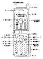
近年、多機能化された携帯電話の操作を容易にするためのユーザインターフェースが開発されている。例えば、図14に示す携帯電話装置KSは、折畳み式の携帯電話装置本体Hに、キー入力を行う操作部1と、電話相手の番号や電話帳情報などを表示する表示部2と、マイク3と、レシーバ4と、本体上部に設けたアンテナ5とを備えている。 In recent years, user interfaces for facilitating the operation of multifunctional mobile phones have been developed. For example, a mobile phone device KS shown in FIG. 14 has a foldable mobile phone device main body H, an operation unit 1 for performing key input, a display unit 2 for displaying a telephone partner number, phone book information, and the like, and a
この携帯電話装置KSは、表示部2に操作部表示6(操作部1をビジュアル的に表示したもの)を行ない、例えば、表示部2に表示された「電話をかける」を反転表示し、また操作部表示6に表示された「開始キー」7をマーカー表示し、視覚認識可能(ビジュアル的)に表示するので、高齢者や児童等であっても、次に操作すべき内容を理解でき、その操作に必要なキーを容易に認識することができる。ただし、表示部2がタッチパネルであるとの記載は無い(例えば、特許文献1参照)。 The mobile phone device KS performs an operation unit display 6 (a visual display of the operation unit 1) on the display unit 2, for example, reverses the display of “calling” displayed on the display unit 2, and The “start key” 7 displayed on the operation unit display 6 is displayed as a marker so that it can be visually recognized (visually), so even an elderly person or a child can understand the contents to be operated next, Keys necessary for the operation can be easily recognized. However, there is no description that the display part 2 is a touch panel (for example, refer patent document 1).
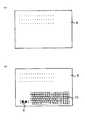
一方、周囲の明るさに応じて、物理キーに対応したソフトキーを自動表示し、携帯電話にも適用できる電子機器が知られている。図15は、この電子機器により、外部光量を検出し、周囲の明るさに応じて、物理キーに対応したソフトウェアキーボードを表示画面上に自動的に表示した表示画面8を示す図である。 On the other hand, electronic devices that automatically display soft keys corresponding to physical keys according to ambient brightness and can be applied to mobile phones are also known. FIG. 15 is a diagram showing a
図15(a)は、表示画面8上にソフトキー表示が何もなされていない表示画面例である。そして、図15(b)は、外部光量レベルが所定の閾値レベル以下のため、表示画面8上にソフトキー群10と電源スイッチソフトキー9が表示されている表示画面例である。ただし、ソフトキーを表示したときは、電子機器本体に設けられた物理キーは使用不可となる(例えば、特許文献2参照)。 FIG. 15A is an example of a display screen on which no soft key is displayed on the
しかしながら、特許文献1に記載された携帯電話装置は、キーの意味が一意に決まっていて、ある画面で有効なキーを表示するような操作ナビゲーション用途に限定されている。すなわち、物理キー(機械式のキー)とソフトキー(タッチパネルのキー;タッチキー)の関係が固定されており連動することがない。 However, the cellular phone device described in Patent Document 1 is limited to operation navigation applications in which the meaning of the key is uniquely determined and an effective key is displayed on a certain screen. That is, the relationship between a physical key (mechanical key) and a soft key (touch panel key; touch key) is fixed and does not interlock.
また、特許文献2に記載された電子機器は、タッチキーか物理キーを排他で利用し、暗いところではLCD(表示画面)のソフトキーのみ、明るいところでは物理キーのみがそれぞれ操作可能であり、両者が操作可能になっていない。この場合、タッチパネルのみでは、感覚的な(大雑把な)操作はやりやすいが、細かい微調整のような操作には向かない。物理キーはその逆が言える。 The electronic device described in Patent Document 2 exclusively uses touch keys or physical keys, and can operate only LCD (display screen) soft keys in dark places and only physical keys in bright places. Both are not operational. In this case, a sensory (rough) operation is easy to perform with only the touch panel, but it is not suitable for operations such as fine adjustment. The opposite is true for physical keys.
本発明は、上記従来の事情に鑑みてなされたものであって、2種類の操作部が直感的に連動しているということが分かるような画面表示を行い、2種類の操作部(例えば、タッチパネルと物理キー)を連携させる携帯端末装置を提供する。 The present invention has been made in view of the above-described conventional circumstances, and performs screen display so that it can be understood that two types of operation units are intuitively linked, and two types of operation units (for example, Provided is a portable terminal device that links a touch panel and a physical key.
本発明の携帯端末装置は、画像を表示する画像領域と操作キーを表示する操作領域とを有する第1の操作部と、前記第1の操作部の前記操作領域と連動する第2の操作部と、を備える。 A portable terminal device according to the present invention includes a first operation unit having an image region for displaying an image and an operation region for displaying an operation key, and a second operation unit interlocked with the operation region of the first operation unit. And comprising.
上記構成によれば、携帯端末装置において、2種類の操作部が連動しているということを、ユーザに対し直感的に理解させることができる。 According to the above configuration, the user can intuitively understand that two types of operation units are linked in the mobile terminal device.
また、本発明の携帯端末装置は、前記第2の操作部は、前記第1の操作部の前記画像領域に対応する部分の入力を無効にし、前記第1の操作部の前記操作領域に対応する部分の入力を有効にする。 Further, in the mobile terminal device of the present invention, the second operation unit invalidates input of a portion corresponding to the image area of the first operation unit, and corresponds to the operation area of the first operation unit. Enable the input of the part to be performed.
上記構成によれば、第1の操作部の操作領域に対応する部分の入力を有効にするので、画像領域を見ながら操作領域の操作キーに対応させてキー入力を行うことができる。 According to the above configuration, since the input of the part corresponding to the operation area of the first operation unit is validated, it is possible to perform the key input corresponding to the operation key of the operation area while looking at the image area.
また、本発明の携帯端末装置は、前記第2の操作部は、前記第1の操作部の前記操作領域に対応する部分のバックライトを点灯し、前記第1の操作部の前記画像領域に対応する部分のバックライトを点灯しない。 In the mobile terminal device of the present invention, the second operation unit turns on a backlight corresponding to the operation region of the first operation unit, and the second operation unit displays the backlight on the image region of the first operation unit. Do not turn on the corresponding backlight.
上記構成によれば、2種類の操作部が連動しているということを、ユーザにより分かりやすく視覚的に認識させることができる。 According to the above configuration, it is possible for the user to visually recognize that the two types of operation units are interlocked with each other.
また、本発明の携帯端末装置において、前記第2の操作部は、前記第1の操作部の前記画像領域に対応する部分でポインタ操作を受け付ける。 In the mobile terminal device of the present invention, the second operation unit accepts a pointer operation at a portion corresponding to the image area of the first operation unit.
上記構成によれば、第1の操作部の画像領域に対応する部分でポインタ操作を受け付けるので、画像領域に対応して無効となる部分を有効に活用することができる。 According to the above configuration, since the pointer operation is accepted at the portion corresponding to the image area of the first operation unit, the invalid portion corresponding to the image area can be used effectively.
また、本発明の携帯端末装置において、前記第1の操作部はタッチパネルより構成され、前記第2の操作部は、ハードキーより構成される。 Moreover, the portable terminal device of this invention WHEREIN: The said 1st operation part is comprised from a touchscreen, and the said 2nd operation part is comprised from a hard key.
上記構成によれば、タッチパネルにより直感的な操作又は粗い操作を行い、ハードキーにより定量的または微調整の操作を行うことができる。 According to the above configuration, an intuitive operation or a rough operation can be performed using the touch panel, and a quantitative or fine adjustment operation can be performed using the hard keys.
また、本発明の携帯端末装置は、前記第1および第2の操作部から受信したデータを、前記第1の操作部に現在表示されている状態と対比させ有効/無効の判定を行う連動制御部を備える。 Further, the mobile terminal device according to the present invention is configured to perform interlock control for determining validity / invalidity by comparing data received from the first and second operation units with a state currently displayed on the first operation unit. A part.
上記構成によれば、第1および第2の操作部から受信したデータを、第1の操作部に現在表示されている状態と対比させ有効/無効の判定を行うので、ユーザの操作に連動して画面表示および操作キーの配置を変えることができる。 According to the above configuration, the data received from the first and second operation units is compared with the state currently displayed on the first operation unit to determine validity / invalidity. You can change the screen display and operation key layout.
また、本発明の携帯端末装置において、前記連動制御部は、前記第2の操作部において、前記第1の操作部の前記操作領域と位置的に対応する部分を有効部とし、前記第1の操作部の前記画像領域と位置的に対応する部分を無効部とする。 In the mobile terminal device according to the present invention, the interlock control unit may use a portion corresponding to the operation area of the first operation unit as an effective unit in the second operation unit, and A portion corresponding to the image area of the operation unit is defined as an invalid portion.
上記構成によれば、操作領域と位置的に対応する部分を有効部とし、画像領域と位置的に対応する部分を無効部とするので、ユーザの操作に連動して、キー入力が容易な位置を有効部とすることができる。 According to the above configuration, the portion that corresponds to the operation area is a valid portion, and the portion that corresponds to the image region is an invalid portion. Can be the effective part.
また、本発明の携帯端末装置において、前記連動制御部は、前記第1の操作部の前記画像領域の移動を検出した場合に、前記操作領域をずらし、前記画像領域および前記操作領域と位置的に対応するように、前記有効部および前記無効部を切り替える。 In the mobile terminal device of the present invention, when the interlock control unit detects a movement of the image region of the first operation unit, the interlocking control unit shifts the operation region to position the image region and the operation region. The valid part and the invalid part are switched so as to correspond to.
上記構成によれば、画像領域の移動を検出した場合に、画像領域および操作領域と位置的に対応するように有効部および無効部を切り替えるので、表示画像と入力キーの連動を直感的に認識させることができる。 According to the above configuration, when the movement of the image region is detected, the valid portion and the invalid portion are switched so as to correspond to the image region and the operation region, so that the display image and the input key are intuitively recognized. Can be made.
また、本発明の携帯端末装置において、前記連動制御部は、前記第1の操作部の前記画像領域の回転を検出した場合に、前記画像領域の天頂方向に対応するように、前記画像領域を回転させ、前記有効部および前記無効部を切り替える。 Further, in the mobile terminal device of the present invention, when the interlock control unit detects the rotation of the image region of the first operation unit, the image control region is set to correspond to the zenith direction of the image region. Rotate to switch between the valid part and the invalid part.
上記構成によれば、画像領域の回転を検出した場合に、画像領域の天頂方向に対応するように、操作領域を回転させ、有効部および無効部を切り替えるので、表示画像と入力キーの連動を直感的に認識させることができる。 According to the above configuration, when the rotation of the image area is detected, the operation area is rotated so as to correspond to the zenith direction of the image area, and the effective part and the invalid part are switched. It can be recognized intuitively.
また、本発明の携帯端末装置において、前記連動制御部は、前記第2の操作部の前記無効部に対する押下を検出した場合に、前記無効部および前記有効部を切り替え、前記無効部および前記有効部と位置的に対応するように、前記画像領域および前記操作領域を移動させる。 In the mobile terminal device of the present invention, when the interlock control unit detects that the second operation unit is pressed against the invalid part, the interlocking unit switches the invalid part and the valid part, and the invalid part and the valid part are switched. The image area and the operation area are moved so as to correspond to the part.
上記構成によれば、無効部に対する押下を検出した場合に、無効部および有効部を切り替え、無効部および有効部と位置的に対応するように、画像領域および操作領域を移動させるので、画像領域に対応して無効となる部分を有効に活用することができる。 According to the above configuration, when the pressing of the invalid part is detected, the invalid part and the valid part are switched, and the image area and the operation area are moved so as to correspond to the invalid part and the valid part. It is possible to effectively utilize a portion that becomes invalid corresponding to.
また、本発明の携帯端末装置において、前記第2の操作部は、回転型セレクタを含み、前記連動制御部は、前記第1の操作部の前記操作領域が前記回転型セレクタに位置的に対応している場合に、前記回転型セレクタに対する操作を有効にする。 In the mobile terminal device of the present invention, the second operation unit includes a rotary type selector, and the interlock control unit is configured such that the operation area of the first operation unit corresponds to the rotary type selector. If it is, the operation for the rotary selector is validated.
上記構成によれば、操作領域が回転型セレクタに位置的に対応している場合に、回転型セレクタに対する操作を有効にするので、画像領域を見ながら回転型セレクタの操作を容易に行うことができる。 According to the above configuration, when the operation area corresponds to the rotary selector in position, the operation on the rotary selector is made effective, so that the rotary selector can be easily operated while viewing the image area. it can.
以上説明したように、本発明にかかる携帯端末装置は少なくとも2種類の操作部を備え、当該2種類の操作部が連動しているということを、ユーザに対し直感的に理解させることができる。したがって、携帯端末装置の操作性の向上を図ることができる。 As described above, the mobile terminal device according to the present invention includes at least two types of operation units, and allows the user to intuitively understand that the two types of operation units are linked. Therefore, the operability of the mobile terminal device can be improved.
図1は、本発明の実施形態にかかるタッチパネルと連動したハードキーを有する携帯端末装置のブロック図を示す。この携帯端末装置は、第1の操作部11と、第2の操作部19と、入力制御部15と、連動制御部21と、センサ20とを有する。 FIG. 1 shows a block diagram of a mobile terminal device having hard keys linked to a touch panel according to an embodiment of the present invention. The portable terminal device includes a
第1の操作部11は、タッチセンサを含むタッチパネル12と、キーセンサ、回転セレクタセンサまたはタッチセンサを含む入力デバイスA13と、画像を表示するディスプレイ14とを備える。第2の操作部19は、静電センサ、光センサまたは圧力センサを含む入力デバイスB17と、物理キー(ハードキー)18とを備える。入力制御部15は、タッチパネル12等への入力を受け付け、表示制御部16は、ディスプレイ14の表示を制御し、連動制御部21は、入力と表示を連動させる。センサ20は、加速度センサまたはジャイロセンサを含む。 The
次に、各ブロックの役割を説明する。タッチパネル12は、タッチパネルディスプレイ側のセンサを有するブロックである。入力デバイスA13は、タッチパネルディスプレイの表示内容と連動する入力デバイスを有するブロックである。 Next, the role of each block will be described. The
入力デバイスB17は、連動制御部21により無効にされた入力部分を活用するためにポインタ表示等を行うための入力デバイスを有するブロックである。物理キー(ハードキー)18は、テンキーなどの機械的なハードキーより構成される。入力制御部15は、タッチパネル12、入力デバイスA13、入力デバイスB17より出力された信号を受信し、間引き、チャタリングやノイズ除去などの整形処理を行った上で、連動制御部21にデータを渡す。また、センサ20に含まれる加速度センサまたはジャイロセンサは、端末の向き、体勢などの情報を検知し、連動制御部21に通知する。 The input device B17 is a block having an input device for performing pointer display or the like in order to utilize the input portion invalidated by the
連動制御部21は、入力制御部15より受信したデータを、ディスプレイ14に現在表示されている状態と対比させ有効/無効の判定を行い、表示制御部16へのデータの通知可否を決定する。また、入力制御部15やセンサ20に含まれる加速度センサ、ジャイロセンサからの情報を元に、連動画面の構成を行い、表示制御部16に通知する。 The interlocking
表示制御部16は、連動制御部21より通知された画面構成を元に、ディスプレイ14への描画を行う。ディスプレイ14は、表示制御部16より指示された画面を表示する。 The
図2は、本発明の実施形態にかかるタッチパネルと連動したハードキー(物理キー)を有する携帯端末装置の構成図を示す。携帯端末装置は、第1の操作部11と、第2の操作部19と、当該第1の操作部11および第2の操作部19を開閉可能に接続するヒンジ29とを備える。 FIG. 2 is a configuration diagram of a mobile terminal device having a hard key (physical key) linked with a touch panel according to an embodiment of the present invention. The portable terminal device includes a
第1の操作部11は、タッチパネル28(図1ではタッチパネル12およびディスプレイ14を兼ねる)を含み、タッチパネル28には画像が表示される画像領域25、および操作キー(タッチキー)を表示する操作領域であって、入力操作が有効である有効部連動領域26,27が表示される。また、図1の入力デバイスA13も第1の操作部11に備えつけられている。 The
第2の操作部19は、第1の操作部11とヒンジ29により折畳み可能に接続されており、物理キー18を備える。そして、タッチパネル28に表示された有効部連動領域26,27に対応する位置に、キー操作が有効になる有効部31,32、およびタッチパネル28に表示された画像領域25に対応する位置に、キー操作が無効になる無効部33を有する。有効部31,32、および無効部33は、それぞれ異なる物理キー18によって構成されている。また、図1の入力デバイスB17も第2の操作部19に備えつけられている。 The second operation unit 19 is foldably connected to the
このように本実施形態では、有効部連動領域26,27に表示されているユーザインターフェース(UI)群と、有効部31,32が視覚的に直感的に連動していることが分かるようなUI表示となっている。そして、指先をタッチパネル28に接触させ、画像領域25を任意の方向にずらすことにより、前状態で表示されていた有効部連動領域26,27が隠れ、新たに表示された部分が有効部連動領域26,27となる。 As described above, in the present embodiment, a UI that shows that the user interface (UI) group displayed in the effective
上記した操作にあわせ、タッチパネル28の有効部連動領域26,27に連動する有効部31,32および無効部33が切り替えられる。有効部連動領域26,27に連動する物理キー18が有効部31,32となるが、第2の操作部19全体がタッチパネルで構成される例の場合は、有効部連動領域26,27に連動するディスプレイ表示された入力UIが有効部31,32となる。 In accordance with the operation described above, the
上記操作における図1の各ブロックの処理を説明する。入力制御部15は、タッチパネル12への指先等による接触入力(スライド、スクラッチなどの動作入力)を受け付ける。連動制御部21は、入力制御部15より受信した接触入力に基づくデータを、タッチパネル28(図1ではディスプレイ14)に現在表示されている状態(画像領域25と、有効部連動領域26,27の配置)と対比させ、有効/無効の判定を行い、表示制御部16へのデータの通知可否を決定する。有効判定とはタッチパネル28の表示を変更すべきデータであるとの判定であり、無効判定とはタッチパネル28の表示を変更すべきでないデータであるとの判定である。 The processing of each block in FIG. 1 in the above operation will be described. The
ここで、連動制御部21からバックライト22へ指示を行い、有効部31、32のバックライトのみを点灯する(又は無効部33のバックライトを点灯しない)ことなどを行うことにより、有効部31、32が有効なキーであり無効部33が無効なキーであることを、ユーザにより分かりやすく視覚的に認識させることもできる。また、2種類の操作部が連動しているということを、ユーザにより分かりやすく視覚的に認識させることもできる。 Here, an instruction is given from the
表示制御部16は、連動制御部21より通知された有効判定に対応した画面構成を元に、タッチパネル28(図1ではディスプレイ14)への描画を行う。具体的には、有効判定に対応した画像領域25と、有効部連動領域26,27の配置を元にタッチパネル28(図1ではディスプレイ14)への描画を行う。そして、タッチパネル28(図1ではディスプレイ14)は、表示制御部16より指示された画面(画像領域25と、有効部連動領域26,27)を表示する。 The
このとき連動制御部21は、有効判定に対応した画像領域25と、有効部連動領域26,27の配置を元に、第2の操作部19の物理キー18の有効部31,32または無効部33への振り分けを行う。すなわち、連動制御部21は、第2の操作部19において、第1の操作部11の有効部連動領域26,27と位置的に対応する部分を有効部31,32に設定し、第1の操作部11の画像領域25と位置的に対応する部分を無効部33に設定する。 At this time, the
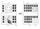
図3は、本実施形態のタッチパネルと連動したハードキーを有する携帯端末装置において、スライド操作による有効部の切り替えを説明するための図である。タッチパネルに指先を接触させ、図3(a)に示すように表示画像(画像領域)25を左右にスライドさせると、図3(b)に示すように有効キー(有効部)31,32及び連動部(有効部連動領域)26,27が切り替わる。また、図3(c)に示すように表示画像25を上下にスライドさせると、図3(d)に示すように有効キー31(32)及び連動部26(27)が切り替わる。同様に、図3(e)に示すように表示画像25を斜めにスライドさせると、図3(f)に示すように有効キー31(32)及び連動部26(27)が切り替わる。 FIG. 3 is a diagram for explaining the switching of the effective part by the slide operation in the mobile terminal device having the hard key interlocked with the touch panel of the present embodiment. When a fingertip is brought into contact with the touch panel and the display image (image area) 25 is slid to the left and right as shown in FIG. 3A, the effective keys (effective portions) 31 and 32 and interlocking as shown in FIG. Parts (effective part interlocking areas) 26 and 27 are switched. When the
すなわち、連動制御部21は、第1の操作部11の画像領域25の移動を検出した場合に、有効部連動領域26,27をずらし、画像領域25および有効部連動領域26,27と位置的に対応するように、有効部31,32および無効部33を切り替える。 That is, when detecting the movement of the
このように本実施形態の携帯端末装置によれば、タッチパネルのタッチキー(有効部連動領域)に対するタッチによる直感的な操作と、テンキーなどとの連携をうまくとり、操作性の向上を図ることができる。すなわち、タッチパネルに対するスライドなどの指による操作で画像を移動させた場合、画像とかぶらないように操作可能なハードキーも(連動させることにより)移動させ、タッチパネルによる直感的な操作性を確保しつつ、テンキーの操作性の向上も図ることができる。 As described above, according to the mobile terminal device of the present embodiment, the intuitive operation by touching the touch key (effective portion interlocking area) of the touch panel and the numeric keypad can be successfully coordinated to improve operability. it can. That is, when an image is moved by an operation with a finger such as a slide on the touch panel, a hard key that can be operated so as not to get hung up with the image is moved (by interlocking) to ensure intuitive operability by the touch panel. Also, the operability of the numeric keypad can be improved.
図4は、本実施形態のタッチパネルと連動したハードキーを有する携帯端末装置において、回転操作(あるいはセンサデバイスでの方向検知)による天頂方向切り替えに伴う有後部切り替えを説明するための図である。 FIG. 4 is a diagram for explaining rear-end switching associated with zenith direction switching by a rotation operation (or direction detection by a sensor device) in a mobile terminal device having a hard key interlocked with the touch panel of the present embodiment.
図4(a)に示す様に、センサ20(図1)が、携帯端末装置、すなわち表示画像(画像領域)55の回転操作を検出することにより、画像および操作部の天頂方向自体を検出し、表示制御部16が、図4(b)に示すように表示画像56およびタッチキー(有効部連動領域)58の天頂方向を切り替える。また、連動制御部21が、ハードキー(物理キー)57をタッチキー58に対応する位置に切り替える。 As shown in FIG. 4A, the sensor 20 (FIG. 1) detects the rotation operation of the mobile terminal device, that is, the display image (image region) 55, thereby detecting the zenith direction itself of the image and the operation unit. Then, the
すなわち、連動制御部21は、第1の操作部11の画像領域55の回転を検出した場合に、画像領域55の天頂方向に対応するように、画像領域55を回転させ、有効部および無効部を切り替える。 That is, when the
このように、タッチキー58およびハードキー57を連動且つ同時操作可能とすることにより、ユーザの持ち方に応じてキー操作に有効な部分を自由に配置でき、操作目的に応じてタッチキー操作やハードキー操作を、フレキシブルに切り替えることができる。 As described above, by enabling the
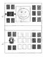
図5は、本実施形態のタッチパネルと連動したハードキーを有する携帯端末装置において、無効部の活用(センサデバイス化)を説明するための図である。本実施形態では、第2の操作部19の入力デバイス62(図1では入力デバイスB17)を多層化することにより、入力デバイス62の上または下にセンサデバイス63が配置されている。そして、表示画像(画像領域)61と連携して無効部64となった領域に対しユーザがタッチした場合、センサデバイス63は当該ユーザの操作を検知し、無効部64を有効化し、ポインタ操作などを可能とする。このように入力デバイス62の上下にセンサデバイス63を配置し、所定の条件に応じて無効部64を有効とすることで、無効部64をも有効に活用することができる。 FIG. 5 is a diagram for explaining the utilization (use of sensor devices) of the invalid portion in the mobile terminal device having the hard keys linked to the touch panel of the present embodiment. In the present embodiment, the sensor device 63 is arranged above or below the input device 62 by multilayering the input device 62 (input device B17 in FIG. 1) of the second operation unit 19. When the user touches the area that has become the invalid portion 64 in cooperation with the display image (image region) 61, the sensor device 63 detects the user's operation, validates the invalid portion 64, and performs a pointer operation or the like. Is possible. Thus, by disposing the sensor devices 63 above and below the input device 62 and enabling the invalid part 64 according to a predetermined condition, the invalid part 64 can also be effectively used.
図6は、本実施形態のタッチパネルと連動したハードキーを有する携帯端末装置において、無効部の活用(無効部押下で画像領域、有効部連動領域を切り替える)を説明するための図である。図6(a)に示すように、画像領域71に隠されたソフトキー部に連動する無効部(物理キー)72は操作無効となっているが、ユーザが無効部72を押下すると、図6(b)に示すように、無効部72に連動する箇所が有効部76になるように、表示画像(画像領域)75が自動で移動する。押下の検知には、図5で説明したセンサデバイス63等を使用することができる。 FIG. 6 is a diagram for explaining the utilization of the invalid part (switching between the image area and the valid part interlocking area when the invalid part is pressed) in the mobile terminal device having a hard key linked to the touch panel of the present embodiment. As shown in FIG. 6A, the invalid portion (physical key) 72 linked to the soft key portion hidden in the
すなわち、連動制御部21は、第2の操作部19の無効部72に対する押下を検出した場合に、無効部72および有効部73を切り替え、無効部77および有効部76と位置的に対応するように、画像領域75および連動部74を移動させる。 That is, when the
本実施形態によれば、無効部72に対する押下を検出した場合に、無効部72および有効部73を切り替え、無効部77および有効部76と位置的に対応するように、画像領域75および操作領域74を移動させるので、画像領域71に対応した無効部72を有効に活用することができる。 According to the present embodiment, when a press on the
図7,8は、本実施形態の携帯端末装置の実現例(ピクチャのサムネイル表示)を説明するための図である。図7は基本画面(横)を示し、図8は基本画面(縦)を示す。状態アイコンまたは機能選択アイコン86により、表示する画像の状態または機能を選択し、前後ページボタン84,85を使用して、フレーム一覧82で表示したい画像を探す。フレーム一覧82において表示したい画像83をフォーカスすると、画像領域81にフォーカスしたフレームの画像が表示される。 7 and 8 are diagrams for explaining an implementation example (picture thumbnail display) of the mobile terminal device of the present embodiment. FIG. 7 shows a basic screen (horizontal), and FIG. 8 shows a basic screen (vertical). The state or function of the image to be displayed is selected by the state icon or the
図9は、本実施形態の携帯端末装置の実現例(ピクチャのサムネイル表示)を説明するための図であり、特に一覧表示(コンテンツ一覧や、動画編集におけるフレーム一覧)を行う場合の操作を示す。この操作では、例えば、(1)左右へのスライド(フリック)でページが移動する。(2)前後ページボタンをタップ(ナビキー左右を長押下でも可)することのよりページが切り替わる。(3)フォーカスするフレーム選択(ナビキー上下左右短押下でも可、テンキー位置に同期)により、フォーカスした画像が画像領域に表示される。タッチパネルの有効部連動領域は、入力デバイスの有効部の同位置のものとリンクする。 FIG. 9 is a diagram for explaining an implementation example (picture thumbnail display) of the mobile terminal device of the present embodiment, and particularly shows an operation in the case of performing a list display (a content list or a frame list in moving image editing). . In this operation, for example, (1) the page is moved by sliding (flicking) left and right. (2) The pages are switched by tapping the front / rear page buttons (or long pressing the navigation key left / right). (3) The focused image is displayed in the image area by selecting the frame to be focused (the navigation key can be pressed up and down, left and right, or synchronized with the numeric keypad position). The effective part interlocking area of the touch panel is linked to the same position of the effective part of the input device.
図10は、本実施形態の携帯端末装置の実現例(ピクチャのサムネイル表示)を説明するための図であり、特に選択フレームの編集画面への遷移を示す。図10(a)に示すように、(4)フォーカス画像を右へスライド(S1キー長押下でも可)することにより、図10(b)に示すように、スライドさせた画像の下から、ナビキーにリンクした編集画面機能キー101が現れる。 FIG. 10 is a diagram for explaining an implementation example (picture thumbnail display) of the mobile terminal device of the present embodiment, and particularly shows the transition of the selected frame to the edit screen. As shown in FIG. 10 (a), (4) By sliding the focus image to the right (the S1 key length can be pressed), as shown in FIG. 10 (b), from the bottom of the slid image, the navigation key The edit
図11は、本実施形態の携帯端末装置の実現例(ピクチャのサムネイル表示)を説明するための図であり、特に選択フレームの編集画面を示す。図11(a)に示すように、(1)機能の選択はスクロールキーに連動し、同位置のものとリンクする。(2)上左は前の画像、下右は次の画像、キーの上下左右にも連動する。また、図11(b)に画像のスクロール順を示す。 FIG. 11 is a diagram for explaining an implementation example (picture thumbnail display) of the mobile terminal device of the present embodiment, and particularly shows an edit screen for a selected frame. As shown in FIG. 11 (a), (1) function selection is linked to a scroll key and linked to the same position. (2) The upper left is the previous image, the lower right is the next image, and the top, bottom, left and right of the key are also linked. FIG. 11B shows the scrolling order of the images.
図12,13は、本実施形態の携帯端末装置のタッチパネルと連動したハードキーを有する携帯端末装置における回転型セレクタを示す。図12において、セレクタ連動部111は、回転型セレクタ112の回転に連動し、押し込み連動またはタッチで決定する。回転型セレクタ112は、回して選択、押し込みで決定する。また、図13において、セレクタ連動部115は、回転型セレクタ116の回転に連動し、押し込み連動またはタッチで決定する。回転型セレクタ116は、回して選択、押し込みで決定する。 12 and 13 show a rotary selector in a mobile terminal device having a hard key interlocked with the touch panel of the mobile terminal device of the present embodiment. In FIG. 12, the
本実施形態によれば、連動制御部21は、セレクタ連動部111,115が回転型セレクタ112,116に位置的に対応している場合に、回転型セレクタ112,116に対する操作を有効にするので、表示画像を見ながら回転型セレクタ112,116の操作を容易に行うことができる。 According to the present embodiment, the
以上説明したように、本実施の形態にかかる携帯端末装置は、少なくとも2種類の操作部を備え、当該2種類の操作部が連動しているということを、ユーザに対し直感的に理解させることができる。したがって、携帯端末装置の操作性の向上を図ることができる。 As described above, the mobile terminal device according to the present embodiment includes at least two types of operation units, and allows the user to intuitively understand that the two types of operation units are linked. Can do. Therefore, the operability of the mobile terminal device can be improved.
また、2種類の操作部は、表示配置を工夫することにより連動していることを直感的に理解させる。そのため、例えばタッチパネル側のある位置に表示される内容は、その画面の用途により変更することが可能である。したがって、ある位置に表示される操作部はその画面状態に応じたものにフレキシブルに変更することが可能となり、携帯端末装置の操作性の向上を図ることができる。また、携帯端末装置の表現力の向上を図ることもできる。 In addition, the two types of operation units intuitively understand that they are linked by devising the display arrangement. Therefore, for example, the content displayed at a certain position on the touch panel side can be changed according to the use of the screen. Therefore, the operation unit displayed at a certain position can be flexibly changed to one corresponding to the screen state, and the operability of the mobile terminal device can be improved. In addition, the expressive power of the mobile terminal device can be improved.
本発明によれば、携帯端末装置において、2種類の操作部が連動しているということを、ユーザに対し直感的に理解させることができる。したがって、例えば、一方の操作部が大雑把な選択を担い、他方の操作部が微調整を担うといったような、互いに性質の異なる二つの操作部の連動性の把握容易性を高めることができる。 ADVANTAGE OF THE INVENTION According to this invention, in a portable terminal device, it can make a user intuitively understand that two types of operation parts are interlock | cooperating. Therefore, for example, it is possible to improve the ease of grasping the interlocking properties of two operation units having different properties such that one operation unit is responsible for rough selection and the other operation unit is responsible for fine adjustment.
なお、本発明は上記の実施形態において示されたものに限定されるものではなく、明細書の記載、並びに周知の技術に基づいて、当業者が変更、応用することも本発明の予定するところであり、保護を求める範囲に含まれる。 It should be noted that the present invention is not limited to those shown in the above-described embodiments, and those skilled in the art can also make changes and applications based on the description in the specification and well-known techniques. Yes, included in the scope of protection.
本発明は、2種類の操作部が直感的に連動しているということが分かるような画面表示を行い、2種類の操作部(例えばタッチパネルと物理キーなど)を連携させる携帯端末装置を提供する。 The present invention provides a mobile terminal device that displays a screen so that it can be understood that two types of operation units are intuitively linked, and links two types of operation units (for example, a touch panel and a physical key). .
1 操作部
2 表示部
3 マイク
4 レシーバ
5 アンテナ
6 操作部表示
7 開始キー
8 表示画面
9 電源スイッチソフトキー
10 ソフトキー群
11 第1の操作部
12 タッチパネル
13 入力デバイスA
14 ディスプレイ
15 入力制御部
16 表示制御部
17 入力デバイスB
18,57 物理キー(ハードキー)
19 第2の操作部
20 センサ
21 連動制御部
22 バックライト
25 画像領域(表示画像)
26,27,74 有効部連動領域(連動部)
28 タッチパネル
29 ヒンジ
31,32,73,76 有効部
33,64,72,77 無効部
55,56,61,71,75,81 画像領域(表示画像)
58 ソフトキー(タッチキー)
63 センサデバイス
82 フレーム一覧
83 画像
84,85 前後ページボタン
101 編集画面機能キー
111,115 セレクタ連動部
112,116 回転型セレクタDESCRIPTION OF SYMBOLS 1 Operation part 2
14
18, 57 Physical key (hard key)
19
26, 27, 74 Effective part interlocking area (interlocking part)
28 Touch panel 29
58 soft keys (touch keys)
63
Claims (11)
Translated fromJapanese前記第1の操作部の前記操作領域と連動する第2の操作部と、
を備える携帯端末装置。A first operation unit having an image area for displaying an image and an operation area for displaying an operation key;
A second operation unit interlocking with the operation area of the first operation unit;
A mobile terminal device comprising:
前記第2の操作部は、前記第1の操作部の前記操作領域に対応する部分の入力を有効にし、前記第1の操作部の前記画像領域に対応する部分の入力を無効にする、携帯端末装置。The mobile terminal device according to claim 1,
The second operation unit enables input of a portion corresponding to the operation region of the first operation unit, and disables input of a portion corresponding to the image region of the first operation unit. Terminal device.
前記第2の操作部は、前記第1の操作部の前記操作領域に対応する部分のバックライトを点灯し、前記第1の操作部の前記画像領域に対応する部分のバックライトを点灯しない、携帯端末装置。The portable terminal device according to claim 1 or 2, wherein
The second operation unit turns on a backlight of a portion corresponding to the operation region of the first operation unit, and does not turn on a backlight of a portion corresponding to the image region of the first operation unit; Mobile terminal device.
前記第2の操作部は、前記第1の操作部の前記画像領域に対応する部分でポインタ操作を受け付ける、携帯端末装置。The mobile terminal device according to claim 1,
The second operation unit is a portable terminal device that accepts a pointer operation at a portion corresponding to the image area of the first operation unit.
前記第1の操作部はタッチパネルより構成され、
前記第2の操作部は、ハードキーより構成される、携帯端末装置。It is a portable terminal device given in any 1 paragraph of Claims 1-4,
The first operation unit includes a touch panel,
The second operation unit is a mobile terminal device configured by hard keys.
前記第1および第2の操作部から受信したデータを、前記第1の操作部に現在表示されている状態と対比させ有効/無効の判定を行う連動制御部を備える、携帯端末装置。The mobile terminal device according to claim 1,
A portable terminal device comprising: an interlocking control unit that determines validity / invalidity by comparing data received from the first and second operation units with a state currently displayed on the first operation unit.
前記連動制御部は、前記第2の操作部において、前記第1の操作部の前記操作領域と位置的に対応する部分を有効部とし、前記第1の操作部の前記画像領域と位置的に対応する部分を無効部とする、携帯端末装置。The mobile terminal device according to claim 6,
In the second operation unit, the interlock control unit uses a portion corresponding to the operation region of the first operation unit as an effective unit, and is positioned relative to the image region of the first operation unit. A mobile terminal device in which a corresponding part is an invalid part.
前記連動制御部は、前記第1の操作部の前記画像領域の移動を検出した場合に、前記操作領域をずらし、前記画像領域および前記操作領域と位置的に対応するように、前記有効部および前記無効部を切り替える、携帯端末装置。The mobile terminal device according to claim 7,
When the movement control unit detects the movement of the image region of the first operation unit, the interlock control unit shifts the operation region so as to correspond to the image region and the operation region in position. A portable terminal device that switches the invalid portion.
前記連動制御部は、前記第1の操作部の前記画像領域の回転を検出した場合に、前記画像領域の天頂方向に対応するように、前記操作領域を回転させ、前記有効部および前記無効部を切り替える、携帯端末装置。The mobile terminal device according to claim 7,
The interlock control unit rotates the operation region so as to correspond to a zenith direction of the image region when detecting the rotation of the image region of the first operation unit, and the effective unit and the invalid unit. Switch the mobile terminal device.
前記連動制御部は、前記第2の操作部の前記無効部に対する押下を検出した場合に、前記無効部および前記有効部を切り替え、前記無効部および前記有効部と位置的に対応するように、前記画像領域および前記操作領域を移動させる、携帯端末装置。The mobile terminal device according to claim 7,
When the interlock control unit detects pressing of the second operation unit with respect to the invalid part, the invalid part and the valid part are switched, and the invalid part and the valid part correspond to each other in position. A mobile terminal device that moves the image area and the operation area.
前記第2の操作部は、回転型セレクタを含み、
前記連動制御部は、前記第1の操作部の前記操作領域が前記回転型セレクタに位置的に対応している場合に、前記回転型セレクタに対する操作を有効にする、携帯端末装置。The mobile terminal device according to claim 6,
The second operation unit includes a rotary selector,
The interlock control unit is a portable terminal device that enables an operation on the rotary selector when the operation area of the first operation unit corresponds to the rotary selector in position.
Priority Applications (4)
| Application Number | Priority Date | Filing Date | Title |
|---|---|---|---|
| JP2009133135AJP2010283442A (en) | 2009-06-02 | 2009-06-02 | Mobile terminal device |
| PCT/JP2010/001157WO2010140282A1 (en) | 2009-06-02 | 2010-02-22 | Portable terminal apparatus |
| BRPI1011863ABRPI1011863A2 (en) | 2009-06-02 | 2010-02-22 | portable terminal handset |
| US13/322,415US20120071212A1 (en) | 2009-06-02 | 2010-02-22 | Portable terminal apparatus |
Applications Claiming Priority (1)
| Application Number | Priority Date | Filing Date | Title |
|---|---|---|---|
| JP2009133135AJP2010283442A (en) | 2009-06-02 | 2009-06-02 | Mobile terminal device |
Publications (1)
| Publication Number | Publication Date |
|---|---|
| JP2010283442Atrue JP2010283442A (en) | 2010-12-16 |
Family
ID=43297425
Family Applications (1)
| Application Number | Title | Priority Date | Filing Date |
|---|---|---|---|
| JP2009133135AWithdrawnJP2010283442A (en) | 2009-06-02 | 2009-06-02 | Mobile terminal device |
Country Status (4)
| Country | Link |
|---|---|
| US (1) | US20120071212A1 (en) |
| JP (1) | JP2010283442A (en) |
| BR (1) | BRPI1011863A2 (en) |
| WO (1) | WO2010140282A1 (en) |
Cited By (6)
| Publication number | Priority date | Publication date | Assignee | Title |
|---|---|---|---|---|
| JP2014063222A (en)* | 2012-09-19 | 2014-04-10 | Sharp Corp | Communication terminal device, setting method, program, and recording medium |
| JP2014069365A (en)* | 2012-09-28 | 2014-04-21 | Brother Ind Ltd | Printer |
| KR20140061587A (en)* | 2012-11-12 | 2014-05-22 | 엘지전자 주식회사 | A mobile terminal and a mobile terminal control method |
| JPWO2013024530A1 (en)* | 2011-08-15 | 2015-03-05 | 富士通株式会社 | Portable electronic device and key display program |
| CN104932799A (en)* | 2014-03-19 | 2015-09-23 | 联想(北京)有限公司 | Information processing method and electronic equipment |
| JP2015168268A (en)* | 2014-03-04 | 2015-09-28 | 株式会社デンソー | Vehicular operation device |
Families Citing this family (9)
| Publication number | Priority date | Publication date | Assignee | Title |
|---|---|---|---|---|
| JP5717601B2 (en)* | 2011-09-30 | 2015-05-13 | アルパイン株式会社 | Operation control device and operation control method for external device connected to in-vehicle device |
| KR101936090B1 (en)* | 2012-08-29 | 2019-01-08 | 삼성전자주식회사 | Apparatus for controlling key input and method for the same |
| US20150339028A1 (en)* | 2012-12-28 | 2015-11-26 | Nokia Technologies Oy | Responding to User Input Gestures |
| US20140267051A1 (en)* | 2013-03-14 | 2014-09-18 | Garmin International, Inc. | Hybrid aviation user interface |
| JP2015007949A (en) | 2013-06-26 | 2015-01-15 | ソニー株式会社 | Display device, display controlling method, and computer program |
| US9420445B2 (en)* | 2014-01-08 | 2016-08-16 | Cisco Technology, Inc. | Universal code for emergency calls mode in a network environment |
| USD752615S1 (en)* | 2014-04-17 | 2016-03-29 | Huawei Device Co., Ltd. | Display screen or portion thereof with a graphical user interface |
| CN105472111A (en)* | 2014-09-03 | 2016-04-06 | 中兴通讯股份有限公司 | Touch screen terminal key function switching method and apparatus |
| JP6293209B2 (en)* | 2016-07-14 | 2018-03-14 | レノボ・シンガポール・プライベート・リミテッド | Information processing apparatus, erroneous operation suppression method, and program |
Family Cites Families (8)
| Publication number | Priority date | Publication date | Assignee | Title |
|---|---|---|---|---|
| JP2002101168A (en)* | 2000-09-26 | 2002-04-05 | Matsushita Electric Ind Co Ltd | Foldable portable wireless device |
| JP4036823B2 (en)* | 2003-12-10 | 2008-01-23 | シャープ株式会社 | Remote control device |
| TWI265447B (en)* | 2005-06-06 | 2006-11-01 | Asustek Comp Inc | Electronic device with an auxiliary display apparatus |
| JP4657116B2 (en)* | 2006-02-06 | 2011-03-23 | アルパイン株式会社 | Display device, menu providing device, and menu providing method |
| KR20070082691A (en)* | 2006-02-17 | 2007-08-22 | 삼성전자주식회사 | Digital multimedia devices |
| JP2008003242A (en)* | 2006-06-21 | 2008-01-10 | Sharp Corp | Display panel holding member and display device |
| JP4179367B2 (en)* | 2006-09-05 | 2008-11-12 | ソニー株式会社 | Information processing system, information processing apparatus, information processing method, program, and recording medium |
| US8185170B2 (en)* | 2008-03-28 | 2012-05-22 | Kyocera Corporation | Portable electronic apparatus |
- 2009
- 2009-06-02JPJP2009133135Apatent/JP2010283442A/ennot_activeWithdrawn
- 2010
- 2010-02-22USUS13/322,415patent/US20120071212A1/ennot_activeAbandoned
- 2010-02-22WOPCT/JP2010/001157patent/WO2010140282A1/enactiveApplication Filing
- 2010-02-22BRBRPI1011863Apatent/BRPI1011863A2/ennot_activeApplication Discontinuation
Cited By (7)
| Publication number | Priority date | Publication date | Assignee | Title |
|---|---|---|---|---|
| JPWO2013024530A1 (en)* | 2011-08-15 | 2015-03-05 | 富士通株式会社 | Portable electronic device and key display program |
| JP2014063222A (en)* | 2012-09-19 | 2014-04-10 | Sharp Corp | Communication terminal device, setting method, program, and recording medium |
| JP2014069365A (en)* | 2012-09-28 | 2014-04-21 | Brother Ind Ltd | Printer |
| KR20140061587A (en)* | 2012-11-12 | 2014-05-22 | 엘지전자 주식회사 | A mobile terminal and a mobile terminal control method |
| KR101984588B1 (en)* | 2012-11-12 | 2019-05-31 | 엘지전자 주식회사 | Mobile terminal and method for controlling mobile terminal |
| JP2015168268A (en)* | 2014-03-04 | 2015-09-28 | 株式会社デンソー | Vehicular operation device |
| CN104932799A (en)* | 2014-03-19 | 2015-09-23 | 联想(北京)有限公司 | Information processing method and electronic equipment |
Also Published As
| Publication number | Publication date |
|---|---|
| WO2010140282A1 (en) | 2010-12-09 |
| BRPI1011863A2 (en) | 2016-03-29 |
| US20120071212A1 (en) | 2012-03-22 |
Similar Documents
| Publication | Publication Date | Title |
|---|---|---|
| JP2010283442A (en) | Mobile terminal device | |
| JP4364273B2 (en) | Portable terminal device, display control method, and display control program | |
| JP5215502B2 (en) | Input device | |
| JP5323603B2 (en) | Image display device | |
| JP5749043B2 (en) | Electronics | |
| US9626093B2 (en) | Display apparatus, information input method and program | |
| JP2007179502A (en) | Information processing device | |
| JP2012231274A (en) | Portable terminal device and program | |
| CN101414229A (en) | Control method and device for executing switching function of touch screen of handheld electronic device | |
| KR20110063570A (en) | Display method in electronic equipment and electronic equipment | |
| JP2010062849A (en) | Portable terminal apparatus, and input operation method and display control method of portable terminal apparatus | |
| JP5037571B2 (en) | Portable terminal device, display control method, and display control program | |
| JP5025450B2 (en) | Character input device | |
| JP2011203808A (en) | Mobile information terminal | |
| JP5926968B2 (en) | Display device, display method, and program | |
| US20150123916A1 (en) | Portable terminal device, method for operating portable terminal device, and program for operating portable terminal device | |
| JP5252751B2 (en) | Mobile terminal device | |
| JP5670137B2 (en) | Portable electronic device and display control method for portable electronic device | |
| JP2009099057A (en) | Mobile terminal device and character input method | |
| JP2015007856A (en) | INPUT DEVICE, IMAGE READING DEVICE, IMAGE FORMING DEVICE, INPUT METHOD, AND PROGRAM | |
| JP6027182B2 (en) | Electronics | |
| JP6367720B2 (en) | Information processing apparatus and program | |
| JP2014021528A (en) | Information processing device, display control method, and program | |
| JP5042385B2 (en) | Portable terminal device, display control method, and display control program | |
| KR100861449B1 (en) | Screen scroll control system and method for mobile communication terminal |
Legal Events
| Date | Code | Title | Description |
|---|---|---|---|
| A621 | Written request for application examination | Free format text:JAPANESE INTERMEDIATE CODE: A621 Effective date:20120508 | |
| A761 | Written withdrawal of application | Free format text:JAPANESE INTERMEDIATE CODE: A761 Effective date:20130801 |