JP2010271565A - Head-mounted display device - Google Patents
Head-mounted display deviceDownload PDFInfo
- Publication number
- JP2010271565A JP2010271565AJP2009123873AJP2009123873AJP2010271565AJP 2010271565 AJP2010271565 AJP 2010271565AJP 2009123873 AJP2009123873 AJP 2009123873AJP 2009123873 AJP2009123873 AJP 2009123873AJP 2010271565 AJP2010271565 AJP 2010271565A
- Authority
- JP
- Japan
- Prior art keywords
- light
- optical system
- observer
- image
- eye
- Prior art date
- Legal status (The legal status is an assumption and is not a legal conclusion. Google has not performed a legal analysis and makes no representation as to the accuracy of the status listed.)
- Withdrawn
Links
- 230000003287optical effectEffects0.000claimsabstractdescription192
- 210000003128headAnatomy0.000claimsabstractdescription4
- 208000003464asthenopiaDiseases0.000abstractdescription14
- 230000004907fluxEffects0.000description23
- 238000010586diagramMethods0.000description14
- 230000008859changeEffects0.000description8
- 239000006185dispersionSubstances0.000description6
- 230000005540biological transmissionEffects0.000description5
- 238000005286illuminationMethods0.000description4
- 239000003086colorantSubstances0.000description3
- 238000005401electroluminescenceMethods0.000description3
- 238000000034methodMethods0.000description3
- 230000000007visual effectEffects0.000description3
- 239000004925Acrylic resinSubstances0.000description2
- 229920000178Acrylic resinPolymers0.000description2
- 230000004075alterationEffects0.000description2
- XAGFODPZIPBFFR-UHFFFAOYSA-NaluminiumChemical compound[Al]XAGFODPZIPBFFR-UHFFFAOYSA-N0.000description2
- 229910052782aluminiumInorganic materials0.000description2
- 238000005452bendingMethods0.000description2
- 239000004973liquid crystal related substanceSubstances0.000description2
- 239000011295pitchSubstances0.000description2
- OAICVXFJPJFONN-UHFFFAOYSA-NPhosphorusChemical compound[P]OAICVXFJPJFONN-UHFFFAOYSA-N0.000description1
- 101100347655Saccharomyces cerevisiae (strain ATCC 204508 / S288c) NAB3 geneProteins0.000description1
- 230000003321amplificationEffects0.000description1
- 230000007423decreaseEffects0.000description1
- 238000009792diffusion processMethods0.000description1
- 230000000694effectsEffects0.000description1
- 238000005516engineering processMethods0.000description1
- 208000013057hereditary mucoepithelial dysplasiaDiseases0.000description1
- 238000010030laminatingMethods0.000description1
- 230000007246mechanismEffects0.000description1
- 238000003199nucleic acid amplification methodMethods0.000description1
- 229920005668polycarbonate resinPolymers0.000description1
- 239000004431polycarbonate resinSubstances0.000description1
- 229920005990polystyrene resinPolymers0.000description1
- 210000001747pupilAnatomy0.000description1
- 239000011347resinSubstances0.000description1
- 229920005989resinPolymers0.000description1
Images


Landscapes
- Diffracting Gratings Or Hologram Optical Elements (AREA)
Abstract
Description
Translated fromJapanese本発明は、頭部装着型表示装置に関するものである。 The present invention relates to a head-mounted display device.
近年、ヘッドマウントディスプレイ(頭部装着型表示装置、Head Mounted Display;HMD)が普及している。一般に、HMDとしては左右一対の画像表示装置に表示された画像を観察者に両眼で観察させる両眼式のHMDが採用されている(例えば、特許文献1参照)。このような両眼式のHMDを観察者が装着した場合、観察者は左右のそれぞれの表示画像を重ねて1つの画像として観察する。 In recent years, head-mounted displays (head-mounted display devices, head mounted displays; HMDs) have become widespread. In general, as the HMD, a binocular HMD that allows an observer to observe an image displayed on a pair of left and right image display devices with both eyes is employed (see, for example, Patent Document 1). When an observer wears such a binocular HMD, the observer superimposes the left and right display images and observes them as one image.
人の眼は、輻輳角が変化することにより視認距離を知覚する。つまり、観察者が近くのものを見る場合には輻輳角は大きくなり、遠くのものを見る場合には輻輳角は小さくなる。このような特性により、観察者は視対象との距離感を感じている。そこで、観察者が左右のそれぞれの表示画像を重ねて1つの画像として観察する際に眼が疲れないように輻輳角(観察者の両眼の視線が視対象の位置に収束してできる角度)を調整できる技術が求められている。 The human eye perceives the viewing distance as the angle of convergence changes. That is, the convergence angle increases when the observer looks at a nearby object, and the convergence angle decreases when the observer looks at a distant object. Due to such characteristics, the observer feels a sense of distance from the visual target. Therefore, the angle of convergence so that the eyes do not get tired when the observer superimposes the left and right display images as a single image (the angle at which the eyes of the observer's eyes converge to the position of the visual target). There is a need for technology that can adjust
図6は、特許文献1における両眼式のHMDにおいて表示画像に対する観察者の両眼の視線を示した模式図である。図6に示すように、左右一対の画像表示装置に表示された表示画像1010を観察者の両眼1050のそれぞれに対応する位置に配置することにより、観察者は左右のそれぞれの表示画像1010を重ねて1つの画像として観察する。輻輳角を調整するために図7の構成も考えられるが、左右一対の画像表示装置を傾けるとすると、表示画像1010が画像表示装置の傾きに倣って観察者の左右の眼1050のそれぞれに対応して傾くことになる。このような位置関係は、例えば日常生活における観察者のディスプレイの視聴状態とは異なるものとなる。つまり、日常ありえない表示画像1010に対する観察者の左右の眼1050の位置関係となり、観察者に違和感を与え、眼精疲労の原因にもなりかねない。 FIG. 6 is a schematic diagram showing the eyes of the observer's eyes with respect to the display image in the binocular HMD in Patent Document 1. As shown in FIG. 6, by arranging
一方、特許文献1の技術にあっては、左右一対の光軸のなす角を調整する光軸調整手段を設けることにより、左右のそれぞれにおいて光軸調整を行い、観察者が左右のそれぞれの表示画像を重ねて1つの画像として観察することができる技術が開示されているが、輻輳角を調整する技術については全く記載されていない。 On the other hand, in the technique of Patent Document 1, by providing an optical axis adjusting means for adjusting an angle formed by a pair of left and right optical axes, the optical axis is adjusted in each of the left and right, and the observer displays each of the left and right displays. Although a technique capable of observing a single image by superimposing images is disclosed, a technique for adjusting the convergence angle is not described at all.
本発明はこのような事情に鑑みてなされたものであって、自然な輻輳角をもたせることにより観察者の眼精疲労を軽減することが可能な頭部装着型表示装置を提供することを目的とする。 The present invention has been made in view of such circumstances, and an object of the present invention is to provide a head-mounted display device that can reduce eye strain of an observer by providing a natural angle of convergence. And
上記の課題を解決するため、本発明の頭部装着型表示装置は、観察者の頭部に装着されて画像表示を行う頭部装着型表示装置であって、前記観察者の右眼に対応した表示画像光を出射する右眼用の画像表示光学系と、前記観察者の左眼に対応した表示画像光を出射する左眼用の画像表示光学系と、前記右眼用の画像表示光学系と前記左眼用の画像表示光学系とを前記観察者の右眼と左眼とを結ぶ線に平行に相対移動させることにより、前記観察者の両眼の輻輳角を所定の値に調整する輻輳角調整手段と、を備えることを特徴とする In order to solve the above-described problem, the head-mounted display device of the present invention is a head-mounted display device that displays an image by being mounted on the observer's head, and corresponds to the right eye of the observer. An image display optical system for the right eye that emits the displayed image light, an image display optical system for the left eye that emits display image light corresponding to the left eye of the observer, and an image display optical for the right eye The vergence angle of both eyes of the observer is adjusted to a predetermined value by relatively moving the system and the image display optical system for the left eye in parallel with a line connecting the right eye and the left eye of the observer And a convergence angle adjusting means for performing
この構成によれば、右眼用の画像表示光学系と左眼用の画像表示光学系とを観察者の右眼と左眼とを結ぶ線に平行に相対移動させることにより、観察者の両眼の輻輳角を所定の値に調整する輻輳角調整手段が設けられている。つまり、観察者は輻輳角調整手段を用いて所望の輻輳角となるように各画像表示光学系の位置を適宜変更できる。したがって、自然な輻輳角をもたせることにより観察者の眼精疲労を軽減することが可能となる。 According to this configuration, the image display optical system for the right eye and the image display optical system for the left eye are moved relative to each other in parallel to the line connecting the right eye and the left eye of the observer. Convergence angle adjusting means for adjusting the convergence angle of the eye to a predetermined value is provided. That is, the observer can appropriately change the position of each image display optical system so as to obtain a desired convergence angle using the convergence angle adjusting means. Therefore, it is possible to reduce the eye strain of the observer by giving a natural angle of convergence.
また、上記頭部装着型表示装置においては、前記右眼用の画像表示光学系と前記左眼用の画像表示光学系とのそれぞれにおいて、前記各画像表示光学系は、光を出射する光源と、前記光源からの光を変調して前記画像表示を行う画像表示素子と、を含む第1光学系と、前記第1光学系から出射された表示画像光を内部全反射して導光する導光板と、前記導光板に前記第1光学系から入射された前記表示画像光を、前記導光板の内部全反射条件を満たすように回折または反射する第1光路変更手段と、前記第1光路変更手段から出射され前記導光板で内部全反射して導光される前記表示画像光を、前記導光板の前記内部全反射条件から外れるように回折または反射して、前記導光板から前記観察者の眼に向けて出射させる第2光路変更手段と、を含む第2光学系と、を有し、前記輻輳角調整手段は、前記右眼用の画像表示光学系に含まれる右眼用の第1光学系と、前記左眼用の画像表示光学系に含まれる左眼用の第1光学系と、を前記観察者の右眼と左眼とを結ぶ線に平行に相対移動させることにより、前記観察者の両眼の輻輳角を所定の値に調整していてもよい。 In the head-mounted display device, in each of the image display optical system for the right eye and the image display optical system for the left eye, each of the image display optical systems includes a light source that emits light. A first optical system including an image display element that modulates light from the light source and displays the image, and a guide that guides display image light emitted from the first optical system by total internal reflection. An optical plate, first optical path changing means for diffracting or reflecting the display image light incident on the light guide plate from the first optical system so as to satisfy an internal total reflection condition of the light guide plate, and the first optical path change The display image light emitted from the means and guided by being totally internally reflected by the light guide plate is diffracted or reflected so as to deviate from the internal total reflection condition of the light guide plate, and is then reflected from the light guide plate to the observer. Second optical path changing means for emitting toward the eye; And the convergence angle adjusting means includes a first optical system for the right eye included in the image display optical system for the right eye, and an image display optical system for the left eye. The convergence angle of both eyes of the observer is adjusted to a predetermined value by relatively moving the first optical system for the left eye included in parallel with a line connecting the right eye and the left eye of the observer. You may do it.
この構成によれば、右眼用の第1光学系と左眼用の第1光学系とを観察者の右眼と左眼とを結ぶ線に平行に相対移動させることにより、観察者の両眼の輻輳角を所定の値に調整する輻輳角調整手段が設けられている。つまり、観察者は輻輳角調整手段を用いて所望の輻輳角となるように各第1光学系の位置を適宜変更できる。したがって、自然な輻輳角をもたせることにより観察者の眼精疲労を軽減することが可能となる。 According to this configuration, the first optical system for the right eye and the first optical system for the left eye are moved relative to each other in parallel to the line connecting the right eye and the left eye of the observer. Convergence angle adjusting means for adjusting the convergence angle of the eye to a predetermined value is provided. That is, the observer can appropriately change the position of each first optical system using the convergence angle adjusting means so as to obtain a desired convergence angle. Therefore, it is possible to reduce the eye strain of the observer by giving a natural angle of convergence.
また、上記頭部装着型表示装置においては、前記所定の値が1.14〜2.56°の範囲内となっていることが望ましい。 In the head-mounted display device, it is desirable that the predetermined value is within a range of 1.14 to 2.56 °.
この構成によれば、一般的な仮想画面に対する視認距離の条件において自然な輻輳角となるため、観察者の眼精疲労が軽減される。これは、人間の眼の幅が通常の範囲内(例えば4〜9cm)にある場合、例えばHMDの仕様として仮想画面に対する視認距離が2mに設定されているとすると、観察者の両眼の輻輳角が1.14〜2.56°の範囲内に設定されることで自然な輻輳角が得られることによる。 According to this configuration, since the angle of convergence is natural under the condition of the viewing distance with respect to a general virtual screen, the eye strain of the observer is reduced. This is because when the human eye width is within a normal range (for example, 4 to 9 cm), for example, if the viewing distance to the virtual screen is set to 2 m as the HMD specifications, the congestion of the eyes of the observer This is because a natural convergence angle can be obtained by setting the angle within a range of 1.14 to 2.56 °.
また、上記頭部装着型表示装置においては、前記右眼用の画像表示光学系に含まれる右眼用の第2光学系と前記左眼用の画像表示光学系に含まれる左眼用の第2光学系とのそれぞれにおいて、前記各第1光路変更手段は、前記表示画像光を回折する第1ホログラム素子を有し、前記各第2光路変更手段は、前記第1ホログラム素子から出射され前記導光板内部で全反射して導光される前記表示画像光を前記観察者の眼に向けて回折する第2ホログラム素子を有していてもよい。 In the head-mounted display device, the second optical system for the right eye included in the image display optical system for the right eye and the first for the left eye included in the image display optical system for the left eye. In each of the two optical systems, each of the first optical path changing means includes a first hologram element that diffracts the display image light, and each of the second optical path changing means is emitted from the first hologram element and You may have the 2nd hologram element which diffracts the said display image light guided by the total reflection inside a light-guide plate toward the said observer's eyes.
この構成によれば、右眼用の第2光学系と左眼用の第2光学系とのそれぞれにおいて、各第1光路変更手段として表示画像光を回折する第1ホログラム素子を用いているため、一般的な反射板を用いるよりも各第1光路変更手段に対する画像表示光の反射角度を大きくすることができる。第1光路変更手段に対する画像表示光の反射角度を大きくすることで、左右一対の表示画像の位置を変更しやすくなる。例えば、輻輳角調整手段による調整範囲(例えば第1光学系の移動可能な範囲)が小さい場合であっても、第1光路変更手段としてホログラム素子を用いることで左右一対の表示画像の位置を変更して、観察者の両眼の輻輳角を所定の値に調整できる。したがって、輻輳角調整手段による調整範囲が小さくても、自然な輻輳角をもたせることにより観察者の眼精疲労を軽減することが可能となる。 According to this configuration, each of the second optical system for the right eye and the second optical system for the left eye uses the first hologram element that diffracts the display image light as each first optical path changing unit. The angle of reflection of the image display light with respect to each first optical path changing means can be made larger than using a general reflector. By increasing the reflection angle of the image display light with respect to the first optical path changing means, the positions of the left and right display images can be easily changed. For example, even if the adjustment range by the convergence angle adjustment means (for example, the movable range of the first optical system) is small, the position of the pair of left and right display images is changed by using the hologram element as the first optical path changing means. Thus, the vergence angle of both eyes of the observer can be adjusted to a predetermined value. Therefore, even if the adjustment range by the convergence angle adjusting means is small, it is possible to reduce the eye strain of the observer by providing a natural convergence angle.
また、上記頭部装着型表示装置においては、前記第1ホログラム素子及び前記第2ホログラム素子は、赤色光の波長域の表示画像光を選択的に回折する赤色光用ホログラム層と、緑色光の波長域の表示画像光を選択的に回折する緑色光用ホログラム層と、青色光の波長域の表示画像光を選択的に回折する青色光用ホログラム層と、を有し、前記赤色光用ホログラム層、前記緑色光用ホログラム層、前記青色光用ホログラム層は、同一の入射角で入射される互いに異なる波長域の前記表示画像光を、それぞれ略同一の回折角にて回折してもよい。 In the head-mounted display device, the first hologram element and the second hologram element include a red light hologram layer that selectively diffracts display image light in a wavelength range of red light, and green light. A hologram layer for green light that selectively diffracts display image light in a wavelength region and a hologram layer for blue light that selectively diffracts display image light in a wavelength region of blue light, the hologram for red light The layer, the green light hologram layer, and the blue light hologram layer may each diffract the display image light having different wavelength ranges incident at the same incident angle at substantially the same diffraction angle.
この構成によれば、赤色光用ホログラム層によって赤色光が選択的に回折され、青色光用ホログラム層によって青色光が選択的に回折され、緑色光用ホログラム層によって緑色光が選択的に回折される。そして、各色光用ホログラム層は、同一の入射角で入射される互いに異なる波長域の表示画像光を、それぞれ略同一の回折角で回折する。このため、カラー化した場合には、各色光用のホログラム層を設けることによって各色光の回折角(導光板内部の全反射角)をほぼ等しくすることができる。したがって、カラー化した場合において、自然な輻輳角をもたせることにより観察者の眼精疲労を軽減することが可能となる。 According to this configuration, red light is selectively diffracted by the red light hologram layer, blue light is selectively diffracted by the blue light hologram layer, and green light is selectively diffracted by the green light hologram layer. The Each color light hologram layer diffracts display image light having different wavelength ranges incident at the same incident angle at substantially the same diffraction angle. For this reason, in the case of colorization, the diffraction angle of each color light (total reflection angle inside the light guide plate) can be made substantially equal by providing a hologram layer for each color light. Therefore, in the case of colorization, it is possible to reduce the eye strain of the observer by giving a natural convergence angle.
以下、図面を参照して、本発明の実施の形態について説明する。かかる実施の形態は、本発明の一態様を示すものであり、この発明を限定するものではなく、本発明の技術的思想の範囲内で任意に変更可能である。また、以下の図面においては、各構成をわかりやすくするために、実際の構造と各構造における縮尺や数等が異なっている。 Embodiments of the present invention will be described below with reference to the drawings. This embodiment shows one aspect of the present invention, and does not limit the present invention, and can be arbitrarily changed within the scope of the technical idea of the present invention. Moreover, in the following drawings, in order to make each structure easy to understand, an actual structure and a scale, a number, and the like in each structure are different.
(第1実施形態)
図1は、本発明の第1実施形態に係るHMD(頭部装着型表示装置)1の概略構成を示す模式図である。ここで、頭部装着型表示装置とは、観察者の頭部に装着されて画像表示を行うものである。図1に示すように、HMD1は、観察者の両眼(右眼と左眼)に対応した表示画像光を出射する左右一対の画像表示光学系150と、左右一対の輻輳角調整手段70と、を具備して構成されている。なお、本図においては、便宜上左右一対の構成部品のうち観察者の右眼に対応する右側の構成部品のみを図示し、左側の構成部品については省略する。(First embodiment)
FIG. 1 is a schematic diagram showing a schematic configuration of an HMD (head-mounted display device) 1 according to the first embodiment of the present invention. Here, the head-mounted display device is a device that is mounted on an observer's head and displays an image. As shown in FIG. 1, the HMD 1 includes a pair of left and right image display
左右一対の画像表示光学系150のそれぞれにおいて、各画像表示光学系150は、第1光学系100と、第1光学系100から照射された照明光を入射して観察者の眼50へと導く左右一対の第2光学系200と、を具備して構成されている。 In each of the pair of left and right image display
第1光学系100は、光を出射する光源20と、光源20からの光を変調して画像表示を行う画像表示素子10と、各画像表示素子10から出射された表示画像光を入射するコリメーター30と、をそれぞれ含んで構成されている。 The first
光源20は、赤(R)色、緑(G)色、青(B)色の各色に対応するLEDを備えて構成されている。ただし、広く用いられている青色LEDと黄色蛍光体の組み合わせによる疑似白色でも本発明の効果が変わるものではない。 The
画像表示素子10は、例えば、有機EL(Electro Luminescence)ディスプレイ、無機ELディスプレイや、液晶ディスプレイ(LCD:Liquid Crystal Display)などのディスプレイである。本実施形態の場合、画像表示素子10は、透過型液晶パネルであり、光源20から出射された光を変調して画像表示を行う機能を有する。 The
コリメーター30は、画像表示素子10の各画素から射出された光(表示画像光)を入射して、この表示画像光を平行光束群に変換する機能を有する。コリメーター30は、例えば、収束レンズと、スリット部材と、コリメーターレンズとによって構成される。コリメーター30に入射した表示画像光は、まず収束レンズによって収束され、スリット部材を透過した後に拡散して、コリメーターレンズに入射する。コリメーターレンズに入射した表示画像光は、このコリメーターレンズによって平行光束群に変換される。コリメーター30から出射された平行光束群は、後述する導光板40に入射される。 The
第2光学系200は、第1光学系100から出射された表示画像光を導く導光板40と、表示画像光を導光板40内部に回折または反射する第1光路変更手段41と、表示画像光を導光板40内部に全反射する反射板43,44と、表示画像光を導光板40から観察者の眼50に向けて出射させる第2光路変更手段42と、をそれぞれ含んで構成されている。 The second
導光板40は、コリメーター30から出射された平行光束群を導く機能を有するものである。導光板40は、コリメーター30から出射された平行光束群を入射する光入射口40a1を一端部に有し、他端部に光を出射する光出射口40a2を有する光学面40aと、この光学面40aに対向する光学面40bと、を主面とする薄型平板のものである。導光板40としては、例えばアクリル樹脂、ポリカーボネート樹脂、ポリスチレン樹脂等の透明性に優れた樹脂又はガラスを所定の形状に加工したものを用いることができる。なかでもアクリル樹脂を用いるのが軽量性、透明性の点で好ましい。 The
導光板40内部の光入射口40a1の側に第1光路変更手段41が設けられ、光出射口40a2の側に第2光路変更手段42が設けられている。一方、導光板40の光学面40aには必要に応じて反射板43が設けられ、光学面40bには必要に応じて反射板44が設けられている。 A first optical path changing unit 41 is provided on the light incident port 40a1 side in the
第1光路変更手段41は、本実施形態の場合、コリメーター30から出射された平行光束群を反射させて導光板40内部に導く反射ミラーである。反射ミラー41は、コリメーター30から反射板43に至る経路を折り曲げる光路折り曲げ部材として機能している。反射ミラー41に入射した平行光束群は、反射角度Θa(反射ミラー41に対する画像表示光の反射角度)で反射板43に向かって反射される。反射板43は、例えばアルミニウムからなり、入射した平行光束群を対向する反射板44に向かって反射する機能を有する。反射板44は、反射板43と同様に例えばアルミニウムからなる。そして、平行光束群が一対の反射板43,44の間(導光板40内部)で複数回反射される。導光板40内部を複数回反射した平行光束群は、第2光路変更手段42に入射する。 In the case of this embodiment, the first optical path changing unit 41 is a reflection mirror that reflects the parallel light flux group emitted from the
第2光路変更手段42は、本実施形態の場合、平行光束群を観察者の眼50に導く反射ミラーである。反射ミラー42は、反射板43から観察者の眼50に至る経路を折り曲げる光路折り曲げ部材として機能している。反射ミラー42で反射された平行光束群は、光出射口40a2を通って観察者の眼50に導かれる。 In the case of the present embodiment, the second optical
輻輳角調整手段70は、観察者の右眼用の画像表示光学系150と左眼用の画像表示光学系との相対的な位置関係を変更することにより、輻輳角(観察者の両眼の視線が視対象の位置に収束してできる角度)を調整する機能を有する。例えば、輻輳角調整手段70は、第1光学系100の近傍に配置されている。また、輻輳角調整手段70は、ダイヤル式やボタン式などの調整機構となっており、観察者が適宜調整できるよう外部に露出されている。 The convergence angle adjusting means 70 changes the relative positional relationship between the image display
このような輻輳角調整手段70により、左右のそれぞれにおいて、光源20と画像表示素子10とコリメーター30とを含む第1光学系100と、導光板40と第1光路変更手段41と反射板43,44と第2光路変更手段42とを含む第2光学系200と、が一体となって位置調整されることになる。このため、第1光学系100から出射される画像表示光の第2光学系200に対する入射方位がずれることがない。 By such a convergence angle adjusting means 70, the first
図2は、本発明のHMDを用いて輻輳角Θnを調整した例を示した模式図である。図2(a)は、左右一対の第2光路変更手段42により導かれる表示画像42P1,42P2の移動方向を示している。図2(b)は、左右一対の表示画像42P1,42P2に対する左右一対の観察者の眼の角度Θ1,Θ2を示している。 FIG. 2 is a schematic diagram showing an example in which the convergence angle Θn is adjusted using the HMD of the present invention. FIG. 2A shows the moving directions of the display images 42P1 and 42P2 guided by the pair of left and right second optical
図2(a)に示すように、左右一対の第2光路変更手段42により導かれる左右一対の表示画像42P1,42P2は、観察者の両眼50の視線が収束する方向に移動している。これら表示画像42P1,42P2の移動方法は、例えば、図1に示すように、輻輳角調整手段70により右眼用の画像表示光学系150と左眼用の画像表示光学系とを観察者の右眼50Rと左眼50Lとを結ぶ線に平行に相対移動させることにより求められる。ここでは、右眼用の画像表示光学系150と左眼用の画像表示光学系とをそれぞれ内側(観察者の側)に移動させている。 As shown in FIG. 2A, the pair of left and right display images 42P1 and 42P2 guided by the pair of left and right second optical path changing means 42 are moved in a direction in which the lines of sight of the
図2(b)に示すように、表示画像42P1,42P2が移動すると、観察者の両眼50の視線が内側に収束する。観察者の両眼50の視線が内側に収束することにより輻輳角Θnが得られる。このとき、右側の表示画像42P1に対する観察者の右眼50Rの角度はΘ1に、左側の表示画像42P2に対する観察者の左眼50Lの角度はΘ2に、それぞれ調整されている。このように、観察者は輻輳角調整手段70を用いて輻輳角Θnが所望の値となるように左右一対の画像表示光学系150の位置を適宜変更できる。 As shown in FIG. 2B, when the display images 42P1 and 42P2 move, the lines of sight of the
ここで、左右一対の表示画像42P1,42P2に対する左右一対の観察者の眼50の角度(具体的には、観察者の両眼を結ぶ線と直交する線と、表示画像の中心と観察者の瞳の中心とを結ぶ線と、がなす角度)Θ1,Θ2は、それぞれ0.57〜1.28°の範囲内に設定されるのがよい。すなわち、輻輳角Θnは、1.14〜2.56°の範囲内に設定されるのがよい。これにより、一般的な仮想画面に対する視認距離の条件において自然な輻輳角Θnとなるため、観察者の眼精疲労が軽減される。これは、人間の眼の幅が通常の範囲内(例えば4〜9cm)にある場合、例えばHMDの仕様として仮想画面に対する視認距離が2mに設定されているとすると、左右一対の表示画像42P1,42P2に対する左右一対の観察者の眼50の角度Θ1,Θ2が0.57〜1.28°の範囲内に設定されることで自然な輻輳角Θnが得られることによる。 Here, the angles of the
本実施形態のHMD1によれば、右眼用の画像表示光学系150と左眼用の画像表示光学系とを観察者の右眼50Rと左眼50Lとを結ぶ線に平行に相対移動させることにより、観察者の両眼50の輻輳角Θnを所定の値に調整する輻輳角調整手段70が設けられている。つまり、観察者は輻輳角調整手段70を用いて所望の輻輳角Θnとなるように各画像表示光学系150の位置を適宜変更できる。したがって、自然な輻輳角Θnをもたせることにより観察者の眼精疲労を軽減することが可能となる。 According to the HMD 1 of this embodiment, the image display
また、この構成によれば、一般的な仮想画面に対する視認距離の条件において自然な輻輳角Θnとなるため、観察者の眼精疲労が軽減される。これは、人間の眼の幅が通常の範囲内(例えば4〜9cm)にある場合、例えばHMDの仕様として仮想画面に対する視認距離が2mに設定されているとすると、観察者の両眼50の輻輳角Θnが1.14〜2.56°の範囲内に設定されることで自然な輻輳角Θnが得られることによる。 Further, according to this configuration, since the convergence angle Θn is natural under the condition of the viewing distance with respect to a general virtual screen, the eyestrain of the observer is reduced. This is because, when the width of the human eye is within a normal range (for example, 4 to 9 cm), for example, if the viewing distance to the virtual screen is set to 2 m as the HMD specifications, This is because the convergence angle Θn is obtained by setting the convergence angle Θn within the range of 1.14 to 2.56 °.
なお、本実施形態では、左右一対の第1光学系100の近傍に左右一対の輻輳角調整手段70が設けられているが、これに限らない。例えば、左右いずれか一方の第1光学系100の近傍にのみ輻輳角調整手段70が設けられていればよい。すなわち、左右のそれぞれについて、右眼用の画像表示光学系150と左眼用の画像表示光学系とを観察者の右眼50Rと左眼50Lとを結ぶ線に平行に相対移動させることにより、輻輳角Θnを所望の値に調整できるように輻輳角調整手段70が設けられていればよい。 In the present embodiment, the pair of left and right convergence angle adjusting means 70 are provided in the vicinity of the pair of left and right first
また、本実施形態では、輻輳角調整手段70は、右眼用の画像表示光学系150と左眼用の画像表示光学系とを観察者の右眼50Rと左眼50Lとを結ぶ線に平行に相対移動させることにより、輻輳角Θnを所望の値に調整するがこれに限らない。例えば、輻輳角調整手段70は、右眼用の第1光学系100と左眼用の第1光学系とを観察者の右眼50Rと左眼50Lとを結ぶ線に平行に相対移動させることにより、輻輳角Θnを所定の値に調整してもよい。これによっても、観察者は輻輳角調整手段70を用いて所望の輻輳角Θnとなるように各第1光学系100の位置を適宜変更できる。したがって、自然な輻輳角Θnをもたせることにより観察者の眼精疲労を軽減することが可能となる。 In the present embodiment, the convergence angle adjusting means 70 is parallel to the line connecting the right eye image display
(第2実施形態)
図3は、本発明の第2実施形態に係るHMD2の概略構成を示す模式図である。本図は図1に対応した、HMD2の概略構成を示した図である。図3に示すように、本実施形態のHMD3は、反射ミラー41,42に替えてホログラム素子41A,42Aが用いられている点、導光板40の光学面40a,40bにそれぞれ反射板43,44が設けられていない点、で上述のHMD1と異なっている。その他の点はHMD1と同様であるので、図1と同様の要素には同一の符号を付し、詳細な説明は省略する。なお、ホログラム素子としては、平面型ホログラム素子に比べて回折効率や波長分解能に優れる体積型ホログラム素子を用いるのが好ましい。例えば、体積型ホログラム素子としては、PDA(Phoropolymer with Diffusion Amplification)が挙げられる。(Second Embodiment)
FIG. 3 is a schematic diagram showing a schematic configuration of the HMD 2 according to the second embodiment of the present invention. This figure is a diagram showing a schematic configuration of the HMD 2 corresponding to FIG. As shown in FIG. 3, the HMD 3 of the present embodiment uses hologram elements 41 </ b> A and 42 </ b> A instead of the reflection mirrors 41 and 42, and
図3に示すように、HMD2は、観察者の両眼(右眼と左眼)に対応した表示画像光を出射する左右一対の画像表示光学系150Aと、左右一対の輻輳角調整手段70と、を具備して構成されている。左右一対の画像表示光学系150Aのそれぞれにおいて、各画像表示光学系150Aは、第1光学系100と、第1光学系100から照射された照明光を入射して観察者の眼50へと導く左右一対の第2光学系200Aと、を具備して構成されている。なお、本図においては、便宜上左右一対の構成部品のうち観察者の右眼に対応する右側の構成部品のみを図示し、左側の構成部品については省略する。 As shown in FIG. 3, the HMD 2 includes a pair of left and right image display optical systems 150A that emit display image light corresponding to both eyes (right eye and left eye) of the observer, and a pair of left and right convergence angle adjusting means 70. Are configured. In each of the pair of left and right image display optical systems 150A, each image display optical system 150A receives the first
第2光学系200Aを構成する導光板40の光学面40bには、光学面40aの光入射口40a1と対向する位置に第1ホログラム素子41Aが設けられ、光学面40aの光出射口40a2と対向する位置に第2ホログラム素子42Aが設けられている。図示はしないが、各ホログラム素子41A,42Aには、赤色光、緑色光、青色光を主に回折する3種類の干渉縞(赤色光用干渉縞、緑色光用干渉縞、青色光用干渉縞)が多重化して記録されている。これら3種類の干渉縞は、ホログラム表面において、それぞれ種類別に均等なピッチとなり、相互には異なるピッチとなるように記録されている。つまり、各ホログラム素子41A,42Aは、3種類の干渉縞が1層のホログラム層に多重化するように記録されている。 On the
第1ホログラム素子41Aは、コリメーター30から出射された平行光束群(画像表示光)を、平行光束群のまま導光板40の内部全反射条件を満たすように回折させる機能を有する。第1ホログラム素子41Aにより、導光板40にコリメーター30から入射され、導光板40から出射されるまでの期間における画像表示光の全反射回数が相対的に小さくなる。これは、第1光路変更手段として一般的な反射板(上述の反射ミラー)を用いるよりもホログラム素子を用いるほうが、第1光路変更手段に対する画像表示光の反射角度が大きくすることができることによる。 The first hologram element 41 </ b> A has a function of diffracting the parallel light beam group (image display light) emitted from the
第1ホログラム素子41Aに入射した平行光束群は、回折角度Θb(第1ホログラム素子41Aに対する画像表示光の回折角度)で導光板40内部に回折される。この回折角度Θbは、上述の反射ミラー41に対する画像表示光の反射角度Θaよりも大きくなっている(Θb>Θa)。導光板40内部を複数回全反射した平行光束群は、第2ホログラム素子42Aに入射する。第2ホログラム素子42Aは、平行光束群を導光板40の内部全反射条件から外れるように回折して、平行光束群のまま観察者の眼50に導く機能を有する。 The parallel light flux group incident on the
このように、第1ホログラム素子41Aに対する画像表示光の回折角度Θbが大きくなると、左右一対の表示画像42P1,42P2(図2参照)の位置を変更しやすくなる。例えば、輻輳角調整手段70の移動可能な範囲が小さい場合であっても、第1光路変更手段としてホログラム素子を用いることで左右一対の表示画像42P1,42P2の位置を変更して、左右一対の表示画像42P1,42P2に対する左右一対の観察者の眼50の角度Θ1,Θ2を所定の値に調整できる。 As described above, when the diffraction angle Θb of the image display light with respect to the
本実施形態のHMD2によれば、右眼用の第2光学系200Aと左眼用の第2光学系とのそれぞれにおいて、各第1光路変更手段として表示画像光を回折する第1ホログラム素子41Aを用いているため、一般的な反射板を用いるよりも各第1光路変更手段に対する画像表示光の反射角度を大きくすることができる。第1光路変更手段に対する画像表示光の反射角度を大きくすることで、左右一対の表示画像の位置を変更しやすくなる。例えば、輻輳角調整手段70による調整範囲(例えば第1光学系100の移動可能な範囲)が小さい場合であっても、第1光路変更手段としてホログラム素子を用いることで左右一対の表示画像の位置を変更して、観察者の両眼50の輻輳角Θnを所定の値に調整できる。したがって、輻輳角調整手段70による調整範囲が小さくても、自然な輻輳角Θnをもたせることにより観察者の眼精疲労を軽減することが可能となる。 According to the HMD 2 of the present embodiment, the
(第3実施形態)
図4は、本発明の第3実施形態に係るHMD3の概略構成を示す模式図である。本図は図3に対応した、HMD3の概略構成を示した図である。図4に示すように、本実施形態のHMD3は、1層のホログラム層からなるホログラム素子41A,42Aに替えて3層のホログラム層が積層されてなるホログラム素子41B,42Bが用いられている点、で上述のHMD2と異なっている。その他の点はHMD2と同様であるので、図3と同様の要素には同一の符号を付し、詳細な説明は省略する。(Third embodiment)
FIG. 4 is a schematic diagram showing a schematic configuration of the HMD 3 according to the third embodiment of the present invention. This figure is a diagram showing a schematic configuration of the HMD 3 corresponding to FIG. As shown in FIG. 4, the HMD 3 of this embodiment uses
図3に示すように、HMD3は、観察者の両眼(右眼と左眼)に対応した表示画像光を出射する左右一対の画像表示光学系150Bと、左右一対の輻輳角調整手段70と、を具備して構成されている。左右一対の画像表示光学系150Bのそれぞれにおいて、各画像表示光学系150Bは、第1光学系100と、第1光学系100から照射された照明光を入射して観察者の眼50へと導く左右一対の第2光学系200Bと、を具備して構成されているなお、本図においては、便宜上左右一対の構成部品のうち観察者の右眼に対応する右側の構成部品のみを図示し、左側の構成部品については省略する。 As shown in FIG. 3, the HMD 3 includes a pair of left and right image display
第2光学系200Bを構成する導光板40の光学面40bには、光学面40aの光入射口40a1と対向する位置に第1ホログラム素子41Bが設けられ、光学面40aの光出射口40a2と対向する位置に第2ホログラム素子42Bが設けられている。 The
第1ホログラム素子41Bは、赤色光の波長域の表示画像光を選択的に回折する赤色光用ホログラム層141Rと、緑色光の波長域の表示画像光を選択的に回折する緑色光用ホログラム層141Gと、青色光の波長域の表示画像光を選択的に回折する青色光用ホログラム層141Bと、を有し、光学面40bの側と反対の側から赤色光用ホログラム層141R、緑色光用ホログラム層141G、青色光用ホログラム層141Bの順に積層され構成されている。 The
第2ホログラム素子42Bは、赤色光の波長域の表示画像光を選択的に回折する赤色光用ホログラム層142Rと、緑色光の波長域の表示画像光を選択的に回折する緑色光用ホログラム層142Gと、青色光の波長域の表示画像光を選択的に回折する青色光用ホログラム層142Bと、を有し、光学面40bの側と反対の側から赤色光用ホログラム層142R、緑色光用ホログラム層142G、青色光用ホログラム層142Bの順に積層され構成されている。 The
本実施形態では、ホログラム層の種類毎に干渉縞が記録されている。具体的には、赤色光用ホログラム層141R,142Rには赤色光用干渉縞が記録され、緑色光用ホログラム層141G,142Gには緑色光用干渉縞が記録され、青色光用ホログラム層141B,142Bには青色光用干渉縞が記録されている。つまり、各ホログラム素子41B,42Bは、3種類の干渉縞がそれぞれ3層のホログラム層に記録され、干渉縞が記録された3層のホログラム層を積層することにより構成されている。 In the present embodiment, interference fringes are recorded for each type of hologram layer. Specifically, red light interference fringes are recorded on the red light hologram layers 141R and 142R, green light interference fringes are recorded on the green light hologram layers 141G and 142G, and the blue light hologram layers 141B and 141B are recorded. In 142B, blue light interference fringes are recorded. That is, each of the
赤色光用ホログラム層141R,142R、緑色光用ホログラム層141G,142G、青色光用ホログラム層141B,142Bは、同一の入射角で入射される互いに異なる波長域の表示画像光を、それぞれ略同一の回折角にて回折する機能を有する。 The hologram layers for
第1ホログラム素子41Bにおいて、赤色光用ホログラム層141Rに入射した平行光束群は、回折角度ΘR1(赤色用ホログラム層141Rに対する画像表示光の回折角度)で導光板40内部に回折される。また、緑色光用ホログラム層141Gに入射した平行光束群は、回折角度ΘG1(緑色用ホログラム層141Gに対する画像表示光の回折角度)で導光板40内部に回折される。また、青色光用ホログラム層141Bに入射した平行光束群は、回折角度ΘB1(青色用ホログラム層141Bに対する画像表示光の回折角度)で導光板40内部に回折される。これらの反射角度ΘR1,ΘG1,ΘB1は、互いに略同一の大きさになっている(ΘR1=ΘG1=ΘB1)。なお、第2ホログラム素子42Bを構成する各色光用ホログラム層142R,142G,142Bにおける回折角度についても、互いに略同一の大きさになっている。 In the
本実施形態のHMD3によれば、赤色光用ホログラム層141R,142Rによって赤色光が選択的に回折され、緑色光用ホログラム層141G,142Gによって緑色光が選択的に回折され、青色光用ホログラム層141B,142Bによって青色光が選択的に回折される。そして、各色光用ホログラム層は、同一の入射角で入射される互いに異なる波長域の表示画像光を、それぞれ略同一の回折角で回折する。このため、カラー化した場合には、各色光用のホログラム層を設けることによって各色光の回折角(導光板40内部の全反射角)をほぼ等しくすることができる。したがって、カラー化した場合において、自然な輻輳角Θnをもたせることにより観察者の眼精疲労を軽減することが可能となる。 According to the HMD 3 of the present embodiment, red light is selectively diffracted by the red light hologram layers 141R and 142R, green light is selectively diffracted by the green light hologram layers 141G and 142G, and the blue light hologram layer is diffracted. The blue light is selectively diffracted by 141B and 142B. Each color light hologram layer diffracts display image light having different wavelength ranges incident at the same incident angle at substantially the same diffraction angle. For this reason, in the case of colorization, the diffraction angle of each color light (total reflection angle inside the light guide plate 40) can be made substantially equal by providing a hologram layer for each color light. Therefore, in the case of colorization, it is possible to reduce the eye strain of the observer by providing a natural convergence angle Θn.
ところで、体積型ホログラム素子としては透過型体積ホログラム素子と反射型体積ホログラム素子がある。一般に、一定の入射角度において透過型体積ホログラム素子の回折受容波長帯域は、反射型体積ホログラム素子と比較すると広い。このため、光源の波長帯域が広い場合、もしくは、光の3原色であるRGB(R:赤色光、G:緑色光、B:青色光)の各光源波長間隔が狭い場合(各色光の波長帯域がブロードである場合)、回折色分散が発生することになる。 By the way, as the volume hologram element, there are a transmission volume hologram element and a reflection volume hologram element. In general, the diffraction acceptance wavelength band of a transmission type volume hologram element at a constant incident angle is wider than that of a reflection type volume hologram element. For this reason, when the wavelength band of the light source is wide, or when the light source wavelength intervals of RGB (R: red light, G: green light, B: blue light) which are the three primary colors of light are narrow (wavelength band of each color light) Diffractive chromatic dispersion will occur.
例えば、緑色(中心波長550nm)用に作成された透過型体積ホログラム素子であっても、400〜630nm程度の波長帯域にて10%程度の回折効率を有し、青色LED(Light Emitting Diode)(発光波長帯域410〜490nm)や、赤色LED(発光波長帯域600〜660nm)の一部の光を回折してしまうことになる。そして、この回折色分散による色収差によって、観察者の眼に表示される表示画像の色の均一性が低下してしまうことが知られている。以下、この回折色分散を防止するための構造について第4実施形態を挙げて説明する。 For example, even a transmission type volume hologram element made for green (center wavelength 550 nm) has a diffraction efficiency of about 10% in a wavelength band of about 400 to 630 nm, and a blue LED (Light Emitting Diode) ( (Emission wavelength band 410 to 490 nm) and part of light of red LED (emission wavelength band 600 to 660 nm) will be diffracted. It is known that the color uniformity of the display image displayed on the observer's eyes is reduced by the chromatic aberration due to the diffractive chromatic dispersion. Hereinafter, a structure for preventing this diffractive color dispersion will be described with reference to a fourth embodiment.
(第4実施形態)
図5は、本発明の第4実施形態に係るHMD4の概略構成を示す模式図である。本図は図4に対応した、HMD4の概略構成を示した図である。図5に示すように、本実施形態のHMD4は、導光板60が2つの導光板61,62を有している点、緑色光用ホログラム層141G,142Gが赤色光用ホログラム層141R,142R及び青色光用ホログラム層141B,142Bよりも第1光学系100に対して近い位置に配置されている点、で上述のHMD3と異なっている。その他の点はHMD3と同様であるので、図4と同様の要素には同一の符号を付し、詳細な説明は省略する。(Fourth embodiment)
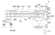
FIG. 5 is a schematic diagram showing a schematic configuration of the HMD 4 according to the fourth embodiment of the present invention. This figure is a diagram showing a schematic configuration of the HMD 4 corresponding to FIG. As shown in FIG. 5, in the HMD 4 of the present embodiment, the
図5に示すように、HMD3は、観察者の両眼(右眼と左眼)に対応した表示画像光を出射する左右一対の画像表示光学系150Cと、左右一対の輻輳角調整手段70と、を具備して構成されている。左右一対の画像表示光学系150Cのそれぞれにおいて、各画像表示光学系150Cは、第1光学系100と、第1光学系100から照射された照明光を入射して観察者の眼50へと導く左右一対の第2光学系200Cと、を具備して構成されている。なお、本図においては、便宜上左右一対の構成部品のうち観察者の右眼に対応する右側の構成部品のみを図示し、左側の構成部品については省略する。 As shown in FIG. 5, the HMD 3 includes a pair of left and right image display
第2光学系200Cを構成する導光板60は、第1光学系100に対して相対的に近い位置に配置された第1導光板61と、第1光学系100に対して相対的に遠い位置に配置された第2導光板62と、を有して構成されている。第1導光板61は、コリメーター30から出射された平行光束群を入射する光入射口61a1を一端部に有し、他端部に光を出射する光出射口61a2を有する光学面61aと、この光学面61aに対向する光学面61bと、を主面とする薄型平板のものである。第2導光板62は、第1導光板61を透過した平行光束群を入射する光入射口62a1を一端部に有し、他端部に光を出射する光出射口62a2を有する光学面62aと、この光学面62aに対向する光学面62bと、を主面とする薄型平板のものである。 The
第1導光板61の光学面61bには、光学面61aの光入射口61a1と対向する位置に緑色光用ホログラム層141Gが設けられ、光学面61aの光出射口61a2と対向する位置に緑色光用ホログラム層142Gが設けられている。 The
第2導光板62の光学面62bには、光学面62aの光入射口62a1と対向する位置に赤色光用ホログラム層141R及び青色光用ホログラム層141Bが設けられ、光学面62bの側と反対の側から赤色光用ホログラム層141R、青色光用ホログラム層141Bの順に積層されている。また、光学面62aの光出射口62a2と対向する位置に赤色光用ホログラム層142R及び青色光用ホログラム層142Bが設けられ、光学面62bの側と反対の側から赤色光用ホログラム層142R、青色光用ホログラム層142Bの順に積層されている。 The
赤色光用ホログラム層141Rに入射した平行光束群は、回折角度ΘR2で第2導光板62内部に回折される。また、緑色光用ホログラム層141Gに入射した平行光束群は、回折角度ΘG2で第1導光板61内部に回折される。また、青色光用ホログラム層141Bに入射した平行光束群は、回折角度ΘB2で第2導光板62内部に回折される。これらの回折角度ΘR2,ΘG2,ΘB2は、互いに略同一の大きさになっている(ΘR2=ΘG2=ΘB2)。なお、各導光板61,62の他端部に配置される各色光用ホログラム層142R,142G,142Bにおける回折角度についても、互いに略同一の大きさになっている。 The parallel light flux group incident on the red
このような構成により、第1光学系100から出射された緑色光が第1導光板61に入射して第1導光板61内部を全反射して第1導光板61から出射されるまでの期間における緑色光の全光路長は、第1光学系100から出射された赤色光及び青色光が第1導光板61を透過して第2導光板62に入射し第2導光板62内部を全反射して第2導光板62から出射され第1導光板61を透過するまでの期間における赤色光及び青色光のそれぞれの全光路長よりも小さくなっている。 With such a configuration, a period until the green light emitted from the first
本実施形態のHMD4によれば、導光板60を構成する第1導光板61を全反射する緑色光の全光路長が、導光板60を構成する第1導光板61を透過して第2導光板62内部を全反射する赤色光及び青色光のそれぞれの全光路長よりも小さくなる。一般に、一定の入射角度において透過型体積ホログラム素子の回折受容波長帯域は、反射型体積ホログラム素子と比較すると広い。このため、光源の波長帯域が広い場合、もしくは、光の3原色であるRGB(R:赤色光、G:緑色光、B:青色光)の各光源波長間隔が狭い場合(各色光の波長帯域がブロードである場合)、回折色分散が発生することになる。そして、この回折色分散による色収差によって、観察者の眼50に表示される表示画像の色の均一性が低下してしまうことが知られている。このため、緑色光の全光路長が赤色光及び青色光のそれぞれの全光路長よりも小さくされることより、光路差を設けて上述の回折色分散を防止することができる。したがって、透過型体積ホログラム素子を用いた場合において、観察者の眼50に表示される表示画像の色の均一性が低下することなく、自然な輻輳角Θnをもたせることにより観察者の眼精疲労を軽減することが可能となる。 According to the HMD 4 of the present embodiment, the total optical path length of the green light that totally reflects the first
1,2,3,4…HMD(頭部装着型表示装置)、10…画像表示素子、20…光源、40,60…導光板、41…反射ミラー(第1光路変更手段)、41A…第1ホログラム素子(第1光路変更手段)、42…反射ミラー(第2光路変更手段)、42A…第2ホログラム素子(第2光路変更手段)、50R…観察者の右眼、50L…観察者の左眼、61…第1導光板、62…第2導光板、70…輻輳角調整手段、100…第1光学系、141R,142R…赤色光用ホログラム層、141G,142G…緑色光用ホログラム層、141B,142B…青色光用ホログラム層、150…画像表示光学系、200…第2光学系、W…観察者の眼の幅、Θn…観察者の両眼の輻輳角1, 2, 3, 4 ... HMD (head-mounted display device), 10 ... image display element, 20 ... light source, 40, 60 ... light guide plate, 41 ... reflection mirror (first optical path changing means), 41A ... first 1 hologram element (first optical path changing means), 42 ... reflection mirror (second optical path changing means), 42A ... second hologram element (second optical path changing means), 50R ... observer's right eye, 50L ... observer's Left eye, 61 ... first light guide plate, 62 ... second light guide plate, 70 ... convergence angle adjusting means, 100 ... first optical system, 141R, 142R ... red light hologram layer, 141G, 142G ... green light hologram layer , 141B, 142B ... blue light hologram layer, 150 ... image display optical system, 200 ... second optical system, W ... observer's eye width, [theta] n ... observer's binocular convergence angle.
Claims (5)
Translated fromJapanese前記観察者の右眼に対応した表示画像光を出射する右眼用の画像表示光学系と、
前記観察者の左眼に対応した表示画像光を出射する左眼用の画像表示光学系と、
前記右眼用の画像表示光学系と前記左眼用の画像表示光学系とを前記観察者の右眼と左眼とを結ぶ線に平行に相対移動させることにより、前記観察者の両眼の輻輳角を所定の値に調整する輻輳角調整手段と、
を備えることを特徴とする頭部装着型表示装置。A head-mounted display device that is mounted on an observer's head and displays an image,
An image display optical system for the right eye that emits display image light corresponding to the right eye of the observer;
An image display optical system for the left eye that emits display image light corresponding to the left eye of the observer;
By relatively moving the image display optical system for the right eye and the image display optical system for the left eye in parallel to a line connecting the right eye and the left eye of the observer, A convergence angle adjusting means for adjusting the convergence angle to a predetermined value;
A head-mounted display device comprising:
前記各画像表示光学系は、
光を出射する光源と、
前記光源からの光を変調して前記画像表示を行う画像表示素子と、
を含む第1光学系と、
前記第1光学系から出射された表示画像光を内部全反射して導光する導光板と、
前記導光板に前記第1光学系から入射された前記表示画像光を、前記導光板の内部全反射条件を満たすように回折または反射する第1光路変更手段と、
前記第1光路変更手段から出射され前記導光板で内部全反射して導光される前記表示画像光を、前記導光板の前記内部全反射条件から外れるように回折または反射して、前記導光板から前記観察者の眼に向けて出射させる第2光路変更手段と、
を含む第2光学系と、を有し、
前記輻輳角調整手段は、前記右眼用の画像表示光学系に含まれる右眼用の第1光学系と、前記左眼用の画像表示光学系に含まれる左眼用の第1光学系と、を前記観察者の右眼と左眼とを結ぶ線に平行に相対移動させることにより、前記観察者の両眼の輻輳角を所定の値に調整することを特徴とする請求項1に記載の頭部装着型表示装置。In each of the image display optical system for the right eye and the image display optical system for the left eye,
Each of the image display optical systems is
A light source that emits light;
An image display element for performing the image display by modulating light from the light source;
A first optical system including:
A light guide plate that guides display image light emitted from the first optical system by total internal reflection;
First optical path changing means for diffracting or reflecting the display image light incident on the light guide plate from the first optical system so as to satisfy an internal total reflection condition of the light guide plate;
The display image light emitted from the first optical path changing means and guided by being totally internally reflected by the light guide plate is diffracted or reflected so as to deviate from the internal total reflection condition of the light guide plate, and the light guide plate Second optical path changing means for emitting from the eye toward the observer's eyes,
A second optical system including
The convergence angle adjusting means includes a first optical system for the right eye included in the image display optical system for the right eye, and a first optical system for the left eye included in the image display optical system for the left eye. The angle of convergence of both eyes of the observer is adjusted to a predetermined value by relatively moving in parallel with a line connecting the right eye and the left eye of the observer. Head-mounted display device.
前記各第1光路変更手段は、前記表示画像光を回折する第1ホログラム素子を有し、
前記各第2光路変更手段は、前記第1ホログラム素子から出射され前記導光板内部で全反射して導光される前記表示画像光を前記観察者の眼に向けて回折する第2ホログラム素子を有することを特徴とする請求項2または3に記載の頭部装着型表示装置。In each of the second optical system for the right eye included in the image display optical system for the right eye and the second optical system for the left eye included in the image display optical system for the left eye,
Each of the first optical path changing means has a first hologram element that diffracts the display image light,
Each of the second optical path changing means includes a second hologram element that diffracts the display image light emitted from the first hologram element and guided by being totally reflected inside the light guide plate toward the eyes of the observer. The head-mounted display device according to claim 2, wherein the head-mounted display device is provided.
前記赤色光用ホログラム層、前記緑色光用ホログラム層、前記青色光用ホログラム層は、同一の入射角で入射される互いに異なる波長域の前記表示画像光を、それぞれ略同一の回折角にて回折することを特徴とする請求項4に記載の頭部装着型表示装置。The first hologram element and the second hologram element selectively diffract the red light hologram layer for selectively diffracting the display image light in the red light wavelength region and the display image light in the green light wavelength region. A green light hologram layer, and a blue light hologram layer that selectively diffracts display image light in a wavelength range of blue light,
The red light hologram layer, the green light hologram layer, and the blue light hologram layer diffract the display image light having different wavelength ranges incident at the same incident angle at substantially the same diffraction angle. The head-mounted display device according to claim 4, wherein:
Priority Applications (1)
| Application Number | Priority Date | Filing Date | Title |
|---|---|---|---|
| JP2009123873AJP2010271565A (en) | 2009-05-22 | 2009-05-22 | Head-mounted display device |
Applications Claiming Priority (1)
| Application Number | Priority Date | Filing Date | Title |
|---|---|---|---|
| JP2009123873AJP2010271565A (en) | 2009-05-22 | 2009-05-22 | Head-mounted display device |
Publications (1)
| Publication Number | Publication Date |
|---|---|
| JP2010271565Atrue JP2010271565A (en) | 2010-12-02 |
Family
ID=43419626
Family Applications (1)
| Application Number | Title | Priority Date | Filing Date |
|---|---|---|---|
| JP2009123873AWithdrawnJP2010271565A (en) | 2009-05-22 | 2009-05-22 | Head-mounted display device |
Country Status (1)
| Country | Link |
|---|---|
| JP (1) | JP2010271565A (en) |
Cited By (32)
| Publication number | Priority date | Publication date | Assignee | Title |
|---|---|---|---|---|
| CN102809821A (en)* | 2011-06-01 | 2012-12-05 | 索尼公司 | Display apparatus |
| JP2013057782A (en)* | 2011-09-08 | 2013-03-28 | Seiko Epson Corp | Electronic equipment |
| JP2015049376A (en)* | 2013-09-02 | 2015-03-16 | セイコーエプソン株式会社 | Optical device and image display apparatus |
| JP2015194550A (en)* | 2014-03-31 | 2015-11-05 | セイコーエプソン株式会社 | Optical device, image projection apparatus, and electronic apparatus |
| JP2015194654A (en)* | 2014-03-31 | 2015-11-05 | セイコーエプソン株式会社 | Optical device, image projection apparatus, and electronic equipment |
| WO2017038350A1 (en)* | 2015-09-02 | 2017-03-09 | ソニー株式会社 | Optical device and method for producing same, and display device |
| JP2017531840A (en)* | 2014-09-29 | 2017-10-26 | マジック リープ,インコーポレイティド | Structure and method for outputting light of different wavelengths from a waveguide |
| JP2018028703A (en)* | 2013-11-27 | 2018-02-22 | マジック リープ, インコーポレイテッドMagic Leap,Inc. | Virtual and augmented reality system and method |
| WO2018133100A1 (en)* | 2017-01-23 | 2018-07-26 | 深圳市大疆创新科技有限公司 | Wearable device |
| JP2018523852A (en)* | 2015-09-13 | 2018-08-23 | シェンジェン ロイオル テクノロジーズ カンパニー リミテッドShenzhen Royole Technologies Co., Ltd. | Optical module, optical device and wearable display device |
| WO2018190007A1 (en)* | 2017-04-13 | 2018-10-18 | ソニー株式会社 | Image display device |
| JP2019501564A (en)* | 2015-11-04 | 2019-01-17 | マジック リープ, インコーポレイテッドMagic Leap,Inc. | Dynamic display calibration based on eye tracking |
| WO2019026720A1 (en)* | 2017-08-04 | 2019-02-07 | 株式会社エガリム | Polarization beam splitter, surface light source device, and display device |
| WO2019088071A1 (en)* | 2017-11-02 | 2019-05-09 | マクセル株式会社 | Virtual image display device and head mounted display using same |
| WO2020080117A1 (en)* | 2018-10-15 | 2020-04-23 | ソニー株式会社 | Image display device, head-mounted display, method for manufacturing image display device, and method for adjusting image display device |
| US10690826B2 (en) | 2015-06-15 | 2020-06-23 | Magic Leap, Inc. | Virtual and augmented reality systems and methods |
| US10895784B2 (en) | 2016-12-14 | 2021-01-19 | Magic Leap, Inc. | Patterning of liquid crystals using soft-imprint replication of surface alignment patterns |
| US10921630B2 (en) | 2016-11-18 | 2021-02-16 | Magic Leap, Inc. | Spatially variable liquid crystal diffraction gratings |
| US10962855B2 (en) | 2017-02-23 | 2021-03-30 | Magic Leap, Inc. | Display system with variable power reflector |
| US10969588B2 (en) | 2015-03-16 | 2021-04-06 | Magic Leap, Inc. | Methods and systems for diagnosing contrast sensitivity |
| US11067860B2 (en) | 2016-11-18 | 2021-07-20 | Magic Leap, Inc. | Liquid crystal diffractive devices with nano-scale pattern and methods of manufacturing the same |
| US11073695B2 (en) | 2017-03-21 | 2021-07-27 | Magic Leap, Inc. | Eye-imaging apparatus using diffractive optical elements |
| US11086125B2 (en) | 2016-05-12 | 2021-08-10 | Magic Leap, Inc. | Distributed light manipulation over imaging waveguide |
| US11106041B2 (en) | 2016-04-08 | 2021-08-31 | Magic Leap, Inc. | Augmented reality systems and methods with variable focus lens elements |
| US20210302802A1 (en)* | 2016-11-18 | 2021-09-30 | Magic Leap, Inc. | Waveguide light multiplexer using crossed gratings |
| US11204462B2 (en) | 2017-01-23 | 2021-12-21 | Magic Leap, Inc. | Eyepiece for virtual, augmented, or mixed reality systems |
| US11237393B2 (en) | 2018-11-20 | 2022-02-01 | Magic Leap, Inc. | Eyepieces for augmented reality display system |
| US11347063B2 (en) | 2017-12-15 | 2022-05-31 | Magic Leap, Inc. | Eyepieces for augmented reality display system |
| US11650423B2 (en) | 2019-06-20 | 2023-05-16 | Magic Leap, Inc. | Eyepieces for augmented reality display system |
| US11668989B2 (en) | 2016-12-08 | 2023-06-06 | Magic Leap, Inc. | Diffractive devices based on cholesteric liquid crystal |
| US11841481B2 (en) | 2017-09-21 | 2023-12-12 | Magic Leap, Inc. | Augmented reality display with waveguide configured to capture images of eye and/or environment |
| WO2024055138A1 (en)* | 2022-09-13 | 2024-03-21 | 合肥英睿系统技术有限公司 | Combined sighting system and sight imaging system thereof |
- 2009
- 2009-05-22JPJP2009123873Apatent/JP2010271565A/ennot_activeWithdrawn
Cited By (94)
| Publication number | Priority date | Publication date | Assignee | Title |
|---|---|---|---|---|
| CN102809821A (en)* | 2011-06-01 | 2012-12-05 | 索尼公司 | Display apparatus |
| JP2013057782A (en)* | 2011-09-08 | 2013-03-28 | Seiko Epson Corp | Electronic equipment |
| JP2015049376A (en)* | 2013-09-02 | 2015-03-16 | セイコーエプソン株式会社 | Optical device and image display apparatus |
| JP2018028703A (en)* | 2013-11-27 | 2018-02-22 | マジック リープ, インコーポレイテッドMagic Leap,Inc. | Virtual and augmented reality system and method |
| JP2018060214A (en)* | 2013-11-27 | 2018-04-12 | マジック リープ, インコーポレイテッドMagic Leap,Inc. | Virtual and augmented reality systems and methods |
| JP2015194550A (en)* | 2014-03-31 | 2015-11-05 | セイコーエプソン株式会社 | Optical device, image projection apparatus, and electronic apparatus |
| JP2015194654A (en)* | 2014-03-31 | 2015-11-05 | セイコーエプソン株式会社 | Optical device, image projection apparatus, and electronic equipment |
| JP2017531840A (en)* | 2014-09-29 | 2017-10-26 | マジック リープ,インコーポレイティド | Structure and method for outputting light of different wavelengths from a waveguide |
| US12181676B2 (en) | 2014-09-29 | 2024-12-31 | Magic Leap, Inc. | Architectures and methods for outputting different wavelength light out of waveguides |
| US11796814B2 (en) | 2014-09-29 | 2023-10-24 | Magic Leap, Inc. | Architectures and methods for outputting different wavelength light out of waveguides |
| US11042032B2 (en) | 2014-09-29 | 2021-06-22 | Magic Leap, Inc. | Architectures and methods for outputting different wavelength light out of waveguides |
| US11016300B2 (en) | 2014-09-29 | 2021-05-25 | Magic Leap, Inc. | Architectures and methods for outputting different wavelength light out of waveguides |
| US10901219B2 (en) | 2014-09-29 | 2021-01-26 | Magic Leap, Inc. | Architectures and methods for outputting different wavelength light out of waveguides |
| US11256096B2 (en) | 2015-03-16 | 2022-02-22 | Magic Leap, Inc. | Methods and systems for diagnosing and treating presbyopia |
| US11747627B2 (en) | 2015-03-16 | 2023-09-05 | Magic Leap, Inc. | Augmented and virtual reality display systems and methods for diagnosing health conditions based on visual fields |
| US12345892B2 (en) | 2015-03-16 | 2025-07-01 | Magic Leap, Inc. | Augmented and virtual reality display systems and methods for diagnosing health conditions based on visual fields |
| US11156835B2 (en) | 2015-03-16 | 2021-10-26 | Magic Leap, Inc. | Methods and systems for diagnosing and treating health ailments |
| US11474359B2 (en) | 2015-03-16 | 2022-10-18 | Magic Leap, Inc. | Augmented and virtual reality display systems and methods for diagnosing health conditions based on visual fields |
| US10983351B2 (en) | 2015-03-16 | 2021-04-20 | Magic Leap, Inc. | Augmented and virtual reality display systems and methods for diagnosing health conditions based on visual fields |
| US10969588B2 (en) | 2015-03-16 | 2021-04-06 | Magic Leap, Inc. | Methods and systems for diagnosing contrast sensitivity |
| US12326585B2 (en) | 2015-06-15 | 2025-06-10 | Magic Leap, Inc. | Display system with optical elements for in-coupling multiplexed light streams |
| US10690826B2 (en) | 2015-06-15 | 2020-06-23 | Magic Leap, Inc. | Virtual and augmented reality systems and methods |
| US11067732B2 (en) | 2015-06-15 | 2021-07-20 | Magic Leap, Inc. | Virtual and augmented reality systems and methods |
| US11789189B2 (en) | 2015-06-15 | 2023-10-17 | Magic Leap, Inc. | Display system with optical elements for in-coupling multiplexed light streams |
| US11733443B2 (en) | 2015-06-15 | 2023-08-22 | Magic Leap, Inc. | Virtual and augmented reality systems and methods |
| US10948642B2 (en) | 2015-06-15 | 2021-03-16 | Magic Leap, Inc. | Display system with optical elements for in-coupling multiplexed light streams |
| WO2017038350A1 (en)* | 2015-09-02 | 2017-03-09 | ソニー株式会社 | Optical device and method for producing same, and display device |
| US11016306B2 (en) | 2015-09-02 | 2021-05-25 | Sony Corporation | Optical device and method for producing the same, and display device |
| CN107924061B (en)* | 2015-09-02 | 2020-11-17 | 索尼公司 | Optical device, method of manufacturing the same, and display device |
| CN107924061A (en)* | 2015-09-02 | 2018-04-17 | 索尼公司 | Optical devices and its manufacture method and display device |
| JP2018523852A (en)* | 2015-09-13 | 2018-08-23 | シェンジェン ロイオル テクノロジーズ カンパニー リミテッドShenzhen Royole Technologies Co., Ltd. | Optical module, optical device and wearable display device |
| US11898836B2 (en) | 2015-11-04 | 2024-02-13 | Magic Leap, Inc. | Light field display metrology |
| US11454495B2 (en) | 2015-11-04 | 2022-09-27 | Magic Leap, Inc. | Dynamic display calibration based on eye-tracking |
| JP2019501564A (en)* | 2015-11-04 | 2019-01-17 | マジック リープ, インコーポレイテッドMagic Leap,Inc. | Dynamic display calibration based on eye tracking |
| US11226193B2 (en) | 2015-11-04 | 2022-01-18 | Magic Leap, Inc. | Light field display metrology |
| US11536559B2 (en) | 2015-11-04 | 2022-12-27 | Magic Leap, Inc. | Light field display metrology |
| US12287189B2 (en) | 2015-11-04 | 2025-04-29 | Magic Leap, Inc. | Light field display metrology |
| US11106041B2 (en) | 2016-04-08 | 2021-08-31 | Magic Leap, Inc. | Augmented reality systems and methods with variable focus lens elements |
| US11614626B2 (en) | 2016-04-08 | 2023-03-28 | Magic Leap, Inc. | Augmented reality systems and methods with variable focus lens elements |
| US11314091B2 (en) | 2016-05-12 | 2022-04-26 | Magic Leap, Inc. | Wavelength multiplexing in waveguides |
| US11086125B2 (en) | 2016-05-12 | 2021-08-10 | Magic Leap, Inc. | Distributed light manipulation over imaging waveguide |
| US12001091B2 (en) | 2016-11-18 | 2024-06-04 | Magic Leap, Inc. | Spatially variable liquid crystal diffraction gratings |
| US11067860B2 (en) | 2016-11-18 | 2021-07-20 | Magic Leap, Inc. | Liquid crystal diffractive devices with nano-scale pattern and methods of manufacturing the same |
| US20210302802A1 (en)* | 2016-11-18 | 2021-09-30 | Magic Leap, Inc. | Waveguide light multiplexer using crossed gratings |
| US11609480B2 (en) | 2016-11-18 | 2023-03-21 | Magic Leap, Inc. | Waveguide light multiplexer using crossed gratings |
| US12044952B2 (en) | 2016-11-18 | 2024-07-23 | Magic Leap, Inc. | Waveguide light multiplexer using crossed gratings |
| US10921630B2 (en) | 2016-11-18 | 2021-02-16 | Magic Leap, Inc. | Spatially variable liquid crystal diffraction gratings |
| US12222594B2 (en) | 2016-11-18 | 2025-02-11 | Magic Leap, Inc. | Spatially variable liquid crystal diffraction gratings |
| US12353101B2 (en) | 2016-11-18 | 2025-07-08 | Magic Leap, Inc. | Liquid crystal diffractive devices with nano-scale pattern and methods of manufacturing the same |
| US11586065B2 (en) | 2016-11-18 | 2023-02-21 | Magic Leap, Inc. | Spatially variable liquid crystal diffraction gratings |
| US11693282B2 (en) | 2016-11-18 | 2023-07-04 | Magic Leap, Inc. | Liquid crystal diffractive devices with nano-scale pattern and methods of manufacturing the same |
| US11378864B2 (en) | 2016-11-18 | 2022-07-05 | Magic Leap, Inc. | Waveguide light multiplexer using crossed gratings |
| US11668989B2 (en) | 2016-12-08 | 2023-06-06 | Magic Leap, Inc. | Diffractive devices based on cholesteric liquid crystal |
| US10895784B2 (en) | 2016-12-14 | 2021-01-19 | Magic Leap, Inc. | Patterning of liquid crystals using soft-imprint replication of surface alignment patterns |
| US11567371B2 (en) | 2016-12-14 | 2023-01-31 | Magic Leap, Inc. | Patterning of liquid crystals using soft-imprint replication of surface alignment patterns |
| US12216311B2 (en) | 2017-01-23 | 2025-02-04 | Magic Leap, Inc. | Eyepiece for virtual, augmented, or mixed reality systems |
| US11733456B2 (en) | 2017-01-23 | 2023-08-22 | Magic Leap, Inc. | Eyepiece for virtual, augmented, or mixed reality systems |
| WO2018133100A1 (en)* | 2017-01-23 | 2018-07-26 | 深圳市大疆创新科技有限公司 | Wearable device |
| US11204462B2 (en) | 2017-01-23 | 2021-12-21 | Magic Leap, Inc. | Eyepiece for virtual, augmented, or mixed reality systems |
| US11300844B2 (en) | 2017-02-23 | 2022-04-12 | Magic Leap, Inc. | Display system with variable power reflector |
| US11774823B2 (en) | 2017-02-23 | 2023-10-03 | Magic Leap, Inc. | Display system with variable power reflector |
| US10962855B2 (en) | 2017-02-23 | 2021-03-30 | Magic Leap, Inc. | Display system with variable power reflector |
| US12429698B2 (en) | 2017-03-21 | 2025-09-30 | Magic Leap, Inc. | Eye-imaging apparatus using diffractive optical elements |
| US12055726B2 (en) | 2017-03-21 | 2024-08-06 | Magic Leap, Inc. | Eye-imaging apparatus using diffractive optical elements |
| US11754840B2 (en) | 2017-03-21 | 2023-09-12 | Magic Leap, Inc. | Eye-imaging apparatus using diffractive optical elements |
| US11073695B2 (en) | 2017-03-21 | 2021-07-27 | Magic Leap, Inc. | Eye-imaging apparatus using diffractive optical elements |
| KR20190139862A (en)* | 2017-04-13 | 2019-12-18 | 소니 주식회사 | Image display |
| WO2018190007A1 (en)* | 2017-04-13 | 2018-10-18 | ソニー株式会社 | Image display device |
| KR102519000B1 (en) | 2017-04-13 | 2023-04-07 | 소니그룹주식회사 | image display device |
| US11143871B2 (en) | 2017-04-13 | 2021-10-12 | Sony Corporation | Image display apparatus |
| JPWO2019026720A1 (en)* | 2017-08-04 | 2020-07-27 | 株式会社エガリム | Polarization beam splitter, surface light source device or display device |
| US11789285B2 (en) | 2017-08-04 | 2023-10-17 | Egarim Corporation Japan | Polarization beam splitter, surface light source device, and display device |
| WO2019026720A1 (en)* | 2017-08-04 | 2019-02-07 | 株式会社エガリム | Polarization beam splitter, surface light source device, and display device |
| US12298517B2 (en) | 2017-09-21 | 2025-05-13 | Magic Leap, Inc. | Augmented reality display with waveguide configured to capture images of eye and/or environment |
| US11841481B2 (en) | 2017-09-21 | 2023-12-12 | Magic Leap, Inc. | Augmented reality display with waveguide configured to capture images of eye and/or environment |
| US11297304B2 (en) | 2017-11-02 | 2022-04-05 | Maxell, Ltd. | Virtual image display device and head mounted display using same |
| WO2019088071A1 (en)* | 2017-11-02 | 2019-05-09 | マクセル株式会社 | Virtual image display device and head mounted display using same |
| US11991345B2 (en) | 2017-11-02 | 2024-05-21 | Maxell, Ltd. | Virtual image display device and head mounted display using same |
| JP7431267B2 (en) | 2017-11-02 | 2024-02-14 | マクセル株式会社 | Virtual image display device and head-mounted display using the same |
| JP7036572B2 (en) | 2017-11-02 | 2022-03-15 | マクセル株式会社 | Virtual image display device and head-mounted display using it |
| US20220150466A1 (en)* | 2017-11-02 | 2022-05-12 | Maxell, Ltd. | Virtual image display device and head mounted display using same |
| JP2022082551A (en)* | 2017-11-02 | 2022-06-02 | マクセル株式会社 | Virtual image display device and head-mounted display using the same |
| JP2019086556A (en)* | 2017-11-02 | 2019-06-06 | マクセル株式会社 | Virtual image display device and head mounted display using the same |
| US11977233B2 (en) | 2017-12-15 | 2024-05-07 | Magic Leap, Inc. | Eyepieces for augmented reality display system |
| US12181682B2 (en) | 2017-12-15 | 2024-12-31 | Magic Leap, Inc. | Eyepieces for augmented reality display system |
| US11347063B2 (en) | 2017-12-15 | 2022-05-31 | Magic Leap, Inc. | Eyepieces for augmented reality display system |
| WO2020080117A1 (en)* | 2018-10-15 | 2020-04-23 | ソニー株式会社 | Image display device, head-mounted display, method for manufacturing image display device, and method for adjusting image display device |
| US12306407B2 (en) | 2018-11-20 | 2025-05-20 | Magic Leap, Inc. | Eyepieces for augmented reality display system |
| US11237393B2 (en) | 2018-11-20 | 2022-02-01 | Magic Leap, Inc. | Eyepieces for augmented reality display system |
| US11754841B2 (en) | 2018-11-20 | 2023-09-12 | Magic Leap, Inc. | Eyepieces for augmented reality display system |
| US12181678B2 (en) | 2019-06-20 | 2024-12-31 | Magic Leap, Inc. | Eyepieces for augmented reality display system |
| US11650423B2 (en) | 2019-06-20 | 2023-05-16 | Magic Leap, Inc. | Eyepieces for augmented reality display system |
| US12379600B2 (en) | 2019-06-20 | 2025-08-05 | Magic Leap, Inc. | Eyepieces for augmented reality display system |
| WO2024055138A1 (en)* | 2022-09-13 | 2024-03-21 | 合肥英睿系统技术有限公司 | Combined sighting system and sight imaging system thereof |
Similar Documents
| Publication | Publication Date | Title |
|---|---|---|
| JP2010271565A (en) | Head-mounted display device | |
| US9568730B2 (en) | Optical device including diffraction elements for diffracting light inside of a light guide, image projecting apparatus, and electronic device | |
| JP6394393B2 (en) | Image display device, image generation device, and transmissive spatial light modulation device | |
| JP6035793B2 (en) | Image display device and image generation device | |
| JP6197295B2 (en) | Optical device and image display apparatus | |
| JP7275829B2 (en) | Display device and image display method | |
| JP5545076B2 (en) | Image display device and optical device | |
| US7499216B2 (en) | Wide field-of-view binocular device | |
| JP6232863B2 (en) | Optical device and image display apparatus | |
| US8638499B2 (en) | Image display apparatus | |
| JP4395802B2 (en) | Image display device | |
| CN109581660B (en) | Virtual image display device | |
| JP5678709B2 (en) | Display device | |
| US20100103078A1 (en) | Head-mounted display apparatus | |
| JP2019510251A (en) | Double-sided imaging light guide | |
| JP2019507366A (en) | Double-sided imaging light guide with embedded dichroic filter | |
| JP2018054978A (en) | Virtual image display device and manufacturing method thereof | |
| JP2013057782A (en) | Electronic equipment | |
| WO2005093493A1 (en) | Optical device and virtual image display device | |
| JP2014222302A (en) | Display device | |
| JP6450944B2 (en) | Display device | |
| US10871651B2 (en) | Display device and light-guiding device | |
| JP2012018414A (en) | Head-mounted type display | |
| JP6507566B2 (en) | Image display device and wearable image display device | |
| US11640060B2 (en) | Head-mounted display |
Legal Events
| Date | Code | Title | Description |
|---|---|---|---|
| A300 | Withdrawal of application because of no request for examination | Free format text:JAPANESE INTERMEDIATE CODE: A300 Effective date:20120807 |