JP2010263500A - Video processing system, photographing apparatus, and video processing method - Google Patents
Video processing system, photographing apparatus, and video processing methodDownload PDFInfo
- Publication number
- JP2010263500A JP2010263500AJP2009113931AJP2009113931AJP2010263500AJP 2010263500 AJP2010263500 AJP 2010263500AJP 2009113931 AJP2009113931 AJP 2009113931AJP 2009113931 AJP2009113931 AJP 2009113931AJP 2010263500 AJP2010263500 AJP 2010263500A
- Authority
- JP
- Japan
- Prior art keywords
- video data
- video
- data
- unit
- generated
- Prior art date
- Legal status (The legal status is an assumption and is not a legal conclusion. Google has not performed a legal analysis and makes no representation as to the accuracy of the status listed.)
- Withdrawn
Links
Images


Classifications
- B—PERFORMING OPERATIONS; TRANSPORTING
- B60—VEHICLES IN GENERAL
- B60Q—ARRANGEMENT OF SIGNALLING OR LIGHTING DEVICES, THE MOUNTING OR SUPPORTING THEREOF OR CIRCUITS THEREFOR, FOR VEHICLES IN GENERAL
- B60Q9/00—Arrangement or adaptation of signal devices not provided for in one of main groups B60Q1/00 - B60Q7/00, e.g. haptic signalling
- B60Q9/002—Arrangement or adaptation of signal devices not provided for in one of main groups B60Q1/00 - B60Q7/00, e.g. haptic signalling for parking purposes, e.g. for warning the driver that his vehicle has contacted or is about to contact an obstacle
- B60Q9/004—Arrangement or adaptation of signal devices not provided for in one of main groups B60Q1/00 - B60Q7/00, e.g. haptic signalling for parking purposes, e.g. for warning the driver that his vehicle has contacted or is about to contact an obstacle using wave sensors
- B60Q9/005—Arrangement or adaptation of signal devices not provided for in one of main groups B60Q1/00 - B60Q7/00, e.g. haptic signalling for parking purposes, e.g. for warning the driver that his vehicle has contacted or is about to contact an obstacle using wave sensors using a video camera
- G—PHYSICS
- G06—COMPUTING OR CALCULATING; COUNTING
- G06T—IMAGE DATA PROCESSING OR GENERATION, IN GENERAL
- G06T3/00—Geometric image transformations in the plane of the image
- G06T3/40—Scaling of whole images or parts thereof, e.g. expanding or contracting
- G06T3/4038—Image mosaicing, e.g. composing plane images from plane sub-images
- G—PHYSICS
- G06—COMPUTING OR CALCULATING; COUNTING
- G06V—IMAGE OR VIDEO RECOGNITION OR UNDERSTANDING
- G06V10/00—Arrangements for image or video recognition or understanding
- G06V10/10—Image acquisition
- G06V10/12—Details of acquisition arrangements; Constructional details thereof
- G06V10/14—Optical characteristics of the device performing the acquisition or on the illumination arrangements
- G06V10/147—Details of sensors, e.g. sensor lenses
- G—PHYSICS
- G06—COMPUTING OR CALCULATING; COUNTING
- G06V—IMAGE OR VIDEO RECOGNITION OR UNDERSTANDING
- G06V20/00—Scenes; Scene-specific elements
- G06V20/50—Context or environment of the image
- G06V20/56—Context or environment of the image exterior to a vehicle by using sensors mounted on the vehicle
- H—ELECTRICITY
- H04—ELECTRIC COMMUNICATION TECHNIQUE
- H04N—PICTORIAL COMMUNICATION, e.g. TELEVISION
- H04N19/00—Methods or arrangements for coding, decoding, compressing or decompressing digital video signals
- H04N19/10—Methods or arrangements for coding, decoding, compressing or decompressing digital video signals using adaptive coding
- H04N19/102—Methods or arrangements for coding, decoding, compressing or decompressing digital video signals using adaptive coding characterised by the element, parameter or selection affected or controlled by the adaptive coding
- H04N19/103—Selection of coding mode or of prediction mode
- H—ELECTRICITY
- H04—ELECTRIC COMMUNICATION TECHNIQUE
- H04N—PICTORIAL COMMUNICATION, e.g. TELEVISION
- H04N19/00—Methods or arrangements for coding, decoding, compressing or decompressing digital video signals
- H04N19/10—Methods or arrangements for coding, decoding, compressing or decompressing digital video signals using adaptive coding
- H04N19/134—Methods or arrangements for coding, decoding, compressing or decompressing digital video signals using adaptive coding characterised by the element, parameter or criterion affecting or controlling the adaptive coding
- H04N19/167—Position within a video image, e.g. region of interest [ROI]
- H—ELECTRICITY
- H04—ELECTRIC COMMUNICATION TECHNIQUE
- H04N—PICTORIAL COMMUNICATION, e.g. TELEVISION
- H04N19/00—Methods or arrangements for coding, decoding, compressing or decompressing digital video signals
- H04N19/10—Methods or arrangements for coding, decoding, compressing or decompressing digital video signals using adaptive coding
- H04N19/169—Methods or arrangements for coding, decoding, compressing or decompressing digital video signals using adaptive coding characterised by the coding unit, i.e. the structural portion or semantic portion of the video signal being the object or the subject of the adaptive coding
- H04N19/17—Methods or arrangements for coding, decoding, compressing or decompressing digital video signals using adaptive coding characterised by the coding unit, i.e. the structural portion or semantic portion of the video signal being the object or the subject of the adaptive coding the unit being an image region, e.g. an object
- H—ELECTRICITY
- H04—ELECTRIC COMMUNICATION TECHNIQUE
- H04N—PICTORIAL COMMUNICATION, e.g. TELEVISION
- H04N19/00—Methods or arrangements for coding, decoding, compressing or decompressing digital video signals
- H04N19/60—Methods or arrangements for coding, decoding, compressing or decompressing digital video signals using transform coding
- H04N19/63—Methods or arrangements for coding, decoding, compressing or decompressing digital video signals using transform coding using sub-band based transform, e.g. wavelets
Landscapes
- Engineering & Computer Science (AREA)
- Multimedia (AREA)
- Signal Processing (AREA)
- Theoretical Computer Science (AREA)
- Physics & Mathematics (AREA)
- General Physics & Mathematics (AREA)
- Radar, Positioning & Navigation (AREA)
- General Health & Medical Sciences (AREA)
- Health & Medical Sciences (AREA)
- Vascular Medicine (AREA)
- Remote Sensing (AREA)
- Transportation (AREA)
- Human Computer Interaction (AREA)
- Mechanical Engineering (AREA)
- Closed-Circuit Television Systems (AREA)
- Image Processing (AREA)
- Studio Devices (AREA)
- Image Analysis (AREA)
Abstract
Translated fromJapaneseDescription
Translated fromJapanese本発明は、複数の撮影装置(例えば、カメラ)で周辺の映像を撮影し、撮影した映像を合成処理して表示装置に表示させる映像処理システムに関する。 The present invention relates to a video processing system that captures peripheral images with a plurality of imaging devices (for example, cameras), combines the captured images, and displays them on a display device.
近年、車両に搭載された複数台のカメラによって、運転者の死角となる車両の周辺部を映し出し、車室内に搭載された表示装置(モニタ)に表示することで運転者の安全運転を支援する装置が提案されている。 In recent years, a plurality of cameras mounted on a vehicle are used to project a driver's blind spot and display it on a display device (monitor) mounted in the passenger compartment, thereby assisting the driver's safe driving. A device has been proposed.
しかしながら、より高精細な映像を表示するため、カメラの解像度を上げると、カメラの映像を処理する映像処理装置に送信するデータ量が大幅に増加する。また、車両に搭載するカメラの台数を増やしても同様のことが言える。このため、各カメラと映像処理装置とをつなぐ伝送路の帯域幅によって送信可能なデータ量が制限される場合がある。 However, when the resolution of the camera is increased in order to display a higher-definition video, the amount of data transmitted to the video processing device that processes the video from the camera is greatly increased. The same can be said even if the number of cameras mounted on the vehicle is increased. For this reason, the amount of data that can be transmitted may be limited by the bandwidth of the transmission path connecting each camera and the video processing device.
特許文献1及び2には、画像取込み装置又はカメラ制御装置から、画像受信装置へ送信されるデータ量を削減する技術が開示されている。特許文献1では、画像受信装置側で、生成する画像のレイアウト情報を作成して画像取込み装置に送信する。画像取込み装置は、取得したレイアウト情報に従って、取り込んだ画像データの切り出しを行い、切り出した画像を画像受信装置に送信している。また、特許文献2では、カメラ制御装置が、カメラの撮影方向とズーム倍率を検出して、カメラによって撮影された映像を所望の解像度およびフレームレートの映像に変換している。変換した映像は、カメラ制御装置から端末に送信される。端末は、各カメラ制御装置から送信された映像を合成してモニタに表示している。
右左折、車線変更、車庫入れ等、運転者の運転状況に応じて生成する生成映像のパターンを切り替えることで運転者の利便性が向上するが、生成映像のパターンに応じて、各カメラ映像の使用部分や、必要な映像の解像度が異なってくる。例えば、図1に示すようにカメラに近い側では、映像の画素当たりの地面の面積が狭いが、カメラから離れるに従って、映像の画素当たりの地面の面積が広くなってくる。従って、例えば、俯瞰映像を生成すると、カメラから遠くなるに従い、少ない画素から広い映像を生成する必要があり、映像が粗くなる。
このため、カメラ等の撮影装置から映像処理装置へのデータ量を削減しつつ、複数種類の生成映像を高精細に生成するためには、生成映像に使用される部分ごとに解像度を調整したカメラ映像を映像処理装置に送信する必要がある。The convenience of the driver is improved by switching the pattern of the generated video generated according to the driving situation of the driver, such as turning left and right, changing lanes, entering the garage, etc., but depending on the pattern of the generated video, each camera video The used part and the required video resolution will vary. For example, as shown in FIG. 1, on the side closer to the camera, the area of the ground per pixel of the video is narrow, but as the distance from the camera increases, the area of the ground per pixel of the video increases. Therefore, for example, when an overhead image is generated, it is necessary to generate a wide image from a small number of pixels as the distance from the camera increases, and the image becomes rough.
For this reason, in order to generate a plurality of types of generated video with high definition while reducing the amount of data from the imaging device such as a camera to the video processing device, a camera whose resolution is adjusted for each part used in the generated video The video needs to be transmitted to the video processing device.
本発明は上記事情に鑑みてなされたものであり、撮影装置から送信されるデータ量の削減と、高品質な生成映像の生成とを両立する映像処理システム、撮影装置及び映像処理方法を提供することを目的とする。 The present invention has been made in view of the above circumstances, and provides an image processing system, an image capturing apparatus, and an image processing method that can achieve both reduction in the amount of data transmitted from an image capturing apparatus and generation of a high-quality generated image. For the purpose.
本明細書に開示の映像処理システムは、映像データを表示可能な表示装置と、車両周辺を撮影可能な複数の撮影装置と、車内伝送路経由で前記複数の撮影装置と連携し、撮影された複数の映像データから複数種類の生成映像データを生成する映像処理装置とを備えた映像処理システムであって、前記複数の撮影装置は、それぞれ、映像データの分割した複数の領域を識別する領域情報と、生成映像データの生成の際に前記映像データの各領域に要求される解像度に基づいて前記各領域ごとに算出された重要度とを記憶した記憶部と、前記重要度を参照して、撮影された映像データの各領域を重要度に応じた圧縮率で圧縮する映像圧縮部と、前記圧縮された映像データを前記車内伝送路経由で前記映像処理装置に送信する送信部とを備え、前記映像処理装置は、前記複数の撮影装置から送信される、前記圧縮された映像データを入力する入力部と、入力した複数の圧縮された映像データに基づいて、前記表示装置に表示する映像データを生成する映像生成部と、生成した映像データを前記表示装置に送信する送信部とを備え、前記表示装置は、前記映像処理装置から送信された前記生成映像データを受信する受信部と、受信した生成映像データを表示する表示部とを備えている。 The video processing system disclosed in the present specification was shot in cooperation with a display device capable of displaying video data, a plurality of photographing devices capable of photographing the periphery of the vehicle, and the plurality of photographing devices via an in-vehicle transmission path. A video processing system including a video processing device that generates a plurality of types of generated video data from a plurality of video data, wherein each of the plurality of imaging devices identifies a plurality of regions obtained by dividing the video data A storage unit that stores the importance calculated for each region based on the resolution required for each region of the video data when generating the generated video data, and referring to the importance, A video compression unit that compresses each area of the captured video data at a compression rate according to the importance, and a transmission unit that transmits the compressed video data to the video processing device via the in-vehicle transmission path, Above An image processing device includes: an input unit that inputs the compressed video data transmitted from the plurality of imaging devices; and video data to be displayed on the display device based on the plurality of input compressed video data. A video generation unit for generating and a transmission unit for transmitting the generated video data to the display device, wherein the display device receives the generated video data transmitted from the video processing device; And a display unit for displaying the generated video data.
本明細書に開示の映像処理システムによれば、撮影装置から送信されるデータ量の削減と、高品質な生成映像の生成とを両立する映像処理システムを提供することができる。 According to the video processing system disclosed in this specification, it is possible to provide a video processing system that achieves both a reduction in the amount of data transmitted from the imaging device and generation of high-quality generated video.
以下、添付図面を参照しながら本発明の好適な実施例を説明する。 Hereinafter, preferred embodiments of the present invention will be described with reference to the accompanying drawings.
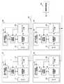
本実施例の映像処理システム1は、図2に示すように撮影装置100と、映像処理装置200と、操作部310と、表示装置320とを備えている。撮影装置100は、第1撮影部110と、第2撮影部120と、第3撮影部130と、第4撮影部140とを備えている。また、映像処理装置200は、ネットワークインターフェース部(以下、インターフェースをI/Fと略記する)210と、映像生成部220と、制御部230と、記憶部240と、送信部250とを備えている。表示装置320は、受信部321と、表示部322とを備えている。また、撮影装置100と、映像処理装置200とはLAN等のネットワーク150で接続されている。 As shown in FIG. 2, the
図3を参照しながら撮影装置100の詳細について説明する。なお、第1撮影部110〜第4撮影部140は、ほぼ同一の構成を備えているため、以下では代表して第1撮影部110について説明する。第1撮影部110は、カメラ111と、送信映像圧縮部112と、ネットワークI/F部113と、圧縮率制御部114と、部分重要度パターン記憶部115とを備えている。 Details of the photographing
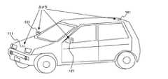
カメラ111は、車両周辺の映像を撮影し、撮影した映像データを送信映像圧縮部112に出力する。図4に第1撮影部110のカメラ111、第2撮影部120のカメラ121、第3撮影部130のカメラ131、第4撮影部140のカメラ141の車両の設置位置の一例を示す。カメラ111は、車両の前方に配置され、車両前方の映像を撮影する。カメラ121は、車両の左側方に配置され、車両左側方の映像を撮影する。カメラ131は、車両の右側方に配置され、車両右側方の映像を撮影する。カメラ141は、車両の後方に配置され、車両後方の映像を撮影する。なお、本実施例では、車両に4つのカメラを搭載しているが、カメラの数は4つに限定されるものではなく、3つでも5つや6つであってもよい。例えば、カメラのレンズを広角レンズとすることで、カメラの設置数を削減することもできる。また、カメラは、最初から車両に搭載されているものであっても連係動作可能であれば問題ない。 The
送信映像圧縮部112は、圧縮率制御部114から指示された圧縮率で、カメラ111によって撮影された映像データを圧縮する。送信映像圧縮部112は、圧縮処理した映像データをネットワークI/F部113に出力する。 The transmission
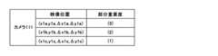
部分重要度パターン記憶部115は、映像データの分割した複数の領域ごとの重要度を表す部分重要度パターンデータを記憶している。図5に部分重要度パターンデータの一例を示す。図5に示すように部分重要度パターンデータは、映像データの分割した領域の位置を示す位置座標と、当該位置座標の映像データの重要度(部分重要度)とを含む。なお、位置座標の例として、例えば、領域の左上座標と、右下座標とを用いることができる。また、重要度とは、生成映像の生成の際に要求される映像データの部分ごとの解像度を反映した情報である。詳細については後述する。 The partial importance
圧縮率制御部114は、図6に示すようにCPU114A、ROM114B、RAM114C、入出力部114D等のハードウェアを備えている。CPU114Aは、ROM114Bに記録されたプログラムに従って動作する。RAM114Cには、CPU114Aが演算に使用するデータ等が格納される。入出力部114Dは、ネットワークを介して制御部230から映像処理装置200の制御部230から送信された指示信号等を入力する。また、CPU114Aから送信映像圧縮部112への圧縮率制御信号を出力する。 The compression rate control unit 114 includes hardware such as a
圧縮率制御部114は、ネットワークI/F部113を介して映像処理装置200の制御部230から生成映像データの生成パターンの指示を受け付ける。制御部230からの指示を受け付けた圧縮率制御部114は、指示された生成パターンに該当する部分重要度パターンデータを部分重要度パターン記憶部115から読み出す。圧縮率制御部114は、読み出した部分重要度パターンデータに従って、カメラ111で撮影された映像データの圧縮率を制御する。なお、生成映像データとは、カメラ111〜141で撮影された映像データに、座標変換等の処理を行って生成される映像データである。生成映像データは、カメラ111〜141で撮影された映像データの使用部分や、座標変換を変更することで複数種類(パターン)生成される。生成映像データの詳細については後述する。 The compression rate control unit 114 receives an instruction for a generation pattern of generated video data from the
圧縮率制御部114の処理について具体的に説明する。
映像データの部分ごとの重要度が、部分重要度パターンデータによって、例えば図7Aに示すように規定されていたとする。なお、図7Aに示す重要度1の部分は、重要度が低い映像データであることを示している。重要度2の部分は、重要度が中位程度の映像データであることを示している。重要度3の部分は、重要度が高い映像データであることを示している。また、重要度0の部分は、重要ではない映像データ、すなわち、生成映像データには使用されない映像データであることを示している。なお、部分重要度パターン記憶部115、125、135、145に記憶している部分重要度パターンデータには、重要度0の映像データの位置座標を示しておかなくてもよい。すなわち、重要度1〜3の映像データの位置座標を規定しておけば、映像データのそれ以外の部分は、すべて重要度0の映像データであると判断できるからである。
圧縮率制御部114は、図7Bに示すように重要度3に設定された重要度の高い部分の映像データに対しては、圧縮率が低くなるように映像データに割り当てる圧縮符号量を制御する。逆に、重要度1に設定された重要度の低い部分の映像データに対しては、圧縮率が高くなるように映像データに割り当てる圧縮符号量を制御する。各カメラ111〜141で撮影された映像データを圧縮して映像処理装置200に送信することで、図7Aと図7Bに示すようにネットワーク150上を送信されるデータ量を削減することができる。The processing of the compression rate control unit 114 will be specifically described.
Assume that the importance of each part of the video data is defined by the partial importance pattern data as shown in FIG. 7A, for example. The portion of
As shown in FIG. 7B, the compression rate control unit 114 controls the amount of compression code assigned to the video data so that the compression rate becomes low for the video data of the high importance level set to the
圧縮率制御部114の処理について、より具体的に説明する。まず、以下の説明で使用する伝送データ量管理単位、圧縮データ量管理単位、圧縮単位について最初に説明しておく。
伝送データ量管理単位とは、伝送路に送信するパケットデータのデータ量を調整する管理単位である。例えば、1フレーム、8フレーム等のフレームを単位に伝送データ量管理単位が設定される。例えば、伝送データ量管理単位当たりの圧縮率が固定の伝送方式の場合、伝送データ量管理単位である1フレーム当たりに使用できる圧縮符号量が一定量に固定されている伝送方式となる。
また、圧縮データ量管理単位とは、圧縮符号量の調整を行う管理単位である。例えば、圧縮率を固定とした場合、この圧縮データ量管理単位で、発生させる圧縮符号の符号量が一定となるように調整を行う。圧縮データ量管理単位は、例えば、8ライン等のラインを単位に設定される。
また、圧縮単位とは、圧縮符号の割り当てを行う単位である。パケットの受信側では、この圧縮単位でデータの復元を行う。The processing of the compression rate control unit 114 will be described more specifically. First, the transmission data amount management unit, the compressed data amount management unit, and the compression unit used in the following description will be described first.
The transmission data amount management unit is a management unit for adjusting the data amount of the packet data transmitted to the transmission path. For example, a transmission data amount management unit is set in units of frames such as 1 frame and 8 frames. For example, in the case of a transmission method in which the compression rate per transmission data amount management unit is fixed, the transmission method is a transmission method in which the compression code amount that can be used per frame, which is the transmission data amount management unit, is fixed to a fixed amount.
The compressed data amount management unit is a management unit for adjusting the compression code amount. For example, when the compression rate is fixed, adjustment is performed so that the code amount of the generated compression code is constant in this compressed data amount management unit. The compressed data amount management unit is set in units of lines such as 8 lines, for example.
The compression unit is a unit for assigning a compression code. On the packet receiving side, data is restored in this compression unit.
伝送データ量管理単位(例えば、1フレーム。以下では、伝送データ量管理単位を1フレームとして説明する)当たりの圧縮率が固定の伝送方式であった場合について説明する。
1フレーム当たりの圧縮率が固定の場合、圧縮率制御部114は、圧縮データ量管理単位(例えば、8ライン。以下、圧縮データ量管理単位を8ラインとして説明する)毎に符号割り当て量を決定する。
まず、圧縮率制御部114は、1フレームに含まれる画素のうち、需要度が0の部分の画素を不要部分として最大圧縮(最小符号量)となるように圧縮符号を割り当てる。
次に、圧縮率制御部114は、伝送データ量管理単位の割り当て可能符号量から不要部分の画素に割り当てた圧縮符号の符号量を除いた残りの符号量を求める。そして、圧縮率制御部114は、求めた残りの圧縮符号の符号量を各圧縮データ量管理単位内の画素ごとの部分重要度の総和の比率に応じて割り当てる。すなわち、重要度1〜3の画素の重要度別の画素数総和を求め、求めた重要度別の画素数総和と、重要度(1〜3)の比率で残符号量を分割し、各画素に割り当てる圧縮符号量を決定する。
なお、各画素に割り当てる符号量を、映像内容の複雑さと映像データの重要度とに基づいて決定することもできる。例えば、圧縮率制御部114は、圧縮データ量管理単位ごとに、この管理単位の映像データの複雑さをまず求める。例えば、映像データに含まれる高周波成分量に応じて映像データの複雑さを判定することができる。ここでは、例えば、5段階で映像データの複雑さを判定するものとする。そして、圧縮率制御部114は、判定した映像データの複雑さを、映像データ自体の重要度により補正して、各画素に割り当てる圧縮符号量を決定する。例えば、映像データの複雑さが複雑であることを示す「5」であっても、映像データの重要度が低ければ、複雑さを表す評価値を低い値に補正する。逆に、映像データの複雑さが複雑ではないことを示す「1」であっても、映像データ自体の重要度が高ければ、複雑さを表す評価値を高い値に補正する。圧縮率制御部114は、補正した複雑さの評価値に基づいて、各画素に割り当てる符号量を決定する。A case will be described in which the compression rate per transmission data amount management unit (for example, one frame. In the following, the transmission data amount management unit is described as one frame) is a fixed transmission method.
When the compression rate per frame is fixed, the compression rate control unit 114 determines the code allocation amount for each compressed data amount management unit (for example, 8 lines. Hereinafter, the compressed data amount management unit will be described as 8 lines). To do.
First, the compression rate control unit 114 assigns a compression code so as to achieve maximum compression (minimum code amount) with a pixel having a degree of demand of 0 as an unnecessary portion among pixels included in one frame.
Next, the compression rate control unit 114 obtains the remaining code amount obtained by subtracting the code amount of the compression code assigned to the unnecessary pixel from the assignable code amount of the transmission data amount management unit. Then, the compression rate control unit 114 assigns the obtained code amount of the remaining compression code according to the ratio of the sum of partial importance levels for each pixel in each compressed data amount management unit. That is, the sum of the number of pixels of
Note that the amount of code to be assigned to each pixel can be determined based on the complexity of the video content and the importance of the video data. For example, for each compressed data amount management unit, the compression rate control unit 114 first determines the complexity of the video data of this management unit. For example, the complexity of the video data can be determined according to the amount of high frequency components included in the video data. Here, for example, the complexity of the video data is determined in five stages. Then, the compression rate control unit 114 corrects the determined complexity of the video data based on the importance of the video data itself, and determines a compression code amount to be assigned to each pixel. For example, even if “5” indicating that the complexity of the video data is complex, if the importance of the video data is low, the evaluation value representing the complexity is corrected to a low value. Conversely, even if “1” indicating that the complexity of the video data is not complicated, if the importance of the video data itself is high, the evaluation value representing the complexity is corrected to a high value. The compression rate control unit 114 determines a code amount to be assigned to each pixel based on the corrected complexity evaluation value.
また、映像データを圧縮する前に、重要度0の映像データの部分は、図8に示すように予め黒画像などの固定値に置換しておくこともできる。黒画像などの固定値に置換しておくことで、置換された部分の映像データが映像データの複雑さの判定によって高圧縮率で処理される。 Further, before compressing the video data, the portion of the video data with the
ネットワークI/F部113は、内部にバッファを備えている。ネットワークI/F部113は、送信映像圧縮部112から出力された圧縮された映像データをバッファに一旦蓄積する。ネットワークI/F部113は、蓄積した映像データを分割してパケットデータに変換し、変換したパケットデータを、送信速度を調整しながらネットワーク150を介して映像処理装置200に送信する。なお、ネットワークI/F部113からネットワーク150に出力されるパケット数は、一定時間内に一定数と規定されている。従って、送信映像圧縮部112による圧縮によって映像データのデータサイズが小さくなると、1パケットデータのデータサイズもそれに応じて小さくなる。ネットワークI/F部113で生成されたパケットデータは、ネットワーク150により伝送され、映像処理装置200に送られる。 The network I /
図2に戻って、映像処理装置200について説明する。
ネットワークI/F部210は、第1撮影部110〜第4撮影部140から送信されたパケットデータを受信する。ネットワークI/F部210もバッファを備え、受信したパケットデータを一旦蓄積する。ネットワークI/F部210は、受信したパケットデータを復号処理して映像データに戻し、映像データにブランキングデータを付加して映像生成部220に出力する。また、ネットワークI/F部210は、第1撮影部110〜第4撮影部140からパケットデータを受信すると、受信したパケットデータを映像データに戻すことなく、データ列のまま映像生成部220に出力してもよい。この場合、映像生成部220でデータ列から映像データに変換することになる。
なお、撮影装置100側で高圧縮率の圧縮符号を割り当てた重要度0の映像データは、映像処理装置200側には特定色ないしは特定のパターンデータとして受信されるが、生成映像データの生成には使用されない部分なので、生成映像データに影響を及ぼすことはない。Returning to FIG. 2, the
The network I /
Note that video data of
映像生成部220は、第1撮影部110〜第4撮影部140から送信された映像データを座標変換して、生成映像データを生成する。記憶部240には、後述する生成映像変換パターンデータが記憶されている。映像生成部220は、制御部230から指示された生成映像データを生成するための生成映像変換パターンデータを記憶部240から取得する。映像生成部220は取得した生成映像変換パターンデータに従って、第1撮影部110〜第4撮影部140から送信された映像データを座標変換し、生成映像データを生成する。 The
送信部250は、映像生成部220で生成された生成映像データを表示装置320に送信する。 The
次に、制御部230について説明する。図9には、制御部230のハードウェア構成の一例を示す。制御部230は、ハードウェアとしてCPU(Central Processing Unit)231、ROM(Read Only Memory)232、RAM(Random Access Memory)233、入出力部234を備えている。
ROM232には、CPU231が制御に使用するプログラムが記録されている。CPU231は、ROM232に記録されたプログラムを読み込んで、読み込んだプログラムに従った処理を行う。また、RAM233には、CPU231が演算に使用するデータや、演算結果のデータが記憶される。入出力部234は、ユーザによって操作部310から入力された操作入力を受け付け、CPU231に出力する。また、入出力部234は、CPU231から出力される指示信号をネットワークI/F部210に出力する。ネットワークI/F部210は、入出力部234から出力された指示信号をネットワーク150を介して第1撮影部110〜第4撮影部140に送信する。Next, the
The
制御部230は、部分重要度パターンデータを生成映像データのパターンごとに複数生成する。部分重要度パターンデータは、第1撮影部110〜第4撮影部140ごとに生成される。制御部230は、生成した部分重要度パターンデータをネットワーク150を介して、撮影装置100に送信する。第1撮影部110〜第4撮影部140は、制御部230から送信された、該当する部分重要度パターンデータを部分重要度パターン記憶部115、125、135、145に記憶する。なお、部分重要度パターンデータは、生成映像データのパターン毎のデータを全て部分重要度パターン記憶部に記憶させておいても良いし、生成映像データのパターンの切り替えの際に対応する部分重要度パターンデータを送信して部分重要度パターン記憶部に記憶するようにしても良い。
また、制御部230は、後述する生成映像変換パターンデータを生成し、生成した生成映像変換パターンデータを記憶部240に記憶する。この生成映像変換パターンデータも生成映像データのパターンごとに複数生成される。The
In addition, the
操作部310は、操作者からの操作入力を受け付ける。表示装置320は、映像処理装置200から送信された生成映像データを受信する受信部321と、受信した生成映像データを表示する表示部322とを備えている。映像処理装置200で生成された生成映像データは送信部250によって表示装置320に送信される。表示装置320は、送信部250から送信された生成映像を受信部321で受信して、表示部322に表示させる。操作者は、表示部322に表示させる生成映像のパターンを切り替える操作を操作部310から行う。表示部322に表示される生成映像の例(パターン)を図10A、図10B、図11A、図11B、図12A、図12Bに示す。 The
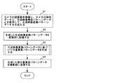
次に、図13、図14に示すフローチャートを参照しながら制御部230が部分重要度パターンデータと、生成映像変換パターンデータとを生成する手順を説明する。
まず、事前の準備として、カメラ111、121、131、141を車両に設置し、各カメラ111、121、131、141の位置座標と取り付け角度とを算出する。位置座標と取り付け角度との算出は、作業員が機器を使用して行う。図15A、15Bに示すように車両の中心を原点として、車両の幅方向をX軸、車両の前後軸方向をY軸、鉛直方向をZ軸とする。図15Aには、車両を鉛直方向(Z軸方向)から見た座標系を示し、図15Bには、車両を幅方向(X軸方向)から見た座標系を示す。また、カメラの取付角度には、ヨー角、俯角、ロール角が含まれる。ヨー角とは、図16に示すように鉛直軸周りの回転角度をいう。また、カメラの光軸周りの回転角度をロール角といい、カメラの上下方向の傾きをピッチ角という。なお、以下では、カメラの位置座標と取り付け角度とを総称してカメラの設置条件情報と呼ぶ。カメラの設置条件情報は、操作部310から入力され、制御部230の制御に従って、記憶部240に記憶される。Next, a procedure in which the
First, as a preliminary preparation, the
事前に記憶部240に記憶させるデータには、カメラの設置条件情報の他に、カメラ111、121、131、141の特性データと、生成映像構成パターンデータとが含まれる。特性データとは、各カメラ111、121、131、141の水平、垂直方向の画素数及び画角(各カメラ111、121、131、141の視野角)とレンズディストーションデータ(レンズの歪曲収差データ)である。また、生成映像構成パターンデータには、映像投影面の形状データと、視点ベクトルのデータと、映像の表示範囲を示すデータ等が含まれる。映像投影面の形状データは、図17に示すように、各カメラ111、121、131、141で撮影された複数の映像データから生成映像データを生成するために、複数の映像データを投影させる投影面の形状データである。また、視点ベクトルのデータとは、映像データを投影させた映像投影面をどこから見た生成映像データとするかを規定するデータである。この映像投影面の形状データと、視点ベクトルとにより各カメラ111〜141によって撮影された映像の部分ごとの倍率が変化する。また、映像の表示範囲を示すデータは、図17に示すように生成映像データとして表示させる範囲を示すデータである。 The data stored in advance in the
制御部230は、記憶部240に記憶されたカメラの設置条件情報と、カメラの特性データと、生成映像構成パターンデータとを使用して生成映像変換パターンデータを生成する(ステップS1)。生成映像変換パターンデータは、各カメラ111、121、131、141の映像データを生成映像データに変換するための座標変換データである。生成映像変換パターンデータは、例えば、図18Aに示すようにポリゴン番号と、ポリゴン番号が示すポリゴンの各頂点の番号と、頂点番号が示す各頂点の座標変換前の座標値情報と、頂点番号が示す各頂点の座標変換後の生成映像データ上での座標値データとを含む。なお、ポリゴンとは、カメラの映像データから生成映像データに座標変換するときの座標変換の処理単位となる区画であり、ポリゴン番号は、各ポリゴンを識別する識別番号である。また、生成映像変換パターンデータは、図18Bに示すデータ形式であってもよい。図18Bに示す生成映像変換パターンデータは、ポリゴン番号と、ポリゴン番号が示すポリゴンの頂点番号と、頂点番号が示す頂点の座標変換前の映像データ上の座標値のデータと、映像投影面上での座標値のデータと、視点ベクトルデータとを含む。制御部230は、生成した生成映像変換パターンデータを記憶部240に記憶する(ステップS2) The
次に、制御部230は、生成映像変換パターンデータを用いて部分重要度パターンデータを生成する(ステップS3)。生成映像変換パターンデータから部分重要度パターンデータを生成する手順については、図14に示すフローチャートを参照しながら後述する。 Next, the
次に、制御部230は、生成した各部分重要度パターンデータを、対応する撮影部(第1撮影部110〜第4撮影部140)に送信する(ステップS4)。第1撮影部110〜第4撮影部140は、制御部230から送信された部分重要度パターンデータを各部分重要度パターン記憶部115、125、135、145に記憶する。 Next, the
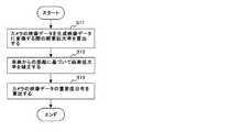
次に、図14に示すフローチャートを参照しながら制御部230が生成映像変換パターンデータから部分重要度パターンデータを生成する手順について説明する。
まず、制御部230は、生成映像変換パターンデータを参照して、各カメラ111、121、131、141の映像データから生成映像データに使用される使用範囲を算出する。さらに、制御部230は、使用範囲の映像データの各画素の座標変換による拡大率(縮小を含む:以下、画素拡大率という)を算出する(ステップS11)。さらに、制御部230は、算出した各画素の画素拡大率に基づいて画素拡大率の分布を算出する。制御部230は、使用範囲の映像データの各画素が座標変換に伴って拡大(又は縮小される)画素拡大率を算出する。画素拡大率の算出は、X軸方向、Y軸方向でそれぞれ算出してもよいし、各画素の座標変換前と変換後の面積比で求めてもよい。Next, a procedure in which the
First, the
次に、制御部230は、車両からの距離に基づいて画素拡大率を補正する範囲を求め、画素拡大率を補正する(ステップS12)。例えば、運転支援に効果のない遠方や空の部分は、運転支援のための生成映像データには必要のない部分と判定し、制御部230は対象外のデータ、又は重要度を下げる対象のデータに設定する。図19Aに示す例では、Z軸(鉛直)方向の座標値が一定値Z1よりも大きい生成映像データの画素の画素拡大率を所定値に修正したり、画素拡大率を所定値下げる補正を行う。また、図19Bに示す例では、X軸方向、Y軸方向について、自車両の近傍の一定範囲内だけが運転支援に重要な範囲と判定する。例えば、制御部230は、図19Bに示すように車両の全幅、全長(X2、Y4)に一定値を加算した範囲(X2+X3、Y4+Y5)よりも外側の画素の画素拡大率を所定値に修正したり、画素拡大率を所定値下げる補正を行う。 Next, the
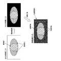
次に、制御部230は、ステップS12で補正した各画素の画素拡大率に対してクラスタリング(又は正規化)等の処理を行い、画素拡大率をクラス分けする。制御部230は、クラス分けした画素拡大率に基づいて重要度分布を求める(ステップS13)。例えば、画素拡大率が5以上の画素の分布、画素拡大率が2以上5未満の画素の分布、画素拡大率が0よりも大きく2未満の画素の分布、画素拡大率が0の画素の分布をそれぞれ求める。そして、画素拡大率が5以上の画素の分布を重要度高の画素分布とする。また、画素拡大率が2以上5未満の画素の分布を重要度中の画素分布とする。また、画素拡大率が0よりも大きく2未満の画素の分布を重要度低の画素分布とする。また、画素拡大率が0の画素の分布を重要度0(生成映像に使用しない)の画素分布とする。画素拡大率の大きい画素は、生成映像データに変換したときの表示面積が広いため、重要度の高いデータであると判断できる。また、画素拡大率の低い画素は、生成映像データに変換したときの表示面積が狭いため、重要度の低いデータであると判断できる。
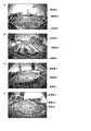
図20Aにカメラ111で撮影された車両前方の映像データの重要度分布を示す。同様に、図20Bに、カメラ121で撮影された車両左側方の映像データの重要度分布を示す。図20Cに、カメラ131で撮影された車両右方の映像データの重要度分布を示す。図20Dに、カメラ141で撮影された車両後方の映像データの重要度分布を示す。図21に、生成された第1撮影部110〜第4撮影部140の部分重要度パターンデータの一例を示す。Next, the
FIG. 20A shows the importance distribution of the video data in front of the vehicle photographed by the
制御部230は、以上の処理を行い、部分重要度パターンデータと、生成映像変換パターンデータとを生成する。制御部230は、各カメラの映像データごとに生成した部分重要度パターンデータを、第1撮影部110〜第4撮影部140にそれぞれ送信する。第1撮影部110〜第4撮影部140の部分重要度パターン記憶部115、125、135、145には、生成映像データのパターンごとに部分重要度パターンデータが記憶される。 The
次に、図22、図23に示すフローチャートを参照しながら、映像処理システム1の動作手順を説明する。
まず、制御部230は、操作部310から生成映像の変更指示が入力されたか否かを判定する(ステップS21)。生成映像の変更指示が入力された場合には(ステップS21/YES)、制御部230は、変更指示を撮影装置100に通知する。通知を受けた第1撮影部110〜第4撮影部140は、生成映像の変更指示をメモリに記録する(ステップS22)。Next, the operation procedure of the
First, the
次に、カメラ111〜141で映像を撮影し、映像データを入力すると(ステップS23/YES)、圧縮率制御部114〜144は、制御部230から指示された生成映像を生成するための部分重要度パターンデータを取得する。圧縮率制御部114〜144は、取得した部分重要度パターンデータを参照して、カメラ111〜141で撮影された映像データの圧縮率を制御する(ステップS24)。この際、圧縮率制御部114〜141は、部分重要度パターンデータとして記録された重要度に応じて映像データの部分ごとの圧縮率を変更する。送信映像圧縮部112〜142で圧縮された映像データは、ネットワークI/F部113〜143にそれぞれ出力される。ネットワークI/F部113〜143は、圧縮された1フレームの映像データのデータ量に応じたサイズのパケットデータを生成し、映像処理装置200に送信する(ステップS25)。 Next, when images are captured by the
次に、図23に示すフローチャートを参照しながら映像処理装置200の処理手順を説明する。
映像処理装置200は、ネットワーク150を介して第1撮影部110〜第4撮影部140から送信されたパケットデータをネットワークI/F部210で受信する。ネットワークI/F部210は、パケットデータを入力すると(ステップS31/YES)、入力したパケットデータを復号して映像データに変換する(ステップS32)。ネットワークI/F部210は、復号した映像データにブランキングデータを付加して映像生成部220に出力する。映像生成部220は、ネットワークI/F部210から映像データを入力すると、記憶部240に記憶した生成映像変換パターンデータを参照して、複数の映像データから生成映像データに変換する(ステップS33)。Next, the processing procedure of the
The
このように本実施例は、部分重要度パターンデータとして記録された重要度に応じて映像データの部分ごとの圧縮率を変更し、圧縮したデータを映像処理装置200に送信している。従って、撮影装置から送信されるデータ量の削減と、高品質な生成映像の生成とを両立させることができる。 As described above, in this embodiment, the compression rate for each part of the video data is changed according to the importance recorded as the partial importance pattern data, and the compressed data is transmitted to the
上述した実施例は、本発明の好適な実施の例である。但し、これに限定されるものではなく、本発明の要旨を逸脱しない範囲内において種々変形実施可能である。 The embodiment described above is a preferred embodiment of the present invention. However, the present invention is not limited to this, and various modifications can be made without departing from the scope of the present invention.
1 映像処理システム
100 撮影装置
110 第1撮影部
111、121、131、141 カメラ
112、122、132、142 送信映像圧縮部
113、123、133、143 ネットワークI/F部
114、124、134、144 圧縮率制御部
115、125、135、145 部分重要度パターン記憶部
120 第2撮影部
130 第3撮影部
140 第4撮影部
200 映像処理装置
210 ネットワークI/F部
220 映像生成部
230 制御部
240 記憶部
250 送信部
310 操作部
320 表示装置DESCRIPTION OF
Claims (7)
Translated fromJapanese前記複数の撮影装置は、それぞれ、映像データの分割した複数の領域を識別する領域情報と、生成映像データの生成の際に前記映像データの各領域に要求される解像度に基づいて前記各領域ごとに算出された重要度とを記憶した記憶部と、
前記重要度を参照して、撮影された映像データの各領域を重要度に応じた圧縮率で圧縮する映像圧縮部と、
前記圧縮された映像データを前記車内伝送路経由で前記映像処理装置に送信する送信部とを備え、
前記映像処理装置は、
前記複数の撮影装置から送信される、前記圧縮された映像データを入力する入力部と、
入力した複数の圧縮された映像データに基づいて、前記表示装置に表示する映像データを生成する映像生成部と、
生成した映像データを前記表示装置に送信する送信部とを備え、
前記表示装置は、
前記映像処理装置から送信された前記生成映像データを受信する受信部と、
受信した生成映像データを表示する表示部とを備えた、
ことを特徴とする映像処理システム。A display device capable of displaying video data, a plurality of photographing devices capable of photographing the periphery of the vehicle, and a plurality of types of generated video data from the plurality of photographed video data in cooperation with the plurality of photographing devices via an in-vehicle transmission path A video processing system comprising a video processing device for generating
Each of the plurality of imaging devices is configured to determine each region based on region information for identifying a plurality of regions obtained by dividing the video data and a resolution required for each region of the video data when generating the generated video data. A storage unit storing the importance calculated in
With reference to the importance, a video compression unit that compresses each area of the captured video data at a compression rate according to the importance,
A transmission unit that transmits the compressed video data to the video processing device via the in-vehicle transmission path,
The video processing device includes:
An input unit for inputting the compressed video data transmitted from the plurality of photographing devices;
A video generation unit that generates video data to be displayed on the display device based on a plurality of compressed video data input;
A transmission unit that transmits the generated video data to the display device,
The display device
A receiving unit for receiving the generated video data transmitted from the video processing device;
A display unit for displaying the received generated video data;
A video processing system characterized by that.
生成映像データを生成するための映像データを撮影する撮影部と、
映像データの分割した複数の領域を識別する領域情報と、生成映像データの生成の際に前記映像データの各領域に要求される解像度に基づいて前記各領域ごとに算出された重要度とを記憶した記憶部と、
前記重要度を参照して、撮影された映像データの各領域を重要度に応じた圧縮率で圧縮する映像圧縮部と、
前記圧縮された映像データを前記車内伝送路経由で前記映像処理装置に送信する送信部とを備えた、
ことを特徴とする撮影装置。Video processing that generates multiple types of generated video data from multiple captured video data in conjunction with a display device capable of displaying video data, an imaging device capable of capturing the periphery of the vehicle, and an imaging device via an in-vehicle transmission path An imaging device that can be used in a video processing system comprising the device,
A photographing unit for photographing video data for generating generated video data;
Stores area information for identifying a plurality of divided areas of video data and importance calculated for each area based on the resolution required for each area of the video data when generating generated video data Storage unit
With reference to the importance, a video compression unit that compresses each area of the captured video data at a compression rate according to the importance,
A transmission unit that transmits the compressed video data to the video processing device via the in-vehicle transmission path,
An imaging apparatus characterized by that.
前記複数の撮影装置において、
記憶部に記憶された、映像データの分割した複数の領域を識別する領域情報と、生成映像データの生成の際に前記映像データの各領域に要求される解像度に基づいて前記各領域ごとに算出された重要度とを参照して、撮影された映像データの各領域を重要度に応じた圧縮率で圧縮するステップと、
前記圧縮された映像データを前記車内伝送路経由で前記映像処理装置に送信するステップとを実行し、
前記映像処理装置において、
前記複数の撮影装置から送信される、前記圧縮された映像データを入力するステップと、
入力した複数の圧縮された映像データに基づいて、前記表示装置に表示する映像データを生成するステップと、
生成した映像データを前記表示装置に送信するステップとを実行し、
前記表示装置において、
前記映像処理装置から送信された前記生成映像データを受信するステップと、
受信した生成映像データを表示部に表示するステップとを実行することを特徴とする映像処理方法。A display device capable of displaying video data, a plurality of photographing devices capable of photographing the periphery of the vehicle, and a plurality of types of generated video data from the plurality of photographed video data in cooperation with the plurality of photographing devices via an in-vehicle transmission path A video processing method executed by a video processing system including a video processing device for generating
In the plurality of photographing devices,
Calculated for each area based on the area information stored in the storage unit for identifying a plurality of divided areas of the video data and the resolution required for each area of the video data when generating the generated video data Compressing each area of the captured video data with a compression rate corresponding to the importance, with reference to the importance obtained,
Transmitting the compressed video data to the video processing device via the in-vehicle transmission path,
In the video processing device,
Inputting the compressed video data transmitted from the plurality of imaging devices;
Generating video data to be displayed on the display device based on a plurality of input compressed video data;
Transmitting the generated video data to the display device;
In the display device,
Receiving the generated video data transmitted from the video processing device;
And a step of displaying the received generated video data on a display unit.
Priority Applications (2)
| Application Number | Priority Date | Filing Date | Title |
|---|---|---|---|
| JP2009113931AJP2010263500A (en) | 2009-05-08 | 2009-05-08 | Video processing system, photographing apparatus, and video processing method |
| US12/774,920US20100283589A1 (en) | 2009-05-08 | 2010-05-06 | Image processing system, image capture device and method thereof |
Applications Claiming Priority (1)
| Application Number | Priority Date | Filing Date | Title |
|---|---|---|---|
| JP2009113931AJP2010263500A (en) | 2009-05-08 | 2009-05-08 | Video processing system, photographing apparatus, and video processing method |
Publications (1)
| Publication Number | Publication Date |
|---|---|
| JP2010263500Atrue JP2010263500A (en) | 2010-11-18 |
Family
ID=43062014
Family Applications (1)
| Application Number | Title | Priority Date | Filing Date |
|---|---|---|---|
| JP2009113931AWithdrawnJP2010263500A (en) | 2009-05-08 | 2009-05-08 | Video processing system, photographing apparatus, and video processing method |
Country Status (2)
| Country | Link |
|---|---|
| US (1) | US20100283589A1 (en) |
| JP (1) | JP2010263500A (en) |
Cited By (5)
| Publication number | Priority date | Publication date | Assignee | Title |
|---|---|---|---|---|
| KR20150067707A (en)* | 2013-12-10 | 2015-06-18 | 삼성테크윈 주식회사 | Image processing apparatus, image processing method, and photographing apparatus |
| WO2019049548A1 (en)* | 2017-09-05 | 2019-03-14 | 株式会社デンソー | Image processing device |
| WO2020230385A1 (en) | 2019-05-15 | 2020-11-19 | Kddi株式会社 | Program, device, and method for generating meaningful video stream from original video stream |
| JP2020198116A (en)* | 2016-05-25 | 2020-12-10 | パナソニックIpマネジメント株式会社 | Object detection device, program and recording medium |
| US11881104B2 (en) | 2016-05-25 | 2024-01-23 | Panasonic Intellectual Property Management Co., Ltd. | Object detection apparatus, and storage medium |
Families Citing this family (7)
| Publication number | Priority date | Publication date | Assignee | Title |
|---|---|---|---|---|
| JP5967577B2 (en)* | 2012-10-18 | 2016-08-10 | パナソニックIpマネジメント株式会社 | Co-clustering apparatus, co-clustering method, program, and integrated circuit |
| KR101879855B1 (en)* | 2012-12-22 | 2018-07-19 | (주)지오투정보기술 | Digital map generating system for performing spatial modelling through a distortion correction of image |
| GB2528246A (en)* | 2014-07-07 | 2016-01-20 | Roke Manor Research | Region based image compression on a moving platform |
| US10091391B2 (en)* | 2015-11-10 | 2018-10-02 | Bidirectional Display, Inc. | System and method for constructing document image from snapshots taken by image sensor panel |
| KR102436954B1 (en)* | 2015-11-24 | 2022-08-29 | 삼성전자주식회사 | Image photographing apparatus and method of controlling thereof |
| US12164594B2 (en) | 2021-06-04 | 2024-12-10 | Toyota Motor Engineering & Manufacturing North America, Inc. | Systems and methods for scheduling environment perception-based data offloading for numerous connected vehicles |
| JP2023014750A (en)* | 2021-07-19 | 2023-01-31 | ウーブン・プラネット・ホールディングス株式会社 | Mobile control system, mobile control method, and mobile remote assistance system |
Family Cites Families (6)
| Publication number | Priority date | Publication date | Assignee | Title |
|---|---|---|---|---|
| US6891563B2 (en)* | 1996-05-22 | 2005-05-10 | Donnelly Corporation | Vehicular vision system |
| EP1408693A1 (en)* | 1998-04-07 | 2004-04-14 | Matsushita Electric Industrial Co., Ltd. | On-vehicle image display apparatus, image transmission system, image transmission apparatus, and image capture apparatus |
| JP3269056B2 (en)* | 2000-07-04 | 2002-03-25 | 松下電器産業株式会社 | Monitoring system |
| US7016532B2 (en)* | 2000-11-06 | 2006-03-21 | Evryx Technologies | Image capture and identification system and process |
| JP3938532B2 (en)* | 2002-09-05 | 2007-06-27 | 本田技研工業株式会社 | Vehicle control apparatus, program and method |
| US20080036864A1 (en)* | 2006-08-09 | 2008-02-14 | Mccubbrey David | System and method for capturing and transmitting image data streams |
- 2009
- 2009-05-08JPJP2009113931Apatent/JP2010263500A/ennot_activeWithdrawn
- 2010
- 2010-05-06USUS12/774,920patent/US20100283589A1/ennot_activeAbandoned
Cited By (11)
| Publication number | Priority date | Publication date | Assignee | Title |
|---|---|---|---|---|
| KR20150067707A (en)* | 2013-12-10 | 2015-06-18 | 삼성테크윈 주식회사 | Image processing apparatus, image processing method, and photographing apparatus |
| KR102138331B1 (en)* | 2013-12-10 | 2020-07-27 | 한화테크윈 주식회사 | Image processing apparatus, image processing method, and photographing apparatus |
| JP2020198116A (en)* | 2016-05-25 | 2020-12-10 | パナソニックIpマネジメント株式会社 | Object detection device, program and recording medium |
| US11881104B2 (en) | 2016-05-25 | 2024-01-23 | Panasonic Intellectual Property Management Co., Ltd. | Object detection apparatus, and storage medium |
| WO2019049548A1 (en)* | 2017-09-05 | 2019-03-14 | 株式会社デンソー | Image processing device |
| JP2019047401A (en)* | 2017-09-05 | 2019-03-22 | 株式会社デンソー | Image processing apparatus |
| US11257193B2 (en) | 2017-09-05 | 2022-02-22 | Denso Corporation | Image processing apparatus |
| WO2020230385A1 (en) | 2019-05-15 | 2020-11-19 | Kddi株式会社 | Program, device, and method for generating meaningful video stream from original video stream |
| JP2020188368A (en)* | 2019-05-15 | 2020-11-19 | Kddi株式会社 | Program, device and method for generating significant video stream from original video stream |
| JP6995083B2 (en) | 2019-05-15 | 2022-01-14 | Kddi株式会社 | Programs, devices and methods to generate a significant video stream from the original video stream |
| US12113957B2 (en) | 2019-05-15 | 2024-10-08 | Kddi Corporation | Program, device, and method for generating significant video stream from original video stream |
Also Published As
| Publication number | Publication date |
|---|---|
| US20100283589A1 (en) | 2010-11-11 |
Similar Documents
| Publication | Publication Date | Title |
|---|---|---|
| JP2010263500A (en) | Video processing system, photographing apparatus, and video processing method | |
| US8305424B2 (en) | System, apparatus and method for panorama image display | |
| US7450165B2 (en) | Multiple-view processing in wide-angle video camera | |
| US9253411B2 (en) | Image processing apparatus, image processing method and image communication system | |
| CN108028889B (en) | Image processing apparatus, image processing method, program, and camera system | |
| US7932934B2 (en) | Image processing method and imaging apparatus using the same | |
| WO2021199184A1 (en) | Image display system, image processing device, image display method, and computer program | |
| JP6533761B2 (en) | INFORMATION PROCESSING APPARATUS, INFORMATION PROCESSING SYSTEM, AND INFORMATION PROCESSING METHOD | |
| JP2011097521A (en) | Moving image processing program, device, and method, and imaging apparatus mounting the moving image processing device | |
| KR20170026167A (en) | Method of pre-processing digital images, and digital image pre-processing system | |
| JP2004272578A (en) | Image pickup unit and distortion correction method | |
| JP2010263499A (en) | Video processing system and video processing method | |
| JP5872171B2 (en) | Camera system | |
| JP2010219872A (en) | Camera apparatus, display, system and method for processing image | |
| US12425737B2 (en) | Image capturing apparatus, information processing apparatus, control method, and storage medium | |
| JP4680087B2 (en) | Image transmission device | |
| JP6563694B2 (en) | Image processing apparatus, image processing system, image composition apparatus, image processing method, and program | |
| JP2020145651A (en) | Information processor, system, information processing method, and program | |
| EP4258661A1 (en) | Encoding/decoding method, electronic device, communication system, and storage medium | |
| JP6639205B2 (en) | Transmission device, transmission method, and program | |
| JP2019009507A (en) | Image processing apparatus, control method therefor, imaging apparatus, and monitoring system | |
| JP5838775B2 (en) | Image processing method, image processing system, and image processing program | |
| JP2000209569A (en) | Remote monitor, remote monitoring method and remote monitoring system | |
| JP2010171876A (en) | Communication device and communication system | |
| CN113301308A (en) | Video monitoring device for safety monitoring |
Legal Events
| Date | Code | Title | Description |
|---|---|---|---|
| A300 | Application deemed to be withdrawn because no request for examination was validly filed | Free format text:JAPANESE INTERMEDIATE CODE: A300 Effective date:20120807 |