JP2010257046A - Proximity detector - Google Patents
Proximity detectorDownload PDFInfo
- Publication number
- JP2010257046A JP2010257046AJP2009103981AJP2009103981AJP2010257046AJP 2010257046 AJP2010257046 AJP 2010257046AJP 2009103981 AJP2009103981 AJP 2009103981AJP 2009103981 AJP2009103981 AJP 2009103981AJP 2010257046 AJP2010257046 AJP 2010257046A
- Authority
- JP
- Japan
- Prior art keywords
- proximity
- detection
- baseline
- finger
- value
- Prior art date
- Legal status (The legal status is an assumption and is not a legal conclusion. Google has not performed a legal analysis and makes no representation as to the accuracy of the status listed.)
- Pending
Links
Images


Landscapes
- Position Input By Displaying (AREA)
- Switches That Are Operated By Magnetic Or Electric Fields (AREA)
Abstract
Translated fromJapaneseDescription
Translated fromJapaneseこの発明は、タッチパネルに配置されている複数の検知電極の静電容量を検出して、ユーザがタッチパネルに接触している位置又は近接している位置を特定する近接検知装置に関するものである。 The present invention relates to a proximity detection device that detects capacitances of a plurality of detection electrodes arranged on a touch panel and identifies a position where a user is in contact with or close to the touch panel.
ユーザの意思を直接的に入力する手段として、ユーザがパネルや情報表示面に配置されている操作キーに触れると、その接触位置を検出するタッチセンサが有効なことが良く知られている。従来、実用に供されている代表的なタッチセンサとして、下記(a)〜(c)に示すものがある。 As a means for directly inputting a user's intention, it is well known that a touch sensor that detects a contact position when a user touches an operation key arranged on a panel or an information display surface is effective. Conventionally, typical touch sensors that have been put to practical use include those shown in the following (a) to (c).
(a)2枚の導電シートが直接接触しないように重ね合わされている電気抵抗変化検出型タッチセンサ。ユーザが導電シートの任意の位置を押下すると、押下された位置で2枚の導電シートが導通するので、タッチセンサはその導通箇所の座標を検出する。
(b)情報表示面に近い空間に光線ビームが張られているビーム遮断型タッチセンサ。ユーザが情報表示面に触れようとして指を近づけると、ユーザが触れようとしている位置に張られたビームが遮断されるので、タッチセンサはその遮断箇所の座標を検出する。
(c)透明、不透明又は半透明の電極の静電容量を検出する静電センサ。ユーザの指又は誘電体が電極に接触又は近接すると静電容量が変化するので、タッチセンサは容量変化した電極の座標を検出する。(A) An electrical resistance change detection type touch sensor in which two conductive sheets are superposed so as not to be in direct contact with each other. When the user presses an arbitrary position on the conductive sheet, the two conductive sheets are brought into conduction at the pressed position, so that the touch sensor detects the coordinates of the conduction portion.
(B) A beam blocking touch sensor in which a light beam is stretched in a space near the information display surface. When the user approaches his / her finger to touch the information display surface, the beam stretched at the position where the user is going to touch is blocked, and the touch sensor detects the coordinates of the blocking location.
(C) An electrostatic sensor that detects the capacitance of a transparent, opaque, or translucent electrode. When the user's finger or dielectric touches or approaches the electrode, the capacitance changes, so the touch sensor detects the coordinates of the electrode whose capacitance has changed.
上記(a)の電気抵抗変化検出型タッチセンサは、ユーザが導電シートに接触しない限り、座標を検出することができず、導電シートに対するユーザの近接及びその近接座標を検出することができないという欠点がある。
上記(b)のビーム遮断型タッチセンサは、ユーザが情報表示面に触れなくても、情報表示面に対するユーザの近接及びその近接座標を検出することができる。しかし、ユーザが指示する位置の座標を確定する時点がフィードバックされないため、入力時点の不確定性による不安が大きくなることがあるという欠点がある。The electrical resistance change detection type touch sensor (a) cannot detect coordinates unless the user touches the conductive sheet, and cannot detect the proximity of the user to the conductive sheet and its proximity coordinates. There is.
The beam blocking touch sensor (b) can detect the proximity of the user to the information display surface and its proximity coordinates without the user touching the information display surface. However, since the time when the coordinates of the position designated by the user are determined is not fed back, there is a drawback that anxiety due to uncertainty at the input time may increase.
上記(a)及び(b)に対し、上記(c)の静電センサは、電極に対するユーザの接触及び近接の両方を検出することが可能であり、電気抵抗変化検出型タッチセンサ及びビーム遮断型タッチセンサの欠点を解消することができる。
しかしながら、静電センサは温度変化、環境変動(周辺機器の影響等)等により、電極から出力される静電容量値が変動するため、絶対的な静電容量値を用いて指の近接及び接触を検出することは困難であった。
そこで、例えば特許文献1に、ユーザの指及び誘電体が電極に触れていない状態での静電容量値を基準容量(ベースライン値)とし、指等による入力を検出する際には電極から出力された静電容量値とベースライン値の差分値を用いて、指の近接及び接触状態を検知する方法(感度キャリブレーション)が開示されている。In contrast to the above (a) and (b), the electrostatic sensor of (c) can detect both the contact and proximity of the user to the electrode, and the electrical resistance change detection type touch sensor and the beam blocking type. The drawbacks of touch sensors can be eliminated.
However, the capacitance value output from the electrode fluctuates due to temperature changes, environmental fluctuations (such as the influence of peripheral devices), etc., so the proximity and contact of the finger using absolute capacitance values. It was difficult to detect.
Therefore, for example, in
従来の近接検知装置は以上のように構成されているので、指が近接した状態で感度キャリブレーションを行った場合には、指が近接した状態での静電容量値がベースライン値となってしまい、実際より大きい値でキャリブレーションされてしまう。この結果、入力検出時の静電容量値とベースライン値の差分が小さくなり、場合によっては指の接触を検出できないといった課題があった。 Since the conventional proximity detection device is configured as described above, when sensitivity calibration is performed with the finger in proximity, the capacitance value in the state in which the finger is in proximity becomes the baseline value. Therefore, calibration is performed with a value larger than the actual value. As a result, there is a problem that the difference between the capacitance value and the baseline value at the time of input detection becomes small, and in some cases, finger contact cannot be detected.
接触のみを検出する装置であれば、指が電極に直接接触した場合と空気層を介して近接した場合とでは非誘電率の差異による大きな静電容量変化が生じるため、ベースライン値が多少高くなっても指の接触検出が可能になることもある。しかし、指の接触のみでなく、指の近接も検出する装置では、指が空気層を介して電極に接近した場合と、接近状態から更に電極に近づいて近接した場合とを判別する必要があり、指が接近した状態で感度キャリブレーションが行われた場合にはその影響がベースライン値に大きく反映されてしまい、結果的に指の近接検知ができないといった課題があった。 In the case of a device that only detects contact, the baseline value is slightly higher because a large capacitance change occurs due to the difference in non-dielectric constant between when the finger is in direct contact with the electrode and when it is close to the air layer. In some cases, finger contact detection may be possible. However, in a device that detects not only finger contact but also finger proximity, it is necessary to distinguish between when the finger approaches the electrode through the air layer and when the finger approaches the electrode further from the approaching state. When sensitivity calibration is performed with the finger approaching, the influence is greatly reflected in the baseline value, resulting in a problem that proximity detection of the finger cannot be performed.
この発明は、上記のような課題を解決するためになされたもので、指の近接及び接触を検出可能な手段を設けて、電極に指が近接していない状態でキャリブレーションを行うことにより、指の近接時に誤ったキャリブレーションが行われることを防いで、安定した指の接触検知を行うことを目的とする。 The present invention was made to solve the above-described problems.By providing a means capable of detecting the proximity and contact of a finger and performing calibration in a state where the finger is not in proximity to the electrode, An object of the present invention is to perform stable finger contact detection by preventing erroneous calibration when a finger is approaching.
また、指が近接していない状態の電極間の静電容量分布に基づいて、電極に指が接近していない状態においてのみキャリブレーションを行うことにより、指の接近時に誤ったキャリブレーションが行われることを防いで、安定した指の近接及び接触検知を行うことを目的とする。 In addition, based on the capacitance distribution between the electrodes when the finger is not in proximity, calibration is performed only when the finger is not approaching the electrode, so that erroneous calibration is performed when the finger is approaching The object is to perform stable finger proximity and contact detection.
この発明に係る近接検知装置は、検知対象物との距離に応じて静電容量が変化する複数の検知電極と、検知電極と検知対象物間の静電容量値を検出する静電容量検出部と、静電容量検出部が検出した静電容量値とベースライン値とを用いて、検知対象物の検知電極への近接又は接触状態を判別する近接・接触検出部と、近接・接触検出部が用いるベースライン値を格納しておくベースライン格納部と、静電容量検出部が検出した静電容量値に基づいて、ベースライン格納部に格納されているベースライン値を更新するベースライン更新部とを備え、ベースライン更新部は、近接・接触検出部で検知対象物が近接又は接触状態にないと判別された場合にベースライン値の更新可否を判定し、更新可のときにベースライン格納部のベースライン値を更新するようにしたものである。 A proximity detection device according to the present invention includes a plurality of detection electrodes whose capacitance changes according to a distance from a detection target, and a capacitance detection unit that detects a capacitance value between the detection electrode and the detection target And a proximity / contact detection unit that determines the proximity or contact state of the detection object to the detection electrode using the capacitance value and the baseline value detected by the capacitance detection unit, and the proximity / contact detection unit A baseline storage unit that stores a baseline value used by the baseline, and a baseline update that updates the baseline value stored in the baseline storage unit based on the capacitance value detected by the capacitance detection unit The baseline update unit determines whether or not the baseline value can be updated when the proximity / contact detection unit determines that the object to be detected is not in the proximity or contact state. Baseline value for storage In which was set to update.
また、この発明に係る近接検知装置は、ベースライン更新部が、ベースライン値の更新可否を、複数の検知電極の静電容量値分布の情報又はその分布の時間推移情報を用いて判定するようにしたものである。 In the proximity detection device according to the present invention, the baseline update unit determines whether or not the baseline value can be updated using the information on the capacitance value distribution of the plurality of detection electrodes or the time transition information of the distribution. It is a thing.
この発明によれば、検知対象物が検知電極へ近接又は接触状態にない場合にベースライン値の更新を行うか否か判定するようにしたので、検知対象物の近接時の誤ったキャリブレーションを防ぐことができ、指等の検知対象物の安定した接触検知が可能となる。 According to the present invention, since it is determined whether or not to update the baseline value when the detection object is not in proximity to or in contact with the detection electrode, erroneous calibration at the time of proximity of the detection object is performed. Therefore, stable contact detection of a detection object such as a finger is possible.
また、この発明によれば、検知電極の静電容量値分布に基づいてベースライン値の更新を行うか否か判断するようにしたので、検知対象物が接近していない状態においてのみベースライン値の更新を行うことにより検知対象物の接近時の誤ったキャリブレーションを防ぐことができ、指等の検知対象物の安定した近接及び接触検知が可能となる。 Further, according to the present invention, since it is determined whether or not the baseline value is updated based on the capacitance value distribution of the detection electrode, the baseline value is obtained only when the detection object is not approaching. By performing the update, it is possible to prevent erroneous calibration when the detection object approaches, and stable detection and contact detection of the detection object such as a finger can be performed.
実施の形態1.
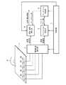
図1は、この発明の実施の形態1に係る近接検知装置の構成を示すブロック図である。近接検知装置は、検知電極2a〜2eの静電容量を出力するタッチパネル1と、検知電極2a〜2eと検知対象物の間の静電容量値を検出する静電容量検出部3と、ベースライン値を用いて検知対象物の近接及び接触を検出する近接・接触検出部4と、近接・接触検出部4で用いるベースライン値を更新する、即ち感度キャリブレーションを行うベースライン更新部5と、更新したベースライン値を格納し、近接・接触検出部4へ出力するベースライン格納部6と、これら各部の動作を制御する制御部7とを備える。
1 is a block diagram showing a configuration of a proximity detection apparatus according to
タッチパネル1には検知電極2a〜2eが配置されており、これらの検知電極2a〜2eは検知対象物であるユーザの指8(又は誘電体)の接近、近接、接触によって静電容量が変化する。なお、図1では指8がタッチパネル1に近接している状態を示す。また、指8とタッチパネル1との距離が近い順に、接触、近接、接近と称し、それぞれの状態を接触状態、近接状態(図1に示す)、接近状態と称す。
静電容量検出部3は、制御部7から検出指示信号を受けると、検知電極2a〜2eの各静電容量を順次検出し、検出した静電容量値を近接・接触検出部4とベースライン更新部5に出力する。 Upon receiving the detection instruction signal from the
一般的に、指(バーチャルグランド電極)と検知電極の間に生じる静電容量値は、(真空の誘電率)×(指と検知電極間の物質の誘電率)×(検知電極と指の重なり面積)/(指と検知電極の間の距離)で決まる。ここで、指と検知電極間の物質の誘電率は、(真空の誘電率)×(物質の比誘電率)であり、このうち真空の誘電率は固定であるから、物質の比誘電率が大きいほど指と検知電極間に生じる静電容量値は大きくなる。ここで、図1に示すように透明タイプの静電タッチパネル又は静電センサの場合、検知電極にITO(酸化インジウムスズ)等の透明電極を用いるが、通常はこの電極上面に保護用のガラス、アクリル等を重ねて被覆し、ガラス又はアクリル面への指の接触を検知する。図2に、ガラス、アクリル等、指と検知電極間の物質の比誘電率の一覧を示す。図2に示すように、ガラス及びアクリルの比誘電率に比べて空気の比誘電率は小さいので、ガラス又はアクリル面と指の間に空気層がある状態(近接状態及び接近状態)と、ガラス又はアクリル面に指が接触した状態(接触状態)とでは接触状態の方が検出される静電容量値は大きくなる。近接検知装置はこの変化を利用して検知電極に対する指の接触検知を行う。また、前述したように、指と検知電極との距離が小さいほど静電容量値は大きくなるので、その微小な変化を高精度で検出できれば、近接状態及び接近状態における指と検知電極間の大まかな距離(近接度合い及び接近度合い)が推定できることになる。通常、静電容量値の単位にはF(ファラド)が用いられるが、指と検知電極間の静電容量値の検出方法には、充放電時間の変異を計測する方法、正弦波及び矩形波等の電圧変化を計測する方法等、様々な方法があるので、本実施の形態で説明する際の静電容量値の単位は、正規化された尺度として表す。 In general, the capacitance generated between the finger (virtual ground electrode) and the sensing electrode is (dielectric constant of vacuum) x (dielectric constant of the substance between the finger and sensing electrode) x (overlap of sensing electrode and finger) Area) / (distance between finger and detection electrode). Here, the dielectric constant of the substance between the finger and the sensing electrode is (vacuum dielectric constant) × (relative dielectric constant of the substance). Among these, the dielectric constant of the vacuum is fixed, so the dielectric constant of the substance is The larger the value, the larger the capacitance value generated between the finger and the detection electrode. Here, as shown in FIG. 1, in the case of a transparent type electrostatic touch panel or an electrostatic sensor, a transparent electrode such as ITO (indium tin oxide) is used as a detection electrode. Usually, a protective glass, Acrylic or the like is overlaid and covered to detect finger contact with the glass or acrylic surface. FIG. 2 shows a list of relative dielectric constants of substances between the finger and the detection electrode, such as glass and acrylic. As shown in FIG. 2, since the relative permittivity of air is smaller than the relative permittivity of glass and acrylic, there is an air layer between the glass or acrylic surface and the finger (close state and close state), and glass. Alternatively, the capacitance value detected in the contact state becomes larger when the finger is in contact with the acrylic surface (contact state). The proximity detection device uses this change to detect contact of the finger with the detection electrode. In addition, as described above, the capacitance value increases as the distance between the finger and the detection electrode becomes smaller. A large distance (proximity and proximity) can be estimated. Usually, F (Farad) is used as the unit of the capacitance value, but as a method for detecting the capacitance value between the finger and the detection electrode, a method of measuring a variation in charge / discharge time, a sine wave and a rectangular wave Since there are various methods such as a method of measuring a voltage change such as, the unit of the capacitance value in the description in this embodiment is expressed as a normalized scale.
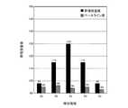
図3は、図1に示す近接状態において、静電容量検出部3が検出した検知電極2a〜2eの静電容量値(黒棒)、及びベースライン格納部6に格納されているベースライン値(斜線棒)を示すグラフである。指8が検知電極2cに近接した状態のため、静電容量値は、検知電極2cをピークとして、指8と検知電極2a〜2e間の距離に応じた静電容量分布となっている。 3 shows the capacitance values (black bars) of the
近接・接触検出部4は、制御部7から検出指示信号を受けると、静電容量検出部3から出力された静電容量値とベースライン格納部6から出力されたベースライン値とを基に、検知電極2a〜2eへの指8の近接状態及び接触状態を検出して、近接情報及び接触情報を出力する。
図4は、近接・接触検出部4による近接及び接触状態の検出処理を説明するグラフであり、図3に示す静電容量値とベースライン値との差分値を示す。近接・接触検出部4には、近接状態を判断するための近接基準容量値20と、接触状態を判断するための接触基準容量値21とが予め設定されている。図1に示すように検知電極2cに指8が近接した状態であるため、検知電極2cの静電容量値とベースライン値との差分値のみが近接基準容量値20を超えている。この場合、近接・接触検出部4は、指8が検知電極2cに近接状態であることを示す近接情報を出力する。When the proximity /
FIG. 4 is a graph for explaining the proximity and contact state detection processing by the proximity /
ベースライン更新部5は、制御部7から指示信号を受けると、静電容量検出部3から入力された静電容量値を用いて検知電極2a〜2eそれぞれのベースライン値を求め、ベースライン格納部6に出力する。ベースライン格納部6は、制御部7から格納指示信号を受けるとベースライン更新部5から出力されたベースライン値を格納し、制御部7から出力指示信号を受けると近接・接触検出部4又はベースライン更新部5に格納しているベースライン値を出力する。 When receiving the instruction signal from the
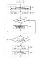
次に、近接検知装置の動作を説明する。図5は、実施の形態1に係る近接検知装置の動作を示すフローチャートである。
先ず、図1に示す近接状態における近接検知装置の動作を説明する。ステップST1において、制御部7が静電容量検出部3に指示し、静電容量検出部3が検知電極2a〜2eの静電容量値を順次検出する。静電容量検出部3は、検出した静電容量値を近接・接触検出部4及びベースライン更新部5に出力する。ここで、静電容量検出部3によって検出された静電容量値が、図3に示す黒棒である。指8が検知電極2cに近接しているので、検知電極2cの静電容量値が大きい値となっている。Next, the operation of the proximity detector will be described. FIG. 5 is a flowchart showing the operation of the proximity detection apparatus according to the first embodiment.
First, the operation of the proximity detector in the proximity state shown in FIG. 1 will be described. In step ST1, the
続くステップST2において、制御部7が近接・接触検出部4に指示し、近接・接触検出部4が静電容量値を基に、近接状態及び接触状態を検出する。具体的には、近接・接触検出部4が、各検知電極2a〜2eが出力した静電容量値からベースライン格納部6に格納されている検知電極2a〜2e毎のベースライン値を減じた差分値を求め、その差分値と近接基準容量値を比較することにより近接状態を検出すると共に、その差分値と接触基準容量値を比較することにより接触状態を検出する。
図1の例では、ベースライン格納部6が図3に斜線棒で示すベースライン値を格納しており、静電容量検出部3が同じく図3に黒棒で示す静電容量値を検出している。このため、近接・接触検出部4が求める差分値は図4に示す黒棒となり、近接基準容量値20を超えた検知電極2cについて近接状態と判断される。In subsequent step ST2, the
In the example of FIG. 1, the
続くステップST3において、制御部7は、近接・接触検出部4の判断結果に基づいて指8が近接している状態か否かを判別し、近接状態であれば処理をステップST4へ進め、そうでなければステップST7へ進める。ここでは、検知電極2cが近接状態であることを示す判断結果に基づいて、処理がステップST4へ進む。 In subsequent step ST3, the
続くステップST4において、制御部7は、近接・接触検出部4の判断結果に基づいて指8が接触している状態か否かを判別し、接触状態であれば処理をステップST5へ進め、そうでなければステップST6へ進める。ここでは、いずれの検知電極2a〜2eも接触状態ではないことを示す判断結果に基づいて、処理がステップST6へ進む。 In subsequent step ST4, the
続くステップST6において、制御部7が近接・接触検出部4に指示し、近接・接触検出部4から近接情報を出力する。近接情報は、指8が近接状態になっている検知電極の識別番号、及びその近接度合いを表す尺度を含む。この近接度合いの尺度とは、例えば図4に示す検知電極2cの差分値と近接基準容量値20との差である。 In subsequent step ST6, the
制御部7は処理を再びステップST1に戻し、次のタイミングにおける検知電極2a〜2eの静電容量値の検出を開始する。 The
次に、図6に示す、いずれの検知電極2a〜2eにも指8が近づいていない状態における近接検知装置の動作を説明する。図6は、実施の形態1に係る近接検知装置の構成を示すブロック図であり、指8(不図示)がタッチパネル1に接近していない状態を示す。
ステップST1において、制御部7が静電容量検出部3に指示し、静電容量検出部3が検知電極2a〜2eの静電容量値を順次検出する。図7は、図6に示す指8が接近していない状態において、静電容量検出部3が検出した検知電極2a〜2eの静電容量値、及びベースライン格納部6に格納されているベースライン値を示すグラフである。いずれの検知電極2a〜2eにも指8が接近、近接、接触していないので、静電容量値は小さい値となっている。静電容量検出部3は、検出した静電容量値を近接・接触検出部4及びベースライン更新部5に出力する。Next, the operation of the proximity detection device in a state where the
In step ST1, the
続くステップST2において、制御部7が近接・接触検出部4に指示し、近接・接触検出部4が静電容量値を基に、近接状態又は接触状態を検出する。図8は、図6に示す指8が接近していない状態において、近接・接触検出部4による近接及び接触状態の検出処理を説明するグラフであり、図7に示すベースライン値と静電容量値との差分値を示す。いずれの検知電極2a〜2eの差分値も近接基準容量値20及び接触基準容量値21より小さい値となっており、近接及び接触のない状態と判断される。 In subsequent step ST2, the
続くステップST3において、制御部7は、近接・接触検出部4の判断結果に基づいて指8が近接していない状態と判断して処理をステップST7へ進める。 In subsequent step ST3, the
続くステップST7において、制御部7がベースライン更新部5に指示し、ベースライン更新部5がキャリブレーションを行うか否かを判断する。指8が検知電極2a〜2eに接近していない状態では、差分値分布(静電容量値分布の情報)はランダムな分布になるが、近接状態とまではならないが接近はしている接近状態では、その影響が指8と検知電極2a〜2eの距離に応じた分布に表れる。ベースライン更新部5は、このような差分値分布の特徴を利用して指8が接近状態かどうかを判定し、接近状態になければキャリブレーションを行い(ステップST7“Yes”)、接近状態であればキャリブレーションを行わない(ステップST7“No”)。ここでは、差分値分布を判別する尺度の一例として下記式(1)に示す尖度(Kurtosis)Xkを用いることとし、ベースライン更新部5はこの尖度Xkが一定以内の場合に接近状態と判定する。なお、差分値分布は、ユーザの指8の大きさ、検知電極2a〜2eの大きさ、検知電極2a〜2e間のピッチ、レイアウト方式等によって異なる可能性があるので、このような条件に応じて尖度Xkを設定する。この例では、指8が接近した場合の尖度Xkの範囲を、−1.0<Xk<3とする。下記式(1)によれば図8の差分値分布における尖度Xkは−3.33となり、上記範囲内にないため、ベースライン更新部5は指8が接近していないと判定して、キャリブレーションを行う(ステップST7“Yes”)。
続くステップST8において、制御部7がベースライン更新部5に指示し、ベースライン更新部5が新たなベースライン値を求める。ここでは単純に、静電容量検出部3から出力された最新の、接近状態にないと判定した静電容量値を新たなベースライン値とする。その他、新たなベースライン値の求め方として、過去の一定数のサンプルまで遡った平均値を算出する方法等を用いてもよい。 In subsequent step ST8, the
続くステップST9において、制御部7がベースライン格納部6に指示し、ベースライン格納部6が、ステップST8においてベースライン更新部5で更新された新たなベースライン値を格納する。図9は、ベースライン格納部6が格納する新たなベースライン値を示す図である。 In subsequent step ST9, the
なお、ステップST7にてベースライン更新部5が接近状態と判定した場合(ステップST7“No”)には、制御部7が処理をステップST1に戻し、次のタイミングにおける検知電極2a〜2eの静電容量値の検出を開始する。 When the
次に、図10に示す接近状態における近接検知装置の動作を説明する。図10は、実施の形態1に係る近接検知装置の構成を示すブロック図であり、指8がタッチパネル1に接近している状態を示す。
ステップST1において、制御部7が静電容量検出部3に指示し、静電容量検出部3が検知電極2a〜2eの静電容量値を順次検出する。図11は、図10に示す接近状態において、静電容量検出部3が検出した検知電極2a〜2eの静電容量値、及びベースライン格納部6に格納されているベースライン値を示すグラフである。指8が検知電極2cに接近しているので、検知電極2cの静電容量値が大きい値となっている。静電容量検出部3は、検出した静電容量値を近接・接触検出部4及びベースライン更新部5に出力する。Next, the operation of the proximity detector in the approaching state shown in FIG. 10 will be described. FIG. 10 is a block diagram illustrating a configuration of the proximity detection device according to the first embodiment, and illustrates a state in which the
In step ST1, the
続くステップST2において、制御部7が近接・接触検出部4に指示し、近接・接触検出部4が静電容量値を基に、近接状態又は接触状態を検出する。図12は、図10に示す接近状態において、近接・接触検出部4による近接及び接触状態の検出処理を説明するグラフであり、図11に示すベースライン値と静電容量値との差分値を示す。いずれの検知電極2a〜2eにも指8が近接及び接触していないので、差分値は近接基準容量値20及び接触基準容量値21よりも小さい値となっており近接及び接触のない状態と判断される。ただし、指8が接近しているため、一定の値の差分値が得られている。 In subsequent step ST2, the
続くステップST3において、制御部7は、近接・接触検出部4の判断結果に基づいて指8が近接していない状態と判断して処理をステップST7へ進める。 In subsequent step ST3, the
続くステップST7において、制御部7がベースライン更新部5に指示し、ベースライン更新部5がキャリブレーションを行うか否かを判断する。図12の差分値分布における尖度Xkは−0.36となり、指8が接近した場合の尖度範囲内であるため、ベースライン更新部5は指8が接近していると判定して、キャリブレーションを行わない(ステップST7“No”)。そのため、制御部7は、ベースライン格納部6が格納しているベースライン値(図11に示す斜線棒)を、図11に示すように指8の接近の影響を受けている静電容量値に更新することなしに、処理をステップST1に戻す。 In subsequent step ST7, the
以上のように、実施の形態1によれば、指8との距離に応じて静電容量が変化する複数の検知電極2a〜2eと、検知電極2a〜2eと指8の間の静電容量値を検出する静電容量検出部3と、静電容量検出部3が検出した静電容量値とベースライン値とを用いて、指8の検知電極2a〜2eへの近接又は接触状態を判別する近接・接触検出部4と、近接・接触検出部4が用いるベースライン値を格納しておくベースライン格納部6と、静電容量検出部3が検出した静電容量値に基づいて、ベースライン格納部6に格納されているベースライン値を更新するベースライン更新部5とを備え、ベースライン更新部5が、近接・接触検出部4で指8が近接又は接触状態にないと判別された場合にベースライン値の更新可否を判定するように構成した。このため、近接・接触検出部4によって指8が近接又は接触状態にあると判別された場合にはベースライン更新部5が感度キャリブレーションを行わず、指8の近接時の誤ったキャリブレーションによるベースライン値の更新がなされないので、指8の接触状態の高精度な検出が可能になる。 As described above, according to the first embodiment, the plurality of
また、ベースライン更新部5を、近接・接触検出部4によって指8が近接又は接触状態にないと判別された場合に、更に、差分値分布に基づいて指8の接近の有無を判別してベースライン値更新可否を判定するように構成した。そのため、指8の接近時の誤ったキャリブレーションによるベースライン値の更新がされないので、指8の近接状態の高精度な検出が可能になる。 Further, when the proximity /
なお、上記実施の形態1では、近接・接触検出部4が、近接情報又は接触情報として、近接基準容量値20又は接触基準容量値21を超えた検知電極の情報を出力する構成としたが、この他にも例えば、最大出力の検知電極の情報又は各検知電極間に生じる静電容量を補間処理によって求めた座標情報(即ち仮想的なピーク情報)を出力する構成にしてもよい。 In the first embodiment, the proximity /
また、ベースライン更新部5で指の接近有無を判定する際に尖度Xkを用いる構成としたが、これに限定されるものではなく、指の接近を判定できる情報であれば、別の尺度を用いてもよい。また、上記実施の形態1では、指の接近有無を判定するための尖度範囲を予め規定していたが、ベースライン更新部5にユーザの指の情報を登録しておき、ユーザの指の大きさに応じた尖度範囲に変更して接近有無を判定するようにしてもよい。また、この判定の際にベースライン更新部5は全ての検知電極の差分値を使用したが、指の接近判定に必要な数の検知電極に絞って使用してもよい。また、この判定の際にベースライン更新部5は1つの時点のサンプル(即ち、近接及び接触がない状態における検知電極2a〜2eの1時点の差分値分布の情報)を使用したが、時間方向の複数のサンプル(即ち、近接及び接触がない状態における検知電極2a〜2eの複数時点の差分値分布の時間推移情報)を使用してもよい。 Also, the kurtosis Xk is used when the
また、上記実施の形態1では、1次元に配置された検知電極2a〜2eの静電容量値を用いる構成を例に近接検知装置を説明したが、2次元に配置された検知電極の静電容量値を用いる構成であってもよい。図13は、実施の形態1に係る近接検知装置の他の構成例を示すブロック図である。この構成の場合には、ベースライン更新部5で指の接近有無を判定する際に、2次元的な差分値分布等を利用することができる。 In the first embodiment, the proximity detection device has been described by taking the configuration using the capacitance values of the
また、上記実施の形態1では、近接検知装置が接触状態だけでなく近接状態も検出する構成としたが、接触状態のみを検出して接触情報のみを出力する構成にしてもよい。図14は、実施の形態1に係る近接検知装置の他の動作例を示すフローチャートである。近接検知装置が接触状態のみを検出する構成の場合には、図14のステップST2において近接・接触検出部4が指の接触状態のみ検出することとし、続くステップST4において制御部7で指が接触していない状態(近接状態)と判断した場合(ステップST4“No”)に、ステップST7においてベースライン更新部5が指の接近有無を判定するように構成すればよい。 In the first embodiment, the proximity detection device detects not only the contact state but also the proximity state. However, only the contact state may be detected and only the contact information may be output. FIG. 14 is a flowchart illustrating another operation example of the proximity detection apparatus according to the first embodiment. In the case where the proximity detection device is configured to detect only the contact state, the proximity /
1 タッチパネル、2a〜2e 検知電極、3 静電容量検出部、4 近接・接触検出部、5 ベースライン更新部、6 ベースライン格納部、7 制御部、8 指、20 近接基準容量値、21 接触基準容量値。 DESCRIPTION OF
Claims (3)
Translated fromJapanese前記検知電極と検知対象物間の静電容量値を検出する静電容量検出部と、
前記静電容量検出部が検出した静電容量値とベースライン値とを用いて、検知対象物の前記検知電極への近接又は接触状態を判別する近接・接触検出部と、
前記近接・接触検出部が用いるベースライン値を格納しておくベースライン格納部と、
前記静電容量検出部が検出した静電容量値に基づいて、前記ベースライン格納部に格納されているベースライン値を更新するベースライン更新部とを備え、
前記ベースライン更新部は、前記近接・接触検出部で検知対象物が近接又は接触状態にないと判別された場合にベースライン値の更新可否を判定し、更新可のときに前記ベースライン格納部のベースライン値を更新することを特徴とする近接検知装置。A plurality of detection electrodes whose capacitance changes according to the distance to the detection object;
A capacitance detector for detecting a capacitance value between the detection electrode and the detection object;
A proximity / contact detection unit that determines the proximity or contact state of the detection object to the detection electrode using the capacitance value and the baseline value detected by the capacitance detection unit;
A baseline storage unit for storing a baseline value used by the proximity / contact detection unit;
A baseline update unit that updates a baseline value stored in the baseline storage unit based on the capacitance value detected by the capacitance detection unit;
The baseline update unit determines whether or not the baseline value can be updated when the proximity / contact detection unit determines that the detection target is not in proximity or in a contact state, and when the update is possible, the baseline storage unit A proximity detection device that updates the baseline value of the.
Priority Applications (1)
| Application Number | Priority Date | Filing Date | Title |
|---|---|---|---|
| JP2009103981AJP2010257046A (en) | 2009-04-22 | 2009-04-22 | Proximity detector |
Applications Claiming Priority (1)
| Application Number | Priority Date | Filing Date | Title |
|---|---|---|---|
| JP2009103981AJP2010257046A (en) | 2009-04-22 | 2009-04-22 | Proximity detector |
Publications (1)
| Publication Number | Publication Date |
|---|---|
| JP2010257046Atrue JP2010257046A (en) | 2010-11-11 |
Family
ID=43317916
Family Applications (1)
| Application Number | Title | Priority Date | Filing Date |
|---|---|---|---|
| JP2009103981APendingJP2010257046A (en) | 2009-04-22 | 2009-04-22 | Proximity detector |
Country Status (1)
| Country | Link |
|---|---|
| JP (1) | JP2010257046A (en) |
Cited By (46)
| Publication number | Priority date | Publication date | Assignee | Title |
|---|---|---|---|---|
| JP2012150747A (en)* | 2011-01-21 | 2012-08-09 | Mitsubishi Electric Corp | Touch panel device |
| WO2012157291A1 (en)* | 2011-05-13 | 2012-11-22 | シャープ株式会社 | Touch panel device, display device, touch panel device calibration method, program, and recording medium |
| JP2012234473A (en)* | 2011-05-09 | 2012-11-29 | Renesas Sp Drivers Inc | Touch detection device and semiconductor device |
| JP2013097510A (en)* | 2011-10-31 | 2013-05-20 | Minebea Co Ltd | Input device and input control method of electronic apparatus |
| JP2013114472A (en)* | 2011-11-29 | 2013-06-10 | Minebea Co Ltd | Input device of electronic apparatus and input control method |
| JP2013130939A (en)* | 2011-12-20 | 2013-07-04 | Minebea Co Ltd | Input device |
| JP2013130912A (en)* | 2011-12-20 | 2013-07-04 | Konica Minolta Business Technologies Inc | Information processing apparatus, calibration method, and computer program |
| JP2013190850A (en)* | 2012-03-12 | 2013-09-26 | Denso Corp | Display device |
| JP2013257658A (en)* | 2012-06-11 | 2013-12-26 | Fujitsu Ltd | Information terminal equipment and depression determination method |
| JP2014049137A (en)* | 2012-08-30 | 2014-03-17 | Huwei Device Co Ltd | Method for calibration of capacitive touch screen and capacitive touch apparatus |
| JP2014106829A (en)* | 2012-11-29 | 2014-06-09 | Mitsubishi Electric Corp | Touch panel apparatus |
| CN104063100A (en)* | 2013-03-18 | 2014-09-24 | 阿尔卑斯电气株式会社 | Static capacitance type touchpad |
| JP2014527325A (en)* | 2011-06-29 | 2014-10-09 | マイクロチップ テクノロジー ジャーマニー ツー ゲーエムベーハー ウント コンパニー カーゲー | Capacitive sensor device and method for calibrating a capacitive sensor device |
| JP2014217019A (en)* | 2013-04-30 | 2014-11-17 | 株式会社ユーシン | Touch switch and operation panel |
| JP2014229284A (en)* | 2013-05-27 | 2014-12-08 | 株式会社ジャパンディスプレイ | Touch detecting apparatus, display apparatus with touch detecting function, and electronic equipment |
| WO2015050108A1 (en)* | 2013-10-01 | 2015-04-09 | シャープ株式会社 | Portable terminal and control method |
| WO2015050130A1 (en)* | 2013-10-01 | 2015-04-09 | シャープ株式会社 | Portable terminal and control method |
| WO2015087621A1 (en)* | 2013-12-11 | 2015-06-18 | シャープ株式会社 | Touch sensor control device |
| JP2015118655A (en)* | 2013-12-20 | 2015-06-25 | エルジー ディスプレイ カンパニー リミテッド | Touch detection device and touch detection method |
| US9104282B2 (en) | 2012-10-04 | 2015-08-11 | Canon Kabushiki Kaisha | Electronic device, control method of electronic device, program, and storage medium |
| JP2016021266A (en)* | 2015-10-30 | 2016-02-04 | ミネベア株式会社 | Input device |
| EP3101514A1 (en) | 2015-05-14 | 2016-12-07 | Alps Electric Co., Ltd. | Input device and method of operating input device |
| JP2017111507A (en)* | 2015-12-14 | 2017-06-22 | 株式会社東海理化電機製作所 | Touch input device |
| EP3220243A1 (en) | 2016-03-15 | 2017-09-20 | Alps Electric Co., Ltd. | Input device, control method of input device, and program |
| EP3123290A4 (en)* | 2014-03-26 | 2017-10-11 | Intel Corporation | Capacitive sensor action in response to proximity sensor data |
| US9823327B2 (en) | 2012-10-01 | 2017-11-21 | Denso Corporation | Touch detection device and vehicular navigation apparatus |
| EP3220247A3 (en)* | 2016-02-29 | 2017-12-13 | Alps Electric Co., Ltd. | Determination device and determination method |
| FR3062933A1 (en)* | 2017-02-16 | 2018-08-17 | Dav | CONTROL MODULE FOR A VEHICLE |
| US10073574B2 (en) | 2015-10-26 | 2018-09-11 | Semiconductor Components Industries, Llc | Methods and apparatus for a capacitive sensor |
| US10073564B2 (en) | 2016-03-15 | 2018-09-11 | Alps Electric Co., Ltd. | Input device, control method of input device, and program |
| WO2018193711A1 (en)* | 2017-04-20 | 2018-10-25 | アルプス電気株式会社 | Touch sensor-type electronic device and sensor control method |
| CN108924319A (en)* | 2018-08-30 | 2018-11-30 | 维沃移动通信有限公司 | A kind of proximity test method and mobile terminal |
| JP2019145484A (en)* | 2018-02-23 | 2019-08-29 | パナソニックIpマネジメント株式会社 | Electrostatic sensor device |
| WO2019176429A1 (en)* | 2018-03-12 | 2019-09-19 | アルプスアルパイン株式会社 | Input device, input device control method, and program |
| EP3654155A1 (en) | 2018-11-14 | 2020-05-20 | Alpine Electronics, Inc. | Electronic device equipped with touch panel and update method of base line value |
| US10719182B2 (en) | 2018-02-27 | 2020-07-21 | Kabushiki Kaisha Tokai Rika Denki Seisakusho | Touch sensor device and capacitance calibration method |
| US10739902B2 (en) | 2017-09-27 | 2020-08-11 | Hyundai Motor Company | Input apparatus and control method of the same |
| US10754472B2 (en) | 2018-02-27 | 2020-08-25 | Kabushiki Kaisha Tokai Rika Denki Seisakusho | Touch sensor device and capacitance calibration method |
| JP2020194256A (en)* | 2019-05-27 | 2020-12-03 | 京セラドキュメントソリューションズ株式会社 | Display input device and image forming device |
| US11010045B2 (en) | 2018-05-31 | 2021-05-18 | Canon Kabushiki Kaisha | Control apparatus, control method, and non-transitory computer readable medium |
| JPWO2021100348A1 (en)* | 2019-11-19 | 2021-05-27 | ||
| CN113497615A (en)* | 2020-04-05 | 2021-10-12 | 昇佳电子股份有限公司 | Proximity detection method and circuit thereof |
| WO2022014160A1 (en)* | 2020-07-16 | 2022-01-20 | アルプスアルパイン株式会社 | Gesture identifying device |
| JP7426455B1 (en) | 2022-09-30 | 2024-02-01 | 住友理工株式会社 | Contact detection device |
| WO2025046851A1 (en)* | 2023-08-31 | 2025-03-06 | 三菱電機ビルソリューションズ株式会社 | Input device |
| US12445129B2 (en) | 2021-04-05 | 2025-10-14 | Sensortek Technology Corp. | Proximity detection method and circuit thereof |
Citations (3)
| Publication number | Priority date | Publication date | Assignee | Title |
|---|---|---|---|---|
| JP2005267478A (en)* | 2004-03-22 | 2005-09-29 | Hitachi Ltd | Proximity position input device |
| JP2007076491A (en)* | 2005-09-14 | 2007-03-29 | Hitachi Ltd | In-vehicle equipment operation device |
| JP2007286814A (en)* | 2006-04-14 | 2007-11-01 | Alps Electric Co Ltd | Input device |
- 2009
- 2009-04-22JPJP2009103981Apatent/JP2010257046A/enactivePending
Patent Citations (3)
| Publication number | Priority date | Publication date | Assignee | Title |
|---|---|---|---|---|
| JP2005267478A (en)* | 2004-03-22 | 2005-09-29 | Hitachi Ltd | Proximity position input device |
| JP2007076491A (en)* | 2005-09-14 | 2007-03-29 | Hitachi Ltd | In-vehicle equipment operation device |
| JP2007286814A (en)* | 2006-04-14 | 2007-11-01 | Alps Electric Co Ltd | Input device |
Cited By (72)
| Publication number | Priority date | Publication date | Assignee | Title |
|---|---|---|---|---|
| JP2012150747A (en)* | 2011-01-21 | 2012-08-09 | Mitsubishi Electric Corp | Touch panel device |
| JP2012234473A (en)* | 2011-05-09 | 2012-11-29 | Renesas Sp Drivers Inc | Touch detection device and semiconductor device |
| WO2012157291A1 (en)* | 2011-05-13 | 2012-11-22 | シャープ株式会社 | Touch panel device, display device, touch panel device calibration method, program, and recording medium |
| JP2012242860A (en)* | 2011-05-13 | 2012-12-10 | Sharp Corp | Touch panel device, display device, touch panel device calibration method, program, and recording medium |
| JP2014527325A (en)* | 2011-06-29 | 2014-10-09 | マイクロチップ テクノロジー ジャーマニー ツー ゲーエムベーハー ウント コンパニー カーゲー | Capacitive sensor device and method for calibrating a capacitive sensor device |
| JP2013097510A (en)* | 2011-10-31 | 2013-05-20 | Minebea Co Ltd | Input device and input control method of electronic apparatus |
| JP2013114472A (en)* | 2011-11-29 | 2013-06-10 | Minebea Co Ltd | Input device of electronic apparatus and input control method |
| JP2013130939A (en)* | 2011-12-20 | 2013-07-04 | Minebea Co Ltd | Input device |
| JP2013130912A (en)* | 2011-12-20 | 2013-07-04 | Konica Minolta Business Technologies Inc | Information processing apparatus, calibration method, and computer program |
| JP2013190850A (en)* | 2012-03-12 | 2013-09-26 | Denso Corp | Display device |
| JP2013257658A (en)* | 2012-06-11 | 2013-12-26 | Fujitsu Ltd | Information terminal equipment and depression determination method |
| JP2014049137A (en)* | 2012-08-30 | 2014-03-17 | Huwei Device Co Ltd | Method for calibration of capacitive touch screen and capacitive touch apparatus |
| US9529475B2 (en) | 2012-08-30 | 2016-12-27 | Huawei Device Co., Ltd. | Method for calibration of capacitive touch screen and capacitive touch apparatus |
| US9823327B2 (en) | 2012-10-01 | 2017-11-21 | Denso Corporation | Touch detection device and vehicular navigation apparatus |
| US9104282B2 (en) | 2012-10-04 | 2015-08-11 | Canon Kabushiki Kaisha | Electronic device, control method of electronic device, program, and storage medium |
| JP2014106829A (en)* | 2012-11-29 | 2014-06-09 | Mitsubishi Electric Corp | Touch panel apparatus |
| CN104063100A (en)* | 2013-03-18 | 2014-09-24 | 阿尔卑斯电气株式会社 | Static capacitance type touchpad |
| JP2014182471A (en)* | 2013-03-18 | 2014-09-29 | Alps Electric Co Ltd | Capacitance type touchpad |
| CN104063100B (en)* | 2013-03-18 | 2017-09-01 | 阿尔卑斯电气株式会社 | Electrostatic capacitive touch panel |
| JP2014217019A (en)* | 2013-04-30 | 2014-11-17 | 株式会社ユーシン | Touch switch and operation panel |
| JP2014229284A (en)* | 2013-05-27 | 2014-12-08 | 株式会社ジャパンディスプレイ | Touch detecting apparatus, display apparatus with touch detecting function, and electronic equipment |
| JP2015073161A (en)* | 2013-10-01 | 2015-04-16 | シャープ株式会社 | Portable terminal and control method |
| WO2015050108A1 (en)* | 2013-10-01 | 2015-04-09 | シャープ株式会社 | Portable terminal and control method |
| JP2015073160A (en)* | 2013-10-01 | 2015-04-16 | シャープ株式会社 | Mobile terminal and control method |
| WO2015050130A1 (en)* | 2013-10-01 | 2015-04-09 | シャープ株式会社 | Portable terminal and control method |
| WO2015087621A1 (en)* | 2013-12-11 | 2015-06-18 | シャープ株式会社 | Touch sensor control device |
| US9710108B2 (en) | 2013-12-11 | 2017-07-18 | Sharp Kabushiki Kaisha | Touch sensor control device having a calibration unit for calibrating detection sensitivity of a touch except for a mask region |
| JP2015118655A (en)* | 2013-12-20 | 2015-06-25 | エルジー ディスプレイ カンパニー リミテッド | Touch detection device and touch detection method |
| EP3123290A4 (en)* | 2014-03-26 | 2017-10-11 | Intel Corporation | Capacitive sensor action in response to proximity sensor data |
| EP3101514A1 (en) | 2015-05-14 | 2016-12-07 | Alps Electric Co., Ltd. | Input device and method of operating input device |
| US9851846B2 (en) | 2015-05-14 | 2017-12-26 | Alps Electric Co., Ltd. | Input device and method of operating input device |
| US10114515B2 (en) | 2015-10-26 | 2018-10-30 | Semiconductor Components Industries, Llc | Methods and apparatus for a capacitive sensor |
| US10430008B2 (en) | 2015-10-26 | 2019-10-01 | Semiconductor Components Industries, Llc | Methods and apparatus for a 3-dimensional capacitive sensor having multi-operation electrodes |
| US10073574B2 (en) | 2015-10-26 | 2018-09-11 | Semiconductor Components Industries, Llc | Methods and apparatus for a capacitive sensor |
| US10088963B2 (en) | 2015-10-26 | 2018-10-02 | Semiconductor Components Industries, Llc | Methods and apparatus for a capacitive sensor |
| US10310694B2 (en) | 2015-10-26 | 2019-06-04 | Semiconductor Components Industries, Llc | Methods and apparatus for a capacitive sensor |
| JP2016021266A (en)* | 2015-10-30 | 2016-02-04 | ミネベア株式会社 | Input device |
| JP2017111507A (en)* | 2015-12-14 | 2017-06-22 | 株式会社東海理化電機製作所 | Touch input device |
| EP3220247A3 (en)* | 2016-02-29 | 2017-12-13 | Alps Electric Co., Ltd. | Determination device and determination method |
| EP3220243A1 (en) | 2016-03-15 | 2017-09-20 | Alps Electric Co., Ltd. | Input device, control method of input device, and program |
| US10073564B2 (en) | 2016-03-15 | 2018-09-11 | Alps Electric Co., Ltd. | Input device, control method of input device, and program |
| FR3062933A1 (en)* | 2017-02-16 | 2018-08-17 | Dav | CONTROL MODULE FOR A VEHICLE |
| WO2018149897A1 (en)* | 2017-02-16 | 2018-08-23 | Dav | Command module for vehicle cabin |
| WO2018193711A1 (en)* | 2017-04-20 | 2018-10-25 | アルプス電気株式会社 | Touch sensor-type electronic device and sensor control method |
| CN110520831A (en)* | 2017-04-20 | 2019-11-29 | 阿尔卑斯阿尔派株式会社 | Touch sensor formula electronic device and sensor control method |
| JPWO2018193711A1 (en)* | 2017-04-20 | 2020-05-14 | アルプスアルパイン株式会社 | Touch sensor type electronic device and sensor control method |
| CN110520831B (en)* | 2017-04-20 | 2023-06-20 | 阿尔卑斯阿尔派株式会社 | Touch sensor electronic device and sensor control method |
| US11216135B2 (en) | 2017-04-20 | 2022-01-04 | Alps Alpine Co., Ltd. | Touch-sensitive electronic device and sensor control method |
| US10739902B2 (en) | 2017-09-27 | 2020-08-11 | Hyundai Motor Company | Input apparatus and control method of the same |
| JP2019145484A (en)* | 2018-02-23 | 2019-08-29 | パナソニックIpマネジメント株式会社 | Electrostatic sensor device |
| JP7038326B2 (en) | 2018-02-23 | 2022-03-18 | パナソニックIpマネジメント株式会社 | Electrostatic sensor device |
| US10754472B2 (en) | 2018-02-27 | 2020-08-25 | Kabushiki Kaisha Tokai Rika Denki Seisakusho | Touch sensor device and capacitance calibration method |
| US10719182B2 (en) | 2018-02-27 | 2020-07-21 | Kabushiki Kaisha Tokai Rika Denki Seisakusho | Touch sensor device and capacitance calibration method |
| EP3767442B1 (en)* | 2018-03-12 | 2025-04-02 | Alps Alpine Co., Ltd. | Input device, input device control method, and program |
| JPWO2019176429A1 (en)* | 2018-03-12 | 2020-10-22 | アルプスアルパイン株式会社 | Input devices, input device control methods, and programs |
| CN111819527A (en)* | 2018-03-12 | 2020-10-23 | 阿尔卑斯阿尔派株式会社 | Input device, control method of input device, and program |
| WO2019176429A1 (en)* | 2018-03-12 | 2019-09-19 | アルプスアルパイン株式会社 | Input device, input device control method, and program |
| US11010045B2 (en) | 2018-05-31 | 2021-05-18 | Canon Kabushiki Kaisha | Control apparatus, control method, and non-transitory computer readable medium |
| CN108924319A (en)* | 2018-08-30 | 2018-11-30 | 维沃移动通信有限公司 | A kind of proximity test method and mobile terminal |
| EP3654155A1 (en) | 2018-11-14 | 2020-05-20 | Alpine Electronics, Inc. | Electronic device equipped with touch panel and update method of base line value |
| US10866677B2 (en) | 2018-11-14 | 2020-12-15 | Alpine Electronics, Inc. | Electronic device equipped with touch panel and update method of base line value |
| CN111190507B (en)* | 2018-11-14 | 2024-05-10 | 阿尔派株式会社 | Electronic device with touch panel and method for updating baseline value |
| CN111190507A (en)* | 2018-11-14 | 2020-05-22 | 阿尔派株式会社 | Electronic device with touch panel and baseline value updating method |
| JP2020194256A (en)* | 2019-05-27 | 2020-12-03 | 京セラドキュメントソリューションズ株式会社 | Display input device and image forming device |
| JP7298299B2 (en) | 2019-05-27 | 2023-06-27 | 京セラドキュメントソリューションズ株式会社 | Display input device and image forming device |
| JPWO2021100348A1 (en)* | 2019-11-19 | 2021-05-27 | ||
| CN113497615A (en)* | 2020-04-05 | 2021-10-12 | 昇佳电子股份有限公司 | Proximity detection method and circuit thereof |
| WO2022014160A1 (en)* | 2020-07-16 | 2022-01-20 | アルプスアルパイン株式会社 | Gesture identifying device |
| US12445129B2 (en) | 2021-04-05 | 2025-10-14 | Sensortek Technology Corp. | Proximity detection method and circuit thereof |
| JP7426455B1 (en) | 2022-09-30 | 2024-02-01 | 住友理工株式会社 | Contact detection device |
| JP2024052065A (en)* | 2022-09-30 | 2024-04-11 | 住友理工株式会社 | Contact Detection Device |
| WO2025046851A1 (en)* | 2023-08-31 | 2025-03-06 | 三菱電機ビルソリューションズ株式会社 | Input device |
Similar Documents
| Publication | Publication Date | Title |
|---|---|---|
| JP2010257046A (en) | Proximity detector | |
| US8976153B2 (en) | Touch panel device detecting water | |
| US9069399B2 (en) | Gain correction for fast panel scanning | |
| TWI433004B (en) | Method for determining touch points on touch panel and system thereof | |
| JP5656666B2 (en) | Touch panel device | |
| US8686964B2 (en) | User specific recognition of intended user interaction with a digitizer | |
| US11556190B2 (en) | Capacitive touch panel for sensing mechanical inputs to a device | |
| CN106462288B (en) | touch input device | |
| JP6369805B2 (en) | Touch sensor device, electronic device, and touch gesture detection program | |
| KR102061863B1 (en) | Touch sensing device and driving method thereof | |
| US8188970B2 (en) | System and method for automatic re-calulation and monitoring of thresholds in a puck-based pointing device | |
| WO2008087638A1 (en) | System and method for calibration of a capacitive touch digitizer system | |
| TW201602869A (en) | Projected capacitive touch with force detection | |
| EP2107445A1 (en) | Optical pointing device and method of detecting click event in optical pointing device | |
| EP3132330B1 (en) | Determining touch locations and forces thereto on a touch and force sensing surface | |
| CN103270478B (en) | The intelligent sketching equipment of the method for detected target object and implementation methods described in interference environment | |
| CN107735754A (en) | Operation detection device | |
| TW201423512A (en) | Touch panel system, and electronic information device | |
| KR101143276B1 (en) | Adaptive type noise removing method for improving the accuracy of the position measurement of touch input | |
| JP6104370B2 (en) | Touch sensor screen with capacitive sensor array and capacitive sensor array | |
| JP6739193B2 (en) | Touch panel | |
| TWI502416B (en) | Sensing apparatus for touch panel and sensing method thereof | |
| KR101619081B1 (en) | A calibration method for increasing the touch of a capacitive touch sensor sensitivity of the mutual capacitance | |
| KR101620830B1 (en) | A calibration method for increasing the touch of a capacitive touch sensor sensitivity of the self capacitance | |
| KR101204352B1 (en) | Device and method for touch detection in a capacitive touch panel using constant current source |
Legal Events
| Date | Code | Title | Description |
|---|---|---|---|
| A621 | Written request for application examination | Free format text:JAPANESE INTERMEDIATE CODE: A621 Effective date:20120119 | |
| A977 | Report on retrieval | Free format text:JAPANESE INTERMEDIATE CODE: A971007 Effective date:20121031 | |
| A131 | Notification of reasons for refusal | Free format text:JAPANESE INTERMEDIATE CODE: A131 Effective date:20121106 | |
| A02 | Decision of refusal | Free format text:JAPANESE INTERMEDIATE CODE: A02 Effective date:20130305 |