JP2010253156A - Endoscope system, endoscope, and endoscope driving method - Google Patents
Endoscope system, endoscope, and endoscope driving methodDownload PDFInfo
- Publication number
- JP2010253156A JP2010253156AJP2009108983AJP2009108983AJP2010253156AJP 2010253156 AJP2010253156 AJP 2010253156AJP 2009108983 AJP2009108983 AJP 2009108983AJP 2009108983 AJP2009108983 AJP 2009108983AJP 2010253156 AJP2010253156 AJP 2010253156A
- Authority
- JP
- Japan
- Prior art keywords
- image
- shift
- guide
- image guide
- shift mechanism
- Prior art date
- Legal status (The legal status is an assumption and is not a legal conclusion. Google has not performed a legal analysis and makes no representation as to the accuracy of the status listed.)
- Abandoned
Links
Images


Classifications
- A—HUMAN NECESSITIES
- A61—MEDICAL OR VETERINARY SCIENCE; HYGIENE
- A61B—DIAGNOSIS; SURGERY; IDENTIFICATION
- A61B1/00—Instruments for performing medical examinations of the interior of cavities or tubes of the body by visual or photographical inspection, e.g. endoscopes; Illuminating arrangements therefor
- A61B1/00163—Optical arrangements
- A61B1/00188—Optical arrangements with focusing or zooming features
- A—HUMAN NECESSITIES
- A61—MEDICAL OR VETERINARY SCIENCE; HYGIENE
- A61B—DIAGNOSIS; SURGERY; IDENTIFICATION
- A61B1/00—Instruments for performing medical examinations of the interior of cavities or tubes of the body by visual or photographical inspection, e.g. endoscopes; Illuminating arrangements therefor
- A61B1/00002—Operational features of endoscopes
- A61B1/00004—Operational features of endoscopes characterised by electronic signal processing
- A61B1/00006—Operational features of endoscopes characterised by electronic signal processing of control signals
- A—HUMAN NECESSITIES
- A61—MEDICAL OR VETERINARY SCIENCE; HYGIENE
- A61B—DIAGNOSIS; SURGERY; IDENTIFICATION
- A61B1/00—Instruments for performing medical examinations of the interior of cavities or tubes of the body by visual or photographical inspection, e.g. endoscopes; Illuminating arrangements therefor
- A61B1/00002—Operational features of endoscopes
- A61B1/00043—Operational features of endoscopes provided with output arrangements
- A61B1/00045—Display arrangement
- A61B1/0005—Display arrangement combining images e.g. side-by-side, superimposed or tiled
- A—HUMAN NECESSITIES
- A61—MEDICAL OR VETERINARY SCIENCE; HYGIENE
- A61B—DIAGNOSIS; SURGERY; IDENTIFICATION
- A61B1/00—Instruments for performing medical examinations of the interior of cavities or tubes of the body by visual or photographical inspection, e.g. endoscopes; Illuminating arrangements therefor
- A61B1/00163—Optical arrangements
- A61B1/00165—Optical arrangements with light-conductive means, e.g. fibre optics
- A61B1/00167—Details of optical fibre bundles, e.g. shape or fibre distribution
- A—HUMAN NECESSITIES
- A61—MEDICAL OR VETERINARY SCIENCE; HYGIENE
- A61B—DIAGNOSIS; SURGERY; IDENTIFICATION
- A61B1/00—Instruments for performing medical examinations of the interior of cavities or tubes of the body by visual or photographical inspection, e.g. endoscopes; Illuminating arrangements therefor
- A61B1/012—Instruments for performing medical examinations of the interior of cavities or tubes of the body by visual or photographical inspection, e.g. endoscopes; Illuminating arrangements therefor characterised by internal passages or accessories therefor
- A61B1/018—Instruments for performing medical examinations of the interior of cavities or tubes of the body by visual or photographical inspection, e.g. endoscopes; Illuminating arrangements therefor characterised by internal passages or accessories therefor for receiving instruments
- G—PHYSICS
- G02—OPTICS
- G02B—OPTICAL ELEMENTS, SYSTEMS OR APPARATUS
- G02B23/00—Telescopes, e.g. binoculars; Periscopes; Instruments for viewing the inside of hollow bodies; Viewfinders; Optical aiming or sighting devices
- G02B23/24—Instruments or systems for viewing the inside of hollow bodies, e.g. fibrescopes
- G02B23/26—Instruments or systems for viewing the inside of hollow bodies, e.g. fibrescopes using light guides
- H—ELECTRICITY
- H04—ELECTRIC COMMUNICATION TECHNIQUE
- H04N—PICTORIAL COMMUNICATION, e.g. TELEVISION
- H04N23/00—Cameras or camera modules comprising electronic image sensors; Control thereof
- H04N23/10—Cameras or camera modules comprising electronic image sensors; Control thereof for generating image signals from different wavelengths
- H04N23/13—Cameras or camera modules comprising electronic image sensors; Control thereof for generating image signals from different wavelengths with multiple sensors
- H—ELECTRICITY
- H04—ELECTRIC COMMUNICATION TECHNIQUE
- H04N—PICTORIAL COMMUNICATION, e.g. TELEVISION
- H04N25/00—Circuitry of solid-state image sensors [SSIS]; Control thereof
- H04N25/48—Increasing resolution by shifting the sensor relative to the scene
- A—HUMAN NECESSITIES
- A61—MEDICAL OR VETERINARY SCIENCE; HYGIENE
- A61B—DIAGNOSIS; SURGERY; IDENTIFICATION
- A61B1/00—Instruments for performing medical examinations of the interior of cavities or tubes of the body by visual or photographical inspection, e.g. endoscopes; Illuminating arrangements therefor
- A61B1/06—Instruments for performing medical examinations of the interior of cavities or tubes of the body by visual or photographical inspection, e.g. endoscopes; Illuminating arrangements therefor with illuminating arrangements
- A61B1/0653—Instruments for performing medical examinations of the interior of cavities or tubes of the body by visual or photographical inspection, e.g. endoscopes; Illuminating arrangements therefor with illuminating arrangements with wavelength conversion
- A—HUMAN NECESSITIES
- A61—MEDICAL OR VETERINARY SCIENCE; HYGIENE
- A61B—DIAGNOSIS; SURGERY; IDENTIFICATION
- A61B1/00—Instruments for performing medical examinations of the interior of cavities or tubes of the body by visual or photographical inspection, e.g. endoscopes; Illuminating arrangements therefor
- A61B1/06—Instruments for performing medical examinations of the interior of cavities or tubes of the body by visual or photographical inspection, e.g. endoscopes; Illuminating arrangements therefor with illuminating arrangements
- A61B1/07—Instruments for performing medical examinations of the interior of cavities or tubes of the body by visual or photographical inspection, e.g. endoscopes; Illuminating arrangements therefor with illuminating arrangements using light-conductive means, e.g. optical fibres
- G—PHYSICS
- G02—OPTICS
- G02B—OPTICAL ELEMENTS, SYSTEMS OR APPARATUS
- G02B6/00—Light guides; Structural details of arrangements comprising light guides and other optical elements, e.g. couplings
- G02B6/04—Light guides; Structural details of arrangements comprising light guides and other optical elements, e.g. couplings formed by bundles of fibres
- G02B6/06—Light guides; Structural details of arrangements comprising light guides and other optical elements, e.g. couplings formed by bundles of fibres the relative position of the fibres being the same at both ends, e.g. for transporting images
- G02B6/065—Light guides; Structural details of arrangements comprising light guides and other optical elements, e.g. couplings formed by bundles of fibres the relative position of the fibres being the same at both ends, e.g. for transporting images with dynamic image improvement
- G—PHYSICS
- G02—OPTICS
- G02B—OPTICAL ELEMENTS, SYSTEMS OR APPARATUS
- G02B6/00—Light guides; Structural details of arrangements comprising light guides and other optical elements, e.g. couplings
- G02B6/24—Coupling light guides
- G02B6/42—Coupling light guides with opto-electronic elements
- G02B6/4298—Coupling light guides with opto-electronic elements coupling with non-coherent light sources and/or radiation detectors, e.g. lamps, incandescent bulbs, scintillation chambers
- H—ELECTRICITY
- H04—ELECTRIC COMMUNICATION TECHNIQUE
- H04N—PICTORIAL COMMUNICATION, e.g. TELEVISION
- H04N23/00—Cameras or camera modules comprising electronic image sensors; Control thereof
- H04N23/50—Constructional details
- H04N23/555—Constructional details for picking-up images in sites, inaccessible due to their dimensions or hazardous conditions, e.g. endoscopes or borescopes
Landscapes
- Health & Medical Sciences (AREA)
- Life Sciences & Earth Sciences (AREA)
- Surgery (AREA)
- Physics & Mathematics (AREA)
- Engineering & Computer Science (AREA)
- Optics & Photonics (AREA)
- Biomedical Technology (AREA)
- Veterinary Medicine (AREA)
- Biophysics (AREA)
- Pathology (AREA)
- Radiology & Medical Imaging (AREA)
- Nuclear Medicine, Radiotherapy & Molecular Imaging (AREA)
- Public Health (AREA)
- Heart & Thoracic Surgery (AREA)
- Medical Informatics (AREA)
- Molecular Biology (AREA)
- Animal Behavior & Ethology (AREA)
- General Health & Medical Sciences (AREA)
- Signal Processing (AREA)
- Multimedia (AREA)
- Astronomy & Astrophysics (AREA)
- General Physics & Mathematics (AREA)
- Endoscopes (AREA)
- Closed-Circuit Television Systems (AREA)
- Instruments For Viewing The Inside Of Hollow Bodies (AREA)
Abstract
Translated fromJapaneseDescription
Translated fromJapanese本発明は、内視鏡システム、内視鏡、並びに内視鏡駆動方法に関する。 The present invention relates to an endoscope system, an endoscope, and an endoscope driving method.
医療分野において、内視鏡は今や欠くことのできない医療器具の一つである。内視鏡は、いわゆる胃カメラやファイバスコープを使用していた黎明期から、現在はCCD等のイメージセンサを用いた電子内視鏡、あるいは患者に飲み込ませて体内画像を取得するカプセル型内視鏡が開発されるに到り、着実に技術的進歩を遂げている。 In the medical field, an endoscope is now an indispensable medical instrument. Endoscopes have been used since the early days when so-called gastric cameras and fiberscopes were used, and are now electronic endoscopes using image sensors such as CCDs, or capsule endoscopes that can be swallowed by a patient to obtain in-vivo images. As mirrors are developed, they are making steady technological progress.
内視鏡検査の分野では、患者の体内に挿入する挿入部の極細径化が希求されている。実際、現在に到るまで様々な細径化の試みがなされており、例えば膵管、胆管、乳管、気管支末端といった細管部の観察が可能な内視鏡も検討されている。 In the field of endoscopy, there is a demand for ultra-thin diameter insertion portions that are inserted into a patient's body. In fact, various attempts have been made to reduce the diameter until now, and endoscopes capable of observing narrow tubes such as pancreatic ducts, bile ducts, breast ducts, and bronchial ends have been studied.
ファイバスコープは、極言すれば、体内の被観察部位の像を伝達するイメージガイドと被観察部位に照明光を照射するライトガイドさえあれば体内画像を取得することが可能であるため、構造上極細径化に向いている。しかしながら、イメージガイドを構成する光ファイバ束のクラッドが像の伝達に寄与しないので、クラッドを投影した網目模様が体内画像に映り込み、体内画像の画質が悪くなるという問題があった。 In other words, the fiberscope can acquire in-vivo images as long as there is an image guide that transmits the image of the site to be observed in the body and a light guide that irradiates illumination light to the site to be observed. Suitable for diameter. However, since the clad of the optical fiber bundle constituting the image guide does not contribute to image transmission, there is a problem in that the mesh pattern projected on the clad is reflected in the in-vivo image and the image quality of the in-vivo image is deteriorated.
上記問題を踏まえて、特許文献1の第一実施形態のファイバスコープは、イメージガイドの入射端に配置された、イメージガイドの入射端に結像させるレンズ等の結像系光学部材を圧電素子で振動させることで、体内画像に網目模様が映り込むことを防止している。圧電素子は、イメージガイドの光ファイバまたはCCDの画素の配列ピッチに応じて、結像系光学部材を上下左右方向に所定量振動させている。 In view of the above problem, the fiberscope of the first embodiment of
また、特許文献1の第二実施形態では、イメージガイドを用いずに、挿入部の先端にCCDを配置した例が開示されている。第二実施形態では、CCDの前方に配置された結像系光学部材を第一実施形態と同じく振動させている。そして、この振動の間に、時分割的にCCDの画素で像を受光し、得られたデータをフレームメモリに順次記憶して一フレーム分の画像を得ることで、高解像度化を実現している。 In the second embodiment of
特許文献2には、ホワイトボードを撮像して得た参照画像の網目部分に該当する撮影画像の部分を、白色に置換、隣接する画素で置換、周囲の画素で置換、あるいは補間値を演算して置換することで、撮影画像の網目模様を除去する技術が記載されている。 In
特許文献3では、白色被写体を撮影して得られた白画像から、イメージガイドを構成する光ファイバのコアの、画像(固体撮像素子の撮像面)上の中心座標を抽出している。そして、白画像の各画素の明度を均すように補正し、中心座標に対応する画素以外の画素を、二次元的な補間埋め込み処理で補間している。 In
結像系光学部材は、画像の明るさを確保するために、イメージガイドよりも径が大きいが、特許文献1では、結像系光学部材を圧電素子で振動させている。このため、ただでさえイメージガイドよりも径が大きい結像系光学部材を揺動可能に保持するための枠体や保持機構を取り付けるスペースがさらに必要になり、その分挿入部の径方向寸法が大きくなる。つまり、結像系光学部材を圧電素子で振動させることは、極細径化の妨げとなる。数十μm〜数mmオーダーの極細径化を目指すためには、枠体や保持機構の取り付けスペースですら憂慮すべき問題となる。 The imaging system optical member has a diameter larger than that of the image guide in order to ensure the brightness of the image. However, in
特許文献1の第二実施形態は、高解像度化は実現可能となるものの、結像系光学部材に加えてCCDを挿入部先端に配置する構成であるため、極細径化には程遠い。 In the second embodiment of
特許文献2、3に記載の方法は、網目模様の除去はできるが、画像化に寄与する画素の数は増えないため、たとえ画素補間を施したとしても高解像度化には限界がある。 Although the methods described in
本発明は、上記背景を鑑みてなされたものであり、その目的は、極細径化の達成と質の高い体内画像の取得という要請を両方満たすことにある。 The present invention has been made in view of the above-described background, and an object thereof is to satisfy both the requirements of achieving ultra-thin diameter and obtaining a high-quality in-vivo image.
上記目的を達成するために、本発明の内視鏡システムは、複数本の光ファイバをバンドル化してなるイメージガイド、イメージセンサ、シフト機構、同期制御手段、および画像合成手段を備えることを特徴とする。 In order to achieve the above object, an endoscope system according to the present invention includes an image guide formed by bundling a plurality of optical fibers, an image sensor, a shift mechanism, a synchronization control unit, and an image synthesis unit. To do.
前記イメージガイドは、内視鏡の挿入部に挿通され、対物光学系で入射端に結像された被観察部位の像を出射端に伝達する。前記イメージセンサは、前記イメージガイドで伝達された像を撮像する。 The image guide is inserted into the insertion portion of the endoscope, and transmits an image of the observation site imaged at the entrance end by the objective optical system to the exit end. The image sensor captures an image transmitted by the image guide.
前記シフト機構は、前記イメージガイドの入射端の外周に形成された圧電素子で前記イメージガイドの入射端を揺動させ、対物光学系で結像された像に対して前記イメージガイドの入射端を周期的にシフト動作させる。 The shift mechanism swings the incident end of the image guide with a piezoelectric element formed on the outer periphery of the incident end of the image guide, and moves the incident end of the image guide with respect to the image formed by the objective optical system. Shift operation is performed periodically.
前記同期制御手段は、前記シフト機構によるシフト動作に同期して前記イメージセンサに複数回撮像させ、対物光学系で結像された像に対する前記イメージガイドの入射端の位置が異なる状態で撮像された複数の画像が得られるよう、前記イメージセンサと前記シフト機構の動作を制御する。 The synchronization control means causes the image sensor to capture images a plurality of times in synchronization with the shift operation by the shift mechanism, and images are captured in a state where the position of the incident end of the image guide with respect to the image formed by the objective optical system is different. The operations of the image sensor and the shift mechanism are controlled so that a plurality of images can be obtained.
前記画像合成手段は、前記イメージガイドの各光ファイバで伝達された像と前記イメージセンサの画素の撮像面上の位置関係、および前記シフト機構でシフトされる前記イメージガイドのシフト量の情報に基づき、得られた複数の画像を合成して、一つの合成画像を生成する。 The image synthesizing means is based on the positional relationship between the image transmitted by each optical fiber of the image guide and the pixel of the image sensor on the imaging surface, and information on the shift amount of the image guide shifted by the shift mechanism. Then, a plurality of obtained images are synthesized to generate one synthesized image.
無地の単色被写体を撮像して得た参照画像を元に、位置関係の情報を取得する情報取得手段を備えることが好ましい。前記情報取得手段は、所定期間毎に得られる参照画像から、その都度位置関係の情報を取得する。前記情報取得手段は、参照画像に対して二値化処理を施してマスク画像を生成する二値化処理手段と、生成されたマスク画像に基づいて、前記イメージセンサの撮像面上における、各光ファイバで伝達された像の中心位置を検出する位置検出手段とからなる。 It is preferable to include information acquisition means for acquiring positional relationship information based on a reference image obtained by imaging a solid monochrome subject. The information acquisition unit acquires positional information from a reference image obtained every predetermined period. The information acquisition means includes: binarization processing means for performing a binarization process on a reference image to generate a mask image; and each light on the imaging surface of the image sensor based on the generated mask image. And position detecting means for detecting the center position of the image transmitted by the fiber.
前記画像合成手段は、前記位置検出手段で検出された中心位置を中心とし、光ファイバのコア径を直径とする結像領域を光ファイバ毎に設定する。そして、各結像領域内における前記イメージセンサの画素の画素値に基づいて、各結像領域の画素値の代表値を算出する。 The image synthesizing unit sets, for each optical fiber, an imaging region centered on the center position detected by the position detecting unit and having a core diameter of the optical fiber as a diameter. Then, based on the pixel value of the pixel of the image sensor in each imaging region, a representative value of the pixel value of each imaging region is calculated.
前記画像合成手段は、各結像領域内における前記イメージセンサの画素の画素値の平均値、または最大値を代表値として算出する。また、前記画像合成手段は、前記シフト機構によるシフト動作に同期して前記イメージセンサに複数回撮像させて得られた複数の画像単位で代表値を算出する。 The image synthesizing unit calculates an average value or a maximum value of pixel values of the pixels of the image sensor in each imaging region as a representative value. The image synthesizing unit calculates a representative value in units of a plurality of images obtained by causing the image sensor to capture images a plurality of times in synchronization with a shift operation by the shift mechanism.
前記画像合成手段は、シフト量の情報に応じて、前記イメージセンサの該当する画素の画素値に代表値をマッピングする。前記画像合成手段は、前記位置検出手段で検出された中心位置にシフト量を加算し、代表値をマッピングする前記イメージセンサの該当する画素を特定する。 The image synthesizing unit maps the representative value to the pixel value of the corresponding pixel of the image sensor according to the shift amount information. The image synthesizing unit adds a shift amount to the center position detected by the position detecting unit, and specifies a corresponding pixel of the image sensor to which a representative value is mapped.
前記画像合成手段は、結像領域内の画素のうち、代表値がマッピングされた画素の画素値から、マッピングされていない画素の画素値を生成する。 The image synthesizing unit generates a pixel value of an unmapped pixel from a pixel value of a pixel to which a representative value is mapped among the pixels in the imaging region.
前記シフト機構は、前記イメージガイドの入射端を第一の位置から第二の位置、第二の位置から第三の位置と順に移動させ、最後は第一の位置に戻すことで一回の周期的なシフト動作をさせる。前記イメージセンサは、各位置でその都度撮像する。 The shift mechanism moves the incident end of the image guide from the first position to the second position, from the second position to the third position in order, and finally returns to the first position for one cycle. Shift operation. The image sensor captures an image at each position.
あるいは、前記シフト機構は、前記イメージガイドの入射端を第一の位置から第二の位置に移動させたら止め、さらに第二の位置から第三の位置に移動させたら止めるという間欠シフト動作を繰り返す。 Alternatively, the shift mechanism repeats an intermittent shift operation that stops when the incident end of the image guide is moved from the first position to the second position, and stops when it is further moved from the second position to the third position. .
前記シフト機構で前記イメージガイドの入射端が移動させられる各位置の距離は、前記イメージガイドを構成する光ファイバの配列ピッチの1/nに相当する。各位置の数は四個、または九個であり、辺のなす角が60°および120°で一辺が二個、または三個の位置を結ぶ線からなる菱形をなす。 The distance of each position at which the incident end of the image guide is moved by the shift mechanism corresponds to 1 / n of the arrangement pitch of the optical fibers constituting the image guide. The number of each position is four or nine, and it forms a rhombus composed of a line connecting two or three positions where the angle between the sides is 60 ° and 120 ° and one side is two or three.
前記シフト機構は、前記イメージガイドの入射端を、各位置を巡る最短の移動経路で移動させることが好ましい。 It is preferable that the shift mechanism moves the incident end of the image guide along the shortest movement path around each position.
前記シフト機構は、前記イメージガイドの入射端が内挿固定され、前記イメージガイドの入射端をシフト動作可能な状態で保持する保持筒を有する。前記保持筒の外周面には前記圧電素子が形成され、前記圧電素子の駆動力が前記保持筒を介して前記イメージガイドに伝えられる。 The shift mechanism includes a holding cylinder in which an incident end of the image guide is inserted and fixed and holds the incident end of the image guide in a state in which a shift operation is possible. The piezoelectric element is formed on the outer peripheral surface of the holding cylinder, and the driving force of the piezoelectric element is transmitted to the image guide via the holding cylinder.
本発明の内視鏡は、複数本の光ファイバをバンドル化してなるイメージガイドと、シフト機構を備えることを特徴とする。 The endoscope of the present invention includes an image guide formed by bundling a plurality of optical fibers, and a shift mechanism.
前記イメージガイドは、挿入部に挿通され、対物光学系で入射端に結像された被観察部位の像を出射端に伝達する。 The image guide is inserted into the insertion portion, and transmits an image of the site to be observed formed at the entrance end by the objective optical system to the exit end.
前記シフト機構は、前記イメージガイドの入射端の外周に形成された圧電素子で前記イメージガイドの入射端を揺動させ、対物光学系で結像された像に対して前記イメージガイドの入射端を周期的にシフト動作させる。 The shift mechanism swings the incident end of the image guide with a piezoelectric element formed on the outer periphery of the incident end of the image guide, and moves the incident end of the image guide with respect to the image formed by the objective optical system. Shift operation is performed periodically.
前記シフト機構によるシフト動作に同期してイメージセンサに複数回撮像させ、対物光学系で結像された像に対する前記イメージガイドの入射端の位置が異なる状態で撮像された複数の画像が得られるよう、前記イメージセンサと前記シフト機構の動作が制御される。そして、前記イメージガイドの各光ファイバで伝達された像と前記イメージセンサの画素の撮像面上の位置関係、および前記シフト機構でシフトされる前記イメージガイドのシフト量の情報に基づき、得られた複数の画像を合成して、一つの合成画像が生成される。 Synchronizing with the shift operation by the shift mechanism, the image sensor can capture images a plurality of times so that a plurality of images captured with different positions of the incident end of the image guide with respect to the image formed by the objective optical system can be obtained. The operations of the image sensor and the shift mechanism are controlled. And obtained based on the positional relationship of the image transmitted through each optical fiber of the image guide and the image sensor pixel on the imaging surface and the shift amount of the image guide shifted by the shift mechanism. A plurality of images are combined to generate a single combined image.
本発明の内視鏡駆動方法は、複数本の光ファイバをバンドル化してなるイメージガイドであり、内視鏡の挿入部に挿通され、対物光学系で入射端に結像された被観察部位の像を出射端に伝達するイメージガイドの入射端を、その外周に形成された圧電素子で揺動させ、対物光学系で結像された像に対してイメージガイドの入射端を周期的にシフト動作させるステップと、シフト動作に同期してイメージセンサに複数回撮像させるステップと、イメージガイドの各光ファイバで伝達された像とイメージセンサの画素の撮像面上の位置関係、およびシフト機構でシフトされるイメージガイドのシフト量の情報に基づき、複数回の撮像により得られた、対物光学系で結像された像に対するイメージガイドの入射端の位置が異なる状態で撮像された複数の画像を合成して、画像合成手段で一つの合成画像を生成するステップとを備えることを特徴とする。 The endoscope driving method of the present invention is an image guide formed by bundling a plurality of optical fibers, inserted through the insertion portion of the endoscope, and imaged at the incident end by the objective optical system. The incident end of the image guide that transmits the image to the exit end is swung by a piezoelectric element formed on the outer periphery thereof, and the incident end of the image guide is periodically shifted with respect to the image formed by the objective optical system. A step of causing the image sensor to image a plurality of times in synchronization with the shift operation, a positional relationship between the image transmitted by each optical fiber of the image guide and the pixel of the image sensor, and a shift mechanism. Based on information on the shift amount of the image guide, a plurality of images taken with different positions of the incident end of the image guide with respect to the image formed by the objective optical system obtained by multiple times of imaging. Image by synthesizing the, characterized in that it comprises the steps of generating a single combined image in the image synthesizing means.
本発明によれば、イメージガイドの入射端をシフト機構で周期的にシフト動作させ、このシフト動作に同期してイメージセンサで複数回の撮像を行い、イメージガイドの各光ファイバで伝達された像とイメージセンサの画素の撮像面上の位置関係、およびシフト機構でシフトされるイメージガイドのシフト量の情報に基づき、複数回の撮像で得られた複数の画像から一つの合成画像を生成するので、極細径化の達成と質の高い体内画像の取得という要請を両方満たすことができる。 According to the present invention, the incident end of the image guide is periodically shifted by the shift mechanism, the image sensor performs imaging a plurality of times in synchronization with the shift operation, and the image transmitted through each optical fiber of the image guide. And a single composite image from multiple images obtained by multiple imaging based on the positional relationship between the image sensor pixels on the imaging surface and information on the shift amount of the image guide shifted by the shift mechanism Therefore, it is possible to satisfy both the requirements for achieving ultra-thin diameter and obtaining high-quality in-vivo images.
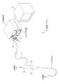
図1において、内視鏡システム2は、内視鏡10、プロセッサ装置11、および光源装置12からなる。内視鏡10は、例えば膵管、胆管、乳管、気管支末端といった細管部を観察する際に用いられる。内視鏡10は、患者の体内に挿入される可撓性の挿入部13と、挿入部13の基端部分に連設された操作部14と、プロセッサ装置11および光源装置12にそれぞれ接続されるプロセッサ用コネクタ15および光源用コネクタ16と、操作部14、各コネクタ15、16間を繋ぐユニバーサルコード17とを有する。 In FIG. 1, the
挿入部13は、例えば厚み50μm、外径0.9mmのテフロン(登録商標)等の可撓性材料からなる。操作部14には、体内画像を静止画記録するためのレリーズボタン18といった操作部材が設けられている。また、操作部14の先端側には、電気メス等の処置具が挿通される鉗子口19が設けられている。鉗子口19は、挿入部13内の鉗子チャンネル46(図3参照)を通して、挿入部13の先端部20に設けられた鉗子出口26(図2参照)に連通している。 The insertion portion 13 is made of a flexible material such as Teflon (registered trademark) having a thickness of 50 μm and an outer diameter of 0.9 mm, for example. The
プロセッサ装置11は、光源装置12と電気的に接続され、内視鏡システム2の動作を統括的に制御する。プロセッサ装置11は、ユニバーサルコード17や挿入部13内に挿通された配線ケーブル45(図3参照)を介して内視鏡10に給電を行い、シフト機構32(図3参照)の駆動を制御する。また、プロセッサ装置11は、イメージガイド31(図3参照)で伝達された被観察部位の像を、内蔵のCCD58R、58G、58B(図6参照、以下、まとめてCCD58という)で受像し、これにより得られた撮像信号に各種処理を施して画像を生成する。プロセッサ装置11で生成された画像は、プロセッサ装置11にケーブル接続されたモニタ21に体内画像として表示される。 The
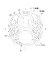
先端部20は、例えば厚み25μm、外径0.8mmのステンレス製パイプを基体とする。図2において、先端部20の先端面20aには、上方中央に観察窓25が、その直下に鉗子出口26が設けられている。また、観察窓25、鉗子出口26以外の隙間を埋めるように、複数のライトガイド27の先端がランダムに配置されている。 The
鉗子出口26は、例えば外径0.34mm、内径0.3mmであり、ポリイミド等からなる鉗子チャンネル46(図3参照)に連通している。ライトガイド27は、例えば外径50μmの光ファイバからなる。ライトガイド27は、挿入部13、ユニバーサルコード17に亘って挿通され、その入射端が光源用コネクタ16内に位置している。ライトガイド27は、入射端に入射した光源装置12からの照明光を導光して、先端面20aから露呈した先端(出射端)から照明光を被観察部位に照射する。 The
ライトガイド27は、複数本の光ファイバをバラで挿入部13内に挿通させ、その後先端部20に接着剤を流し込むことで先端部20に固着される。必要に応じて、固着後にライトガイド27の出射端を表面研磨したり、各ライトガイド27の出射端前方に、ライトガイド27の出射端が配された部分を覆う照明窓を設けてもよい。さらには、照明窓に蛍光物質を塗り込む等して照明光を拡散させてもよい。 The
図3に示すように、観察窓25の奥には、対物光学系30、イメージガイド31、およびイメージガイド31をシフトさせるシフト機構32が配されている。対物光学系30は、鏡筒33に保持され、被観察部位の像をイメージガイド31の入射端に結像させる。対物光学系30、鏡筒33の外径はそれぞれ、例えば0.35mm、0.4mmである。また、鏡筒33の軸方向長さは、例えば3.2mmである。 As shown in FIG. 3, behind the
イメージガイド31は、例えば外径0.2mmの光ファイバ束からなる(図5参照)。イメージガイド31は、挿入部13、ユニバーサルコード17内を挿通され、その出射端がプロセッサ用コネクタ15内に位置している。イメージガイド31は、対物光学系30に面した入射端から取り込んだ被観察部位の像を出射端に伝達する。 The
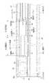
図4にも示すように、シフト機構32は、保持筒34、圧電素子35、および電極36で構成される。保持筒34は、例えば外径0.26mm、内径0.2mmのステンレス製パイプからなり、イメージガイド31が内挿固定される。圧電素子35は、例えば厚み15μmであり、保持筒34の外周面を覆う円筒状に成膜されている。電極36は、例えば厚み5μmであり、圧電素子35の外周面に成膜されている。 As shown in FIG. 4, the
シフト機構32は、先端部20の基体内に収容されている。シフト機構32の外周面と先端部20の基体の内周面との間には、例えば0.1mm程度の空洞37が形成されている。 The
シフト機構32は、イメージガイド31の入射端とともに揺動する、先端面20a側の揺動部38と、イメージガイド31とともに固定される、挿入部13側の固定部39とに分れる。揺動部38では、シフト機構32は先端部20の基体に固着されておらず、イメージガイド31は、固定部39を支点として空洞37内を揺動可能である。固定部39では、シフト機構32は接着剤40で先端部20の基体の内周面に固着されている。接着剤40は、イメージガイド31が剥き出しになるシフト機構32の終端手前から、挿入部13の先端途中に掛けて充填されている。揺動部38、固定部39の軸方向長さはそれぞれ、例えば4mm、1.9mmであり、固定部39と挿入部13の先端途中を含む接着剤40の充填範囲の軸方向長さは、例えば3.2mmである。 The
電極36は、周方向に90°間隔(図2の上下左右方向に対して45°傾いた位置)に設けられ、軸方向に平行に形成された四本の溝41によって、上下、左右の二対、計四個に分割されている。揺動部38では、各電極36の間隔が溝41の幅分しか空いておらず、各電極36が幅広となっている。対して、固定部39では溝41が周方向に対称に拡がった形の切欠き42が形成されて、幅狭部43となっている。幅狭部43は、圧電素子35の後端付近まで延在している。溝41および切欠き42は、圧電素子35の外周面全体に電極材料を成膜した後、エッチングによって形成される。 The
幅狭部43の終端にはパッド44が形成され、パッド44には配線ケーブル45が接続されている。パッド44は、保持筒34の終端にも形成されており、これにも配線ケーブル45が接続されている。すなわち、保持筒34は、圧電素子35の共通電極としても機能する。 A
配線ケーブル45は、例えば導線径15μm、被覆外径20μmである。配線ケーブル45は、イメージガイド31の周囲を這うように挿入部13、ユニバーサルコード17内を挿通され、プロセッサ用コネクタ15を介してプロセッサ装置11に接続される。 The
上下、左右で対になった電極36には、共通電極である保持筒34に掛かる電圧を基準として、逆の極性の電圧が供給される。例えば保持筒34の電位が0Vであった場合、上側の電極36には+5V、下側には−5Vといった具合である。こうすることで電極36下の圧電素子35が軸方向に伸縮し、この圧電素子35の伸縮に連れて、固定部39から先の揺動部38が、イメージガイド31の入射端とともに空洞37内を揺動する。電圧を供給する電極36の組み合わせや印加電圧の値を種々変更することで、揺動部38を所定角度で所定量移動させることができる。 The
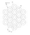
図5において、イメージガイド31は、周知の如く、コア50とクラッド51からなる複数本(例えば6000本)の光ファイバ52を、六角最密状に束ねてバンドル化した構成である。本例では、コア50、クラッド51の径はそれぞれ、3μm、6μmであり、光ファイバ52の配列ピッチPは6μmである。 In FIG. 5, the
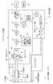
図6において、プロセッサ装置11は、拡大光学系55および三板式CCD56を有する。拡大光学系55は、プロセッサ用コネクタ15から露呈したイメージガイド31の出射端に面する箇所に配置されている。拡大光学系55は、イメージガイド31で伝達された被観察部位の像を、適当な倍率で拡大して三板式CCD56に入射させる。 In FIG. 6, the
三板式CCD56は、拡大光学系55の背後に配置されている。三板式CCD56は、周知の如く、色分解プリズム57と、三台のCCD58とから構成される。色分解プリズム57は、三個のプリズムブロックと、プリズムブロックの接合面に配された二枚のダイクロイックミラーとからなる。色分解プリズム57は、拡大光学系55からの被観察部位の像を赤、青、緑色の波長帯域を有する光に分け、それぞれの光をCCD58に向けて出射する。CCD58は、色分解プリズム57からの各色光の入射光量に応じた撮像信号を出力する。なお、CCDの代わりにCMOSイメージセンサを用いてもよい。 The three-
イメージガイド31のコア50で伝達する像80を、画素81が配列されたCCD58の撮像面に投影した図7において、像80の中心は、画素81の九個分の枡目の中心と略一致する。イメージガイド31の出射端と色分解プリズム57、CCD58は、像80と画素81が図示する位置関係となるように位置決めされている。 In FIG. 7 in which the image 80 transmitted by the
図6に戻って、CCD58からの撮像信号は、アナログフロントエンド(以下、AFEと略す)59に入力される。AFE59は、相関二重サンプリング回路(以下、CDSと略す)、自動ゲイン制御回路(以下、AGCと略す)、およびアナログ/デジタル変換器(以下、A/Dと略す)から構成されている。CDSは、CCD58から出力される撮像信号に対して相関二重サンプリング処理を施し、CCD58で生じるリセット雑音およびアンプ雑音の除去を行う。AGCは、CDSによりノイズ除去が行われた撮像信号を所定のゲイン(増幅率)で増幅する。A/Dは、AGCにより増幅された撮像信号を、所定のビット数のデジタル信号に変換する。A/Dでデジタル化された撮像信号は、デジタル信号処理回路(以下、DSPと略す)65のフレームメモリ(図示せず)に一旦格納される。 Returning to FIG. 6, the imaging signal from the CCD 58 is input to an analog front end (hereinafter abbreviated as AFE) 59. The
CCD駆動回路60は、CCD58の駆動パルス(垂直/水平走査パルス、電子シャッタパルス、読み出しパルス、リセットパルス等)とAFE59用の同期パルスとを発生する。CCD58は、CCD駆動回路60からの駆動パルスに応じて撮像動作を行い、撮像信号を出力する。AFE59の各部は、CCD駆動回路60からの同期パルスに基づいて動作する。なお、図では便宜上、CCD駆動回路60とAFE59はCCD58Gのみに繋がれているが、これらは実際にはCCD58R、58Bにも繋がれている。 The
圧電素子駆動回路61は、配線ケーブル45を介して電極36および保持筒34に繋がれている。圧電素子駆動回路61は、CPU62の制御の下、圧電素子35に電圧を供給する。 The piezoelectric
CPU62は、プロセッサ装置11全体の動作を統括的に制御する。CPU62は、図示しないデータバスやアドレスバス、制御線を介して各部と接続している。ROM63には、プロセッサ装置11の動作を制御するための各種プログラム(OS、アプリケーションプログラム等)やデータ(グラフィックデータ等)が記憶されている。CPU62は、ROM63から必要なプログラムやデータを読み出して、作業用メモリであるRAM64に展開し、読み出したプログラムを逐次処理する。また、CPU62は、検査日時、患者や術者の情報等の文字情報といった検査毎に変わる情報を、後述する操作部68やLAN(Local Area Network)等のネットワークより得て、RAM64に記憶する。 The
DSP65は、AFE59からの撮像信号をフレームメモリから読み出す。DSP65は、読み出した撮像信号に対して、色分離、色補間、ゲイン補正、ホワイトバランス調整、ガンマ補正等の各種信号処理を施し、一フレーム分の画像を生成する。またDSP65は、後述するシフト撮影モードが選択されたときに、シフトの一周期で得られた複数の画像を合成して一つの高解像度な画像(以下、合成画像という)を出力する画像合成部65a(図10参照)を有する。このためDSP65には、複数のフレームメモリが設けられている。DSP65で生成された画像(合成画像も含む)は、デジタル画像処理回路(以下、DIPと略す)66のフレームメモリ(図示せず)に入力される。 The
DIP66は、CPU62の制御に従って各種画像処理を実行する。DIP66は、DSP65で処理された画像をフレームメモリから読み出す。DIP66は、読み出した画像に対して、電子変倍、あるいは色強調、エッジ強調等の各種画像処理を施す。DIP66で各種画像処理を施された画像は、表示制御回路67に入力される。 The
表示制御回路67は、DIP66からの処理済みの画像を格納するVRAMを有する。表示制御回路67は、CPU62からROM63およびRAM64のグラフィックデータを受け取る。グラフィックデータには、体内画像の無効画素領域を隠して有効画素領域のみを表示させる表示用マスク、検査日時、あるいは患者や術者の情報等の文字情報、グラフィカルユーザインターフェース(GUI;Graphical User Interface)といったものがある。表示制御回路67は、DIP66からの画像に対して、表示用マスク、文字情報、GUIの重畳処理、モニタ21の表示画面への描画処理といった各種表示制御処理を施す。 The
表示制御回路67は、VRAMから画像を読み出し、読み出した画像をモニタ21の表示形式に応じたビデオ信号(コンポーネント信号、コンポジット信号等)に変換する。これにより、モニタ21に体内画像が表示される。 The
操作部68は、プロセッサ装置11の筐体に設けられる操作パネル、内視鏡10の操作部14にあるボタン、あるいは、マウスやキーボード等の周知の入力デバイスである。CPU62は、操作部68からの操作信号に応じて、各部を動作させる。 The
プロセッサ装置11には、上記の他にも、画像に所定の圧縮形式(例えばJPEG形式)で画像圧縮を施す圧縮処理回路や、レリーズボタン18の操作に連動して、圧縮された画像をCFカード、光磁気ディスク(MO)、CD−R等のリムーバブルメディアに記録するメディアI/F、LAN等のネットワークとの間で各種データの伝送制御を行うネットワークI/F等が設けられている。これらはデータバス等を介してCPU62と接続されている。 In addition to the above, the
光源装置12は、光源70を有する。光源70は、赤から青までのブロードな波長の光(例えば、480nm以上750nm以下の波長帯の光)を発生するキセノンランプや白色LED(発光ダイオード)等である。光源70は、光源ドライバ71によって駆動される。絞り機構72は、光源70の光射出側に配置され、集光レンズ73に入射される光量を増減させる。集光レンズ73は、絞り機構72を通過した光を集光して、ライトガイド27の入射端に導光する。CPU74は、プロセッサ装置11のCPU62と通信し、光源ドライバ71および絞り機構72の動作制御を行う。 The light source device 12 has a
内視鏡システム2には、シフト機構32を動作させないで撮影する検査準備モードおよび通常撮影モードと、シフト機構32を使用するシフト撮影モードとが用意されている。シフト撮影モードでは、シフト回数を四回、九回の二種類設定することが可能である。各モードの切り替えおよびシフト回数の設定は、操作部68を操作することにより行われる。 The
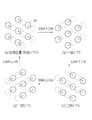
シフト撮影モードが選択されてシフト回数が四回に設定(以下、単に四回シフトという)された場合、圧電素子駆動回路61は、シフト機構32の揺動部38を駆動して、イメージガイド31の入射端を図8に示すようにシフト動作させる。まず、揺動部38は、(a)の初期位置から30°左斜め下方向に、光ファイバ52の配列ピッチPの半分、つまり1/2P分イメージガイド31の入射端を揺動させ、(b)に示す一回シフトの位置に移動させる。そして、順次右斜め下方向、右斜め上方向、左斜め上方向に、最初と同じ角度、同じ移動量でシフトさせて、(c)の二回シフト、(d)の三回シフトの位置に移動させ、再び(a)の初期位置(四回シフトの位置)に戻す。揺動部38は、圧電素子駆動回路61によって、各シフト位置でその都度止められる。なお、実線はイメージガイド31の入射端における実際のコア50の位置、破線は一つ前の位置を表す。 When the shift photographing mode is selected and the number of shifts is set to four (hereinafter, simply referred to as four shifts), the piezoelectric
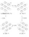
イメージガイド31の入射端におけるコア50は、(a)〜(d)、そして再び(a)に戻る一周期のシフト動作を繰り返すことで、(a)の初期位置だけでは画像化されないクラッド51の部分を埋めるような、図9(a)に示す菱形状の移動軌跡を辿る。 The core 50 at the incident end of the
因みにシフト回数が九回に設定(以下、単に九回シフトという)された場合の移動軌跡は、例えば図9(b)に示す如くである。四回シフトの場合と比べて、各方向へのシフト動作が一回多くなる。但し、七回シフトから八回シフトの位置に移るときは、六回シフトから七回シフトの位置に移ったときの左斜め上方向から、左斜め下方向に方向が変えられる。また、八回シフトから初期位置(九回シフトの位置)に移るときは、角度が90°に変えられて上方向に移動される。九回シフトの場合も四回シフトの場合と同様に、初期位置だけでは画像化されないクラッド51の部分を埋めるような移動軌跡となる。そのうえ、隣接する三つのコア50の初期位置と同じ位置(二回、四回、六回シフトの位置)に移動される。 Incidentally, the movement trajectory when the number of shifts is set to nine (hereinafter simply referred to as nine shifts) is as shown in FIG. 9B, for example. The shift operation in each direction is increased once compared to the case of four shifts. However, when shifting from the seventh shift to the eight shift position, the direction is changed from the diagonally upper left direction to the diagonally lower left direction when moving from the sixth shift to the seventh shift position. Further, when moving from the eighth shift to the initial position (position of nine shifts), the angle is changed to 90 ° and moved upward. In the case of the nine-time shift, similarly to the case of the four-time shift, the movement trajectory fills the portion of the
図10において、シフト撮影モードが選択されると、プロセッサ装置11のCPU62には、同期制御部62a、圧電素子制御部62bが構築され、また、DSP65の画像合成部65aが動作する。画像合成部65aおよび各制御部62a、62bは、シフト情報85に基づいて互いに協働しながら各種処理を行う。 In FIG. 10, when the shift photographing mode is selected, a
シフト情報85は、シフト機構32の揺動部38のシフト動作に関する情報である。シフト情報85は、シフト回数、シフト方向とそのピッチ(シフト量)、コア50の径、コア50で伝達する像80とCCD58の画素81の位置関係等を含む。シフト回数の情報は操作部68から与えられる。シフト方向、シフト量、コア50の径といった基本的な情報は例えばROM63に記憶されており、ROM63から画像合成部65aおよび各制御部62a、62bに読み出される。なお、コア50の径としては、後述する二値化画像Gwbで像80として認識可能な領域の径を用いてもよい。 The
検査準備モードは、イメージガイド31のコア50で伝達する像80とCCD58の画素81の位置関係を取得するためのモードである。検査準備モードは、内視鏡検査の前にその都度実行される。検査準備モードでは、DSP65の二値化処理部65b、および中心座標検出部65cが動作する。 The inspection preparation mode is a mode for acquiring the positional relationship between the image 80 transmitted by the
検査準備モードでは、まず、例えば白板等の無地の白色被写体を内視鏡10で撮影する。こうして得られた画像(以下、白色画像という)Gwは、図11(A)に示すように、コア50と対面する画素81得られた、複数の白丸の像80が斑点状に配列されたものとなる。斜線で示す白丸の像80以外の部分は、像80が伝達されないクラッド51に対応する部分であり、これが網目模様として映る。 In the inspection preparation mode, first, a plain white subject such as a white board is photographed by the
図11(B)に示すように、DSP65の二値化処理部65bは、白色画像Gwに対して二値化処理を施し、白黒の二値化画像(マスク画像)Gwbを生成する。二値化処理部65bは、ある閾値を基準として、各画素81で出力された撮像信号を白か黒に二分する。このため、図示するように、中心部分と比較して伝達効率が悪くなりがちな像80の辺縁部に対応する画素81が二値化処理によって黒と認識され、像80が円形でなくなる場合もある。 As shown in FIG. 11B, the binarization processing unit 65b of the
DSP65の中心座標検出部65cは、二値化処理後の各像80の中心Oを、形状認識等の周知の画像処理技術によって求め、さらに中心Oに位置する各画素81の座標(以下、中心座標という)を求める。座標は、CCD58の水平方向をX軸、垂直方向をY軸、例えば左隅を原点として、(X、Y)で表す(図14参照)。中心座標は、二値化処理の説明でも述べたように、二値化処理後に像80の形状が円形でなくなることがあるため、図7に示す像80の中心と一致しないこともある。 The center coordinate detection unit 65c of the
中心座標検出部65cは、求めた中心座標(X1、Y1)、(X2、Y2)、・・・と個々の光ファイバ52を識別するファイバNo.F1、F2、・・・とを、像80と画素81の位置関係の情報としてDSP65の内部メモリ65dに格納する(図14参照)。ファイバNo.は、座標の原点に近いほうから(左から右、上から下の)順に付される。 The center coordinate detection unit 65c is a fiber No. for identifying the individual optical fibers 52 and the obtained center coordinates (X1, Y1), (X2, Y2),. F1, F2,... Are stored in the internal memory 65d of the
同期制御部62aは、CCD駆動回路60からCCD58の駆動パルスの情報を受けて、圧電素子制御部62bに圧電素子制御信号Saを、画像合成部65aに画像合成信号Sbをそれぞれ送信する。圧電素子制御部62bは、圧電素子制御信号Saに同期してシフト動作が行われるよう、圧電素子駆動回路61の動作を制御する。同様に、画像合成部65aは、画像合成信号Sbに同期して画像合成処理を実行し、各回のシフト位置で得られた画像G0、G1、G2、G3(四回シフトの場合を例示)の画素を、各シフト位置に対応させてマッピングすることにより、一つの合成画像Gcを生成する。 The
より詳しくは、四回シフトの場合を例示した図12において、同期制御部62aは、CCD58の電荷蓄積が終了した直後、すなわちCCD58の画素81から垂直転送路に一フレーム分の信号電荷が読み出されたとき(CCD駆動回路60からCCD58に読み出しパルスが出力されたとき)に、圧電素子制御信号Saを発する。また、同期制御部62aは、三回シフトの位置で得られた画像G3に該当するCCD58の電荷読出出力が終了したときに、画像合成信号Sbを発する。電荷読出出力とは、読み出しパルスに応じてCCD58の画素81から垂直転送路に信号電荷が読み出され、垂直転送、水平転送を経て、一フレーム分の撮像信号が出力されるまでの一連のCCD動作をいう。 More specifically, in FIG. 12 illustrating the case of the four-time shift, the
圧電素子駆動回路61は、圧電素子制御信号Saを受けて圧電素子35に相応の電圧を供給し、揺動部38を前回のシフト位置から次回のシフト位置に移動させる。同期制御部62aから圧電素子駆動回路61に圧電素子制御信号Saが発せられてから、揺動部38が次回のシフト位置に移動するまでの時間は、CCD58が前回の電荷蓄積を終えてから次回の電荷蓄積を開始するまでの時間よりも短い。従って、揺動部38が圧電素子駆動回路61により次回のシフト位置に移動されて制止された状態で、常に次回の電荷蓄積が開始される。 The piezoelectric
画像合成部65aは、画像合成信号Sbを受けて、各回のシフト位置で得られた画像G0〜G3をフレームメモリから読み出す。画像合成部65aは、検査準備モードで白色画像Gwを元に検出したコア50に対応する像80の中心座標を使用して、各画像G0〜G3の画素を、各シフト位置に対応させてマッピングし、合成画像Gcを出力する。 The image composition unit 65a receives the image composition signal Sb, and reads the images G0 to G3 obtained at each shift position from the frame memory. The image composition unit 65a uses the center coordinates of the image 80 corresponding to the core 50 detected based on the white image Gw in the inspection preparation mode, and maps the pixels of the images G0 to G3 corresponding to the shift positions. Then, the composite image Gc is output.
具体的には、画像合成部65aは、中心座標に基づいて、図13(A)に示す結像領域86を特定する。結像領域86は、中心座標を中心とし、直径がコア50(二値化処理前の像80)の径と同じ円である。結像領域86は、コア50によって伝達される像80の、CCD58の撮像面上における投影領域を意味する。 Specifically, the image composition unit 65a identifies the imaging region 86 shown in FIG. 13A based on the center coordinates. The imaging region 86 is a circle centered on the center coordinate and having the same diameter as the diameter of the core 50 (image 80 before binarization processing). The imaging area 86 means a projection area of the image 80 transmitted by the core 50 on the imaging surface of the CCD 58.
次に、画像合成部65aは、各結像領域86内の画素81で得られた撮像信号の代表値Dを、画像G0〜G3毎に求める(図14参照)。代表値Dは、結像領域86内の画素81で得られた撮像信号の平均値、または最大値である。画像合成部65aは、シフト情報85のうちの中心座標およびコア50の径を、内部メモリ65dおよびROM63からそれぞれ読み出し(あるいは、二値化画像Gwbで像80として認識可能な領域の径をコア50の径として用い)、これらに基づいて代表値Dの算出を実行する。 Next, the image composition unit 65a obtains the representative value D of the imaging signal obtained by the pixel 81 in each imaging region 86 for each of the images G0 to G3 (see FIG. 14). The representative value D is an average value or a maximum value of the imaging signals obtained by the pixels 81 in the imaging region 86. The image compositing unit 65a reads the central coordinates of the
なお、代表値Dの二つの添字は、左がファイバNo.と対応しており、右が画像G0〜G3の添字と対応している。例えばD10は、ファイバNo.1で中心座標(X1、Y1)の、画像G0の結像領域86における代表値を表す。また、図11および図13では、像80が実線、画素81が点線で囲われた枡目でそれぞれ表されている。 The two suffixes of the representative value D are the fiber No. on the left. The right corresponds to the subscripts of the images G0 to G3. For example, D10 is fiber No. 1 represents a representative value in the imaging region 86 of the image G0 at the center coordinates (X1, Y1). Further, in FIGS. 11 and 13, the image 80 is represented by a cell surrounded by a solid line and the pixel 81 is surrounded by a dotted line.
合成画像Gcは、画像化されないクラッド51の部分が画像化され、しかもその部分の画素値が一フレーム内の隣接画素の補間で得た擬似値ではなく、被観察部位の像を反映したものとなる。言い換えれば、通常撮影モードや各回のシフト位置で得られた画像よりも画素数が増え、よりきめ細かい画像となる。この画像の鮮明さは、四回シフトよりもサンプリング数が多い九回シフトのほうが当然より顕著になる。 In the composite image Gc, a portion of the
なお、ここで注意すべきは、各画像G0〜G3の実態は、シフト動作で各シフト位置にずらされたそれぞれ異なる像80であるが、イメージガイド31の出射端を固定して入射端における像80のみをシフトさせており、CCD58の撮像面とイメージガイド31の出射端の相対的な位置関係は変わらないので、データ上は各シフト位置とも同じ画素81から出力されていて区別がつかないという点である。例えば、画像G0内のある位置の像80と画像G1内の同じ位置の像80とは、それぞれシフト位置が異なる像80であるが、CCD58の同じ画素81で撮像される。他の画像も同様である。このため、画像合成部65aは、シフト量の情報を元に、各画像の画素値が本来どの画素81に該当するかをマッピングで割り出す。 It should be noted that the actual state of each of the images G0 to G3 is a different image 80 shifted to each shift position by the shift operation, but the image at the incident end with the output end of the
図14において、画像合成部65aは、各画像G0〜G3の中心座標にシフト量ΔXs、ΔYsを加算し、シフト量を加算した中心座標に対応する画素81に代表値Dをあてがうマッピング処理を施す。シフト量は、初期位置を0(基準)として、各回シフト位置に応じた値が記憶されている。本例では、30°の方向に1/2Pのピッチでシフトさせるので、例えば一回シフトのシフト量ΔXs1は−√3/4P、ΔYs1は1/4Pであり、二回シフトのシフト量ΔXs2は0、ΔYs2は1/2Pである。三回シフトのシフト量は、一回シフトのシフト量の正負符号を違えたものである。 In FIG. 14, the image composition unit 65 a adds mapping amounts ΔXs and ΔYs to the center coordinates of the images G <b> 0 to G <b> 3, and performs mapping processing that assigns the representative value D to the pixel 81 corresponding to the center coordinates obtained by adding the shift amounts. . As the shift amount, a value corresponding to each shift position is stored with the initial position set to 0 (reference). In this example, since the shift is performed at a pitch of 1 / 2P in the direction of 30 °, for example, the shift amount ΔXs1 of the one-time shift is −√3 / 4P, ΔYs1 is 1 / 4P, and the shift amount ΔXs2 of the two-time shift is 0 and ΔYs2 are 1 / 2P. The shift amount of the three-time shift is obtained by changing the sign of the shift amount of the one-time shift.
図13(B)に示すように、マッピング処理で得られる画像(以下、マッピング画像という)Gmpは、シフト量を加算した中心座標(図中黒丸点で表す)に対応する画素81の画素値を、代表値Dとするものである。図中一点鎖線の菱形で囲う領域内の中心座標に対応する画素81の画素値が、コア50一本で得られるデータである(四回シフトの場合を例示)。このように、白色画像Gwの二値化画像Gwbを解析して各コア50による像80の中心座標を求め、求めた中心座標にシフト量を加算して、各シフト位置に対応する画素81に代表値Dをあてがうことで、マッピング画像Gmpは、各シフト位置で得られた像80を、CCD58の撮像面上のあるべき位置に配したものとなる。 As shown in FIG. 13B, an image (hereinafter referred to as a mapping image) Gmp obtained by mapping processing has a pixel value of a pixel 81 corresponding to the center coordinates (represented by black dots in the figure) to which the shift amount is added. , Representative value D. In the figure, the pixel value of the pixel 81 corresponding to the center coordinate in the region enclosed by the one-dot chain rhombus is data obtained by one core 50 (example of four-time shift). In this way, the binarized image Gwb of the white image Gw is analyzed to obtain the center coordinates of the image 80 by each core 50, the shift amount is added to the obtained center coordinates, and the pixel 81 corresponding to each shift position is added. By assigning the representative value D, the mapping image Gmp is obtained by arranging the image 80 obtained at each shift position at a desired position on the imaging surface of the CCD 58.
画像合成部65aは、マッピング画像Gmpの中心座標に対応する各画素81の代表値Dを用いて画素補間を実行する。画像合成部65aは、中心座標に対応する画素81のうち、図13(B)で太線の三角形で結ぶ、隣接する三つの画素81の代表値Dから、三角形の内部に位置する画素81の画素値を生成する。 The image composition unit 65a performs pixel interpolation using the representative value D of each pixel 81 corresponding to the center coordinates of the mapping image Gmp. The image compositing unit 65a uses the representative value D of three adjacent pixels 81 connected by the thick triangle in FIG. 13B among the pixels 81 corresponding to the center coordinates, and the pixel 81 located inside the triangle. Generate a value.
画素補間に際しては、三角形で結ぶ三つの画素81との距離に応じた重み付けを行う。例えば、三角形の真ん中に位置する画素81の画素値は、三角形の頂点に位置する画素81の画素値、つまり代表値Dの単純平均とする。三角形の真ん中から頂点側に寄っている画素81の画素値は、最も距離が近い頂点の画素81の代表値Dを例えば二倍したものと、離れている頂点の画素81を例えば1/2倍したものとの平均とする。画像合成部65aは、こうして画素補間を施した画像を、最終的に合成画像Gcとして表示制御回路67に出力する。 In pixel interpolation, weighting is performed according to the distance from the three pixels 81 connected by a triangle. For example, the pixel value of the pixel 81 located in the middle of the triangle is a simple average of the pixel values of the pixel 81 located at the vertex of the triangle, that is, the representative value D. The pixel value of the pixel 81 that is closer to the vertex side from the middle of the triangle is, for example, twice the representative value D of the pixel 81 at the nearest vertex, and 1/2 times the pixel value 81 at the farthest vertex. The average of The image composition unit 65a finally outputs the image subjected to pixel interpolation to the
次に、上記のように構成された内視鏡システム2の作用について説明する。内視鏡10で患者の体内を観察する際、術者は、内視鏡10と各装置11、12とを繋げ、各装置11、12の電源をオンする。そして、操作部68を操作して、患者に関する情報等を入力し、検査開始を指示する。 Next, the operation of the
検査開始を指示した後、術者は、挿入部13を体内に挿入し、光源装置12からの照明光で体内を照明しながら、CCD58による体内画像をモニタ21で観察する。 After instructing the start of the examination, the surgeon inserts the insertion portion 13 into the body and observes the in-vivo image by the CCD 58 on the
CCD58から出力された撮像信号は、AFE59の各部で各種処理を施された後、DSP65に入力される。DSP65では、入力された撮像信号に対して各種信号処理が施されて画像が生成される。DSP65で生成された画像は、DIP66に出力される。 The imaging signal output from the CCD 58 is input to the
DIP66では、CPU62の制御の下、DSP65からの画像に各種画像処理が施される。DIP66で処理された画像は、表示制御回路67に入力される。表示制御回路67では、CPU62からのグラフィックデータに応じて、各種表示制御処理が実行される。これにより、画像がモニタ21に体内画像として表示される。 In the
図15において、検査を実施するに際して、検査準備モードが実施される(S10)。検査準備モードでは、内視鏡10によって白色被写体が撮影される(S11)。そして、これにより得られた白色画像Gwが二値化処理部65bで二値化画像Gwbとされる(S12)。二値化画像Gwbは、中心座標検出部65cに送られ、中心座標検出部65cによって二値化処理後の像80の中心座標が検出される(S13)。検出された中心座標は、内部メモリ65dに格納される。 In FIG. 15, when performing the inspection, the inspection preparation mode is performed (S10). In the examination preparation mode, a white subject is photographed by the endoscope 10 (S11). And the white image Gw obtained by this is made into the binarized image Gwb by the binarization process part 65b (S12). The binarized image Gwb is sent to the center coordinate detection unit 65c, and the center coordinate of the image 80 after binarization processing is detected by the center coordinate detection unit 65c (S13). The detected center coordinates are stored in the internal memory 65d.
シフト撮影モードが選択された場合(S14でYES)、プロセッサ装置11のCPU62に同期制御部62a、圧電素子制御部62bが構築される。そして、シフト情報85、およびCCD駆動回路60からのCCD58の駆動パルスの情報に基づいて、同期制御部62aから圧電素子制御部62bに圧電素子制御信号Saが、画像合成部65aに画像合成信号Sbがそれぞれ送信される。 When the shift shooting mode is selected (YES in S14), a
圧電素子制御信号Saを受けた圧電素子制御部62bによって、圧電素子駆動回路61の動作が制御され、圧電素子駆動回路61から圧電素子35に相応の電圧が供給される。これにより、設定されたシフト回数に応じて、揺動部38が所定角度、所定ピッチ分順次シフトされる(S15)。そして、揺動部38が各シフト位置に止まっているときに、CCD58による電荷蓄積が行われ、イメージガイド31で伝達された被観察部位の像80が各画素81で撮像される(S16)。揺動部38が初期位置からシフトされて再び初期位置に戻り、一周期のシフト動作が終了するまで、S15、S16の処理が繰り返される(S17でno)。 The operation of the piezoelectric
一周期のシフト動作が終了すると(S17でyes)、画像合成信号Sbを受けた画像合成部65aによって画像合成処理が実行され、各回のシフト位置で得られた画像から、一つの合成画像が生成される(S18)。 When the shift operation for one cycle is completed (Yes in S17), the image composition processing is executed by the image composition unit 65a that has received the image composition signal Sb, and one composite image is generated from the images obtained at each shift position. (S18).
このとき、図16に示すように、内部メモリ65dから中心座標の情報が、ROM63からコア50の径の情報がそれぞれ画像合成部65aに読み出される。そして、各結像領域86内の画素81で得られた撮像信号の代表値Dが、各回のシフト位置で得られた画像毎に求められる(S181)。 At this time, as shown in FIG. 16, information on the center coordinates is read from the internal memory 65d, and information on the diameter of the
次いで、各回のシフト位置で得られた画像の中心座標に各回のシフト量を加算し、シフト量を加算した中心座標に対応する画素81に代表値Dをあてがうマッピング処理が施される(S182)。最後に、マッピング処理によって代表値Dがあてがわれた画素81を用いて、代表値Dがあてがわれていない画素81の画素値を生成する画素補間が行われる(S183)。 Next, a mapping process is performed in which the shift amount of each time is added to the center coordinates of the image obtained at each shift position, and the representative value D is assigned to the pixel 81 corresponding to the center coordinates obtained by adding the shift amount (S182). . Finally, pixel interpolation for generating a pixel value of the pixel 81 to which the representative value D is not assigned is performed using the pixel 81 to which the representative value D is assigned by the mapping process (S183).
図15に戻って、こうして生成された合成画像は、前述のようにDIP66、表示制御回路67を経由して、モニタ21に表示される(S19)。一方、通常撮影モードが選択された場合は、S16の撮影は行われるが、S15、S18の処理は実行されない。これら一連の処理は、検査終了が指示される(S20でYES)まで繰り返される。 Returning to FIG. 15, the composite image generated in this way is displayed on the
以上説明したように、イメージガイド31の入射端を圧電素子35でシフト動作させ、シフトの一周期で複数回撮影を行い、得られた複数フレームの画像を合成して一つの合成画像を生成するので、挿入部13の極細径化を達成しつつ、診断に供する質の高い画像を提供することができる。 As described above, the incident end of the
イメージガイド31のコア50で伝達する像80とCCD58の画素81の位置関係(中心座標)とシフト量の情報を元に、各シフト位置で得られた像80をCCD58の撮像面上にマッピングして画像合成するので、高精細な合成画像Gcを得ることができる。 Based on the positional relationship (center coordinates) between the image 80 transmitted by the
白色光画Gwの二値化画像Gwbを用いて中心座標を検出するので、コア50の配列誤差や伝達効率のバラツキを吸収することができる。また、代表値Dがあてがわれない画素81の画素値を画素補間にて生成するので、さらなる合成画像Gcの高精細化を実現することができる。なお、定期的に歪みゲージ等でシフト機構のシフト量を検出し、シフト情報内のシフト量を書き換えてもよい。 Since the center coordinates are detected using the binarized image Gwb of the white light image Gw, it is possible to absorb the arrangement error of the
イメージガイド31を含めたシフト機構32の外径は、配線ケーブル45を含めても鏡筒33の外径と同じかそれ以下である。シフト機構32を構成する各部材の厚みも数十μm程度であり、径方向に寸法を増大させる要素が殆どない。従って、レンズ等の結像系光学部材を揺動させる従来技術よりも極細径化を実現することができる。 The outer diameter of the
同期制御部62aによって、シフト機構32とCCD58の動作を同期させ、イメージガイド31を各シフト位置に止めた状態で撮影するので、各シフト位置でブレのない画像を得ることができ、より高精細な画像を生成することができる。 The
保持筒34を円筒状として圧電素子35をこれに倣うように成膜して、上下、左右二対の電極36に電圧を供給することで、図9(a)または(b)に示すように、揺動部38を一筆書きのように各シフト位置を最短の移動経路で移動させるので、シフト動作に時間が掛からず、CCD58の撮像動作に余裕をもって追随することができる。 As shown in FIG. 9 (a) or (b), the holding
揺動部38では電極36を幅広として高い駆動力を得られるようにし、固定部39では電極36を幅狭部43として固定部39に余計な力が加わらないようにしているので、駆動効率を高めることができ、機械的強度を保つことができる。 In the oscillating portion 38, the
固定部39よりも後端側で電極36と配線ケーブル45とを接続するので、配線ケーブル45にシフト動作によるストレスが掛からない。また、配線ケーブル45を保持筒34の外周に配した場合の径方向寸法の増加を抑えることができる。 Since the
保持筒34でイメージガイド31を保持し、保持筒34に圧電素子35を設けるので、イメージガイド31に圧電素子35を直接設ける場合と比べて、製造組み立てが容易になる。さらには、保持筒34を圧電素子35の共通電極として用いるので、電極および配線ケーブルの数を削減することができ、ひいては極細径化に寄与することができる。 Since the
通常撮影モードとシフト撮影モードを選択可能としたので、術者の意図を反映させることができる。術者が患者の体内に内視鏡10の挿入部13を挿入し、体内で挿入部13を移動させているときは、少なくとも先端部付近の様子が分かればよいので、比較的画質は悪いが、被写体の動きに対するタイムディレイがなく動画がスムーズに流れるため、通常撮影モードで事足りる。対して、挿入部13の先端部が病変等の被観察部位に到達し、術者が詳細な観察をしているときには、通常撮影モードよりも高画質なシフト撮影モードを選択することで、診断に適した画像を提供することができる。 Since the normal photographing mode and the shift photographing mode can be selected, the operator's intention can be reflected. When the surgeon inserts the insertion portion 13 of the
なお、レリーズボタン18が押下されて静止画取得の指示がなされたときに、高画質なシフト撮影モードに自動的に切り替える構成でもよい。例えば通常撮影モードまたは四回シフトのシフト撮影モードのときにレリーズボタン18が押下されたら、九回シフトのシフト撮影モードに切り替える。こうすれば、常に良好な画質で体内画像を静止画記録することができ、検査後の診断にも役立てることができる。 In addition, when the
挿入部13内の隙間を埋めるように、ライトガイド27を先端面20aにランダムに配置するので、照明光を広範囲に拡散させることができる。また、三板式CCD56を用いるので、単板式と比べて画素数が増加し、より高精細な画像を得ることができる。 Since the
CCDの代わりにCMOSイメージセンサを用いる場合は、結像領域に該当する画素のみ撮像信号を読み出す部分読み出しを実行してもよい。読み出し処理を高速化することができる。 When a CMOS image sensor is used instead of the CCD, partial reading for reading out an imaging signal only for pixels corresponding to the imaging region may be executed. The reading process can be speeded up.
上記実施形態では、各シフト位置で得られた画像にシフト量を加算しているが、白色画像Gwにシフト量を加算してもよい。この場合、白色画像Gwにシフト量を加算した後に二値化画像Gwbを得て、その中心座標を検出する。さらに、各シフト位置で得られた画像にシフト量を加算し、上記実施形態と同様に各結像領域86内の画素81の代表値Dを求める。 In the above embodiment, the shift amount is added to the image obtained at each shift position, but the shift amount may be added to the white image Gw. In this case, a binarized image Gwb is obtained after adding the shift amount to the white image Gw, and the center coordinates thereof are detected. Further, the shift amount is added to the image obtained at each shift position, and the representative value D of the pixel 81 in each imaging region 86 is obtained as in the above embodiment.
上記実施形態では、検査毎に検査準備モードを実施しているが、内視鏡システムの出荷時に一度検査準備モードを実施し、その後は適宜の期間をおいて実施してもよい。検査準備モードの実施を促すメッセージをモニタ21に表示させてもよい。 In the above-described embodiment, the inspection preparation mode is performed for each inspection. However, the inspection preparation mode may be performed once at the time of shipment of the endoscope system, and thereafter, may be performed after an appropriate period. A message prompting the execution of the inspection preparation mode may be displayed on the
上記実施形態では、コア50で伝達する像80とCCD58の画素81の位置関係として、中心座標を求めているが、この代わりに、CCD58の中心からの距離とCCD58の水平方向に対する角度とで上記位置関係を表してもよい。シフト量の情報についても同様である。また、位置関係を取得するために二値化画像Gwbを生成する等の各種処理をしているが、コア50の配列誤差や伝達効率のバラツキがないものとし、図7に示す像80とCCD58の画素81の位置関係を理論値として用いてもよい。あるいは、位置関係の情報として、理論値からのずれを数値化したものを用いてもよい。 In the above embodiment, the center coordinates are obtained as the positional relationship between the image 80 transmitted by the
いずれにしても、位置関係の情報は、像80を撮像するCCD58の画素81を特定するために必要であり、シフト量の情報は、各シフト位置の撮影で得られた画素値(上記実施形態では代表値D)をマッピングする際に必要である。このため、これらの情報は、本発明を実施するために必須の要件である。 In any case, the positional relationship information is necessary to specify the pixel 81 of the CCD 58 that captures the image 80, and the shift amount information is the pixel value obtained by photographing each shift position (the above embodiment). Then, it is necessary when mapping the representative value D). Therefore, these pieces of information are essential requirements for carrying out the present invention.
なお、コア50一本分の像80を撮像する画素81の個数は、中心座標とこれに対応する画素81とのズレが大きくならず、且つ代表値Dの算出や画素補間に時間が掛からない程度であることが好ましく、例えば三個〜三十個程度である。 Note that the number of pixels 81 that capture the image 80 for one
また、静止画記録した画像の画素補間した部分に、万が一病変らしきものが見られた場合、それが画素補間によるものなのか、本当の病変であるのかを判断するために、画素補間前のマッピング画像Gmpを合成画像Gcと併せて記録することが好ましい。 In addition, in the unlikely event that something that looks like a lesion is seen in the pixel-interpolated portion of a recorded image, in order to determine whether it is due to pixel interpolation or a true lesion, mapping before pixel interpolation is performed. It is preferable to record the image Gmp together with the composite image Gc.
シフト機構の構成は、上記実施形態の円柱状に限らない。例えば図17および図18に示すように、四角柱状のシフト機構90を用いてもよい。なお、以下では上記実施形態のシフト機構32と異なる点のみを説明し、同様の構成は符号のみを付し説明を省略する。 The configuration of the shift mechanism is not limited to the cylindrical shape of the above embodiment. For example, as shown in FIGS. 17 and 18, a square columnar shift mechanism 90 may be used. In the following description, only differences from the
シフト機構90は、四角筒状の保持筒91を有する。保持筒91は、例えば厚み50μm、0.7mm角のステンレス製パイプからなり、接着剤等(図示せず)でイメージガイド31が内挿固定される。圧電素子92は、例えば厚み50μmで、保持筒91の四辺を覆う短冊状に直接成膜されるか、保持筒91の四辺に導電性の接着剤で接着されて配置されており、その上面に電極93が成膜されている。 The shift mechanism 90 includes a holding
シフト機構90は、先端部20の基体内に収容されている。シフト機構90の外周面と先端部20の基体の内壁面との間には、例えば0.1mm程度の空洞94が形成されている。 The shift mechanism 90 is accommodated in the base body of the
上記実施形態と同様、電極93は、上下、左右で対になっている。また、電極93には切欠き95が形成されて幅狭部96が設けられており、幅狭部96および保持筒91の終端には、配線ケーブル45が接続されるパッド97が形成されている。 As in the above embodiment, the
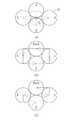
シフト機構90を用いた場合、揺動部38は、例えば図19または図20に示すシフト動作をする。図19において、揺動部38は、(a)の初期位置から90°左方向に√3/4P分シフトされ、(b)に示す一回シフトの位置に移動される。そして、(b)の一回シフトの位置での撮影が終了した後、初期位置に戻されてから90°下方向に1/4P分シフトされ、(c)に示す二回シフトの位置に移動される。揺動部38は、二回シフトの位置から初期位置に戻された後に、順次右方向((d)の三回シフトの位置、角度、シフト量は、一回シフトの場合と同様)、上方向((e)の四回シフトの位置、角度、シフト量は、二回シフトの場合と同様)にシフトされ、再び(a)の初期位置に戻される。イメージガイド31の入射端におけるコア50は、初期位置に戻るのと(b)〜(e)のシフト動作を繰り返すことで、図21(a)に示す十字状の移動軌跡を辿る。 When the shift mechanism 90 is used, the swinging portion 38 performs a shift operation shown in FIG. 19 or FIG. In FIG. 19, the swinging portion 38 is shifted by √3 / 4P to the left by 90 ° from the initial position of (a), and moved to the position of one shift shown in (b). (B) After shooting at the one-shift position is completed, after returning to the initial position, it is shifted by 90 ° downward by 1/4 P and moved to the two-shift position shown in (c). Is done. After the swinging portion 38 is returned from the double shift position to the initial position, the swing portion 38 is sequentially moved in the right direction (the position, angle, and shift amount of the three shifts in (d) are the same as in the case of the single shift), up The position is shifted in the direction (the position, angle and shift amount of the four-time shift in (e) are the same as in the case of the two-time shift), and returned to the initial position in (a) again. The core 50 at the incident end of the
あるいは図20において、揺動部38は、(a)の初期位置から90°左方向に√3/4P分シフトされた後、90°下方向に1/4P分シフトされ、(b)に示す一回シフトの位置に移動される。そして、(b)の一回シフトの位置での撮影が終了した後、一回シフトの位置から90°下方向に1/4P分シフトされた後、右方向に√3/4P分シフトされ、(c)に示す二回シフトの位置に移動される。揺動部38は、順次右および上方向((d)の三回シフトの位置、角度、シフト量は、一回シフトの場合と同様)、上および左方向(角度、シフト量は、二回シフトの場合と同様)にシフトされ、再び(a)の初期位置に戻される。コア50は、初期位置に戻るのと(a)〜(d)のシフト動作を繰り返すことで、図21(b)に示す矩形状の移動軌跡を辿る。 Alternatively, in FIG. 20, the swinging portion 38 is shifted by √3 / 4P to the left by 90 ° from the initial position of (a), and then shifted by ¼P by 90 ° downward, as shown in (b). It is moved to the shift position once. (B) After shooting at the one-shift position is completed, the image is shifted 90 ° downward from the single-shift position by ¼ P and then shifted right by √3 / 4P. It is moved to the double shift position shown in (c). The oscillating portion 38 sequentially moves in the right and upward directions (the position, angle, and shift amount of the three-time shift in (d) are the same as in the case of one-time shift), and in the upward and left directions (angle and shift amount are twice. (Similar to the case of the shift), and is returned to the initial position of (a) again. The core 50 traces the rectangular movement locus shown in FIG. 21B by returning to the initial position and repeating the shift operations (a) to (d).
もしくは、図21(c)に示すように、下および左方向、下および右方向、上および右方向、上および左方向と移動させ、上下方向の移動を必ず先に行うようにし、略卍状の移動軌跡を辿らせてもよい。いずれも移動軌跡は異なるが、上記実施形態と同様、初期位置だけでは画像化されないクラッド51の部分を埋めるように移動される。 Alternatively, as shown in FIG. 21 (c), the movement is made downward and leftward, downward and rightward, upward and rightward, upward and leftward, and the vertical movement is always performed first. The movement trajectory may be followed. In both cases, the movement trajectory is different, but as in the above-described embodiment, the movement trajectory is moved so as to fill the portion of the clad 51 that is not imaged only at the initial position.
上記実施形態の円柱状のシフト機構32は、圧電素子35を円筒状に成膜することで、シフト機構32の外径を鏡筒33の外径と略同じにすることができ、挿入部13の極細径化に寄与することができる。対して図17や図18に示す四角柱状のシフト機構90は、四隅が鏡筒33の外径から若干はみ出るために、シフト機構32と比べて挿入部13の径は大きくなるが、圧電素子92を短冊状に成膜または接着して配置することに製造上の困難性はないため、安価且つ簡単に製造することが可能である。 In the
図19〜図21で示した、90°でシフトさせる例は、上記実施形態の円柱状のシフト機構32でも実施することができる。また、図17の符号98は、治療用レーザ光を患部に照射するための光ファイバの出射端が覗いたレーザ光照射部であり、鉗子チャンネル46に代わる他の例として挙げている。勿論、シフト機構32にレーザ光照射部98を設けてもよい。 The example of shifting by 90 ° shown in FIGS. 19 to 21 can also be implemented by the
以上、シフト機構の構成やそのシフト方法の例を列挙したが、ここで挙げた例は一例に過ぎず、特にシフト方法には様々な変形例が考えられる。例えば四回シフトの三回シフトの位置を飛ばして、シフト機構を30°の方向に三回シフトさせた後、初期位置に戻してもよいし、九回シフトの八回シフトの位置を飛ばして八回シフトとしても可である。あるいは、九回シフトの一回、二回シフトをさせた後、初期位置に戻してもよい。 As mentioned above, although the structure of the shift mechanism and the example of the shift method were enumerated, the example given here is only an example, and various modifications can be considered especially in the shift method. For example, after shifting the position of the third shift of the four-time shift and shifting the shift mechanism three times in the direction of 30 °, it may be returned to the initial position, or the position of the eight-time shift of the nine-time shift may be skipped. It is also possible to shift eight times. Alternatively, after shifting once and twice nine times, the initial position may be returned.
但し、圧電素子にはヒステリシス特性があり、無秩序に駆動させるとシフト位置がずれるため、移動軌跡は毎回同じとし、常に同じ移動経路でシフト機構をシフトさせる。つまり、シフト機構をシフトさせる際の圧電素子の駆動順序を毎回同じにする。また、上下、左右で対になった電極に電圧を供給する順序も同じにする。 However, the piezoelectric element has a hysteresis characteristic, and the shift position shifts when driven in a chaotic manner. Therefore, the movement locus is the same every time, and the shift mechanism is always shifted along the same movement path. That is, the driving order of the piezoelectric elements when shifting the shift mechanism is made the same every time. In addition, the order in which the voltage is supplied to the paired electrodes on the top and bottom and the left and right is also made the same.
上記実施形態では、圧電素子駆動回路61により圧電素子35への供給電圧を制御し、イメージガイド31をシフト位置に停止させているが、これに代えて、あるいは加えて、機械的な構成でシフト機構32をシフト位置に停止させてもよい。例えば図22に示すシフト機構100(シフトの仕方はシフト機構32と同じ)のように、先端外周面のシフト方向にあたる位置に突起101を設け、シフト機構100が収まる先端部20の基体の、突起101に対向する位置に凹部102を設ける。突起101と凹部102とは、シフト機構100のシフト量分離れており、シフト機構100がシフトされたときに、突起101が凹部102に嵌まってシフト機構100が停止される。 In the above embodiment, the voltage supplied to the
あるいは図23に示すように、先端部20の基体の内壁に突起103を設けてもよい。突起103は、シフト機構32が各シフト位置に移動したときに、シフト機構32の外周面に二点(黒丸で示す)で接触する位置に設けられている。符号104は、シフト機構32の各シフト位置への移動を許すための逃がし用凹部である。シフト機構に突起を設ける必要がない分、図22の例よりも製造コストが安く済む。 Or as shown in FIG. 23, you may provide the processus |
イメージガイドの入射端をシフトさせる場合、レンズ等の結像系光学部材を動かす場合と異なり、固定部から先のイメージガイドの一部分を揺動させるので、シフト動作によってイメージガイドに掛かる力には、圧電素子によって加えられる力と元の位置に戻ろうとする反力とがある。イメージガイドの慣性質量は比較的重いため、特に反力によってイメージガイドの移動がスムーズにいかなくなることが考えられるが、図22の如く機械的にシフト位置に停止させる構成を採用することで、イメージガイドのシフト位置がずれることがなくなり、より安定した高速なシフト動作を実現することができる。また、ある程度アバウトな電圧制御でよくなる。 When shifting the incident end of the image guide, unlike the case of moving the imaging system optical member such as a lens, the part of the image guide from the fixed portion is swung, so the force applied to the image guide by the shift operation is There are a force applied by the piezoelectric element and a reaction force to return to the original position. Since the inertial mass of the image guide is relatively heavy, it is conceivable that the image guide will not move smoothly due to the reaction force in particular. However, by adopting a configuration in which the image guide is mechanically stopped at the shift position as shown in FIG. The shift position of the guide is not shifted, and a more stable and high speed shift operation can be realized. Moreover, voltage control that is about to some extent is sufficient.
先端部は使用中体内に挿入され、使用後は洗浄、消毒、あるいは滅菌されるため、高湿度環境下に置かれることが多い。そこで、配線ケーブルを含むシフト機構全体に対して防湿コーティングを行った後、先端部に組み込むことが好ましい。防湿コーティングとしては、例えば低真空、低温度の化学気相成長で均一なコーティングが可能なパリレンコートを実施する。 The tip is inserted into the body during use and is often washed, disinfected, or sterilized after use, and thus is often placed in a high humidity environment. Therefore, it is preferable that after the moisture-proof coating is applied to the entire shift mechanism including the wiring cable, it is incorporated into the tip portion. As the moisture-proof coating, for example, a parylene coating capable of uniform coating by chemical vapor deposition at low vacuum and low temperature is performed.
イメージガイドは揺動部が根元から撓ることでシフトをするので、各シフト位置にすぐには停止せず、しばらく振動してから止まる可能性がある。このため、シフト機構の停止後、シフト方向とは逆方向に瞬間的に揺動部が振れるように、圧電素子駆動回路で圧電素子を駆動する等の制振対策を講じることが好ましい。具体的には、反力をシミュレーションや実測で求めて、これを打ち消すための圧電素子の駆動電圧をROMに記憶させておき、圧電素子制御部がその駆動電圧の情報をROMから読み出して圧電素子駆動回路に与える。あるいは、空洞に絶縁性の粘性流体を封入してダンピング効果を利用し、制振対策を講じてもよい。 Since the image guide shifts when the swinging portion is bent from the base, there is a possibility that the image guide does not stop immediately at each shift position but stops after vibrating for a while. For this reason, after stopping the shift mechanism, it is preferable to take a vibration suppression measure such as driving the piezoelectric element with a piezoelectric element drive circuit so that the swinging part instantaneously swings in the direction opposite to the shift direction. Specifically, the reaction force is obtained by simulation or actual measurement, and the drive voltage of the piezoelectric element for canceling the reaction force is stored in the ROM, and the piezoelectric element control unit reads the drive voltage information from the ROM and outputs the piezoelectric element. Give to the drive circuit. Alternatively, an insulating viscous fluid may be sealed in the cavity and a damping effect may be used to take a vibration suppression measure.
上記実施形態では、揺動部が次回のシフト位置に移動するまでの時間が、CCDが前回の電荷蓄積を終えてから次回の電荷蓄積を開始するまでの時間よりも短いと説明しているが、揺動部の長さ、材質、あるいはシフト量、さらには圧電素子自体の性能等が要因で、前者の時間が後者の時間よりも長くなることもあり得る。前述のようにイメージガイドの慣性質量が比較的重いことから、前者の時間が後者の時間よりも長くなる可能性が高い。 In the above-described embodiment, it is described that the time until the swinging unit moves to the next shift position is shorter than the time from when the CCD finishes the previous charge accumulation until the next charge accumulation starts. The former time may be longer than the latter time due to factors such as the length, material, or shift amount of the oscillating portion and the performance of the piezoelectric element itself. As described above, since the inertial mass of the image guide is relatively heavy, the former time is likely to be longer than the latter time.
こうした場合には、揺動部がシフト位置に移動している間は、プロセッサ装置のCPUの制御の下、CCD駆動回路からCCDに電子シャッタパルスを供給して電荷蓄積を開始する時間を遅らせ、揺動部がシフト位置に停止してから電荷蓄積を開始する。あるいは、揺動部がシフト位置に移動している間は光源を消灯し、揺動部がシフト位置に停止したら光源を点灯する。 In such a case, while the oscillating unit is moved to the shift position, under the control of the CPU of the processor device, the electronic shutter pulse is supplied from the CCD driving circuit to the CCD to delay the time for starting the charge accumulation, Charge accumulation starts after the rocking portion stops at the shift position. Alternatively, the light source is turned off while the swinging portion is moved to the shift position, and the light source is turned on when the swinging portion is stopped at the shift position.
揺動部が次回のシフト位置に移動するまでの時間を基準にしてCCDを駆動しようとすると、前者の時間が後者の時間よりも長くなる場合はフレームレートを落とさなければならないが、電子シャッタパルスで電荷を掃き出すか、光源を点消灯させる上記いずれかの方法を採用すれば、フレームレートは現行を維持しつつブレのない画像を得ることができる。 If it is attempted to drive the CCD based on the time until the swing unit moves to the next shift position, if the former time is longer than the latter time, the frame rate must be reduced. If any one of the above-described methods of sweeping out the electric charge or turning off the light source is employed, a blur-free image can be obtained while maintaining the current frame rate.
上記実施形態では、シフト撮影モードが選択されたときのみ画像合成部で画像合成処理をしているが、通常撮影モード時にも画像合成処理をしてもよい。クラッドの位置に対応する被観察部位の像を反映した画像は得られないが、クラッドの影は埋めることができる。 In the above embodiment, the image composition processing is performed by the image composition unit only when the shift photographing mode is selected. However, the image composition processing may be performed even in the normal photographing mode. Although an image reflecting the image of the observed region corresponding to the position of the clad cannot be obtained, the shadow of the clad can be filled.
上記実施形態では、シフトの一周期毎に画像合成部で画像合成処理を行い、一つの合成画像を出力しているが、この方法であると通常撮影モードに比べてフレームレートが落ちる。このフレームレート低下の対策としては、四回シフトの場合は通常撮影モードの四倍といったように、シフト撮影モードが選択されたときにフレームレートを上げることが考えられる。 In the above embodiment, the image composition processing is performed by the image composition unit for each cycle of the shift, and one composite image is output. However, this method has a lower frame rate than the normal shooting mode. As a countermeasure for this frame rate decrease, it is conceivable to increase the frame rate when the shift shooting mode is selected, such as four times the normal shooting mode in the case of four shifts.
具体的には、CPU62のシステムクロックのクロック信号の周期を変化させることで、CCD駆動回路60の駆動信号の周期を変化させる。あるいは、システムクロックのクロック信号は変化させずに、CCD駆動回路60に分周器を設け、この分周器でシステムクロックのクロック信号を分周することで変化させてもよい。 Specifically, the cycle of the drive signal of the
三板式CCD、モード切り替えとシフト回数の設定をする操作部、および画像合成部と同期制御部と圧電素子制御部の機能を実現するハードウェアを、プロセッサ装置とは別の筐体に搭載してもよいし、内視鏡に搭載してもよい。 A three-panel CCD, an operation unit that switches modes and sets the number of shifts, and hardware that implements the functions of the image composition unit, synchronization control unit, and piezoelectric element control unit are mounted in a separate housing from the processor unit. Alternatively, it may be mounted on an endoscope.
例えば図24、25に示す内視鏡システム110のように、プロセッサ装置111とは別に中継ボックス112を設ける。なお、上記実施形態と同様の機能には同じ符号を付し、説明を省略する。 For example, a relay box 112 is provided separately from the processor device 111 as in an endoscope system 110 shown in FIGS. In addition, the same code | symbol is attached | subjected to the function similar to the said embodiment, and description is abbreviate | omitted.
図24において、中継ボックス112には、内視鏡10のプロセッサ用コネクタ15が接続されている。そして、プロセッサ装置111と中継ボックス112とは、中継ケーブル113で互いに接続されている。中継ボックス112の前面パネルには、モード切り替えとシフト回数の設定をする操作部114が設けられている。 In FIG. 24, the
図25において、中継ボックス112は、三板式CCD56、AFE59、CCD駆動回路60、圧電素子駆動回路61、CPU115、画像合成部116、およびROM117を有する。CPU115は、中継ケーブル113を介してプロセッサ装置111のCPU62と通信する。CPU115は、上記実施形態のCPU62と同様に、CCD駆動回路60、圧電素子駆動回路61の駆動制御を行い、同期制御部、圧電素子制御部の各機能を担う。画像合成部116は、シフト撮影モードが操作部114で選択された場合に、CPU115の制御の下、上記実施形態の画像合成部65aと同じ画像合成処理をAFE59からの撮像信号に対して施す。ROM117には、上記実施形態のROM63と同様、シフト情報85が記憶されている。画像合成部116で生成された合成画像は、中継ケーブル113を経由してプロセッサ装置111のDSP65に入力される。 25, the relay box 112 includes a three-
CCD等のイメージセンサを先端部に配置した電子内視鏡と汎用プロセッサ装置のシステムに本発明を適用した場合、上記実施形態ではシフト動作および画像合成に関わる機能を汎用プロセッサ装置に追加する必要があり、汎用プロセッサ装置の改造は必須となる。あるいは、汎用プロセッサ装置に代えて上記実施形態のプロセッサ装置11を新たに購入しなければならない。対して、図24および図25に示す中継ボックス112を用いれば、汎用プロセッサ装置(プロセッサ装置111)を流用することができ、設備投資費用も中継ボックス112の分だけで済むので、病院側の費用負担が減り、本発明の内視鏡システムの病院への導入障壁も低くなる。 When the present invention is applied to a system of an electronic endoscope and a general-purpose processor device in which an image sensor such as a CCD is arranged at the tip, in the above embodiment, it is necessary to add functions related to shift operation and image composition to the general-purpose processor device. Yes, general-purpose processor devices must be modified. Alternatively, the
また、図26に示す内視鏡システム120の光源装置121を用いてもよい。光源装置121は、中心波長445nmの青色レーザ光源122と、青色レーザ光源122からのレーザ光を平行光化するコリメータレンズ123と、レーザ光を集光する集光レンズ124とを有する。CPU74は、光源ドライバ71を経由して青色レーザ光源122の動作制御を行う。 Moreover, you may use the light source device 121 of the endoscope system 120 shown in FIG. The light source device 121 includes a blue
青色レーザ光源122からのレーザ光は、集光レンズ124によりライトガイド27の入射端に入射される。ライトガイド27は、入射されたレーザ光を、内視鏡10の先端部20まで伝搬する。 Laser light from the blue
一方、ライトガイド27の光出射側には、波長変換部材125が配置されている。波長変換部材125は、複数種の蛍光物質を分散配置して一体に形成された一塊のブロックである。波長変換部材125は、青色レーザ光源122からのレーザ光の一部を吸収して、緑色〜黄色に励起発光する複数種の蛍光体を有する。これにより、青色レーザ光源122からのレーザ光と、このレーザ光から変換された緑色〜黄色の励起光とが合波されて、白色光が生成される。 On the other hand, a wavelength conversion member 125 is disposed on the light exit side of the
青色レーザ光源122と波長変換部材125とで、上記実施形態と比べて高輝度な白色光を供給するので、僅かな本数(一、二本)のライトガイドで十分な照明光を得ることができる。従って、極細径化をさらに促進することができる。 Since the blue
なお、イメージセンサとしては、単板式を用いてもよい。また、上記実施形態では、イメージガイドと配線ケーブルのプロセッサ装置への接続を同じコネクタで果たしているが、イメージガイドと配線ケーブルを別のコネクタに実装してもよい。 Note that a single plate type may be used as the image sensor. In the above embodiment, the image guide and the wiring cable are connected to the processor device by the same connector. However, the image guide and the wiring cable may be mounted on different connectors.
2、110、120 内視鏡システム
10 内視鏡
11、111 プロセッサ装置
12、121 光源装置
13 挿入部
20 先端部
27 ライトガイド
31 イメージガイド
32、90、100 シフト機構
34、91 保持筒
35、92 圧電素子
36、93 電極
38 揺動部
39 固定部
43 幅狭部
45 配線ケーブル
56 三板式CCD
58R、58G、58B CCD
60 CCD駆動回路
61 圧電素子駆動回路
62 CPU
62a 同期制御部
62b 圧電素子制御部
63、117 ROM
65 デジタル信号処理回路(DSP)
65a、116 画像合成部
65b 二値化処理部
65c 中心座標検出部
65d 内部メモリ
68、114 操作部
80 像
81 画素
85 シフト情報
86 結像領域
101、103 突起
102 凹部
112 中継ボックス
115 CPU
122 青色レーザ光源
125 波長変換部材2, 110, 120
58R, 58G, 58B CCD
60
62a
65 Digital signal processing circuit (DSP)
65a, 116 Image composition unit 65b Binarization processing unit 65c Center coordinate detection unit
122 Blue laser light source 125 Wavelength conversion member
Claims (18)
Translated fromJapanese前記イメージガイドで伝達された像を撮像するイメージセンサと、
対物光学系で結像された像に対して前記イメージガイドの入射端を周期的にシフト動作させるシフト機構と、
前記シフト機構によるシフト動作に同期して前記イメージセンサに複数回撮像させ、対物光学系で結像された像に対する前記イメージガイドの入射端の位置が異なる状態で撮像された複数の画像が得られるよう、前記イメージセンサと前記シフト機構の動作を制御する同期制御手段と、
前記イメージガイドの各光ファイバで伝達された像と前記イメージセンサの画素の撮像面上の位置関係、および前記シフト機構でシフトされる前記イメージガイドのシフト量の情報に基づき、得られた複数の画像を合成して、一つの合成画像を生成する画像合成手段とを備えることを特徴とする内視鏡システム。An image guide formed by bundling a plurality of optical fibers, and an image guide that is inserted through an insertion portion of an endoscope and that transmits an image of an observation site that is imaged at an entrance end by an objective optical system to an exit end; ,
An image sensor that captures an image transmitted by the image guide;
A shift mechanism that periodically shifts the incident end of the image guide with respect to an image formed by the objective optical system;
In synchronization with the shift operation by the shift mechanism, the image sensor captures a plurality of images, and a plurality of images captured with different positions of the incident end of the image guide with respect to the image formed by the objective optical system are obtained. A synchronization control means for controlling the operation of the image sensor and the shift mechanism;
Based on the positional relationship on the imaging surface of the image sensor pixels and the image transmitted by each optical fiber of the image guide, and information on the shift amount of the image guide shifted by the shift mechanism, a plurality of obtained information An endoscope system comprising: an image synthesis means for synthesizing images and generating one synthesized image.
生成されたマスク画像に基づいて、前記イメージセンサの撮像面上における、各光ファイバで伝達された像の中心位置を検出する位置検出手段とからなることを特徴とする請求項2または3に記載の内視鏡システム。The information acquisition means includes: binarization processing means for performing a binarization process on a reference image to generate a mask image;
The position detection means which detects the center position of the image transmitted with each optical fiber on the imaging surface of the said image sensor based on the produced | generated mask image is characterized by the above-mentioned. Endoscope system.
各結像領域内における前記イメージセンサの画素の画素値に基づいて、各結像領域の画素値の代表値を算出することを特徴とする請求項4に記載の内視鏡システム。The image synthesizing unit sets an imaging region centered on the center position detected by the position detecting unit and having a core diameter of the optical fiber as a diameter for each optical fiber,
The endoscope system according to claim 4, wherein a representative value of the pixel value of each imaging region is calculated based on a pixel value of a pixel of the image sensor in each imaging region.
前記イメージセンサは、各位置でその都度撮像することを特徴とする請求項1ないし10のいずれかに記載の内視鏡システム。The shift mechanism moves the incident end of the image guide from the first position to the second position, from the second position to the third position in order, and finally returns to the first position for one cycle. Shift operation,
The endoscope system according to claim 1, wherein the image sensor picks up an image at each position.
前記保持筒の外周面には前記圧電素子が形成され、前記圧電素子の駆動力が前記保持筒を介して前記イメージガイドに伝えられることを特徴とする請求項1ないし15のいずれかに記載の内視鏡システム。The shift mechanism has a holding cylinder in which the incident end of the image guide is inserted and fixed, and holds the incident end of the image guide in a shiftable state,
The piezoelectric element is formed on an outer peripheral surface of the holding cylinder, and a driving force of the piezoelectric element is transmitted to the image guide through the holding cylinder. Endoscope system.
前記イメージガイドの入射端の外周に形成された圧電素子で前記イメージガイドの入射端を揺動させ、対物光学系で結像された像に対して前記イメージガイドの入射端を周期的にシフト動作させるシフト機構とを備え、
前記シフト機構によるシフト動作に同期してイメージセンサに複数回撮像させ、対物光学系で結像された像に対する前記イメージガイドの入射端の位置が異なる状態で撮像された複数の画像が得られるよう、前記イメージセンサと前記シフト機構の動作が制御され、前記イメージガイドの各光ファイバで伝達された像と前記イメージセンサの画素の撮像面上の位置関係、および前記シフト機構でシフトされる前記イメージガイドのシフト量の情報に基づき、得られた複数の画像を合成して、一つの合成画像が生成されることを特徴とする内視鏡。An image guide formed by bundling a plurality of optical fibers, an image guide that is inserted into an insertion portion and transmits an image of an observed site imaged at an entrance end by an objective optical system to an exit end;
The incident end of the image guide is swung by a piezoelectric element formed on the outer periphery of the incident end of the image guide, and the incident end of the image guide is periodically shifted with respect to the image formed by the objective optical system. And a shift mechanism
Synchronizing with the shift operation by the shift mechanism, the image sensor can capture images a plurality of times so that a plurality of images captured with different positions of the incident end of the image guide with respect to the image formed by the objective optical system can be obtained. The operation of the image sensor and the shift mechanism is controlled, the positional relationship between the image transmitted by each optical fiber of the image guide and the image sensor pixels on the imaging surface, and the image shifted by the shift mechanism An endoscope, wherein a plurality of obtained images are synthesized based on information on a guide shift amount to generate a single synthesized image.
シフト動作に同期してイメージセンサに複数回撮像させるステップと、
イメージガイドの各光ファイバで伝達された像とイメージセンサの画素の撮像面上の位置関係、およびシフト機構でシフトされるイメージガイドのシフト量の情報に基づき、複数回の撮像により得られた、対物光学系で結像された像に対するイメージガイドの入射端の位置が異なる状態で撮像された複数の画像を合成して、画像合成手段で一つの合成画像を生成するステップとを備えることを特徴とする内視鏡駆動方法。This is an image guide formed by bundling a plurality of optical fibers, and is an image guide that is inserted into an insertion portion of an endoscope and transmits an image of a site to be observed imaged at an entrance end by an objective optical system to an exit end. Oscillating the incident end with a piezoelectric element formed on the outer periphery thereof, and periodically shifting the incident end of the image guide with respect to the image formed by the objective optical system;
A step of causing the image sensor to image a plurality of times in synchronization with the shift operation;
Based on the positional relationship on the imaging surface of the image of the image sensor pixels and the image sensor pixels, and the amount of shift of the image guide shifted by the shift mechanism, obtained by multiple imaging, Synthesizing a plurality of images picked up with different positions of the incident end of the image guide with respect to the image formed by the objective optical system, and generating a single combined image by the image combining means. Endoscope driving method.
Priority Applications (3)
| Application Number | Priority Date | Filing Date | Title |
|---|---|---|---|
| JP2009108983AJP2010253156A (en) | 2009-04-28 | 2009-04-28 | Endoscope system, endoscope, and endoscope driving method |
| US12/768,463US20100274082A1 (en) | 2009-04-28 | 2010-04-27 | Endoscope system, endoscope, and driving method |
| EP10161275AEP2245978A1 (en) | 2009-04-28 | 2010-04-28 | Endoscope system, endoscope, and driving method |
Applications Claiming Priority (1)
| Application Number | Priority Date | Filing Date | Title |
|---|---|---|---|
| JP2009108983AJP2010253156A (en) | 2009-04-28 | 2009-04-28 | Endoscope system, endoscope, and endoscope driving method |
Publications (1)
| Publication Number | Publication Date |
|---|---|
| JP2010253156Atrue JP2010253156A (en) | 2010-11-11 |
Family
ID=42270180
Family Applications (1)
| Application Number | Title | Priority Date | Filing Date |
|---|---|---|---|
| JP2009108983AAbandonedJP2010253156A (en) | 2009-04-28 | 2009-04-28 | Endoscope system, endoscope, and endoscope driving method |
Country Status (3)
| Country | Link |
|---|---|
| US (1) | US20100274082A1 (en) |
| EP (1) | EP2245978A1 (en) |
| JP (1) | JP2010253156A (en) |
Cited By (5)
| Publication number | Priority date | Publication date | Assignee | Title |
|---|---|---|---|---|
| CN102578988A (en)* | 2011-01-05 | 2012-07-18 | 奥林巴斯株式会社 | Endoscopic image reproducing apparatus |
| JP2013192063A (en)* | 2012-03-14 | 2013-09-26 | Hitachi-Ge Nuclear Energy Ltd | Image processing method and image processor |
| WO2014103879A1 (en)* | 2012-12-26 | 2014-07-03 | オリンパスメディカルシステムズ株式会社 | Image recording device and image recording method |
| JP2017524505A (en)* | 2014-07-24 | 2017-08-31 | ゼット スクエア リミテッド | Multi-core fiber endoscope |
| US10398294B2 (en) | 2014-07-24 | 2019-09-03 | Z Square Ltd. | Illumination sources for multicore fiber endoscopes |
Families Citing this family (19)
| Publication number | Priority date | Publication date | Assignee | Title |
|---|---|---|---|---|
| US10588486B2 (en)* | 2013-09-19 | 2020-03-17 | Physio-Control, Inc | Multi-function video system with interchangeable medical tool |
| EP2661211B1 (en)* | 2011-01-05 | 2022-03-30 | Bar-Ilan University | Imaging system and method using multicore fiber |
| US9801551B2 (en)* | 2012-07-20 | 2017-10-31 | Intuitive Sugical Operations, Inc. | Annular vision system |
| MX389501B (en) | 2012-07-26 | 2025-03-20 | Depuy Synthes Products Inc | CONTINUOUS VIDEO IN A LIGHT-POOR ENVIRONMENT |
| MX346174B (en)* | 2012-07-26 | 2017-03-10 | Depuy Synthes Products Inc | YCBCR PULSED LIGHTING SCHEME IN A DEFICIENT LIGHT ENVIRONMENT. |
| EP2789289B1 (en)* | 2012-10-11 | 2016-09-07 | Olympus Corporation | Endoscope device and treatment device |
| US20150374210A1 (en)* | 2013-03-13 | 2015-12-31 | Massachusetts Institute Of Technology | Photometric stereo endoscopy |
| WO2014145249A1 (en) | 2013-03-15 | 2014-09-18 | Olive Medical Corporation | Controlling the integral light energy of a laser pulse |
| WO2014144947A1 (en) | 2013-03-15 | 2014-09-18 | Olive Medical Corporation | Super resolution and color motion artifact correction in a pulsed color imaging system |
| CA2906821A1 (en) | 2013-03-15 | 2014-09-18 | Olive Medical Corporation | Scope sensing in a light controlled environment |
| JP5931031B2 (en)* | 2013-09-23 | 2016-06-08 | 富士フイルム株式会社 | Endoscope system and method for operating endoscope system |
| WO2015143453A1 (en) | 2014-03-21 | 2015-09-24 | Olive Medical Corporation | Card edge connector for an imaging sensor |
| FR3019625B1 (en)* | 2014-04-04 | 2018-10-26 | Maquet Sas | OPERATIVE LIGHTING APPARATUS WITH LASER SOURCE DEPORTEE |
| JP5959788B1 (en)* | 2014-11-20 | 2016-08-02 | オリンパス株式会社 | Scanning endoscope |
| KR102186742B1 (en)* | 2015-06-25 | 2020-12-04 | 인더스마트 주식회사 | Multi image processing apparatus and multi image processing method of android system for high speed and short distance interface |
| US10426327B2 (en)* | 2015-11-02 | 2019-10-01 | Buffalo Filter Llc | Fluid filtration, cleaning, and defogging device |
| US11166628B2 (en) | 2016-02-02 | 2021-11-09 | Physio-Control, Inc. | Laryngoscope with handle-grip activated recording |
| CN113570520B (en) | 2021-07-28 | 2024-09-20 | 苏州微景医学科技有限公司 | Optical fiber image correction method, device and computer readable storage medium |
| CN116584874B (en)* | 2023-04-03 | 2024-12-06 | 无锡海斯凯尔医学技术有限公司 | Optical fiber image real-time correction method, device, storage medium, and electronic device |
Citations (5)
| Publication number | Priority date | Publication date | Assignee | Title |
|---|---|---|---|---|
| JPS63265215A (en)* | 1987-04-23 | 1988-11-01 | Olympus Optical Co Ltd | Endoscope device |
| JPH04138127A (en)* | 1990-09-28 | 1992-05-12 | Olympus Optical Co Ltd | Mesh image alleviation device for endoscope |
| JPH08191440A (en)* | 1995-01-10 | 1996-07-23 | Fukuda Denshi Co Ltd | Endoscopic image correction method and device |
| JP2003525462A (en)* | 2000-01-07 | 2003-08-26 | インスティテュート・フュール・ミクロテヒニーク・マインツ・ゲゼルシャフト・ミット・ベシュレンクテル・ハフツング | Optical fiber switching element |
| JP2007516760A (en)* | 2003-12-31 | 2007-06-28 | マウナ ケア テクノロジーズ | Super-resolution method and apparatus for confocal images acquired through an image guide, and apparatus for carrying out this method |
Family Cites Families (43)
| Publication number | Priority date | Publication date | Assignee | Title |
|---|---|---|---|---|
| JPS6053919A (en) | 1983-09-05 | 1985-03-28 | Olympus Optical Co Ltd | Observing and image sensing device for endoscope |
| FR2569278B1 (en)* | 1984-08-14 | 1988-04-08 | Thomson Csf | IMAGE TRANSPORT DEVICE BY OPTICAL CABLE |
| US4867136A (en)* | 1987-04-23 | 1989-09-19 | Olympus Optical Co., Ltd. | Endoscope apparatus |
| US5436655A (en)* | 1991-08-09 | 1995-07-25 | Olympus Optical Co., Ltd. | Endoscope apparatus for three dimensional measurement for scanning spot light to execute three dimensional measurement |
| US5281960A (en)* | 1991-11-19 | 1994-01-25 | Silhouette Technology, Inc. | Helmet mounted display |
| JPH06343134A (en) | 1993-05-31 | 1994-12-13 | Shimadzu Corp | Fiberscope |
| US5727098A (en)* | 1994-09-07 | 1998-03-10 | Jacobson; Joseph M. | Oscillating fiber optic display and imager |
| US6563105B2 (en)* | 1999-06-08 | 2003-05-13 | University Of Washington | Image acquisition with depth enhancement |
| US6294775B1 (en)* | 1999-06-08 | 2001-09-25 | University Of Washington | Miniature image acquistion system using a scanning resonant waveguide |
| US6856712B2 (en)* | 2000-11-27 | 2005-02-15 | University Of Washington | Micro-fabricated optical waveguide for use in scanning fiber displays and scanned fiber image acquisition |
| US7616986B2 (en)* | 2001-05-07 | 2009-11-10 | University Of Washington | Optical fiber scanner for performing multimodal optical imaging |
| US6885801B1 (en)* | 2001-12-06 | 2005-04-26 | Clear Image Technology Llc | Enhancement of fiber based images |
| WO2004068218A2 (en)* | 2003-01-24 | 2004-08-12 | University Of Washington | Optical beam scanning system for compact image display or image acquisition |
| US7311723B2 (en)* | 2003-07-11 | 2007-12-25 | University Of Washington | Scanning laser device and methods of use |
| US7901348B2 (en)* | 2003-12-12 | 2011-03-08 | University Of Washington | Catheterscope 3D guidance and interface system |
| US8929688B2 (en)* | 2004-10-01 | 2015-01-06 | University Of Washington | Remapping methods to reduce distortions in images |
| US7298938B2 (en)* | 2004-10-01 | 2007-11-20 | University Of Washington | Configuration memory for a scanning beam device |
| US7159782B2 (en)* | 2004-12-23 | 2007-01-09 | University Of Washington | Methods of driving a scanning beam device to achieve high frame rates |
| US7189961B2 (en)* | 2005-02-23 | 2007-03-13 | University Of Washington | Scanning beam device with detector assembly |
| US7530948B2 (en)* | 2005-02-28 | 2009-05-12 | University Of Washington | Tethered capsule endoscope for Barrett's Esophagus screening |
| US7312879B2 (en)* | 2005-08-23 | 2007-12-25 | University Of Washington | Distance determination in a scanned beam image capture device |
| US20070213618A1 (en)* | 2006-01-17 | 2007-09-13 | University Of Washington | Scanning fiber-optic nonlinear optical imaging and spectroscopy endoscope |
| DE102006011707B4 (en)* | 2006-03-14 | 2010-11-18 | Fraunhofer-Gesellschaft zur Förderung der angewandten Forschung e.V. | Method and device for producing a structure-free fiberscopic recording |
| US20080058629A1 (en)* | 2006-08-21 | 2008-03-06 | University Of Washington | Optical fiber scope with both non-resonant illumination and resonant collection/imaging for multiple modes of operation |
| US7680373B2 (en)* | 2006-09-13 | 2010-03-16 | University Of Washington | Temperature adjustment in scanning beam devices |
| DE102006046925A1 (en)* | 2006-09-28 | 2008-04-03 | Jenlab Gmbh | Method for laser endoscopy e.g. for medical work and for semiconductor processing, requires laser pulse for producing multi-photon processes as target ionization |
| US7738762B2 (en)* | 2006-12-15 | 2010-06-15 | University Of Washington | Attaching optical fibers to actuator tubes with beads acting as spacers and adhesives |
| US7447415B2 (en)* | 2006-12-15 | 2008-11-04 | University Of Washington | Attaching optical fibers to actuator tubes with beads acting as spacers and adhesives |
| US8840566B2 (en)* | 2007-04-02 | 2014-09-23 | University Of Washington | Catheter with imaging capability acts as guidewire for cannula tools |
| US7583872B2 (en)* | 2007-04-05 | 2009-09-01 | University Of Washington | Compact scanning fiber device |
| US7813538B2 (en)* | 2007-04-17 | 2010-10-12 | University Of Washington | Shadowing pipe mosaicing algorithms with application to esophageal endoscopy |
| US7608842B2 (en)* | 2007-04-26 | 2009-10-27 | University Of Washington | Driving scanning fiber devices with variable frequency drive signals |
| US8212884B2 (en)* | 2007-05-22 | 2012-07-03 | University Of Washington | Scanning beam device having different image acquisition modes |
| US8437587B2 (en)* | 2007-07-25 | 2013-05-07 | University Of Washington | Actuating an optical fiber with a piezoelectric actuator and detecting voltages generated by the piezoelectric actuator |
| US7522813B1 (en)* | 2007-10-04 | 2009-04-21 | University Of Washington | Reducing distortion in scanning fiber devices |
| US8411922B2 (en)* | 2007-11-30 | 2013-04-02 | University Of Washington | Reducing noise in images acquired with a scanning beam device |
| US20090177042A1 (en)* | 2008-01-09 | 2009-07-09 | University Of Washington | Color image acquisition with scanning laser beam devices |
| US20090208143A1 (en)* | 2008-02-19 | 2009-08-20 | University Of Washington | Efficient automated urothelial imaging using an endoscope with tip bending |
| JP2009240621A (en)* | 2008-03-31 | 2009-10-22 | Hoya Corp | Endoscope apparatus |
| JP2010253155A (en)* | 2009-04-28 | 2010-11-11 | Fujifilm Corp | Endoscope system, endoscope, and endoscope driving method |
| JP2010284369A (en)* | 2009-06-12 | 2010-12-24 | Fujifilm Corp | Endoscope system, endoscope, and endoscope driving method |
| JP5340089B2 (en)* | 2009-09-08 | 2013-11-13 | 富士フイルム株式会社 | Endoscope |
| JP2011045525A (en)* | 2009-08-27 | 2011-03-10 | Fujifilm Corp | Endoscope |
- 2009
- 2009-04-28JPJP2009108983Apatent/JP2010253156A/ennot_activeAbandoned
- 2010
- 2010-04-27USUS12/768,463patent/US20100274082A1/ennot_activeAbandoned
- 2010-04-28EPEP10161275Apatent/EP2245978A1/ennot_activeWithdrawn
Patent Citations (5)
| Publication number | Priority date | Publication date | Assignee | Title |
|---|---|---|---|---|
| JPS63265215A (en)* | 1987-04-23 | 1988-11-01 | Olympus Optical Co Ltd | Endoscope device |
| JPH04138127A (en)* | 1990-09-28 | 1992-05-12 | Olympus Optical Co Ltd | Mesh image alleviation device for endoscope |
| JPH08191440A (en)* | 1995-01-10 | 1996-07-23 | Fukuda Denshi Co Ltd | Endoscopic image correction method and device |
| JP2003525462A (en)* | 2000-01-07 | 2003-08-26 | インスティテュート・フュール・ミクロテヒニーク・マインツ・ゲゼルシャフト・ミット・ベシュレンクテル・ハフツング | Optical fiber switching element |
| JP2007516760A (en)* | 2003-12-31 | 2007-06-28 | マウナ ケア テクノロジーズ | Super-resolution method and apparatus for confocal images acquired through an image guide, and apparatus for carrying out this method |
Cited By (8)
| Publication number | Priority date | Publication date | Assignee | Title |
|---|---|---|---|---|
| CN102578988A (en)* | 2011-01-05 | 2012-07-18 | 奥林巴斯株式会社 | Endoscopic image reproducing apparatus |
| CN102578988B (en)* | 2011-01-05 | 2014-09-24 | 奥林巴斯株式会社 | Endoscopic image reproducing apparatus |
| JP2013192063A (en)* | 2012-03-14 | 2013-09-26 | Hitachi-Ge Nuclear Energy Ltd | Image processing method and image processor |
| WO2014103879A1 (en)* | 2012-12-26 | 2014-07-03 | オリンパスメディカルシステムズ株式会社 | Image recording device and image recording method |
| JP5690450B2 (en)* | 2012-12-26 | 2015-03-25 | オリンパスメディカルシステムズ株式会社 | Image recording device |
| US10426322B2 (en) | 2012-12-26 | 2019-10-01 | Olympus Corporation | Image recording apparatus |
| JP2017524505A (en)* | 2014-07-24 | 2017-08-31 | ゼット スクエア リミテッド | Multi-core fiber endoscope |
| US10398294B2 (en) | 2014-07-24 | 2019-09-03 | Z Square Ltd. | Illumination sources for multicore fiber endoscopes |
Also Published As
| Publication number | Publication date |
|---|---|
| US20100274082A1 (en) | 2010-10-28 |
| EP2245978A1 (en) | 2010-11-03 |
Similar Documents
| Publication | Publication Date | Title |
|---|---|---|
| JP2010253156A (en) | Endoscope system, endoscope, and endoscope driving method | |
| JP2010284369A (en) | Endoscope system, endoscope, and endoscope driving method | |
| JP2010253155A (en) | Endoscope system, endoscope, and endoscope driving method | |
| JP5340089B2 (en) | Endoscope | |
| JP2011045525A (en) | Endoscope | |
| CN103260499B (en) | camera device | |
| US8643710B2 (en) | Image pickup apparatus | |
| JP5317893B2 (en) | Endoscope system | |
| JP6401800B2 (en) | Image processing apparatus, operation method of image processing apparatus, operation program for image processing apparatus, and endoscope apparatus | |
| JP5145299B2 (en) | Calibration method and apparatus | |
| JP2011045461A (en) | Processor for optical scanning endoscope | |
| JP5210991B2 (en) | Calibration method and apparatus | |
| JPWO2018073959A1 (en) | Endoscope scope, endoscope processor and endoscope adapter | |
| JP6937902B2 (en) | Endoscope system | |
| JP2014183908A (en) | Imaging system | |
| JP3353949B2 (en) | Imaging system | |
| JP7068438B2 (en) | Image processing equipment, endoscope systems, image processing methods and programs | |
| JP2002136474A (en) | Endoscope | |
| JP7224963B2 (en) | Medical controller and medical observation system | |
| JP5340085B2 (en) | Endoscope | |
| JP2020141853A (en) | Image processing device, image processing method, and program | |
| JP2008136732A (en) | Three-plate electronic endoscope and electronic endoscope system | |
| JP2024179457A (en) | Image processing device and image processing system | |
| JP2025040886A (en) | Medical imaging device and medical observation system | |
| JP2020130884A (en) | Medical image processing apparatus, image processing method, and program |
Legal Events
| Date | Code | Title | Description |
|---|---|---|---|
| A621 | Written request for application examination | Free format text:JAPANESE INTERMEDIATE CODE: A621 Effective date:20111206 | |
| A131 | Notification of reasons for refusal | Free format text:JAPANESE INTERMEDIATE CODE: A131 Effective date:20121226 | |
| A521 | Request for written amendment filed | Free format text:JAPANESE INTERMEDIATE CODE: A523 Effective date:20130212 | |
| A131 | Notification of reasons for refusal | Free format text:JAPANESE INTERMEDIATE CODE: A131 Effective date:20130814 | |
| A762 | Written abandonment of application | Free format text:JAPANESE INTERMEDIATE CODE: A762 Effective date:20130927 |