JP2010250013A - Display device and light source device - Google Patents
Display device and light source deviceDownload PDFInfo
- Publication number
- JP2010250013A JP2010250013AJP2009098339AJP2009098339AJP2010250013AJP 2010250013 AJP2010250013 AJP 2010250013AJP 2009098339 AJP2009098339 AJP 2009098339AJP 2009098339 AJP2009098339 AJP 2009098339AJP 2010250013 AJP2010250013 AJP 2010250013A
- Authority
- JP
- Japan
- Prior art keywords
- light emitting
- light
- end side
- reflecting
- emitting module
- Prior art date
- Legal status (The legal status is an assumption and is not a legal conclusion. Google has not performed a legal analysis and makes no representation as to the accuracy of the status listed.)
- Ceased
Links
- 238000013459approachMethods0.000claims1
- 238000009792diffusion processMethods0.000abstractdescription30
- 239000004973liquid crystal related substanceSubstances0.000description27
- 239000011347resinSubstances0.000description10
- 229920005989resinPolymers0.000description10
- 239000010408filmSubstances0.000description9
- 238000010521absorption reactionMethods0.000description8
- 239000000758substrateSubstances0.000description8
- 239000006096absorbing agentSubstances0.000description7
- 230000003287optical effectEffects0.000description6
- 238000010586diagramMethods0.000description5
- GWEVSGVZZGPLCZ-UHFFFAOYSA-NTitan oxideChemical compoundO=[Ti]=OGWEVSGVZZGPLCZ-UHFFFAOYSA-N0.000description4
- 239000000463materialSubstances0.000description4
- 229920000139polyethylene terephthalatePolymers0.000description4
- 239000005020polyethylene terephthalateSubstances0.000description4
- 238000009825accumulationMethods0.000description3
- 239000011248coating agentSubstances0.000description3
- 238000000576coating methodMethods0.000description3
- 230000007423decreaseEffects0.000description3
- 239000011521glassSubstances0.000description3
- XEEYBQQBJWHFJM-UHFFFAOYSA-NIronChemical compound[Fe]XEEYBQQBJWHFJM-UHFFFAOYSA-N0.000description2
- OAICVXFJPJFONN-UHFFFAOYSA-NPhosphorusChemical compound[P]OAICVXFJPJFONN-UHFFFAOYSA-N0.000description2
- 238000000034methodMethods0.000description2
- -1polyethylene terephthalatePolymers0.000description2
- 238000007789sealingMethods0.000description2
- 239000004408titanium dioxideSubstances0.000description2
- 238000011144upstream manufacturingMethods0.000description2
- 239000012463white pigmentSubstances0.000description2
- FYYHWMGAXLPEAU-UHFFFAOYSA-NMagnesiumChemical compound[Mg]FYYHWMGAXLPEAU-UHFFFAOYSA-N0.000description1
- 229910052782aluminiumInorganic materials0.000description1
- XAGFODPZIPBFFR-UHFFFAOYSA-NaluminiumChemical compound[Al]XAGFODPZIPBFFR-UHFFFAOYSA-N0.000description1
- 230000000903blocking effectEffects0.000description1
- 239000012141concentrateSubstances0.000description1
- 238000002788crimpingMethods0.000description1
- 230000000694effectsEffects0.000description1
- 229910052742ironInorganic materials0.000description1
- 229910052749magnesiumInorganic materials0.000description1
- 239000011777magnesiumSubstances0.000description1
- 229910001092metal group alloyInorganic materials0.000description1
- 239000012788optical filmSubstances0.000description1
- 239000003973paintSubstances0.000description1
- 238000010422paintingMethods0.000description1
- 230000002093peripheral effectEffects0.000description1
- 239000012466permeateSubstances0.000description1
- 229920006267polyester filmPolymers0.000description1
- 230000001681protective effectEffects0.000description1
- 239000000565sealantSubstances0.000description1
- 229910000679solderInorganic materials0.000description1
- 238000005476solderingMethods0.000description1
- 125000006850spacer groupChemical group0.000description1
- 239000010409thin filmSubstances0.000description1
Images


Landscapes
- Liquid Crystal (AREA)
- Planar Illumination Modules (AREA)
Abstract
Description
Translated fromJapanese本発明は、画像表示を行う表示装置および光源装置に関する。 The present invention relates to a display device and a light source device that perform image display.
例えば液晶テレビや液晶モニタに代表される液晶表示装置などの表示装置では、表示パネルの背面から光を照射するために、バックライト装置と呼ばれる発光装置が設けられている。
この種のバックライト装置として、例えば表示パネルの直下(背面)に平面状に光源を配置する直下型と呼ばれるものが知られている。この直下型のバックライト装置は、輝度を高く確保できるという点で優れているが、光源の直上となる部位が周囲に比して明るくなりやすいため、輝度ムラが発生しやすくなる。また、混色を促進するために光源から表示パネル等の被照射物までの光路長をある程度長く確保する必要がある。そのため、直下型のバックライト装置では、装置の厚みが厚くなりやすい。For example, in a display device such as a liquid crystal display device typified by a liquid crystal television or a liquid crystal monitor, a light emitting device called a backlight device is provided to emit light from the back surface of the display panel.
As this type of backlight device, for example, a so-called direct type in which a light source is arranged in a planar shape directly under (back) a display panel is known. This direct type backlight device is excellent in that high luminance can be secured, but the portion directly above the light source is likely to be brighter than the surroundings, and thus uneven luminance tends to occur. Further, in order to promote color mixing, it is necessary to secure a long optical path length from the light source to the irradiated object such as a display panel. Therefore, in the direct type backlight device, the thickness of the device tends to be thick.
また、表示パネルの背面に導光板を設け、この導光板の二辺あるいは一辺に光源を配置し、導光板の側面側から入射させた光を導光板の裏面側に設けた反射部によって表示パネル側に反射させる所謂エッジライト型と呼ばれるバックライト装置も知られている。このエッジライト型のバックライト装置は、光源から表示パネル等の被照射物までの光路長を確保しやすいため、上述した直下型のバックライト装置と比較して、装置を薄くできるという利点がある。一方、エッジライト型のバックライト装置では、光源の取り付け位置が表示パネルの側部に限られることから、例えば40インチサイズ以上となる大型の表示装置においては、光源から遠い側において光量が低下し輝度ムラが発生しやすくなる。 In addition, a light guide plate is provided on the back surface of the display panel, a light source is disposed on two or one side of the light guide plate, and the light incident from the side surface side of the light guide plate is provided by a reflective portion provided on the back side of the light guide plate. There is also known a so-called edge light type backlight device that reflects light to the side. Since this edge light type backlight device can easily secure the optical path length from the light source to the irradiated object such as the display panel, there is an advantage that the device can be made thinner than the direct type backlight device described above. . On the other hand, in the edge-light type backlight device, the light source is attached only to the side of the display panel. For example, in a large display device having a size of 40 inches or more, the amount of light decreases on the side far from the light source. Brightness unevenness is likely to occur.
さらに、表示パネルのサイズによって導光板のサイズが決まることから、表示パネルが大きくなるほど導光板のサイズも大きくせざるを得ない。そして、導光板のサイズが大きくなるに従い、導光板の機械的な強度が低下したり、あるいは、導光板の重量が増加したりする等の新たな問題が生じてしまう。 Furthermore, since the size of the light guide plate is determined by the size of the display panel, the size of the light guide plate must be increased as the display panel becomes larger. As the size of the light guide plate increases, new problems such as a decrease in the mechanical strength of the light guide plate or an increase in the weight of the light guide plate occur.
公報記載の従来技術として、表示パネルの直下に、表示パネル面とほぼ平行な方向に光を出射する発光体と発光体から出射された光を表示パネル面側に反射する反射体とを組とする発光モジュールを光の出射方向が揃うように複数並べて配置するようにした技術が存在する(特許文献1参照)。 As a prior art described in the publication, a light emitter that emits light in a direction substantially parallel to the display panel surface and a reflector that reflects the light emitted from the light emitter toward the display panel surface are set directly below the display panel. There is a technique in which a plurality of light emitting modules are arranged side by side so that the light emission directions are aligned (see Patent Document 1).
ところで、例えば上記特許文献1のようにバックライト装置を構成した場合、発光モジュールから出射された光は主に表示パネル側に向かうが、一部の光はさらに出射方向の下流側に位置する他の発光モジュール側へと進む。すると、発光モジュールの出射方向の下流側に位置する他の発光モジュールが設けられている領域は、出射方向の下流側に設けられる他の発光モジュールから出射される光に、その上流側の発光モジュールで出射された光が加えられた状態となる。すると、出射方向下流側の光量が出射方向上流側の光量よりも増加することになってしまい、バックライト装置から出力される面状光に輝度ムラが生ずるおそれがあった。 By the way, when the backlight device is configured as in Patent Document 1, for example, the light emitted from the light emitting module is mainly directed to the display panel side, but a part of the light is further located downstream in the emission direction. Proceed to the light emitting module side. Then, the region where the other light emitting modules located on the downstream side in the emission direction of the light emitting module are provided is the light emitted from the other light emitting modules provided on the downstream side in the emission direction to the upstream light emitting module. The light emitted at is added. As a result, the amount of light on the downstream side in the emission direction increases more than the amount of light on the upstream side in the emission direction, and there is a risk of uneven brightness in the planar light output from the backlight device.
本発明は、それぞれが発光部を有する発光モジュールを複数並べて配置した光源装置等において、輝度ムラの発生を抑制することを目的とする。 An object of the present invention is to suppress the occurrence of uneven brightness in a light source device or the like in which a plurality of light emitting modules each having a light emitting unit are arranged.
本発明は、画像表示を行う表示パネルと、表示パネルの背面に設けられ表示パネルに向けて光を照射するバックライト装置とを備えた表示装置であって、バックライト装置は、一端側から他端側へと延びて展開されるフレームと、フレームに配置され、一端側から他端側へと向かう方向と交差する方向に配列される複数の発光素子を用いて一端側から他端側に向かう光を出射する第1の発光部と、第1の発光部から出射された光を表示パネル側に向けて反射する第1の反射部材とを有する第1の発光モジュールと、フレームに第1の発光モジュールの他端側と隣り合うように配置され、一端側から他端側へと向かう方向と交差する方向に配列される複数の発光素子を用いて一端側から他端側に向かう光を出射する第2の発光部と、第2の発光部から出射された光を表示パネル側に向けて反射する第2の反射部材とを有する第2の発光モジュールとを備え、第2の反射部材の他端側における第2の反射部材の表示パネルに向かう方向の高さが、第1の反射部材の他端側における第1の反射部材の表示パネルに向かう方向の高さよりも大きく設定されることを特徴としている。 The present invention is a display device that includes a display panel that displays an image, and a backlight device that is provided on the back surface of the display panel and emits light toward the display panel. A frame that extends to the end side and is deployed, and a plurality of light emitting elements that are arranged on the frame and are arranged in a direction intersecting with the direction from the one end side to the other end side, are directed from the one end side to the other end side. A first light-emitting module having a first light-emitting portion that emits light; a first reflecting member that reflects light emitted from the first light-emitting portion toward the display panel; Light emitted from one end side to the other end side is emitted using a plurality of light emitting elements that are arranged adjacent to the other end side of the light emitting module and are arranged in a direction crossing the direction from the one end side to the other end side. Second light emitting unit and second light emission And a second light emitting module having a second reflecting member that reflects the light emitted from the second reflecting member toward the display panel, and the display panel of the second reflecting member on the other end side of the second reflecting member. The height in the direction toward is set to be larger than the height in the direction toward the display panel of the first reflecting member on the other end side of the first reflecting member.
このような表示装置において、バックライト装置は、第1の発光モジュールおよび第2の発光モジュールから出射され、導光板を介さずに入射する光を拡散して表示パネル側に出射する拡散部材をさらに備えることを特徴とすることができる。
また、第2の反射部材の一端側から他端側に向かう方向の長さが、第1の反射部材の一端側から他端側に向かう方向の長さよりも大きく設定されることを特徴とすることができる。
さらに、第1の反射部材は、第1の発光部側にてフレームに沿って展開され、第1の発光部から出射される光を反射する第1の反射部と、第1の反射部の他端側から第1の発光部より遠ざかるにしたがって表示パネルに近づく方向に傾斜して展開され、第1の発光部から出射される光を反射する第2の反射部とを備え、第2の反射部材は、第2の発光部側にてフレームに沿って展開され、第2の発光部から出射される光を反射する他の第1の反射部と、他の第1の反射部の他端側から第2の発光部より遠ざかるにしたがって表示パネルに近づく方向に傾斜して展開され、第2の発光部から出射される光を反射する他の第2の反射部とを備え、第2の反射部材において他の第1の反射部の面の延長線と他の第2の反射部とのなす傾斜角度が、第1の反射部材において第1の反射部の面の延長線と第2の反射部とのなす傾斜角度よりも大きく設定されることを特徴とすることができる。
そして、フレームの他端側の端部に設けられ、第1の発光モジュールおよび第2の発光モジュールから入射する光を吸収する吸収部をさらに備えることを特徴とすることができる。In such a display device, the backlight device further includes a diffusing member that diffuses the light emitted from the first light emitting module and the second light emitting module and enters without passing through the light guide plate and emits the light to the display panel side. It can be characterized by comprising.
Further, the length of the second reflecting member in the direction from the one end side to the other end side is set to be larger than the length in the direction from the one end side to the other end side of the first reflecting member. be able to.
Further, the first reflecting member is developed along the frame on the first light emitting unit side, and includes a first reflecting unit that reflects light emitted from the first light emitting unit, and a first reflecting unit A second reflecting portion that is inclined and developed in a direction approaching the display panel as it moves away from the first light emitting portion from the other end side, and reflects the light emitted from the first light emitting portion; The reflecting member is developed along the frame on the second light emitting unit side, and includes another first reflecting unit that reflects light emitted from the second light emitting unit, and the other first reflecting unit. A second reflecting portion that is deployed in an inclined manner in a direction approaching the display panel as it is farther from the second light emitting portion from the end side, and that reflects light emitted from the second light emitting portion; The angle of inclination between the extension line of the surface of the other first reflecting portion and the other second reflecting portion in the reflecting member of Can be in the reflecting member and the extension line of the surface of the first reflecting portion, characterized in that it is set larger than forms the inclination angle of the second reflecting part.
And it can be characterized by further comprising an absorbing portion that is provided at an end portion on the other end side of the frame and absorbs light incident from the first light emitting module and the second light emitting module.
また、他の観点から捉えると、本発明が適用される光源装置は、一端側から他端側へと延びて展開されるフレームと、フレームに配置され、一端側から他端側へと向かう方向と交差する方向に配列される複数の発光素子を用いて一端側から他端側に向かう光を出射する第1の発光部と、第1の発光部から出射された光をフレームとは逆側に反射する第1の反射部材とを有する第1の発光モジュールと、フレームに第1の発光モジュールの他端側と隣り合うように配置され、一端側から他端側へと向かう方向と交差する方向に配列される複数の発光素子を用いて一端側から他端側へと向かう光を出射する第2の発光部と、第2の発光部から出射された光をフレームとは逆側に反射する第2の反射部材とを有する第2の発光モジュールとを備え、第2の反射部材の他端側におけるフレームからの高さが、第1の反射部材の他端側におけるフレームからの高さよりも大きく設定されることを特徴としている。 From another point of view, the light source device to which the present invention is applied extends from one end side to the other end side and is deployed on the frame, and is disposed in the frame and is directed from the one end side toward the other end side. A first light emitting unit that emits light from one end side to the other end side using a plurality of light emitting elements arranged in a direction intersecting with the first light emitting unit, and the light emitted from the first light emitting unit on the side opposite to the frame A first light-emitting module having a first reflecting member that is reflected on the frame, and a frame that is disposed adjacent to the other end side of the first light-emitting module and intersects the direction from the one end side toward the other end side. A second light-emitting unit that emits light from one end side to the other end side using a plurality of light-emitting elements arranged in a direction, and reflects light emitted from the second light-emitting unit on the side opposite to the frame A second light emitting module having a second reflecting member to be Height from the frame at the other end side of the second reflecting member, and characterized in that it is set larger than the height of the frame in the other end side of the first reflecting member.
このような光源装置において、第2の反射部材の一端側から他端側に向かう方向の長さが、第1の反射部材の一端側から他端側に向かう方向の長さよりも大きく設定されることを特徴とすることができる。
また、第1の反射部材は、第1の発光部側にてフレームに沿って展開され、第1の発光部から出射される光を反射する第1の反射部と、第1の反射部の他端側から第1の発光部より遠ざかるにしたがってフレームから遠ざかる方向に傾斜して展開され、第1の発光部から出射される光を反射する第2の反射部とを備え、第2の反射部材は、第2の発光部側にてフレームに沿って展開され、第2の発光部から出射される光を反射する他の第1の反射部と、他の第1の反射部の他端側から第2の発光部より遠ざかるにしたがってフレームから遠ざかる方向に傾斜して展開され、第2の発光部から出射される光を反射する他の第2の反射部とを備え、第2の反射部材において他の第1の反射部の面の延長線と他の第2の反射部とのなす傾斜角度が、第1の反射部材において第1の反射部の面の延長線と第2の反射部とのなす傾斜角度よりも大きく設定されることを特徴とすることができる。In such a light source device, the length of the second reflecting member in the direction from the one end side to the other end side is set larger than the length in the direction from the one end side of the first reflecting member to the other end side. Can be characterized.
The first reflecting member is developed along the frame on the first light emitting unit side, and includes a first reflecting unit that reflects light emitted from the first light emitting unit, and a first reflecting unit A second reflecting portion that is deployed in a direction inclined away from the frame as it moves away from the first light emitting portion from the other end side and reflects light emitted from the first light emitting portion; The member is deployed along the frame on the second light emitting unit side, and another first reflecting unit that reflects light emitted from the second light emitting unit, and the other end of the other first reflecting unit And a second reflection part that is expanded in a direction inclined away from the frame as it moves away from the second light-emitting part and reflects light emitted from the second light-emitting part. In the member, the inclination angle formed between the extension line of the surface of the other first reflecting portion and the other second reflecting portion is: That is set larger than forms the inclination angle of the first reflection member and the extension line of the surface of the first reflecting portion and the second reflecting part may be characterized.
本発明によれば、それぞれが発光部を有する発光モジュールを複数並べて配置した光源装置等において、輝度ムラの発生を抑制することができる。 According to the present invention, it is possible to suppress the occurrence of uneven brightness in a light source device or the like in which a plurality of light emitting modules each having a light emitting unit are arranged.
以下、添付図面を参照して、本発明の実施の形態について詳細に説明する。
<実施の形態1>
図1は、本実施の形態が適用される液晶表示装置の全体構成の一例を示す図である。
この液晶表示装置は、液晶表示モジュール20と、この液晶表示モジュール20の背面側(図1に示す例では下側)に設けられるバックライト装置10とを備えている。なお、この液晶表示装置は、実際には立てた状態で使用されることとなるが、図1には、液晶表示装置を使用する際の縦方向Vと横方向Hとをそれぞれ矢印で示している。また、図1に示す液晶表示装置は縦方向Vよりも横方向Hの方が大きい横長形状を有しているが、縦長形状の構成としてもかまわない。Embodiments of the present invention will be described below in detail with reference to the accompanying drawings.
<Embodiment 1>
FIG. 1 is a diagram showing an example of the overall configuration of a liquid crystal display device to which the present embodiment is applied.
The liquid crystal display device includes a liquid
バックライト装置10は、液晶表示モジュール20に向けて光を照射する光源装置11と、可視光に対し光透過性を有する光学フィルムの積層体からなり、面全体を均一な明るさとするために光を拡散・散乱させる拡散部材の一例としての拡散板(板またはフィルム)12と、前方への集光効果を持たせた回折格子フィルムであるプリズムシート13、14とを備えている。また、バックライト装置10には、必要に応じて、輝度を向上させるための拡散・反射型の輝度向上フィルム15が備えられる。 The
一方、液晶表示モジュール20は、2枚のガラス基板により液晶が挟み込まれて構成される表示パネルの一例としての液晶パネル21と、この液晶パネル21の各々のガラス基板に積層され、光波の振動を所定の方向に制限するための偏光板22、23とを備えている。さらに、この液晶表示モジュール20には、図示しない駆動用LSIなどの周辺部材も装着される。 On the other hand, the liquid
液晶パネル21は、図示しない各種構成要素を含んで構成されている。例えば、2枚のガラス基板に、図示しない表示電極、薄膜トランジスタ(TFT:Thin Film Transistor)などのアクティブ素子、液晶、スペーサ、シール剤、配向膜、共通電極、保護膜、カラーフィルタ等が設けられている。
なお、バックライト装置10の構成単位は任意に選択される。例えば、光源装置11だけの単位にて「バックライト装置」と呼び、拡散板12、プリズムシート13、14、輝度向上フィルム15などを含まない流通形態もあり得る。The
The structural unit of the
図2は、光源装置11の構成の一例を説明するための図であり、光源装置11を図1の上側からみた上面図を示している。本実施の形態では、液晶表示モジュール20の背面直下に光源装置11を配置するバックライト構造を採用している。なお、本実施の形態に係るバックライト装置10は、所謂導光板(ライトガイド)を備えていない。 FIG. 2 is a view for explaining an example of the configuration of the
光源装置11は、図中手前側に向かって開口するバックライトフレーム31と、バックライトフレーム31に収容され、図中手前側に向けて光を出射する発光装置32と、図示しない外部の電源から発光装置32に電力を供給する給電ケーブル33とを備えている。 The
バックライトフレーム31は、例えばアルミニウムやマグネシウム、鉄、またはそれらを含む金属合金などで形成された筐体構造を有している。このような筐体構造として、バックライトフレーム31は、図1に示す液晶表示モジュール20の大きさに対応して設けられ、縦方向Vおよび横方向Hに延びる背面部と、背面部から手前側に向けて突出し、背面部の四隅を囲う側面部を備えている。そして、その筐体構造の側面部内側には、例えば白色のポリエステルフィルムなどが貼られ、リフレクタとしても機能するようになっている。なお、ここでいう「縦方向Vに延びる」とは、液晶表示装置を立てた際に、バックライトフレーム31の背面部が上下方向に高さを有するという意味である。 The
発光装置32は、それぞれが横方向Hに向かって延び、且つ、縦方向に配列された複数(本実施の形態では5つ)の発光モジュール40(具体的には40a〜40e)を有している。なお、以下の説明においては、必要に応じて、これらをそれぞれ、第1発光モジュール40a、第2発光モジュール40b、第3発光モジュール40c、第4発光モジュール40dおよび第5発光モジュール40eと呼ぶことにする。図2に示すように、第1発光モジュール40aは縦方向Vにおいて最も下側(Bottom側)に、第5発光モジュール40eは縦方向Vにおいて最も上部側(Top側)にそれぞれ位置しており、Bottom側からTop側に向かって、第1発光モジュール40a、第2発光モジュール40b、第3発光モジュール40c、第4発光モジュール40d、第5発光モジュール40eの順で並べられている。また、本実施の形態において、第1発光モジュール40a〜第5発光モジュール40eは、それぞれ、Bottom側からTop側すなわち縦方向Vに向けて光を出射し、且つ、各々において出射した光を図中手前側に向けて反射するように構成されている。なお、本実施の形態では、「Bottom側」が一端側に、「Top側」が他端側に、それぞれ対応している。 The
給電ケーブル33は、折り処理が可能なフレキシブルフラットケーブルにて構成されており、バックライトフレーム31の内側であって図中右側の部位に設けられている。そして、給電ケーブル33の一端側は光源装置11の外部から受電を行うためのコネクタ(図示せず)に、その他端側は第1発光モジュール40a〜第5発光モジュール40eのそれぞれに設けられたコネクタ43に、それぞれ接続されている。 The power supply cable 33 is configured by a flexible flat cable that can be folded, and is provided inside the
また、バックライトフレーム31のTop側の側面部内側には、吸収体35が設けられている。この吸収体35は、発光装置32からバックライトフレーム31のTop側端部に入射してくる光を吸収する。そして、この吸収体35は、バックライトフレーム31のTop側の側面内側に黒色を呈する板状の部材を取り付けることによって構成される。なお、吸収体35を、例えば黒色を呈する塗料等を用いた塗装によって形成してもかまわない。 In addition, an
続いて、発光モジュール40の構成について説明する。なお、ここでは、まず、発光モジュール40として第1発光モジュール40a〜第5発光モジュール40eに共通の構成を説明し、次いで、第1発光モジュール40a〜第5発光モジュール40eのそれぞれにおいて特有の構成を説明することにする。 Next, the configuration of the
図3は、発光モジュール40の構成の一例を説明するための斜視図を示している。また、図4(a)は図3に示す発光モジュール40の上面図を、図4(b)は図4(a)のIVb−IVb断面図を、それぞれ示している。
発光モジュール40は、横方向Hに沿って並べられた複数の発光素子の一例としての複数の発光ダイオード(以下の説明ではLEDと呼ぶ)を有し、縦方向VすなわちBottom側からTop側に向けて光を発する発光部41と、発光部41が取り付けられて発光部41を支持するとともに発光部41の複数のLEDに給電を行う配線を具備する配線基板42と、配線基板42の横方向Hの一端部側に設けられ、配線基板42を介して発光部41の複数のLEDに給電を行うコネクタ43とを備えている。FIG. 3 is a perspective view for explaining an example of the configuration of the
The
また、発光モジュール40は、配線基板42における発光部41の取り付け面側において発光部41のTop側に固定され、発光部41から出射された光を拡散板12(図1参照)側に向けて反射する反射板44と、反射板44のTop側に形成され、発光装置32(図2参照)を構成した際に隣接する発光モジュール40(例えば第1発光モジュール40aの場合は第2発光モジュール40b)に設けられた発光部41から拡散板12(図1参照)側に向かって進行する光の透過量すなわち光量を調整する調整部材45と、発光部41近傍の反射板44上に横方向Hに沿って設けられ、発光部41から入射する光の一部を吸収する吸収部46とを備えている。 The
これらのうち、発光部41は、横方向Hに沿って一列に並べられた複数の発光ユニット50を有している。そして、各発光ユニット50は、それぞれ、横方向Hに沿って一列に並べられた4個のLEDを備えている。 Among these, the
また、配線基板42は、所謂FPC(Flexible Printed Circuits)で構成されており、その一方の面側に露出形成される電極と、各発光ユニット50に設けられた電極とがはんだによって接続、固定されている。
さらに、コネクタ43は、圧着あるいははんだ付けによって配線基板42に接続、固定されている。Further, the
Further, the
また、反射板44は、白色を呈する樹脂によって構成されている。この反射板44を構成する材料としては、例えばPET(ポリエチレンテレフタレート)樹脂に白色顔料として二酸化チタンを含有させたものを用いることができる。 Moreover, the reflecting
そして、反射板44は、矩形状の第1反射部44aと、この第1反射部44aの一方の長辺側から傾斜して延設される矩形状の第2反射部44bとを備えている。ここで、第1反射部44aは、配線基板42の発光部41の取り付け面側において、発光部41よりもTop側においてその長辺が横方向Hに沿うように配置される。また、上述した吸収部46は、第1反射部44aに取り付けられる。一方、第2反射部44bは、第1反射部44aのTop側の端部から、発光部41にて出射される光の経路を遮る側に傾斜して配置される。すなわち、第2反射部44bは、発光部41から離れるにしたがってバックライトフレーム31から遠ざかるように形成されている。そして、本実施の形態では、第1反射部44aの面の延長線と第2反射部44bの面とのなす傾斜角度θを、第1発光モジュール40a〜第5発光モジュール40eにおいてそれぞれ異ならせているのであるが、その詳細については後述する。 The reflecting
また、調整部材45は、反射板44と同様に、白色を呈する樹脂によって構成されている。この調整部材45を構成する材料としては、例えばPET(ポリエチレンテレフタレート)樹脂に白色顔料として二酸化チタンを含有させたものを用いることができる。 Further, the
そして、調整部材45は、第2反射部44bよりもTop側であってその長辺が横方向Hに沿うように配置される。ここで、調整部材45の上面は、第2反射部44bのTop側からさらにTop側へと向かうよう、下方に空間を形成しつつ第1反射部44aとほぼ平行に設けられる。 And the
以上のように構成される調整部材45は、第1発光モジュール40a〜第5発光モジュール40eを並べて発光装置32を構成した際に、隣接する発光モジュール40の発光部41を覆うように設けられる。例えば図4(b)に示すように、第1発光モジュール40aに設けられた調整部材45は、隣接する第2発光モジュール40bの発光部41を、拡散板12側にて覆うように配置される。ここで、調整部材45は、Bottom側となる一端側45aからTop側となる他端側45bに向かうに従って、厚みが漸次減少するように形成されている。そして、調整部材45は、一端側45aから他端側45bの間において、隣接する発光モジュール40の発光部41から出射される光を適宜調整して透過できる程度の厚みを有している。
なお、本実施の形態では、反射板44および調整部材45が一体化した構造を有している。The
In the present embodiment, the
吸収部46は、第1反射部44aにおいて発光部41のTop側であって、その長辺が横方向Hに沿うように設けられる。また、吸収部46は、発光部41の近傍から光照射方向(Bottom側からTop側へ)に向かって所定の幅を有して設けられる。この吸収部46は、第1反射部44aに灰色(グレー)を呈する塗料等を塗装することで形成されている。なお、吸収部46が呈する色は、マンセル表色系で定義される明度(無彩色)でN5以上N7以下であることが好ましい。以上のように構成される吸収部46は、発光部41から入射する光の一部を吸収し、残りを拡散板12側に向けて反射する。なお、吸収部46については、上述した塗装の他、上記構成を有する部材を第1反射部44aに取り付けるものであってもかまわない。 The absorbing
図5は、発光ユニット50の構成の一例を説明するための図である。ここで、図5(a)は発光ユニット50をTop側からみた正面図を、また、図5(b)は発光ユニット50の側面図を、それぞれ示している。 FIG. 5 is a diagram for explaining an example of the configuration of the
発光ユニット50は、矩形状に形成され、図示しない配線が形成された板状基板51と、板状基板51のTop側の面(以下の説明では表面と呼ぶ)に一列に並べて取り付けられる4個のLED52とを備える。また、発光ユニット50は、板状基板51の表面側において、各LED52の取り付け位置の周辺を除いた部位に形成される白色のレジスト膜53と、板状基板51の表面側において4個のLED52をそれぞれ覆う4個のレンズ54とをさらに備えている。そして、4個のLED52は、図5(a)において左側から、赤色光を発する赤色LED52R、緑色光を発する第1緑色LED52Ga、青色光を発する青色LED52B、緑色光を発する第2緑色LED52Gbとなっている。このような配置を行うことで、複数の発光ユニット50を一列に並べて発光部41(図3参照)を構成した際に、赤、緑、青、緑、赤、緑、青、緑、赤、…、の順でLED52が配列されることになる。すなわち、1つおきに配列される緑の間に、赤、青が交互に配列される。 The
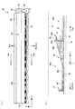
図6は、本実施の形態における光源装置11の縦方向Vの断面図を示している。なお、以下の説明においては、第1発光モジュール40a〜第5発光モジュール40eに設けられる反射板44を、それぞれ、第1反射板441〜第5反射板445と呼ぶことにする。ここで、図6においては、第1反射板441〜第5反射板445のそれぞれに設けられる調整部材45の記載を省略している。 FIG. 6 shows a cross-sectional view in the vertical direction V of the
第1発光モジュール40aに設けられる第1反射板441は、一端側から他端側に向かう長さすなわちその縦方向Vの長さが第1縦方向長さLaに設定されている。また、第1反射板441における第1反射部44aの縦方向Vの長さは第1平坦部長さLa1に、第2反射部44bの縦方向Vの長さは第1傾斜部長さLa2に、それぞれ設定されている。さらに、第1反射板441における第2反射部44bの拡散板12に向かう方向の高さは第1高さHaに設定されている。そして、第1反射板441において第1反射部44aと第2反射部44bとのなす傾斜角度θは、第1傾斜角度θaに設定されている。 The length of the
第2発光モジュール40bに設けられる第2反射板442は、一端側から他端側に向かう長さすなわちその縦方向Vの長さが第2縦方向長さLbに設定されている。また、第2反射板442における第1反射部44aの縦方向Vの長さは第2平坦部長さLb1に、第2反射部44bの縦方向Vの長さは第2傾斜部長さLb2に、それぞれ設定されている。さらに、第2反射板442における第2反射部44bの拡散板12に向かう方向の高さは第2高さHbに設定されている。そして、第2反射板442において第1反射部44aと第2反射部44bとのなす傾斜角度θは、第2傾斜角度θbに設定されている。 The length of the
第3発光モジュール40cに設けられる第3反射板443は、一端側から他端側に向かう長さすなわちその縦方向Vの長さが第3縦方向長さLcに設定されている。また、第3反射板443における第1反射部44aの縦方向Vの長さは第3平坦部長さLc1に、第2反射部44bの縦方向Vの長さは第3傾斜部長さLc2に、それぞれ設定されている。さらに、第3反射板443における第2反射部44bの拡散板12に向かう方向の高さは第3高さHcに設定されている。そして、第3反射板443において第1反射部44aと第2反射部44bとのなす傾斜角度θは、第3傾斜角度θcに設定されている。 The
第4発光モジュール40dに設けられる第4反射板444は、一端側から他端側に向かう長さすなわちその縦方向Vの長さが第4縦方向長さLdに設定されている。また、第4反射板444における第1反射部44aの縦方向Vの長さは第4平坦部長さLd1に、第2反射部44bの縦方向Vの長さは第4傾斜部長さLd2に、それぞれ設定されている。さらに、第4反射板444における第2反射部44bの拡散板12に向かう方向の高さは第4高さHdに設定されている。そして、第4反射板444において第1反射部44aと第2反射部44bとのなす傾斜角度θは、第4傾斜角度θdに設定されている。 The length of the
第5発光モジュール40eに設けられる第5反射板445は、一端側から他端側に向かう長さすなわちその縦方向Vの長さが第5縦方向長さLeに設定されている。また、第5反射板445における第1反射部44aの縦方向Vの長さは第5平坦部長さLe1に、第2反射部44bの縦方向Vの長さは第5傾斜部長さLe2に、それぞれ設定されている。さらに、第5反射板445における第2反射部44bの拡散板12に向かう方向の高さは第5高さHeに設定されている。そして、第5反射板445において第1反射部44aと第2反射部44bとのなす傾斜角度θは、第5傾斜角度θeに設定されている。 The
本実施の形態では、第1縦方向長さLa〜第5縦方向長さLeが、La=Lb=Lc=Ld=Leの関係を有している。また、第1平坦部長さLa1〜第5平坦部長さLe1がLa1=Lb1=Lc1=Ld1=Le1の関係を有し、第1傾斜部長さLa2〜第5傾斜部長さLe2がLa2=Lb2=Lc2=Ld2=Le2の関係を有している。さらに、第1発光モジュール40a〜第5発光モジュール40eのそれぞれにおける平坦部長さと傾斜部長さとの比の関係は、La2/La1=Lb2/Lb1=Lc2/Lc1=Ld2/Ld1=Le2/Le1となっている。そして、本実施の形態では、第1高さHa〜第5高さHeがHa<Hb<Hc<Hd<Heの関係を有しており、第1傾斜角度θa〜第5傾斜角度θeがθa<θb<θc<θd<θeの関係を有するようになっている。 In the present embodiment, the first vertical length La to the fifth vertical length Le have a relationship of La = Lb = Lc = Ld = Le. Further, the first flat portion length La1 to the fifth flat portion length Le1 have a relationship of La1 = Lb1 = Lc1 = Ld1 = Le1, and the first inclined portion length La2 to the fifth inclined portion length Le2 are La2 = Lb2 = Lc2. = Ld2 = Le2. Furthermore, the relationship between the ratio of the flat portion length and the inclined portion length in each of the first
本実施の形態では、例えば第1発光モジュール40aを第1の発光モジュールとしてみた場合に、第2発光モジュール40bが第2の発光モジュールとなる。また、例えば第2発光モジュール40bを第1の発光モジュールとしてみた場合に、第3発光モジュール40cが第2の発光モジュールとなる。さらに、例えば第3発光モジュール40cを第1の発光モジュールとしてみた場合に、第4発光モジュール40dが第2の発光モジュールとなる。さらにまた、例えば第4発光モジュール40dを第1の発光モジュールとしてみた場合に、第5発光モジュール40eが第2の発光モジュールとなる。 In the present embodiment, for example, when the first
では次に、図1〜図6を参照して、本実施の形態に係るバックライト装置10の発光動作について説明する。
図示しない電源により、給電ケーブル33を介して発光装置32を構成する第1発光モジュール40a〜第5発光モジュール40eに電力供給が行われる。すると、例えば第1発光モジュール40aでは、配線基板42を介して、発光部41を構成する各発光ユニット50に設けられた赤色LED52R、第1緑色LED52Ga、青色LED52B、第2緑色LED52Gbにそれぞれ電流が流れる。その結果、各発光ユニット50の赤色LED52R、第1緑色LED52Ga、青色LED52B、第2緑色LED52Gbから、赤色(R)、緑色(G)、青(B)の光がTop側に向かって出射される。Next, the light emission operation of the
Power is supplied from the power source (not shown) to the first
そして、各発光ユニット50からTop側に向けて出射されたRGBの光は、バックライトフレーム31内を進むうちに混色され、白色光となる。そして、混色された白色光は反射板44によって反射され、拡散板12側へと向かう。なお、他の第2発光モジュール40b〜第5発光モジュール40eにおいても、同様の手順によって出射、混色された白色光が拡散板12側へと向かう。そして、拡散板12に入射した白色光は、拡散板12でさらに混色および輝度の均一化がなされた後、プリズムシート13、14および輝度向上フィルム15を透過し、液晶表示モジュール20に向けて出射される。 The RGB light emitted from each
本実施の形態のバックライト装置10では、第1発光モジュール40a〜第5発光モジュール40eのそれぞれに設けられた発光部41が、液晶表示モジュール20の液晶パネル21のパネル面とほぼ平行な方向に光を出射し、第1発光モジュール40a〜第5発光モジュール40eのそれぞれに設けられた反射板44が、各々の発光部41から出射された光を液晶パネル21に向けて反射している。これにより、第1発光モジュール40a〜第5発光モジュール40eでは、発光部41から出射されたRGB各色の光が混色するのに十分な光路長さが確保される。したがって、例えば発光部41と拡散板12との距離を短くしても十分な混色が行われ得ることとなるため、バックライト装置10の薄型化を図ることが可能になる。 In the
図7は、第2発光モジュール40bにおける光の挙動を説明するための図である。
なお、説明の便宜上、第2発光モジュール40bの発光部41から出射される光のうち、第2発光モジュール40bの第1反射部44aへと向かう光を第1の出射光Bm1、第2発光モジュール40bの第2反射部44bへと向かう光を第2の出射光Bm2、第2発光モジュール40bのBottom側に隣接して配置される第1発光モジュール40aの調整部材45へと向かう光を第3の出射光Bm3、第2発光モジュール40bの吸収部46へと向かう光を第4の出射光Bm4と呼ぶ。
ここでは、第2発光モジュール40bにおける光の挙動について説明を行うが、他の第1発光モジュール40a、第3発光モジュール40c〜第5発光モジュール40eにおいても同様である。FIG. 7 is a diagram for explaining the behavior of light in the second
For convenience of explanation, of the light emitted from the
Here, the behavior of light in the second
まず、第1の出射光Bm1および第2の出射光Bm2の挙動について説明する。
図7に示すように、発光部41から出射された第1の出射光Bm1は、第1反射部44aで反射する。このとき、第1の出射光Bm1の一部は第1反射部44aにて拡散反射して拡散板12へと向かう。また、第1の出射光Bm1の一部は第1反射部44aで正反射してTop側に向けて進行しつつ拡散板12に向かう。
また、発光部41から出射された第2の出射光Bm2は、第2反射部44bで反射する。このとき、第2の出射光Bm2の一部は第2反射部44bにて拡散反射して拡散板12へと向かう。また、第2の出射光Bm2の一部は第2反射部44bで正反射してTop側に進行しつつ拡散板12に向かう。First, the behavior of the first outgoing light Bm1 and the second outgoing light Bm2 will be described.
As shown in FIG. 7, the first outgoing light Bm1 emitted from the
Further, the second emitted light Bm2 emitted from the
ここで、LED52から出射される光は拡散光であり、拡散光の性質上、第2発光モジュール40bにおいて、発光部41(各発光ユニット50)に近い側すなわちBottom側の領域に比べ、発光部41から遠い側すなわちTop側では光の強度が低くなる。本実施の形態では、この拡散光の性質を考慮して、反射板44のうち、発光部41に近い側には発光部41の光軸方向に対し反射面がほぼ平行な第1反射部44aを位置させ、拡散板12に向かう反射光の光量の割合を小さくするようにしている。一方、発光部41から遠い側には発光部41の光軸方向に対して傾斜する第2反射部44bを位置させ、拡散板12に向かう反射光の光量の割合を大きくするようにしている。
このような構成を採用することで、第2発光モジュール40bを含む第1発光モジュール40a〜第5発光モジュール40eのそれぞれにおいて、反射板44による光の反射量の均一化を図っている。Here, the light emitted from the
By adopting such a configuration, the amount of light reflected by the
次に、第3の出射光Bm3の挙動について説明する。
図7に示すように、発光部41から出射された第3の出射光Bm3は、Bottom側に隣接する第1発光モジュール40aの調整部材45において、一部が吸収されあるいは反射される。そして、第3の出射光Bm3のうち、調整部材45で反射されず且つ調整部材45に吸収されない光は、調整部材45を透過して拡散板12に向かう。ここで、調整部材45では、発光部41に近い一端側45aでは厚みを厚くして、光の強度が高い発光部41の近傍では第3の出射光Bm3を透過させ難くしている。一方、調整部材45では、発光部41から遠い他端側45bでは厚みを一端側45aよりも薄くして、発光部41から遠ざかることにより光の強度が低下した分を補うように、光を透過させ易くしている。Next, the behavior of the third emitted light Bm3 will be described.
As shown in FIG. 7, a part of the third emitted light Bm3 emitted from the
これにより、第2発光モジュール40bを含む第1発光モジュール40a〜第5発光モジュール40eのそれぞれでは、調整部材45を設けることにより、発光部41が設けられた領域の直上部付近の光量が他の領域と比べて著しく多くなるのを抑制している。また、調整部材45は、発光部41から出射される第3の出射光Bm3を全て吸収あるいは反射して遮ることがないように構成されている。このため、第2発光モジュール40bを含む第1発光モジュール40a〜第5発光モジュール40eのそれぞれでは、調整部材45を設けることによって、調整部材45が配置される領域の直上部付近の光量が、他の領域と比べて著しく少なくなるという事態が回避される。 Thereby, in each of the first
今度は、第4の出射光Bm4の挙動について説明する。
図7に示すように、発光部41から出射された第4の出射光Bm4は、吸収部46においてその一部が吸収される。また、第4の出射光Bm4の一部は、吸収部46で反射して拡散板12に向かう。
上述したように、拡散光の性質上、発光部41近傍の光量は、他の領域と比較して多くなる。さらに、発光部41から出射される光のうち、第1反射部44aにおいて発光部41に近い側に入射する光ほどその入射角が小さくなることから、第1反射部44aで正反射した光の反射角も小さくなる。したがって、第1反射部44aにおいて発光部41に近い側で正反射した光は、例えば拡散板12における発光部41の直上部付近に集中しやすくなる。そのため、発光部41の直上部付近の光量は、他の領域と比較して多くなりやすい。Next, the behavior of the fourth outgoing light Bm4 will be described.
As shown in FIG. 7, a part of the fourth emitted light Bm4 emitted from the
As described above, due to the nature of the diffused light, the amount of light in the vicinity of the
これに対し、第2発光モジュール40bを含む第1発光モジュール40a〜第5発光モジュール40eのそれぞれでは、吸収部46を発光部41の出射方向すなわちTop側且つ発光部41の近傍に設けることにより、発光部41から出射された光の光量を調整した上で、拡散板12側へと反射させている。これにより、発光部41付近の直上部の光量が、他の領域と比較して著しく多くなるのを抑制している。さらに、吸収部46は、上述したように発光部41から入射してくる第4の出射光Bm4を全て吸収せず、一部を反射させるように構成されている。したがって、第2発光モジュール40bを含む第1発光モジュール40a〜第5発光モジュール40eのそれぞれでは、吸収部46が設けられる領域の直上部の光量が、他の領域と比較して著しく少なくなるのを抑制している。 On the other hand, in each of the first
このように、本実施の形態では、第1発光モジュール40a〜第5発光モジュール40eの構成に工夫を施すことで、第1発光モジュール40a〜第5発光モジュール40eの直上となる領域における輝度ムラの抑制を図っている。 As described above, in the present embodiment, by devising the configuration of the first
図8は、本実施の形態の第1発光モジュール40a〜第5発光モジュール40eのそれぞれから出射される光と、拡散板12での光の到達領域との関係を説明するための図である。
なお、以下の説明においては、拡散板12のうち、第1発光モジュール40aの直上となる領域を第1の領域A1、第2発光モジュール40bの直上となる領域を第2の領域A2、第3発光モジュール40cの直上となる領域を第3の領域A3、第4発光モジュール40dの直上となる領域を第4の領域A4、そして第5発光モジュール40eの直上となる領域を第5の領域A5と呼ぶ。本実施の形態では、第1発光モジュール40a〜第5発光モジュール40eに設けられる第1反射板441〜第5反射板445の第1縦方向長さLa〜第5縦方向長さLeが同じ大きさに設定されているため、これら第1の領域A1〜第5の領域A5も、それぞれの面積が等しくなっている。FIG. 8 is a diagram for explaining the relationship between the light emitted from each of the first
In the following description, in the diffusing
また、以下の説明においては、第1発光モジュール40aから出力される光を第1の光L1、第2発光モジュール40bから出力される光を第2の光L2、第3発光モジュール40cから出力される光を第3の光L3、第4発光モジュール40dから出力される光を第4の光L4、第5発光モジュール40eから出力される光を第5の光L5と呼ぶ。 In the following description, the light output from the first
本実施の形態のように、第1発光モジュール40a〜第5発光モジュール40eのそれぞれに搭載される発光ユニット50の数が同数である場合、第1発光モジュール40a〜第5発光モジュール40eのそれぞれに供給される電流の大きさが同じであるものと仮定すると、第1発光モジュール40a〜第5発光モジュール40eのそれぞれから出射される第1の光L1〜第5の光L5の光量はほぼ同じになる。 When the number of the
例えば第1発光モジュール40aから出射された第1の光L1は、主としてその直上に位置する第1の領域A1に向かう第1の主光LM1となるが、その一部は第1の領域A1ではなく、これよりもTop側すなわち出射方向下流側となる第2の領域A2〜第5の領域A5に向かう第1の副光LS1となる。また、例えば第2発光モジュール40bから出射された第2の光L2は、主としてその直上に位置する第2の領域A2に向かう第2の主光LM2となるが、その一部はこれよりもTop側となる第3の領域A3〜第5の領域A5に向かう第2の副光LS2となる。さらに、例えば第3発光モジュール40cから出射された第3の光L3は、主としてその直上に位置する第3の領域A3に向かう第3の光LM3となるが、その一部はこれよりもTop側となる第4の領域A4および第5の領域A5に向かう第3の副光LS3となる。さらにまた、例えば第4発光モジュール40dから出射された第4の光L4は、主としてその直上に位置する第4の領域A4に向かう第4の主光LM4となるが、その一部はこれよりもTop側となる第5の領域A5に向かう第4の副光LS4となる。そして、例えば第5発光モジュール40eから出射された光は、主としてその直上に位置する第5の領域A5に向かう第5の主光LM5となるが、その一部はこれよりもTop側となるバックライトフレーム31のTop側の側面部内側に向かう第5の副光LS5となる。 For example, the first light L1 emitted from the first
また、第1発光モジュール40a〜第5発光モジュール40eのそれぞれから拡散板12に向かう光の全てが拡散板12に入射するわけではなく、その一部は拡散板12において発光装置32側に反射される。このとき、第1発光モジュール40a〜第5発光モジュール40eのそれぞれに設けられた発光部41では、Bottom側からTop側に向かって光を出射しているため、拡散板12からの反射光の多くは、Bottom側からTop側へと向かう。 Further, not all of the light directed from each of the first
このため、第1の領域A1には、基本的に第1の主光LM1が照射されるのに対し、第2の領域A2には、第2の主光LM2に加えこれよりもBottom側から入射してくる第1の副光LS1の一部も照射されることになる。また、第3の領域A3には、第3の主光LM3に加えこれよりもBottom側から入射してくる第2の副光LS2および第1の副光LS1の一部も照射されることになる。さらに、第4の領域A4には、第4の主光LM4に加えこれよりもBottom側から入射してくる第3の副光LS3、第2の副光LS2および第1の副光LS1の一部も照射されることになる。さらにまた、第5の領域A5には、第5の主光LM5に加えこれよりもBottom側から入射してくる第4の副光LS4、第3の副光LS3、第2の副光LS2および第1の副光LS1の一部も照射されることになる。 Therefore, the first region A1 is basically irradiated with the first main light LM1, whereas the second region A2 is added to the second main light LM2 from the bottom side in addition to the second main light LM2. A part of the incident first sub-light LS1 is also irradiated. In addition to the third main light LM3, the third region A3 is also irradiated with a part of the second sub-light LS2 and the first sub-light LS1 incident from the bottom side. Become. Further, in the fourth area A4, in addition to the fourth main light LM4, one of the third sub light LS3, the second sub light LS2, and the first sub light LS1 incident from the bottom side. The part will also be irradiated. Furthermore, in the fifth region A5, in addition to the fifth main light LM5, the fourth sub-light LS4, the third sub-light LS3, the second sub-light LS2, and the second sub-light LS2 that enter from the bottom side. A part of the first auxiliary light LS1 is also irradiated.
したがって、第1の光L1〜第5の光L5の光量が同じ大きさに設定されているものと仮定すると、第1の領域A1に照射される光の光量よりも第2の領域A2に照射される光の光量が多くなりやすく、第2の領域A2に照射される光の光量よりも第3の領域A3に照射される光の光量が多くなりやすい。また、第3の領域A3に照射される光の光量よりも第4の領域A4に照射される光の光量が多くなりやすく、第4の領域A4に照射される光の光量よりも第5の領域A5に照射される光の光量が多くなりやすい。 Therefore, assuming that the light amounts of the first light L1 to the fifth light L5 are set to the same magnitude, the second region A2 is irradiated more than the light amount irradiated to the first region A1. The amount of light emitted tends to increase, and the amount of light irradiated onto the third region A3 tends to increase more than the amount of light irradiated onto the second region A2. In addition, the amount of light irradiated to the fourth region A4 is likely to be larger than the amount of light irradiated to the third region A3, and the fifth amount of light is irradiated to the fourth region A4. The amount of light applied to the area A5 tends to increase.
このため、第1発光モジュール40a〜第5発光モジュール40eを用いてバックライト装置10を構成した場合に、Bottom側よりもTop側において光が累積していくことになり、結果としてBottom側よりもTop側の光量が大きくなりやすくなる。すると、Top側に比べてBottom側の輝度が低下し、縦方向Vに輝度ムラが生ずるおそれがある。 For this reason, when the
これに対し、本実施の形態では、図6を用いて説明したように、発光装置32において最もBottom側となる第1発光モジュール40aにおける第1反射板441を第1傾斜角度θaおよび第1高さHaに設定する一方、第1発光モジュール40aのTop側に隣接する第2発光モジュール40bにおける第2反射板442を第1傾斜角度θaよりも大きい第2傾斜角度θbおよび第1高さHaよりも大きい第2高さHbとした。また、第2発光モジュール40bのTop側に隣接する第3発光モジュール40cにおける第3反射板443を第2傾斜角度θbよりも大きい第3傾斜角度θcおよび第2高さHbよりも大きい第3高さHcとした。さらに、第3発光モジュール40cのTop側に隣接する第4発光モジュール40dにおける第4反射板444を第3傾斜角度θcよりも大きい第4傾斜角度θdおよび第3高さHcよりも大きい第4高さHdとした。さらにまた、第4発光モジュール40dのTop側に隣接し最もTop側となる第5発光モジュール40eにおける第5反射板445を第4傾斜角度θdよりも大きい第5傾斜角度θeおよび第4高さHdよりも大きい第5高さHeとした。 On the other hand, in the present embodiment, as described with reference to FIG. 6, the
このような構成を採用することで、例えば第1発光モジュール40aから出射された第1の副光LS1は、第2発光モジュール40bに設けられた第2反射板442(特に第2反射部44b)で反射されやすくなる。その結果、よりTop側の第3発光モジュール40c〜第5発光モジュール40e側に向かう第1の副光LS1の光量は、この構成を採用しない場合と比較してより少なくなる。また、第1の副光LS1のうち、第2発光モジュール40bを通過した一部の光についても、第3発光モジュール40cに設けられた第3反射板443(特に第2反射部44b)で反射されやすくなる。このため、よりTop側の第4発光モジュール40dおよび第5発光モジュール40e側に向かう第1の副光LS1の量は、この構成を採用しない場合と比較してより少なくなる。さらに、第1の副光LS1のうち、第3発光モジュール40cを通過した一部の光についても、第4発光モジュール40dに設けられた第4反射板444(特に第2反射部44b)で反射されやすくなる。これにより、よりTop側の第5発光モジュール40eに向かう第1の副光LS1の量は、この構成を採用しない場合と比較してより小さくなる。なお、ここでは詳述しないが、他の第2発光モジュール40b〜第4発光モジュール40dから出射された第2の副光LS2〜第4の副光LS4についても、第1の副光LS1と同様、よりTop側に設けられた発光モジュール40の反射板44で反射される確率が高まり、結果として、さらにTop側に設けられた他の発光モジュール40に向かう光の光量を少なくすることができる。 By adopting such a configuration, for example, the first auxiliary light LS1 emitted from the first
このように、本実施の形態では、第1発光モジュール40a〜第5発光モジュール40eに設けられる第1反射板441〜第5反射板445の形状に工夫を施すことで、Bottom側の発光モジュール40から出射された副光が、そのTop側に配置された他の発光モジュール40を介してさらにそのTop側に配置されたさらに他の発光モジュール40側に向かいにくくなるようにしたので、Bottom側よりもTop側において光が累積していくことに起因する輝度ムラを抑制することができる。 As described above, in the present embodiment, the shape of the first reflecting
ここで、図8に示す例において、第1発光モジュール40a〜第5発光モジュール40eから出射され、バックライトフレーム31のTop側の側面部内側に到達した光は、この部位に設けられた吸収体35によって吸収される。したがって、この部位における光量が増加し、この直上となる領域において輝線が発生するという事態を回避することができる。 Here, in the example shown in FIG. 8, the light emitted from the first
<実施の形態2>
本実施の形態は、実施の形態1とほぼ同様であるが、第1発光モジュール40a〜第5発光モジュール40eにおける第1反射板441〜第5反射板445の構成の一部を異ならせるようにしたものである。なお、本実施の形態において、実施の形態1と同様のものについては、同じ符号を付してその詳細な説明を省略する。<Embodiment 2>
Although the present embodiment is substantially the same as the first embodiment, a part of the configuration of the first reflecting
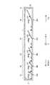
図9は、本実施の形態における光源装置11の縦方向Vの断面図を示している。ここで、図9においては、図6と同様、第1反射板441〜第5反射板445のそれぞれに設けられる調整部材45の記載を省略している。 FIG. 9 shows a cross-sectional view in the vertical direction V of the
本実施の形態では、第1縦方向長さLa〜第5縦方向長さLeが、La<Lb<Lc<Ld<Leの関係を有している。また、第1平坦部長さLa1〜第5平坦部長さLe1がLa1<Lb1<Lc1<Ld1<Le1の関係を有し、第1傾斜部長さLa2〜第5傾斜部長さLe2がLa2<Lb2<Lc2<Ld2<Le2の関係を有している。さらに、第1発光モジュール40a〜第5発光モジュール40eのそれぞれにおける平坦部長さと傾斜部長さとの比の関係は、La2/La1=Lb2/Lb1=Lc2/Lc1=Ld2/Ld1=Le2/Le1となっている。そして、本実施の形態では、第1高さHa〜第5高さHeがHa<Hb<Hc<Hd<Heの関係を有しているが、第1傾斜角度θa〜第5傾斜角度θeがθa=θb=θc=θd=θeの関係を有するようになっている。 In the present embodiment, the first vertical length La to the fifth vertical length Le have a relationship of La <Lb <Lc <Ld <Le. Further, the first flat portion length La1 to the fifth flat portion length Le1 have a relationship of La1 <Lb1 <Lc1 <Ld1 <Le1, and the first inclined portion length La2 to the fifth inclined portion length Le2 are La2 <Lb2 <Lc2. <Ld2 <Le2 is satisfied. Furthermore, the relationship between the ratio of the flat portion length and the inclined portion length in each of the first
図10は、本実施の形態の第1発光モジュール40a〜第5発光モジュール40eのそれぞれから出射される光と、拡散板12での光の到達領域との関係を説明するための図である。本実施の形態では、第1発光モジュール40a〜第5発光モジュール40eに設けられる第1反射板441〜第5反射板445の第1縦方向長さLa〜第5縦方向長さLeが、La<Lb<Lc<Ld<Leとなるように設定されているため、これら第1の領域A1〜第5の領域A5の面積も、A1<A2<A3<A4<A5の関係を有するようになっている。 FIG. 10 is a diagram for explaining the relationship between the light emitted from each of the first
第1の領域A1には、基本的に第1の主光LM1が照射されるのに対し、第2の領域A2には、第2の主光LM2に加えこれよりもBottom側から入射してくる第1の副光LS1の一部も照射されることになる。また、第3の領域A3には、第3の主光LM3に加えこれよりもBottom側から入射してくる第2の副光LS2および第1の副光LS1の一部も照射されることになる。さらに、第4の領域A4には、第4の主光LM4に加えこれよりもBottom側から入射してくる第3の副光LS3、第2の副光LS2および第1の副光LS1の一部も照射されることになる。さらにまた、第5の領域A5には、第5の主光LM5に加えこれよりもBottom側から入射してくる第4の副光LS4、第3の副光LS3、第2の副光LS2および第1の副光LS1の一部も照射されることになる。 The first region A1 is basically irradiated with the first main light LM1, whereas the second region A2 is incident from the bottom side in addition to the second main light LM2. A part of the coming first auxiliary light LS1 is also irradiated. In addition to the third main light LM3, the third region A3 is also irradiated with a part of the second sub-light LS2 and the first sub-light LS1 incident from the bottom side. Become. Further, in the fourth area A4, in addition to the fourth main light LM4, one of the third sub light LS3, the second sub light LS2, and the first sub light LS1 incident from the bottom side. The part will also be irradiated. Furthermore, in the fifth region A5, in addition to the fifth main light LM5, the fourth sub-light LS4, the third sub-light LS3, the second sub-light LS2, and the second sub-light LS2 that enter from the bottom side. A part of the first auxiliary light LS1 is also irradiated.
したがって、第1の光L1〜第5の光L5の光量が同じ大きさに設定されているものと仮定すると、第1の領域A1に照射される光の光量よりも第2の領域A2に照射される光の光量が多くなり、第2の領域A2に照射される光の光量よりも第3の領域A3に照射される光の光量が多くなる。また、第3の領域A3に照射される光の光量よりも第4の領域A4に照射される光の光量が多くなり、第4の領域A4に照射される光の光量よりも第5の領域A5に照射される光の光量が多くなる。 Therefore, assuming that the light amounts of the first light L1 to the fifth light L5 are set to the same magnitude, the second region A2 is irradiated more than the light amount irradiated to the first region A1. The amount of light emitted increases, and the amount of light applied to the third region A3 is greater than the amount of light applied to the second region A2. Further, the amount of light irradiated to the fourth region A4 is larger than the amount of light irradiated to the third region A3, and the fifth region is larger than the amount of light irradiated to the fourth region A4. The amount of light irradiated to A5 increases.
これに対し、本実施の形態では、上述した構成を備えることにより、実施の形態1と同様に、第1発光モジュール40a〜第4発光モジュール40dから出射された第1の副光LS1〜第4の副光LS4が、よりTop側に設けられた発光モジュール40の反射板44で反射される確率が高まり、結果として、さらにTop側に設けられた他の発光モジュール40に向かう光の光量を少なくすることができる。 In contrast, in the present embodiment, by providing the above-described configuration, the first sub-lights LS1 to LS1 to LS4 emitted from the first light-emitting
また、本実施の形態では、上述したように第1の領域A1〜第5の領域A5の面積がA1<A2<A3<A4<A5となる関係を有しているので、Bottom側の発光モジュール40からそのTop側に設けられる他の発光モジュール40に光が向かったとしても、これら第1の領域A1〜第5の領域A5のそれぞれに照射される光の密度をほぼ等しくすることができる。 In the present embodiment, since the area of the first region A1 to the fifth region A5 has a relationship of A1 <A2 <A3 <A4 <A5 as described above, the bottom side light emitting module Even if the light is directed from the
このように、本実施の形態においては、Bottom側よりもTop側において光が累積していくことに起因する輝度ムラを、実施の形態1と比較してさらに抑制することができる。 As described above, in the present embodiment, the luminance unevenness caused by the accumulation of light on the Top side rather than the Bottom side can be further suppressed as compared with the first embodiment.
<実施の形態3>
本実施の形態は、実施の形態2とほぼ同様であるが、第1発光モジュール40a〜第5発光モジュール40eにおける第1反射板441〜第5反射板445の構成の一部をさらに異ならせるようにしたものである。なお、本実施の形態において、実施の形態1と同様のものについては、同じ符号を付してその詳細な説明を省略する。<Embodiment 3>
The present embodiment is substantially the same as the second embodiment, but a part of the configuration of the first reflecting
図11は、本実施の形態における光源装置11の縦方向Vの断面図を示している。ここで、図11では、図9と同様、第1反射板441〜第5反射板445のそれぞれに設けられる調整部材45の記載を省略している。 FIG. 11 shows a cross-sectional view in the vertical direction V of the
本実施の形態では、第1縦方向長さLa〜第5縦方向長さLeが、La<Lb<Lc<Ld<Leの関係を有している。また、第1平坦部長さLa1〜第5平坦部長さLe1がLa1<Lb1<Lc1<Ld1<Le1の関係を有し、第1傾斜部長さLa2〜第5傾斜部長さLe2がLa2<Lb2<Lc2<Ld2<Le2の関係を有している。さらに、第1発光モジュール40a〜第5発光モジュール40eのそれぞれにおける平坦部長さと傾斜部長さとの比の関係は、La2/La1=Lb2/Lb1=Lc2/Lc1=Ld2/Ld1=Le2/Le1となっている。そして、本実施の形態では、第1高さHa〜第5高さHeがHa<Hb<Hc<Hd<Heの関係を有しており、さらに、第1傾斜角度θa〜第5傾斜角度θeがθa<θb<θc<θd<θeの関係を有するようになっている。 In the present embodiment, the first vertical length La to the fifth vertical length Le have a relationship of La <Lb <Lc <Ld <Le. Further, the first flat portion length La1 to the fifth flat portion length Le1 have a relationship of La1 <Lb1 <Lc1 <Ld1 <Le1, and the first inclined portion length La2 to the fifth inclined portion length Le2 are La2 <Lb2 <Lc2. <Ld2 <Le2 is satisfied. Furthermore, the relationship between the ratio of the flat portion length and the inclined portion length in each of the first
本実施の形態では、上述した構成を採用することにより、実施の形態2で説明した構成と比較して、第1発光モジュール40a〜第4発光モジュール40dから出射される第1の副光LS1〜第4の副光LS4の光の光量を、さらに少なくすることができる。より具体的に説明すると、第1の光L1〜第4の光L4に占める第1の副光LS1〜第4の副光LS4の比率をより小さくすること、換言すれば、第1の光L1〜第4の光L4に占める第1の主光LM1〜第4の主光LM4の比率をより大きくすることができる。その結果、第1の領域A1〜第5の領域A5に照射される光の光量の差をより少なくすることができる。 In the present embodiment, by adopting the above-described configuration, the first sub-lights LS1 to LS1 emitted from the first
また、本実施の形態では、実施の形態2と同様、第1の領域A1〜第5の領域A5の面積がA1<A2<A3<A4<A5となる関係を有しているので、Bottom側の発光モジュール40からそのTop側に設けられる他の発光モジュール40に光が向かったとしても、これら第1の領域A1〜第5の領域A5のそれぞれに照射される光の密度をほぼ等しくすることができる。 In the present embodiment, as in the second embodiment, the area of the first region A1 to the fifth region A5 has a relationship of A1 <A2 <A3 <A4 <A5. Even if light is directed from the
このように、本実施の形態においては、Bottom側よりもTop側において光が累積していくことに起因する輝度ムラを、実施の形態2と比較してさらに抑制することができる。 Thus, in the present embodiment, luminance unevenness caused by the accumulation of light on the Top side rather than the Bottom side can be further suppressed as compared with the second embodiment.
なお、実施の形態1〜3では、所謂チップオンボード(COB)型の発光ユニット50を用いる場合を例に説明を行ったが、発光ユニット50の構成はこれに限られない。
図12(a)は、発光ユニット50の上面図を、図12(b)は図12(a)のXIIb−XIIb断面図を、それぞれ示している。
図12(a)、(b)に示すように、この例における発光ユニット50は、4個のLED52(赤色LED52R、第1緑色LED52Ga、青色LED52Bおよび第2緑色LED52Gb)と、凹部530を有しこれら4個のLED52を凹部530の内側に収容する樹脂ケース510とを備えている。また、図12(b)に示すように、発光ユニット50は、樹脂ケース510の凹部530を埋めるように設けられ、LED52から出射される光に対して透明な封止樹脂540をさらに備えている。封止樹脂540を設けることにより、凹部530の内側に配置される4個のLED52を例えば湿気などから保護している。In the first to third embodiments, the case where a so-called chip-on-board (COB) type
12A shows a top view of the
As shown in FIGS. 12A and 12B, the
また、発光ユニット50は、樹脂ケース510に保持されるリードフレーム520をさらに有している。そして、各LED52は、それぞれに対応するリードフレーム520と電気的および機械的に接続されている。また、リードフレーム520の一端は、樹脂ケース510の外部に突出している。この発光ユニット50を図3に示す配線基板42に取り付ける際には、このリードフレーム520と、配線基板42の配線とが電気的および機械的に接続される。
そして、配線基板42からリードフレーム520を介して各LED52に電流を流すことにより、各LED52が発光する。The
Each
なお、上述した各実施の形態では、赤色LED52R、第1緑色LED52Ga、青色LED52Bおよび第2緑色LED52Gbから出射されるRGBの光を混色させて白色光を生成するようにしていたが、これに限られない。例えばLED52として青色光を出射するものを用い、レンズ54内にLED52から出射される青色光を緑色光および赤色光に変換する蛍光体を含有させておくことで、白色光を生成するように構成してもよい。また、例えばLED52として紫外光を出射するものを用い、レンズ54内にLED52から出射される紫外光を青色光、緑色光および赤色光に変換する蛍光体を含有させておくことで、白色光を生成するように構成してもよい。 In each of the embodiments described above, white light is generated by mixing the RGB light emitted from the
10…バックライト装置、11…光源装置、12…拡散板、13、14…プリズムシート、15…輝度向上フィルム、20…液晶表示モジュール、21…液晶パネル、22、23…偏光板、31…バックライトフレーム、32…発光装置、33…給電ケーブル、35…吸収体、40…発光モジュール、40a…第1発光モジュール、40b…第2発光モジュール、40c…第3発光モジュール、40d…第4発光モジュール、40e…第5発光モジュール、41…発光部、42…配線基板、43…コネクタ、44…反射板、441…第1反射板、442…第2反射板、443…第3反射板、444…第4反射板、445…第5反射板、44a…第1反射部、44b…第2反射部、50…発光ユニット、51…板状基板、52…LEDDESCRIPTION OF
Claims (8)
Translated fromJapanese前記バックライト装置は、
一端側から他端側へと延びて展開されるフレームと、
前記フレームに配置され、前記一端側から前記他端側へと向かう方向と交差する方向に配列される複数の発光素子を用いて当該一端側から当該他端側に向かう光を出射する第1の発光部と、当該第1の発光部から出射された光を前記表示パネル側に向けて反射する第1の反射部材とを有する第1の発光モジュールと、
前記フレームに前記第1の発光モジュールの前記他端側と隣り合うように配置され、前記一端側から当該他端側へと向かう方向と交差する方向に配列される複数の発光素子を用いて当該一端側から当該他端側に向かう光を出射する第2の発光部と、当該第2の発光部から出射された光を前記表示パネル側に向けて反射する第2の反射部材とを有する第2の発光モジュールと
を備え、
前記第2の反射部材の前記他端側における当該第2の反射部材の前記表示パネルに向かう方向の高さが、前記第1の反射部材の当該他端側における当該第1の反射部材の前記表示パネルに向かう方向の高さよりも大きく設定されることを特徴とする表示装置。A display device that includes a display panel that performs image display and a backlight device that is provided on the back surface of the display panel and emits light toward the display panel.
The backlight device includes:
A frame that extends from one end side to the other end side and is deployed;
A first light emitting from the one end side to the other end side using a plurality of light emitting elements arranged in the frame and arranged in a direction intersecting with the direction from the one end side to the other end side A first light emitting module comprising: a light emitting unit; and a first reflecting member that reflects light emitted from the first light emitting unit toward the display panel;
Using the plurality of light emitting elements arranged in the frame so as to be adjacent to the other end side of the first light emitting module and arranged in a direction intersecting with the direction from the one end side toward the other end side A second light emitting unit that emits light from one end side toward the other end side, and a second reflecting member that reflects the light emitted from the second light emitting unit toward the display panel. 2 light emitting modules,
The height of the second reflective member in the direction toward the display panel on the other end side of the second reflective member is the height of the first reflective member on the other end side of the first reflective member. A display device characterized by being set to be larger than a height in a direction toward the display panel.
前記第2の反射部材は、前記第2の発光部側にて前記フレームに沿って展開され、当該第2の発光部から出射される光を反射する他の第1の反射部と、当該他の第1の反射部の前記他端側から当該第2の発光部より遠ざかるにしたがって前記表示パネルに近づく方向に傾斜して展開され、当該第2の発光部から出射される光を反射する他の第2の反射部とを備え、
前記第2の反射部材において前記他の第1の反射部の面の延長線と前記他の第2の反射部とのなす傾斜角度が、前記第1の反射部材において前記第1の反射部の面の延長線と前記第2の反射部とのなす傾斜角度よりも大きく設定されることを特徴とする請求項1乃至3のいずれか1項記載の表示装置。The first reflecting member is developed along the frame on the first light emitting unit side, and includes a first reflecting unit that reflects light emitted from the first light emitting unit, and the first reflecting member. A second reflecting portion that is expanded in a direction that approaches the display panel as it moves away from the first light emitting portion from the other end side of the reflecting portion, and reflects light emitted from the first light emitting portion. And
The second reflecting member is deployed along the frame on the second light emitting unit side, and another first reflecting unit that reflects light emitted from the second light emitting unit, and the other In addition to reflecting the light emitted from the second light emitting unit, the first reflective unit is developed to be inclined toward the display panel as the distance from the other light emitting unit is farther from the second light emitting unit. And a second reflecting portion.
In the second reflecting member, an inclination angle formed between an extension line of the surface of the other first reflecting part and the other second reflecting part is determined by the first reflecting member. 4. The display device according to claim 1, wherein the display device is set to be larger than an inclination angle formed by an extended line of the surface and the second reflecting portion. 5.
前記フレームに配置され、前記一端側から前記他端側へと向かう方向と交差する方向に配列される複数の発光素子を用いて当該一端側から当該他端側に向かう光を出射する第1の発光部と、当該第1の発光部から出射された光を当該フレームとは逆側に反射する第1の反射部材とを有する第1の発光モジュールと、
前記フレームに前記第1の発光モジュールの前記他端側と隣り合うように配置され、前記一端側から前記他端側へと向かう方向と交差する方向に配列される複数の発光素子を用いて当該一端側から当該他端側へと向かう光を出射する第2の発光部と、当該第2の発光部から出射された光を当該フレームとは逆側に反射する第2の反射部材とを有する第2の発光モジュールと
を備え、
前記第2の反射部材の前記他端側における前記フレームからの高さが、前記第1の反射部材の当該他端側における当該フレームからの高さよりも大きく設定されることを特徴とする光源装置。A frame that extends from one end side to the other end side and is deployed;
A first light emitting from the one end side to the other end side using a plurality of light emitting elements arranged in the frame and arranged in a direction intersecting with the direction from the one end side to the other end side A first light emitting module having a light emitting unit and a first reflecting member that reflects light emitted from the first light emitting unit to the side opposite to the frame;
Using the plurality of light emitting elements arranged on the frame so as to be adjacent to the other end side of the first light emitting module and arranged in a direction intersecting with the direction from the one end side toward the other end side A second light emitting unit that emits light from one end side toward the other end side, and a second reflecting member that reflects the light emitted from the second light emitting unit on the side opposite to the frame. A second light emitting module,
The height from the frame on the other end side of the second reflecting member is set to be higher than the height from the frame on the other end side of the first reflecting member. .
前記第2の反射部材は、前記第2の発光部側にて前記フレームに沿って展開され、当該第2の発光部から出射される光を反射する他の第1の反射部と、当該他の第1の反射部の前記他端側から当該第2の発光部より遠ざかるにしたがって当該フレームから遠ざかる方向に傾斜して展開され、当該第2の発光部から出射される光を反射する他の第2の反射部とを備え、
前記第2の反射部材において前記他の第1の反射部の面の延長線と前記他の第2の反射部とのなす傾斜角度が、前記第1の反射部材において前記第1の反射部の面の延長線と前記第2の反射部とのなす傾斜角度よりも大きく設定されることを特徴とする請求項6または7記載の光源装置。The first reflecting member is developed along the frame on the first light emitting unit side, and includes a first reflecting unit that reflects light emitted from the first light emitting unit, and the first reflecting member. A second reflecting portion that is developed to be inclined in a direction away from the frame as it is farther from the first light emitting portion from the other end side of the reflecting portion, and reflects light emitted from the first light emitting portion; With
The second reflecting member is deployed along the frame on the second light emitting unit side, and another first reflecting unit that reflects light emitted from the second light emitting unit, and the other The other reflecting portion of the first reflecting portion is expanded in a direction inclined away from the frame as it is farther from the second light emitting portion from the other end side of the first reflecting portion, and reflects the light emitted from the second light emitting portion. A second reflecting portion,
In the second reflecting member, an inclination angle formed between an extension line of the surface of the other first reflecting part and the other second reflecting part is determined by the first reflecting member. The light source device according to claim 6, wherein the light source device is set to be larger than an inclination angle formed by an extended line of the surface and the second reflecting portion.
Priority Applications (1)
| Application Number | Priority Date | Filing Date | Title |
|---|---|---|---|
| JP2009098339AJP2010250013A (en) | 2009-04-14 | 2009-04-14 | Display device and light source device |
Applications Claiming Priority (1)
| Application Number | Priority Date | Filing Date | Title |
|---|---|---|---|
| JP2009098339AJP2010250013A (en) | 2009-04-14 | 2009-04-14 | Display device and light source device |
Publications (1)
| Publication Number | Publication Date |
|---|---|
| JP2010250013Atrue JP2010250013A (en) | 2010-11-04 |
Family
ID=43312420
Family Applications (1)
| Application Number | Title | Priority Date | Filing Date |
|---|---|---|---|
| JP2009098339ACeasedJP2010250013A (en) | 2009-04-14 | 2009-04-14 | Display device and light source device |
Country Status (1)
| Country | Link |
|---|---|
| JP (1) | JP2010250013A (en) |
Cited By (8)
| Publication number | Priority date | Publication date | Assignee | Title |
|---|---|---|---|---|
| WO2012063728A1 (en)* | 2010-11-10 | 2012-05-18 | シャープ株式会社 | Lighting device and display device |
| CN102980101A (en)* | 2012-11-28 | 2013-03-20 | 京东方科技集团股份有限公司 | Backlight module and display device utilizing same |
| WO2013128694A1 (en)* | 2012-02-29 | 2013-09-06 | 日立コンシューマエレクトロニクス株式会社 | Lighting device |
| JP2013247038A (en)* | 2012-05-28 | 2013-12-09 | Sharp Corp | Lighting apparatus and display device |
| CN103712127A (en)* | 2013-12-23 | 2014-04-09 | 京东方科技集团股份有限公司 | Light source assembly, backlight module and display device |
| CN105258027A (en)* | 2015-10-30 | 2016-01-20 | 北京京东方茶谷电子有限公司 | Backlight module and display device |
| JP2017129784A (en)* | 2016-01-21 | 2017-07-27 | 株式会社エンプラス | Light flux control member, light emitting device, plane light source device and display device |
| CN111505864A (en)* | 2020-03-30 | 2020-08-07 | 深圳市晶泰液晶显示技术有限公司 | Backlight module and display device |
Citations (3)
| Publication number | Priority date | Publication date | Assignee | Title |
|---|---|---|---|---|
| JP2001312916A (en)* | 2000-02-24 | 2001-11-09 | Sony Corp | Surface light source device |
| JP2002268040A (en)* | 2001-03-13 | 2002-09-18 | Seiko Epson Corp | Liquid crystal devices and electronic equipment |
| JP2006286639A (en)* | 2005-04-01 | 2006-10-19 | Avago Technologies General Ip (Singapore) Private Ltd | Light emitting device having a plurality of overlapping panels forming recess for emitting light |
- 2009
- 2009-04-14JPJP2009098339Apatent/JP2010250013A/ennot_activeCeased
Patent Citations (3)
| Publication number | Priority date | Publication date | Assignee | Title |
|---|---|---|---|---|
| JP2001312916A (en)* | 2000-02-24 | 2001-11-09 | Sony Corp | Surface light source device |
| JP2002268040A (en)* | 2001-03-13 | 2002-09-18 | Seiko Epson Corp | Liquid crystal devices and electronic equipment |
| JP2006286639A (en)* | 2005-04-01 | 2006-10-19 | Avago Technologies General Ip (Singapore) Private Ltd | Light emitting device having a plurality of overlapping panels forming recess for emitting light |
Cited By (10)
| Publication number | Priority date | Publication date | Assignee | Title |
|---|---|---|---|---|
| WO2012063728A1 (en)* | 2010-11-10 | 2012-05-18 | シャープ株式会社 | Lighting device and display device |
| WO2013128694A1 (en)* | 2012-02-29 | 2013-09-06 | 日立コンシューマエレクトロニクス株式会社 | Lighting device |
| JP2013211245A (en)* | 2012-02-29 | 2013-10-10 | Hitachi Consumer Electronics Co Ltd | Lighting device |
| JP2013247038A (en)* | 2012-05-28 | 2013-12-09 | Sharp Corp | Lighting apparatus and display device |
| CN102980101A (en)* | 2012-11-28 | 2013-03-20 | 京东方科技集团股份有限公司 | Backlight module and display device utilizing same |
| CN103712127A (en)* | 2013-12-23 | 2014-04-09 | 京东方科技集团股份有限公司 | Light source assembly, backlight module and display device |
| CN105258027A (en)* | 2015-10-30 | 2016-01-20 | 北京京东方茶谷电子有限公司 | Backlight module and display device |
| US10209561B2 (en) | 2015-10-30 | 2019-02-19 | Boe Technology Group Co., Ltd. | Backlight with staggered rows of LEDs |
| JP2017129784A (en)* | 2016-01-21 | 2017-07-27 | 株式会社エンプラス | Light flux control member, light emitting device, plane light source device and display device |
| CN111505864A (en)* | 2020-03-30 | 2020-08-07 | 深圳市晶泰液晶显示技术有限公司 | Backlight module and display device |
Similar Documents
| Publication | Publication Date | Title |
|---|---|---|
| JP6906968B2 (en) | Lighting device | |
| JP6776140B2 (en) | Lighting device | |
| JP2010250013A (en) | Display device and light source device | |
| KR102395088B1 (en) | Backlight unit and liquid crystal dispaly device including the same | |
| US9632355B2 (en) | Display device | |
| WO2009093583A1 (en) | Display device and light emitting device | |
| US8985799B2 (en) | Lighting device, display device and television device | |
| US9448356B2 (en) | Light-emitting diode (LED) package including multiple LEDs per housing and display device having the same as light source | |
| US20120249885A1 (en) | Lighting device, display device and television receiver | |
| US10209561B2 (en) | Backlight with staggered rows of LEDs | |
| US12038644B2 (en) | Light source apparatus and information display system using the same | |
| US9715140B2 (en) | Liquid crystal display apparatus having circuit board installed in rear chassis | |
| US9140842B2 (en) | Display device | |
| US9658487B2 (en) | Display device including support frame having reflective stepped portion | |
| EP2837963A1 (en) | Backlight unit and display device including the backlight unit | |
| US7758209B2 (en) | Illumination device and liquid crystal display device using the same | |
| CN109725455B (en) | Backlight unit and liquid crystal display device including the same | |
| JP2010108900A (en) | Display device and light-emitting device | |
| KR20200099219A (en) | Curved display device | |
| JP2010243973A (en) | Display and light source device | |
| US9703143B2 (en) | Display device | |
| JP5208039B2 (en) | Display device and light source device | |
| WO2011077864A1 (en) | Illumination device, display device, and television receiver | |
| JP5345361B2 (en) | Display device and light emitting device | |
| JP2010238635A (en) | Display device, and light source device |
Legal Events
| Date | Code | Title | Description |
|---|---|---|---|
| A621 | Written request for application examination | Free format text:JAPANESE INTERMEDIATE CODE: A621 Effective date:20120111 | |
| A977 | Report on retrieval | Free format text:JAPANESE INTERMEDIATE CODE: A971007 Effective date:20121228 | |
| A131 | Notification of reasons for refusal | Free format text:JAPANESE INTERMEDIATE CODE: A131 Effective date:20130129 | |
| A521 | Written amendment | Free format text:JAPANESE INTERMEDIATE CODE: A523 Effective date:20130328 | |
| A045 | Written measure of dismissal of application | Free format text:JAPANESE INTERMEDIATE CODE: A045 Effective date:20131029 |