JP2010246970A - Radiation tomography apparatus - Google Patents
Radiation tomography apparatusDownload PDFInfo
- Publication number
- JP2010246970A JP2010246970AJP2010153564AJP2010153564AJP2010246970AJP 2010246970 AJP2010246970 AJP 2010246970AJP 2010153564 AJP2010153564 AJP 2010153564AJP 2010153564 AJP2010153564 AJP 2010153564AJP 2010246970 AJP2010246970 AJP 2010246970A
- Authority
- JP
- Japan
- Prior art keywords
- radiation
- subject
- control value
- image generation
- current value
- Prior art date
- Legal status (The legal status is an assumption and is not a legal conclusion. Google has not performed a legal analysis and makes no representation as to the accuracy of the status listed.)
- Granted
Links
- 230000005855radiationEffects0.000titleclaimsabstractdescription50
- 238000003325tomographyMethods0.000titleclaimsabstract11
- 210000003371toeAnatomy0.000claimsabstractdescription11
- 230000008859changeEffects0.000claimsabstractdescription6
- 238000003384imaging methodMethods0.000claimsdescription18
- 230000009467reductionEffects0.000claimsdescription14
- 238000012790confirmationMethods0.000abstractdescription2
- 238000012545processingMethods0.000description35
- 231100000987absorbed doseToxicity0.000description22
- 238000002591computed tomographyMethods0.000description21
- 238000010586diagramMethods0.000description7
- 238000013480data collectionMethods0.000description6
- 238000001514detection methodMethods0.000description6
- 238000000034methodMethods0.000description5
- 230000006870functionEffects0.000description4
- 238000010521absorption reactionMethods0.000description2
- RPPBZEBXAAZZJH-UHFFFAOYSA-Ncadmium tellurideChemical compound[Te]=[Cd]RPPBZEBXAAZZJH-UHFFFAOYSA-N0.000description2
- 238000012937correctionMethods0.000description1
- 238000012986modificationMethods0.000description1
- 230000004048modificationEffects0.000description1
- 230000008569processEffects0.000description1
- 239000004065semiconductorSubstances0.000description1
Images


Landscapes
- Apparatus For Radiation Diagnosis (AREA)
Abstract
Description
Translated fromJapanese本発明は、放射線断層撮像装置に関し、特に、X線源から照射されるX線量の制御値を表示する放射線断層撮像装置に関するものである。 The present invention relates to a radiation tomographic imaging apparatus, and more particularly to a radiation tomographic imaging apparatus that displays a control value of an X-ray dose emitted from an X-ray source.
断層像を撮像する装置として、たとえば、放射線としてX線を照射し、被検体を透過したX線を検出して計算によって断層像を生成するX線CT(Computed Tomography)装置が知られている。 As an apparatus for capturing a tomographic image, for example, an X-ray CT (Computed Tomography) apparatus that emits X-rays as radiation, detects X-rays transmitted through a subject, and generates a tomographic image by calculation is known.
X線CT装置は、X線管と、被検体を介してX線管と対向するように配置された検出器アレイとからなる走査ガントリを有し、X線管から被検体に向けて照射されたX線を検出器アレイにより検出する。X線CT装置は、走査ガントリを被検体の周りに回転移動させて被検体の頭部と足先とを結ぶ体軸方向と平行に被検体を走査する。その結果、複数のビューにおいて被検体の投影データが得られる。X線CT装置は、得られた投影データを再構成して、被検体の所定のスライス厚の断層像を生成する。 The X-ray CT apparatus has a scanning gantry including an X-ray tube and a detector array arranged so as to face the X-ray tube through the subject, and is irradiated from the X-ray tube toward the subject. Detected X-rays are detected by a detector array. The X-ray CT apparatus rotates the scanning gantry around the subject and scans the subject parallel to the body axis direction connecting the head and the toes of the subject. As a result, projection data of the subject is obtained in a plurality of views. The X-ray CT apparatus reconstructs the obtained projection data and generates a tomographic image of a predetermined slice thickness of the subject.
X線管から照射されるX線量を制御する制御値、たとえば、X線管に印加する管電流値を被検体の走査位置に応じて自動制御する機能が知られている。上記のような機能を用いたX線CT装置として、X線吸収率の異なる部位に応じた管電流値を1回転ごとに算出し、テキスト表示あるいはグラフ表示する装置が知られている(たとえば、特許文献1参照)。 There is known a function of automatically controlling a control value for controlling an X-ray dose irradiated from an X-ray tube, for example, a tube current value applied to the X-ray tube in accordance with the scanning position of the subject. As an X-ray CT apparatus using the function as described above, an apparatus that calculates a tube current value corresponding to a portion having a different X-ray absorption rate for each rotation and displays a text or a graph is known (for example, Patent Document 1).
しかしながら、上記の特許文献1において、算出された管電流値は、体軸方向において走査ガントリの1回転ごとの離散値として表示される。その結果、使用者は各回転中の管電流値などを確認できないという不都合があった。
また、ヘリカルスキャンなどのように、画像と回転が一致しない場合や、マルチスライス化によって生成される画像データがいずれの走査ガントリの回転において取得されているか分かりにくい場合などにおいては、画像に対応する管電流値の確認が困難であった。However, in the above-described
Also, when the rotation does not coincide with the image, such as a helical scan, or when it is difficult to determine in which scanning gantry rotation the image data generated by multi-slicing is acquired, it corresponds to the image. It was difficult to confirm the tube current value.
本発明は、上記のような事情に鑑みてなされたものであり、その目的は、放射線量の制御値の確認および調整を容易にして操作性を向上させる放射線断層撮像装置を提供することにある。 The present invention has been made in view of the above circumstances, and an object of the present invention is to provide a radiation tomographic imaging apparatus that facilitates confirmation and adjustment of a radiation dose control value and improves operability. .
上記目的を達成するため、上記の本発明の放射線断層撮像装置は、放射線源と、被検体を介して放射線源と対向するように配置された放射線検出器とを有し、放射線源および放射線検出器の少なくとも一方を被検体の周りに回転移動させて、被検体を走査する走査手段と、放射線源から照射される放射線量を制御する制御値を算出する制御値算出手段と、走査手段の回転方向および被検体の頭部と足先とを結ぶ体軸方向において算出された制御値の少なくとも一方を被検体の位置情報に対応させて表示する表示手段とを有する。 In order to achieve the above object, the above-described radiation tomographic imaging apparatus of the present invention includes a radiation source and a radiation detector disposed so as to face the radiation source through the subject. A scanning unit that scans the subject by rotating at least one of the vessels around the subject, a control value calculating unit that calculates a control value for controlling the amount of radiation emitted from the radiation source, and a rotation of the scanning unit Display means for displaying at least one of the control value calculated in the direction and the body axis direction connecting the head and the toe of the subject in correspondence with the position information of the subject.
本発明の放射線断層撮像装置によれば、走査手段の回転方向および体軸方向における制御値の少なくとも一方を被検体の位置情報に対応させて表示することにより、制御値の確認が容易になる。 According to the radiation tomographic imaging apparatus of the present invention, the control value can be easily confirmed by displaying at least one of the control values in the rotation direction and the body axis direction of the scanning unit in correspondence with the position information of the subject.
本発明の放射線断層撮像装置によれば、放射線量の制御値の確認および調整を容易にして操作性を向上することができる。 According to the radiation tomographic imaging apparatus of the present invention, it is possible to easily confirm and adjust the control value of the radiation dose and improve the operability.
以下、本発明を実施するための最良の形態について図面を参照して説明する。 The best mode for carrying out the present invention will be described below with reference to the drawings.
図1は、本発明に係るX線CT装置1の全体構成を示すブロック図である。本発明の放射線断層撮像装置の一実施態様が、放射線としてX線を用いたX線CT装置1に相当する。 FIG. 1 is a block diagram showing the overall configuration of an
図1に示すように、X線CT装置1は、走査ガントリ(gantry)2、操作コンソール(console)3および撮影テーブル(クレードル)4を有している。 As shown in FIG. 1, the
走査ガントリ2は、X線管21、コリメータ22、検出器アレイ23、データ収集部24、X線コントローラ25およびコリメータコントローラ26を有する。本発明の走査手段の一実施態様が走査ガントリ2に相当する。走査ガントリ2は、たとえば、被検体の頭部と足先とを結ぶ体軸と平行な方向に移動して被検体を走査する。
X線管21はX線を放射する。X線管21により放射されたX線は、コリメータ(collimator)22により成形され、検出器アレイ23に照射される。本発明の放射線源の一実施態様がX線管21に相当する。The scanning gantry 2 includes an
The
検出器アレイ23は、たとえば、複数のX線検出素子が2次元的に配列された多列検出器である。本発明の放射線検出器の一実施態様が検出器アレイ23に相当する。
検出器アレイ23は、全体として、半円筒凹面状に湾曲したX線入射面を形成する。検出器アレイ23は、たとえば、シンチレータ(scintillator)とフォトダイオード(photo diode)の組み合わせによって構成される。なお、これに限られず、たとえば、カドミウム・テルル(CdTe)等を利用した半導体X線検出素子またはXeガスを用いた電離箱型のX線検出素子であっても良い。検出器アレイ23は、データ収集部24と接続されている。The
The
データ収集部24は、検出器アレイ23の個々のX線検出素子の検出データを収集する。データ収集部24は、収集した検出データを後述する中央処理装置31に出力する。 X線コントローラ(controller)25は、X線管21からのX線の照射を制御する。
コリメータコントローラ26は、コリメータ22を制御する。
なお、X線管21とX線コントローラ25との接続関係およびコリメータ22とコリメータコントローラ26との接続関係については図示が省略されている。The
The
Note that the connection relationship between the
X線管21、コリメータ22、検出器アレイ23、データ収集部24、X線コントローラ25およびコリメータコントローラ26は、走査ガントリ2の回転部27に搭載されている。ここで、被検体は、回転部27の中心に位置するボア(bore)29内のクレードル(cradle)上に載置される。 The
回転部27は、回転コントローラ28により制御されつつ回転する。また、回転部27は、X線管21からX線を照射し、検出器アレイ23において被検体の透過X線を各ビューごとの投影情報として検出する。なお、回転部27と回転コントローラ28との接続については図示を省略する。 The rotating unit 27 rotates while being controlled by the
操作コンソール3は、中央処理装置31、入力装置32、表示装置33および記憶装置34を有する。 The operation console 3 includes a
中央処理装置31は、たとえば、CPU、プログラムおよびメモリ等によって構成される。この中央処理装置31は、記憶装置34に記憶されたプログラムにしたがって、走査ガントリ2の動作を制御する。また、中央処理装置31は、被検体を透過したX線を検出器アレイ23で検出して得られる投影データを収集する機能と、収集された投影データに基づいて、被検体の断層像を再構成する機能とを少なくとも有する。上記の中央処理装置31による制御値などの算出および調整処理については後述する。 The
中央処理装置31は、表示装置33と、入力装置32と、記憶装置34とそれぞれ接続されている。 The
表示装置33は、中央処理装置31から出力される断層画像情報や管電流値などの算出および調整結果、その他の情報などを表示する。
入力装置32は、使用者によって操作され、各種の指示や情報等を中央処理装置31に入力する。The
The
記憶装置34は、中央処理装置31から出力された投影データ、断層像情報および設定条件などを記憶する。
使用者は表示装置33および入力装置32を使用して双方向に本装置を操作する。The
The user operates the apparatus bidirectionally using the
図2は、中央処理装置31の構成の一例を示すブロック図である。 FIG. 2 is a block diagram illustrating an example of the configuration of the
中央処理装置31は、管電流値算出部35と、調整部36と、低減率算出部37と、許容範囲設定部38と、吸収線量・照射幅算出部39とを有する。なお、本実施形態は放射線量の制御値としてX線管に印加する管電流値を用いる。 The
管電流値算出部35は、たとえば、スカウト撮影などの投影データに基づいて所定の位置に載置された被検体の体幅および体厚情報に基づいて、各位置における楕円率を算出するとともに、X線減衰量に基づいて被検体の断面積を算出する。それらの算出データから被検体のいずれの位置においてもノイズが所定の範囲に含まれるように、走査ガントリ2の回転方向および走査方向における管電流値を算出する。管電流値算出部35は、算出された管電流値を表示装置33および記憶装置32に出力する。なお、本発明の制御値算出手段の一実施態様が管電流値算出部35に相当する。 For example, the tube current
調整部36は、表示装置33および入力装置32を介して使用者により変更された所定の位置の管電流値を入力する。調整部36は、変更された管電流値を管電流値算出部35において算出された管電流値に当てはめる。また、調整部36は、変更された管電流値を算出された管電流値と連続するように所定の位置の近傍の管電流値を算出し、表示装置33および記憶装置34に出力する。なお、本発明の調整手段の一実施態様が調整部36に相当する。 The
低減率算出部37は、算出された管電流値、つまり、管電流値算出部35から記憶装置34に出力された第1の管電流値と、その後調整された管電流値、つまり、調整部36において第1の管電流値を調整した後に記憶装置34に出力された第2の管電流値とを比較する。低減率算出部37は、第1の管電流値に対する第2の管電流値の低減率を算出し、記憶装置34および表示装置33に出力する。なお、本発明の低減率算出手段の一実施態様が低減率算出部37に相当する。 The reduction
許容範囲設定部38は、入力装置32を介して使用者から入力された吸収線量およびX線の照射幅などの上限および下限の値を設定する。許容範囲設定部38は、設定した値を記憶装置34および表示装置33に出力する。なお、本発明の許容範囲設定手段の一実施態様が許容範囲設定部38に相当する。 The allowable
吸収線量・照射幅算出部39は、許容範囲設定部38において設定された範囲内において、管電流値算出部35あるいは調整部36から記憶装置34に出力された管電流値に基づいて1回の走査および走査ガントリ2が1回転する間における吸収線量および照射幅の値を算出する。吸収線量・照射幅算出部39は、算出された吸収線量および照射幅の値を表示装置33および記憶装置34に出力する。なお、本発明の吸収線量・照射幅算出手段の一実施態様が吸収線量・照射幅算出部39に相当する。 The absorbed dose / irradiation
次に、本実施形態に係るX線CT装置1の動作を図を参照して説明する。 Next, the operation of the
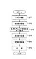
図3は、本実施形態のX線CT装置1の動作を示すフローチャートである。本発明の撮像方法は、本実施形態のX線CT装置1を用いて行われる。 FIG. 3 is a flowchart showing the operation of the
まず、使用者は、入力装置32を介してスカウト撮影を行う方向およびスカウト撮影を行う範囲を設定し、設定された範囲に基づいてスカウト撮影を行う(ST1)。本実施形態においては、たとえば、被検体のサジタル面のスカウト画像が生成される。 First, the user sets a direction for performing scout shooting and a range for performing scout shooting via the
中央処理装置31は、設定された条件に基づいて所定の範囲および方向に被検体を走査するように走査ガントリ2を制御する。このとき、たとえば、走査ガントリ2は、回転させずにX線管21および検出器アレイ23を一定の位置のまま被検体の体軸方向に移動して走査する。検出器アレイ23は、得られたデータをデータ収集部24を介して中央処理装置31に出力する。中央処理装置31は、得られたデータに基づいてスカウト画像を生成し、表示装置33に出力する。 The
次に、使用者は表示装置33に表示された被検体のスカウト画像を観察し、走査条件の設定を行う(ST2)。 Next, the user observes the scout image of the subject displayed on the
使用者は、たとえば、入力装置32を用いて走査開始位置、走査終了位置、画像生成間隔およびスライス厚などを入力する。中央処理装置31の管電流値設定部36は、スカウト画像の投影データおよび入力装置32を介して入力された上記の走査条件を参照して管電流値を算出する。中央処理装置31は、入力された走査条件および算出された管電流値を表示装置33に出力する。
また、使用者は、1回の走査あるいは1回転中において照射されるX線の吸収線量および照射幅などの許容値を入力装置32を介して許容範囲設定部38に入力する。上記のX線の吸収線量および照射幅は、撮影部位などによって決定される。さらに、使用者は、撮像範囲や画像の再構成条件などを同時に設定する。For example, the user inputs a scan start position, a scan end position, an image generation interval, a slice thickness, and the like using the
In addition, the user inputs allowable values such as the absorbed dose and irradiation width of X-rays irradiated during one scan or one rotation to the allowable
次に、表示装置33は使用者によって入力された走査条件および中央処理装置31によって算出された管電流値データを表示する(ST3)。 Next, the
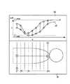
図4は、表示装置33におけるスカウト画像SIおよび管電流値データIGの表示の一例を示す概略図である。 FIG. 4 is a schematic diagram illustrating an example of display of the scout image SI and the tube current value data IG on the
図4に示すように、ステップST1において撮影された被検体のスカウト画像SIに画像生成位置Z1〜Zmがスカウト画像SIに対応させて表示されている。
また、画像生成位置Z1〜Zmに対応するようにスカウト画像SI上に、1回の走査における走査方向に連続する管電流値が縦軸に電流値I、横軸に距離dを示すグラフとして表示されている。ここで、1回の走査は、X線管21においてX線がオンされてからオフされるまでとする。なお、本実施形態において、走査方向は被検体の体軸方向と平行な方向とする。さらに、グラフには、1回の走査において変化する管電流値の最大値maxおよび最小値min、および走査ガントリ2が1回転する間に変化する管電流値の最大値a1および最小値a2が表示される。ここで、走査ガントリ2は、走査方向、つまり、被検体の体軸方向と直交する方向に回転する。
ここで、使用者がグラフ上の任意の位置あるいは任意の画像生成位置を選択すると、中央処理装置31の吸収線量・照射幅算出部39は、予め設定された許容範囲および選択された位置の管電流値などに基づいて走査ガントリ2の1回転ごとの吸収線量および照射幅を算出して、算出された値を表示装置33に出力する。その結果、使用者は、吸収線量および照射幅を確認することができる。As shown in FIG. 4, the image generation positions Z1 to Zm are displayed in correspondence with the scout image SI in the scout image SI of the subject imaged in step ST1.
Further, the tube current value continuous in the scanning direction in one scan is displayed on the scout image SI as a graph indicating the current value I on the vertical axis and the distance d on the horizontal axis so as to correspond to the image generation positions Z1 to Zm. Has been. Here, one scan is performed after the X-ray is turned on in the
Here, when the user selects an arbitrary position on the graph or an arbitrary image generation position, the absorbed dose / irradiation
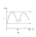
図5は、走査ガントリの回転方向における管電流値データの表示の一例を示す概略図である。縦軸は管電流値Iを示し、横軸は、たとえば、回転角度degを示す。ここで、被検体の垂直方向にX線管21からX線を照射する状態を0度とする。 FIG. 5 is a schematic diagram showing an example of display of tube current value data in the rotation direction of the scanning gantry. The vertical axis represents the tube current value I, and the horizontal axis represents, for example, the rotation angle deg. Here, the state of X-ray irradiation from the
図5は、たとえば、使用者が所定の画像生成位置、図4に示す画像位置Znを選択することによって表示装置の一部に表示される。
画像位置Znにおける管電流値Iは、走査ガントリ2が1回転する間において0度および180度近傍において低く設定され、90度および270度近傍において高く設定されている。これは、たとえば、被検体の体軸と直交する被検体の断面を楕円と見なしたときに、楕円の短軸方向と長軸方向においてX線吸収率が異なることに起因する。また、1回転中の最大値a1および最小値a2も表示される。さらに、使用者が、図5に示すグラフの任意の位置を選択すると、中央処理装置31の吸収線量・照射幅算出部39は、図4および図5に示す管電流値の値および予め設定された許容範囲に基づいて、吸収線量および照射線幅の最適な値を算出し、表示装置33に出力する。
なお、本発明の表示ステップの一実施態様が、ステップST3に相当する。5 is displayed on a part of the display device when the user selects a predetermined image generation position, for example, the image position Zn shown in FIG.
The tube current value I at the image position Zn is set low in the vicinity of 0 degrees and 180 degrees while the scanning gantry 2 rotates once, and is set high in the vicinity of 90 degrees and 270 degrees. This is because, for example, when the cross section of the subject orthogonal to the body axis of the subject is regarded as an ellipse, the X-ray absorption rate differs between the short axis direction and the long axis direction of the ellipse. In addition, the maximum value a1 and the minimum value a2 during one rotation are also displayed. Further, when the user selects an arbitrary position in the graph shown in FIG. 5, the absorbed dose / irradiation
An embodiment of the display step of the present invention corresponds to step ST3.
次に、必要に応じて走査位置を調整する(ST4)。
使用者は、入力装置32を介して表示装置33に表示された走査開始位置、走査終了位置および画像生成間隔などを必要に応じて調整する。また、たとえば、使用者はカーソルなどを用いて、図4に示す任意の画像生成位置を選択し、移動させてもよい。あるいは、使用者は、入力装置32から走査開始位置などの数値を入力する。Next, the scanning position is adjusted as necessary (ST4).
The user adjusts the scanning start position, the scanning end position, the image generation interval, and the like displayed on the
次に、算出され表示された管電流値を調整する(ST5)。 Next, the calculated and displayed tube current value is adjusted (ST5).
図6は、走査ガントリの回転方向における管電流値と回転角度の関係を示すグラフである。 FIG. 6 is a graph showing the relationship between the tube current value and the rotation angle in the rotation direction of the scanning gantry.
たとえば、使用者は、表示装置33上において、カーソルなどを用いて図5に示す管電流値のグラフi1の任意の点を選択して、所定の値になるように移動させる。ここでは、被検体の正面および背面からX線を照射する角度、つまり、0度および180度近傍から照射されるX線強度は低く、被検体の横方向から、つまり、90度および270度近傍から照射されるX線強度は高い。そのため、使用者は、たとえば、これらのX線強度の異なる角度へ移行する際の管電流値が小さくなるように調整する。
その結果、図5に示す算出された管電流値のグラフi1は、図6に示すグラフi2に調整される。このため、算出された管電流値と比較して、図6において斜線で示す領域r1に相当するX線の照射量を低減することができる。上記の低減率の算出は、表示装置33から出力されたデータに基づいて中央処理装置31の低減率算出部37において行われる。For example, the user selects an arbitrary point on the tube current value graph i1 shown in FIG. 5 on the
As a result, the calculated tube current value graph i1 shown in FIG. 5 is adjusted to the graph i2 shown in FIG. Therefore, compared with the calculated tube current value, the X-ray irradiation dose corresponding to the region r1 indicated by the oblique line in FIG. 6 can be reduced. The calculation of the reduction rate is performed in the reduction
また、使用者は、グラフ中に表示された最大値a1および最小値a2を示す破線を上下に移動させて管電流値を調整することもできる。さらに、グラフ上の任意の点を指定したのちに、入力装置32において数値を入力してもよい。中央処理装置31の吸収線量・照射波算出部39は、調整された管電流値および予め設定された許容範囲に基づいて適切な吸収線量および照射幅を算出する。使用者が調整された管電流値のグラフの任意の位置を選択すると、中央処理装置31は算出された吸収線量および照射幅を表示装置33に表示する。
調整が終了すると、使用者は、入力装置32から調整完了の指令を中央処理装置31に入力する。使用者は表示された吸収線量および管電流値などの値を確認した後に走査を開始することができる。
なお、本発明の調整ステップの一実施態様が、ステップST5に相当する。Further, the user can adjust the tube current value by moving the broken lines indicating the maximum value a1 and the minimum value a2 displayed in the graph up and down. Furthermore, after specifying an arbitrary point on the graph, a numerical value may be input by the
When the adjustment is completed, the user inputs an adjustment completion command from the
One embodiment of the adjustment step of the present invention corresponds to step ST5.
上記の設定は、使用者が表示装置33に表示された画像を観察しながら入力装置32を操作することにより設定され、中央処理装置31を介して記憶装置34に記憶される。 The above settings are set by the user operating the
次に、設定された走査条件に基づいて走査を行う(ST6)。 Next, scanning is performed based on the set scanning conditions (ST6).
中央処理装置31は、記憶装置34の上記の修正事項が追加されたプログラムに基づいて走査ガントリ2および撮影テーブル4に指令を送る。その結果、走査ガントリ2は、設定された走査速度に基づいて、所定の位置に位置づけられた被検体を体軸と直交する方向に回転しながら走査開始位置から走査終了位置までを体軸に沿って走査する。検出器アレイ23は、検出された投影データをデータ収集部24を介して中央処理装置31に出力する。中央処理装置31は、入力されたデータを記憶装置34に記憶する。なお、本発明において走査方法は、アキシャルスキャンおよびヘリカルスキャンのいずれも適用することができる。
ここで、本発明の走査ステップの一実施態様がステップST6に相当する。The
Here, one embodiment of the scanning step of the present invention corresponds to step ST6.
その後、中央処理装置31は、ステップST6において得られた投影データを用いて、設定された条件に基づいて再構成処理を行う。 Thereafter, the
中央処理装置31は、記憶装置34に記憶された逆投影などのプログラムなどに基づいて再構成処理を行う。中央処理装置31は、上記の設定された画像生成位置における断層像を表示装置33に表示する。 The
なお、管電流値の表示方法は、上記の方法に限定されない。たとえば、下記に示すような方法によって表示されてもよい。 In addition, the display method of a tube current value is not limited to said method. For example, you may display by the method as shown below.
図7は、走査ガントリの回転平面における管電流値の他の例を示すグラフである。図7に示すように、縦軸および横軸において角度をとり、それぞれの回転角度における管電流値を示す。図7は、たとえば、座標中心に近いほど管電流値が小さく、座標中心から遠ざかるほど管電流値が大きいことを示している。 FIG. 7 is a graph showing another example of the tube current value in the rotation plane of the scanning gantry. As shown in FIG. 7, the vertical axis and the horizontal axis are angled to indicate the tube current value at each rotation angle. FIG. 7 shows that, for example, the tube current value is smaller as it is closer to the coordinate center, and the tube current value is larger as it is farther from the coordinate center.
図8は、走査ガントリの回転平面における管電流値の他の例を示すグラフである。図8に示すように、管電流値の大きさを棒グラフで示し、それぞれの角度における管電流値を示す。 FIG. 8 is a graph showing another example of the tube current value in the rotation plane of the scanning gantry. As shown in FIG. 8, the magnitude of the tube current value is shown by a bar graph, and the tube current value at each angle is shown.
また、図示は省略するが、管電流値を色の濃淡などで示し、それぞれの角度における管電流値を示してもよい。 Although not shown, the tube current value may be indicated by color shading or the like, and the tube current value at each angle may be indicated.
本実施形態のX線CT装置によれば、走査方向および走査ガントリの回転方向におけるX線管から照射されるX線を制御する制御値、たとえば、管電流値を画像生成位置と対応させて表示装置に表示することにより、使用者の操作性が向上する。また、走査方向および走査ガントリの回転方向における連続する管電流値を選択的に表示するので、1回転中の管電流値を変えて走査を行う場合にも回転中の管電流値などを確認することができる。 また、表示装置に表示された管電流値を使用者が微調整することができ、微調整することによって低減された照射量を確認することができる。このような照射量の低減率などを視覚的に捉えるので、操作性の向上とともに照射量の低減を容易に確認することができる。
さらに、ヘリカルスキャンなどのように画像と回転が一致しない場合などにおいても、走査ガントリの回転方向における連続する管電流値を確認することができるので、画像に対応する管電流値の確認をすることができる。なお、管電流値に付随する低減率、吸収線量および照射幅などの情報も同時に表示することにより、作業効率が向上する。According to the X-ray CT apparatus of the present embodiment, a control value for controlling X-rays emitted from the X-ray tube in the scanning direction and the rotation direction of the scanning gantry, for example, a tube current value is displayed in correspondence with the image generation position. By displaying on the device, the operability for the user is improved. In addition, since continuous tube current values in the scanning direction and the rotation direction of the scanning gantry are selectively displayed, the tube current value during rotation is also confirmed when scanning is performed by changing the tube current value during one rotation. be able to. Further, the user can finely adjust the tube current value displayed on the display device, and the irradiation dose reduced by fine adjustment can be confirmed. Since such a reduction rate of the irradiation amount is visually grasped, it is possible to easily confirm the reduction in the irradiation amount as well as the operability.
Furthermore, even when the image and rotation do not match, such as in helical scanning, the continuous tube current value in the rotation direction of the scanning gantry can be confirmed, so the tube current value corresponding to the image must be confirmed. Can do. The work efficiency is improved by simultaneously displaying information such as the reduction rate, absorbed dose, and irradiation width associated with the tube current value.
本発明の放射線断層撮像装置は、上記の実施形態に限定されない。
たとえば、制御値は、管電流値に限定されず、放射線量を制御するパラメータであればよい。また、吸収線量および照射幅に許容範囲を設定してそれぞれ算出しているが、いずれか一方のみを算出してもよい。さらに1回の走査ごとに上記の設定を変更することもできる。またさらに、被検体の走査時に走査ガントリを移動させて走査を行っているが、撮影テーブルを体軸方向に移動させて走査を行ってもよい。
その他、本発明の要旨を逸脱しない範囲で種々の変更が可能である。The radiation tomographic imaging apparatus of the present invention is not limited to the above embodiment.
For example, the control value is not limited to the tube current value, and may be a parameter that controls the radiation dose. Moreover, although the allowable ranges are set for the absorbed dose and the irradiation width, respectively, the calculation is performed, but only one of them may be calculated. Further, the above setting can be changed for each scan. Furthermore, although scanning is performed by moving the scanning gantry during scanning of the subject, scanning may be performed by moving the imaging table in the body axis direction.
In addition, various modifications can be made without departing from the scope of the present invention.
1・・・X線CT装置
2・・・走査ガントリ
3・・・操作コンソール
4・・・撮影テーブル
21・・・X線管
22・・・コリメータ
23・・・検出器アレイ
24・・・データ収集部
25・・・X線コントローラ
26・・・コリメータコントローラ
27・・・回転部
28・・・回転コントローラ
29・・・ボア
31・・・中央処理装置
32・・・入力装置
33・・・表示装置
34・・・記憶装置
35・・・管電流値算出部
36・・・調整部
37・・・低減率算出部
38・・・許容範囲設定部
39・・・吸収線量・照射幅算出部DESCRIPTION OF
Claims (9)
Translated fromJapanese前記放射線源から照射される放射線量を制御する制御値を算出する制御値算出手段と、
前記被検体の頭部と足先とを結ぶ体軸方向に応じた制御値を前記被検体の頭部と足先とを結ぶ体軸方向における画像生成位置に対応させてグラフ表示すると共に、当該画像生成位置における前記制御値の変化をグラフ表示する表示手段と
を有する放射線断層撮像装置。A radiation source, and a radiation detector disposed so as to face the radiation source through the subject, wherein at least one of the radiation source and the radiation detector is rotated around the subject. Scanning means for scanning the subject;
Control value calculating means for calculating a control value for controlling the radiation dose emitted from the radiation source;
The control value according to the body axis direction connecting the head and the toe of the subject is displayed in a graph corresponding to the image generation position in the body axis direction connecting the head and the toe of the subject, and A radiation tomography apparatus comprising: display means for displaying a graph of the change in the control value at the image generation position.
請求項1に記載の放射線断層撮像装置。The display means is a graph in which a control value corresponding to a body axis direction connecting the head and toes of the subject is associated with an image generation position in a body axis direction connecting the head and toes of the subject. 2. The change in the control value at the image generation position is indicated by displaying a display of a maximum value and a minimum value of the control value according to the body axis direction at the image generation position. Radiation tomography system.
請求項1または2に記載の放射線断層撮影装置。The display means displays a second screen for displaying a change in the control value during one rotation at the image generation position in a graph corresponding to the rotation angle in a graph corresponding to the image generation position in the body axis direction. The radiation tomography apparatus according to claim 1, wherein the radiation tomography apparatus is displayed on a second screen different from the screen.
請求項3に記載の放射線断層撮影装置。The radiation tomography apparatus according to claim 3, wherein the display unit displays the second screen by selecting the image generation position on the graph of the first screen.
請求項1〜4のいずれか一項に記載の放射線断層撮像装置。A graph in which the control value corresponding to the body axis direction connecting the head and the toe of the subject is associated with the image generation position in the body axis direction connecting the head and the toe of the subject is shown on the vertical axis. The radiation tomography apparatus according to any one of claims 1 to 4, which is a graph showing a control value and a distance on a horizontal axis.
請求項1〜5のいずれか一項に記載の放射線断層撮像装置。The radiation tomography apparatus according to any one of claims 1 to 5, wherein the display unit further displays a scout image and the image generation position on the scout image.
をさらに有する請求項1〜6のいずれか一項に記載の放射線断層撮像装置。The radiation tomography apparatus according to claim 1, further comprising an adjustment unit that adjusts the control value displayed on the display unit.
その後調整された前記制御値とを比較して、低減率を算出する低減率算出手段と
をさらに有する請求項7に記載の放射線断層撮像装置。The radiation tomographic imaging apparatus according to claim 7, further comprising a reduction rate calculation unit that calculates a reduction rate by comparing the control value displayed on the display unit with the control value adjusted thereafter.
請求項1〜8のいずれか一項に記載の放射線断層撮像装置。The radiation tomographic imaging apparatus according to claim 1, wherein the scanning unit controls the radiation dose using a tube current value as the control value.
Priority Applications (1)
| Application Number | Priority Date | Filing Date | Title |
|---|---|---|---|
| JP2010153564AJP5642439B2 (en) | 2010-07-06 | 2010-07-06 | Radiation tomography system |
Applications Claiming Priority (1)
| Application Number | Priority Date | Filing Date | Title |
|---|---|---|---|
| JP2010153564AJP5642439B2 (en) | 2010-07-06 | 2010-07-06 | Radiation tomography system |
Related Parent Applications (1)
| Application Number | Title | Priority Date | Filing Date |
|---|---|---|---|
| JP2007098091ADivisionJP2007181737A (en) | 2007-04-04 | 2007-04-04 | Radiation tomographic apparatus |
Publications (2)
| Publication Number | Publication Date |
|---|---|
| JP2010246970Atrue JP2010246970A (en) | 2010-11-04 |
| JP5642439B2 JP5642439B2 (en) | 2014-12-17 |
Family
ID=43309948
Family Applications (1)
| Application Number | Title | Priority Date | Filing Date |
|---|---|---|---|
| JP2010153564AExpired - LifetimeJP5642439B2 (en) | 2010-07-06 | 2010-07-06 | Radiation tomography system |
Country Status (1)
| Country | Link |
|---|---|
| JP (1) | JP5642439B2 (en) |
Cited By (2)
| Publication number | Priority date | Publication date | Assignee | Title |
|---|---|---|---|---|
| JP2015500119A (en)* | 2011-12-14 | 2015-01-05 | コーニンクレッカ フィリップス エヌ ヴェ | Real-time feedback to prevent high-dose C-arch geometry |
| JP2015123302A (en)* | 2013-12-27 | 2015-07-06 | 株式会社東芝 | Medical image diagnostic apparatus and image processing apparatus |
Citations (9)
| Publication number | Priority date | Publication date | Assignee | Title |
|---|---|---|---|---|
| JPH05220135A (en)* | 1992-02-14 | 1993-08-31 | Toshiba Corp | Ct device |
| JPH08206107A (en)* | 1994-09-06 | 1996-08-13 | General Electric Co <Ge> | X-ray volume reducing method |
| JPH09244618A (en)* | 1996-03-13 | 1997-09-19 | Toshiba Corp | Trend graph display method and display device thereof |
| JP2001276040A (en)* | 2000-04-03 | 2001-10-09 | Hitachi Medical Corp | X-ray ct device |
| JP2002177261A (en)* | 2000-12-07 | 2002-06-25 | Ge Medical Systems Global Technology Co Llc | Ct system and its operation console, and control method and memory medium |
| JP2002263097A (en)* | 2001-03-09 | 2002-09-17 | Hitachi Medical Corp | Radiographic tomograph |
| JP2003010168A (en)* | 2001-06-28 | 2003-01-14 | Toshiba Corp | X-ray CT system |
| JP2003199739A (en)* | 2001-10-22 | 2003-07-15 | Toshiba Corp | X-ray computed tomography apparatus and x-ray computed tomography method |
| JP2003290214A (en)* | 2002-03-27 | 2003-10-14 | Ge Medical Systems Global Technology Co Llc | Transmitted x-ray data acquisition apparatus and x-ray tomograph |
- 2010
- 2010-07-06JPJP2010153564Apatent/JP5642439B2/ennot_activeExpired - Lifetime
Patent Citations (9)
| Publication number | Priority date | Publication date | Assignee | Title |
|---|---|---|---|---|
| JPH05220135A (en)* | 1992-02-14 | 1993-08-31 | Toshiba Corp | Ct device |
| JPH08206107A (en)* | 1994-09-06 | 1996-08-13 | General Electric Co <Ge> | X-ray volume reducing method |
| JPH09244618A (en)* | 1996-03-13 | 1997-09-19 | Toshiba Corp | Trend graph display method and display device thereof |
| JP2001276040A (en)* | 2000-04-03 | 2001-10-09 | Hitachi Medical Corp | X-ray ct device |
| JP2002177261A (en)* | 2000-12-07 | 2002-06-25 | Ge Medical Systems Global Technology Co Llc | Ct system and its operation console, and control method and memory medium |
| JP2002263097A (en)* | 2001-03-09 | 2002-09-17 | Hitachi Medical Corp | Radiographic tomograph |
| JP2003010168A (en)* | 2001-06-28 | 2003-01-14 | Toshiba Corp | X-ray CT system |
| JP2003199739A (en)* | 2001-10-22 | 2003-07-15 | Toshiba Corp | X-ray computed tomography apparatus and x-ray computed tomography method |
| JP2003290214A (en)* | 2002-03-27 | 2003-10-14 | Ge Medical Systems Global Technology Co Llc | Transmitted x-ray data acquisition apparatus and x-ray tomograph |
Cited By (2)
| Publication number | Priority date | Publication date | Assignee | Title |
|---|---|---|---|---|
| JP2015500119A (en)* | 2011-12-14 | 2015-01-05 | コーニンクレッカ フィリップス エヌ ヴェ | Real-time feedback to prevent high-dose C-arch geometry |
| JP2015123302A (en)* | 2013-12-27 | 2015-07-06 | 株式会社東芝 | Medical image diagnostic apparatus and image processing apparatus |
Also Published As
| Publication number | Publication date |
|---|---|
| JP5642439B2 (en) | 2014-12-17 |
Similar Documents
| Publication | Publication Date | Title |
|---|---|---|
| JP2005185718A (en) | Radiation tomography apparatus and imaging method | |
| CN100393281C (en) | X-ray computed tomography device | |
| WO2010101208A1 (en) | X-ray ct device and tomography method | |
| JP6342437B2 (en) | Radiation tomography system and control program therefor | |
| JPWO2009020136A1 (en) | X-ray CT system | |
| JP3909059B2 (en) | Radiation tomographic imaging apparatus and imaging method using the same | |
| JP2008113960A (en) | Radiographic apparatus | |
| JP6509198B2 (en) | X-ray CT system | |
| WO2018235393A1 (en) | X-ray CT apparatus and X-ray irradiation condition setting method | |
| JP4300126B2 (en) | X-ray CT apparatus and imaging method | |
| JP2005080839A (en) | Radiation tomograph apparatus and radiation tomography method | |
| JP5642439B2 (en) | Radiation tomography system | |
| JP2007181737A (en) | Radiation tomographic apparatus | |
| JP2010269081A (en) | X-ray diagnostic imaging equipment | |
| JP5111834B2 (en) | Radiography equipment | |
| JP5597364B2 (en) | X-ray computed tomography apparatus and imaging control program | |
| JP6552792B2 (en) | X-ray computed tomography system | |
| JP6169831B2 (en) | X-ray computed tomography system | |
| JP2011245048A (en) | X-ray ct apparatus | |
| JP4381099B2 (en) | Radiation tomography equipment | |
| JP3796378B2 (en) | X-ray CT system | |
| JP4648355B2 (en) | Tube current adjusting method and apparatus, and X-ray CT apparatus | |
| US11399795B2 (en) | X-ray CT apparatus and imaging control method | |
| JP5220580B2 (en) | X-ray CT system | |
| JP2006255241A (en) | Radiography method and radiography equipment |
Legal Events
| Date | Code | Title | Description |
|---|---|---|---|
| A131 | Notification of reasons for refusal | Free format text:JAPANESE INTERMEDIATE CODE: A131 Effective date:20120529 | |
| A521 | Request for written amendment filed | Free format text:JAPANESE INTERMEDIATE CODE: A523 Effective date:20120823 | |
| A02 | Decision of refusal | Free format text:JAPANESE INTERMEDIATE CODE: A02 Effective date:20130409 | |
| A521 | Request for written amendment filed | Free format text:JAPANESE INTERMEDIATE CODE: A523 Effective date:20130807 | |
| A911 | Transfer to examiner for re-examination before appeal (zenchi) | Free format text:JAPANESE INTERMEDIATE CODE: A911 Effective date:20130814 | |
| A912 | Re-examination (zenchi) completed and case transferred to appeal board | Free format text:JAPANESE INTERMEDIATE CODE: A912 Effective date:20130920 | |
| A61 | First payment of annual fees (during grant procedure) | Free format text:JAPANESE INTERMEDIATE CODE: A61 Effective date:20141029 | |
| R150 | Certificate of patent or registration of utility model | Ref document number:5642439 Country of ref document:JP Free format text:JAPANESE INTERMEDIATE CODE: R150 | |
| R250 | Receipt of annual fees | Free format text:JAPANESE INTERMEDIATE CODE: R250 | |
| R250 | Receipt of annual fees | Free format text:JAPANESE INTERMEDIATE CODE: R250 | |
| R250 | Receipt of annual fees | Free format text:JAPANESE INTERMEDIATE CODE: R250 | |
| R250 | Receipt of annual fees | Free format text:JAPANESE INTERMEDIATE CODE: R250 | |
| R250 | Receipt of annual fees | Free format text:JAPANESE INTERMEDIATE CODE: R250 | |
| R250 | Receipt of annual fees | Free format text:JAPANESE INTERMEDIATE CODE: R250 | |
| EXPY | Cancellation because of completion of term |