JP2010246087A - Magnetic circuit for speaker and electrodynamic speaker using the same - Google Patents
Magnetic circuit for speaker and electrodynamic speaker using the sameDownload PDFInfo
- Publication number
- JP2010246087A JP2010246087AJP2009290434AJP2009290434AJP2010246087AJP 2010246087 AJP2010246087 AJP 2010246087AJP 2009290434 AJP2009290434 AJP 2009290434AJP 2009290434 AJP2009290434 AJP 2009290434AJP 2010246087 AJP2010246087 AJP 2010246087A
- Authority
- JP
- Japan
- Prior art keywords
- magnet
- speaker
- magnetic circuit
- radius
- pole
- Prior art date
- Legal status (The legal status is an assumption and is not a legal conclusion. Google has not performed a legal analysis and makes no representation as to the accuracy of the status listed.)
- Pending
Links
Images


Landscapes
- Audible-Bandwidth Dynamoelectric Transducers Other Than Pickups (AREA)
Abstract
Translated fromJapaneseDescription
Translated fromJapanese本発明は、スピーカー用磁気回路、および、これを用いた動電型スピーカーに関し、特に、同心円状に配置される複数のマグネットを含むスピーカー用磁気回路に関する。 The present invention relates to a speaker magnetic circuit and an electrodynamic speaker using the same, and more particularly to a speaker magnetic circuit including a plurality of magnets arranged concentrically.
大口径のスピーカー振動板を備える大型の動電型スピーカーにおいては、磁気回路を大型化して磁気空隙での磁束密度を高め、動電型スピーカーの効率を高くするとともに、大きな音量の音声を再生可能にしようとするものがある。大口径の動電型スピーカーは、スピーカー振動板を含む振動系の重量が重くなるので、再生能率を高めるには、磁気回路の磁気空隙での磁束密度を高める必要がある。磁気回路の磁気空隙での磁束密度を高めるには、磁気空隙の間隔を狭くする、保磁力の高いマグネットを使用する、あるいは、マグネットを大型化する、といった手段がある。 For large electrodynamic speakers with large-diameter speaker diaphragms, the magnetic circuit can be enlarged to increase the magnetic flux density in the magnetic air gap, increasing the efficiency of the electrodynamic speakers and reproducing loud sound. There is something to try. A large-diameter electrodynamic speaker increases the weight of the vibration system including the speaker diaphragm. Therefore, in order to increase the reproduction efficiency, it is necessary to increase the magnetic flux density in the magnetic gap of the magnetic circuit. In order to increase the magnetic flux density in the magnetic gap of the magnetic circuit, there are means such as narrowing the gap of the magnetic gap, using a magnet with high coercive force, or increasing the size of the magnet.
大型のスピーカー用磁気回路では、外磁型として用いる場合に起磁力が大きく、安価なドーナツ状(環状)のフェライト磁石を、磁気回路に使用する場合がある。動電型スピーカーでは、磁気回路が大型化するにつれて、自ずとマグネットも大型化するので、コストの面で不利な点がある。したがって、従来には、これらの問題を解決するために様々なスピーカー用磁気回路、および、これを用いた動電型スピーカーが提案されている。 In a large-sized speaker magnetic circuit, a donut-shaped (annular) ferrite magnet having a large magnetomotive force when used as an external magnet type may be used for the magnetic circuit. The electrodynamic speaker has a disadvantage in terms of cost because the magnet naturally increases in size as the magnetic circuit increases in size. Therefore, in order to solve these problems, various magnetic circuits for speakers and electrodynamic speakers using the same have been proposed.
従来の平面振動板を備える動電型スピーカーでは、単一の磁石で2つのドライバユニットを構成する磁気回路において、センターポールを中心にその周囲にヨークを介して同心的に設けたリングポールをもつポール体と、センターポールと同心円上に等配され、各ポールとエアーギャップをもつプレートを有する複数個の磁石と、各磁石間に充填されたシール剤とを備え、各エアーギャップ中にそれぞれ異なった振動板のボイスコイルが位置できるように構成した磁気回路がある。(特許文献1)。 In an electrodynamic speaker having a conventional planar diaphragm, a magnetic circuit in which two driver units are constituted by a single magnet has a ring pole concentrically provided around a center pole via a yoke. A pole body, a plurality of magnets having a plate concentric with the center pole and having a plate with each pole and an air gap, and a sealant filled between the magnets, and different in each air gap There is a magnetic circuit configured so that the voice coil of the diaphragm can be positioned. (Patent Document 1).
また、従来の動電型スピーカーでは、マルチ−フェライトマグネットの磁気回路であって、円形のマグネットに続いているポールのアンダープレートおよびプレートの外周縁部が、「花弁」のような形態を有する磁気回路を備えるものがある。フェライトマグネットは、希土類磁石でも良く、その磁気回路の性能と効率を高めて、同時に、コストを削減して、再生能力を改善しようとするものがある。(特許文献2)。 In addition, in the conventional electrodynamic speaker, the magnetic circuit is a multi-ferrite magnet, in which the pole under plate following the circular magnet and the outer peripheral edge of the plate have a form like a “petal”. Some have a circuit. Ferrite magnets may be rare earth magnets, some of which attempt to increase the performance and efficiency of their magnetic circuits, while simultaneously reducing costs and improving readability. (Patent Document 2).
また、出願人が権利者である意匠登録されたスピーカーでは、内磁型の磁気回路を備える動電型スピーカーであって、フレーム背面部および磁気回路の中心に貫通孔を備え、磁気回路を構成する複数の円形磁石の一部が、貫通孔に円弧状に突出しているものがある。(特許文献3、特許文献4)。 In addition, the design-registered speaker whose applicant is the right holder is an electrodynamic speaker provided with an inner-magnet-type magnetic circuit, and has a through-hole at the back of the frame and at the center of the magnetic circuit to constitute the magnetic circuit. Some of the plurality of circular magnets project in a circular arc shape in the through hole. (
しかしながら、従来技術の動電型スピーカーの磁気回路では、いずれも充分ではない。特許文献1および2に記載のスピーカー磁気回路のように、同心円状に配置される複数の円柱状のマグネットを使用する場合には、コストの制限を考慮してマグネットを選定しなければならない。特に、複数のマグネットのそれぞれを、複数のマグネットを多段に積み重ねて、磁気回路を構成する場合もある。大型のスピーカー用磁気回路では、このようなコストの制限の下でも、磁気空隙の磁束密度を最も高める必要がある、という問題がある。また、特許文献3または4に記載の内磁型の磁気回路の場合についても、同様の問題がある。 However, none of the magnetic circuits of conventional electrodynamic loudspeakers is sufficient. When using a plurality of cylindrical magnets arranged concentrically like the speaker magnetic circuits described in
本発明は、上記の従来技術が有する問題を解決するためになされたものであり、その目的は、同心円状に配置される複数のマグネットを使用する動電型スピーカー用の磁気回路に関し、大型の磁気回路であっても低コストであり、能率が高くて再生音圧レベルも十分高く、再生音声品質に優れる動電型スピーカーを実現するスピーカー用磁気回路を提供することにある。 The present invention has been made to solve the above-described problems of the prior art, and an object thereof is related to a magnetic circuit for an electrodynamic speaker that uses a plurality of magnets arranged concentrically. An object of the present invention is to provide a magnetic circuit for a speaker that realizes an electrodynamic speaker that is low in cost, has high efficiency, has a sufficiently high reproduction sound pressure level, and is excellent in reproduction sound quality.
本発明のスピーカー用磁気回路は、センターポールを中央に配置するアンダープレートを有するポールと、その内径側端面とセンターポールの側面との間に磁気空隙を形成する略円環状のトッププレートと、アンダープレートおよびトッププレートの間に狭持されて同心円状に配置される複数のマグネット組と、を備え、複数のマグネット組のそれぞれが、トッププレートに連結する第1マグネットと、アンダープレートに連結する第2マグネットと、を含み、同心円状に配置される複数の第1マグネットの内周端側位置を規定する第1半径r1が、同心円状に配置される複数の第2マグネットの内周端側位置を規定する第2半径r2よりも小さくなるように、それぞれのマグネット組が構成されている。 A magnetic circuit for a speaker according to the present invention includes a pole having an under plate in which a center pole is arranged at the center, a substantially annular top plate that forms a magnetic gap between an inner diameter side end surface and a side surface of the center pole, A plurality of magnet sets sandwiched between the plate and the top plate and arranged concentrically, each of the plurality of magnet sets being connected to the top plate and the first plate connected to the under plate The first radius r1 that defines the inner peripheral end side position of the plurality of first magnets arranged concentrically, including the two magnets, and the inner peripheral end side position of the plurality of second magnets arranged concentrically Each magnet set is configured to be smaller than a second radius r2 that defines
または、本発明のスピーカー用磁気回路は、センターポールを中央に配置する円筒壁部を有するヨークと、その外径側端面とヨークの円筒壁部の内側面との間に磁気空隙を形成する略円環状のトップポールと、センターポールおよびトップポールの間に狭持されて同心円状に配置される複数のマグネット組と、を備え、複数のマグネット組のそれぞれが、トップポールに連結する第1マグネットと、ヨークのセンターポールに連結する第2マグネットと、を含み、同心円状に配置される複数の第1マグネットの外周端側位置を規定する第1半径R1が、同心円状に配置される複数の第2マグネットの外周端側位置を規定する第2半径R2よりも大きくなるように、それぞれのマグネット組が構成されている。 Alternatively, the magnetic circuit for a speaker according to the present invention includes a yoke having a cylindrical wall portion in which the center pole is arranged at the center, and a magnetic gap formed between the outer diameter side end surface and the inner surface of the cylindrical wall portion of the yoke. A first magnet that includes an annular top pole and a plurality of magnet sets that are concentrically disposed between the center pole and the top pole, and each of the plurality of magnet sets is coupled to the top pole. And a second magnet coupled to the center pole of the yoke, and a plurality of first radii R1 defining the outer peripheral end positions of the plurality of first magnets arranged concentrically are arranged concentrically. Each magnet set is configured to be larger than the second radius R2 that defines the position of the outer peripheral end of the second magnet.
好ましくは、本発明のスピーカー用磁気回路は、第1マグネットおよび第2マグネットが、同一寸法の略円筒形状を有する希土類磁石である。 Preferably, in the magnetic circuit for a speaker according to the present invention, the first magnet and the second magnet are rare earth magnets having a substantially cylindrical shape having the same dimensions.
また、好ましくは、本発明のスピーカー用磁気回路は、同心円状に隣り合う第1マグネット同士の間隔を規定する距離w1が、隣り合う第2マグネット同士の間隔を規定する距離w2と異なるように、それぞれのマグネット組が構成されている。 Preferably, in the speaker magnetic circuit of the present invention, the distance w1 defining the interval between the first magnets adjacent to each other in a concentric manner is different from the distance w2 defining the interval between the adjacent second magnets. Each magnet set is configured.
また、好ましくは、本発明のスピーカー用磁気回路は、トッププレートの外径側端面の半径rtが、第1マグネットの外周端側位置を規定する第3半径r3以下であり、アンダープレートの外径側端面の半径ruが、第2マグネットの外周端側位置を規定する第4半径r4以下である。 Preferably, in the magnetic circuit for a speaker according to the present invention, the radius rt of the outer diameter side end surface of the top plate is equal to or smaller than the third radius r3 that defines the outer peripheral end side position of the first magnet, and the outer diameter of the under plate. The radius ru of the side end surface is equal to or less than the fourth radius r4 that defines the outer peripheral end side position of the second magnet.
また、本発明の動電型スピーカーは、上記のスピーカー用磁気回路と、スピーカー振動板と、スピーカー振動板に連結する円筒形状のボイスコイルボビンと、ボイスコイルボビンに巻回されて磁気空隙に配置されるボイスコイルと、を備える。 The electrodynamic speaker according to the present invention is arranged in the magnetic gap wound around the voice coil bobbin, the cylindrical magnetic coil bobbin connected to the speaker magnetic circuit, the speaker diaphragm, and the speaker diaphragm. A voice coil.
以下、本発明の作用について説明する。 Hereinafter, the operation of the present invention will be described.
本発明のスピーカー用磁気回路は、センターポールを中央に配置するアンダープレートを有するポールと、その内径側端面とセンターポールの側面との間に磁気空隙を形成する略円環状のトッププレートと、アンダープレートおよびトッププレートの間に狭持されて同心円状に配置される複数のマグネット組と、を備える外磁型磁気回路である。または、本発明のスピーカー用磁気回路は、センターポールを中央に配置する円筒壁部を有するヨークと、その外径側端面とヨークの円筒壁部の内側面との間に磁気空隙を形成する略円環状のトップポールと、センターポールおよびトップポールの間に狭持されて同心円状に配置される複数のマグネット組と、を備える内磁型磁気回路である。したがって、本発明の動電型スピーカーは、このスピーカー用磁気回路と、スピーカー振動板と、スピーカー振動板に連結する円筒形状のボイスコイルボビンと、ボイスコイルボビンに巻回されて磁気空隙に配置されるボイスコイルと、を備えることで、再生音声品質に優れる動電型スピーカーを実現する。 A magnetic circuit for a speaker according to the present invention includes a pole having an under plate in which a center pole is arranged at the center, a substantially annular top plate that forms a magnetic gap between an inner diameter side end surface and a side surface of the center pole, And an outer magnet type magnetic circuit including a plurality of magnet sets sandwiched between a plate and a top plate and arranged concentrically. Alternatively, the magnetic circuit for a speaker according to the present invention includes a yoke having a cylindrical wall portion in which the center pole is arranged at the center, and a magnetic gap formed between the outer diameter side end surface and the inner surface of the cylindrical wall portion of the yoke. An internal magnet type magnetic circuit comprising an annular top pole and a plurality of magnet sets arranged concentrically between a center pole and a top pole. Therefore, the electrodynamic speaker of the present invention includes the speaker magnetic circuit, the speaker diaphragm, the cylindrical voice coil bobbin connected to the speaker diaphragm, and the voice wound around the voice coil bobbin and disposed in the magnetic gap. By providing a coil, an electrodynamic speaker with excellent reproduction sound quality is realized.
ここで、スピーカー用磁気回路は、複数のマグネット組のそれぞれが、トッププレートまたはトップポールに連結する第1マグネットと、ポールのアンダープレートまたはヨークのセンターポールに連結する第2マグネットと、を含む。つまり、マグネット組は、少なくとも2つのマグネットを積み上げて構成するものであり、好ましくは、第1マグネットおよび第2マグネットが、同一寸法の略円筒形状を有する希土類磁石である。したがって、スピーカー用磁気回路は、大型の磁気回路であっても小型のマグネットを利用することができるので、低コストを実現できる。 Here, the speaker magnetic circuit includes a first magnet coupled to the top plate or the top pole, and a second magnet coupled to the pole under plate or the center pole of the yoke, respectively. That is, the magnet set is configured by stacking at least two magnets. Preferably, the first magnet and the second magnet are rare earth magnets having a substantially cylindrical shape with the same dimensions. Therefore, since the speaker magnetic circuit can use a small magnet even if it is a large magnetic circuit, low cost can be realized.
そして、このスピーカー用磁気回路は、外磁型磁気回路の場合には、複数のマグネット組のそれぞれにおいて、同心円状に配置される複数の第1マグネットの内周端側位置を規定する第1半径r1が、同心円状に配置される複数の第2マグネットの内周端側位置を規定する第2半径r2よりも小さくなるように、それぞれのマグネット組が構成されている。また、第1マグネットおよび第2マグネットが、同一寸法の略円筒形状を有する希土類磁石である場合には、第1マグネットの内周端側位置を規定する第1半径r1が第2マグネットの内周端側位置を規定する第2半径r2よりも小さくなれば、同心円状に隣り合う第1マグネット同士の間隔を規定する距離w1が、隣り合う第2マグネット同士の間隔を規定する距離w2と異なり、距離w2よりも小さくなる。すなわち、同心円状に配置される第1マグネットが、第2マグネットよりも磁気空隙の近くなるように配置される。その結果、磁気空隙での磁束密度を、単に同一寸法のマグネットを積み上げる場合に比べて高くできるので、能率が高くて再生音圧レベルも十分な動電型スピーカーを実現できる。 When the speaker magnetic circuit is an external magnetic type magnetic circuit, the first radius defining the inner peripheral end side positions of the plurality of first magnets arranged concentrically in each of the plurality of magnet sets. Each magnet set is configured such that r1 is smaller than a second radius r2 that defines the positions of the inner peripheral ends of the plurality of second magnets arranged concentrically. Further, when the first magnet and the second magnet are rare earth magnets having a substantially cylindrical shape with the same dimensions, the first radius r1 that defines the inner peripheral end side position of the first magnet is the inner periphery of the second magnet. If the distance is smaller than the second radius r2 that defines the end position, the distance w1 that defines the interval between the first magnets that are concentrically adjacent to each other is different from the distance w2 that defines the interval between the adjacent second magnets. It becomes smaller than the distance w2. That is, the first magnet arranged concentrically is arranged so as to be closer to the magnetic gap than the second magnet. As a result, the magnetic flux density in the magnetic gap can be increased as compared with a case where magnets having the same dimensions are simply stacked, so that an electrodynamic speaker with high efficiency and sufficient reproduction sound pressure level can be realized.
具体的には、本発明のスピーカー用磁気回路は、トッププレートの外径側端面の半径rtが、第1マグネットの外周端側位置を規定する第3半径r3以下であり、アンダープレートの外径側端面の半径ruが、第2マグネットの外周端側位置を規定する第4半径r4以下であるようにするのが好ましい。 Specifically, in the magnetic circuit for a speaker of the present invention, the radius rt of the outer diameter side end surface of the top plate is equal to or smaller than the third radius r3 that defines the outer peripheral end side position of the first magnet, and the outer diameter of the under plate It is preferable that the radius ru of the side end face be equal to or smaller than the fourth radius r4 that defines the position of the outer peripheral end of the second magnet.
また、このスピーカー用磁気回路は、内磁型磁気回路の場合には、複数のマグネット組のそれぞれにおいて、同心円状に配置される複数の第1マグネットの外周端側位置を規定する第1半径R1が、同心円状に配置される複数の第2マグネットの外周端側位置を規定する第2半径R2よりも大きくなるように、それぞれのマグネット組が構成されている。すなわち、同心円状に隣り合う第1マグネット同士の間隔を規定する距離w1が、隣り合う第2マグネット同士の間隔を規定する距離w2と異なり、距離w2よりも大きくなり、同心円状に配置される第1マグネットが、第2マグネットよりも磁気空隙の近くなるように配置される。その結果、磁気空隙での磁束密度を、単に同一寸法のマグネットを積み上げる場合に比べて高くできるので、能率が高くて再生音圧レベルも十分な動電型スピーカーを実現できる。 In the case of the internal magnetic circuit, the speaker magnetic circuit has a first radius R1 that defines the positions of the outer peripheral ends of the plurality of first magnets arranged concentrically in each of the plurality of magnet sets. However, each magnet set is configured to be larger than the second radius R2 that defines the outer peripheral end side position of the plurality of second magnets arranged concentrically. That is, the distance w1 that defines the interval between the first magnets adjacent to each other in a concentric manner is different from the distance w2 that defines the interval between the adjacent second magnets, and is larger than the distance w2 and is arranged in a concentric manner. One magnet is arranged closer to the magnetic gap than the second magnet. As a result, the magnetic flux density in the magnetic gap can be increased as compared with a case where magnets having the same dimensions are simply stacked, so that an electrodynamic speaker with high efficiency and sufficient reproduction sound pressure level can be realized.
本発明のスピーカー用磁気回路は、何れの場合のスピーカー用磁気回路でも、磁気空隙での磁束密度をさらに高めることができるので、再生音声品質に優れる動電型スピーカーを実現するができる。 Since the speaker magnetic circuit of the present invention can increase the magnetic flux density in the magnetic air gap in any of the speaker magnetic circuits, an electrodynamic speaker with excellent reproduction sound quality can be realized.
本発明の同心円状に配置される複数のマグネットを使用するスピーカー用磁気回路は、大型の磁気回路であっても低コストであり、能率が高くて再生音圧レベルも十分高く、再生音声品質に優れる動電型スピーカーを実現することができる。 The magnetic circuit for a speaker using a plurality of concentrically arranged magnets according to the present invention is low cost even if it is a large magnetic circuit, has high efficiency, has a sufficiently high reproduction sound pressure level, and has high reproduction sound quality. An excellent electrodynamic speaker can be realized.
以下、本発明の好ましい実施形態による動電型スピーカーについて説明するが、本発明はこれらの実施形態には限定されない。 Hereinafter, although the electrodynamic speaker by preferable embodiment of this invention is demonstrated, this invention is not limited to these embodiment.
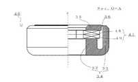
図1は、本発明の好ましい実施形態による(図示しない)動電型スピーカーを構成するスピーカー用磁気回路1を説明する図である。図1(a)は、スピーカー用磁気回路1の斜視図であり、図1(b)は、スピーカー用磁気回路1の側面図およびO−A断面図である。また、図2は、スピーカー用磁気回路1のマグネット組7を構成する第1マグネット8および第2マグネット9の配置を説明する断面平面図である。なお、説明に不要なスピーカー用磁気回路1および動電型スピーカーの一部の構造や、内部構造等は、図示並びに説明を省略する。 FIG. 1 is a diagram illustrating a speaker
本実施例のスピーカー用磁気回路1は、中心軸zに沿って設けられる貫通孔を含むセンターポール2を中央に配置するアンダープレート3を有するポール4と、その内径側端面とセンターポール2の側面との間に磁気空隙6を形成する略円環状のトッププレート5と、アンダープレート3およびトッププレート5の間に狭持されて同心円状に配置される10個のマグネット組7と、を備える外磁型磁気回路である。マグネット組7は、それぞれが、トッププレート5に連結する第1マグネット8と、アンダープレート3に連結する第2マグネット9と、を含む。第1マグネット8および第2マグネット9は、後述するように、同一寸法の略円筒形状を有する希土類磁石である。 The speaker
また、本実施例の(図示しない)動電型スピーカーは、図示するスピーカー用磁気回路1の他に、少なくとも、口径20cmの(図示しない)スピーカー振動板と、スピーカー振動板に連結する円筒形状の(図示しない)ボイスコイルボビンと、ボイスコイルボビンに巻回されて磁気空隙6に配置される(図示しない)ボイスコイルと、を備える。なお、動電型スピーカーは、スピーカー振動板を振動可能に支持し、スピーカー用磁気回路1に固定される略バスケット状の(図示しない)フレームと、ボイスコイルをフレームに対して振動可能に支持する(図示しない)ダンパーと、をさらに備えていても良い。 In addition to the speaker
ポール4およびトッププレート5は、軟鉄から構成されており、本実施例のポール4は、(図示しない)ボイスコイルボビンの可動振幅を確保するように、アンダープレート3に段部を設けている。ポール4のセンターポール2は、その直径が約50.0mmであり、トッププレート5は、約8.0mmの厚みを有する。したがって、スピーカー用磁気回路1は、トッププレート5の厚みに相当する広い範囲に渡って高い磁束密度を示す磁気空隙6を形成する。 The
それぞれのマグネット組7は、直径約24.0mmで厚み約6.0mmの略円筒形状を有する2つの希土類磁石が、積み上げられるように接着剤で連結されて構成されている。本実施例の動電型スピーカーでは、10組のマグネット組7が、ポール4のアンダープレート3の上に、等間隔で同心円状に配置されている。トッププレート5に連結する第1マグネット8と、アンダープレート3に連結する第2マグネット9は、小さい体積でも保磁力の強いNd−Fe−B系の希土類磁石である。なお、希土類磁石とは、Nd−Fe−B系のネオジウム磁石、もしくは、Sm−Co系のサマリウムコバルト磁石であって、磁石の最大エネルギー積(BH)maxが大きな値をとり、残留磁化および保磁力が大きい磁石である。希土類磁石は、保磁力が大きいので、高い磁束密度を発生させることができる一方で、パーミアンス係数が大きく、減磁しにくい。 Each magnet set 7 is configured by connecting two rare earth magnets having a substantially cylindrical shape with a diameter of about 24.0 mm and a thickness of about 6.0 mm, which are connected by an adhesive so as to be stacked. In the electrodynamic speaker of this embodiment, ten magnet sets 7 are concentrically arranged on the under
ここで、それぞれのマグネット組7では、同一の直径を有する第1マグネット8および第2マグネット9が、その中心位置をずらすようにして積み上げて連結されている。すなわち、図示するように、外磁型のスピーカー用磁気回路1のそれぞれのマグネット組7において、同心円状に配置される第1マグネット8が、第2マグネット9よりも磁気空隙6の近くになるように、中心点Oに近づいて配置される。図2に示すように、それぞれのマグネット組7は、同心円状に等間隔で配置される10個の第1マグネット8(実線)の内周端側位置を規定する第1半径r1が、同心円状に配置される10個の第2マグネット9(破線)の内周端側位置を規定する第2半径r2よりも小さくなるように構成されている。 Here, in each magnet set 7, the 1st magnet 8 and the
なお、本実施例の場合には、第1半径r1は約53.7mmであり、第2半径r2は約60.5mmであり、それぞれのマグネット組7では、第1マグネット8の中心位置が第2マグネット9の中心位置から約3.4mm中心点Oの方向にずれている。また、本実施例のトッププレート15の外径側端面の半径rtは約110.0mmであり、円筒形状の第1マグネット8の外周端側位置を規定する第3半径r3(=約101.7mm)よりも大きい。また、アンダープレート13の外径側端面の半径ruは約110.0mmであり、第2マグネット9の外周端側位置を規定する第4半径r4(=約108.5mm)よりも若干大きい。 In the case of the present embodiment, the first radius r1 is about 53.7 mm, the second radius r2 is about 60.5 mm, and in each magnet set 7, the center position of the first magnet 8 is the first position. 2 The center position of the
また、図2に示すように、スピーカー用磁気回路1のマグネット組7では、同心円状に隣り合う第1マグネット8同士の間隔を規定する距離w1が、隣り合う第2マグネット9同士の間隔を規定する距離w2よりも小さくなる。本実施例の場合には、隣接する第1マグネット8同士が接するまで近づくようにマグネット組7が配置されているので、距離w1は約0mmである。一方、第2マグネット9は、第1マグネット8と共通の円筒形状を有するので、第2マグネット9同士の間隔を規定する距離w2は大きくなり、約2.1mmである。 As shown in FIG. 2, in the magnet set 7 of the speaker
なお、それぞれのマグネット組7では、直径約24.0mmの第1マグネット8および第2マグネット9が、中心位置を約3.4mmずらすようにして積み上げて連結されている。このように、第1マグネット8および第2マグネット9が同一の直径を有する場合には、直径の約10%程度以上程度中心位置がずれていれば良い。中心点のずれが大きくなると第1マグネット8と第2マグネット9との連結が不安定になり、磁気空隙6での磁束密度が低下するおそれがあるので、直径の約25%程度以下の範囲で中心位置がずれていれば良い。 In each magnet set 7, a first magnet 8 and a
スピーカー振動板、ボイスコイルボビンおよびボイスコイルを含む(図示しない)スピーカー振動系は、動電型スピーカーのフレームに対して振動可能に支持される。したがって、動電型スピーカーでは、(図示しない)ターミナルおよび錦糸線を介してボイスコイルに音声電流が供給されると、磁気空隙6に配置されたボイスコイルに駆動力が作用し、ボイスコイルは前後方向に振動し、連結されたスピーカー振動板も前後方向に振動する。なお、動電型スピーカーにおいて前後とは、スピーカー振動板が振動する場合に、ボイスコイル、および、スピーカー用磁気回路1が取り付けられる側を後側とし、スピーカー振動板が露出する側を前側としている。大型のスピーカー用磁気回路1を含む本実施例の動電型スピーカーは、能率が高くて再生音圧レベルも高くすることができる。 A speaker vibration system (not shown) including a speaker diaphragm, a voice coil bobbin, and a voice coil is supported so as to be able to vibrate with respect to the frame of the electrodynamic speaker. Therefore, in an electrodynamic speaker, when a voice current is supplied to a voice coil via a terminal (not shown) and a tinsel wire, a driving force is applied to the voice coil disposed in the
図3は、本発明の好ましい実施形態による(図示しない)動電型スピーカーを構成する他の外磁型のスピーカー用磁気回路10を説明するO−A断面図である。本実施例のスピーカー用磁気回路10は、先の実施例のスピーカー用磁気回路1に代えて動電型スピーカーを構成するスピーカー用磁気回路であって、ポール14およびトッププレート15の形状寸法が異なる他は、磁気空隙6の寸法と、マグネット組7の構成が共通する磁気回路である。したがって、重複する構成、ならびに、説明に不要な構造、内部構造等は、図示並びに説明を省略する。 FIG. 3 is an OA cross-sectional view illustrating another external magnetic speaker
先の実施例の場合と同じ軟鉄から構成されているポール14およびトッププレート15は、センターポール12の直径と、トッププレート15の厚みとが、先の実施例の場合と共通する。一方で、トッププレート15の外径側端面の半径rtと、ポール14のアンダープレート13の外径側端面の半径ruとが、先の実施例の場合とは異なっている。具体的には、本実施例のトッププレート15の外径側端面の半径rtは約101.7mmであり、円筒形状の第1マグネット8の外周端側位置を規定する第3半径r3と等しい。また、アンダープレート13の外径側端面の半径ruは約108.5mmであり、第2マグネット9の外周端側位置を規定する第4半径r4と等しい。 The
図4は、本発明の好ましい実施形態によるスピーカー用磁気回路1、10、ならびに、後述する比較例の磁気回路20の磁気空隙6における磁束密度分布を表すグラフである。これらのスピーカー用磁気回路は、そのトッププレートが約8.0mmの厚みを有する大型の磁気回路であるので、実施例のスピーカー用磁気回路1、10の磁気空隙6では、トッププレートの厚みに相当する広い範囲に渡って、約1.6[T]以上の高い磁束密度を示している。また、先の実施例のスピーカー用磁気回路1に比較して、ポール14およびトッププレート15の寸法を変更した実施例のスピーカー用磁気回路10の方が、高い磁束密度を示す磁気空隙6を実現できている。したがって、本実施例のスピーカー用磁気回路10の方が、より能率が高くて再生音圧レベルも十分高い動電型スピーカーを実現することができる。 FIG. 4 is a graph showing the magnetic flux density distribution in the
図5は、比較例としての(図示しない)動電型スピーカーを構成する比較例の外磁型のスピーカー用磁気回路20を説明する図である。図5(a)は、スピーカー用磁気回路20の斜視図であり、図5(b)は、スピーカー用磁気回路20の側面図およびO−A断面図である。比較例のスピーカー用磁気回路20は、先の実施例のスピーカー用磁気回路1に代えて動電型スピーカーを構成できるスピーカー用磁気回路であって、それぞれのマグネット組27の構成が異なる他は、ポール4およびトッププレート5の形状寸法および磁気空隙6の寸法が共通する磁気回路である。したがって、重複する構成、ならびに、説明に不要な構造、内部構造等は、図示並びに説明を省略する。 FIG. 5 is a diagram for explaining an external magnetic speaker
それぞれのマグネット組27は、直径約24.0mmで厚み約6.0mmの略円筒形状を有する2つの希土類磁石が、ずれることなく積み上げられるように接着剤で連結されて構成されている。すなわち、マグネット組27は、単に同一寸法のマグネットを積み上げる場合であり、10組のマグネット組27は、ポール4のアンダープレート3の上に、半径約42.3mmの同心円上にその中心が位置するように等間隔で配置されている。トッププレート5に連結する第1マグネット28と、アンダープレート3に連結する第2マグネット29は、先の実施例と同じNd−Fe−B系の希土類磁石である。したがって、先の実施例を説明する図2を参考にしても分かるように、それぞれのマグネット組27は、同心円状に等間隔で配置される10個の第1マグネット28の内周端側位置を規定する第1半径r1が、同心円状に配置される10個の第2マグネット29の内周端側位置を規定する第2半径r2と等しくなる。 Each magnet set 27 is configured by connecting two rare earth magnets having a substantially cylindrical shape with a diameter of about 24.0 mm and a thickness of about 6.0 mm with an adhesive so that they can be stacked without deviation. That is, the magnet set 27 is simply a case where magnets having the same dimensions are stacked, and the 10 magnet sets 27 are positioned on the concentric circles having a radius of about 42.3 mm on the under
図4のグラフに示すように、比較例の磁気回路20の磁気空隙6における磁束密度分布は、先の実施例のスピーカー用磁気回路1、ならびに、10の場合に比べて低い値になり、約1.6[T]未満である。したがって、同心円状に配置される複数の円柱状のマグネットを使用することで、低コストで大型のスピーカー用磁気回路を実現する際に、複数のマグネットを多段に積み重ねる場合には、実施例のスピーカー用磁気回路1、ならびに、10のように、同心円状に配置される第1マグネット8が、第2マグネット9よりも磁気空隙6の近くになるように、マグネット組7を構成するのが好ましい。実施例の外磁型のスピーカー用磁気回路1、ならびに、10を用いる動電型スピーカーは、能率が高くて再生音圧レベルを高くでき、優れた再生音声品質を得ることができる。 As shown in the graph of FIG. 4, the magnetic flux density distribution in the
なお、本実施例のトッププレート15の外径側端面の半径rtは、円筒形状の第1マグネット8の外周端側位置を規定する第3半径r3と等しい場合であるが、半径rtは、第3半径r3以下であるのが好ましい。また、本実施例のポール14のアンダープレート13の外径側端面の半径ruは、第2マグネット9の外周端側位置を規定する第4半径r4と等しい場合であるが、半径ruは、以下であるのが好ましい。磁気空隙6における磁束密度を高めて、能率が高い動電型スピーカーを実現することができる。 In addition, the radius rt of the outer diameter side end surface of the top plate 15 of the present embodiment is the case where the radius rt is equal to the third radius r3 that defines the outer peripheral end side position of the cylindrical first magnet 8. It is preferable that the radius is 3 or less. Further, the radius ru of the outer diameter side end surface of the under plate 13 of the
なお、本実施例のマグネット組7は、トッププレート5に連結する第1マグネット8と、アンダープレート3に連結する第2マグネット9と、からなる2段の場合であるが、さらに第1マグネット8と第2マグネット9との間に配置されるマグネットを備えて、3段以上の複数段から構成されるものであっても良い。第1マグネット8の内周端側位置を規定する第1半径r1が、第2マグネット9を含む他のマグネットの内周端側位置を規定する半径の値よりも、小さくなればよい。第1マグネット8が磁気空隙6に近い位置になることで、磁気空隙6の磁束密度を高めることができる。 The magnet set 7 of this embodiment is a two-stage case including a first magnet 8 connected to the
また、センターポール2とアンダープレート3を一体に形成したポール4は、別々の部材をプレス加工、または、ネジ止め等により連結しても良い。また、ポール4は、実施例のような段付きのポールに限られるものではない。ポール4およびトッププレート5は、鉄を含む軟磁性の金属であればよく、電磁軟鉄、珪素鋼、電磁ステンレス、アモルファス、パーマロイ、パーメンジュールもしくはフェライトのいずれかから選択される軟磁性材料を使用しても良い。もちろん、第1マグネット8および第2マグネット9は、希土類磁石に限定されるものではなく、フェライト磁石であっても良い。 In addition, the
図6は、本発明の他の好ましい実施形態による(図示しない)動電型スピーカーを構成するスピーカー用磁気回路30を説明する図である。図6は、スピーカー用磁気回路30の一部を断面図にした斜視図であり、先の実施例1の図1(b)と同様のO−A断面図を含む。また、図2は、スピーカー用磁気回路30のマグネット組37を構成する第1マグネット38および第2マグネット39の配置を説明する断面平面図である。なお、説明に不要なスピーカー用磁気回路30および動電型スピーカーの一部の構造や、内部構造等は、図示並びに説明を省略する。 FIG. 6 is a diagram illustrating a speaker
本実施例のスピーカー用磁気回路30は、中心軸zに沿って設けられる貫通孔を含むセンターポール32を中央に配置する円筒壁部33を有するヨーク34と、 その外径側端面とヨーク34の円筒壁部33の内側面との間に磁気空隙36を形成する略円環状のトップポール35と、センターポール32およびトップポール35の間に狭持されて同心円状に配置される8個のマグネット組37と、を備える内磁型磁気回路である。それぞれのマグネット組37は、トップポール35に連結する第1マグネット38と、ヨーク34のセンターポール32に連結する第2マグネット39と、を含む。第1マグネット38および第2マグネット39は、同一寸法の略円筒形状を有する希土類磁石である。 The speaker
また、本実施例の(図示しない)動電型スピーカーは、図示するスピーカー用磁気回路30の他に、少なくとも、口径30cmの(図示しない)スピーカー振動板と、スピーカー振動板に連結する円筒形状の(図示しない)ボイスコイルボビンと、ボイスコイルボビンに巻回されて磁気空隙36に配置される(図示しない)ボイスコイルと、を備える。なお、動電型スピーカーは、スピーカー振動板を振動可能に支持し、スピーカー用磁気回路30に固定される略バスケット状の(図示しない)フレームと、ボイスコイルをフレームに対して振動可能に支持する(図示しない)ダンパーと、をさらに備えていても良い。 In addition to the speaker
ヨーク34およびトップポール35は、軟鉄から構成されており、本実施例のヨーク34は、センターポール32と円筒壁部33との間に(図示しない)ボイスコイルボビンの可動振幅を確保する段部を設けている。トップポール35の直径は約99.1mmであり、トップポール35の厚みは約8.0mmである。したがって、スピーカー用磁気回路30は、トップポール35の厚みに相当する広い範囲に渡って高い磁束密度を示す磁気空隙36を形成する。 The
それぞれのマグネット組37は、直径約24.0mmで厚み約6.0mmの略円筒形状を有する2つの希土類磁石が、積み上げられるように接着剤で連結されて構成されている。本実施例の動電型スピーカーでは、8組のマグネット組37が、ヨーク34のセンターポール32の上に、等間隔で同心円状に配置されている。トップポール35に連結する第1マグネット38と、ヨーク34のセンターポール32に連結する第2マグネット39は、小さい体積でも保磁力の強いNd−Fe−B系の希土類磁石である。 Each magnet set 37 is configured by connecting two rare earth magnets having a substantially cylindrical shape with a diameter of about 24.0 mm and a thickness of about 6.0 mm, which are connected with an adhesive so as to be stacked. In the electrodynamic speaker of this embodiment, eight magnet sets 37 are arranged concentrically on the
ここで、それぞれのマグネット組37では、同一の直径を有する第1マグネット38および第2マグネット39が、その中心位置をずらすようにして積み上げて連結されている。すなわち、図示するように、内磁型のスピーカー用磁気回路30のそれぞれのマグネット組37において、同心円状に配置される第1マグネット38が、第2マグネット39よりも磁気空隙36の近くになるように、中心点Oから遠ざかる方向へ配置される。図7に示すように、それぞれのマグネット組7は、同心円状に等間隔で配置される8個の第1マグネット38(破線)の外周端側位置を規定する第1半径R1が、同心円状に配置される8個の第2マグネット39(破線)の外周端側位置を規定する第2半径R2よりも大きくなるように構成されている。 Here, in each magnet set 37, the
なお、本実施例の場合には、第1半径R1は約49.0mmであり、第2半径R2は約47.0mmであり、それぞれのマグネット組37では、第1マグネット38の中心位置が第2マグネット39の中心位置から約2.0mm中心点Oとは反対方向にずれている。また、図7に示すように、スピーカー用磁気回路30のマグネット組37では、同心円状に隣り合う第1マグネット38同士の間隔を規定する距離w1が、隣り合う第2マグネット39同士の間隔を規定する距離w2よりも大きくなる。本実施例の場合には、隣接する第1マグネット38同士の距離w1は約4.74mmであり、一方、第2マグネット39同士の間隔を規定する距離w2は小さくなり、約4.32mmである。 In the present embodiment, the first radius R1 is about 49.0 mm, the second radius R2 is about 47.0 mm, and the center position of the
スピーカー振動板、ボイスコイルボビンおよびボイスコイルを含む(図示しない)スピーカー振動系は、動電型スピーカーのフレームに対して振動可能に支持される。したがって、動電型スピーカーでは、(図示しない)ターミナルおよび錦糸線を介してボイスコイルに音声電流が供給されると、磁気空隙36に配置されたボイスコイルに駆動力が作用し、ボイスコイルは前後方向に振動し、連結されたスピーカー振動板も前後方向に振動する。なお、動電型スピーカーにおいて前後とは、スピーカー振動板が振動する場合に、ボイスコイル、および、スピーカー用磁気回路30が取り付けられる側を後側とし、スピーカー振動板が露出する側を前側としている。大型のスピーカー用磁気回路30を含む本実施例の動電型スピーカーは、能率が高くて再生音圧レベルも高くすることができる。 A speaker vibration system (not shown) including a speaker diaphragm, a voice coil bobbin, and a voice coil is supported so as to be able to vibrate with respect to the frame of the electrodynamic speaker. Therefore, in an electrodynamic speaker, when a voice current is supplied to a voice coil via a terminal (not shown) and a tinsel wire, a driving force is applied to the voice coil arranged in the
図8は、本発明の好ましい実施形態によるスピーカー用磁気回路30、ならびに、後述する比較例の磁気回路40の磁気空隙36における磁束密度分布を表すグラフである。これらのスピーカー用磁気回路は、そのトッププレートが約8.0mmの厚みを有する大型の磁気回路であるので、実施例のスピーカー用磁気回路30の磁気空隙36では、トップポール35の厚みに相当する広い範囲に渡って、約0.88[T]以上の高い磁束密度を示している。したがって、本実施例のスピーカー用磁気回路30の方が、比較例の磁気回路40の場合よりも能率が高くて再生音圧レベルも十分高い動電型スピーカーを実現することができる。 FIG. 8 is a graph showing the magnetic flux density distribution in the
図9は、比較例としての(図示しない)動電型スピーカーを構成する比較例の内磁型のスピーカー用磁気回路40を説明する図であり、その右半分がスピーカー用磁気回路40のO−A断面図である。比較例のスピーカー用磁気回路40は、先の実施例のスピーカー用磁気回路30に代えて動電型スピーカーを構成できるスピーカー用磁気回路であって、それぞれのマグネット組47の構成が異なる他は、ヨーク34およびトップポール35の形状寸法および磁気空隙36の寸法が共通する磁気回路である。したがって、重複する構成、ならびに、説明に不要な構造、内部構造等は、図示並びに説明を省略する。 FIG. 9 is a diagram for explaining an internal magnet type speaker
それぞれのマグネット組47は、直径約24.0mmで厚み約6.0mmの略円筒形状を有する2つの希土類磁石が、ずれることなく積み上げられるように接着剤で連結されて構成されている。すなわち、マグネット組47は、単に同一寸法のマグネットを積み上げる場合であり、8組のマグネット組47は、ヨーク34のセンターポール32の上に、半径約35.0mmの同心円上にその中心が位置するように等間隔で配置されている。トップポール35に連結する第1マグネット48と、ヨーク34に連結する第2マグネット39は、先の実施例と同じNd−Fe−B系の希土類磁石である。したがって、先の実施例を説明する図7を参考にしても分かるように、それぞれのマグネット組47は、同心円状に等間隔で配置される8個の第1マグネット48の内周端側位置を規定する第1半径R1が、同心円状に配置される8個の第2マグネット49の内周端側位置を規定する第2半径R2と等しくなる。 Each magnet set 47 is configured by connecting two rare earth magnets having a substantially cylindrical shape with a diameter of about 24.0 mm and a thickness of about 6.0 mm with an adhesive so as to be stacked without deviation. That is, the magnet set 47 is a case where magnets of the same size are simply stacked, and the eight magnet sets 47 are located on the
図8のグラフに示すように、比較例の磁気回路40の磁気空隙36における磁束密度分布は、先の実施例のスピーカー用磁気回路30の場合に比べて低い値になり、約0.86[T]程度である。したがって、同心円状に配置される複数の円柱状のマグネットを使用することで、低コストで大型のスピーカー用磁気回路を実現する際に、複数のマグネットを多段に積み重ねる場合には、実施例のスピーカー用磁気回路30のように、同心円状に配置される第1マグネット38が、第2マグネット39よりも磁気空隙36の近くになるように、マグネット組37を構成するのが好ましい。実施例の内磁型のスピーカー用磁気回30を用いる動電型スピーカーは、能率が高くて再生音圧レベルを高くでき、優れた再生音声品質を得ることができる。 As shown in the graph of FIG. 8, the magnetic flux density distribution in the
本発明の動電型スピーカーは、大型の磁気回路を備えるスピーカーに限られず、小型であっても複数のマグネットを使用する磁気回路を備える動電型スピーカー、ヘッドフォン、マイクロホン等の他の電機−機械−音響変換器にも適用が可能である。 The electrodynamic speaker of the present invention is not limited to a speaker having a large magnetic circuit, and other electro-mechanical machines such as an electrodynamic speaker, a headphone, and a microphone having a magnetic circuit using a plurality of magnets even if they are small. -Applicable to acoustic transducers.
1、10、20 スピーカー用磁気回路
2、12 センターポール
3、13 アンダープレート
4、14 ポール
5、15 トッププレート
6 磁気空隙
7、27 マグネット組
8、28 第1マグネット
9、29 第2マグネット
30、40 スピーカー用磁気回路
32 センターポール
33 円筒筒部
34 ヨーク
35 トップポール
36 磁気空隙
37、47 マグネット組
38、48 第1マグネット
39、49 第2マグネット
1, 10, 20 Speaker
Claims (6)
Translated fromJapaneseその内径側端面と該センターポールの側面との間に磁気空隙を形成する略円環状のトッププレートと、
該アンダープレートおよび該トッププレートの間に狭持されて同心円状に配置される複数のマグネット組と、を備え、
該複数のマグネット組のそれぞれが、該トッププレートに連結する第1マグネットと、該アンダープレートに連結する第2マグネットと、を含み、
同心円状に配置される複数の該第1マグネットの内周端側位置を規定する第1半径r1が、同心円状に配置される複数の該第2マグネットの内周端側位置を規定する第2半径r2よりも小さくなるように、それぞれの該マグネット組が構成されている、スピーカー用磁気回路。A pole having an under plate for placing the center pole in the center;
A substantially annular top plate forming a magnetic air gap between the inner diameter side end surface and the side surface of the center pole;
A plurality of magnet sets sandwiched between the under plate and the top plate and arranged concentrically,
Each of the plurality of magnet sets includes a first magnet coupled to the top plate and a second magnet coupled to the under plate.
A first radius r1 that defines the inner peripheral end side positions of the plurality of first magnets arranged concentrically is a second radius that defines the inner peripheral end side positions of the plurality of second magnets arranged concentrically. A speaker magnetic circuit in which each of the magnet sets is configured to be smaller than the radius r2.
その外径側端面と該ヨークの該円筒壁部の内側面との間に磁気空隙を形成する略円環状のトップポールと、
該センターポールおよび該トップポールの間に狭持されて同心円状に配置される複数のマグネット組と、を備え、
該複数のマグネット組のそれぞれが、該トップポールに連結する第1マグネットと、該ヨークの該センターポールに連結する第2マグネットと、を含み、
同心円状に配置される複数の該第1マグネットの外周端側位置を規定する第1半径R1が、同心円状に配置される複数の該第2マグネットの外周端側位置を規定する第2半径R2よりも大きくなるように、それぞれの該マグネット組が構成されている、スピーカー用磁気回路。A yoke having a cylindrical wall portion in which the center pole is arranged in the center;
A substantially annular top pole that forms a magnetic gap between the outer diameter side end surface and the inner side surface of the cylindrical wall of the yoke;
A plurality of magnet sets sandwiched between the center pole and the top pole and arranged concentrically,
Each of the plurality of magnet sets includes a first magnet coupled to the top pole and a second magnet coupled to the center pole of the yoke;
A first radius R1 that defines the outer peripheral end positions of the plurality of first magnets arranged concentrically is a second radius R2 that defines the outer peripheral end positions of the plurality of second magnets arranged concentrically. A magnetic circuit for a speaker, wherein each of the magnet sets is configured to be larger than the speaker.
請求項1または2に記載のスピーカー用磁気回路。The first magnet and the second magnet are rare earth magnets having a substantially cylindrical shape with the same dimensions,
The speaker magnetic circuit according to claim 1 or 2.
請求項3に記載のスピーカー用磁気回路。Each of the magnet sets is configured such that a distance w1 that defines the interval between the first magnets that are concentrically adjacent to each other is different from a distance w2 that defines the interval between the adjacent second magnets.
The magnetic circuit for a speaker according to claim 3.
請求項1または3に記載のスピーカー用磁気回路。A radius rt of the outer diameter side end surface of the top plate is equal to or less than a third radius r3 that defines a position of the outer peripheral end side of the first magnet, and a radius ru of the outer diameter side end surface of the under plate is equal to the second magnet. Is a fourth radius r4 or less that defines the outer peripheral end side position of
The magnetic circuit for a speaker according to claim 1 or 3.
スピーカー振動板と、
該スピーカー振動板に連結する円筒形状のボイスコイルボビンと、
該ボイスコイルボビンに巻回されて該磁気空隙に配置されるボイスコイルと、
を備える、動電型スピーカー。The speaker magnetic circuit according to any one of claims 1 to 5,
A speaker diaphragm,
A cylindrical voice coil bobbin connected to the speaker diaphragm;
A voice coil wound around the voice coil bobbin and disposed in the magnetic gap;
An electrodynamic type speaker.
Priority Applications (1)
| Application Number | Priority Date | Filing Date | Title |
|---|---|---|---|
| JP2009290434AJP2010246087A (en) | 2009-03-19 | 2009-12-22 | Magnetic circuit for speaker and electrodynamic speaker using the same |
Applications Claiming Priority (2)
| Application Number | Priority Date | Filing Date | Title |
|---|---|---|---|
| JP2009068565 | 2009-03-19 | ||
| JP2009290434AJP2010246087A (en) | 2009-03-19 | 2009-12-22 | Magnetic circuit for speaker and electrodynamic speaker using the same |
Publications (1)
| Publication Number | Publication Date |
|---|---|
| JP2010246087Atrue JP2010246087A (en) | 2010-10-28 |
Family
ID=43098565
Family Applications (1)
| Application Number | Title | Priority Date | Filing Date |
|---|---|---|---|
| JP2009290434APendingJP2010246087A (en) | 2009-03-19 | 2009-12-22 | Magnetic circuit for speaker and electrodynamic speaker using the same |
Country Status (1)
| Country | Link |
|---|---|
| JP (1) | JP2010246087A (en) |
Cited By (4)
| Publication number | Priority date | Publication date | Assignee | Title |
|---|---|---|---|---|
| KR101722530B1 (en)* | 2016-03-25 | 2017-04-03 | 에스텍 주식회사 | speaker |
| CN109937582A (en)* | 2016-09-22 | 2019-06-25 | 迈特公司 | Loudspeaker unit with multiple driving units |
| CN115348511A (en)* | 2022-08-11 | 2022-11-15 | 青岛海信激光显示股份有限公司 | Drivers and speaker components |
| US12028698B2 (en) | 2021-04-08 | 2024-07-02 | Samsung Electronics Co., Ltd. | Air purifier and method for outputting sound by air purifier |
- 2009
- 2009-12-22JPJP2009290434Apatent/JP2010246087A/enactivePending
Cited By (9)
| Publication number | Priority date | Publication date | Assignee | Title |
|---|---|---|---|---|
| KR101722530B1 (en)* | 2016-03-25 | 2017-04-03 | 에스텍 주식회사 | speaker |
| CN109937582A (en)* | 2016-09-22 | 2019-06-25 | 迈特公司 | Loudspeaker unit with multiple driving units |
| JP2019530353A (en)* | 2016-09-22 | 2019-10-17 | メイト ビー.ブイ.Mayht B.V. | Loudspeaker unit with multiple drive units |
| US20200037078A1 (en)* | 2016-09-22 | 2020-01-30 | Mayht B.V. | Loudspeaker unit with multiple drive units |
| US10893367B2 (en)* | 2016-09-22 | 2021-01-12 | Mayht Holding B.V. | Loudspeaker unit with multiple drive units |
| CN109937582B (en)* | 2016-09-22 | 2021-07-09 | 迈特公司 | Loudspeaker unit with multiple drive units |
| JP7074408B2 (en) | 2016-09-22 | 2022-05-24 | メイト ホールディング ビー.ブイ. | Loudspeaker unit with multiple drive units |
| US12028698B2 (en) | 2021-04-08 | 2024-07-02 | Samsung Electronics Co., Ltd. | Air purifier and method for outputting sound by air purifier |
| CN115348511A (en)* | 2022-08-11 | 2022-11-15 | 青岛海信激光显示股份有限公司 | Drivers and speaker components |
Similar Documents
| Publication | Publication Date | Title |
|---|---|---|
| US7317810B2 (en) | Magnetic circuit and speaker | |
| CN1943272B (en) | Electrokinetic electro-acoustic converter and electronic device | |
| US7020301B2 (en) | Loudspeaker | |
| EP1257148A2 (en) | Loudspeaker for a portable communication device | |
| KR102706153B1 (en) | High-resolution electro-magnetic speaker of bridge edge method | |
| CN101911720A (en) | Multi-magnet loudspeaker | |
| WO2007135745A1 (en) | Speaker device | |
| JP2008312056A (en) | Electroacoustic transducer | |
| JP4878625B2 (en) | Speaker device | |
| CN112533112B (en) | Double-magnetic circuit structure and sound production device | |
| JP2010246087A (en) | Magnetic circuit for speaker and electrodynamic speaker using the same | |
| CN101175340A (en) | Electroacoustic transducer | |
| CN110169084A (en) | Ultra-thin high-resolution electromagnetic speaker with bridge-shaped edge method | |
| JP2009094914A (en) | Speaker | |
| JP2009267779A (en) | Electromagnetic electro-acoustic transducer | |
| JP2023540061A (en) | flat speaker driven by a single permanent magnet and one or more voice coils | |
| JP4385981B2 (en) | Electrodynamic speaker | |
| JPH11187484A (en) | Loudspeaker | |
| WO2016051744A1 (en) | Magnetic circuit and loudspeaker using same | |
| JP2009094912A (en) | Speaker | |
| JP3888146B2 (en) | Speaker | |
| JP4952930B2 (en) | Electrodynamic speaker | |
| JP2013255087A (en) | Magnetic circuit and electrodynamic speaker employing the same | |
| JP2009171475A (en) | Ring type speaker and manufacturing method thereof | |
| JP2009094915A (en) | Speaker |
Legal Events
| Date | Code | Title | Description |
|---|---|---|---|
| A711 | Notification of change in applicant | Free format text:JAPANESE INTERMEDIATE CODE: A712 Effective date:20101227 |