JP2010245448A - Film depositing device, film depositing method, and storage medium - Google Patents
Film depositing device, film depositing method, and storage mediumDownload PDFInfo
- Publication number
- JP2010245448A JP2010245448AJP2009095210AJP2009095210AJP2010245448AJP 2010245448 AJP2010245448 AJP 2010245448AJP 2009095210 AJP2009095210 AJP 2009095210AJP 2009095210 AJP2009095210 AJP 2009095210AJP 2010245448 AJP2010245448 AJP 2010245448A
- Authority
- JP
- Japan
- Prior art keywords
- gas
- substrate
- reaction
- reaction gas
- gas supply
- Prior art date
- Legal status (The legal status is an assumption and is not a legal conclusion. Google has not performed a legal analysis and makes no representation as to the accuracy of the status listed.)
- Granted
Links
- 238000000034methodMethods0.000titleclaimsdescription60
- 238000003860storageMethods0.000titleclaimsdescription9
- 238000000151depositionMethods0.000titleabstractdescription4
- 239000007789gasSubstances0.000claimsabstractdescription458
- 239000010408filmSubstances0.000claimsabstractdescription138
- 239000000758substrateSubstances0.000claimsabstractdescription122
- 238000010438heat treatmentMethods0.000claimsabstractdescription79
- 239000007795chemical reaction productSubstances0.000claimsabstractdescription56
- 239000013067intermediate productSubstances0.000claimsabstractdescription31
- 239000010409thin filmSubstances0.000claimsabstractdescription19
- 239000012495reaction gasSubstances0.000claimsdescription174
- 238000000926separation methodMethods0.000claimsdescription113
- 238000012545processingMethods0.000claimsdescription88
- 238000006243chemical reactionMethods0.000claimsdescription28
- 230000008569processEffects0.000claimsdescription21
- 238000011144upstream manufacturingMethods0.000claimsdescription19
- OAICVXFJPJFONN-UHFFFAOYSA-NPhosphorusChemical compound[P]OAICVXFJPJFONN-UHFFFAOYSA-N0.000claimsdescription10
- 229910052698phosphorusInorganic materials0.000claimsdescription10
- 239000011574phosphorusSubstances0.000claimsdescription10
- ZOXJGFHDIHLPTG-UHFFFAOYSA-NBoronChemical compound[B]ZOXJGFHDIHLPTG-UHFFFAOYSA-N0.000claimsdescription8
- 229910052796boronInorganic materials0.000claimsdescription8
- 230000007246mechanismEffects0.000claimsdescription8
- 238000005192partitionMethods0.000claimsdescription8
- 238000010030laminatingMethods0.000claimsdescription7
- 230000015572biosynthetic processEffects0.000claimsdescription6
- 238000000280densificationMethods0.000claimsdescription5
- 238000001179sorption measurementMethods0.000claimsdescription5
- 238000004590computer programMethods0.000claimsdescription4
- 239000012530fluidSubstances0.000claimsdescription3
- 239000000047productSubstances0.000claimsdescription3
- 238000000638solvent extractionMethods0.000claimsdescription2
- 239000000376reactantSubstances0.000abstract5
- 235000012431wafersNutrition0.000description123
- LFQSCWFLJHTTHZ-UHFFFAOYSA-NEthanolChemical compoundCCOLFQSCWFLJHTTHZ-UHFFFAOYSA-N0.000description62
- VYPSYNLAJGMNEJ-UHFFFAOYSA-NSilicium dioxideChemical compoundO=[Si]=OVYPSYNLAJGMNEJ-UHFFFAOYSA-N0.000description51
- 229910052814silicon oxideInorganic materials0.000description44
- 235000019441ethanolNutrition0.000description33
- 230000002093peripheral effectEffects0.000description28
- 238000009792diffusion processMethods0.000description25
- 238000010926purgeMethods0.000description23
- 238000012546transferMethods0.000description21
- 238000000231atomic layer depositionMethods0.000description13
- KPUWHANPEXNPJT-UHFFFAOYSA-NdisiloxaneChemical class[SiH3]O[SiH3]KPUWHANPEXNPJT-UHFFFAOYSA-N0.000description12
- 239000012535impuritySubstances0.000description12
- 239000010410layerSubstances0.000description12
- 229920000642polymerPolymers0.000description12
- 230000004913activationEffects0.000description8
- 238000007599dischargingMethods0.000description7
- 239000002052molecular layerSubstances0.000description7
- XLYOFNOQVPJJNP-UHFFFAOYSA-NwaterChemical compoundOXLYOFNOQVPJJNP-UHFFFAOYSA-N0.000description7
- 238000010586diagramMethods0.000description6
- 230000000694effectsEffects0.000description6
- 235000012239silicon dioxideNutrition0.000description5
- XKRFYHLGVUSROY-UHFFFAOYSA-NArgonChemical compound[Ar]XKRFYHLGVUSROY-UHFFFAOYSA-N0.000description4
- OKKJLVBELUTLKV-UHFFFAOYSA-NMethanolChemical compoundOCOKKJLVBELUTLKV-UHFFFAOYSA-N0.000description4
- 230000009471actionEffects0.000description4
- 238000000137annealingMethods0.000description4
- QVGXLLKOCUKJST-UHFFFAOYSA-Natomic oxygenChemical compound[O]QVGXLLKOCUKJST-UHFFFAOYSA-N0.000description4
- 238000002156mixingMethods0.000description4
- 230000003647oxidationEffects0.000description4
- 238000007254oxidation reactionMethods0.000description4
- 239000000126substanceSubstances0.000description4
- IJGRMHOSHXDMSA-UHFFFAOYSA-NAtomic nitrogenChemical compoundN#NIJGRMHOSHXDMSA-UHFFFAOYSA-N0.000description3
- XUIMIQQOPSSXEZ-UHFFFAOYSA-NSiliconChemical compound[Si]XUIMIQQOPSSXEZ-UHFFFAOYSA-N0.000description3
- 238000013459approachMethods0.000description3
- 238000005229chemical vapour depositionMethods0.000description3
- 229910052681coesiteInorganic materials0.000description3
- 150000001875compoundsChemical class0.000description3
- 229910052906cristobaliteInorganic materials0.000description3
- QOSATHPSBFQAML-UHFFFAOYSA-Nhydrogen peroxide;hydrateChemical compoundO.OOQOSATHPSBFQAML-UHFFFAOYSA-N0.000description3
- 125000002887hydroxy groupChemical group[H]O*0.000description3
- 238000002955isolationMethods0.000description3
- 239000000203mixtureSubstances0.000description3
- 239000001301oxygenSubstances0.000description3
- 229910052760oxygenInorganic materials0.000description3
- 238000007789sealingMethods0.000description3
- 239000010703siliconSubstances0.000description3
- 229910052710siliconInorganic materials0.000description3
- 239000000377silicon dioxideSubstances0.000description3
- -1silicon nitride compoundChemical class0.000description3
- 229910052682stishoviteInorganic materials0.000description3
- 229910052905tridymiteInorganic materials0.000description3
- OKTJSMMVPCPJKN-UHFFFAOYSA-NCarbonChemical compound[C]OKTJSMMVPCPJKN-UHFFFAOYSA-N0.000description2
- CBENFWSGALASAD-UHFFFAOYSA-NOzoneChemical compound[O-][O+]=OCBENFWSGALASAD-UHFFFAOYSA-N0.000description2
- XYFCBTPGUUZFHI-UHFFFAOYSA-NPhosphineChemical compoundPXYFCBTPGUUZFHI-UHFFFAOYSA-N0.000description2
- 229910020175SiOHInorganic materials0.000description2
- 230000002411adverseEffects0.000description2
- 229910052786argonInorganic materials0.000description2
- 238000007664blowingMethods0.000description2
- 229910052799carbonInorganic materials0.000description2
- 229910001873dinitrogenInorganic materials0.000description2
- 238000011049fillingMethods0.000description2
- 239000001257hydrogenSubstances0.000description2
- 229910052739hydrogenInorganic materials0.000description2
- 125000004435hydrogen atomChemical class[H]*0.000description2
- 239000011261inert gasSubstances0.000description2
- 238000004519manufacturing processMethods0.000description2
- 239000002245particleSubstances0.000description2
- 238000000206photolithographyMethods0.000description2
- 230000002265preventionEffects0.000description2
- 239000010453quartzSubstances0.000description2
- 239000004065semiconductorSubstances0.000description2
- SCPYDCQAZCOKTP-UHFFFAOYSA-NsilanolChemical compound[SiH3]OSCPYDCQAZCOKTP-UHFFFAOYSA-N0.000description2
- 239000002344surface layerSubstances0.000description2
- 239000010936titaniumSubstances0.000description2
- WXRGABKACDFXMG-UHFFFAOYSA-NtrimethylboraneChemical compoundCB(C)CWXRGABKACDFXMG-UHFFFAOYSA-N0.000description2
- CGRVKSPUKAFTBN-UHFFFAOYSA-NN-silylbutan-1-amineChemical compoundCCCCN[SiH3]CGRVKSPUKAFTBN-UHFFFAOYSA-N0.000description1
- 229910052581Si3N4Inorganic materials0.000description1
- SEQDDYPDSLOBDC-UHFFFAOYSA-NTemazepamChemical compoundN=1C(O)C(=O)N(C)C2=CC=C(Cl)C=C2C=1C1=CC=CC=C1SEQDDYPDSLOBDC-UHFFFAOYSA-N0.000description1
- PPWHTZKZQNXVAE-UHFFFAOYSA-NTetracaine hydrochlorideChemical compoundCl.CCCCNC1=CC=C(C(=O)OCCN(C)C)C=C1PPWHTZKZQNXVAE-UHFFFAOYSA-N0.000description1
- RTAQQCXQSZGOHL-UHFFFAOYSA-NTitaniumChemical compound[Ti]RTAQQCXQSZGOHL-UHFFFAOYSA-N0.000description1
- KJNGJIPPQOFCSK-UHFFFAOYSA-N[H][Sr][H]Chemical compound[H][Sr][H]KJNGJIPPQOFCSK-UHFFFAOYSA-N0.000description1
- 150000001298alcoholsChemical class0.000description1
- 125000000217alkyl groupChemical group0.000description1
- 230000005540biological transmissionEffects0.000description1
- OYACROKNLOSFPA-UHFFFAOYSA-Ncalcium;dioxido(oxo)silaneChemical compound[Ca+2].[O-][Si]([O-])=OOYACROKNLOSFPA-UHFFFAOYSA-N0.000description1
- 239000000919ceramicSubstances0.000description1
- 230000008021depositionEffects0.000description1
- 230000000994depressogenic effectEffects0.000description1
- 238000001514detection methodMethods0.000description1
- MROCJMGDEKINLD-UHFFFAOYSA-NdichlorosilaneChemical compoundCl[SiH2]ClMROCJMGDEKINLD-UHFFFAOYSA-N0.000description1
- 239000003989dielectric materialSubstances0.000description1
- 230000003028elevating effectEffects0.000description1
- 238000002474experimental methodMethods0.000description1
- 238000005243fluidizationMethods0.000description1
- 230000006870functionEffects0.000description1
- 230000009477glass transitionEffects0.000description1
- 230000005484gravityEffects0.000description1
- 238000011068loading methodMethods0.000description1
- 238000005259measurementMethods0.000description1
- VNWKTOKETHGBQD-UHFFFAOYSA-NmethaneNatural productsCVNWKTOKETHGBQD-UHFFFAOYSA-N0.000description1
- 239000005416organic matterSubstances0.000description1
- 230000000149penetrating effectEffects0.000description1
- 229910000073phosphorus hydrideInorganic materials0.000description1
- 239000002994raw materialSubstances0.000description1
- FZHAPNGMFPVSLP-UHFFFAOYSA-NsilanamineChemical compound[SiH3]NFZHAPNGMFPVSLP-UHFFFAOYSA-N0.000description1
- 239000007787solidSubstances0.000description1
- 229910052712strontiumInorganic materials0.000description1
- YBRBMKDOPFTVDT-UHFFFAOYSA-Ntert-butylamineChemical compoundCC(C)(C)NYBRBMKDOPFTVDT-UHFFFAOYSA-N0.000description1
- 229910052719titaniumInorganic materials0.000description1
- LXEXBJXDGVGRAR-UHFFFAOYSA-Ntrichloro(trichlorosilyl)silaneChemical compoundCl[Si](Cl)(Cl)[Si](Cl)(Cl)ClLXEXBJXDGVGRAR-UHFFFAOYSA-N0.000description1
- JLTRXTDYQLMHGR-UHFFFAOYSA-NtrimethylaluminiumChemical compoundC[Al](C)CJLTRXTDYQLMHGR-UHFFFAOYSA-N0.000description1
Images


Classifications
- H—ELECTRICITY
- H01—ELECTRIC ELEMENTS
- H01L—SEMICONDUCTOR DEVICES NOT COVERED BY CLASS H10
- H01L21/00—Processes or apparatus adapted for the manufacture or treatment of semiconductor or solid state devices or of parts thereof
- H01L21/67—Apparatus specially adapted for handling semiconductor or electric solid state devices during manufacture or treatment thereof; Apparatus specially adapted for handling wafers during manufacture or treatment of semiconductor or electric solid state devices or components ; Apparatus not specifically provided for elsewhere
- H01L21/67005—Apparatus not specifically provided for elsewhere
- H01L21/67011—Apparatus for manufacture or treatment
- H01L21/67098—Apparatus for thermal treatment
- H01L21/67115—Apparatus for thermal treatment mainly by radiation
- C—CHEMISTRY; METALLURGY
- C23—COATING METALLIC MATERIAL; COATING MATERIAL WITH METALLIC MATERIAL; CHEMICAL SURFACE TREATMENT; DIFFUSION TREATMENT OF METALLIC MATERIAL; COATING BY VACUUM EVAPORATION, BY SPUTTERING, BY ION IMPLANTATION OR BY CHEMICAL VAPOUR DEPOSITION, IN GENERAL; INHIBITING CORROSION OF METALLIC MATERIAL OR INCRUSTATION IN GENERAL
- C23C—COATING METALLIC MATERIAL; COATING MATERIAL WITH METALLIC MATERIAL; SURFACE TREATMENT OF METALLIC MATERIAL BY DIFFUSION INTO THE SURFACE, BY CHEMICAL CONVERSION OR SUBSTITUTION; COATING BY VACUUM EVAPORATION, BY SPUTTERING, BY ION IMPLANTATION OR BY CHEMICAL VAPOUR DEPOSITION, IN GENERAL
- C23C16/00—Chemical coating by decomposition of gaseous compounds, without leaving reaction products of surface material in the coating, i.e. chemical vapour deposition [CVD] processes
- C23C16/44—Chemical coating by decomposition of gaseous compounds, without leaving reaction products of surface material in the coating, i.e. chemical vapour deposition [CVD] processes characterised by the method of coating
- C23C16/455—Chemical coating by decomposition of gaseous compounds, without leaving reaction products of surface material in the coating, i.e. chemical vapour deposition [CVD] processes characterised by the method of coating characterised by the method used for introducing gases into reaction chamber or for modifying gas flows in reaction chamber
- C23C16/45523—Pulsed gas flow or change of composition over time
- C23C16/45525—Atomic layer deposition [ALD]
- C23C16/45544—Atomic layer deposition [ALD] characterized by the apparatus
- C23C16/45548—Atomic layer deposition [ALD] characterized by the apparatus having arrangements for gas injection at different locations of the reactor for each ALD half-reaction
- C23C16/45551—Atomic layer deposition [ALD] characterized by the apparatus having arrangements for gas injection at different locations of the reactor for each ALD half-reaction for relative movement of the substrate and the gas injectors or half-reaction reactor compartments
- C—CHEMISTRY; METALLURGY
- C23—COATING METALLIC MATERIAL; COATING MATERIAL WITH METALLIC MATERIAL; CHEMICAL SURFACE TREATMENT; DIFFUSION TREATMENT OF METALLIC MATERIAL; COATING BY VACUUM EVAPORATION, BY SPUTTERING, BY ION IMPLANTATION OR BY CHEMICAL VAPOUR DEPOSITION, IN GENERAL; INHIBITING CORROSION OF METALLIC MATERIAL OR INCRUSTATION IN GENERAL
- C23C—COATING METALLIC MATERIAL; COATING MATERIAL WITH METALLIC MATERIAL; SURFACE TREATMENT OF METALLIC MATERIAL BY DIFFUSION INTO THE SURFACE, BY CHEMICAL CONVERSION OR SUBSTITUTION; COATING BY VACUUM EVAPORATION, BY SPUTTERING, BY ION IMPLANTATION OR BY CHEMICAL VAPOUR DEPOSITION, IN GENERAL
- C23C16/00—Chemical coating by decomposition of gaseous compounds, without leaving reaction products of surface material in the coating, i.e. chemical vapour deposition [CVD] processes
- C23C16/22—Chemical coating by decomposition of gaseous compounds, without leaving reaction products of surface material in the coating, i.e. chemical vapour deposition [CVD] processes characterised by the deposition of inorganic material, other than metallic material
- C23C16/30—Deposition of compounds, mixtures or solid solutions, e.g. borides, carbides, nitrides
- C23C16/40—Oxides
- C23C16/401—Oxides containing silicon
- C23C16/402—Silicon dioxide
- C—CHEMISTRY; METALLURGY
- C23—COATING METALLIC MATERIAL; COATING MATERIAL WITH METALLIC MATERIAL; CHEMICAL SURFACE TREATMENT; DIFFUSION TREATMENT OF METALLIC MATERIAL; COATING BY VACUUM EVAPORATION, BY SPUTTERING, BY ION IMPLANTATION OR BY CHEMICAL VAPOUR DEPOSITION, IN GENERAL; INHIBITING CORROSION OF METALLIC MATERIAL OR INCRUSTATION IN GENERAL
- C23C—COATING METALLIC MATERIAL; COATING MATERIAL WITH METALLIC MATERIAL; SURFACE TREATMENT OF METALLIC MATERIAL BY DIFFUSION INTO THE SURFACE, BY CHEMICAL CONVERSION OR SUBSTITUTION; COATING BY VACUUM EVAPORATION, BY SPUTTERING, BY ION IMPLANTATION OR BY CHEMICAL VAPOUR DEPOSITION, IN GENERAL
- C23C16/00—Chemical coating by decomposition of gaseous compounds, without leaving reaction products of surface material in the coating, i.e. chemical vapour deposition [CVD] processes
- C23C16/44—Chemical coating by decomposition of gaseous compounds, without leaving reaction products of surface material in the coating, i.e. chemical vapour deposition [CVD] processes characterised by the method of coating
- C23C16/455—Chemical coating by decomposition of gaseous compounds, without leaving reaction products of surface material in the coating, i.e. chemical vapour deposition [CVD] processes characterised by the method of coating characterised by the method used for introducing gases into reaction chamber or for modifying gas flows in reaction chamber
- C23C16/45519—Inert gas curtains
- C—CHEMISTRY; METALLURGY
- C23—COATING METALLIC MATERIAL; COATING MATERIAL WITH METALLIC MATERIAL; CHEMICAL SURFACE TREATMENT; DIFFUSION TREATMENT OF METALLIC MATERIAL; COATING BY VACUUM EVAPORATION, BY SPUTTERING, BY ION IMPLANTATION OR BY CHEMICAL VAPOUR DEPOSITION, IN GENERAL; INHIBITING CORROSION OF METALLIC MATERIAL OR INCRUSTATION IN GENERAL
- C23C—COATING METALLIC MATERIAL; COATING MATERIAL WITH METALLIC MATERIAL; SURFACE TREATMENT OF METALLIC MATERIAL BY DIFFUSION INTO THE SURFACE, BY CHEMICAL CONVERSION OR SUBSTITUTION; COATING BY VACUUM EVAPORATION, BY SPUTTERING, BY ION IMPLANTATION OR BY CHEMICAL VAPOUR DEPOSITION, IN GENERAL
- C23C16/00—Chemical coating by decomposition of gaseous compounds, without leaving reaction products of surface material in the coating, i.e. chemical vapour deposition [CVD] processes
- C23C16/44—Chemical coating by decomposition of gaseous compounds, without leaving reaction products of surface material in the coating, i.e. chemical vapour deposition [CVD] processes characterised by the method of coating
- C23C16/455—Chemical coating by decomposition of gaseous compounds, without leaving reaction products of surface material in the coating, i.e. chemical vapour deposition [CVD] processes characterised by the method of coating characterised by the method used for introducing gases into reaction chamber or for modifying gas flows in reaction chamber
- C23C16/45523—Pulsed gas flow or change of composition over time
- C23C16/45525—Atomic layer deposition [ALD]
- C23C16/45527—Atomic layer deposition [ALD] characterized by the ALD cycle, e.g. different flows or temperatures during half-reactions, unusual pulsing sequence, use of precursor mixtures or auxiliary reactants or activations
- C23C16/45536—Use of plasma, radiation or electromagnetic fields
- C—CHEMISTRY; METALLURGY
- C23—COATING METALLIC MATERIAL; COATING MATERIAL WITH METALLIC MATERIAL; CHEMICAL SURFACE TREATMENT; DIFFUSION TREATMENT OF METALLIC MATERIAL; COATING BY VACUUM EVAPORATION, BY SPUTTERING, BY ION IMPLANTATION OR BY CHEMICAL VAPOUR DEPOSITION, IN GENERAL; INHIBITING CORROSION OF METALLIC MATERIAL OR INCRUSTATION IN GENERAL
- C23C—COATING METALLIC MATERIAL; COATING MATERIAL WITH METALLIC MATERIAL; SURFACE TREATMENT OF METALLIC MATERIAL BY DIFFUSION INTO THE SURFACE, BY CHEMICAL CONVERSION OR SUBSTITUTION; COATING BY VACUUM EVAPORATION, BY SPUTTERING, BY ION IMPLANTATION OR BY CHEMICAL VAPOUR DEPOSITION, IN GENERAL
- C23C16/00—Chemical coating by decomposition of gaseous compounds, without leaving reaction products of surface material in the coating, i.e. chemical vapour deposition [CVD] processes
- C23C16/44—Chemical coating by decomposition of gaseous compounds, without leaving reaction products of surface material in the coating, i.e. chemical vapour deposition [CVD] processes characterised by the method of coating
- C23C16/455—Chemical coating by decomposition of gaseous compounds, without leaving reaction products of surface material in the coating, i.e. chemical vapour deposition [CVD] processes characterised by the method of coating characterised by the method used for introducing gases into reaction chamber or for modifying gas flows in reaction chamber
- C23C16/45563—Gas nozzles
- C23C16/45578—Elongated nozzles, tubes with holes
- C—CHEMISTRY; METALLURGY
- C23—COATING METALLIC MATERIAL; COATING MATERIAL WITH METALLIC MATERIAL; CHEMICAL SURFACE TREATMENT; DIFFUSION TREATMENT OF METALLIC MATERIAL; COATING BY VACUUM EVAPORATION, BY SPUTTERING, BY ION IMPLANTATION OR BY CHEMICAL VAPOUR DEPOSITION, IN GENERAL; INHIBITING CORROSION OF METALLIC MATERIAL OR INCRUSTATION IN GENERAL
- C23C—COATING METALLIC MATERIAL; COATING MATERIAL WITH METALLIC MATERIAL; SURFACE TREATMENT OF METALLIC MATERIAL BY DIFFUSION INTO THE SURFACE, BY CHEMICAL CONVERSION OR SUBSTITUTION; COATING BY VACUUM EVAPORATION, BY SPUTTERING, BY ION IMPLANTATION OR BY CHEMICAL VAPOUR DEPOSITION, IN GENERAL
- C23C16/00—Chemical coating by decomposition of gaseous compounds, without leaving reaction products of surface material in the coating, i.e. chemical vapour deposition [CVD] processes
- C23C16/44—Chemical coating by decomposition of gaseous compounds, without leaving reaction products of surface material in the coating, i.e. chemical vapour deposition [CVD] processes characterised by the method of coating
- C23C16/458—Chemical coating by decomposition of gaseous compounds, without leaving reaction products of surface material in the coating, i.e. chemical vapour deposition [CVD] processes characterised by the method of coating characterised by the method used for supporting substrates in the reaction chamber
- C—CHEMISTRY; METALLURGY
- C23—COATING METALLIC MATERIAL; COATING MATERIAL WITH METALLIC MATERIAL; CHEMICAL SURFACE TREATMENT; DIFFUSION TREATMENT OF METALLIC MATERIAL; COATING BY VACUUM EVAPORATION, BY SPUTTERING, BY ION IMPLANTATION OR BY CHEMICAL VAPOUR DEPOSITION, IN GENERAL; INHIBITING CORROSION OF METALLIC MATERIAL OR INCRUSTATION IN GENERAL
- C23C—COATING METALLIC MATERIAL; COATING MATERIAL WITH METALLIC MATERIAL; SURFACE TREATMENT OF METALLIC MATERIAL BY DIFFUSION INTO THE SURFACE, BY CHEMICAL CONVERSION OR SUBSTITUTION; COATING BY VACUUM EVAPORATION, BY SPUTTERING, BY ION IMPLANTATION OR BY CHEMICAL VAPOUR DEPOSITION, IN GENERAL
- C23C16/00—Chemical coating by decomposition of gaseous compounds, without leaving reaction products of surface material in the coating, i.e. chemical vapour deposition [CVD] processes
- C23C16/44—Chemical coating by decomposition of gaseous compounds, without leaving reaction products of surface material in the coating, i.e. chemical vapour deposition [CVD] processes characterised by the method of coating
- C23C16/46—Chemical coating by decomposition of gaseous compounds, without leaving reaction products of surface material in the coating, i.e. chemical vapour deposition [CVD] processes characterised by the method of coating characterised by the method used for heating the substrate
- C23C16/463—Cooling of the substrate
- C—CHEMISTRY; METALLURGY
- C23—COATING METALLIC MATERIAL; COATING MATERIAL WITH METALLIC MATERIAL; CHEMICAL SURFACE TREATMENT; DIFFUSION TREATMENT OF METALLIC MATERIAL; COATING BY VACUUM EVAPORATION, BY SPUTTERING, BY ION IMPLANTATION OR BY CHEMICAL VAPOUR DEPOSITION, IN GENERAL; INHIBITING CORROSION OF METALLIC MATERIAL OR INCRUSTATION IN GENERAL
- C23C—COATING METALLIC MATERIAL; COATING MATERIAL WITH METALLIC MATERIAL; SURFACE TREATMENT OF METALLIC MATERIAL BY DIFFUSION INTO THE SURFACE, BY CHEMICAL CONVERSION OR SUBSTITUTION; COATING BY VACUUM EVAPORATION, BY SPUTTERING, BY ION IMPLANTATION OR BY CHEMICAL VAPOUR DEPOSITION, IN GENERAL
- C23C16/00—Chemical coating by decomposition of gaseous compounds, without leaving reaction products of surface material in the coating, i.e. chemical vapour deposition [CVD] processes
- C23C16/44—Chemical coating by decomposition of gaseous compounds, without leaving reaction products of surface material in the coating, i.e. chemical vapour deposition [CVD] processes characterised by the method of coating
- C23C16/48—Chemical coating by decomposition of gaseous compounds, without leaving reaction products of surface material in the coating, i.e. chemical vapour deposition [CVD] processes characterised by the method of coating by irradiation, e.g. photolysis, radiolysis, particle radiation
- C23C16/482—Chemical coating by decomposition of gaseous compounds, without leaving reaction products of surface material in the coating, i.e. chemical vapour deposition [CVD] processes characterised by the method of coating by irradiation, e.g. photolysis, radiolysis, particle radiation using incoherent light, UV to IR, e.g. lamps
- C—CHEMISTRY; METALLURGY
- C23—COATING METALLIC MATERIAL; COATING MATERIAL WITH METALLIC MATERIAL; CHEMICAL SURFACE TREATMENT; DIFFUSION TREATMENT OF METALLIC MATERIAL; COATING BY VACUUM EVAPORATION, BY SPUTTERING, BY ION IMPLANTATION OR BY CHEMICAL VAPOUR DEPOSITION, IN GENERAL; INHIBITING CORROSION OF METALLIC MATERIAL OR INCRUSTATION IN GENERAL
- C23C—COATING METALLIC MATERIAL; COATING MATERIAL WITH METALLIC MATERIAL; SURFACE TREATMENT OF METALLIC MATERIAL BY DIFFUSION INTO THE SURFACE, BY CHEMICAL CONVERSION OR SUBSTITUTION; COATING BY VACUUM EVAPORATION, BY SPUTTERING, BY ION IMPLANTATION OR BY CHEMICAL VAPOUR DEPOSITION, IN GENERAL
- C23C16/00—Chemical coating by decomposition of gaseous compounds, without leaving reaction products of surface material in the coating, i.e. chemical vapour deposition [CVD] processes
- C23C16/44—Chemical coating by decomposition of gaseous compounds, without leaving reaction products of surface material in the coating, i.e. chemical vapour deposition [CVD] processes characterised by the method of coating
- C23C16/54—Apparatus specially adapted for continuous coating
- H—ELECTRICITY
- H01—ELECTRIC ELEMENTS
- H01L—SEMICONDUCTOR DEVICES NOT COVERED BY CLASS H10
- H01L21/00—Processes or apparatus adapted for the manufacture or treatment of semiconductor or solid state devices or of parts thereof
- H01L21/67—Apparatus specially adapted for handling semiconductor or electric solid state devices during manufacture or treatment thereof; Apparatus specially adapted for handling wafers during manufacture or treatment of semiconductor or electric solid state devices or components ; Apparatus not specifically provided for elsewhere
- H01L21/67005—Apparatus not specifically provided for elsewhere
- H01L21/67011—Apparatus for manufacture or treatment
- H01L21/67155—Apparatus for manufacturing or treating in a plurality of work-stations
- H01L21/6719—Apparatus for manufacturing or treating in a plurality of work-stations characterized by the construction of the processing chambers, e.g. modular processing chambers
- H—ELECTRICITY
- H01—ELECTRIC ELEMENTS
- H01L—SEMICONDUCTOR DEVICES NOT COVERED BY CLASS H10
- H01L21/00—Processes or apparatus adapted for the manufacture or treatment of semiconductor or solid state devices or of parts thereof
- H01L21/67—Apparatus specially adapted for handling semiconductor or electric solid state devices during manufacture or treatment thereof; Apparatus specially adapted for handling wafers during manufacture or treatment of semiconductor or electric solid state devices or components ; Apparatus not specifically provided for elsewhere
- H01L21/67005—Apparatus not specifically provided for elsewhere
- H01L21/67011—Apparatus for manufacture or treatment
- H01L21/67155—Apparatus for manufacturing or treating in a plurality of work-stations
- H01L21/67207—Apparatus for manufacturing or treating in a plurality of work-stations comprising a chamber adapted to a particular process
- H—ELECTRICITY
- H01—ELECTRIC ELEMENTS
- H01L—SEMICONDUCTOR DEVICES NOT COVERED BY CLASS H10
- H01L21/00—Processes or apparatus adapted for the manufacture or treatment of semiconductor or solid state devices or of parts thereof
- H01L21/67—Apparatus specially adapted for handling semiconductor or electric solid state devices during manufacture or treatment thereof; Apparatus specially adapted for handling wafers during manufacture or treatment of semiconductor or electric solid state devices or components ; Apparatus not specifically provided for elsewhere
- H01L21/683—Apparatus specially adapted for handling semiconductor or electric solid state devices during manufacture or treatment thereof; Apparatus specially adapted for handling wafers during manufacture or treatment of semiconductor or electric solid state devices or components ; Apparatus not specifically provided for elsewhere for supporting or gripping
- H01L21/687—Apparatus specially adapted for handling semiconductor or electric solid state devices during manufacture or treatment thereof; Apparatus specially adapted for handling wafers during manufacture or treatment of semiconductor or electric solid state devices or components ; Apparatus not specifically provided for elsewhere for supporting or gripping using mechanical means, e.g. chucks, clamps or pinches
- H01L21/68714—Apparatus specially adapted for handling semiconductor or electric solid state devices during manufacture or treatment thereof; Apparatus specially adapted for handling wafers during manufacture or treatment of semiconductor or electric solid state devices or components ; Apparatus not specifically provided for elsewhere for supporting or gripping using mechanical means, e.g. chucks, clamps or pinches the wafers being placed on a susceptor, stage or support
- H01L21/68764—Apparatus specially adapted for handling semiconductor or electric solid state devices during manufacture or treatment thereof; Apparatus specially adapted for handling wafers during manufacture or treatment of semiconductor or electric solid state devices or components ; Apparatus not specifically provided for elsewhere for supporting or gripping using mechanical means, e.g. chucks, clamps or pinches the wafers being placed on a susceptor, stage or support characterised by a movable susceptor, stage or support, others than those only rotating on their own vertical axis, e.g. susceptors on a rotating caroussel
- H—ELECTRICITY
- H01—ELECTRIC ELEMENTS
- H01L—SEMICONDUCTOR DEVICES NOT COVERED BY CLASS H10
- H01L21/00—Processes or apparatus adapted for the manufacture or treatment of semiconductor or solid state devices or of parts thereof
- H01L21/67—Apparatus specially adapted for handling semiconductor or electric solid state devices during manufacture or treatment thereof; Apparatus specially adapted for handling wafers during manufacture or treatment of semiconductor or electric solid state devices or components ; Apparatus not specifically provided for elsewhere
- H01L21/683—Apparatus specially adapted for handling semiconductor or electric solid state devices during manufacture or treatment thereof; Apparatus specially adapted for handling wafers during manufacture or treatment of semiconductor or electric solid state devices or components ; Apparatus not specifically provided for elsewhere for supporting or gripping
- H01L21/687—Apparatus specially adapted for handling semiconductor or electric solid state devices during manufacture or treatment thereof; Apparatus specially adapted for handling wafers during manufacture or treatment of semiconductor or electric solid state devices or components ; Apparatus not specifically provided for elsewhere for supporting or gripping using mechanical means, e.g. chucks, clamps or pinches
- H01L21/68714—Apparatus specially adapted for handling semiconductor or electric solid state devices during manufacture or treatment thereof; Apparatus specially adapted for handling wafers during manufacture or treatment of semiconductor or electric solid state devices or components ; Apparatus not specifically provided for elsewhere for supporting or gripping using mechanical means, e.g. chucks, clamps or pinches the wafers being placed on a susceptor, stage or support
- H01L21/68771—Apparatus specially adapted for handling semiconductor or electric solid state devices during manufacture or treatment thereof; Apparatus specially adapted for handling wafers during manufacture or treatment of semiconductor or electric solid state devices or components ; Apparatus not specifically provided for elsewhere for supporting or gripping using mechanical means, e.g. chucks, clamps or pinches the wafers being placed on a susceptor, stage or support characterised by supporting more than one semiconductor substrate
Landscapes
- Chemical & Material Sciences (AREA)
- Engineering & Computer Science (AREA)
- General Chemical & Material Sciences (AREA)
- Chemical Kinetics & Catalysis (AREA)
- Materials Engineering (AREA)
- Mechanical Engineering (AREA)
- Metallurgy (AREA)
- Organic Chemistry (AREA)
- Physics & Mathematics (AREA)
- Condensed Matter Physics & Semiconductors (AREA)
- General Physics & Mathematics (AREA)
- Manufacturing & Machinery (AREA)
- Computer Hardware Design (AREA)
- Microelectronics & Electronic Packaging (AREA)
- Power Engineering (AREA)
- Health & Medical Sciences (AREA)
- Toxicology (AREA)
- Inorganic Chemistry (AREA)
- Electromagnetism (AREA)
- Plasma & Fusion (AREA)
- Chemical Vapour Deposition (AREA)
- Formation Of Insulating Films (AREA)
Abstract
Description
Translated fromJapanese本発明は、真空容器内において、互いに反応する複数の反応ガスを順番に基板の表面に供給しかつこの供給サイクルを実行することにより反応生成物の層を積層して薄膜を形成する成膜装置、成膜方法この成膜方法が記憶された記憶媒体に関する。 The present invention provides a film forming apparatus in which a plurality of reaction gases that react with each other are sequentially supplied to the surface of a substrate in a vacuum vessel and a thin film is formed by laminating reaction product layers by executing this supply cycle. The film forming method relates to a storage medium storing the film forming method.
半導体デバイスのパターンの微細化に伴い、パターンである凹部の埋め込に対して良好な特性が要求されている。このため凹部のアスペクト比が高い場合などに対しては、CVD(Chemical Vapor Deposition)法により薄膜を形成して埋め込んだ後、内部に形成された空洞を塞ぐために例えばアニール処理により薄膜を流動させる手法が知られている。しかしながらこの手法は成膜を行って凹部を埋め込んだ後にアニール処理を行っていることから、凹部内に形成された空洞を塞ぐためには、高い加熱温度と長い処理時間が必要になる。このためスループットの低下の一因となり、また既に形成されているデバイス構造に対して大きな熱履歴を与える懸念もある。 With the miniaturization of semiconductor device patterns, good characteristics are required for embedding recesses that are patterns. For this reason, for example when the aspect ratio of the recess is high, after thin film is formed and embedded by CVD (Chemical Vapor Deposition) method, the thin film is flowed by, for example, annealing treatment to close the cavity formed inside It has been known. However, since this method performs annealing after film formation and filling the recess, a high heating temperature and a long processing time are required to close the cavity formed in the recess. For this reason, there is a concern that it causes a decrease in throughput and gives a large thermal history to a device structure that has already been formed.
一方、CVD法以外の成膜方法としては、ウェハに対して真空雰囲気下で少なくとも2種類の反応ガスを順番に供給することにより薄膜を形成する手法が知られており、この手法は例えばALD(Atomic Layer Deposition)やMLD(Molecular Layer Deposition)などと呼ばれている。このプロセスは、サイクル数に応じて膜厚を高精度にコントロールできると共に、膜質の面内均一性が高く、順次反応生成物を積層していくため、パターンへの埋め込み特性も良好である。 On the other hand, as a film forming method other than the CVD method, there is known a method of forming a thin film by sequentially supplying at least two kinds of reaction gases to a wafer in a vacuum atmosphere. It is called Atomic Layer Deposition (MLD) or MLD (Molecular Layer Deposition). In this process, the film thickness can be controlled with high accuracy according to the number of cycles, the in-plane uniformity of the film quality is high, and the reaction products are sequentially stacked, so that the embedding property in the pattern is also good.
このALD法(あるいはMLD法)は埋め込み特性は非常に優れているが、膜が緻密であるため、アニールしたときに流動性が得られない。そしてALD法は凹部が高いアスペクト比であったり逆テーパ形状である場合には、埋め込み部分において空洞が生じることがあるが、この場合にはアニールによる流動化が困難であり、結果として埋め込みが良好に行われないおそれがある。また、このようなALD法において、例えば薄膜中に含まれる有機物などの不純物を効率的に低減させる技術も必要である。
ALD法を実施するにあたっては、例えば特許文献1〜8に記載の装置が知られている。これらの装置について概略的に説明すると、この装置の真空容器内には、複数枚のウェハを周方向(回転方向)に並べて載置するための載置台と、この載置台に対向するように真空容器の上部に設けられ、処理ガス(反応ガス)をウェハに供給する複数のガス供給部と、が設けられている。Although this ALD method (or MLD method) has very good embedding characteristics, since the film is dense, fluidity cannot be obtained when annealed. In the ALD method, when the concave portion has a high aspect ratio or a reverse taper shape, a cavity may be generated in the buried portion. In this case, fluidization by annealing is difficult, and as a result, the filling is good. There is a risk that it will not be performed. Further, in such an ALD method, for example, a technique for efficiently reducing impurities such as organic substances contained in a thin film is also required.
In carrying out the ALD method, for example, apparatuses described in
そして、ウェハを載置台に載置して加熱すると共に、載置台と上記のガス供給部とを鉛直軸回りに相対的に回転させる。また、複数のガス供給部からウェハの表面に例えば夫々既述の第1の反応ガス及び第2の反応ガスを供給すると共に、反応ガスを供給するガス供給部同士の間に物理的な隔壁を設けたり、あるいは不活性ガスをエアカーテンとして吹き出したりすることによって、真空容器内において第1の反応ガスにより形成される処理領域と第2の反応ガスにより形成される処理領域とを区画する。 Then, the wafer is mounted on the mounting table and heated, and the mounting table and the gas supply unit are relatively rotated about the vertical axis. Further, for example, the first reaction gas and the second reaction gas described above are supplied from the plurality of gas supply units to the surface of the wafer, respectively, and a physical partition wall is provided between the gas supply units supplying the reaction gas. By providing or blowing an inert gas as an air curtain, the processing region formed by the first reaction gas and the processing region formed by the second reaction gas are partitioned in the vacuum vessel.
このように、共通の真空容器内に複数種類の反応ガスを同時に供給しているが、これらの反応ガスがウェハ上において混合しないように夫々の処理領域を区画しているので、載置台上のウェハから見ると、例えば第1の反応ガス及び第2の反応ガスが上記の隔壁やエアカーテンを介して順番に供給されることになる。そのため、例えば真空容器内に供給する反応ガスの種類を切り替える度に真空容器内の雰囲気を置換する必要がないので、またウェハに供給する反応ガスを高速で切り替えることができるので、上記の手法による成膜処理を速やかに行うことができる。しかしながら、これらの特許文献1〜8には、本発明の課題を解決する手法は記載されていない。 As described above, a plurality of types of reaction gases are simultaneously supplied into a common vacuum vessel, but each processing region is partitioned so that these reaction gases do not mix on the wafer. When viewed from the wafer, for example, the first reaction gas and the second reaction gas are sequentially supplied via the partition walls and the air curtain. For this reason, for example, it is not necessary to replace the atmosphere in the vacuum container every time the type of reaction gas supplied into the vacuum container is switched, and the reaction gas supplied to the wafer can be switched at high speed. The film forming process can be performed quickly. However, these
特許文献9には、ALD法によりSiO2絶縁膜を成膜するにあたり、Si原料ガスを供給した後、オゾンガスを供給し、次いで水蒸気を供給する技術が記載されているが、上記の課題については何ら検討されていない。
本発明はこのような事情に基づいて行われたものであり、その目的は、真空容器内にて互いに反応する少なくとも2種類の反応ガスを順番に基板の表面に供給しかつこの供給サイクルを実行することにより反応生成物の層を積層して薄膜を形成するにあたり、良好な膜質(凹部への良好な埋め込み特性や不純物の少ない膜)を得ることができる成膜装置、成膜方法及びこの成膜方法が記憶された記憶媒体を提供することにある。 The present invention has been made based on such circumstances, and its purpose is to sequentially supply at least two kinds of reaction gases that react with each other in a vacuum vessel to the surface of the substrate and execute this supply cycle. Thus, in forming a thin film by laminating reaction product layers, a film forming apparatus, a film forming method, and a film forming method capable of obtaining good film quality (a film with good embedding characteristics in a recess and a film with less impurities) can be obtained. The film method is to provide a stored storage medium.
本発明の成膜装置は、
真空容器内のテーブル上に基板を載置すると共に、前記テーブルと、互いに反応する少なくとも2種類の反応ガスを夫々供給する複数の反応ガス供給手段と、を相対的に回転させることによって基板に対して前記少なくとも2種類の反応ガスを順番に供給し、かつこの供給サイクルを実行することにより反応生成物の層を積層して薄膜を形成する成膜装置において、
前記真空容器内のテーブルの表面に基板を載置するために設けられた基板載置領域と、
前記複数の反応ガス供給手段から夫々反応ガスが供給される複数の処理領域を基板が順番に位置するように前記テーブルと前記複数の反応ガス供給手段とを相対的に回転させる回転機構と、
前記テーブル上の基板載置領域に対向するように設けられ、前記基板に第1の反応ガスを供給してこの第1の反応ガスを吸着させるための第1の反応ガス供給手段と、
前記テーブル上の基板載置領域に対向するようにかつ前記テーブルの周方向において第1の反応ガス供給手段よりも前記複数のガス供給手段に対する前記テーブルの相対的回転方向下流側に離間して設けられ、前記基板に吸着した前記第1の反応ガスと反応して流動性を持つ中間生成物を生成する補助ガスを前記基板に供給するための補助ガス供給手段と、
前記テーブル上の基板載置領域に対向するようにかつ前記テーブルの周方向において前記補助ガス供給手段よりも前記相対的回転方向下流側に設けられ、前記基板上の前記中間生成物と反応して反応生成物を生成する第2の反応ガスを前記基板に供給するための第2の反応ガス供給手段と、
前記テーブル上の基板載置領域に対向するようにかつ前記テーブルの周方向において前記第2の反応ガス供給手段よりも前記相対的回転方向下流側であって前記第1の反応ガス供給手段よりも前記相対的回転方向上流側に設けられ、前記反応生成物を緻密化するために前記基板を加熱する加熱手段と、を備えたことを特徴とする。The film forming apparatus of the present invention
A substrate is placed on a table in a vacuum vessel, and the table and a plurality of reaction gas supply means for supplying at least two types of reaction gases that react with each other are rotated relative to the substrate. In the film forming apparatus for supplying the at least two kinds of reaction gases in order and forming a thin film by laminating the reaction product layers by executing this supply cycle,
A substrate placement area provided for placing a substrate on the surface of the table in the vacuum vessel;
A rotation mechanism that relatively rotates the table and the plurality of reaction gas supply units so that the substrate is positioned in order in a plurality of processing regions to which reaction gases are supplied from the plurality of reaction gas supply units, respectively.
A first reaction gas supply means provided to face the substrate placement region on the table, for supplying a first reaction gas to the substrate and for adsorbing the first reaction gas;
Provided so as to oppose the substrate placement area on the table, and in the circumferential direction of the table, spaced from the first reaction gas supply means downstream in the relative rotation direction of the table with respect to the plurality of gas supply means. An auxiliary gas supply means for supplying to the substrate an auxiliary gas that reacts with the first reaction gas adsorbed on the substrate to generate a fluid intermediate product;
It is provided in the circumferential direction of the table so as to face the substrate placement area on the table and on the downstream side in the relative rotation direction with respect to the auxiliary gas supply means, and reacts with the intermediate product on the substrate. Second reaction gas supply means for supplying a second reaction gas for generating a reaction product to the substrate;
In the circumferential direction of the table so as to face the substrate placement region on the table and in the relative rotational direction downstream of the second reactive gas supply means, and more than the first reactive gas supply means Heating means provided on the upstream side in the relative rotation direction for heating the substrate to densify the reaction product.
上記の成膜装置の具体的な態様としては、以下の構成としても良い。
前記テーブルの相対的回転方向で見て、前記第1の反応ガスが供給される処理領域と前記補助ガスが供給される処理領域との間、及び前記第2の反応ガスが供給される処理領域と第1の反応ガスが供給される処理領域との間に、処理領域の雰囲気同士を区画するために各々設けられた分離領域に対して各々分離ガスを供給するための分離ガス供給手段を備えた構成。
前記加熱手段は、前記テーブル上の基板載置領域に対向するように設けられた加熱ランプである構成。
基板を載置した前記テーブルを回転させて、前記第1の反応ガス供給手段、前記補助ガス供給手段及び前記第2の反応ガス供給手段から夫々第1の反応ガス、補助ガス及び第2の反応ガスを前記基板に対してこの順番で供給した後、これらの反応ガスの供給サイクル毎に前記加熱手段により前記基板を加熱することによって、基板上への第1の反応ガスの吸着と、前記中間生成物の生成と、前記反応生成物の生成と、前記反応生成物の緻密化と、をこの順番で複数回繰り返すように制御信号を出力する制御部を備えている構成。
基板を載置した前記テーブルを回転させて、前記第1の反応ガス供給手段、前記補助ガス供給手段及び前記第2の反応ガス供給手段から夫々第1の反応ガス、補助ガス及び第2の反応ガスを前記基板に対してこの順番で供給することによって、基板上への第1の反応ガスの吸着と、前記中間生成物の生成と、前記反応生成物の生成と、をこの順番で複数回繰り返した後、前記加熱手段により前記基板を加熱して前記反応生成物を緻密化するように制御信号を出力する制御部を備えている構成。
前記テーブル上の基板載置領域に対向するようにかつ前記テーブルの周方向において前記第2の反応ガス供給手段よりも前記相対的回転方向下流側であって前記加熱手段よりも前記相対的回転方向上流側に設けられ、前記基板に対してプラズマを供給するためのプラズマ供給手段を備えている構成。
前記反応生成物内にホウ素及びリンの少なくとも一方を混入させるために、前記テーブル上の基板載置領域に対向するようにかつ前記テーブルの周方向において前記第1の反応ガス供給手段よりも前記相対的回転方向下流側であって前記加熱手段よりも前記相対的回転方向上流側に設けられ、前記基板の表面に第3の反応ガスを供給して、当該基板の表面に第3の反応ガスを吸着させるための第3の反応ガス供給手段を備えている構成。As a specific aspect of the film forming apparatus, the following configuration may be used.
When viewed in the relative rotation direction of the table, between the processing region to which the first reaction gas is supplied and the processing region to which the auxiliary gas is supplied, and the processing region to which the second reaction gas is supplied And a processing region to which the first reaction gas is supplied are provided with separation gas supply means for supplying the separation gas to the separation regions respectively provided to partition the atmospheres of the processing regions. Configuration.
The heating unit is a heating lamp provided so as to face a substrate placement area on the table.
The table on which the substrate is placed is rotated, and the first reaction gas, the auxiliary gas, and the second reaction gas are supplied from the first reaction gas supply unit, the auxiliary gas supply unit, and the second reaction gas supply unit, respectively. After supplying the gas to the substrate in this order, the substrate is heated by the heating means for each reaction gas supply cycle, thereby adsorbing the first reaction gas on the substrate and the intermediate The structure provided with the control part which outputs a control signal so that production | generation of a product, production | generation of the said reaction product, and densification of the said reaction product may be repeated in this order in multiple times.
The table on which the substrate is placed is rotated, and the first reaction gas, the auxiliary gas, and the second reaction gas are supplied from the first reaction gas supply unit, the auxiliary gas supply unit, and the second reaction gas supply unit, respectively. By supplying the gas to the substrate in this order, adsorption of the first reaction gas on the substrate, generation of the intermediate product, and generation of the reaction product are performed a plurality of times in this order. A configuration comprising a control unit that outputs a control signal so that the reaction product is densified by heating the substrate by the heating means after repeating.
In the circumferential direction of the table so as to face the substrate placement area on the table and downstream of the second reactive gas supply means in the relative rotational direction, the relative rotational direction rather than the heating means A configuration provided with plasma supply means provided on the upstream side for supplying plasma to the substrate.
In order to mix at least one of boron and phosphorus into the reaction product, the relative to the substrate mounting region on the table and in the circumferential direction of the table relative to the first reactive gas supply means. A third reaction gas is provided on the surface of the substrate, and the third reaction gas is supplied to the surface of the substrate. The structure provided with the 3rd reaction gas supply means for making it adsorb | suck.
本発明の成膜方法は、
真空容器内のテーブル上に基板を載置すると共に、前記テーブルと、互いに反応する少なくとも2種類の反応ガスを夫々供給する複数の反応ガス供給手段と、を相対的に回転させることによって基板に対して前記少なくとも2種類の反応ガスを順番に供給し、かつこの供給サイクルを実行することにより反応生成物の層を積層して薄膜を形成する成膜方法において、
真空容器内に設けられたテーブルの基板載置領域に基板を載置して、このテーブルと前記複数の反応ガス供給手段とを相対的に回転させる工程と、
次いで、前記テーブル上の基板載置領域に対向するように設けられた第1の反応ガス供給手段から、前記基板の表面に第1の反応ガスを供給して、当該基板の表面に第1の反応ガスを吸着させる工程と、
続いて、前記テーブル上の基板載置領域に対向するようにかつ前記テーブルの周方向において前記第1の反応ガス供給手段よりも前記複数のガス供給手段に対する前記テーブルの相対的回転方向下流側に離間して設けられた補助ガス供給手段から、前記基板の表面に補助ガスを供給して、この補助ガスと当該基板の表面に吸着した前記第1の反応ガスとを反応させて流動性を持つ中間生成物を生成させる工程と、
しかる後、前記テーブル上の基板載置領域に対向するようにかつ前記テーブルの周方向において前記補助ガス供給手段よりも前記相対的回転方向下流側に設けられた第2の反応ガス供給手段から、前記基板の表面に第2の反応ガスを供給して、この第2の反応ガスと前記基板上の前記中間生成物とを反応させて反応生成物を生成させる工程と、
その後、前記テーブル上の基板載置領域に対向するようにかつ前記テーブルの周方向において前記第2の反応ガス供給手段よりも前記相対的回転方向下流側であって前記第1の反応ガス供給手段よりも前記相対的回転方向上流側に設けられた加熱手段により前記基板を加熱して、前記反応生成物を緻密化する工程と、を含むことを特徴とする。The film forming method of the present invention comprises:
A substrate is placed on a table in a vacuum vessel, and the table and a plurality of reaction gas supply means for supplying at least two types of reaction gases that react with each other are rotated relative to the substrate. In the film forming method, the at least two kinds of reaction gases are sequentially supplied, and a reaction product layer is formed by executing this supply cycle to form a thin film.
Placing a substrate on a substrate placement region of a table provided in a vacuum vessel, and relatively rotating the table and the plurality of reactive gas supply means;
Next, a first reaction gas is supplied to the surface of the substrate from a first reaction gas supply means provided so as to face the substrate placement region on the table, and the first reaction gas is supplied to the surface of the substrate. Adsorbing reaction gas;
Subsequently, in the circumferential direction of the table so as to face the substrate placement area on the table, the relative rotation direction of the table relative to the plurality of gas supply means is lower than the first reaction gas supply means. Auxiliary gas is supplied to the surface of the substrate from a separately provided auxiliary gas supply means, and the auxiliary gas and the first reaction gas adsorbed on the surface of the substrate react to have fluidity. Producing an intermediate product;
Thereafter, from the second reaction gas supply means provided on the downstream side in the relative rotational direction from the auxiliary gas supply means in the circumferential direction of the table so as to face the substrate placement area on the table, Supplying a second reaction gas to the surface of the substrate and reacting the second reaction gas with the intermediate product on the substrate to generate a reaction product;
Thereafter, the first reaction gas supply means is located downstream of the second reaction gas supply means in the circumferential direction of the table so as to face the substrate placement area on the table and in the relative rotation direction downstream of the second reaction gas supply means. And heating the substrate by a heating means provided on the upstream side in the relative rotational direction to densify the reaction product.
上記の成膜方法における各工程は、以下のように構成しても良い。
前記第1の反応ガスを吸着させる工程の前に、
前記テーブルの相対的回転方向で見て、前記第1の反応ガスが供給される処理領域と前記補助ガスが供給される処理領域との間、及び前記第2の反応ガスが供給される処理領域と第1の反応ガスが供給される処理領域との間に、処理領域の雰囲気同士を区画するために各々設けられた分離領域に対して分離ガス供給手段から各々分離ガスを供給する工程を行う。
前記反応生成物を緻密化する工程は、前記テーブル上の基板載置領域に対向するように設けられた加熱ランプにより加熱する工程。
前記第1の反応ガスを吸着させる工程と、前記中間生成物を生成させる工程と、前記反応生成物を生成させる工程と、前記反応生成物を緻密化する工程と、をこの順番で複数回繰り返す。
前記反応生成物を緻密化する工程の前に、前記第1の反応ガスを吸着させる工程と、前記中間生成物を生成させる工程と、前記反応生成物を生成させる工程と、をこの順番で複数回繰り返す。
前記緻密化する工程の前に、
前記反応生成物内にホウ素及びリンの少なくとも一方を混入させるために、前記テーブル上の基板載置領域に対向するようにかつ前記テーブルの周方向において前記第1の反応ガス供給手段よりも前記相対的回転方向下流側であって前記加熱手段よりも前記相対的回転方向上流側に設けられた第3の反応ガス供給手段から、前記基板の表面に第3の反応ガスを供給して、当該基板の表面に第3の反応ガスを吸着させる工程を行う。Each step in the above film forming method may be configured as follows.
Before the step of adsorbing the first reactive gas,
When viewed in the relative rotation direction of the table, between the processing region to which the first reaction gas is supplied and the processing region to which the auxiliary gas is supplied, and the processing region to which the second reaction gas is supplied And a process of supplying the separation gas from the separation gas supply means to the separation regions respectively provided for partitioning the atmospheres of the treatment regions between the first reaction gas and the treatment region to which the first reaction gas is supplied. .
The step of densifying the reaction product is a step of heating with a heating lamp provided so as to face the substrate mounting region on the table.
The step of adsorbing the first reaction gas, the step of generating the intermediate product, the step of generating the reaction product, and the step of densifying the reaction product are repeated a plurality of times in this order. .
Before the step of densifying the reaction product, a step of adsorbing the first reaction gas, a step of generating the intermediate product, and a step of generating the reaction product are performed in this order. Repeat once.
Before the densification step,
In order to mix at least one of boron and phosphorus into the reaction product, the relative to the substrate mounting region on the table and in the circumferential direction of the table relative to the first reactive gas supply means. A third reaction gas is supplied to the surface of the substrate from a third reaction gas supply means provided downstream of the heating direction and upstream of the heating means relative to the rotation direction; A step of adsorbing the third reaction gas on the surface of the substrate is performed.
本発明の記憶媒体は、
真空容器内のテーブル上に、その表面に凹部が形成された基板を載置すると共に、前記テーブルと、互いに反応する少なくとも2種類の反応ガスを夫々供給する複数の反応ガス供給手段と、を相対的に回転させることによって基板に対して前記少なくとも2種類の反応ガスを順番に供給し、かつこの供給サイクルを実行することにより反応生成物の層を積層して薄膜を形成する成膜装置に用いられるコンピュータプログラムを格納した記憶媒体において、
前記コンピュータプログラムは、上記記載の成膜方法を実施するようにステップが組まれていることを特徴とする。The storage medium of the present invention is
A substrate having a recess formed on the surface thereof is placed on a table in a vacuum vessel, and the table and a plurality of reaction gas supply means for supplying at least two kinds of reaction gases that react with each other are relatively disposed. The at least two kinds of reaction gases are sequentially supplied to the substrate by rotating the substrate and the supply cycle is used to form a thin film by laminating reaction product layers. In a storage medium storing a computer program to be recorded,
In the computer program, steps are set so as to implement the film forming method described above.
本発明は、いわゆるALD法(あるいはMLD法)において、基板載置領域が形成されたテーブルの周方向に、基板上に第1の反応ガスを供給してこの第1の反応ガスを吸着させる処理領域、基板上に吸着した前記第1の反応ガスと反応して流動性を持つ中間生成物を生成させるための補助ガスを供給する処理領域、前記中間生成物と反応して反応生成物を生成する第2の反応ガスを供給する処理領域、及びアニール処理を行って反応生成物の緻密化を行うための加熱領域を配列し、基板載置領域がこれら領域に順番に位置するようにテーブルと反応ガス供給部などの装備品とを相対的に回転させている。そのため、ALD法において段階的に積層される中間生成物や反応生成物の層をその都度流動させることができるので、各サイクル毎に中間生成物や反応生成物の層を流動させる量が少なくて済み、従って中間生成物や反応生成物を速やかに流動させることができる。その結果、上記の相対的な回転により基板が補助ガスを供給する処理領域に滞在する時間が短くても中間生成物や反応生成物が流動するので、良好な埋め込み特性が得られる。また、ALD法において段階的に積層される中間生成物や反応生成物の層をその都度加熱することができるので、不純物の濃度が低い良好な膜質の薄膜を得ることができる。 In the so-called ALD method (or MLD method), the present invention supplies a first reaction gas on the substrate in the circumferential direction of the table on which the substrate placement region is formed, and adsorbs the first reaction gas. Region, a treatment region for supplying an auxiliary gas for generating an intermediate product having fluidity by reacting with the first reaction gas adsorbed on the substrate, and generating a reaction product by reacting with the intermediate product A processing region for supplying the second reaction gas, and a heating region for densifying the reaction product by performing an annealing process, and a table so that the substrate mounting region is positioned in these regions in order. The equipment such as the reactive gas supply unit is rotated relatively. Therefore, since the intermediate product and reaction product layers stacked in stages in the ALD method can be flowed each time, the amount of flow of the intermediate product and reaction product layer is small for each cycle. Therefore, the intermediate product and the reaction product can be quickly flowed. As a result, since the intermediate product and the reaction product flow even if the time during which the substrate stays in the processing region where the auxiliary gas is supplied by the relative rotation is short, good embedding characteristics can be obtained. In addition, since the intermediate product and reaction product layers stacked in stages in the ALD method can be heated each time, a thin film having a good film quality with a low impurity concentration can be obtained.
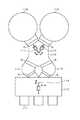
[第1の実施の形態]
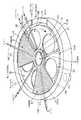
本発明の第1の実施の形態である成膜装置は、図1〜図3に示すように平面形状が概ね円形である扁平な真空容器1と、この真空容器1内に設けられ、当該真空容器1の中心に回転中心を有する回転テーブル2と、を備えている。真空容器1は、この回転テーブル2を収納する概略カップ型の容器本体12と、この容器本体12の上面の開口部を気密に塞ぐように円板状に形成された天板11と、を備えている。この天板11は、容器本体12の上面の周縁部にリング状に設けられたシール部材例えばOリング13を介して容器本体12側に気密に接続されており、図示しない開閉機構により昇降して開閉されるように構成されている。[First Embodiment]
The film forming apparatus according to the first embodiment of the present invention includes a
回転テーブル2は、中心部にて円筒形状のコア部21に固定されており、このコア部21は、鉛直方向に伸びる回転軸22の上端に固定されている。この回転軸22は、真空容器1の底面部14を貫通し、その下端が当該回転軸22を鉛直軸回りにこの例では時計回りに回転させる回転機構である駆動部23に取り付けられている。回転軸22及び駆動部23は、上面が開口した筒状のケース体20内に収納されている。このケース体20はその上面に設けられたフランジ部分が真空容器1の底面部14の下面に気密に取り付けられており、ケース体20の内部雰囲気と外部雰囲気との気密状態が維持されている。 The rotary table 2 is fixed to a
回転テーブル2の表面部には、図2及び図3に示すように回転方向(周方向)に沿って複数枚例えば5枚の基板である半導体ウェハ(以下「ウェハ」という)Wを載置するための円形状の凹部24が設けられており、この凹部24は回転テーブル2の回転により当該回転テーブル2の回転中心を中心として鉛直軸回りに公転するように構成されている。なお図3には便宜上1個の凹部24だけにウェハWを描いてある。ここで図4は、回転テーブル2を同心円に沿って切断しかつ横に展開して示す展開図であり、凹部24は、図4(a)に示すようにその直径がウェハWの直径よりも僅かに例えば4mm大きく、またその深さはウェハWの厚みと同等の大きさに設定されている。従ってウェハWを凹部24に落とし込むと、ウェハWの表面と回転テーブル2の表面(ウェハWが載置されない領域)とが揃うことになる。ウェハWの表面と回転テーブル2の表面との間の高さの差が大きいとその段差部分で圧力変動が生じることから、ウェハWの表面と回転テーブル2の表面との高さを揃えることが、膜厚の面内均一性を揃える観点から好ましい。ウェハWの表面と回転テーブル2の表面との高さを揃えるとは、同じ高さであるかあるいは両面の差が5mm以内であることをいうが、加工精度などに応じてできるだけ両面の高さの差をゼロに近づけることが好ましい。凹部24の底面には、ウェハWの裏面を支えて当該ウェハWを昇降させるための例えば後述する3本の昇降ピン16(図10参照)が貫通する貫通孔(図示せず)が形成されている。 As shown in FIGS. 2 and 3, a plurality of, for example, five semiconductor wafers (hereinafter referred to as “wafers”) W are placed on the surface of the
凹部24はウェハWを位置決めして回転テーブル2の回転に伴なう遠心力により飛び出さないようにするためのものであり、本発明の基板載置領域に相当する部位であるが、この基板載置領域(ウェハ載置領域)は、凹部に限らず例えば回転テーブル2の表面にウェハWの周縁をガイドするガイド部材をウェハWの周方向に沿って複数並べた構成であってもよく、あるいは回転テーブル2側に静電チャックなどのチャック機構を持たせてウェハWを吸着する場合には、その吸着によりウェハWが載置される領域が基板載置領域となる。 The
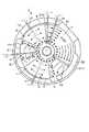
図2、図3及び図5に示すように、回転テーブル2における凹部24の通過領域と各々対向する上位置には、各々例えば石英からなる第1の反応ガスノズル31及び第2の反応ガスノズル32と、2本の分離ガスノズル41、42と、補助ノズル200と、が真空容器1の周方向(回転テーブル2の回転方向)に互いに間隔をおいて配置されている。この例では、後述の搬送口15から見て時計回り(回転テーブル2の回転方向)に分離ガスノズル41、第1の反応ガスノズル31、分離ガスノズル42、補助ノズル200及び第2の反応ガスノズル32がこの順番で配列されており、これらのノズル41、31、42、200、32は真空容器1の側壁において、この搬送口15に概略対向する位置から当該搬送口15の前記回転方向上流側に近接する位置まで順番に取り付けられている。これら反応ガスノズル31、32、補助ノズル200及び分離ガスノズル41、42は、例えば真空容器1の外周壁から回転テーブル2の回転中心に向かってウェハWに対向して水平に伸びるようにライン状に取り付けられており、その基端部であるガス導入ポート31a、32a、200a、41a、42aは当該外周壁を貫通している。 As shown in FIGS. 2, 3, and 5, the first
これら反応ガスノズル31、32、補助ノズル200は、夫々第1の反応ガス供給手段、第2の反応ガス供給手段及び補助ガス供給手段をなし、分離ガスノズル41、42は、分離ガス供給手段をなしている。これらのノズル31、32、200、41、42は、真空容器1の側壁の複数箇所に形成された貫通孔100に取り付けられている。尚、ノズル31、32、200、41、42が取り付けられていない貫通孔100は、図示しない覆い部材により気密に密閉されている。 The
反応ガスノズル31、32には、夫々図示しないバルブや流量調整部が介設されたガス供給管31b、32bにより、夫々第1の反応ガスであるBTBAS(ビスターシャルブチルアミノシラン、SiH2(NH−C(CH3)3)2)ガス及び第2の反応ガスであるO3(オゾン)ガスが供給されるように構成されている。補助ノズル200には、図示しないバルブや流量調整部が介設されたガス供給管200bにより、水酸基(OH基)を持つシラノール化用の補助ガス例えばアルコール(R−OH、R:アルキル基)又は純水(H2O)あるいは過酸化水素水(H2O2)この例ではエタノール(C2H5OH)ガスが供給されるように構成されている。また、分離ガスノズル41、41は、図示しないバルブや流量調整部が介設されたガス供給管により、分離ガスであるN2ガス(窒素ガス)が供給されるように構成されている。 The
反応ガスノズル31、32には、下方側に反応ガスを吐出するための例えば口径が0.5mmのガス吐出孔33が真下を向いてノズルの長さ方向(回転テーブル2の半径方向)に亘って例えば10mmの間隔を置いて等間隔に配列されている。また、補助ノズル200には、下方側に反応ガスを吐出するための例えば口径が0.5mmのガス吐出孔201が真下を向いてノズルの長さ方向(回転テーブル2の半径方向)に亘って例えば10mmの間隔を置いて等間隔に配列されている。分離ガスノズル41、42には、下方側に分離ガスを吐出するための例えば口径が0.5mmのガス吐出孔40が真下を向いて長さ方向に例えば10mm程度の間隔を置いて等間隔に穿設されている。 In the
反応ガスノズル31、32のガス吐出孔33とウェハWとの間の距離は例えば1〜4mm好ましくは2mmであり、補助ノズル200のガス吐出孔201とウェハWとの間の距離は例えば1〜4mm好ましくは2mmである。また、分離ガスノズル41、42のガス吐出孔40とウェハWとの間の距離は例えば1〜4mm好ましくは3mmである。反応ガスノズル31、32の下方領域は、夫々BTBASガスをウェハWに吸着させるための第1の処理領域91及びO3ガスをウェハWに吸着させるための第2の処理領域92となる。また、補助ノズル200の下方領域は、エタノールガスとウェハW上に吸着したBTBASガスとを反応させて中間生成物を生成させるための補助(処理)領域90となる。 The distance between the gas discharge holes 33 of the
分離ガスノズル41、42は、前記第1の処理領域91と補助領域90及び第2の処理領域92とを分離するための分離領域Dを形成するためのものであり、この分離領域Dにおける真空容器1の天板11には図2〜図4に示すように、回転テーブル2の回転中心を中心としかつ真空容器1の内周壁の近傍に沿って描かれる円を周方向に分割してなる、平面形状が扇型で下方に突出した凸状部4が設けられている。分離ガスノズル41、42は、この凸状部4における前記円の周方向中央にて当該円の半径方向に伸びるように形成された溝部43内に収められている。即ち分離ガスノズル41(42)の中心軸から凸状部4である扇型の両縁(回転テーブル2の回転方向上流側の縁及び下流側の縁)までの距離は同じ長さに設定されている。
尚、溝部43は、本実施形態では凸状部4を二等分するように形成されているが、他の実施形態においては、例えば溝部43から見て凸状部4における回転テーブル2の回転方向上流側が前記回転方向下流側よりも広くなるように溝部43を形成してもよい。The
In this embodiment, the
従って分離ガスノズル41、42における前記回転方向両側には、前記凸状部4の下面である例えば平坦な低い天井面44(第1の天井面)が存在し、この天井面44の前記回転方向両側には、当該天井面44よりも高い天井面45(第2の天井面)が存在することになる。この凸状部4の役割は、回転テーブル2との間に第1の反応ガス及び第2の反応ガスの侵入を阻止してこれら反応ガスの混合を阻止するための狭隘な空間である分離空間を形成することにある。
即ち、分離ガスノズル41を例にとると、回転テーブル2の回転方向上流側からエタノールガス及びO3ガスが侵入することを阻止し、また回転方向下流側からBTBASガスが侵入することを阻止する。「ガスの侵入を阻止する」とは、分離ガスノズル41から吐出した分離ガスであるN2ガスが第1の天井面44と回転テーブル2の表面との間に拡散して、この例では当該第1の天井面44に隣接する第2の天井面45の下方側空間に吹き出し、これにより当該隣接空間からのガスが侵入できなくなることを意味する。そして「ガスが侵入できなくなる」とは、隣接空間から凸状部4の下方側空間に全く入り込むことができない場合のみを意味するのではなく、多少侵入はするが、両側から夫々侵入したエタノールガス及びO3ガスとBTBASガスとが凸状部4内で交じり合わない状態が確保される場合も意味し、このような作用が得られる限り、分離領域Dの役割である補助領域90の雰囲気及び第1の処理領域91の雰囲気と第2の処理領域92の雰囲気との分離作用が発揮できる。従って狭隘な空間における狭隘の程度は、狭隘な空間(凸状部4の下方空間)と当該空間に隣接した領域(この例では第2の天井面45の下方空間)との圧力差が「ガスが侵入できなくなる」作用を確保できる程度の大きさになるように設定され、その具体的な寸法は凸状部4の面積などにより異なるといえる。またウェハWに吸着したガスについては当然に分離領域D内を通過することができ、ガスの侵入阻止は、気相中のガスを意味している。ここで、エタノールガスとO3ガスとの間には分離領域Dが設けられていないので、これらの両ガスは後述の排気口62に至るまでに互いに混じり合うが、ウェハWに悪影響を及ぼさない。Accordingly, for example, a flat low ceiling surface 44 (first ceiling surface) that is the lower surface of the
That is, taking the
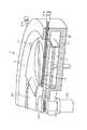
また、回転テーブル2の回転方向において、第2の反応ガスノズル32の下流側(第2の反応ガスノズル32とこの第2の反応ガスノズル32の回転方向下流側の分離領域Dとの間)には、回転テーブル2の半径方向に沿って伸びるように配置された加熱手段である加熱ランプ210が設けられている。この加熱ランプ210は、例えば棒状の赤外線ランプからなり、図6に示すように、真空容器1の天井部に回転テーブル2の半径方向に伸びるように形成されたランプハウス211内に設けられている。このランプハウス211は、上部側にリフレクター215が設けられ、下面側には当該ランプハウス211内の雰囲気と真空容器1内の雰囲気とを気密に区画するための光透過窓212が設けられている。この加熱ランプ210の両端には、電極部を兼用する封止部材213、213が設けられており、この封止部材213、213には例えば真空容器1の天板11の上方側から伸びる給電線214、214が各々接続されている。この図6中217はこの加熱ランプ210に給電線214、214及び封止部材213、213を介して給電するための電源であり、216はこの加熱ランプ210を両側から支持する支持部材である。また、この加熱ランプ210は、図示しない熱電対などの温度検出部の測定結果に基づいて、ウェハWに対して後述の加熱処理(緻密化処理)を行うのに好適な温度例えば100℃〜450℃好ましくは350℃に加熱できるように制御されている。尚、既述の図2では、このランプハウス211を省略して描画してある。 Further, in the rotation direction of the
この例では直径300mmのウェハWを被処理基板としており、この場合凸状部4は、回転テーブル2の回転中心から140mm外周側に離れた部位(後述の突出部5との境界部位)においては、周方向の長さ(回転テーブル2と同心円の円弧の長さ)が例えば146mmであり、ウェハWの載置領域(凹部24)の最も外側部位においては、周方向の長さが例えば502mmである。なお図4(a)に示すように、当該外側部位において分離ガスノズル41(42)の両脇から夫々左右に位置する凸状部4の周方向の長さLでみれば、長さLは246mmである。
また図4(a)に示すように凸状部4の下面即ち天井面44における回転テーブル2の表面までの高さhは、例えば0.5mmから10mmであってもよく、約4mmであると好適である。この場合、回転テーブル2の回転数は例えば1rpm〜500rpmに設定されている。そのため分離領域Dの分離機能を確保するためには、回転テーブル2の回転数の使用範囲などに応じて、凸状部4の大きさや凸状部4の下面(第1の天井面44)と回転テーブル2の表面との高さhを例えば実験などに基づいて設定することになる。なお分離ガスとしては、窒素(N2)ガスに限られずアルゴン(Ar)ガスなどの不活性ガスなどを用いることができるが、このようなガスに限らず水素(H2)ガスなどであってもよく、成膜処理に影響を与えないガスであれば、ガスの種類に関しては特に限定されるものではない。In this example, a wafer W having a diameter of 300 mm is used as the substrate to be processed. In this case, the
Further, as shown in FIG. 4A, the height h from the lower surface of the
一方天板11の下面には、回転テーブル2におけるコア部21よりも外周側の部位と対向するようにかつ当該コア部21の外周に沿って突出部5が設けられている。この突出部5は凸状部4における回転テーブル2の回転中心側の部位と連続して形成されており、その下面が凸状部4の下面(天井面44)と同じ高さに形成されている。図2及び図3は、前記天井面45よりも低くかつ分離ガスノズル41、42よりも高い位置にて天板11を水平に切断して示している。なお突出部5と凸状部4とは、必ずしも一体であることに限られるものではなく、別体であってもよい。
真空容器1の天板11の下面、つまり回転テーブル2のウェハ載置領域(凹部24)から見た天井面は既述のように第1の天井面44とこの天井面44よりも高い第2の天井面45とが周方向に存在するが、図1では、高い天井面45が設けられている領域についての縦断面を示しており、図7では、低い天井面44が設けられている領域についての縦断面を示している。扇型の凸状部4の周縁部(真空容器1の外縁側の部位)は図2及び図7に示されているように回転テーブル2の外端面に対向するようにL字型に屈曲して屈曲部46を形成している。扇型の凸状部4は天板11側に設けられていて、容器本体12から取り外せるようになっていることから、前記屈曲部46の外周面と容器本体12との間には僅かに隙間がある。この屈曲部46も凸状部4と同様に両側から反応ガスが侵入することを防止して、両反応ガスの混合を防止する目的で設けられており、屈曲部46の内周面と回転テーブル2の外端面との隙間、及び屈曲部46の外周面と容器本体12との隙間は、回転テーブル2の表面に対する天井面44の高さhと同様の寸法に設定されている。この例においては、回転テーブル2の表面側領域からは、屈曲部46の内周面が真空容器1の内周壁を構成していると見ることができる。On the other hand, a projecting
The bottom surface of the
容器本体12の内周壁は、分離領域Dにおいては図7に示すように前記屈曲部46の外周面と接近して垂直面に形成されているが、分離領域D以外の部位においては、図1に示すように例えば回転テーブル2の外端面と対向する部位から底面部14に亘って縦断面形状が矩形に切り欠かれて外方側に窪んだ構造になっている。この窪んだ部位における既述の第1の処理領域91及び第2の処理領域92に連通する領域を夫々第1の排気領域E1及び第2の排気領域E2と呼ぶことにすると、これらの第1の排気領域E1及び第2の排気領域E2の底部には、図1及び図3に示すように、夫々第1の排気口61及び第2の排気口62が形成されている。第1の排気口61及び第2の排気口62は、既述の図1に示すように、バルブ65が介設された排気路63を介して真空排気手段である例えば真空ポンプ64に接続されている。 As shown in FIG. 7, the inner peripheral wall of the container
これらの排気口61、62は、分離領域Dの分離作用が確実に働くように、平面で見たときに前記分離領域Dの前記回転方向両側に設けられている。詳しく言えば、回転テーブル2の回転中心から見て第1の処理領域91とこの第1の処理領域91に対して例えば回転方向下流側に隣接する分離領域Dとの間に第1の排気口61が形成され、回転テーブル2の回転中心から見て第2の処理領域92とこの第2の処理領域92に対して例えば回転方向下流側に隣接する分離領域Dとの間に第2の排気口62が形成されている。この排気口61はBTBASガスの排気を専用に行うように、また排気口62はエタノールガスとO3ガスとの排気を専用に行うようにその位置が設定されている。この例では一方の排気口61は、第1の反応ガスノズル31とこの反応ガスノズル31に対して前記回転方向下流側に隣接する分離領域Dの第1の反応ガスノズル31側の縁の延長線との間に設けられ、また他方の排気口62は、第2の反応ガスノズル32とこの反応ガスノズル32に対して前記回転方向下流側に隣接する分離領域Dの第2の反応ガスノズル32側の縁の延長線との間に設けられている。即ち、第1の排気口61は、図3中に一点鎖線で示した回転テーブル2の中心と第1の処理領域91とを通る直線L1と、回転テーブル2の中心と前記第1の処理領域91の下流側に隣接する分離領域Dの上流側の縁を通る直線L2との間に設けられ、第2の排気口62は、この図3に二点鎖線で示した回転テーブル2の中心と第2の処理領域92とを通る直線L3と、回転テーブル2の中心と前記第2の処理領域92の下流側に隣接する分離領域Dの上流側の縁を通る直線L4との間に位置している。 These
尚、排気口の設置数は2個に限られるものではなく、例えば分離ガスノズル42を含む分離領域Dと当該分離領域Dに対して前記回転方向下流側に隣接する第2の反応ガスノズル32との間に更に排気口を設置して3個としてもよいし、この場合にはノズル200、32の間の領域に排気口を設けても良い。更に、ノズル200、32の間の領域に分離領域Dを形成して、エタノールガスとO3ガスとを夫々専用に排気するようにしても良い。また、排気口の設置数は4個以上であってもよい。この例では排気口61、62は回転テーブル2よりも低い位置に設けることで真空容器1の内周壁と回転テーブル2の周縁との間の隙間から排気するようにしているが、真空容器1の底面部に設けることに限られず、真空容器1の側壁に設けてもよい。また排気口61、62は、真空容器1の側壁に設ける場合には、回転テーブル2よりも高い位置に設けるようにしてもよい。このように排気口61、62を設けることにより回転テーブル2上のガスは、回転テーブル2の外側に向けて流れるため、回転テーブル2に対向する天井面から排気する場合に比べてパーティクルの巻上げが抑えられるという観点において有利である。 Note that the number of exhaust ports is not limited to two. For example, the separation region D including the
前記回転テーブル2と真空容器1の底面部14との間の空間には、図1及び図8に示すように加熱手段であるヒータユニット7が設けられており、回転テーブル2を介して回転テーブル2上のウェハWをプロセスレシピで決められた温度に加熱するように構成されている。前記回転テーブル2の周縁付近の下方側には、回転テーブル2の上方空間から排気領域Eに至るまでの雰囲気とヒータユニット7が置かれている雰囲気とを区画するために、ヒータユニット7を全周に亘って囲むようにカバー部材71が設けられている。このカバー部材71は上縁が外側に屈曲されてフランジ形状に形成され、その屈曲面と回転テーブル2の下面との間の隙間を小さくして、カバー部材71内に外方からガスが侵入することを抑えている。 As shown in FIGS. 1 and 8, a
ヒータユニット7が配置されている空間よりも回転中心寄りの部位における底面部14は、回転テーブル2の下面の中心部付近、コア部21に接近してその間は狭い空間になっており、また当該底面部14を貫通する回転軸22の貫通穴についてもその内周面と回転軸22との隙間が狭くなっていて、これら狭い空間は前記ケース体20内に連通している。そして前記ケース体20にはパージガスであるN2ガスを前記狭い空間内に供給してパージするためのパージガス供給管72が設けられている。また真空容器1の底面部14には、ヒータユニット7の下方側位置にて周方向の複数部位に、ヒータユニット7の配置空間をパージするためのパージガス供給管73が設けられている。 The
このようにパージガス供給管72、73を設けることにより図9にパージガスの流れを矢印で示すように、ケース体20内からヒータユニット7の配置空間に至るまでの空間がN2ガスでパージされ、このパージガスが回転テーブル2とカバー部材71との間の隙間から排気領域Eを介して排気口61、62に排気される。これによって既述の第1の処理領域91と第2の処理領域92との一方から回転テーブル2の下方を介して他方にBTBASガスあるいはO3ガス(エタノールガス)の回り込みが防止されるため、このパージガスは分離ガスの役割も果たしている。 By providing the purge
また真空容器1の天板11の中心部には分離ガス供給管51が接続されていて、天板11とコア部21との間の空間52に分離ガスであるN2ガスを供給するように構成されている。この空間52に供給された分離ガスは、前記突出部5と回転テーブル2との間の狭い隙間50を介して回転テーブル2のウェハ載置領域側の表面に沿って周縁に向けて吐出されることになる。この突出部5で囲まれる空間には分離ガスが満たされているので、第1の処理領域91と第2の処理領域92との間で回転テーブル2の中心部を介して反応ガス(BTBASガスとO3ガス(エタノールガス))が混合することを防止している。即ち、この成膜装置は、第1の処理領域91の雰囲気と第2の処理領域92の雰囲気及び補助領域90の雰囲気とを分離するために回転テーブル2の回転中心部と真空容器1とにより区画され、分離ガスがパージされると共に当該回転テーブル2の表面に分離ガスを吐出する吐出口が前記回転方向に沿って形成された中心部領域Cを備えているということができる。なおここでいう吐出口は前記突出部5と回転テーブル2との狭い隙間50に相当する。 Further, a separation
更に真空容器1の側壁には図2、図3及び図10に示すように外部の搬送アーム10と回転テーブル2との間でウェハWの受け渡しを行うための搬送口15が形成されており、この搬送口15は図示しないゲートバルブにより開閉されるようになっている。また回転テーブル2におけるウェハ載置領域である凹部24はこの搬送口15に臨む位置にて搬送アーム10との間でウェハWの受け渡しが行われることから、回転テーブル2の下方側において当該受け渡し位置に対応する部位に、凹部24を貫通してウェハWを裏面から持ち上げるための受け渡し用の昇降ピン16の昇降機構(図示せず)が設けられる。 Further, as shown in FIGS. 2, 3, and 10, a
また、この成膜装置は、既述の図1に示すように、装置全体の動作のコントロールを行うためのコンピュータからなる制御部80を備えている。この制御部80は、CPU、メモリ及び処理プログラムを備えている。このメモリには、ノズル31、32、200、41、42から供給されるBTBASガス、O3ガス、エタノールガス及びN2ガスの流量、真空容器1内の処理圧力、ヒータユニット7及び加熱ランプ210に供給される電流値(ウェハWの加熱温度)などの処理条件が書き込まれる領域がレシピ毎に設けられている。上記の処理プログラムは、このメモリに書き込まれたレシピを読み出し、レシピに合わせて成膜装置の各部に制御信号を送り、後述の各ステップを進行させることでウェハWの処理を行うように命令が組み込まれている。このプログラムは、ハードディスク、コンパクトディスク、光磁気ディスク、メモリカード、フレキシブルディスクなどの記憶媒体である記憶部85から制御部80内にインストールされる。 Further, as shown in FIG. 1 described above, the film forming apparatus includes a control unit 80 including a computer for controlling the operation of the entire apparatus. The control unit 80 includes a CPU, a memory, and a processing program. In this memory, the flow rates of BTBAS gas, O3 gas, ethanol gas and N2 gas supplied from the
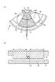
次に上述の第1の実施の形態の作用について、図11〜図14を参照して説明する。先ず、この成膜装置にて薄膜を成膜するウェハWについて説明すると、このウェハWの表面には、例えば溝状の凹部230が複数本平行に形成されており、図11では凹部230の形成されたウェハWの表面部の一部を断面で示してある。この凹部230のアスペクト比は、3〜50程度である。この凹部(パターン)230は、例えば既述のようにSTI(Shallow Trench Isolation)構造を形成するためのものであり、実際には例えば窒化シリコン化合物からなる導電膜に形成されている。また、このパターンは例えばウェハWの上層に積層されたマスク層を用いて例えばフォトリソグラフィ工程などにより形成されているので、この凹部230には、フォトリソグラフィ工程における処理の誤差などにより、下端側の開口寸法よりも上端側の開口寸法が広くなるテーパー部233や、下端側の開口寸法よりも上端側の開口寸法が狭くなる逆テーパー部234が形成されている場合がある。図11では、このような凹部230の形状のばらつきについては誇張して記載してある。 Next, the operation of the above-described first embodiment will be described with reference to FIGS. First, a description will be given of a wafer W on which a thin film is formed by this film forming apparatus. On the surface of the wafer W, for example, a plurality of groove-
次に、このウェハWに対する成膜処理について、以下に説明する。先ず、図示しないゲートバルブを開き、成膜装置の外部から搬送アーム10により搬送口15を介してウェハWを回転テーブル2の凹部24内に受け渡す。この受け渡しは、凹部24が搬送口15に臨む位置に停止したときに、搬送アーム10によりウェハWを昇降ピン16の上方位置に搬入し、次いで昇降ピン16が上昇してこのウェハWを受け取ることにより行われる。そして、搬送アーム10が真空容器1の外部に退避すると共に、昇降ピン16を下降させて凹部24内にウェハWを収納する。このようなウェハWの受け渡しを回転テーブル2を間欠的に回転させて行い、回転テーブル2の5つの凹部24内に夫々ウェハWを載置する。続いて、回転テーブル2を所定の回転数例えば240rpmで時計回りに回転させて、バルブ65を全開にして真空容器1内を真空引きすると共に、ヒータユニット7によりウェハWを設定温度例えば350℃に加熱する。また、その下方を通過するウェハWの最表面のみが例えば350℃以上に加熱されるように、加熱ランプ210に給電する。 Next, the film forming process for the wafer W will be described below. First, a gate valve (not shown) is opened, and the wafer W is transferred from the outside of the film forming apparatus to the
次いで、真空容器1内が所定の真空度となるようにバルブ65の開度を調整して、第1の反応ガスノズル31及び第2の反応ガスノズル32から真空容器1内に例えば夫々200sccm、10000sccmでBTBASガス及びO3ガスを供給すると共に、補助ノズル200から真空容器1内にエタノールガスを所定の流量例えば100sccmで供給する。また、分離ガスノズル41、42から例えば夫々10000sccm、10000sccmで真空容器1内にN2ガスを供給すると共に、分離ガス供給管51及びパージガス供給管72からも所定の流量でN2ガスを中心部領域C及び既述の狭い空間内に供給する。 Next, the degree of opening of the
そして、ウェハWは回転テーブル2の回転により、第1の処理領域91、補助領域90及び第2の処理領域92をこの順番で通過していく。ウェハWが第1の処理領域91を通過すると、このウェハWの表面には分子層が1層あるいは複数層のBTBASガスが吸着する。図12は、逆テーパー状の凹部230にシリコン酸化膜が埋め込まれていく様子を示しており、図12(a)はBTBASガスの分子層241の厚さを便宜上誇張して描画してある。次いで、このウェハWが補助領域90を通過すると、ウェハWの表面に吸着したBTBASガスの分子層241は、以下の反応式(1)に従って反応し(シラノール化され)、t−ブチルアミン(CH3C−NH2)と中間生成物であるシロキサン重合体(−(Si−O)n−)とを生成する。
BTBAS+C2H5OH →(−(Si−O)n−)+CH3C−NH2↑ (1)
このシロキサン重合体は、クラスター状であり、ウェハWに強く吸着していないため、ウェハWの表面(パターンの内部)にて粘性が高い状態となっていて流動しやすくなっている。そのため、図12(b)に示すように、このシロキサン重合体は重力の作用によって下方側が厚くなるように積層部分が流動するので、例えば逆テーパー状の凹部230においては、側面が垂直に近づくように、つまり末広がりの程度が緩和される。また、このシロキサン重合体と共に生成した有機物は、例えば気化してウェハWの上方に向かって排気されていく。Then, the wafer W passes through the
BTBAS + C2H5OH → (-(Si-O) n-) + CH3C-NH2 ↑ (1)
Since this siloxane polymer is in a cluster shape and is not strongly adsorbed to the wafer W, the siloxane polymer is in a highly viscous state on the surface of the wafer W (inside the pattern) and is easy to flow. For this reason, as shown in FIG. 12B, the siloxane polymer flows through the laminated portion so that the lower side becomes thick due to the action of gravity, so that, for example, in a reverse-tapered
そして、このウェハWが第2の処理領域92を通過すると、ウェハWの表面では上記のシロキサン重合体が酸化されて、シリコンと酸素とを含む反応生成物である例えば膜厚が0.1nm程度のシリコン酸化膜(SiO2膜)242が形成される。また、シリコン酸化膜242と共に生成した有機物などの不純物は、例えば気化してウェハWの上方に排気されていく。この時、反応前のシロキサン重合体が流動性を持っていることから、このサイクルで形成したシリコン酸化膜242の積層部分についても同様に流動性することになる。続いて、ウェハWが加熱ランプ210の下方領域に達するが、回転テーブル2が回転しているため直ぐに下流側に移動する。このため加熱ランプ210からウェハWに輻射熱が供給される時間は短いが、ウェハWの表層部分は一気に例えば350℃まで上昇し、この結果当該サイクルで形成されたシリコン酸化膜242の積層部分は、膜中のSi−O結合が多く形成されてSiOH結合が少なくなっていくと共に、いわば焼き締められて結合が強固になって緻密化していく。その後、ウェハWが加熱ランプ210の下方領域から下流側に移動すると、ウェハWの表層部は例えば下流側の分離領域Dで吹き付けられるN2ガスにより降温し、上記のように末広がりの程度が緩和された状態で固化することになる。 When the wafer W passes through the
更に、加熱ランプ210によりウェハWが加熱されるので、シリコン酸化膜242内に有機物などの不純物が残っていたとしても、気化して当該シリコン酸化膜242から離脱して排出されて行く。こうして、回転テーブル2の回転(サイクル)を多数回例えば20回行うことにより、分子層241の生成、シロキサン重合体の生成と流動、反応生成物(シリコン酸化膜242)の形成と流動及びシリコン酸化膜242の結合の緻密化が繰り返され、図12(c)に示すように段階的に逆テーパー形状が緩和されていき、図12(d)及び図13に示すように、凹部230内にシリコン酸化膜242が埋め込まれる。既述のように、反応生成物であるシリコン酸化膜242は、概略的な言い方をすれば各サイクル毎にシラノール化処理を行って流動させることにより逆テーパー形状が段階的に緩和されていくので、空隙のない状態で埋め込みが終了する。また、不純物がシリコン酸化膜242の膜中に入り込んでいる場合でも、不純物を含有している可能性のある成膜直後のシリコン酸化膜242が上記のように極めて薄いので、不純物は速やかに排出されることになる。 Further, since the wafer W is heated by the
上述の一連の工程中、第1の処理領域91と第2の処理領域92及び補助領域90との間においてN2ガスを供給し、また中心部領域Cにおいても分離ガスであるN2ガスを供給しているので、図14に示すようにBTBASガスとO3ガス及びエタノールガスとが混合しないように各ガスが排気されることとなる。また、分離領域Dにおいては、屈曲部46と回転テーブル2の外端面との間の隙間が既述のように狭くなっているので、BTBASガスとO3ガス及びエタノールガスとは、回転テーブル2の外側を介しても混合しない。従って、第1の処理領域91の雰囲気と第2の処理領域92の雰囲気及び補助領域90の雰囲気とが完全に分離され、BTBASガスは排気口61に、またO3ガス及びエタノールガスは排気口62に夫々排気される。この結果、BTBASガスとO3ガス及びエタノールガスとが雰囲気中においてもウェハW上においても混じり合うことがない。 During the series of steps described above, N2 gas is supplied between the
また、この例では反応ガスノズル31、32が配置されている第2の天井面45の下方側の空間に沿った容器本体12の内周壁においては、既述のように内周壁が切り欠かれて広くなっており、この広い空間の下方に排気口61、62が位置しているので、第1の天井面44の下方側の狭隘な空間及び前記中心部領域Cの各圧力よりも第2の天井面45の下方側の空間の圧力の方が低くなる。
なお、回転テーブル2の下方側をN2ガスによりパージしているため、排気領域Eに流入したガスが回転テーブル2の下方側を潜り抜けて、例えばBTBASガスがO3ガスの供給領域に流れ込むといったおそれは全くない。
尚、上記のように各領域91、90、92をウェハWが順番に通過するにあたって、ウェハWが回転テーブル2の回転方向に沿って5箇所の凹部24に配置されていることから、ウェハWは分子層241が形成される前にエタノールガスやO3ガスが供給されたり、あるいは加熱ランプ210により加熱されたりする場合もあるが、特に成膜には悪影響を及ぼさない。In this example, the inner peripheral wall of the
Since the lower side of the
In addition, since the wafer W is arrange | positioned at the five recessed
こうして成膜処理が終了すると、ガスの供給を停止して真空容器1内を真空排気し、その後回転テーブル2の回転を停止して各ウェハWを搬入時と逆の動作によって順次搬送アーム10により搬出する。
ここで処理パラメータの一例について記載しておくと、回転テーブル2の回転数は、300mm径のウェハWを被処理基板とする場合は例えば1rpm〜500rpm、真空容器1の中心部の分離ガス供給管51からのN2ガスの流量は例えば5000sccmである。When the film forming process is thus completed, the supply of gas is stopped and the inside of the
Here, an example of processing parameters will be described. The rotation speed of the
上述の実施の形態によれば、ウェハWの表面に2種類の反応ガス(BTBASガス及びO3ガス)を順番に供給して薄膜を形成するにあたり、ウェハW上にBTBASガスを吸着させた後、O3ガスを供給する前にエタノールガスを供給することによって、分子層241に対して流動性の高い状態(シロキサン重合体)が得られるようにしている。そのため、シロキサン重合体が流動し、また続くO3ガスによる酸化処理により生成したシリコン酸化膜242についても流動するので、シリコン酸化膜242が凹部230の内部へと入り込むため、凹部230が例えば逆テーパー状に形成されている場合であっても、凹部230内に空洞(ボイド)が介在しない状態でシリコン酸化膜242が埋め込むことができる。従って、良好に埋め込みが行われたシリコン酸化膜242を得ることができる。 According to the above-described embodiment, in order to form a thin film by sequentially supplying two kinds of reaction gases (BTBAS gas and O3 gas) to the surface of the wafer W, after the BTBAS gas is adsorbed on the wafer W, By supplying ethanol gas before supplying
この成膜方法は既述のようにALD(MLD)法に基づいた手法であることから、順次積層されていくシリコン酸化膜242(シロキサン重合体)を順番に流動させれば良いので、各サイクルでシリコン酸化膜242を流動させる量は僅かであり、従ってシリコン酸化膜242を速やかに流動させることができる。そのため、回転テーブル2が回転していることによりノズル200の下方領域におけるウェハWの滞在時間が短くても、既述のように逆テーパー形状が段階的に緩和されていくので、ボイド(空洞)のない埋め込みを達成でき、例えばSTI構造のデバイスを製造する場合には良好な絶縁特性を得ることができる。そしてALDを行うために回転テーブル2を回転させている各サイクルの中でシラノール化(流動)を行っているので、シラノール化を行うことによる時間的なロスがないため、高いスループットを維持できる。
また、シラノール化前にシリコン酸化膜242内に不純物が混入していたとしても、シリコン酸化膜242の膜厚が極めて薄い状態で回転テーブル2を回転させる度に加熱ランプ210により加熱していることから、不純物を速やかに除去すると共にシリコン酸化膜242を緻密化することができる。Since this film forming method is based on the ALD (MLD) method as described above, the silicon oxide film 242 (siloxane polymer) that is sequentially stacked may be flowed in order, so that each cycle. Therefore, the amount of flowing the
Even if impurities are mixed in the
更にまた、上記のように回転テーブル2の回転方向に複数のウェハWを配置し、回転テーブル2を回転させて領域91、90、92を順番に通過させていわゆるALD(あるいはMLD)を行うようにしているため、高いスループットで成膜処理を行うことができる。そして、前記回転方向において第1の処理領域91及び補助領域90と第2の処理領域92との間に低い天井面を備えた分離領域Dを設けると共に、回転テーブル2の回転中心部と真空容器1とにより区画した中心部領域Cから回転テーブル2の周縁に向けて分離ガスを吐出し、前記分離領域Dの両側に拡散する分離ガス及び前記中心部領域Cから吐出する分離ガスと共に前記反応ガスが回転テーブル2の周縁と真空容器の内周壁との隙間を介して排気されるようにしているため、両反応ガスの混合を防止することができ、この結果良好な成膜処理を行うことができるし、回転テーブル2上において反応生成物が生じることが全くないか極力抑えられ、パーティクルの発生が抑えられる。尚、本発明は、回転テーブル2に1個のウェハWを載置する場合にも適用できる。 Furthermore, as described above, a plurality of wafers W are arranged in the rotation direction of the
また、上記の例においては、成膜処理中に加熱ランプ210に給電を続けて、回転テーブル2の各回転毎(各サイクル毎)に反応生成物に対して加熱ランプ210による加熱処理を行うようにしたが、例えばBTBASガスの吸着、中間生成物の生成及びシリコン酸化膜242の生成を複数回例えば20回繰り返す毎に加熱ランプ210に給電して加熱処理を行うようにしても良い。
この場合には、回転テーブル2を複数回回転させて反応生成物の積層を複数回行った後、分離ガス以外の各ガスの供給を停止すると共に加熱ランプ210をオンにし、回転テーブル2を1回転させて各ウェハWを順番に加熱ランプ210の下方側を通過させる。このような例によっても各ウェハW上の凹部への埋め込みを良好に行うことができ、また成膜を中断して例えば回転テーブル2を1回転させることでリフローを行うことができるため、リフローを行うことにより消費される時間は極めて小さく、従ってこの例においても高いスループットが維持できる。そしてまたこのように反応生成物の積層を複数回行った後に加熱処理を行う例においては、回転テーブル2の各回転ごとにエタノールガスを供給して中間生成物を生成することに限らず、反応生成物の積層時にはエタノールガスの供給を停止しておき、加熱ランプ210により加熱処理を行うために回転テーブル2を回転させるときだけエタノールガスを供給するようにしてもよい。In the above example, power is continuously supplied to the
In this case, after rotating the rotary table 2 a plurality of times to stack the reaction products a plurality of times, the supply of each gas other than the separation gas is stopped, the
[第2の実施の形態]
次に、本発明の第2の実施の形態について、図15〜図17を参照して説明する。この実施の形態では、図15に示すように、回転テーブル2の回転方向において、既述の第2の反応ガスノズル32と加熱ランプ210との間にプラズマ供給手段であるプラズマインジェクター250が設けられている。
プラズマインジェクター250は、筐体からなるインジェクター本体251を備えている。図16、図17に示すように当該インジェクター本体251内には、隔壁252によって長さ方向に区画された幅の異なる2つの空間が形成されていて、一方側はプラズマ発生用のガスをプラズマ化するためのガス活性化用流路であるガス活性化室253、他方側はこのガス活性化室253へプラズマ発生用のガスを供給するためのガス導入用流路であるガス導入室254となっている。[Second Embodiment]
Next, a second embodiment of the present invention will be described with reference to FIGS. In this embodiment, as shown in FIG. 15, a
The
この図15〜図17において、255はガス導入ノズル、256はガス孔、257はガス導入ポート、258は継手部、259はガス供給ポートであり、ガス導入ノズル255からプラズマ発生用のガスがガス孔256から吐出してガス導入室254内に供給され、このガス導入室254から隔壁252の上部に形成された切り欠き部271を介してガス活性化室253にガスが通流するように構成されている。ガス活性化室253内には、2本の誘電体からなる例えばセラミックス製のシース管272、272が当該ガス活性化室253の基端側から先端側へ向けて隔壁252に沿って伸び出しており、これらのシース管272、272の管内には、棒状の電極273、273が貫挿されている。これらの電極273、273の基端側はインジェクター本体251の外部に引き出され、真空容器1の外部にて整合器274を介して高周波電源275と接続されている。インジェクター本体251の底面には、当該電極273、273の間の領域であるプラズマ発生部290にてプラズマ化して活性化されたプラズマを下方側に吐出するためのガス吐出孔291がインジェクター本体251の長さ方向に配列されている。このインジェクター本体251は、その先端側を回転テーブル2の中心部へ向けて伸び出した状態となるように配設されている。図15中262〜264はバルブ、265〜267流量調整部、268〜270は夫々プラズマ発生用のガス例えば酸素(O2)ガス、アルゴン(Ar)ガス及び水素(N2)ガスが貯留されたガス源である。 15 to 17,
この実施の形態の作用について以下に説明する。この実施の形態においても、同様に回転テーブル2上にウェハWを5枚載置して、この回転テーブル2を回転させて、各ガスノズル31、32、200、41、42からBTBASガス、O3ガス、エタノールガス及び窒素ガスをウェハWに向けて夫々供給すると共に、既述のようにパージガスを中心部領域Cや回転テーブル2の下方の領域に供給する。そして、ヒータユニット7及び加熱ランプ210に既述のように給電し、プラズマインジェクター250に対してプラズマ発生用のガス例えばArガスを供給すると共に、高周波電源275からプラズマ発生部290(電極273、273)に高周波電力を供給する。
一方、真空容器1内は真空雰囲気となっているので、ガス活性化室253の上方部へ流入したプラズマ発生用のガスは上記の高周波電力によりプラズマ化(活性化)された状態となってガス吐出孔291を介してウェハWに向けて供給される。The operation of this embodiment will be described below. Also in this embodiment, similarly, five wafers W are placed on the
On the other hand, since the inside of the
このプラズマが第2の処理領域92を通過して既述のシリコン酸化膜242が成膜されたウェハWに到達すると、当該シリコン酸化膜242内に残っていた炭素成分や水分が気化して排出されたり、あるいはシリコンと酸素との間の結合が強められたりすることになる。その後、このウェハWは加熱ランプ210の下方領域を通過して、既述のようにシリコン酸化膜242の結合が緻密化されることによって、凹部230内において逆テーパー形状が緩和されるようにシリコン酸化膜242が形成される。
このようにプラズマインジェクター250を設けることにより、既述の第1の実施の形態よりも更に不純物が少なく、また結合強度の強いシリコン酸化膜242を成膜することができる。When this plasma passes through the
By providing the
この例においては、上記のようにプラズマ発生用のガスとしてArガスを用いたが、このガスに代えて、あるいはこのガスと共にO2ガスやN2ガスを用いても良い。このArガスを用いた場合には、膜中のSiO2結合を作りSiOH結合をなくすという効果が得られて、またO2ガスを用いた場合には未反応部分の酸化を促進し、膜中のC(炭素)が減少して電気特性が向上するという効果が得られる。
この実施の形態においても、BTBASガスの吸着、中間生成物の生成及びシリコン酸化膜242の生成を複数回行う度に加熱ランプ210に給電して加熱処理を行うようにしても良いし、あるいはプラズマの供給を複数層のシリコン酸化膜242を積層する度に行っても良い。In this example, Ar gas is used as the plasma generating gas as described above, but O2 gas or N2 gas may be used instead of or together with this gas. When this Ar gas is used, the effect of creating SiO2 bonds in the film and eliminating the SiOH bonds can be obtained, and when O2 gas is used, oxidation of the unreacted portion is promoted and C in the film is promoted. The effect of improving the electrical characteristics by reducing (carbon) is obtained.
Also in this embodiment, the heat treatment may be performed by supplying power to the
[第3の実施の形態]
次に、本発明の第3の実施の形態について、図18を参照して説明する。この実施の形態では、シリコン酸化膜242が更に速やかに流動(リフロー)するように、シリコン酸化膜242中にホウ素(B)及びリン(P)の少なくとも一方が混入するようにしている。具体的な成膜装置として、既述の第1の実施の形態の成膜装置を例に挙げて説明すると、この成膜装置にはこれらのホウ素及びリンの少なくとも一方例えばリンを含む化合物例えばPH4(フォスフィン)ガスを第3の反応ガスとして供給するための第3の反応ガス供給手段である例えば石英製の第3のガスノズル150が設けられており、このノズル150は、回転テーブル2の回転方向において、例えば第2の反応ガスノズル32と加熱ランプ210との間に設けられている。[Third Embodiment]
Next, a third embodiment of the present invention will be described with reference to FIG. In this embodiment, at least one of boron (B) and phosphorus (P) is mixed in the
このノズル150は、既述の各ノズル31、32、200、41、42と同様に構成されており、真空容器1の外周壁から回転テーブル2の回転中心に向かってウェハWに対向して水平に伸びるように取り付けられ、その基端部であるガス導入ポート151は当該外周壁を貫通している。このノズル150には、図示しないバルブや流量調整部が介設されたガス供給管152により上記の第3の反応ガスが供給されるように構成されており、このノズル150の下方側には、この反応ガスを下方側のウェハWに向けて吐出するための例えば口径が0.5mmのガス吐出孔(図示せず)が真下を向いてノズルの長さ方向に亘って例えば10mmの間隔を置いて等間隔に配列されている。このノズル150のガス吐出孔とウェハWとの間の距離は例えば1〜4mm好ましくは2mmである。この例では、加熱ランプ210におけるウェハWの加熱温度は、例えば700℃〜800℃程度に設定される。 The
このノズル150を備えた成膜装置における作用について以下に説明する。既述のように、回転テーブル2上に例えば5枚のウェハWを載置して、この回転テーブル2を回転させると共に、各ノズル31、32、200、150、41、42から各反応ガス及び分離ガスを供給し、中心部領域C及び回転テーブル2の下方領域にパージガスを供給する。そして、第2の処理領域92を通過して表面にシリコン酸化膜242が形成されたウェハWに対して上記の第3の反応ガスが供給されると、この反応ガスが当該シリコン酸化膜242中に取り込まれる。次いで、加熱ランプ210の下方において、第3のガスが取り込まれたシリコン酸化膜242を上記のように700℃〜800℃程度に加熱すると、例えば第3の反応ガス中に含まれていた有機物が気化してこの膜から上方に向けて排気されていくと共に、このシリコン酸化膜242中に例えばリンが取り込まれることになる。この時、シリコン酸化膜242はリンによりガラス転移しやすくなるので、シリコン酸化膜242がリフロー(流動)して、更に逆テーパー状の凹部230の末広がりの程度が緩和されることになる。その後、既述の例と同様に多層のシリコン酸化膜242が積層されていく。 The operation of the film forming apparatus provided with the
このノズル150の配置位置としては、回転テーブル2の回転方向において第1の反応ガスノズル31と加熱ランプ210との間であれば良く、例えば第1の反応ガスノズル31のガス供給管31bにガス供給管152を介設してこの第3の反応ガスと既述のBTBASガスとの混合ガスを供給しても良い。また、この第3の反応ガスとしては、上記のガスに代えて、あるいはこのガスと共にホウ素を含む化合物例えばTMB(トリメチルボロン)ガスを供給し、シリコン酸化膜242中にリン及びホウ素の少なくとも一方を混入させるようにしても良い。更に、この例においても、加熱ランプ210と共にプラズマインジェクター250を設けても良い。 The arrangement position of the
上記の各例においては、補助ノズル200から供給する補助ガスとしてはエタノールガスを用いたが、他のアルコール例えばメタノール(CH3OH)などでも良いし、あるいは純水(H2O)や過酸化水素水(H2O2)などでも良く、つまり水酸基(OH)基を持つ化合物のガスであれば良い。この補助ガスとして純水を用いた場合には、この純水のガスとウェハWの表面に吸着したBTBASガスとは、例えば以下の(2)式に従って反応してシラノール化する。
BTBAS+H2O →(−SiO−)n +CH3C−NH2↑ (2)
この反応において生成する中間生成物である(−SiO−)nは、既述のシロキサン重合体と同様に流動性を示し、またこの(−SiO−)nとO3ガスとが反応して生成するシリコン酸化膜242は、同様に流動性を示すので流動して良好に凹部230が埋め込まれることになる。In each of the above examples, ethanol gas is used as the auxiliary gas supplied from the
BTBAS + H2O → (-SiO-) n + CH3C-NH2 ↑ (2)
The intermediate product (—SiO—) n produced in this reaction exhibits fluidity in the same manner as the siloxane polymer described above, and this (—SiO—) n reacts with
また、上記の各例では、表面に凹部230が形成されたウェハWに対して本発明を適用したが、このような凹部230が形成されたウェハW以外にも、例えばシリコン酸化膜242のベタ膜を形成する場合に本発明を適用しても良い。この場合には、不純物の濃度が低く、緻密な膜質が良好な薄膜を得ることができる。 In each of the above examples, the present invention is applied to the wafer W having the
また、真空容器1内において中央部では昇温しやすく、逆に周縁部では昇温しにくいことから、加熱ランプ210を回転テーブル2の半径方向に複数例えば3つのヒーターに区画し、例えば中央部側よりも周縁部側に給電する電力量が大きくなるようにこれらのヒーターを個別に制御しても良い。更に、この加熱ランプ210としては、各ノズル31、32、200、41、42やプラズマインジェクター250と同様に、真空容器1の側壁の貫通孔100から真空容器1の中心に向けて気密に挿入するように構成しても良い。 Further, in the
本発明で適用される処理ガス(第1の反応ガス)としては、上述の例の他に、DCS[ジクロロシラン]、HCD[ヘキサクロロジシラン]、TMA[トリメチルアルミニウム]、3DMAS[トリスジメチルアミノシラン]、TEMAZ[テトラキスエチルメチルアミノジルコニウム]、TEMHF[テトラキスエチルメチルアミノハフニウム]、Sr(THD)2 [ストロンチウムビステトラメチルヘプタンジオナト]、Ti(MPD)(THD)[チタニウムメチルペンタンジオナトビステトラメチルヘプタンジオナト]、モノアミノシランなどを挙げることができる。
また、前記分離領域Dの天井面44において、前記分離ガスノズル41、42に対して回転テーブル2の回転方向の上流側部位は、外縁に位置する部位ほど前記回転方向の幅が大きいことが好ましい。その理由は回転テーブル2の回転によって上流側から分離領域Dに向かうガスの流れが外縁に寄るほど速いためである。この観点からすれば、上述のように凸状部4を扇型に構成することは得策である。As the processing gas (first reaction gas) applied in the present invention, in addition to the above example, DCS [dichlorosilane], HCD [hexachlorodisilane], TMA [trimethylaluminum], 3DMAS [trisdimethylaminosilane], TEMAZ [tetrakisethylmethylaminozirconium], TEMHF [tetrakisethylmethylaminohafnium], Sr (THD) 2 [strontium bistetramethylheptanedionato], Ti (MPD) (THD) [titanium methylpentanedionatobistetramethylheptane And diato] and monoaminosilane.
In addition, on the
そして、前記分離ガスノズル41(42)の両側に各々位置する狭隘な空間を形成する前記第1の天井面44は、図19(a)、(b)に前記分離ガスノズル41を代表して示すように例えば300mm径のウェハWを被処理基板とする場合、ウェハWの中心WOが通過する部位において回転テーブル2の回転方向に沿った幅寸法Lが50mm以上であることが好ましい。凸状部4の両側から当該凸状部4の下方(狭隘な空間)に反応ガスが侵入することを有効に阻止するためには、前記幅寸法Lが短い場合にはそれに応じて第1の天井面44と回転テーブル2との間の距離hも小さくする必要がある。更に第1の天井面44と回転テーブル2との間の距離hをある寸法に設定したとすると、回転テーブル2の回転中心から離れる程、回転テーブル2の速度が速くなってくるので、反応ガスの侵入阻止効果を得るために要求される幅寸法Lは回転中心から離れる程長くなってくる。このような観点から考察すると、ウェハWの中心WOが通過する部位における前記幅寸法Lが50mmよりも小さいと、第1の天井面44と回転テーブル2との距離hをかなり小さくする必要があるため、回転テーブル2を回転したときに回転テーブル2あるいはウェハWと天井面44との衝突を防止するために、回転テーブル2の振れを極力抑える工夫が要求される。更にまた回転テーブル2の回転数が高い程、凸状部4の上流側から当該凸状部4の下方側に反応ガスが侵入しやすくなるので、前記幅寸法Lを50mmよりも小さくすると、回転テーブル2の回転数を低くしなければならず、スループットの点で得策ではない。従って幅寸法Lが50mm以上であることが好ましいが、50mm以下であっても本発明の効果が得られないというものではない。即ち、前記幅寸法LがウェハWの直径の1/10〜1/1であることが好ましく、約1/6以上であることがより好ましい。 The
また本発明では分離ガス供給手段における回転方向両側に低い天井面44が位置することが好ましいが、分離ガスノズル41、42の両側に凸状部4を設けずに、分離ガスノズル41、42から下方に向けてN2ガスを吹き出してエアカーテンを形成し、このエアカーテンにより処理領域91、92を分離するようにしても良い。
ウェハWを加熱するための加熱手段としては抵抗発熱体を用いたヒータに限られずランプ加熱装置であってもよく、回転テーブル2の下方側に設ける代わりに回転テーブル2の上方側に設けてもよいし、上下両方に設けてもよい。また、上記の反応ガスによる反応が低温例えば常温において起こる場合には、このような加熱手段を設けなくとも良い。Further, in the present invention, it is preferable that the low ceiling surfaces 44 are located on both sides of the separation gas supply means in the rotation direction, but without providing the
The heating means for heating the wafer W is not limited to a heater using a resistance heating element, and may be a lamp heating device, and may be provided above the
ここで処理領域91、92及び分離領域の各レイアウトについて上記の実施の形態以外の他の例を挙げておく。分離領域Dは、扇型の凸状部4を周方向に2つに分割し、その間に分離ガスノズル41(42)を設ける構成であってもよいことを既に述べたが、図20は、既述の第1の実施の形態の成膜装置を例に挙げてこのような構成の一例を示す平面図である。この場合、扇型の凸状部4と分離ガスノズル41(42)との距離や扇型の凸状部4の大きさなどは、分離ガスの吐出流量や反応ガスの吐出流量などを考慮して分離領域Dが有効な分離作用が発揮できるように設定される。
上述の実施の形態では、前記第1の処理領域91及び第2の処理領域92は、その天井面が前記分離領域Dの天井面よりも高い領域に相当するものであったが、本発明は、第1の処理領域91及び第2の処理領域92の少なくとも一方は、分離領域Dと同様に反応ガス供給手段の前記回転方向両側にて前記回転テーブル2に対向して設けられ、当該回転テーブル2との間にガスの侵入を阻止するための空間を形成するようにかつ前記分離領域Dの前記回転方向両側の天井面(第2の天井面45)よりも低い天井面例えば分離領域Dにおける第1の天井面44と同じ高さの天井面を備えている構成としてもよい。Here, other examples than the above embodiment will be given for the layouts of the
In the above-described embodiment, the
また、反応ガスノズル31(32)の両側にも低い天井面を設けて、分離ガスノズル41(42)及び反応ガスノズル31(32)が設けられる箇所以外は、回転テーブル2に対向する領域全面に凸状部4を設ける構成としても良い。
また、各ノズル31、32、200、41、42(310)の取り付け位置を変更しても良く、各々の反応ガスが混じり合わないように排気されながら、ウェハWの表面にBTBASが吸着し、その後エタノールガスにより中間生成物が生成し、続いてO3ガスにより中間生成物が酸化されるサイクルが多数回繰り返されるように構成しても良い。Further, a low ceiling surface is provided on both sides of the reaction gas nozzle 31 (32), and the entire surface of the region facing the
Further, the mounting positions of the
[第4の実施の形態]
また、上記の各実施の形態の成膜装置としては、ガス供給系(ノズル31、32、200、41、42)に対して回転テーブル2を鉛直軸回りに回転させる構成としたが、ガス供給系が回転テーブル2に対して鉛直軸回りに回転する構成としても良い。つまり、ガス供給系と回転テーブル2とが相対的に回転する構成であれば良い。このような具体的な装置構成について、図21〜図24を参照して説明する。尚、既述の成膜装置と同じ部位については、同じ符号を付して説明を省略する。[Fourth Embodiment]
Further, in the film forming apparatus of each of the above embodiments, the rotary table 2 is rotated about the vertical axis with respect to the gas supply system (
真空容器1内には、既述の回転テーブル2に代えて、テーブルであるサセプタ300が配置されている。このサセプタ300の底面中央には、回転軸22の上端側が接続されており、ウェハWの搬入出を行うときにはサセプタ300を回転できるように構成されている。このサセプタ300上には、既述の凹部24が周方向に亘って複数箇所例えば5箇所に形成されている。 In the
図21〜図23に示すように、既述のノズル31、32、200、41、42は、サセプタ300の中央部の直上に設けられた扁平な円盤状のコア部301に取り付けられており、基端部が当該コア部301の側壁を貫通している。コア部301は後述するように例えば鉛直軸回りに反時計方向に回転するように構成されており、当該コア部301を回転させることによって各ガス供給ノズル31、32、200、41、42をサセプタ300の上方位置において回転させることができるようになっている。従って、例えばサセプタ300上のある1つのウェハWからガス供給系(ノズル31、32、200、41、42)を見た時にこれらのノズル31、32、200、41、42が向かってくる方向をサセプタ300の相対的回転方向下流側、ノズル31、32、200、41、42が遠ざかっていく方向を相対的回転方向上流側と呼ぶと、この成膜装置では、既述の図1に示した成膜装置と同様に、各ウェハWに対してBTBASガス、エタノールガス、O3ガスが分離領域Dを介してこの順番で供給されるように各ノズル31、32、200、41、42が配置されている。尚、図22は、真空容器1(天板11及び容器本体12)並びに天板11の上面に固定された後述のスリーブ304を取り去った状態を示している。 As shown in FIGS. 21 to 23, the
既述の凸状部4は、上記のコア部301の側壁部に固定されており、各ガス供給ノズル31、32、200、41、42と共にサセプタ300上を回転できるように構成されている。コア部301の側壁部には、図22、図23に示すように、各反応ガス供給ノズル31、32の回転方向上流側であって、当該上流側に設けられている凸状部4とコア部301との接合部の手前の位置に、2つの排気口61、62が設けられている。これら排気口61、62は各々後述の排気管302に接続されていて、反応ガス及び分離ガスを各処理領域91、92(90)から排気する役割を果たす。排気口61、62は、既述の例と同様に、分離領域Dの前記回転方向両側に設けられ、各反応ガス(BTBASガス及びO3ガス(エタノールガス))の排気を専用に行うようにしている。The above-described
また、既述の加熱ランプ210は、第2の反応ガスノズル32における前記相対的回転方向下流側に設けられており、基端側(回転中心側)がコア部301に接続されて各ノズル31、32、200、41、42と共に回転できるように支持されている。この場合には給電線214は、図示を省略するが、例えばコア部301の中心部を上方に向かって延伸して、後述の回転筒303の回転中心を通って給電されるように構成されている。尚、この例においても、加熱ランプ210はランプハウス内に設けられているが、ランプハウスの図示を省略している。 The
図21に示すように、コア部301の上面中央部には円筒状の回転筒303の下端部が接続されており、真空容器1の天板11上に固定されたスリーブ304内にて当該回転筒303を回転させることにより、真空容器1内でコア部301と共にノズル31、32、200、41、42、加熱ランプ210及び凸状部4を回転させる構成となっている。コア部301内は下面側が開放された空間となっていて、コア部301の側壁を貫通した反応ガス供給ノズル31、32、200、分離ガス供給ノズル41、42は、当該空間において各々BTBASガスを供給する第1の反応ガス供給管305、O3ガスを供給する第2の反応ガス供給管306、エタノールガスを供給する第3の反応ガス供給管401、分離ガスであるN2ガスを供給する分離ガス供給管307、308と接続されている(便宜上、図21には、分離ガス供給管307、308のみを図示してある)。
各供給管305〜308、401は、コア部301の回転中心近傍、詳細には後述の排気管302の周囲にてL字に屈曲されて上方に向けて伸び、コア部301の天井面を貫通して、垂直上方へ向けて円筒状の回転筒303内を延伸されている。As shown in FIG. 21, a lower end portion of a cylindrical
Each of the
図21、図22、図23に示すように、回転筒303は外径の異なる2つの円筒を上下2段に積み重ねた外観形状に構成されており、外径の大きな上段側の円筒の底面をスリーブ304の上端面にて係止させることにより、当該回転筒303を上面側から見て周方向に回転可能な状態でスリーブ304内に挿入する一方、回転筒303の下端側は天板11を貫通してコア部301の上面と接続されている。
天板11の上方位置における回転筒303の外周面側には、当該外周面の周方向の全面に亘って形成された環状流路であるガス拡散路が上下方向に間隔をおいて配置されている。本例においては、上段側から順番に分離ガス(N2ガス)を拡散させるための分離ガス拡散路309、BTBASガスを拡散させるための第1の反応ガス拡散路310、O3ガスを拡散させるための第2の反応ガス拡散路311、エタノールガスを拡散させるための第3の反応ガス拡散路402が配置されている。図中、312は回転筒303の蓋部であり、313は当該蓋部312と回転筒303とを密着させるOリングである。As shown in FIGS. 21, 22, and 23, the
On the outer peripheral surface side of the
各ガス拡散路309〜311、402には、回転筒303の全周に亘り、当該回転筒303の外面へ向けて開口するスリット320、321、322、403が設けられており、夫々のガス拡散路309〜311、402には、これらのスリット320、321、322、403を介して各種のガスが供給されるようになっている。一方、回転筒303を覆うスリーブ304には、各スリット320、321、322、403に対応する高さ位置に、ガス供給口であるガス供給ポート323、324、325、404が設けられており、不図示のガス供給源よりこれらのガス供給ポート323、324、325、404へと供給されたガスは、当該各ポート323、324、325、404に向けて開口するスリット320、321、322、403を介して各ガス拡散路309、310、311、402内に供給されることとなる。 In each
ここでスリーブ304内に挿入された回転筒303の外径は、当該回転筒303が回転可能な範囲で、可能な限りスリーブ304の内径と近い大きさに形成されており、前記各ポート323、324、325、404の開口部以外の領域においては、各スリット320、321、322、403はスリーブ304の内周面によって塞がれた状態となっている。この結果、各ガス拡散路309、310、311、402に導入されたガスは、当該ガス拡散路309、310、311、402内のみを拡散して、例えば他のガス拡散路309、310、311、402や真空容器1内、成膜装置の外部などに漏れ出さないようになっている。図21中、326は回転筒303とスリーブ304との隙間からのガス漏れを防止するための磁気シールであり、これら磁気シール326は各ガス拡散路309、310、311、402の上下にも設けられていて、各種ガスをガス拡散路309、310、311、402内に確実に封止する構成となっているが同図では便宜上省略してある。また、図24においても磁気シール326の記載は省略してある。 Here, the outer diameter of the
図24に示すように、回転筒303の内周面側において、ガス拡散路309にはガス供給管307、308が接続され、各ガス拡散路310、311には既述の各ガス供給管305、306が夫々接続されている。また、ガス拡散路402にはガス供給管401に接続されている。これによりガス供給ポート323から供給された分離ガスは、ガス拡散路309内を拡散してガス供給管307、308を介してノズル41、42へと流れ、また各ガス供給ポート324、325から供給された各種反応ガスは、夫々ガス拡散路310、311内を拡散し、ガス供給管305、306を介して各ノズル31、32へと流れ、真空容器1内に供給されるようになっている。また、ガス供給ポート404から供給されたエタノールガスは、ガス拡散路402及びガス供給管401を介してノズル200から真空容器1内に供給される。なお、図24においては図示の便宜上、後述の排気管302の記載は省略してある。 As shown in FIG. 24,
ここで図24に示すように、分離ガス拡散路309にはさらにパージガス供給管330が接続されており、当該パージガス供給管330は回転筒303内を下方側に延伸されて図23に示すようにコア部301内の空間に開口しており、当該空間内にN2ガスを供給することができる。ここで例えば図21に示すようにコア部301は、サセプタ300の表面から例えば既述の高さhの隙間を空けて浮いた状態となるように回転筒303に支持されており、サセプタ300に対してコア部301が固定されていないことにより自由に回転させることができる。しかしながらこのようにサセプタ300とコア部301との間に隙間が開いていると、例えば既述の処理領域91、92の一方からコア部301の下方を介して他方にBTBASガスあるいはO3ガスが回り込むおそれがある。Here, as shown in FIG. 24, a purge
そこでコア部301の内側を空洞とし、当該空洞の下面側をサセプタ300に向けて開放すると共に、当該空洞内にパージガス供給管330からパージガス(N2ガス)を供給して、前記隙間を介して各処理領域91、92へ向けてパージガスを吹き出させることにより、前述の反応ガスの回り込みを防止することができる。即ち、この成膜装置は、処理領域91、92の雰囲気を分離するためにサセプタ300の中心部と真空容器1とにより区画され、当該サセプタ300の表面にパージガスを吐出する吐出口がコア部301の回転方向に沿って形成された中心部領域Cを備えているということができる。この場合にパージガスは、コア部301の下方を介して他方にBTBASガスあるいはO3ガスが回り込むことを防止するための分離ガスの役割を果たしている。なおここでいう吐出口はコア部301の側壁とサセプタ300との間の隙間に相当する。Therefore, the inside of the
図21に示すように、回転筒303の上段側の外径の大きな円筒部の側周面には、駆動ベルト335が巻き掛けられており、この駆動ベルト335は、真空容器1の上方に配置された回転機構である駆動部336により、この駆動ベルト335を介して当該駆動部336の駆動力をコア部301に伝達し、これによりスリーブ304内の回転筒303を回転させることができる。尚、図21中337は、真空容器1の上方位置において駆動部336を保持するための保持部である。
回転筒303内には、その回転中心に沿って排気管302が配設されている。排気管302の下端部は、コア部301の上面を貫通してコア部301内の空間に伸びだしていて、その下端面は封止されている。一方、当該コア部301内に伸びだした排気管302の側周面には、例えば図23に示すように、各排気口61、62と接続された排気引込管341、342が設けられていて、パージガスで満たされたコア部301内の雰囲気とは隔離して各処理領域91、92(90)からの排ガスを排気管302内へと引き込むことができるようになっている。なお、既述のように図24においては排気管302の記載は省略してあるが、当該図24に記載された各ガス供給管305、306、307、308、401並びにパージガス供給管330は、この排気管302の周囲に配置されている。
図21に示すように排気管302の上端部は回転筒303の蓋部312を貫通し、真空排気手段である例えば真空ポンプ343に接続されている。なお図21中、344は下流側の配管に対して排気管302を回転可能に接続するロータリージョイントである。As shown in FIG. 21, a
An
As shown in FIG. 21, the upper end portion of the
この装置を用いた成膜処理の流れについて、既述の実施の形態の作用と異なる点について、以下に簡単に説明する。先ず、真空容器1内にウェハWを搬入する時には、サセプタ300を間欠的に回転させて、搬送アーム10と昇降ピン16との協働作業により5つの凹部24にウェハWを各々載置する。
そして、成膜装置に対してシリコン酸化膜242の成膜処理を行う時には、回転筒303を反時計回りに回転させる。すると、図24に示すように回転筒303に設けられた各ガス拡散路309〜311、402は回転筒303の回転に伴って回転するが、これらのガス拡散路309〜311、402に設けられたスリット320〜322、403の一部が各々対応するガス供給ポート323〜325、404の開口部へ向けて常時開口していることにより、ガス拡散路309〜311、402には各種のガスが連続的に供給される。Regarding the flow of the film forming process using this apparatus, the difference from the operation of the above-described embodiment will be briefly described below. First, when the wafer W is loaded into the
Then, when performing the film forming process of the
ガス拡散路309〜311、402に供給された各種のガスは、各々のガス拡散路309〜311、402に接続されたガス供給管305〜308、401を介して反応ガス供給ノズル31、32、200、分離ガス供給ノズル41、42より各処理領域91、92、90、分離領域Dへと供給される。これらのガス供給管305〜308、401は回転筒303に固定され、また、反応ガス供給ノズル31、32、200及び分離ガス供給ノズル41、42についてはコア部301を介して回転筒303に固定されていることから、回転筒303の回転に伴ってこれらのガス供給管305〜308、401及び各ガス供給ノズル31、32、200、41、42も回転しながら各種のガスを真空容器1内に供給している。また、加熱ランプ210についてもこれらの各ノズル31、32、200、41、42と共に回転し、ウェハWの上方領域を通過するときに、下方側のウェハWを既述の例と同様に加熱する。 Various gases supplied to the
このとき、回転筒303と一体となって回転しているパージガス供給管330からも分離ガスであるN2ガスを供給し、これにより中心部領域Cから即ちコア部301の側壁部とサセプタ300の中心部との間からサセプタ300の表面に沿ってN2ガスが吐出する。またこの例では反応ガス供給ノズル31、32が配置されている第2の天井面45の下方側の空間に沿ったコア部301の側壁部に排気口61、62が位置しているので、第1の天井面44の下方側の狭隘な空間及び前記中心部領域Cの各圧力よりも第2の天井面45の下方側の空間の圧力の方が低くなっている。そのため、BTBASガスとO3ガス及びエタノールガスとは、既述の成膜装置と同様に互いに混じり合うことなしに独立して排気されていくことになる。
従って、サセプタ300上で停止している各々のウェハWから見ると、各処理領域91、90、92が順番に通過することになり、既述のようにBTBASガスの吸着、エタノールガスの供給、O3ガスによる酸化処理及び加熱処理がこの順番で行われる。At this time, N2 gas as separation gas is also supplied from the purge
Accordingly, when viewed from each wafer W stopped on the
この実施の形態においても、同様に凹部230内にシリコン酸化膜242内が良好に埋め込まれて、同様の効果が得られる。また、このような成膜装置においても、第3の反応ガスノズル150を設けても良く、その場合にはこれらのノズル150には、この実施の形態における各ガスノズル31、32、200、41、42と同様に回転筒303内に収納されたガス供給管が接続され、スリーブ304に形成されたスリットを介して第3の反応ガスが供給されることになる。更に、この成膜装置101に既述のプラズマインジェクター250を設けても良い。 Also in this embodiment, similarly, the inside of the
次に、上記の成膜装置を備えた基板処理装置の全体構成について図25に示しておく。図25中、111は例えば25枚のウェハWを収納するフープと呼ばれる密閉型の搬送容器、112は搬送アーム113が配置された大気搬送室、114、115は大気雰囲気と真空雰囲気との間で雰囲気が切り替え可能なロードロック室(予備真空室)、116は2基の搬送アーム117、117(既述の搬送アーム10)が配置された真空搬送室、118、119は本発明の成膜装置である。 Next, FIG. 25 shows the entire configuration of the substrate processing apparatus provided with the film forming apparatus. In FIG. 25, for example, 111 is a hermetic transfer container called a hoop for storing 25 wafers W, 112 is an atmospheric transfer chamber in which the
次に、この基板処理装置における処理の流れについて説明する。搬送容器111は図示しない載置台を備えた搬入搬出ポートに外部から搬送され、大気搬送室112に接続された後、図示しない開閉機構により蓋が開けられて搬送アーム113により当該搬送容器111内からウェハWが取り出される。次いで、ウェハWはロードロック室114(115)内に搬入されて、当該室内が大気雰囲気から真空雰囲気に切り替えられた後、搬送アーム117により成膜装置118、119の一方に搬入され、既述の成膜処理が行われる。
上記の基板処理装置によれば、例えば5枚処理用の成膜装置を複数個例えば2個備えることにより、いわゆるALD(MLD)を高いスループットで実施することができる。Next, the flow of processing in this substrate processing apparatus will be described. The
According to the substrate processing apparatus, so-called ALD (MLD) can be performed with high throughput by providing, for example, two, for example, two film forming apparatuses for processing five sheets.
1 真空容器
2 回転テーブル
D 分離領域
W ウェハ
90 補助領域
91 第1の処理領域
92 第2の処理領域
200 補助ノズル
210 加熱ランプ
241 分子層
242 シリコン酸化膜DESCRIPTION OF
Claims (14)
Translated fromJapanese前記真空容器内のテーブルの表面に基板を載置するために設けられた基板載置領域と、
前記複数の反応ガス供給手段から夫々反応ガスが供給される複数の処理領域を基板が順番に位置するように前記テーブルと前記複数の反応ガス供給手段とを相対的に回転させる回転機構と、
前記テーブル上の基板載置領域に対向するように設けられ、前記基板に第1の反応ガスを供給してこの第1の反応ガスを吸着させるための第1の反応ガス供給手段と、
前記テーブル上の基板載置領域に対向するようにかつ前記テーブルの周方向において前記第1の反応ガス供給手段よりも前記複数のガス供給手段に対する前記テーブルの相対的回転方向下流側に離間して設けられ、前記基板に吸着した前記第1の反応ガスと反応して流動性を持つ中間生成物を生成する補助ガスを前記基板に供給するための補助ガス供給手段と、
前記テーブル上の基板載置領域に対向するようにかつ前記テーブルの周方向において前記補助ガス供給手段よりも前記相対的回転方向下流側に設けられ、前記基板上の前記中間生成物と反応して反応生成物を生成する第2の反応ガスを前記基板に供給するための第2の反応ガス供給手段と、
前記テーブル上の基板載置領域に対向するようにかつ前記テーブルの周方向において前記第2の反応ガス供給手段よりも前記相対的回転方向下流側であって前記第1の反応ガス供給手段よりも前記相対的回転方向上流側に設けられ、前記反応生成物を緻密化するために前記基板を加熱する加熱手段と、を備えたことを特徴とする成膜装置。A substrate is placed on a table in a vacuum vessel, and the table and a plurality of reaction gas supply means for supplying at least two types of reaction gases that react with each other are rotated relative to the substrate. In the film forming apparatus for supplying the at least two kinds of reaction gases in order and forming a thin film by laminating the reaction product layers by executing this supply cycle,
A substrate placement area provided for placing a substrate on the surface of the table in the vacuum vessel;
A rotation mechanism that relatively rotates the table and the plurality of reaction gas supply units so that the substrate is positioned in order in a plurality of processing regions to which reaction gases are supplied from the plurality of reaction gas supply units, respectively.
A first reaction gas supply means provided to face the substrate placement region on the table, for supplying a first reaction gas to the substrate and for adsorbing the first reaction gas;
It is opposed to the substrate placement area on the table and is spaced further downstream in the rotational direction of the table relative to the plurality of gas supply means than the first reaction gas supply means in the circumferential direction of the table. An auxiliary gas supply means for supplying the substrate with an auxiliary gas that is provided and reacts with the first reaction gas adsorbed on the substrate to generate a fluid intermediate product;
It is provided in the circumferential direction of the table so as to face the substrate placement area on the table and on the downstream side in the relative rotation direction with respect to the auxiliary gas supply means, and reacts with the intermediate product on the substrate. Second reaction gas supply means for supplying a second reaction gas for generating a reaction product to the substrate;
In the circumferential direction of the table so as to face the substrate placement region on the table and in the relative rotational direction downstream of the second reactive gas supply means, and more than the first reactive gas supply means A film forming apparatus comprising: a heating unit that is provided on the upstream side in the relative rotation direction and that heats the substrate to densify the reaction product.
真空容器内に設けられたテーブルの基板載置領域に基板を載置して、このテーブルと前記複数の反応ガス供給手段とを相対的に回転させる工程と、
次いで、前記テーブル上の基板載置領域に対向するように設けられた第1の反応ガス供給手段から、前記基板の表面に第1の反応ガスを供給して、当該基板の表面に第1の反応ガスを吸着させる工程と、
続いて、前記テーブル上の基板載置領域に対向するようにかつ前記テーブルの周方向において前記第1の反応ガス供給手段よりも前記複数のガス供給手段に対する前記テーブルの相対的回転方向下流側に離間して設けられた補助ガス供給手段から、前記基板の表面に補助ガスを供給して、この補助ガスと当該基板の表面に吸着した前記第1の反応ガスとを反応させて流動性を持つ中間生成物を生成させる工程と、
しかる後、前記テーブル上の基板載置領域に対向するようにかつ前記テーブルの周方向において前記補助ガス供給手段よりも前記相対的回転方向下流側に設けられた第2の反応ガス供給手段から、前記基板の表面に第2の反応ガスを供給して、この第2の反応ガスと前記基板上の前記中間生成物とを反応させて反応生成物を生成させる工程と、
その後、前記テーブル上の基板載置領域に対向するようにかつ前記テーブルの周方向において前記第2の反応ガス供給手段よりも前記相対的回転方向下流側であって前記第1の反応ガス供給手段よりも前記相対的回転方向上流側に設けられた加熱手段により前記基板を加熱して、前記反応生成物を緻密化する工程と、を含むことを特徴とする成膜方法。A substrate is placed on a table in a vacuum vessel, and the table and a plurality of reaction gas supply means for supplying at least two types of reaction gases that react with each other are rotated relative to the substrate. In the film forming method, the at least two kinds of reaction gases are sequentially supplied, and a reaction product layer is formed by executing this supply cycle to form a thin film.
Placing a substrate on a substrate placement region of a table provided in a vacuum vessel, and relatively rotating the table and the plurality of reactive gas supply means;
Next, a first reaction gas is supplied to the surface of the substrate from a first reaction gas supply means provided so as to face the substrate placement region on the table, and the first reaction gas is supplied to the surface of the substrate. Adsorbing reaction gas;
Subsequently, in the circumferential direction of the table so as to face the substrate placement area on the table, the relative rotation direction of the table relative to the plurality of gas supply means is lower than the first reaction gas supply means. Auxiliary gas is supplied to the surface of the substrate from a separately provided auxiliary gas supply means, and the auxiliary gas and the first reaction gas adsorbed on the surface of the substrate react to have fluidity. Producing an intermediate product;
Thereafter, from the second reaction gas supply means provided on the downstream side in the relative rotational direction from the auxiliary gas supply means in the circumferential direction of the table so as to face the substrate placement area on the table, Supplying a second reaction gas to the surface of the substrate and reacting the second reaction gas with the intermediate product on the substrate to generate a reaction product;
Thereafter, the first reaction gas supply means is located downstream of the second reaction gas supply means in the circumferential direction of the table so as to face the substrate placement area on the table and in the relative rotation direction downstream of the second reaction gas supply means. And heating the substrate by a heating means provided on the upstream side in the relative rotational direction to densify the reaction product.
前記テーブルの相対的回転方向で見て、前記第1の反応ガスが供給される処理領域と前記補助ガスが供給される処理領域との間、及び前記第2の反応ガスが供給される処理領域と第1の反応ガスが供給される処理領域との間に、処理領域の雰囲気同士を区画するために各々設けられた分離領域に対して分離ガス供給手段から各々分離ガスを供給する工程を行うことを特徴とする請求項8に記載の成膜方法。Before the step of adsorbing the first reactive gas,
When viewed in the relative rotation direction of the table, between the processing region to which the first reaction gas is supplied and the processing region to which the auxiliary gas is supplied, and the processing region to which the second reaction gas is supplied And a process of supplying the separation gas from the separation gas supply means to the separation regions respectively provided for partitioning the atmospheres of the treatment regions between the first reaction gas and the treatment region to which the first reaction gas is supplied. The film forming method according to claim 8.
前記反応生成物内にホウ素及びリンの少なくとも一方を混入させるために、前記テーブル上の基板載置領域に対向するようにかつ前記テーブルの周方向において前記第1の反応ガス供給手段よりも前記相対的回転方向下流側であって前記加熱手段よりも前記相対的回転方向上流側に設けられた第3の反応ガス供給手段から、前記基板の表面に第3の反応ガスを供給して、当該基板の表面に第3の反応ガスを吸着させる工程を行うことを特徴とする請求項8ないし12のいずれか一つに記載の成膜方法。Before the densification step,
In order to mix at least one of boron and phosphorus into the reaction product, the relative to the substrate mounting region on the table and in the circumferential direction of the table relative to the first reactive gas supply means. A third reaction gas is supplied to the surface of the substrate from a third reaction gas supply means provided downstream of the heating direction and upstream of the heating means relative to the rotation direction; The film forming method according to claim 8, wherein a step of adsorbing a third reaction gas on the surface of the film is performed.
前記コンピュータプログラムは、請求項8ないし13に記載の成膜方法を実施するようにステップが組まれていることを特徴とする記憶媒体。A substrate having a recess formed on the surface thereof is placed on a table in a vacuum vessel, and the table and a plurality of reaction gas supply means for supplying at least two kinds of reaction gases that react with each other are relatively disposed. The at least two kinds of reaction gases are sequentially supplied to the substrate by rotating the substrate and the supply cycle is used to form a thin film by laminating reaction product layers. In a storage medium storing a computer program to be recorded,
14. A storage medium characterized in that the computer program includes steps so as to implement the film forming method according to claim 8.
Priority Applications (5)
| Application Number | Priority Date | Filing Date | Title |
|---|---|---|---|
| JP2009095210AJP5131240B2 (en) | 2009-04-09 | 2009-04-09 | Film forming apparatus, film forming method, and storage medium |
| US12/753,932US8882915B2 (en) | 2009-04-09 | 2010-04-05 | Film deposition apparatus, film deposition method, and computer readable storage medium |
| TW099110828ATWI441942B (en) | 2009-04-09 | 2010-04-08 | Film deposition apparatus, film deposition method, and computer readable storage medium |
| CN201010145553.8ACN101859694B (en) | 2009-04-09 | 2010-04-08 | Film forming apparatus and film forming method |
| KR1020100032179AKR101314015B1 (en) | 2009-04-09 | 2010-04-08 | Film forming apparatus, film forming method, and storage medium |
Applications Claiming Priority (1)
| Application Number | Priority Date | Filing Date | Title |
|---|---|---|---|
| JP2009095210AJP5131240B2 (en) | 2009-04-09 | 2009-04-09 | Film forming apparatus, film forming method, and storage medium |
Publications (2)
| Publication Number | Publication Date |
|---|---|
| JP2010245448Atrue JP2010245448A (en) | 2010-10-28 |
| JP5131240B2 JP5131240B2 (en) | 2013-01-30 |
Family
ID=42934605
Family Applications (1)
| Application Number | Title | Priority Date | Filing Date |
|---|---|---|---|
| JP2009095210AActiveJP5131240B2 (en) | 2009-04-09 | 2009-04-09 | Film forming apparatus, film forming method, and storage medium |
Country Status (5)
| Country | Link |
|---|---|
| US (1) | US8882915B2 (en) |
| JP (1) | JP5131240B2 (en) |
| KR (1) | KR101314015B1 (en) |
| CN (1) | CN101859694B (en) |
| TW (1) | TWI441942B (en) |
Cited By (22)
| Publication number | Priority date | Publication date | Assignee | Title |
|---|---|---|---|---|
| JP2012209394A (en)* | 2011-03-29 | 2012-10-25 | Tokyo Electron Ltd | Deposition device and deposition method |
| JP2013055243A (en)* | 2011-09-05 | 2013-03-21 | Tokyo Electron Ltd | Deposition device, deposition method and storage medium |
| JP2013084898A (en)* | 2011-09-26 | 2013-05-09 | Hitachi Kokusai Electric Inc | Manufacturing method of semiconductor device and substrate processing apparatus |
| KR101306627B1 (en) | 2012-12-03 | 2013-09-11 | (주)대흥정밀산업 | High speed apparatus for atomic layer deposition |
| JP2014017331A (en)* | 2012-07-06 | 2014-01-30 | Tokyo Electron Ltd | Deposition apparatus and deposition method |
| JP2014022456A (en)* | 2012-07-13 | 2014-02-03 | Tokyo Electron Ltd | Deposition method and deposition device |
| JP2014082413A (en)* | 2012-10-18 | 2014-05-08 | Dainippon Printing Co Ltd | Template blank for nanoimprint lithography, manufacturing method therefor, and method of manufacturing template for nanoimprint lithography |
| US8721790B2 (en)* | 2009-12-10 | 2014-05-13 | Tokyo Electron Limited | Film deposition apparatus |
| US8746170B2 (en)* | 2009-11-04 | 2014-06-10 | Tokyo Electron Limited | Substrate process apparatus, substrate process method, and computer readable storage medium |
| KR20140092780A (en)* | 2013-01-16 | 2014-07-24 | 도쿄엘렉트론가부시키가이샤 | Method of depositing a film and film deposition apparatus |
| US8845857B2 (en)* | 2009-12-02 | 2014-09-30 | Tokyo Electron Limited | Substrate processing apparatus |
| US8951347B2 (en)* | 2008-11-14 | 2015-02-10 | Tokyo Electron Limited | Film deposition apparatus |
| US9053909B2 (en)* | 2008-08-29 | 2015-06-09 | Tokyo Electron Limited | Activated gas injector, film deposition apparatus, and film deposition method |
| TWI513849B (en)* | 2012-07-20 | 2015-12-21 | Tokyo Electron Ltd | Film deposition apparatus and film deposition method |
| JP2016157724A (en)* | 2015-02-23 | 2016-09-01 | 東京エレクトロン株式会社 | Deposition device |
| US9583312B2 (en) | 2012-12-14 | 2017-02-28 | Tokyo Electron Limited | Film formation device, substrate processing device, and film formation method |
| KR20170093719A (en) | 2016-02-05 | 2017-08-16 | 도쿄엘렉트론가부시키가이샤 | Substrate processing apparatus, substrate processing method and storage medium |
| US9932674B2 (en) | 2011-05-12 | 2018-04-03 | Tokyo Electron Limited | Film deposition apparatus, film deposition method, and computer-readable recording medium |
| KR20180102517A (en)* | 2017-03-07 | 2018-09-17 | 도쿄엘렉트론가부시키가이샤 | Method of filling retrograde recessed features |
| JP2018182325A (en)* | 2017-04-11 | 2018-11-15 | 東京エレクトロン株式会社 | Method for void-free filling of concave features with retrograde profile |
| JP2020147805A (en)* | 2019-03-14 | 2020-09-17 | キオクシア株式会社 | Substrate processing apparatus and method for manufacturing semiconductor device |
| JP7446650B1 (en) | 2023-06-05 | 2024-03-11 | 株式会社シー・ヴィ・リサーチ | Atomic layer deposition apparatus and atomic layer deposition method |
Families Citing this family (34)
| Publication number | Priority date | Publication date | Assignee | Title |
|---|---|---|---|---|
| US9226407B2 (en)* | 2002-07-01 | 2015-12-29 | Semigear Inc | Reflow treating unit and substrate treating apparatus |
| FR2882064B1 (en)* | 2005-02-17 | 2007-05-11 | Snecma Propulsion Solide Sa | PROCESS FOR THE DENSIFICATION OF THIN POROUS SUBSTRATES BY CHEMICAL VAPOR PHASE INFILTRATION AND DEVICE FOR LOADING SUCH SUBSTRATES |
| US9416448B2 (en)* | 2008-08-29 | 2016-08-16 | Tokyo Electron Limited | Film deposition apparatus, substrate processing apparatus, film deposition method, and computer-readable storage medium for film deposition method |
| JP5107185B2 (en) | 2008-09-04 | 2012-12-26 | 東京エレクトロン株式会社 | Film forming apparatus, substrate processing apparatus, film forming method, and recording medium recording program for executing this film forming method |
| US9297072B2 (en) | 2008-12-01 | 2016-03-29 | Tokyo Electron Limited | Film deposition apparatus |
| JP5131240B2 (en)* | 2009-04-09 | 2013-01-30 | 東京エレクトロン株式会社 | Film forming apparatus, film forming method, and storage medium |
| KR20110054840A (en)* | 2009-11-18 | 2011-05-25 | 주식회사 아토 | Shower head assembly and thin film deposition apparatus having same |
| US20120222620A1 (en) | 2011-03-01 | 2012-09-06 | Applied Materials, Inc. | Atomic Layer Deposition Carousel with Continuous Rotation and Methods of Use |
| JP5640894B2 (en)* | 2011-05-26 | 2014-12-17 | 東京エレクトロン株式会社 | Temperature measuring apparatus, temperature measuring method, storage medium, and heat treatment apparatus |
| TWI511223B (en)* | 2011-06-03 | 2015-12-01 | Hermes Epitek Corp | Semiconductor equipment |
| JP5963193B2 (en) | 2011-07-29 | 2016-08-03 | 日東電工株式会社 | Manufacturing method of laminate |
| JP6049051B2 (en) | 2011-07-29 | 2016-12-21 | 日東電工株式会社 | Double-side vacuum deposition method |
| JP5712879B2 (en)* | 2011-09-22 | 2015-05-07 | 東京エレクトロン株式会社 | Film forming apparatus and substrate processing apparatus |
| US20130125818A1 (en)* | 2011-11-22 | 2013-05-23 | Intermolecular, Inc. | Combinatorial deposition based on a spot apparatus |
| WO2014081424A1 (en)* | 2012-11-21 | 2014-05-30 | Ev Group Inc. | Accommodating device for accommodation and mounting of a wafer |
| JP6115244B2 (en)* | 2013-03-28 | 2017-04-19 | 東京エレクトロン株式会社 | Deposition equipment |
| CN105164791A (en)* | 2013-06-26 | 2015-12-16 | 应用材料公司 | Method for depositing metal alloy films |
| JP6204213B2 (en)* | 2014-01-28 | 2017-09-27 | 東京エレクトロン株式会社 | Substrate processing method and substrate processing apparatus |
| JP6262115B2 (en) | 2014-02-10 | 2018-01-17 | 東京エレクトロン株式会社 | Substrate processing method and substrate processing apparatus |
| JP6221932B2 (en)* | 2014-05-16 | 2017-11-01 | 東京エレクトロン株式会社 | Deposition equipment |
| JP5764246B1 (en)* | 2014-09-24 | 2015-08-19 | 株式会社日立国際電気 | Substrate processing apparatus, gas introduction shaft and gas supply plate |
| US10954597B2 (en)* | 2015-03-17 | 2021-03-23 | Asm Ip Holding B.V. | Atomic layer deposition apparatus |
| FR3034434B1 (en)* | 2015-03-31 | 2021-10-22 | Coating Plasma Ind | INSTALLATION FOR THE TREATMENT OF OBJECTS BY PLASMA, AND PROCESS FOR IMPLEMENTING THIS INSTALLATION |
| JP6447393B2 (en)* | 2015-07-06 | 2019-01-09 | 東京エレクトロン株式会社 | Film forming apparatus, film forming method, and storage medium |
| US10550469B2 (en)* | 2015-09-04 | 2020-02-04 | Lam Research Corporation | Plasma excitation for spatial atomic layer deposition (ALD) reactors |
| JP6548586B2 (en) | 2016-02-03 | 2019-07-24 | 東京エレクトロン株式会社 | Deposition method |
| JP6756853B2 (en)* | 2016-06-03 | 2020-09-16 | アプライド マテリアルズ インコーポレイテッドApplied Materials,Incorporated | Effective and new design for low particle count and better wafer quality by diffusing the flow inside the chamber |
| JP6727069B2 (en)* | 2016-08-09 | 2020-07-22 | 東京エレクトロン株式会社 | Joining device and joining system |
| JP6733516B2 (en) | 2016-11-21 | 2020-08-05 | 東京エレクトロン株式会社 | Method of manufacturing semiconductor device |
| KR102697922B1 (en)* | 2019-01-09 | 2024-08-22 | 삼성전자주식회사 | Apparatus for atomic layer deposition and method for forming thin film using the same |
| CN113396240A (en)* | 2019-03-11 | 2021-09-14 | 应用材料公司 | Lid assembly apparatus and method for substrate processing chamber |
| CN112251737A (en)* | 2020-10-29 | 2021-01-22 | 常州捷佳创精密机械有限公司 | Heating chamber structure and wafer processing equipment |
| JP7273086B2 (en)* | 2021-03-24 | 2023-05-12 | 株式会社Kokusai Electric | Semiconductor device manufacturing method, program and substrate processing apparatus |
| US11832520B2 (en)* | 2021-04-27 | 2023-11-28 | Taiwan Semiconductor Manufacturing Company, Ltd. | Voltage breakdown uniformity in piezoelectric structure for piezoelectric devices |
Citations (9)
| Publication number | Priority date | Publication date | Assignee | Title |
|---|---|---|---|---|
| JPH03177576A (en)* | 1989-08-10 | 1991-08-01 | Anelva Corp | Method and device for cvd |
| JPH04246846A (en)* | 1991-02-01 | 1992-09-02 | Fujitsu Ltd | Manufacture of semiconductor device |
| JPH05234899A (en)* | 1991-09-17 | 1993-09-10 | Hitachi Ltd | Atomic layer epitaxy system |
| JPH05299412A (en)* | 1992-04-23 | 1993-11-12 | Kojundo Chem Lab Co Ltd | Manufacture of silicon oxide film in semiconductor device |
| JPH0982696A (en)* | 1995-09-18 | 1997-03-28 | Toshiba Corp | Semiconductor device manufacturing method and semiconductor manufacturing device |
| JP2001254181A (en)* | 2000-01-06 | 2001-09-18 | Tokyo Electron Ltd | Film depositing apparatus and film depositing method |
| JP2001274188A (en)* | 2000-03-27 | 2001-10-05 | Seiko Epson Corp | Semiconductor device and method of manufacturing the same |
| US20040026374A1 (en)* | 2002-08-06 | 2004-02-12 | Tue Nguyen | Assembly line processing method |
| JP2008509547A (en)* | 2004-08-06 | 2008-03-27 | アイクストロン、アーゲー | High throughput CVD apparatus and method |
Family Cites Families (78)
| Publication number | Priority date | Publication date | Assignee | Title |
|---|---|---|---|---|
| US4920917A (en)* | 1987-03-18 | 1990-05-01 | Teijin Limited | Reactor for depositing a layer on a moving substrate |
| WO1992012535A1 (en)* | 1991-01-08 | 1992-07-23 | Fujitsu Limited | Process for forming silicon oxide film |
| JPH04287912A (en) | 1991-02-19 | 1992-10-13 | Mitsubishi Electric Corp | Semiconductor manufacturing device |
| JP3144664B2 (en) | 1992-08-29 | 2001-03-12 | 東京エレクトロン株式会社 | Processing device and processing method |
| US5744049A (en)* | 1994-07-18 | 1998-04-28 | Applied Materials, Inc. | Plasma reactor with enhanced plasma uniformity by gas addition, and method of using same |
| US6576062B2 (en)* | 2000-01-06 | 2003-06-10 | Tokyo Electron Limited | Film forming apparatus and film forming method |
| KR100458982B1 (en)* | 2000-08-09 | 2004-12-03 | 주성엔지니어링(주) | Semiconductor device fabrication apparatus having rotatable gas injector and thin film deposition method using the same |
| EP1308992A4 (en)* | 2000-08-11 | 2006-01-18 | Tokyo Electron Ltd | Device and method for processing substrate |
| JP4756766B2 (en)* | 2001-04-23 | 2011-08-24 | 不二越機械工業株式会社 | Work feeding device |
| US6821563B2 (en)* | 2002-10-02 | 2004-11-23 | Applied Materials, Inc. | Gas distribution system for cyclical layer deposition |
| KR100558922B1 (en)* | 2004-12-16 | 2006-03-10 | (주)퓨전에이드 | Thin film deposition apparatus and method |
| JP2006269621A (en) | 2005-03-23 | 2006-10-05 | Mitsui Eng & Shipbuild Co Ltd | Thin film forming method and apparatus by ALD |
| JP4439464B2 (en)* | 2005-12-06 | 2010-03-24 | 東京エレクトロン株式会社 | Substrate transport method and substrate transport apparatus |
| US20070218702A1 (en) | 2006-03-15 | 2007-09-20 | Asm Japan K.K. | Semiconductor-processing apparatus with rotating susceptor |
| US20070215036A1 (en)* | 2006-03-15 | 2007-09-20 | Hyung-Sang Park | Method and apparatus of time and space co-divided atomic layer deposition |
| US20070218701A1 (en)* | 2006-03-15 | 2007-09-20 | Asm Japan K.K. | Semiconductor-processing apparatus with rotating susceptor |
| EP2039799A4 (en)* | 2006-04-18 | 2015-09-30 | Ulvac Inc | Film forming apparatus and barrier film manufacturing method |
| US7615486B2 (en)* | 2007-04-17 | 2009-11-10 | Lam Research Corporation | Apparatus and method for integrated surface treatment and deposition for copper interconnect |
| JP4870542B2 (en)* | 2006-12-18 | 2012-02-08 | 大陽日酸株式会社 | Vapor growth equipment |
| US8334015B2 (en)* | 2007-09-05 | 2012-12-18 | Intermolecular, Inc. | Vapor based combinatorial processing |
| US20090066033A1 (en)* | 2007-09-11 | 2009-03-12 | General Electric Company | Barrier sealing system |
| US8465592B2 (en)* | 2008-08-25 | 2013-06-18 | Tokyo Electron Limited | Film deposition apparatus |
| US20090324826A1 (en)* | 2008-06-27 | 2009-12-31 | Hitoshi Kato | Film Deposition Apparatus, Film Deposition Method, and Computer Readable Storage Medium |
| US8465591B2 (en)* | 2008-06-27 | 2013-06-18 | Tokyo Electron Limited | Film deposition apparatus |
| US8808456B2 (en)* | 2008-08-29 | 2014-08-19 | Tokyo Electron Limited | Film deposition apparatus and substrate process apparatus |
| US9416448B2 (en)* | 2008-08-29 | 2016-08-16 | Tokyo Electron Limited | Film deposition apparatus, substrate processing apparatus, film deposition method, and computer-readable storage medium for film deposition method |
| JP5423205B2 (en)* | 2008-08-29 | 2014-02-19 | 東京エレクトロン株式会社 | Deposition equipment |
| JP5195175B2 (en)* | 2008-08-29 | 2013-05-08 | 東京エレクトロン株式会社 | Film forming apparatus, film forming method, and storage medium |
| JP5107185B2 (en)* | 2008-09-04 | 2012-12-26 | 東京エレクトロン株式会社 | Film forming apparatus, substrate processing apparatus, film forming method, and recording medium recording program for executing this film forming method |
| JP5253932B2 (en)* | 2008-09-04 | 2013-07-31 | 東京エレクトロン株式会社 | Film forming apparatus, substrate processing apparatus, film forming method, and storage medium |
| JP5253933B2 (en)* | 2008-09-04 | 2013-07-31 | 東京エレクトロン株式会社 | Film forming apparatus, substrate processing apparatus, film forming method, and storage medium |
| JP5276388B2 (en)* | 2008-09-04 | 2013-08-28 | 東京エレクトロン株式会社 | Film forming apparatus and substrate processing apparatus |
| US8961691B2 (en)* | 2008-09-04 | 2015-02-24 | Tokyo Electron Limited | Film deposition apparatus, film deposition method, computer readable storage medium for storing a program causing the apparatus to perform the method |
| JP5280964B2 (en)* | 2008-09-04 | 2013-09-04 | 東京エレクトロン株式会社 | Film forming apparatus, substrate processing apparatus, film forming method, and storage medium |
| JP2010087467A (en)* | 2008-09-04 | 2010-04-15 | Tokyo Electron Ltd | Film deposition apparatus, substrate processing apparatus, film deposition method, and recording medium with recorded program for implementing the film deposition method |
| JP2010084230A (en)* | 2008-09-04 | 2010-04-15 | Tokyo Electron Ltd | Film deposition apparatus, substrate process apparatus, and turntable |
| JP5062143B2 (en)* | 2008-11-10 | 2012-10-31 | 東京エレクトロン株式会社 | Deposition equipment |
| JP5445044B2 (en)* | 2008-11-14 | 2014-03-19 | 東京エレクトロン株式会社 | Deposition equipment |
| JP5031013B2 (en)* | 2008-11-19 | 2012-09-19 | 東京エレクトロン株式会社 | Film forming apparatus, film forming apparatus cleaning method, program, and computer-readable storage medium storing program |
| JP2010153769A (en)* | 2008-11-19 | 2010-07-08 | Tokyo Electron Ltd | Substrate position sensing device, substrate position sensing method, film forming device, film forming method, program, and computer readable storage medium |
| JP2010126797A (en)* | 2008-11-28 | 2010-06-10 | Tokyo Electron Ltd | Film deposition system, semiconductor fabrication apparatus, susceptor for use in the same, program and computer readable storage medium |
| JP5056735B2 (en)* | 2008-12-02 | 2012-10-24 | 東京エレクトロン株式会社 | Deposition equipment |
| JP5083193B2 (en)* | 2008-12-12 | 2012-11-28 | 東京エレクトロン株式会社 | Film forming apparatus, film forming method, and storage medium |
| US20100227059A1 (en)* | 2009-03-04 | 2010-09-09 | Tokyo Electron Limited | Film deposition apparatus, film deposition method, and computer readable storage medium |
| JP5107285B2 (en)* | 2009-03-04 | 2012-12-26 | 東京エレクトロン株式会社 | Film forming apparatus, film forming method, program, and computer-readable storage medium |
| JP5141607B2 (en)* | 2009-03-13 | 2013-02-13 | 東京エレクトロン株式会社 | Deposition equipment |
| JP5131240B2 (en)* | 2009-04-09 | 2013-01-30 | 東京エレクトロン株式会社 | Film forming apparatus, film forming method, and storage medium |
| JP5181100B2 (en)* | 2009-04-09 | 2013-04-10 | 東京エレクトロン株式会社 | Substrate processing apparatus, substrate processing method, and storage medium |
| JP5287592B2 (en)* | 2009-08-11 | 2013-09-11 | 東京エレクトロン株式会社 | Deposition equipment |
| JP5444961B2 (en)* | 2009-09-01 | 2014-03-19 | 東京エレクトロン株式会社 | Film forming apparatus and film forming method |
| JP5257328B2 (en)* | 2009-11-04 | 2013-08-07 | 東京エレクトロン株式会社 | Substrate processing apparatus, substrate processing method, and storage medium |
| JP5553588B2 (en)* | 2009-12-10 | 2014-07-16 | 東京エレクトロン株式会社 | Deposition equipment |
| JP5396264B2 (en)* | 2009-12-25 | 2014-01-22 | 東京エレクトロン株式会社 | Deposition equipment |
| JP5392069B2 (en)* | 2009-12-25 | 2014-01-22 | 東京エレクトロン株式会社 | Deposition equipment |
| JP5327147B2 (en)* | 2009-12-25 | 2013-10-30 | 東京エレクトロン株式会社 | Plasma processing equipment |
| US8034723B2 (en)* | 2009-12-25 | 2011-10-11 | Tokyo Electron Limited | Film deposition apparatus and film deposition method |
| JP5482196B2 (en)* | 2009-12-25 | 2014-04-23 | 東京エレクトロン株式会社 | Film forming apparatus, film forming method, and storage medium |
| JP5497423B2 (en)* | 2009-12-25 | 2014-05-21 | 東京エレクトロン株式会社 | Deposition equipment |
| JP2012054508A (en)* | 2010-09-03 | 2012-03-15 | Tokyo Electron Ltd | Film deposition apparatus |
| JP5579009B2 (en)* | 2010-09-29 | 2014-08-27 | 東京エレクトロン株式会社 | Film forming apparatus and film forming method |
| JP2012084598A (en)* | 2010-10-07 | 2012-04-26 | Tokyo Electron Ltd | Film deposition device, film deposition method, and storage medium |
| JP5572515B2 (en)* | 2010-10-15 | 2014-08-13 | 東京エレクトロン株式会社 | Film forming apparatus and film forming method |
| US20120222620A1 (en)* | 2011-03-01 | 2012-09-06 | Applied Materials, Inc. | Atomic Layer Deposition Carousel with Continuous Rotation and Methods of Use |
| JP5870568B2 (en)* | 2011-05-12 | 2016-03-01 | 東京エレクトロン株式会社 | Film forming apparatus, plasma processing apparatus, film forming method, and storage medium |
| JP5640894B2 (en)* | 2011-05-26 | 2014-12-17 | 東京エレクトロン株式会社 | Temperature measuring apparatus, temperature measuring method, storage medium, and heat treatment apparatus |
| JP5630379B2 (en)* | 2011-05-26 | 2014-11-26 | 東京エレクトロン株式会社 | Temperature measuring apparatus, temperature measuring method, storage medium, and heat treatment apparatus |
| JP5630393B2 (en)* | 2011-07-21 | 2014-11-26 | 東京エレクトロン株式会社 | Film forming apparatus and substrate processing apparatus |
| JP5696619B2 (en)* | 2011-08-17 | 2015-04-08 | 東京エレクトロン株式会社 | Deposition equipment |
| JP5644719B2 (en)* | 2011-08-24 | 2014-12-24 | 東京エレクトロン株式会社 | Film forming apparatus, substrate processing apparatus, and plasma generating apparatus |
| JP5780062B2 (en)* | 2011-08-30 | 2015-09-16 | 東京エレクトロン株式会社 | Substrate processing apparatus and film forming apparatus |
| JP5712874B2 (en)* | 2011-09-05 | 2015-05-07 | 東京エレクトロン株式会社 | Film forming apparatus, film forming method, and storage medium |
| JP5765154B2 (en)* | 2011-09-12 | 2015-08-19 | 東京エレクトロン株式会社 | Substrate processing apparatus and film forming apparatus |
| JP5712879B2 (en)* | 2011-09-22 | 2015-05-07 | 東京エレクトロン株式会社 | Film forming apparatus and substrate processing apparatus |
| JP5712889B2 (en)* | 2011-10-07 | 2015-05-07 | 東京エレクトロン株式会社 | Film forming apparatus and substrate processing apparatus |
| JP5884500B2 (en)* | 2012-01-18 | 2016-03-15 | 東京エレクトロン株式会社 | Deposition equipment |
| JP5993154B2 (en)* | 2012-01-20 | 2016-09-14 | 東京エレクトロン株式会社 | Particle reduction method |
| JP5803706B2 (en)* | 2012-02-02 | 2015-11-04 | 東京エレクトロン株式会社 | Deposition equipment |
| JP5803714B2 (en)* | 2012-02-09 | 2015-11-04 | 東京エレクトロン株式会社 | Deposition equipment |
- 2009
- 2009-04-09JPJP2009095210Apatent/JP5131240B2/enactiveActive
- 2010
- 2010-04-05USUS12/753,932patent/US8882915B2/enactiveActive
- 2010-04-08TWTW099110828Apatent/TWI441942B/ennot_activeIP Right Cessation
- 2010-04-08KRKR1020100032179Apatent/KR101314015B1/enactiveActive
- 2010-04-08CNCN201010145553.8Apatent/CN101859694B/enactiveActive
Patent Citations (9)
| Publication number | Priority date | Publication date | Assignee | Title |
|---|---|---|---|---|
| JPH03177576A (en)* | 1989-08-10 | 1991-08-01 | Anelva Corp | Method and device for cvd |
| JPH04246846A (en)* | 1991-02-01 | 1992-09-02 | Fujitsu Ltd | Manufacture of semiconductor device |
| JPH05234899A (en)* | 1991-09-17 | 1993-09-10 | Hitachi Ltd | Atomic layer epitaxy system |
| JPH05299412A (en)* | 1992-04-23 | 1993-11-12 | Kojundo Chem Lab Co Ltd | Manufacture of silicon oxide film in semiconductor device |
| JPH0982696A (en)* | 1995-09-18 | 1997-03-28 | Toshiba Corp | Semiconductor device manufacturing method and semiconductor manufacturing device |
| JP2001254181A (en)* | 2000-01-06 | 2001-09-18 | Tokyo Electron Ltd | Film depositing apparatus and film depositing method |
| JP2001274188A (en)* | 2000-03-27 | 2001-10-05 | Seiko Epson Corp | Semiconductor device and method of manufacturing the same |
| US20040026374A1 (en)* | 2002-08-06 | 2004-02-12 | Tue Nguyen | Assembly line processing method |
| JP2008509547A (en)* | 2004-08-06 | 2008-03-27 | アイクストロン、アーゲー | High throughput CVD apparatus and method |
Cited By (41)
| Publication number | Priority date | Publication date | Assignee | Title |
|---|---|---|---|---|
| US9053909B2 (en)* | 2008-08-29 | 2015-06-09 | Tokyo Electron Limited | Activated gas injector, film deposition apparatus, and film deposition method |
| US8951347B2 (en)* | 2008-11-14 | 2015-02-10 | Tokyo Electron Limited | Film deposition apparatus |
| US8746170B2 (en)* | 2009-11-04 | 2014-06-10 | Tokyo Electron Limited | Substrate process apparatus, substrate process method, and computer readable storage medium |
| US8845857B2 (en)* | 2009-12-02 | 2014-09-30 | Tokyo Electron Limited | Substrate processing apparatus |
| US8721790B2 (en)* | 2009-12-10 | 2014-05-13 | Tokyo Electron Limited | Film deposition apparatus |
| KR101502205B1 (en)* | 2011-03-29 | 2015-03-12 | 도쿄엘렉트론가부시키가이샤 | Film deposition apparatus and film deposition method |
| US8906246B2 (en) | 2011-03-29 | 2014-12-09 | Tokyo Electron Limited | Film deposition apparatus and film deposition method |
| JP2012209394A (en)* | 2011-03-29 | 2012-10-25 | Tokyo Electron Ltd | Deposition device and deposition method |
| US9932674B2 (en) | 2011-05-12 | 2018-04-03 | Tokyo Electron Limited | Film deposition apparatus, film deposition method, and computer-readable recording medium |
| US9453280B2 (en) | 2011-09-05 | 2016-09-27 | Tokyo Electron Limited | Film deposition apparatus, film deposition method and storage medium |
| KR101536805B1 (en)* | 2011-09-05 | 2015-07-14 | 도쿄엘렉트론가부시키가이샤 | Film forming apparatus, film forming method and recording medium |
| JP2013055243A (en)* | 2011-09-05 | 2013-03-21 | Tokyo Electron Ltd | Deposition device, deposition method and storage medium |
| JP2013084898A (en)* | 2011-09-26 | 2013-05-09 | Hitachi Kokusai Electric Inc | Manufacturing method of semiconductor device and substrate processing apparatus |
| US8871654B2 (en) | 2012-07-06 | 2014-10-28 | Tokyo Electron Limited | Film deposition apparatus, and method of depositing a film |
| JP2014017331A (en)* | 2012-07-06 | 2014-01-30 | Tokyo Electron Ltd | Deposition apparatus and deposition method |
| TWI513850B (en)* | 2012-07-06 | 2015-12-21 | Tokyo Electron Ltd | Film deposition apparatus, and method of depositing a film |
| KR101602016B1 (en)* | 2012-07-06 | 2016-03-17 | 도쿄엘렉트론가부시키가이샤 | Film forming apparatus and film forming method |
| JP2014022456A (en)* | 2012-07-13 | 2014-02-03 | Tokyo Electron Ltd | Deposition method and deposition device |
| US9466483B2 (en) | 2012-07-20 | 2016-10-11 | Tokyo Electron Limited | Film deposition apparatus and film deposition method |
| TWI513849B (en)* | 2012-07-20 | 2015-12-21 | Tokyo Electron Ltd | Film deposition apparatus and film deposition method |
| JP2014082413A (en)* | 2012-10-18 | 2014-05-08 | Dainippon Printing Co Ltd | Template blank for nanoimprint lithography, manufacturing method therefor, and method of manufacturing template for nanoimprint lithography |
| KR101306627B1 (en) | 2012-12-03 | 2013-09-11 | (주)대흥정밀산업 | High speed apparatus for atomic layer deposition |
| US9583312B2 (en) | 2012-12-14 | 2017-02-28 | Tokyo Electron Limited | Film formation device, substrate processing device, and film formation method |
| JP2014138076A (en)* | 2013-01-16 | 2014-07-28 | Tokyo Electron Ltd | Film forming method and film forming apparatus |
| KR20140092780A (en)* | 2013-01-16 | 2014-07-24 | 도쿄엘렉트론가부시키가이샤 | Method of depositing a film and film deposition apparatus |
| KR101683956B1 (en)* | 2013-01-16 | 2016-12-07 | 도쿄엘렉트론가부시키가이샤 | Method of depositing a film and film deposition apparatus |
| JP2016157724A (en)* | 2015-02-23 | 2016-09-01 | 東京エレクトロン株式会社 | Deposition device |
| US10604837B2 (en) | 2015-02-23 | 2020-03-31 | Tokyo Electron Limited | Film deposition apparatus |
| KR20170093719A (en) | 2016-02-05 | 2017-08-16 | 도쿄엘렉트론가부시키가이샤 | Substrate processing apparatus, substrate processing method and storage medium |
| US9790597B2 (en) | 2016-02-05 | 2017-10-17 | Tokyo Electron Limited | Substrate processing apparatus, substrate processing method and storage medium |
| KR102171645B1 (en) | 2016-02-05 | 2020-10-29 | 도쿄엘렉트론가부시키가이샤 | Substrate processing apparatus, substrate processing method and storage medium |
| KR102553120B1 (en) | 2017-03-07 | 2023-07-06 | 도쿄엘렉트론가부시키가이샤 | Method of filling retrograde recessed features |
| KR20180102517A (en)* | 2017-03-07 | 2018-09-17 | 도쿄엘렉트론가부시키가이샤 | Method of filling retrograde recessed features |
| JP2018182325A (en)* | 2017-04-11 | 2018-11-15 | 東京エレクトロン株式会社 | Method for void-free filling of concave features with retrograde profile |
| JP7113651B2 (en) | 2017-04-11 | 2022-08-05 | 東京エレクトロン株式会社 | Void-free filling method for recessed features with retrograde profiles |
| JP2020147805A (en)* | 2019-03-14 | 2020-09-17 | キオクシア株式会社 | Substrate processing apparatus and method for manufacturing semiconductor device |
| JP7321730B2 (en) | 2019-03-14 | 2023-08-07 | キオクシア株式会社 | Semiconductor device manufacturing method |
| US12027367B2 (en) | 2019-03-14 | 2024-07-02 | Kioxia Corporation | Substrate treatment apparatus and manufacturing method of semiconductor device |
| JP7446650B1 (en) | 2023-06-05 | 2024-03-11 | 株式会社シー・ヴィ・リサーチ | Atomic layer deposition apparatus and atomic layer deposition method |
| WO2024252785A1 (en)* | 2023-06-05 | 2024-12-12 | 株式会社シー・ヴィ・リサーチ | Atomic layer deposition device and atomic layer deposition method |
| JP2024174664A (en)* | 2023-06-05 | 2024-12-17 | 株式会社シー・ヴィ・リサーチ | Atomic layer deposition apparatus and atomic layer deposition method |
Also Published As
| Publication number | Publication date |
|---|---|
| KR20100112532A (en) | 2010-10-19 |
| US20100260935A1 (en) | 2010-10-14 |
| US8882915B2 (en) | 2014-11-11 |
| KR101314015B1 (en) | 2013-10-01 |
| TWI441942B (en) | 2014-06-21 |
| TW201109465A (en) | 2011-03-16 |
| CN101859694A (en) | 2010-10-13 |
| JP5131240B2 (en) | 2013-01-30 |
| CN101859694B (en) | 2013-03-27 |
Similar Documents
| Publication | Publication Date | Title |
|---|---|---|
| JP5131240B2 (en) | Film forming apparatus, film forming method, and storage medium | |
| JP5181100B2 (en) | Substrate processing apparatus, substrate processing method, and storage medium | |
| JP5287592B2 (en) | Deposition equipment | |
| JP5444961B2 (en) | Film forming apparatus and film forming method | |
| JP5423529B2 (en) | Film forming apparatus, film forming method, and storage medium | |
| JP5375853B2 (en) | Film forming apparatus, film forming method, and storage medium | |
| JP5310283B2 (en) | Film forming method, film forming apparatus, substrate processing apparatus, and storage medium | |
| JP5625624B2 (en) | Film forming apparatus, film forming method, and storage medium | |
| JP5423205B2 (en) | Deposition equipment | |
| KR101502205B1 (en) | Film deposition apparatus and film deposition method | |
| JP5434484B2 (en) | Film forming apparatus, film forming method, and storage medium | |
| JP5093162B2 (en) | Film forming apparatus, film forming method, and storage medium | |
| JP5447632B2 (en) | Substrate processing equipment | |
| JP5549754B2 (en) | Deposition equipment | |
| JP5750190B2 (en) | Film forming apparatus and film forming method | |
| JP2010129983A (en) | Film deposition apparatus | |
| JP5692337B2 (en) | Film forming apparatus, film forming method, and storage medium |
Legal Events
| Date | Code | Title | Description |
|---|---|---|---|
| A621 | Written request for application examination | Free format text:JAPANESE INTERMEDIATE CODE: A621 Effective date:20111104 | |
| A977 | Report on retrieval | Free format text:JAPANESE INTERMEDIATE CODE: A971007 Effective date:20120713 | |
| A131 | Notification of reasons for refusal | Free format text:JAPANESE INTERMEDIATE CODE: A131 Effective date:20120724 | |
| A521 | Request for written amendment filed | Free format text:JAPANESE INTERMEDIATE CODE: A523 Effective date:20120913 | |
| TRDD | Decision of grant or rejection written | ||
| A01 | Written decision to grant a patent or to grant a registration (utility model) | Free format text:JAPANESE INTERMEDIATE CODE: A01 Effective date:20121009 | |
| A01 | Written decision to grant a patent or to grant a registration (utility model) | Free format text:JAPANESE INTERMEDIATE CODE: A01 | |
| A61 | First payment of annual fees (during grant procedure) | Free format text:JAPANESE INTERMEDIATE CODE: A61 Effective date:20121022 | |
| FPAY | Renewal fee payment (event date is renewal date of database) | Free format text:PAYMENT UNTIL: 20151116 Year of fee payment:3 | |
| R150 | Certificate of patent or registration of utility model | Free format text:JAPANESE INTERMEDIATE CODE: R150 Ref document number:5131240 Country of ref document:JP Free format text:JAPANESE INTERMEDIATE CODE: R150 | |
| R250 | Receipt of annual fees | Free format text:JAPANESE INTERMEDIATE CODE: R250 | |
| R250 | Receipt of annual fees | Free format text:JAPANESE INTERMEDIATE CODE: R250 | |
| R250 | Receipt of annual fees | Free format text:JAPANESE INTERMEDIATE CODE: R250 | |
| R250 | Receipt of annual fees | Free format text:JAPANESE INTERMEDIATE CODE: R250 | |
| R250 | Receipt of annual fees | Free format text:JAPANESE INTERMEDIATE CODE: R250 | |
| R250 | Receipt of annual fees | Free format text:JAPANESE INTERMEDIATE CODE: R250 | |
| R250 | Receipt of annual fees | Free format text:JAPANESE INTERMEDIATE CODE: R250 | |
| R250 | Receipt of annual fees | Free format text:JAPANESE INTERMEDIATE CODE: R250 |