JP2010242655A - Bird escape device and wind power generator - Google Patents
Bird escape device and wind power generatorDownload PDFInfo
- Publication number
- JP2010242655A JP2010242655AJP2009093585AJP2009093585AJP2010242655AJP 2010242655 AJP2010242655 AJP 2010242655AJP 2009093585 AJP2009093585 AJP 2009093585AJP 2009093585 AJP2009093585 AJP 2009093585AJP 2010242655 AJP2010242655 AJP 2010242655A
- Authority
- JP
- Japan
- Prior art keywords
- bird
- unit
- blade
- birds
- detection signal
- Prior art date
- Legal status (The legal status is an assumption and is not a legal conclusion. Google has not performed a legal analysis and makes no representation as to the accuracy of the status listed.)
- Granted
Links
Images

Classifications
- F—MECHANICAL ENGINEERING; LIGHTING; HEATING; WEAPONS; BLASTING
- F03—MACHINES OR ENGINES FOR LIQUIDS; WIND, SPRING, OR WEIGHT MOTORS; PRODUCING MECHANICAL POWER OR A REACTIVE PROPULSIVE THRUST, NOT OTHERWISE PROVIDED FOR
- F03D—WIND MOTORS
- F03D17/00—Monitoring or testing of wind motors, e.g. diagnostics
- F—MECHANICAL ENGINEERING; LIGHTING; HEATING; WEAPONS; BLASTING
- F05—INDEXING SCHEMES RELATING TO ENGINES OR PUMPS IN VARIOUS SUBCLASSES OF CLASSES F01-F04
- F05B—INDEXING SCHEME RELATING TO WIND, SPRING, WEIGHT, INERTIA OR LIKE MOTORS, TO MACHINES OR ENGINES FOR LIQUIDS COVERED BY SUBCLASSES F03B, F03D AND F03G
- F05B2270/00—Control
- F05B2270/80—Devices generating input signals, e.g. transducers, sensors, cameras or strain gauges
- F05B2270/804—Optical devices
- F05B2270/8041—Cameras
- Y—GENERAL TAGGING OF NEW TECHNOLOGICAL DEVELOPMENTS; GENERAL TAGGING OF CROSS-SECTIONAL TECHNOLOGIES SPANNING OVER SEVERAL SECTIONS OF THE IPC; TECHNICAL SUBJECTS COVERED BY FORMER USPC CROSS-REFERENCE ART COLLECTIONS [XRACs] AND DIGESTS
- Y02—TECHNOLOGIES OR APPLICATIONS FOR MITIGATION OR ADAPTATION AGAINST CLIMATE CHANGE
- Y02E—REDUCTION OF GREENHOUSE GAS [GHG] EMISSIONS, RELATED TO ENERGY GENERATION, TRANSMISSION OR DISTRIBUTION
- Y02E10/00—Energy generation through renewable energy sources
- Y02E10/70—Wind energy
- Y02E10/72—Wind turbines with rotation axis in wind direction
Landscapes
- Engineering & Computer Science (AREA)
- Life Sciences & Earth Sciences (AREA)
- Sustainable Development (AREA)
- Sustainable Energy (AREA)
- Chemical & Material Sciences (AREA)
- Combustion & Propulsion (AREA)
- Mechanical Engineering (AREA)
- General Engineering & Computer Science (AREA)
- Wind Motors (AREA)
Abstract
Description
Translated fromJapanese本発明は,鳥類の退避を促す鳥類退避装置と鳥類退避装置を備えた風力発電装置に関する。 The present invention relates to a bird evacuation device that facilitates evacuation of birds and a wind power generator equipped with the bird evacuation device.
風力発電装置として,大型化,土地利用効率などの観点から,ナセルから垂直方向に放射型をなす複数枚のブレードを備えたプロペラ型が多く採用されている。一般的な大型のプロペラ型風力発電装置は,高さ30〜80メートル程度のタワーに設置され,ブレードの長さは20〜50メートルであるため,最高位は地上から130メートルにも達する。 As a wind power generator, a propeller type equipped with a plurality of blades that radiate in the vertical direction from the nacelle is often used from the viewpoint of size increase and land use efficiency. A general large-sized propeller-type wind power generator is installed in a tower having a height of about 30 to 80 meters, and the blade length is 20 to 50 meters. Therefore, the highest level reaches 130 meters from the ground.
このような高さは,風力発電装置が設置された場所の近隣に生息する鳥類の飛行や,渡り鳥の巡航飛行の高さになる場合がある。そのような高さを飛行する鳥類は,高速で回転するブレードを視認しにくいためか,ブレードに衝突して絶命する事故(バードストライク)が発生している。 Such a height may be the height of a flight of birds that inhabit the vicinity of the place where the wind power generator is installed or a cruise flight of migratory birds. Birds flying at such heights are not able to see the blades that rotate at high speed, and there is an accident (bird strike) that hits the blades and kills them.
このようなバードストライクを防止するための技術として、例えば、鳥が接近した場合にスピーカからハウリング音を出力して鳥を追い払う装置や、磁石および鏡を備えた回転板を回転させ、磁場の変化および太陽光の鏡による反射により鳥を脅かして追い払う装置がある。 As a technique for preventing such a bird strike, for example, when a bird approaches, a device that outputs a howling sound from a speaker to drive away the bird, or a rotating plate equipped with a magnet and a mirror is rotated to change the magnetic field. And there are devices that threaten and drive away birds by the reflection of sunlight.
しかし、風力発電装置に近づく鳥を追い払うのに音や磁石を利用する場合は、作用させる領域が大きいために、騒音や磁気による問題が生じることがある。一方、太陽光を利用する場合は、風力発電装置に近づく鳥に適用しても、前述のような問題が発生しない点で優れている。 However, when a sound or magnet is used to drive away a bird approaching the wind turbine generator, a problem due to noise or magnetism may occur due to the large area of action. On the other hand, when using sunlight, it is excellent in that the problem described above does not occur even when applied to a bird approaching a wind power generator.
太陽光を利用する鳥追い払い装置の例として、特許文献1では、以下の技術が開示されている。すなわち、太陽光線を反射する多数の光反射片より形成される複数の反射群により、広範囲にいる遠方の鳥の目にも反射光を明確に目視させ鳥を追い払う装置である。 Patent Document 1 discloses the following technique as an example of a bird hunting apparatus using sunlight. That is, it is a device for clearing the reflected light even in the eyes of distant birds in a wide range and driving away the birds by a plurality of reflection groups formed from a large number of light reflecting pieces that reflect sunlight.
飛行する鳥の目に太陽光の反射光を入射して威嚇すると鳥は驚いて退避行動をとるため、太陽光の反射光を用いて風力発電装置に近づく鳥を威嚇することによりバードストライク防止を図ることは有益である。 Birds strike prevention by threatening birds approaching a wind power generator using reflected light of sunlight because birds are surprised and take retreat action when the reflected light of sunlight is incident on the eyes of flying birds. It is beneficial to plan.
しかし、太陽光の反射光を用いる方法は、例えば、曇天時や夜間というように太陽が出ていないときなどは、太陽光を利用することができないため、効果を発揮できない。一方、夕方、霧が出ているとき、降雨時などは視界が悪いため、鳥類が風力発電装置のブレードを認識できず、バードストライクが発生しやすいと言われている。従って、特許文献1のような太陽光を利用する技術では鳥類を的確に退避させることができない場合がある。 However, the method using the reflected light of sunlight cannot exhibit the effect because the sunlight cannot be used, for example, when there is no sun, such as when it is cloudy or at night. On the other hand, it is said that bird strikes are likely to occur because birds cannot recognize the blades of wind power generators due to poor visibility when it is foggy or raining in the evening. Therefore, there is a case where birds cannot be accurately evacuated by a technique using sunlight as in Patent Document 1.
そこで、本発明は、太陽光が利用できない場合でも、鳥類を的確に退避させることができる技術を提供することを目的とする。 Then, an object of this invention is to provide the technique which can evacuate birds accurately even when sunlight cannot be utilized.
上記課題を解決するために、本発明にかかる鳥類退避装置の代表的な構成は,所定の空間領域を継続的に撮影する撮像部と、前記撮像部により得られた画像から前記所定の空間領域に存在する鳥類を検出する鳥類検出部と、前記鳥類検出部が鳥類を検出した場合に、検出信号を出力する出力部と、前記出力部からの検出信号を受けて、ブレードを有する回転体の該ブレードの一部または全部にストロボ照明を行うストロボ照明部と、を備えることを特徴とする. In order to solve the above problems, a typical configuration of the bird evacuation device according to the present invention includes an imaging unit that continuously shoots a predetermined spatial region, and the predetermined spatial region from an image obtained by the imaging unit. Of a rotating body having a blade in response to a detection signal from a bird detection unit for detecting a bird present in a bird, a detection unit for outputting a detection signal when the bird detection unit detects a bird, and a detection signal from the output unit. A strobe illumination unit that performs strobe illumination on a part or all of the blades.
上記構成によれば、回転体のブレードの一部または全部にストロボ照明を行うため、飛行する鳥類には、回転するブレードが瞬間的に断続的に静止して視認される。このため、鳥類にブレードを的確に認識させて、ブレードを回避するよう促すことができる。従って、曇天時、降雨時、霧が出ているとき、夕方、夜間など太陽光を十分に利用できないときでも、鳥類を的確に退避させることができる。 According to the above-described configuration, strobe illumination is performed on part or all of the blades of the rotating body, so that the rotating blades are instantaneously intermittently stopped and viewed by the flying birds. For this reason, it is possible to prompt birds to recognize the blade accurately and avoid the blade. Therefore, birds can be accurately evacuated even when the sun is not sufficiently used, such as in cloudy weather, during rain, when fog is present, or in the evening or at night.
上記のストロボ照明部の光源は、発光ダイオードであるとよい。発光ダイオードは十分な光量を有し、消費電力が小さい。また、比較的安価である。さらに、寿命が長いため、保守の省略も可能なことから、光源として優れている。特に高輝度のものは、鳥類に視認させるのに有効である。 The light source of the strobe lighting unit may be a light emitting diode. The light emitting diode has a sufficient amount of light and has low power consumption. It is also relatively inexpensive. Furthermore, since the lifetime is long, it is possible to omit maintenance, which is excellent as a light source. In particular, the high-brightness one is effective for allowing birds to visually recognize.
本発明にかかる鳥類退避装置を備える風力発電装置として構成してもよい。かかる風力発電装置の代表的な構成は、地上に立設したタワーと、タワーに固定されたナセルと、ナセルに対してロータヘッドを介して回転自在に固定された複数のブレードを備えた風力発電装置であって、当該風力発電装置の周囲に予め設定した所定の空間領域を継続的に撮影する撮像部と、前記撮像部により得られた画像から前記所定の空間領域に存在する鳥類を検出する鳥類検出部と、前記鳥類検出部が鳥類を検出した場合に、検出信号を出力する出力部と、前記出力部からの検出信号を受けて、前記ブレードの一部または全部にストロボ照明を行うストロボ照明部と、を備えることを特徴とする。 You may comprise as a wind power generator provided with the bird escape device concerning this invention. A typical configuration of such a wind power generator is a wind power generator including a tower standing on the ground, a nacelle fixed to the tower, and a plurality of blades fixed to the nacelle via a rotor head so as to be rotatable. An image capturing unit that continuously captures a predetermined space area set in advance around the wind turbine generator, and a bird that exists in the predetermined space area is detected from an image obtained by the image capturing section. A bird detection unit, and an output unit that outputs a detection signal when the bird detection unit detects a bird; and a strobe that receives a detection signal from the output unit and stroboscopically illuminates a part or all of the blade And an illumination unit.
上記構成によれば、風力発電装置に接近する鳥類には、回転するブレードが瞬間的に静止して視認される。このため、鳥類にブレードを的確に認識させて、ブレードを回避するよう促すことができる。従って、曇天時、降雨時、霧が出ているとき、夕方、夜間など太陽光を十分に利用できないときでも、鳥類を的確に退避させることができる。 According to the above configuration, the rotating blade is instantaneously stopped and viewed by the birds approaching the wind power generator. For this reason, it is possible to prompt birds to recognize the blade accurately and avoid the blade. Therefore, birds can be accurately evacuated even when the sun is not sufficiently used, such as in cloudy weather, during rain, when fog is present, or in the evening or at night.
上記のストロボ照明部は、前記ロータヘッドに設置されているとよい。ロータヘッドはブレードと一体となって回転するため、ストロボ照明部のロータヘッドへの設置により、ブレードの一部または全部を的確に照明することができる。従って、風力発電装置に接近する鳥類に対し、ブレードを的確に認識させて、ブレードを回避させることができる。 The strobe illumination unit may be installed on the rotor head. Since the rotor head rotates integrally with the blade, a part or all of the blade can be accurately illuminated by installing the strobe illumination unit on the rotor head. Therefore, it is possible to allow the birds approaching the wind power generator to recognize the blade accurately and avoid the blade.
本発明によれば,太陽光が利用できない場合でも、鳥類を的確に退避させることが可能となる。 According to the present invention, it is possible to accurately evacuate birds even when sunlight is not available.
以下に添付図面を参照しながら,本発明にかかる鳥類退避装置および風力発電装置の好適な実施形態について詳細に説明する。 Exemplary embodiments of a bird evacuation device and a wind power generator according to the present invention will be described below in detail with reference to the accompanying drawings.
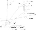
図1は,本実施形態にかかる鳥類退避装置および風力発電装置を説明するための全体図である。鳥類退避装置10は、所定の空間領域を継続的に撮影する撮像部11と、撮像部11により得られた画像から所定の空間領域に存在する鳥(鳥類)を検出する鳥類検出部12と、鳥類検出部12が鳥を検出した場合に、検出信号を出力する出力部13と、出力部13からの検出信号を受けて、ブレードの一部または全部にストロボ照明を行うストロボ照明部14と、から構成される。本実施形態では、ストロボ照明部14からの照明光を拡大または拡散するフレネルレンズ15が備えられている。 FIG. 1 is an overall view for explaining a bird evacuation device and a wind power generator according to the present embodiment. The
一般的なプロペラ型風力発電装置20は,地上に立設したタワー24と,そのタワー24に設置されたナセル23と,そのナセル23に対してロータヘッド22を介して自在に回転する複数のブレード21と,からなる。 A general propeller-type
風力発電装置20に接近して飛行する鳥が、撮像部11が撮影する領域に進入し、鳥類検出部12により検出されると、出力部13からの検出信号を受けて、ストロボ照明部14から、ブレード21の一部または全部にストロボ照明が行われる。ストロボ光が照射されることにより、鳥にはブレード21が瞬間的に静止して見える。従って、鳥は的確にブレード21を認識することができ、風力発電装置20にさらに接近して、風力発電装置20のブレード21に衝突するような事故を防ぐことができる。 When a bird flying close to the
撮像部11には、例えばCCD(Charge Coupled Device)撮像素子を備えたカメラ(CCDカメラ)が用いられる。CMOS(Complementary
Metal Oxide Semiconductor)撮像素子を備えたカメラを用いても良い。CCDカメラは、例えば毎秒30コマの頻度で対象領域を撮影する。For the
(Metal Oxide Semiconductor) A camera equipped with an image sensor may be used. The CCD camera images the target area at a frequency of 30 frames per second, for example.
鳥類検出部12の鳥類検出アルゴリズムには、例えば、粒子画像流速(Particle Image Velocimetry:PIV)手法やオプティカルフローの手法を用いることができる。PIV手法では、鳥を粒子と捉えて、撮像部11が撮影した画像内の粒子の動く様子から鳥を検出することができる。オプティカルフローの手法では、撮像部11が撮影した画像内の各位置座標における速度ベクトルを算出し、例えば、所定の基準値を超えた場合に鳥であると判断することができる。鳥の特徴を集積したデータベースを作成しておいて、画像内の対象物が、データベースの鳥に合致するか否かにより、鳥の検出を行うこともできる。 For the bird detection algorithm of the
ストロボ照明部14は電源(図示しない)と光源を備えており、電源から光源に電力が供給される。ストロボ照明部14の光源には、例えば発光ダイオードが用いられる。発光ダイオードは,単品でもよいし,リング状の集合体でもよい。リング状の集合体の場合は,発光ダイオードの配置を工夫することによって指向性を高めることができる。広い範囲を照明する場合は、光を広げるために,球面上に発光ダイオードを配設してもよいし、図1に示すように、ストロボ照明部14の前面にフレネルレンズ15を配置すればよい。 The
フレネルレンズ15を配置する場合は、通常のレンズよりも相対的に薄いレンズを用いることができるため、レンズの重さを軽くし、費用も安くできる。フレネルレンズ15は、フレネルレンズ15透過後の光の焦点距離が負の小さい値(例えば,−50mm程度)となるものを用いれば、ストロボ光を所定平面内で拡散させることができる。 When the
ストロボ光の発光周波数は、鳥の動体視力を考慮して、ブレード21が鳥の眼に瞬間的に静止して視認されるような周波数であればよい。動体視力は臨界融合周波数(Critical Flicker Frequency:CFF)を指標として考えることができ、人間のCFFは50Hz程度とされる。一般的な鳥の動体視力は人間の3倍から4倍と言われている。従って、約200Hz以下の周波数でストロボ光を発光すれば、ブレード21は鳥の眼に瞬間的に静止して視認される。鷲や鷹などの猛禽類はさらに動体視力がよいと言われているので、200Hzより高い周波数でも、猛禽類にはブレード21は断続的に静止して視認される。 The light emission frequency of the strobe light may be a frequency at which the
周波数を50Hzより大きく、200Hzより小さい値とすれば、人間にはブレード21が連続して見える。一方、鳥にはブレード21が断続的に静止して見えるようにでき、人間の視覚には影響を与えずに、鳥に対してブレード21を的確に認識させることが可能である。 If the frequency is set to a value larger than 50 Hz and smaller than 200 Hz, the
例えば、ブレード21の長さが50mで、ブレード21が1秒間に1回転しているとすると、ブレード21先端部の速さは、2*50*3.14=314m/secとなる。これに対し、100Hzのストロボ光を照射すると、約1.57mの軌跡のブレード21が断続的に視認されることになる。 For example, if the length of the
なお、夜間、霧が出ているとき、降雨時などで、撮像部11が撮影した画像をもとに鳥を検出できない場合は、適当な時間間隔でストロボ照明を行えばよい。例えば10分間隔で発光ダイオードのストロボ光をブレード21に照射することにより、経済性を大きく損なわずに、鳥にブレード21を的確に認識させ、風力発電装置20へのさらなる接近を防止することができる。 If a bird cannot be detected based on an image taken by the
図2は,ロータヘッドにストロボ照明部を設置した状態を説明するための側面図である。ストロボ照明部14はロータヘッド22に設置されており、ブレード21とともに回転しながら、出力部13からの鳥の検出信号に応じて、ブレード21の根元からブレード21の一部または全部にストロボ光を照射する。図2に示すように、ブレード21の数と同じ数のLEDストロボ(ストロボ照明部)14を設置することにより、ブレード21を的確にスロトボ照明することができ、鳥の視認性を高めることができる。 FIG. 2 is a side view for explaining a state in which the strobe illumination unit is installed on the rotor head. The
ストロボ照明は、ブレード21の先端から約1/3の範囲を照明することとしてもよい。ブレードに衝突した鳥の死骸をみると,鋭利な角度で切断されたものが少なからずあり,ブレード先端付近で衝突したことが想像される。よって,ブレード21先端付近をストロボ照明して、鳥にブレード21を的確に視認させれば、ブレード21への衝突事故を防ぐ効果を高めることができる。 The strobe illumination may illuminate a range of about 3 from the tip of the
ブレード21を正面から照明する場合は、ストロボ照明部14を例えばタワー24に設置してもよい。また、ストロボ照明部14をナセル23に設置してブレード21を後方から照明することもできる。 When the
複数の風力発電装置20により構成されるウィンドファームにおいては、ウィンドファームの外縁部に設置される風力発電装置20に衝突する事故が多いとの報告もあるため、そのような外縁部に位置する風力発電装置20のブレード21を特にストロボ照明することも効果的である。 In a wind farm composed of a plurality of
本発明は,鳥類の退避を促す鳥類退避装置と鳥類退避装置を備えた風力発電装置に利用することができる。 INDUSTRIAL APPLICABILITY The present invention can be used for a bird evacuation device that promotes the evacuation of birds and a wind turbine generator that includes the bird evacuation device.
10 …鳥類退避装置
11 …撮像部
12 …鳥類検出部
13 …出力部
14 …LEDストロボ(ストロボ照明部)
15 …フレネルレンズ
20 …風力発電装置
21 …ブレード
22 …ロータヘッド
23 …ナセル
24 …タワー
DESCRIPTION OF
DESCRIPTION OF
Claims (4)
Translated fromJapanese前記撮像部により得られた画像から前記所定の空間領域に存在する鳥類を検出する鳥類検出部と、
前記鳥類検出部が鳥類を検出した場合に、検出信号を出力する出力部と、
前記出力部からの検出信号を受けて、ブレードを有する回転体の該ブレードの一部または全部にストロボ照明を行うストロボ照明部と、
を備えることを特徴とする鳥類退避装置。An imaging unit that continuously captures a predetermined spatial region;
An avian detection unit that detects the birds present in the predetermined spatial region from the image obtained by the imaging unit;
An output unit that outputs a detection signal when the bird detection unit detects a bird;
A strobe illumination unit that receives a detection signal from the output unit and performs strobe illumination on part or all of the blade of the rotating body having the blade;
A bird evacuation device comprising:
当該風力発電装置の周囲に予め設定した所定の空間領域を継続的に撮影する撮像部と、
前記撮像部により得られた画像から前記所定の空間領域に存在する鳥類を検出する鳥類検出部と、
前記鳥類検出部が鳥類を検出した場合に、検出信号を出力する出力部と、
前記出力部からの検出信号を受けて、前記ブレードの一部または全部にストロボ照明を行うストロボ照明部と、
を備えることを特徴とする風力発電装置。A wind turbine generator comprising a tower erected on the ground, a nacelle fixed to the tower, and a plurality of blades fixed to the nacelle via a rotor head so as to be rotatable,
An imaging unit that continuously captures a predetermined space area set in advance around the wind turbine generator;
An avian detection unit that detects the birds present in the predetermined spatial region from the image obtained by the imaging unit;
An output unit that outputs a detection signal when the bird detection unit detects a bird;
In response to a detection signal from the output unit, a strobe illumination unit that performs strobe illumination on part or all of the blade;
A wind turbine generator comprising:
Priority Applications (1)
| Application Number | Priority Date | Filing Date | Title |
|---|---|---|---|
| JP2009093585AJP5207140B2 (en) | 2009-04-08 | 2009-04-08 | Bird escape device and wind power generator |
Applications Claiming Priority (1)
| Application Number | Priority Date | Filing Date | Title |
|---|---|---|---|
| JP2009093585AJP5207140B2 (en) | 2009-04-08 | 2009-04-08 | Bird escape device and wind power generator |
Publications (2)
| Publication Number | Publication Date |
|---|---|
| JP2010242655Atrue JP2010242655A (en) | 2010-10-28 |
| JP5207140B2 JP5207140B2 (en) | 2013-06-12 |
Family
ID=43095912
Family Applications (1)
| Application Number | Title | Priority Date | Filing Date |
|---|---|---|---|
| JP2009093585AExpired - Fee RelatedJP5207140B2 (en) | 2009-04-08 | 2009-04-08 | Bird escape device and wind power generator |
Country Status (1)
| Country | Link |
|---|---|
| JP (1) | JP5207140B2 (en) |
Citations (8)
| Publication number | Priority date | Publication date | Assignee | Title |
|---|---|---|---|---|
| JPH09266748A (en)* | 1996-03-29 | 1997-10-14 | Susumu Takegawa | Apparatus for repulsing fowls by parallel turning with wind force, rodlike magnetic flux scanning and reflecting flash |
| JPH11193774A (en)* | 1997-12-27 | 1999-07-21 | Koito Ind Ltd | Wind power generator and aviation obstacle light device used therefor |
| JP2002101805A (en)* | 2000-10-02 | 2002-04-09 | Bird Stopper:Kk | Apparatus for repelling bird from coming flying |
| JP2003533789A (en)* | 2000-05-09 | 2003-11-11 | アロイス・ヴォベン | Wind warning light device for wind power equipment |
| JP2003339301A (en)* | 2002-05-29 | 2003-12-02 | Noritz Corp | Apparatus for preventing bird and animal injury |
| JP2005531710A (en)* | 2002-06-07 | 2005-10-20 | アロイス・ヴォベン | Wind power generator |
| JP2006125266A (en)* | 2004-10-28 | 2006-05-18 | Tokyo Electric Power Co Inc:The | Wind turbine generator, wind turbine generator control method, and computer program |
| JP2006211917A (en)* | 2005-02-01 | 2006-08-17 | Matsushita Electric Works Ltd | Noxious animal-repulsing system |
- 2009
- 2009-04-08JPJP2009093585Apatent/JP5207140B2/ennot_activeExpired - Fee Related
Patent Citations (8)
| Publication number | Priority date | Publication date | Assignee | Title |
|---|---|---|---|---|
| JPH09266748A (en)* | 1996-03-29 | 1997-10-14 | Susumu Takegawa | Apparatus for repulsing fowls by parallel turning with wind force, rodlike magnetic flux scanning and reflecting flash |
| JPH11193774A (en)* | 1997-12-27 | 1999-07-21 | Koito Ind Ltd | Wind power generator and aviation obstacle light device used therefor |
| JP2003533789A (en)* | 2000-05-09 | 2003-11-11 | アロイス・ヴォベン | Wind warning light device for wind power equipment |
| JP2002101805A (en)* | 2000-10-02 | 2002-04-09 | Bird Stopper:Kk | Apparatus for repelling bird from coming flying |
| JP2003339301A (en)* | 2002-05-29 | 2003-12-02 | Noritz Corp | Apparatus for preventing bird and animal injury |
| JP2005531710A (en)* | 2002-06-07 | 2005-10-20 | アロイス・ヴォベン | Wind power generator |
| JP2006125266A (en)* | 2004-10-28 | 2006-05-18 | Tokyo Electric Power Co Inc:The | Wind turbine generator, wind turbine generator control method, and computer program |
| JP2006211917A (en)* | 2005-02-01 | 2006-08-17 | Matsushita Electric Works Ltd | Noxious animal-repulsing system |
Also Published As
| Publication number | Publication date |
|---|---|
| JP5207140B2 (en) | 2013-06-12 |
Similar Documents
| Publication | Publication Date | Title |
|---|---|---|
| AU2021202277B2 (en) | Avian detection systems and methods | |
| JP2010220542A (en) | Bird escape device and wind power generator | |
| JP2010239912A (en) | Bird escape device and wind power generator | |
| ES2790653T3 (en) | Detection and identification of birds or bats to mitigate the risk of wind turbines | |
| JP2011229453A (en) | Birds evacuating apparatus | |
| JP6729561B2 (en) | Light irradiation device and light irradiation system | |
| JP2010193768A (en) | Device for intimidating bird, and aerogenerator | |
| CN102150653B (en) | Mobile airport bird situation detection and directional bird repelling device | |
| US20130257641A1 (en) | Method and system for detecting animals in three dimensional space and for inducing an avoidance response in an animal | |
| DK2619452T3 (en) | Lights for offshore wind park | |
| JP2010106667A (en) | Blade structure and wind power generator | |
| WO2007038992A1 (en) | Method for regulating a wind energy installation | |
| CN107455361B (en) | A comprehensive bird repelling device with laser voice | |
| CN113484201B (en) | A method and device for detecting and measuring particle size of atmospheric cloud and fog fields | |
| JP3187091U (en) | Pest repelling device | |
| CN104982416A (en) | Intelligent video laser bird repelling device for day and night and using method of intelligent video laser bird repelling device | |
| JP4626266B2 (en) | Wind turbine generator, wind turbine generator control method, and computer program | |
| CN109300268A (en) | A method and device for intelligent adjustment of warning light based on image recognition | |
| JP2009203873A (en) | Flying object detection system, wind turbine generator, and computer program | |
| JP2024542348A (en) | High-intensity lighting system and method for using same | |
| KR20200034170A (en) | Apparatus for prevention of fur and feather | |
| CN117581851A (en) | A fan bird repelling device and method | |
| JP2010270623A (en) | Wind power generator | |
| JP5207140B2 (en) | Bird escape device and wind power generator | |
| CN108142408B (en) | Bird repelling system and method for wind farm and wind farm and offshore wind farm |
Legal Events
| Date | Code | Title | Description |
|---|---|---|---|
| A621 | Written request for application examination | Free format text:JAPANESE INTERMEDIATE CODE: A621 Effective date:20120403 | |
| A977 | Report on retrieval | Free format text:JAPANESE INTERMEDIATE CODE: A971007 Effective date:20130121 | |
| TRDD | Decision of grant or rejection written | ||
| A01 | Written decision to grant a patent or to grant a registration (utility model) | Free format text:JAPANESE INTERMEDIATE CODE: A01 Effective date:20130125 | |
| A61 | First payment of annual fees (during grant procedure) | Free format text:JAPANESE INTERMEDIATE CODE: A61 Effective date:20130207 | |
| FPAY | Renewal fee payment (event date is renewal date of database) | Free format text:PAYMENT UNTIL: 20160301 Year of fee payment:3 | |
| R150 | Certificate of patent or registration of utility model | Free format text:JAPANESE INTERMEDIATE CODE: R150 | |
| LAPS | Cancellation because of no payment of annual fees |