JP2010241427A - Charger/generator unit for hybrid electric vehicle - Google Patents
Charger/generator unit for hybrid electric vehicleDownload PDFInfo
- Publication number
- JP2010241427A JP2010241427AJP2010115555AJP2010115555AJP2010241427AJP 2010241427 AJP2010241427 AJP 2010241427AJP 2010115555 AJP2010115555 AJP 2010115555AJP 2010115555 AJP2010115555 AJP 2010115555AJP 2010241427 AJP2010241427 AJP 2010241427A
- Authority
- JP
- Japan
- Prior art keywords
- power
- hybrid electric
- electric vehicle
- hpu
- generator
- Prior art date
- Legal status (The legal status is an assumption and is not a legal conclusion. Google has not performed a legal analysis and makes no representation as to the accuracy of the status listed.)
- Pending
Links
Images


Classifications
- B—PERFORMING OPERATIONS; TRANSPORTING
- B60—VEHICLES IN GENERAL
- B60K—ARRANGEMENT OR MOUNTING OF PROPULSION UNITS OR OF TRANSMISSIONS IN VEHICLES; ARRANGEMENT OR MOUNTING OF PLURAL DIVERSE PRIME-MOVERS IN VEHICLES; AUXILIARY DRIVES FOR VEHICLES; INSTRUMENTATION OR DASHBOARDS FOR VEHICLES; ARRANGEMENTS IN CONNECTION WITH COOLING, AIR INTAKE, GAS EXHAUST OR FUEL SUPPLY OF PROPULSION UNITS IN VEHICLES
- B60K6/00—Arrangement or mounting of plural diverse prime-movers for mutual or common propulsion, e.g. hybrid propulsion systems comprising electric motors and internal combustion engines
- B60K6/20—Arrangement or mounting of plural diverse prime-movers for mutual or common propulsion, e.g. hybrid propulsion systems comprising electric motors and internal combustion engines the prime-movers consisting of electric motors and internal combustion engines, e.g. HEVs
- B60K6/42—Arrangement or mounting of plural diverse prime-movers for mutual or common propulsion, e.g. hybrid propulsion systems comprising electric motors and internal combustion engines the prime-movers consisting of electric motors and internal combustion engines, e.g. HEVs characterised by the architecture of the hybrid electric vehicle
- B60K6/48—Parallel type
- B—PERFORMING OPERATIONS; TRANSPORTING
- B60—VEHICLES IN GENERAL
- B60L—PROPULSION OF ELECTRICALLY-PROPELLED VEHICLES; SUPPLYING ELECTRIC POWER FOR AUXILIARY EQUIPMENT OF ELECTRICALLY-PROPELLED VEHICLES; ELECTRODYNAMIC BRAKE SYSTEMS FOR VEHICLES IN GENERAL; MAGNETIC SUSPENSION OR LEVITATION FOR VEHICLES; MONITORING OPERATING VARIABLES OF ELECTRICALLY-PROPELLED VEHICLES; ELECTRIC SAFETY DEVICES FOR ELECTRICALLY-PROPELLED VEHICLES
- B60L1/00—Supplying electric power to auxiliary equipment of vehicles
- B60L1/003—Supplying electric power to auxiliary equipment of vehicles to auxiliary motors, e.g. for pumps, compressors
- B—PERFORMING OPERATIONS; TRANSPORTING
- B60—VEHICLES IN GENERAL
- B60L—PROPULSION OF ELECTRICALLY-PROPELLED VEHICLES; SUPPLYING ELECTRIC POWER FOR AUXILIARY EQUIPMENT OF ELECTRICALLY-PROPELLED VEHICLES; ELECTRODYNAMIC BRAKE SYSTEMS FOR VEHICLES IN GENERAL; MAGNETIC SUSPENSION OR LEVITATION FOR VEHICLES; MONITORING OPERATING VARIABLES OF ELECTRICALLY-PROPELLED VEHICLES; ELECTRIC SAFETY DEVICES FOR ELECTRICALLY-PROPELLED VEHICLES
- B60L1/00—Supplying electric power to auxiliary equipment of vehicles
- B60L1/006—Supplying electric power to auxiliary equipment of vehicles to power outlets
- B—PERFORMING OPERATIONS; TRANSPORTING
- B60—VEHICLES IN GENERAL
- B60L—PROPULSION OF ELECTRICALLY-PROPELLED VEHICLES; SUPPLYING ELECTRIC POWER FOR AUXILIARY EQUIPMENT OF ELECTRICALLY-PROPELLED VEHICLES; ELECTRODYNAMIC BRAKE SYSTEMS FOR VEHICLES IN GENERAL; MAGNETIC SUSPENSION OR LEVITATION FOR VEHICLES; MONITORING OPERATING VARIABLES OF ELECTRICALLY-PROPELLED VEHICLES; ELECTRIC SAFETY DEVICES FOR ELECTRICALLY-PROPELLED VEHICLES
- B60L15/00—Methods, circuits, or devices for controlling the traction-motor speed of electrically-propelled vehicles
- B60L15/02—Methods, circuits, or devices for controlling the traction-motor speed of electrically-propelled vehicles characterised by the form of the current used in the control circuit
- B60L15/025—Methods, circuits, or devices for controlling the traction-motor speed of electrically-propelled vehicles characterised by the form of the current used in the control circuit using field orientation; Vector control; Direct Torque Control [DTC]
- B—PERFORMING OPERATIONS; TRANSPORTING
- B60—VEHICLES IN GENERAL
- B60L—PROPULSION OF ELECTRICALLY-PROPELLED VEHICLES; SUPPLYING ELECTRIC POWER FOR AUXILIARY EQUIPMENT OF ELECTRICALLY-PROPELLED VEHICLES; ELECTRODYNAMIC BRAKE SYSTEMS FOR VEHICLES IN GENERAL; MAGNETIC SUSPENSION OR LEVITATION FOR VEHICLES; MONITORING OPERATING VARIABLES OF ELECTRICALLY-PROPELLED VEHICLES; ELECTRIC SAFETY DEVICES FOR ELECTRICALLY-PROPELLED VEHICLES
- B60L50/00—Electric propulsion with power supplied within the vehicle
- B60L50/10—Electric propulsion with power supplied within the vehicle using propulsion power supplied by engine-driven generators, e.g. generators driven by combustion engines
- B60L50/16—Electric propulsion with power supplied within the vehicle using propulsion power supplied by engine-driven generators, e.g. generators driven by combustion engines with provision for separate direct mechanical propulsion
- B—PERFORMING OPERATIONS; TRANSPORTING
- B60—VEHICLES IN GENERAL
- B60L—PROPULSION OF ELECTRICALLY-PROPELLED VEHICLES; SUPPLYING ELECTRIC POWER FOR AUXILIARY EQUIPMENT OF ELECTRICALLY-PROPELLED VEHICLES; ELECTRODYNAMIC BRAKE SYSTEMS FOR VEHICLES IN GENERAL; MAGNETIC SUSPENSION OR LEVITATION FOR VEHICLES; MONITORING OPERATING VARIABLES OF ELECTRICALLY-PROPELLED VEHICLES; ELECTRIC SAFETY DEVICES FOR ELECTRICALLY-PROPELLED VEHICLES
- B60L50/00—Electric propulsion with power supplied within the vehicle
- B60L50/50—Electric propulsion with power supplied within the vehicle using propulsion power supplied by batteries or fuel cells
- B60L50/60—Electric propulsion with power supplied within the vehicle using propulsion power supplied by batteries or fuel cells using power supplied by batteries
- B60L50/61—Electric propulsion with power supplied within the vehicle using propulsion power supplied by batteries or fuel cells using power supplied by batteries by batteries charged by engine-driven generators, e.g. series hybrid electric vehicles
- B—PERFORMING OPERATIONS; TRANSPORTING
- B60—VEHICLES IN GENERAL
- B60L—PROPULSION OF ELECTRICALLY-PROPELLED VEHICLES; SUPPLYING ELECTRIC POWER FOR AUXILIARY EQUIPMENT OF ELECTRICALLY-PROPELLED VEHICLES; ELECTRODYNAMIC BRAKE SYSTEMS FOR VEHICLES IN GENERAL; MAGNETIC SUSPENSION OR LEVITATION FOR VEHICLES; MONITORING OPERATING VARIABLES OF ELECTRICALLY-PROPELLED VEHICLES; ELECTRIC SAFETY DEVICES FOR ELECTRICALLY-PROPELLED VEHICLES
- B60L53/00—Methods of charging batteries, specially adapted for electric vehicles; Charging stations or on-board charging equipment therefor; Exchange of energy storage elements in electric vehicles
- B60L53/10—Methods of charging batteries, specially adapted for electric vehicles; Charging stations or on-board charging equipment therefor; Exchange of energy storage elements in electric vehicles characterised by the energy transfer between the charging station and the vehicle
- B60L53/14—Conductive energy transfer
- B—PERFORMING OPERATIONS; TRANSPORTING
- B60—VEHICLES IN GENERAL
- B60L—PROPULSION OF ELECTRICALLY-PROPELLED VEHICLES; SUPPLYING ELECTRIC POWER FOR AUXILIARY EQUIPMENT OF ELECTRICALLY-PROPELLED VEHICLES; ELECTRODYNAMIC BRAKE SYSTEMS FOR VEHICLES IN GENERAL; MAGNETIC SUSPENSION OR LEVITATION FOR VEHICLES; MONITORING OPERATING VARIABLES OF ELECTRICALLY-PROPELLED VEHICLES; ELECTRIC SAFETY DEVICES FOR ELECTRICALLY-PROPELLED VEHICLES
- B60L53/00—Methods of charging batteries, specially adapted for electric vehicles; Charging stations or on-board charging equipment therefor; Exchange of energy storage elements in electric vehicles
- B60L53/20—Methods of charging batteries, specially adapted for electric vehicles; Charging stations or on-board charging equipment therefor; Exchange of energy storage elements in electric vehicles characterised by converters located in the vehicle
- B60L53/24—Using the vehicle's propulsion converter for charging
- B—PERFORMING OPERATIONS; TRANSPORTING
- B60—VEHICLES IN GENERAL
- B60L—PROPULSION OF ELECTRICALLY-PROPELLED VEHICLES; SUPPLYING ELECTRIC POWER FOR AUXILIARY EQUIPMENT OF ELECTRICALLY-PROPELLED VEHICLES; ELECTRODYNAMIC BRAKE SYSTEMS FOR VEHICLES IN GENERAL; MAGNETIC SUSPENSION OR LEVITATION FOR VEHICLES; MONITORING OPERATING VARIABLES OF ELECTRICALLY-PROPELLED VEHICLES; ELECTRIC SAFETY DEVICES FOR ELECTRICALLY-PROPELLED VEHICLES
- B60L53/00—Methods of charging batteries, specially adapted for electric vehicles; Charging stations or on-board charging equipment therefor; Exchange of energy storage elements in electric vehicles
- B60L53/30—Constructional details of charging stations
- B60L53/305—Communication interfaces
- H—ELECTRICITY
- H02—GENERATION; CONVERSION OR DISTRIBUTION OF ELECTRIC POWER
- H02J—CIRCUIT ARRANGEMENTS OR SYSTEMS FOR SUPPLYING OR DISTRIBUTING ELECTRIC POWER; SYSTEMS FOR STORING ELECTRIC ENERGY
- H02J7/00—Circuit arrangements for charging or depolarising batteries or for supplying loads from batteries
- H02J7/14—Circuit arrangements for charging or depolarising batteries or for supplying loads from batteries for charging batteries from dynamo-electric generators driven at varying speed, e.g. on vehicle
- H02J7/1415—Circuit arrangements for charging or depolarising batteries or for supplying loads from batteries for charging batteries from dynamo-electric generators driven at varying speed, e.g. on vehicle with a generator driven by a prime mover other than the motor of a vehicle
- B—PERFORMING OPERATIONS; TRANSPORTING
- B60—VEHICLES IN GENERAL
- B60L—PROPULSION OF ELECTRICALLY-PROPELLED VEHICLES; SUPPLYING ELECTRIC POWER FOR AUXILIARY EQUIPMENT OF ELECTRICALLY-PROPELLED VEHICLES; ELECTRODYNAMIC BRAKE SYSTEMS FOR VEHICLES IN GENERAL; MAGNETIC SUSPENSION OR LEVITATION FOR VEHICLES; MONITORING OPERATING VARIABLES OF ELECTRICALLY-PROPELLED VEHICLES; ELECTRIC SAFETY DEVICES FOR ELECTRICALLY-PROPELLED VEHICLES
- B60L2210/00—Converter types
- B60L2210/20—AC to AC converters
- B—PERFORMING OPERATIONS; TRANSPORTING
- B60—VEHICLES IN GENERAL
- B60L—PROPULSION OF ELECTRICALLY-PROPELLED VEHICLES; SUPPLYING ELECTRIC POWER FOR AUXILIARY EQUIPMENT OF ELECTRICALLY-PROPELLED VEHICLES; ELECTRODYNAMIC BRAKE SYSTEMS FOR VEHICLES IN GENERAL; MAGNETIC SUSPENSION OR LEVITATION FOR VEHICLES; MONITORING OPERATING VARIABLES OF ELECTRICALLY-PROPELLED VEHICLES; ELECTRIC SAFETY DEVICES FOR ELECTRICALLY-PROPELLED VEHICLES
- B60L2220/00—Electrical machine types; Structures or applications thereof
- B60L2220/50—Structural details of electrical machines
- B60L2220/54—Windings for different functions
- Y—GENERAL TAGGING OF NEW TECHNOLOGICAL DEVELOPMENTS; GENERAL TAGGING OF CROSS-SECTIONAL TECHNOLOGIES SPANNING OVER SEVERAL SECTIONS OF THE IPC; TECHNICAL SUBJECTS COVERED BY FORMER USPC CROSS-REFERENCE ART COLLECTIONS [XRACs] AND DIGESTS
- Y02—TECHNOLOGIES OR APPLICATIONS FOR MITIGATION OR ADAPTATION AGAINST CLIMATE CHANGE
- Y02T—CLIMATE CHANGE MITIGATION TECHNOLOGIES RELATED TO TRANSPORTATION
- Y02T10/00—Road transport of goods or passengers
- Y02T10/60—Other road transportation technologies with climate change mitigation effect
- Y02T10/62—Hybrid vehicles
- Y—GENERAL TAGGING OF NEW TECHNOLOGICAL DEVELOPMENTS; GENERAL TAGGING OF CROSS-SECTIONAL TECHNOLOGIES SPANNING OVER SEVERAL SECTIONS OF THE IPC; TECHNICAL SUBJECTS COVERED BY FORMER USPC CROSS-REFERENCE ART COLLECTIONS [XRACs] AND DIGESTS
- Y02—TECHNOLOGIES OR APPLICATIONS FOR MITIGATION OR ADAPTATION AGAINST CLIMATE CHANGE
- Y02T—CLIMATE CHANGE MITIGATION TECHNOLOGIES RELATED TO TRANSPORTATION
- Y02T10/00—Road transport of goods or passengers
- Y02T10/60—Other road transportation technologies with climate change mitigation effect
- Y02T10/64—Electric machine technologies in electromobility
- Y—GENERAL TAGGING OF NEW TECHNOLOGICAL DEVELOPMENTS; GENERAL TAGGING OF CROSS-SECTIONAL TECHNOLOGIES SPANNING OVER SEVERAL SECTIONS OF THE IPC; TECHNICAL SUBJECTS COVERED BY FORMER USPC CROSS-REFERENCE ART COLLECTIONS [XRACs] AND DIGESTS
- Y02—TECHNOLOGIES OR APPLICATIONS FOR MITIGATION OR ADAPTATION AGAINST CLIMATE CHANGE
- Y02T—CLIMATE CHANGE MITIGATION TECHNOLOGIES RELATED TO TRANSPORTATION
- Y02T10/00—Road transport of goods or passengers
- Y02T10/60—Other road transportation technologies with climate change mitigation effect
- Y02T10/70—Energy storage systems for electromobility, e.g. batteries
- Y—GENERAL TAGGING OF NEW TECHNOLOGICAL DEVELOPMENTS; GENERAL TAGGING OF CROSS-SECTIONAL TECHNOLOGIES SPANNING OVER SEVERAL SECTIONS OF THE IPC; TECHNICAL SUBJECTS COVERED BY FORMER USPC CROSS-REFERENCE ART COLLECTIONS [XRACs] AND DIGESTS
- Y02—TECHNOLOGIES OR APPLICATIONS FOR MITIGATION OR ADAPTATION AGAINST CLIMATE CHANGE
- Y02T—CLIMATE CHANGE MITIGATION TECHNOLOGIES RELATED TO TRANSPORTATION
- Y02T10/00—Road transport of goods or passengers
- Y02T10/60—Other road transportation technologies with climate change mitigation effect
- Y02T10/7072—Electromobility specific charging systems or methods for batteries, ultracapacitors, supercapacitors or double-layer capacitors
- Y—GENERAL TAGGING OF NEW TECHNOLOGICAL DEVELOPMENTS; GENERAL TAGGING OF CROSS-SECTIONAL TECHNOLOGIES SPANNING OVER SEVERAL SECTIONS OF THE IPC; TECHNICAL SUBJECTS COVERED BY FORMER USPC CROSS-REFERENCE ART COLLECTIONS [XRACs] AND DIGESTS
- Y02—TECHNOLOGIES OR APPLICATIONS FOR MITIGATION OR ADAPTATION AGAINST CLIMATE CHANGE
- Y02T—CLIMATE CHANGE MITIGATION TECHNOLOGIES RELATED TO TRANSPORTATION
- Y02T10/00—Road transport of goods or passengers
- Y02T10/60—Other road transportation technologies with climate change mitigation effect
- Y02T10/72—Electric energy management in electromobility
- Y—GENERAL TAGGING OF NEW TECHNOLOGICAL DEVELOPMENTS; GENERAL TAGGING OF CROSS-SECTIONAL TECHNOLOGIES SPANNING OVER SEVERAL SECTIONS OF THE IPC; TECHNICAL SUBJECTS COVERED BY FORMER USPC CROSS-REFERENCE ART COLLECTIONS [XRACs] AND DIGESTS
- Y02—TECHNOLOGIES OR APPLICATIONS FOR MITIGATION OR ADAPTATION AGAINST CLIMATE CHANGE
- Y02T—CLIMATE CHANGE MITIGATION TECHNOLOGIES RELATED TO TRANSPORTATION
- Y02T90/00—Enabling technologies or technologies with a potential or indirect contribution to GHG emissions mitigation
- Y02T90/10—Technologies relating to charging of electric vehicles
- Y02T90/12—Electric charging stations
- Y—GENERAL TAGGING OF NEW TECHNOLOGICAL DEVELOPMENTS; GENERAL TAGGING OF CROSS-SECTIONAL TECHNOLOGIES SPANNING OVER SEVERAL SECTIONS OF THE IPC; TECHNICAL SUBJECTS COVERED BY FORMER USPC CROSS-REFERENCE ART COLLECTIONS [XRACs] AND DIGESTS
- Y02—TECHNOLOGIES OR APPLICATIONS FOR MITIGATION OR ADAPTATION AGAINST CLIMATE CHANGE
- Y02T—CLIMATE CHANGE MITIGATION TECHNOLOGIES RELATED TO TRANSPORTATION
- Y02T90/00—Enabling technologies or technologies with a potential or indirect contribution to GHG emissions mitigation
- Y02T90/10—Technologies relating to charging of electric vehicles
- Y02T90/14—Plug-in electric vehicles
- Y—GENERAL TAGGING OF NEW TECHNOLOGICAL DEVELOPMENTS; GENERAL TAGGING OF CROSS-SECTIONAL TECHNOLOGIES SPANNING OVER SEVERAL SECTIONS OF THE IPC; TECHNICAL SUBJECTS COVERED BY FORMER USPC CROSS-REFERENCE ART COLLECTIONS [XRACs] AND DIGESTS
- Y02—TECHNOLOGIES OR APPLICATIONS FOR MITIGATION OR ADAPTATION AGAINST CLIMATE CHANGE
- Y02T—CLIMATE CHANGE MITIGATION TECHNOLOGIES RELATED TO TRANSPORTATION
- Y02T90/00—Enabling technologies or technologies with a potential or indirect contribution to GHG emissions mitigation
- Y02T90/10—Technologies relating to charging of electric vehicles
- Y02T90/16—Information or communication technologies improving the operation of electric vehicles
- Y—GENERAL TAGGING OF NEW TECHNOLOGICAL DEVELOPMENTS; GENERAL TAGGING OF CROSS-SECTIONAL TECHNOLOGIES SPANNING OVER SEVERAL SECTIONS OF THE IPC; TECHNICAL SUBJECTS COVERED BY FORMER USPC CROSS-REFERENCE ART COLLECTIONS [XRACs] AND DIGESTS
- Y10—TECHNICAL SUBJECTS COVERED BY FORMER USPC
- Y10S—TECHNICAL SUBJECTS COVERED BY FORMER USPC CROSS-REFERENCE ART COLLECTIONS [XRACs] AND DIGESTS
- Y10S903/00—Hybrid electric vehicles, HEVS
- Y10S903/902—Prime movers comprising electrical and internal combustion motors
- Y10S903/903—Prime movers comprising electrical and internal combustion motors having energy storing means, e.g. battery, capacitor
- Y10S903/904—Component specially adapted for hev
- Y10S903/906—Motor or generator
Landscapes
- Engineering & Computer Science (AREA)
- Power Engineering (AREA)
- Mechanical Engineering (AREA)
- Transportation (AREA)
- Life Sciences & Earth Sciences (AREA)
- Combustion & Propulsion (AREA)
- Chemical & Material Sciences (AREA)
- Sustainable Development (AREA)
- Sustainable Energy (AREA)
- Electric Propulsion And Braking For Vehicles (AREA)
- Hybrid Electric Vehicles (AREA)
- Charge And Discharge Circuits For Batteries Or The Like (AREA)
- Secondary Cells (AREA)
Abstract
Description
Translated fromJapanese本発明は、車両バッテリー用の汎用畜電器として機能すると共に、電動工具の様な外部電気機器を作動させるための発電機として機能する、ハイブリッド電気自動車(hybrid electric vehicle略してHEV)用のホーム・パワー・ユニット(home power unit略してHPU)に関する。 The present invention provides a home for a hybrid electric vehicle (HEV for short) that functions as a general-purpose livestock battery for a vehicle battery and also functions as a generator for operating an external electric device such as a power tool. It relates to the power unit (HPU for short).
化石燃料の消費量を削減する必要性、そして内燃機関を動力源とする自動車などの車両の排出物を削減する必要性は、良く知られている。この様な要求を満足するために、車両の動力源を電気モーターとする取組みが行われている。しかしながら、電気自動車においては、バッテリーを充電するのにかなりの時間を費やしても、走行距離及び出力が、限られている。これに代る解決策の一つは、内燃機関と電動モーターの両方を一つの車両に組込むことである。その様な車両が一般に、ハイブリッド電気自動車(HEV)と呼ばれている。例えば、米国特許5,343,970号に概略が開示されている。 The need to reduce fossil fuel consumption and the need to reduce emissions from vehicles such as automobiles powered by internal combustion engines is well known. In order to satisfy such requirements, efforts are being made to use an electric motor as the power source of the vehicle. However, in an electric vehicle, even if it takes a considerable time to charge the battery, the mileage and output are limited. One alternative solution is to incorporate both the internal combustion engine and the electric motor into a single vehicle. Such vehicles are commonly referred to as hybrid electric vehicles (HEV). For example, an outline is disclosed in US Pat. No. 5,343,970.
HEVについては、各種の形態のものが開示されてきた。多くのHEVの特許は、電気モーターの動作と内燃機関の動作との間を車両のドライバーが選択するのが必要であるシステムを開示している。それとは別に、電気モーターが一組の車輪を駆動し、内燃機関が別の組の車輪を駆動するものも、ある。 Various forms of HEV have been disclosed. Many HEV patents disclose systems that require a vehicle driver to choose between the operation of an electric motor and the operation of an internal combustion engine. Alternatively, an electric motor drives one set of wheels and an internal combustion engine drives another set of wheels.
他の形態も開発されてきた。シリーズ・ハイブリッド電気自動車(series hybrid electric vehicle略してSHEV)は、発電機を駆動するエンジン(最も一般的には内燃機関)を持つ車両である。そして、発電機が、バッテリー及び車両の駆動輪に接続されたモーターに電気を供給する。エンジンと駆動輪との間に機械的な結合関係はない。パラレル・ハイブリッド電気自動車(parallel hybrid electric vehicle略してPHEV)は、車輪を駆動するトルクを発生するために組合わせられたエンジン(最も一般的には内燃機関)、バッテリー及び電気モーターを持つ、車両である。 Other forms have also been developed. A series hybrid electric vehicle (SHEV for short) is a vehicle having an engine (most commonly an internal combustion engine) that drives a generator. The generator then supplies electricity to the motor connected to the battery and the drive wheels of the vehicle. There is no mechanical coupling between the engine and the drive wheels. A parallel hybrid electric vehicle (PHEV for short) is a vehicle that has an engine (most commonly an internal combustion engine), a battery and an electric motor combined to generate torque to drive the wheels. is there.
パラレル/シリーズ・ハイブリッド電気自動車(parallel/series hybrid electric vehicle略してPSHEV)は、PHEVとSHEV両方の特性を持つ。PSHEVは、トルク・スプリット形の駆動系構成として、知られている。ここで、エンジンのトルク出力は、一部が駆動輪へ、一部が発電機に、与えられる。この構成においては、トルク出力が、いずれかの発生源又は両方から同時に来ることもあり得る。この構成においては、車両の制動システムが、バッテリーへの電荷を発生するため発電機を駆動するトルクを供給することが出来る。 Parallel / series hybrid electric vehicles (PSHEV for short) have both PHEV and SHEV characteristics. PSHEV is known as a torque split type drive system configuration. Here, part of the torque output of the engine is given to the drive wheels and partly to the generator. In this configuration, the torque output can come from either source or both simultaneously. In this configuration, the vehicle braking system can supply torque that drives the generator to generate charge to the battery.
HEVの開発が進むにつれて、新たな課題が現れると共に、新たな用途も開発されている。全てのHEVに付随する大きな課題の一つは、車両を発進させ動作させるのに充分なバッテリー充電量を確保することである。全てのバッテリーは、使用又は時間経過と共に、充電量を喪失する。一般に、HEVのバッテリーは、車両の内燃機関の発電機により充電される。しかしながら、異常状態や緊急時には、外部からのバッテリーの充電が必要となる場合がある。 As HEV development progresses, new challenges emerge and new uses are being developed. One of the major challenges associated with all HEVs is ensuring sufficient battery charge to start and operate the vehicle. All batteries lose their charge over time of use or over time. Generally, the HEV battery is charged by a generator of an internal combustion engine of a vehicle. However, in an abnormal state or emergency, it may be necessary to charge the battery from the outside.
HEVの用途には、そのバッテリー及び発電機を、電動工具の様な電気機器を動作させるための電源として、利用することが、考えられる。補助電源としてのこの種の車両の使用は、一般的な内燃機関車両においては周知である。具体的には、電気機器の電源として内燃機関の構成部分を利用する多くの特許が、発行されてきた。例えば、米国特許3,824,404号、米国特許3,953,740号、米国特許4,074,145号及び米国特許5,066,866号が、電気機器の電源として交流電圧を発生するために車両のオルタネーターを利用する各種の方法を開示している。しかしながら、HEVはオルタネーターを必要としないので、これらの特許はHEVには適用されない。HEVは既にそのバッテリー内に使用可能な電力を持つと共に、車載発電機を用いて補助電力を発生することが出来る。しかしながら、電気機器による外部使用のためには、HEVの電力が変換される必要がある。 For HEV applications, it is conceivable to use the battery and generator as a power source for operating electric equipment such as electric tools. The use of this type of vehicle as an auxiliary power source is well known in general internal combustion engine vehicles. Specifically, many patents have been issued that utilize components of an internal combustion engine as a power source for electrical equipment. For example, U.S. Pat. No. 3,824,404, U.S. Pat. No. 3,953,740, U.S. Pat. No. 4,074,145, and U.S. Pat. However, these patents do not apply to HEV because HEV does not require an alternator. The HEV already has power available in its battery and can generate auxiliary power using an onboard generator. However, for external use by electrical equipment, HEV power needs to be converted.
HEV用充電システムを、車両の電源システムが補助電力用途のために結線され得るものとする、装置、システム及び方法を提供することが、有利であり、経済的であり、そして効率的である。 It would be advantageous, economical, and efficient to provide an apparatus, system, and method that would allow a HEV charging system to be wired for an auxiliary power application.
本発明は、HEVのバッテリーを充電するともに、外部電気機器を動作させるための発電機としてHEVを利用する、方法、システム及び装置を提供するものである。この装置は、ホーム・パワー・ユニット(home power unit略してHPU)と呼ばれ、上記2つの機能を一つの装置又はシステムに組込むものである。これは、本発明を効率的かつ簡便に使用する。 The present invention provides a method, system and apparatus for charging an HEV battery and using the HEV as a generator for operating an external electrical device. This device is called a home power unit (HPU for short) and incorporates the above two functions into one device or system. This uses the present invention efficiently and conveniently.
HPUは、発電機として、緊急時又は異常状態において、使用者がHEVのバッテリーを充電するのを可能とする。一般に、バッテリーは、エンジンと組合わせられた車載発電機の作動により、充電される。車載の高電圧バッテリーの充電量が完全に消失した場合には、エンジンは始動不能となることになる。それで、HEVのバッテリーを充電するための方法を持つことが、必要である。本発明は、その様な方法を提供するものである。 HPU, as a generator, allows users to charge HEV batteries in emergency or abnormal situations. Generally, the battery is charged by the operation of an on-vehicle generator combined with the engine. When the charge amount of the on-vehicle high voltage battery is completely lost, the engine cannot be started. So it is necessary to have a way to charge HEV batteries. The present invention provides such a method.
HPUはまた、外部電気機器を作動させるために、車両の電力を引き出すのを可能とする、発電機として、機能する。HPUは、HEVの発電機、そして、ある程度はそのバッテリーから、電力を引き出す。HPUは、この電力を、電動工具の様な外部電気機器に使用可能な形態へと変換する。 The HPU also functions as a generator that allows the vehicle's power to be drawn to operate external electrical equipment. HPU draws power from HEV generators and, to some extent, their batteries. HPU converts this power into a form that can be used for external electrical equipment such as power tools.
両方のモードにおいてHPUは、HEVのバッテリーを充電するために外部電源の交流電力を直流電力に変換するため(充電機能)又は、車載直流電力を交流電力へ変換する変換機器として機能するため(発電機能)の、変換機器として機能する。両方のモードにおいて、HPUはまた、ある目標電圧から別の電圧へ(つまり、低電圧の110Vから高電圧の300Vへ、又はその逆に)変換することが可能である。最も単純な形態において、HPU装置は、変圧器電圧を変換する変換器、交流を直流へ変換するインバーター手段、交流を直流へ変換する整流手段、HEVと外部の電気負荷又は電源との接続手段、及び、充電機能と発電機能との間で動作を変更する切替手段、を有する。この装置は、外部負荷又はサービスに対して、変圧器との接続手段を介して、接続されるのが一般的である。そして、HPUは、HEVの高電圧直流バス及び、システム制御器、具体的にはバッテリー電子制御ユニットに、接続される。HPU用切替機器は、インストルメント・パネル上の二位置のモーメンタリー・スイッチ、インストルメント・パネルに取付けられたスクリーン上の表示部のメニュー選択部又はHPUに取付けられた二位置スイッチ、から構成することが出来る。 In both modes, the HPU converts AC power from an external power source into DC power to charge the HEV battery (charging function), or functions as a converter that converts in-vehicle DC power to AC power (power generation) Function) as a conversion device. In both modes, the HPU can also convert from one target voltage to another (ie, from a low voltage of 110V to a high voltage of 300V or vice versa). In the simplest form, the HPU device is a converter that converts a transformer voltage, an inverter means that converts alternating current to direct current, a rectifying means that converts alternating current to direct current, a means for connecting HEV to an external electrical load or power source, And switching means for changing the operation between the charging function and the power generation function. This device is generally connected to an external load or service via connection means with a transformer. The HPU is connected to an HEV high voltage DC bus and a system controller, specifically a battery electronic control unit. HPU switching equipment shall consist of a two-position momentary switch on the instrument panel, a menu selection part on the display on the screen attached to the instrument panel, or a two-position switch attached to the HPU. I can do it.
別の実施形態においては、HPUは、HEVの構成部品に直接組込まれる。この態様においては、重複した構成部品が排除される。特に、第1の別実施形態において、HPUのインバーター手段は既に車両内、具体的には主インバーター(traction inverter)の中にある。電源を車両機能(モーターへ行くもの)からHPU機能(発電機として動作し、フィルターへ進むもの)へ切替えるために、主インバーターとモーターとの間に、接触器が組込まれる。 In another embodiment, the HPU is integrated directly into the HEV components. In this aspect, duplicate components are eliminated. In particular, in a first alternative embodiment, the HPU inverter means are already in the vehicle, specifically in the main traction inverter. A contactor is incorporated between the main inverter and the motor to switch the power supply from the vehicle function (going to the motor) to the HPU function (operating as a generator and going to the filter).
第1の別実施形態において、HEV構成部品はまた、重複部品を排除するために、別のHPUユニットを組込むのとは対照的な構成とされる。この第2の代替実施形態において、変圧器とは対照的に、DC-DC変換器が用いられる。そして、インバーター/整流器手段は、DC-DC変換器が適切な電流変更を行なった後で、機能する。 In a first alternative embodiment, the HEV component is also configured in contrast to incorporating another HPU unit to eliminate duplicate parts. In this second alternative embodiment, in contrast to a transformer, a DC-DC converter is used. The inverter / rectifier means then functions after the DC-DC converter has made the appropriate current change.
本発明によれば、HEV用充電システムを、車両の電源システムが補助電力用途のために結線され得るものとすることが出来る。 According to the present invention, the charging system for HEV can be configured such that the power supply system of the vehicle can be connected for auxiliary power use.
以下、本発明の実施形態を図面に基づいて詳細に説明する。 Hereinafter, embodiments of the present invention will be described in detail with reference to the drawings.
本発明は、車両のバッテリーを緊急時に充電すると共に、蓄電池を用いて車両が外部電気機器を駆動するのを可能とするための、一体の装置又はシステムを提供するものである。本発明は、充電機能に加えて、ある程度外部電気機器を動作させるために、車両の発電機とバッテリーを使用するのを可能とするものである。本発明は、ホーム・パワー・ユニット(HPU)と呼ばれるものである。最も単純な形態において、HPUは、交流から直流へ又は直流から交流への、そしてある電圧から他の電圧への(例えば、110Vから300Vへ又は300Vから110Vへ)、電気的変換を実行する、別個の構成部品である。 The present invention provides an integrated device or system for charging a vehicle battery in an emergency and allowing the vehicle to drive an external electrical device using a storage battery. In addition to the charging function, the present invention enables the use of a vehicle generator and battery to operate external electrical equipment to some extent. The present invention is called a home power unit (HPU). In its simplest form, the HPU performs electrical conversion from AC to DC or from DC to AC and from one voltage to another (e.g., 110V to 300V or 300V to 110V). It is a separate component.
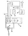
図1は、パラレル/シリーズ(トルク・スプリット形)ハイブリッド電気自動車の構成を示している。この車両の基本構成には、ワンウェイ・クラッチ36を介して遊星歯車26に接続されたエンジン20が含まれる。遊星歯車26は、エンジン20の出力を、エンジン20から発電機/モーター24への直列経路、及び、エンジン20から駆動輪34への並列経路へと、分離する。エンジン速度は、並列経路を介しての機械的結合を維持しながら、直列経路への分離度合を変更することにより、制御され得る。発電機/モーター24は、ジェネレーター・ブレーカー45に接続されている。発電機/モーター24は、バッテリー28に接続されて、バッテリー28を充電することが可能である。電気モーター30は、第2の歯車セット32を介して並列経路上でエンジンを補助する。このモーターはまた、直列経路から直接エネルギーを使用する場合もある。本質的には発電機/モーター24が発生する電力を引出し、バッテリー28の化学的エネルギーとの間でエネルギーを変換することに伴なう損失を削減する。 FIG. 1 shows the configuration of a parallel / series (torque split type) hybrid electric vehicle. The basic configuration of this vehicle includes an
この構成における多くの構成部品が、車両システム制御器(vehicle system controller略してVSC)36により制御される。VSC 36は、車両の主要構成部品の全てを、各構成部品の制御器への接続により、動作させる。VSC36 はまた、パワートレイン制御モジュール(powertrain control module略してPCM)を含む。これら2つの別個の制御器は、同じユニット内に収容される。VSC/PCM36はそして、エンジン20へ接続される。VSC 36はまた、バッテリー制御ユニット(battery control unit略してBCU)38及び伝達管理ユニット(transmission management unit略してTMU)40に通信ネットワークを介して接続される。そしてBCU 38は、バッテリー28に接続される。TMU 40は、発電機制御器42及びモーター制御器44に接続される。そして発電機制御器42は発電機/モーター24に接続され、そしてモーター制御器44はモーター30に接続される。 Many components in this configuration are controlled by a vehicle system controller (VSC) 36. The
図2は、HPUを用いるHEVの概略構成を示している。HPU 50は、車両の高電圧直流バス58及び、車両のバッテリー制御ユニット54(BCU)へ、制御回路60を介して、接続される。そしてBCU 54は、メーター・パネル(計器盤)62、駆動系制御器66及び車両システム制御器64をリンクする通信ネットワーク70に接続される。バッテリー・ユニット52は、バッテリー、BCU 54及び接触器ボックス56を含み、接触器ボックスは、バッテリーを高電圧直流バス58に接続する。 FIG. 2 shows a schematic configuration of the HEV using the HPU. The
図3は、HPUの内部構成部品を示している。HPU 80は、整流器84及びインバーター86に接続される変圧器82を含む。HPU 80は、整流器84及びインバーター86に接続された内部制御ユニット88により作動させられる。内部制御ユニット88はまた、制御システム90、具体的にはバッテリー制御ユニットに、接続される。変圧器82は、外部電源/負荷(一般的には、電源出力又は電動機器)92に接続される。最終的に、整流器84及びインバーター86への配線及びそこからの配線は、HPU 80内で接続され、そして、車両の高電圧直流バス94に接続される。 FIG. 3 shows the internal components of the HPU.
HPU 80は、使用者が車両を充電モードに置いたときと発電モードに置いたときにおける二方向の経路として、動作する。HPU 80の使用は、車両制御システムにおける充分安全な手法に依拠したものとなる。例えば、HPU 80は、車両の変速段セレクターがパーキング・レンジにあり、ドアが閉じられ、そして、パーキング・ブレーキが効いていることを、動作条件とすることが出来る。更に、HPU 80が動作しているという情報が、通信ネットワーク70上の全ての制御モジュールに伝達され、HPU動作中の車両の移動が防止される。 The
HPU 80は、種々の手段により、起動され得る。それらの手段には、インストルメント・パネルに取付けられた二位置のモーメンタリー・スイッチ、インストルメント・パネルに取付けられたスクリーン上の表示部のメニュー選択部及び、HPU自体に取付けられた二位置スイッチが含まれる。HPU 80が動作しているという情報及びスイッチ位置(HPUの使用が、充電器としてであるか、発電機としてであるかを示す)は、HPUの制御ユニット88を介して、バッテリー電気制御ユニット(車両制御システム90)に伝達される。 The
再び図3を参照すると、先に述べた様に、HPUは2つのモードで動作することが可能である。第1モードにおいて、HPUは発電機として動作する。この場合、HPU 80は、変圧器82に繋がる外部電源92(例えば、交流110V)に接続される。変圧器82は、必要に応じて(例えば、交流110Vから交流300Vへ)、電源を目標の交流電圧へ変換する。そして変圧器82は、交流電力を整流器84へ送り、そこで、直流電力(直流300V)へ変換される。整流器84は、HEVのバッテリーを充電するために、直流電力を車両の高電圧直流バス94へ送る。 Referring again to FIG. 3, as previously mentioned, the HPU can operate in two modes. In the first mode, the HPU operates as a generator. In this case, the
発電モードにおいて、HPU 80は、車両の高電圧直流電源を用いて、使用可能な交流電圧を発生する。具体的には、HPU 80が、車両の高電圧直流システム94へ接続されることになる。直流電源については、HEVは、ハイブリッド駆動系から発電機で、そしてある程度は、車両のバッテリーから、電流を引き出す。高電圧直流電力(直流300V)は、直流電力が交流電力へ(直流300Vが交流300Vへ)変換されるHPUのインバーター86を通過する。交流電力は、高電圧交流が所望の使用可能な電圧の交流へ(300が110Vへ)変換される、変圧器82へ進む。この段階を終了すると、HPU 80が、必要な交流電力が利用可能な(110V)外部電気機器に、接続され得る。 In the power generation mode, the
[第1の代替実施形態]
代替実施形態において、HPUは車両を利用して、部品の重複を回避している。具体的には、この実施形態は、別個のHPUユニットを車両に加えることなしに、「発電機」として、HEVを使用する手段を提供するものである。[First Alternative Embodiment]
In an alternative embodiment, the HPU uses a vehicle to avoid duplication of parts. Specifically, this embodiment provides a means to use HEV as a “generator” without adding a separate HPU unit to the vehicle.
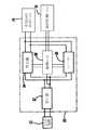
図4が、この実施形態を示している。発電機100は、エンジン(通常は内燃機関である)に接続され、電力を発生する。発電機100は、交流電力を直流に変換する発電機用インバーター102に接続される。発電機用インバーター102と高電圧バッテリー106の両方が、直流バス104に接続される。直流バス104はまた、主インバーター(traction inverter)108にも接続される。通常のHEVにおいて、主インバーター108は、主モーター(traction motor)116に接続される。しかしながら、本発明においては、前述の部品を利用する意図で、主モーター116と主インバーターとの間に接触器110を加えることになる。そして接触器110は、変圧器114に接続されるフィルター112に接続されることになる。それで変圧器114が、外部負荷に接続され得ることになる。 FIG. 4 shows this embodiment. The
この実施形態の動作は、前述のものと同様である。この場合、HEVの一部である主インバーター108が、HPU内に別個のインバーターを加える代りに、利用される。しかしながら、主インバーター108は、HPUと共に動作するための特有の動作ロジックを必要とすることになる。主インバーター108は、高電圧直流電力を交流に(直流300Vを交流300Vへ)変換する。これは、通常、主モーター116を駆動するために、行われる。接触器110は、高電圧交流電力を、主モーター116又は、付加されたHPU構成部品へと、向かわせるスイッチとして機能する。具体的には、HPUの発電機能が選択された場合には、接触器110は、高電圧交流電力をフィルター112へ向かわせ、そこでノイズが除去される。この高電圧交流電力は、それを外部電気機器により利用可能な交流電圧へ変換する変圧器114へ(交流300Vを交流110Vへ)、送られる。 The operation of this embodiment is similar to that described above. In this case, the
[第2実施形態]
第2の代替実施形態において、HPUが同じ結果を生じる様に、別のHEV構成部品が利用される。図5が、第2の代替実施形態を示している。[Second Embodiment]
In a second alternative embodiment, another HEV component is utilized so that the HPU produces the same result. FIG. 5 shows a second alternative embodiment.
発電機130が、発電を補助するために、エンジンに取付けられる。発電機130の出力は、発電機用インバーター132に供給され、そこで、電力が直流へ変換される。発電機のインバーター132及び高電圧バッテリー134は、高電圧直流バス136へと接続される。そして、直流バス136は、DC-DCコンバーター138に接続される。このDC-DCコンバーター138は、高電圧直流電力を低電圧直流電力へ(直流300Vを直流110Vへ)変換する。そして、DC-DCコンバーター138は、直流電力を交流電力へ(直流110Vを交流110Vへ)変えるために、インバーター140に接続される。そして、インバーター140が、信号ノイズを除去するために、フィルター142へ接続される。最終的に、フィルター142は、いかなる外部電気機器にも接続可能である。 A
この第2実施形態において、内燃機関が電力を発生するために発電機130を回すのに用いられるときにのみ、電力は専用のDC-DCコンバーター138及びインバーター140を介して、引き出される。これが、高電圧バッテリーを経由することを、最小限とする。DC-DCコンバーター138及びインバーターは、それらが大きな交流電気負荷を扱うのが可能となる様に、冷却される。 In this second embodiment, power is drawn through the dedicated DC-
この第2実施形態により、このユニットは発電機として動作することも出来る。DC-DCコンバーターの技術は進歩しており、最近は二方向コンバーターが存在する。二方向DC-DCコンバーターが適用され、インバーター140に整流器が加えられるならば、このユニットは、HEVの高電圧バッテリー134を充電するために用いられ得ることになる。具体的には、フィルター142が、外部交流電源に接続されることになる。ここからの交流電力は、整流器を通って進むことになるが、この整流器は、インバーター140が位置する場所に配置されることになり、交流電力を直流電力へ変換する。この整流器は、DC-DCコンバーター138に接続され、低電圧直流電力を高電圧直流電力へ変換する。DC-DCコンバーター138は、高電圧直流バス136に取付けられ、バス136は高電圧バッテリー134に取付けられる。 According to this second embodiment, this unit can also operate as a generator. DC-DC converter technology is advancing, and recently there are two-way converters. If a bi-directional DC-DC converter is applied and a rectifier is added to the
尚、以上の実施形態は、本質的に好ましい例示であって、本発明、その適用物、あるいはその用途の範囲を制限することを意図するものではない。 In addition, the above embodiment is an essentially preferable illustration, Comprising: It does not intend restrict | limiting the range of this invention, its application thing, or its use.
以上説明したように、本発明は、車両バッテリー用の汎用畜電器として機能すると共に、電動工具の様な外部電気機器を作動させるための発電機として機能する、ハイブリッド電気自動車用のホーム・パワー・ユニットについて有用である。 As described above, the present invention functions as a general-purpose livestock battery for a vehicle battery, and functions as a generator for operating an external electric device such as a power tool. Useful for units.
50, 80 ホーム・パワー・ユニット装置
82, 114 変圧器
84 整流手段
86 インバーター手段
88 制御ユニット50, 80 Home power unit equipment
82, 114 transformers
84 Rectifying means
86 Inverter means
88 Control unit
Claims (10)
Translated fromJapanese電圧を変換する変圧器、
直流を交流へ変換するインバーター手段、
交流を直流に変換する整流手段、
制御ユニット、
上記ハイブリッド電気自動車及び外部電気負荷又は外部電源への接続手段、及び
充電機能と発電機能との間で動作を変更するための切替手段を有し、
上記発電機能においては、少なくとも、駆動系に接続された発電機から上記外部電気負荷へ電力を直接供給する装置。A home power unit device that functions as a battery charger or generator in a hybrid electric vehicle,
Transformer to convert voltage,
Inverter means for converting direct current to alternating current,
Rectifying means for converting alternating current to direct current,
Controller unit,
A means for connecting to the hybrid electric vehicle and an external electric load or an external power source, and a switching means for changing the operation between the charging function and the power generation function;
In the power generation function, at least a device that directly supplies power to the external electric load from a generator connected to a drive system.
上記接触器は、上記インバーター手段からの交流電力を上記変圧器及び上記モータの何れかに切り替えて伝送する、請求項2の装置。The switching means further includes a contactor to which the inverter means, the motor of the hybrid electric vehicle, and the transformer are connected,
The apparatus according to claim 2, wherein the contactor switches AC power from the inverter means to either the transformer or the motor for transmission.
Applications Claiming Priority (1)
| Application Number | Priority Date | Filing Date | Title |
|---|---|---|---|
| US09/659,018US6724100B1 (en) | 2000-09-08 | 2000-09-08 | HEV charger/generator unit |
Related Parent Applications (1)
| Application Number | Title | Priority Date | Filing Date |
|---|---|---|---|
| JP2001272266ADivisionJP2002165306A (en) | 2000-09-08 | 2001-09-07 | Charger, and generator unit for hybrid electric vehicle |
Publications (1)
| Publication Number | Publication Date |
|---|---|
| JP2010241427Atrue JP2010241427A (en) | 2010-10-28 |
Family
ID=24643701
Family Applications (2)
| Application Number | Title | Priority Date | Filing Date |
|---|---|---|---|
| JP2001272266APendingJP2002165306A (en) | 2000-09-08 | 2001-09-07 | Charger, and generator unit for hybrid electric vehicle |
| JP2010115555APendingJP2010241427A (en) | 2000-09-08 | 2010-05-19 | Charger/generator unit for hybrid electric vehicle |
Family Applications Before (1)
| Application Number | Title | Priority Date | Filing Date |
|---|---|---|---|
| JP2001272266APendingJP2002165306A (en) | 2000-09-08 | 2001-09-07 | Charger, and generator unit for hybrid electric vehicle |
Country Status (5)
| Country | Link |
|---|---|
| US (1) | US6724100B1 (en) |
| EP (1) | EP1201485B1 (en) |
| JP (2) | JP2002165306A (en) |
| CA (1) | CA2350177A1 (en) |
| DE (1) | DE60110520T2 (en) |
Cited By (6)
| Publication number | Priority date | Publication date | Assignee | Title |
|---|---|---|---|---|
| JP2013198293A (en)* | 2012-03-19 | 2013-09-30 | Honda Motor Co Ltd | Power supply system |
| JP2013207860A (en)* | 2012-03-27 | 2013-10-07 | Mitsubishi Motors Corp | Vehicle with power supply device |
| US8768533B2 (en)* | 2010-04-09 | 2014-07-01 | Toyota Jidosha Kabushiki Kaisha | Vehicle, communication system, and communication device |
| US8772961B2 (en) | 2010-04-09 | 2014-07-08 | Toyota Jidosha Kabushiki Kaisha | Communication device, communication system, and vehicle |
| CN113511060A (en)* | 2020-03-25 | 2021-10-19 | Ip传输控股公司 | Vehicle propulsion system |
| JP7561016B2 (en) | 2020-12-01 | 2024-10-03 | 株式会社Subaru | Vehicle control device |
Families Citing this family (78)
| Publication number | Priority date | Publication date | Assignee | Title |
|---|---|---|---|---|
| US6892840B2 (en)* | 1999-05-05 | 2005-05-17 | Daniel J. Meaney, Jr. | Hybrid electric vehicle having alternate power sources |
| JP3852321B2 (en)* | 2001-10-22 | 2006-11-29 | トヨタ自動車株式会社 | HV drive structure and method with cranking support torque increasing means |
| US7174978B2 (en)* | 2002-03-29 | 2007-02-13 | Aisin Aw Co., Ltd. | Hybrid drive unit, and front-engine/rear-drive type automobile having the hybrid drive unit mounted thereon |
| DE10224808A1 (en)* | 2002-06-05 | 2003-12-18 | Aloys Wobben | Process and device for transporting electrical energy has multi element electricity store on a vehicle and transmits the electricity by discharging the store |
| JP2004187329A (en)* | 2002-10-11 | 2004-07-02 | Yamaha Motor Co Ltd | Electrically driven vehicle |
| FR2847523B1 (en)* | 2002-11-27 | 2005-09-02 | Peugeot Citroen Automobiles Sa | HYBRID TRACTION VEHICLE HAVING A DEVICE FOR CONTROLLING THE CHARGE OF THE BATTERY |
| US7268454B2 (en)* | 2003-01-17 | 2007-09-11 | Magnetic Torque International, Ltd. | Power generating systems |
| US7233088B2 (en)* | 2003-01-17 | 2007-06-19 | Magnetic Torque International, Ltd. | Torque converter and system using the same |
| US7353084B2 (en)* | 2003-02-27 | 2008-04-01 | Acutra, Inc. | Generator controller |
| JP4438417B2 (en)* | 2004-01-13 | 2010-03-24 | トヨタ自動車株式会社 | AC voltage generator and power output device |
| US7057376B2 (en)* | 2004-01-14 | 2006-06-06 | Vanner, Inc. | Power management system for vehicles |
| US7002317B2 (en)* | 2004-02-18 | 2006-02-21 | Honeywell International Inc. | Matched reactance machine power-generation system |
| KR20040030751A (en)* | 2004-02-24 | 2004-04-09 | 주식회사 강진 콘 베어 | Generator for vehicles |
| JP2005299417A (en)* | 2004-04-07 | 2005-10-27 | Toyota Motor Corp | Exhaust heat generator and automobile equipped with the same |
| EP1782527B1 (en)* | 2004-08-26 | 2009-09-30 | ABB Schweiz AG | Device for feeding auxiliary operating devices for a fuel electric vehicle |
| JP2006112879A (en) | 2004-10-14 | 2006-04-27 | Yamaha Motor Co Ltd | Relative position detector and saddle ride type vehicle |
| JP4401926B2 (en) | 2004-10-14 | 2010-01-20 | ヤマハ発動機株式会社 | Relative position detection control device and saddle riding type vehicle |
| JP4245546B2 (en) | 2004-11-04 | 2009-03-25 | トヨタ自動車株式会社 | Power output apparatus and vehicle equipped with the same |
| JP2006158123A (en)* | 2004-11-30 | 2006-06-15 | Toyota Motor Corp | AC voltage output device and vehicle equipped with the same |
| EP1847166A3 (en)* | 2006-04-20 | 2008-11-12 | Antonio Romano Moszoro | Electric installation applied to an agricultural tractor to be used in coupled tools |
| JP4812529B2 (en)* | 2006-06-14 | 2011-11-09 | トヨタ自動車株式会社 | Power supply device and vehicle |
| US8556009B2 (en)* | 2006-12-19 | 2013-10-15 | Bradley Wayne Bartilson | Safe, super-efficient, four-wheeled vehicle employing large diameter wheels with continuous-radius tires, with leaning option |
| US7642755B2 (en)* | 2006-12-19 | 2010-01-05 | Bradley Wayne Bartilson | Method and apparatus to maximize stored energy in UltraCapacitor Systems |
| US8100216B2 (en)* | 2006-12-19 | 2012-01-24 | Bradley Wayne Bartilson | Hybrid drivetrain with waste heat energy conversion into electricity |
| US7808214B2 (en)* | 2006-12-19 | 2010-10-05 | Bradley Wayne Bartilson | Short-cycling serial hybrid drivetrain with high power density storage |
| DE102007004172A1 (en) | 2007-01-27 | 2008-07-31 | Volkswagen Ag | Motor vehicle e.g. zero emission vehicle, has generator activated and/or deactivated in parking condition of vehicle and started after activation of drive, where disconnection of drive of generator is carried out after deactivation |
| US20080180058A1 (en)* | 2007-01-30 | 2008-07-31 | Bijal Patel | Plug-in battery charging booster for electric vehicle |
| US7989980B2 (en)* | 2007-03-02 | 2011-08-02 | Blackman Tracy D | Portable self regenerating power system |
| NL1033557C2 (en)* | 2007-03-19 | 2008-09-22 | Fokko Rekker | Vehicle, alternator for use herein, and method for driving an external load. |
| US7812555B2 (en)* | 2007-04-30 | 2010-10-12 | Caterpillar Inc | Electric powertrain system having bidirectional DC generator |
| US8004267B2 (en)* | 2007-08-21 | 2011-08-23 | Ford Global Technologies, Llc | Power converter system for an automotive vehicle and method for configuring same |
| JP4305553B2 (en)* | 2007-10-23 | 2009-07-29 | トヨタ自動車株式会社 | Electric vehicle |
| US20110169273A1 (en)* | 2008-09-26 | 2011-07-14 | Arb Greenpower, Llc | Hybrid energy conversion system |
| US8080973B2 (en) | 2008-10-22 | 2011-12-20 | General Electric Company | Apparatus for energy transfer using converter and method of manufacturing same |
| US7932633B2 (en) | 2008-10-22 | 2011-04-26 | General Electric Company | Apparatus for transferring energy using power electronics and machine inductance and method of manufacturing same |
| US8324859B2 (en) | 2008-12-15 | 2012-12-04 | Comverge, Inc. | Method and system for co-operative charging of electric vehicles |
| US8106627B1 (en) | 2008-12-15 | 2012-01-31 | Comverge, Inc. | Method and system for co-operative charging of electric vehicles |
| DE102009000051A1 (en)* | 2009-01-07 | 2010-07-08 | Robert Bosch Gmbh | Method for operating a vehicle electrical system with at least two subnetworks |
| US9511659B2 (en)* | 2009-01-28 | 2016-12-06 | Steven Young | Method and apparatus for lawn care |
| US20100240491A1 (en)* | 2009-03-17 | 2010-09-23 | Parag Vyas | System for vehicle propulsion having and method of making same |
| US8535200B2 (en)* | 2009-03-17 | 2013-09-17 | General Electric Company | Vehicle propulsion system having a continuously variable transmission and method of making same |
| DE102009001705A1 (en)* | 2009-03-20 | 2010-09-23 | Robert Bosch Gmbh | Electric vehicle with a battery charger |
| FR2945899B1 (en)* | 2009-05-25 | 2014-04-11 | Peugeot Citroen Automobiles Sa | SYSTEM FOR RECHARGING A POWER SUPPLY BATTERY OF AN ELECTRIC MOTOR AND VEHICLE EQUIPPED WITH SUCH A SYSTEM. |
| US20100320964A1 (en)* | 2009-06-18 | 2010-12-23 | Ford Global Technologies, Llc | Method And System To Charge Batteries Only While Vehicle Is Parked |
| US8393423B2 (en)* | 2009-06-18 | 2013-03-12 | Ford Global Technologies, Llc | Method and system to prevent vehicle driveaway during battery charging |
| US8239068B1 (en) | 2009-06-26 | 2012-08-07 | Comverge, Inc. | Method and system for cooperative powering of unitary air conditioners |
| DE102009045639A1 (en)* | 2009-10-13 | 2011-04-14 | Robert Bosch Gmbh | Electrical connection device for hybrid and electric vehicles and associated method for charging |
| CN102092301B (en)* | 2009-12-09 | 2012-10-10 | 财团法人工业技术研究院 | Charging/starting systems and applications for electric vehicles |
| US8698451B2 (en) | 2009-12-18 | 2014-04-15 | General Electric Company | Apparatus and method for rapid charging using shared power electronics |
| WO2011103283A1 (en)* | 2010-02-17 | 2011-08-25 | Lg Electronics Inc. | A movable component for a network system |
| US8798834B2 (en)* | 2010-02-17 | 2014-08-05 | Lg Electronics Inc. | Movable component for a network system |
| TWI408878B (en)* | 2010-07-14 | 2013-09-11 | Kwang Yang Motor Co | Vehicle power generation device |
| US8378623B2 (en) | 2010-11-05 | 2013-02-19 | General Electric Company | Apparatus and method for charging an electric vehicle |
| US9290097B2 (en) | 2010-11-05 | 2016-03-22 | Robert Louis Steigerwald | Apparatus for transferring energy using onboard power electronics with high-frequency transformer isolation and method of manufacturing same |
| WO2012066438A2 (en)* | 2010-11-17 | 2012-05-24 | Brusa Elektronik Ag | Energy supply unit for an electric motor vehicle as well as electric motor vehicle |
| DE102011004355A1 (en)* | 2011-02-18 | 2012-08-23 | Continental Automotive Gmbh | Module for power distribution in an electrically powered vehicle |
| CN102214947A (en)* | 2011-05-31 | 2011-10-12 | 贵州詹阳动力重工有限公司 | Battery charging system of hybrid electric tractor |
| US8994327B2 (en) | 2011-08-24 | 2015-03-31 | General Electric Company | Apparatus and method for charging an electric vehicle |
| US9013062B2 (en)* | 2011-11-24 | 2015-04-21 | Toyota Jidosha Kabushiki Kaisha | Vehicle, control method for vehicle, and power reception facilities |
| US9520741B2 (en) | 2011-11-28 | 2016-12-13 | General Electric Company | System for charging electrical storage device and method of making same |
| JP5872298B2 (en)* | 2012-01-13 | 2016-03-01 | 株式会社日立製作所 | Power supply system and automobile control device capable of supplying power to outside |
| US9340114B2 (en) | 2012-01-23 | 2016-05-17 | Ford Global Technologies, Llc | Electric vehicle with transient current management for DC-DC converter |
| JP5716694B2 (en)* | 2012-03-01 | 2015-05-13 | トヨタ自動車株式会社 | Electric vehicle |
| DE102013008420A1 (en)* | 2013-05-17 | 2014-11-20 | Abb Technology Ag | Drive unit for controlling a motor |
| CN104249630B (en)* | 2013-06-28 | 2017-08-04 | 比亚迪股份有限公司 | Electric vehicles and systems for external power supply of electric vehicles |
| JP6241145B2 (en)* | 2013-08-30 | 2017-12-06 | 株式会社オートネットワーク技術研究所 | Control system |
| US10259443B2 (en) | 2013-10-18 | 2019-04-16 | Ford Global Technologies, Llc | Hybrid-electric vehicle plug-out mode energy management |
| US9272628B2 (en)* | 2013-12-09 | 2016-03-01 | Textron Inc. | Using AC induction motor as a generator in a utility vehicle |
| US9719477B2 (en) | 2013-12-09 | 2017-08-01 | Textron Inc. | Using a DC or AC generator as a starter with fault detection |
| KR101745099B1 (en) | 2015-06-15 | 2017-06-20 | 현대자동차주식회사 | Safety apparatus for portable power generation of fuel cell vehicle and operation method thereof |
| US11479139B2 (en) | 2015-09-11 | 2022-10-25 | Invertedpower Pty Ltd | Methods and systems for an integrated charging system for an electric vehicle |
| CA2997565A1 (en) | 2015-09-11 | 2017-03-16 | Invertedpower Pty Ltd | A controller for an inductive load having one or more inductive windings |
| US10507716B2 (en) | 2016-04-25 | 2019-12-17 | General Electric Company | Integrated charger for vehicles and method of making same |
| US10710461B2 (en) | 2016-11-11 | 2020-07-14 | Ford Global Technologies, Llc | Absorbing power down energy of an external motor device in a power generation vehicle |
| US11267358B2 (en) | 2017-05-08 | 2022-03-08 | Invertedpower Pty Ltd | Vehicle charging station |
| US11642965B2 (en) | 2018-10-11 | 2023-05-09 | Keith Johnson | System and method of powering an external device with a vehicular battery system |
| CN112428877A (en)* | 2019-08-26 | 2021-03-02 | 上海西门子医疗器械有限公司 | Power supply system, electric motor coach and vehicle-mounted medical imaging equipment |
| WO2024191880A1 (en)* | 2023-03-10 | 2024-09-19 | Liquidpiston, Inc. | Mobile engine-generator vehicle |
Citations (5)
| Publication number | Priority date | Publication date | Assignee | Title |
|---|---|---|---|---|
| JPH0368577U (en)* | 1989-11-10 | 1991-07-05 | ||
| JPH07255105A (en)* | 1994-03-11 | 1995-10-03 | Suzuki Motor Corp | Electric vehicle |
| JPH0956007A (en)* | 1995-08-10 | 1997-02-25 | Aqueous Res:Kk | Hybrid vehicle |
| JPH11178234A (en)* | 1997-12-10 | 1999-07-02 | Nissan Motor Co Ltd | Home power supply system using electric vehicles |
| JP2000234539A (en)* | 1998-12-15 | 2000-08-29 | Toyota Motor Corp | Control device for hybrid vehicle |
Family Cites Families (22)
| Publication number | Priority date | Publication date | Assignee | Title |
|---|---|---|---|---|
| US3655991A (en)* | 1971-02-08 | 1972-04-11 | Modern Ind Inc | Power output unit and method for delivering constant frequency, constant voltage ac power |
| US3953740A (en) | 1971-09-30 | 1976-04-27 | Cliff Granberry Corporation | Remote power supply units for vehicles |
| US3824404A (en) | 1973-04-03 | 1974-07-16 | L Ghere | Vehicle power output means |
| US3790808A (en) | 1973-05-02 | 1974-02-05 | Bel Tronics Ltd | Power take-off switch |
| US4074145A (en) | 1977-04-18 | 1978-02-14 | Laffoon Perry D | Electric power generating apparatus |
| US4159515A (en) | 1978-03-17 | 1979-06-26 | Walkowiak Paul S | Inverter control system |
| US4182960A (en)* | 1978-05-30 | 1980-01-08 | Reuyl John S | Integrated residential and automotive energy system |
| US5066866A (en) | 1989-12-26 | 1991-11-19 | Hallidy William M | Power converter system |
| AU669853B2 (en)* | 1991-08-01 | 1996-06-27 | Ea Technology Limited | Battery powered electric vehicle and electrical supply system |
| DE4205331C2 (en)* | 1992-02-21 | 1997-02-06 | Audi Ag | Use of a device integrated in a vehicle for utilizing solar energy |
| US5343970A (en) | 1992-09-21 | 1994-09-06 | Severinsky Alex J | Hybrid electric vehicle |
| JP3178146B2 (en)* | 1992-12-25 | 2001-06-18 | 富士電機株式会社 | Electric vehicle electric system |
| US5861800A (en)* | 1996-06-12 | 1999-01-19 | Chrysler Corporation | Ignition interlock and PRNDL indicator powering switch |
| US5952812A (en)* | 1996-11-26 | 1999-09-14 | Nippon Soken, Inc. | AC-DC power converting device |
| US5865258A (en)* | 1997-01-13 | 1999-02-02 | Mcgrew, Ii; Jeff | Golf course maintenance machine |
| DE19722644C1 (en)* | 1997-05-30 | 1998-09-17 | Aeg Anglo Batteries Germany Gm | Additional AC network for electric vehicle with high power battery |
| JP3382506B2 (en)* | 1997-06-26 | 2003-03-04 | 株式会社東海理化電機製作所 | Display device |
| US6275231B1 (en)* | 1997-08-01 | 2001-08-14 | American Calcar Inc. | Centralized control and management system for automobiles |
| JPH11178241A (en)* | 1997-12-15 | 1999-07-02 | Mitsubishi Electric Corp | Power supply during power outage |
| US6281600B1 (en)* | 1999-07-01 | 2001-08-28 | Deere & Company | Jump start system for vehicles having different operating voltages |
| DE19935873A1 (en)* | 1999-07-30 | 2001-03-01 | Zahnradfabrik Friedrichshafen | Electrical circuit for hybrid vehicle has intermediate circuit stage coupling traction battery to electric motor and to battery charging generator driven by i.c. engine |
| ES2279746T5 (en)* | 1999-12-21 | 2019-10-22 | Siemens Mobility GmbH | Drive unit |
- 2000
- 2000-09-08USUS09/659,018patent/US6724100B1/ennot_activeExpired - Lifetime
- 2001
- 2001-06-12CACA002350177Apatent/CA2350177A1/ennot_activeAbandoned
- 2001-08-21DEDE60110520Tpatent/DE60110520T2/ennot_activeExpired - Lifetime
- 2001-08-21EPEP01000394Apatent/EP1201485B1/ennot_activeExpired - Lifetime
- 2001-09-07JPJP2001272266Apatent/JP2002165306A/enactivePending
- 2010
- 2010-05-19JPJP2010115555Apatent/JP2010241427A/enactivePending
Patent Citations (5)
| Publication number | Priority date | Publication date | Assignee | Title |
|---|---|---|---|---|
| JPH0368577U (en)* | 1989-11-10 | 1991-07-05 | ||
| JPH07255105A (en)* | 1994-03-11 | 1995-10-03 | Suzuki Motor Corp | Electric vehicle |
| JPH0956007A (en)* | 1995-08-10 | 1997-02-25 | Aqueous Res:Kk | Hybrid vehicle |
| JPH11178234A (en)* | 1997-12-10 | 1999-07-02 | Nissan Motor Co Ltd | Home power supply system using electric vehicles |
| JP2000234539A (en)* | 1998-12-15 | 2000-08-29 | Toyota Motor Corp | Control device for hybrid vehicle |
Cited By (6)
| Publication number | Priority date | Publication date | Assignee | Title |
|---|---|---|---|---|
| US8768533B2 (en)* | 2010-04-09 | 2014-07-01 | Toyota Jidosha Kabushiki Kaisha | Vehicle, communication system, and communication device |
| US8772961B2 (en) | 2010-04-09 | 2014-07-08 | Toyota Jidosha Kabushiki Kaisha | Communication device, communication system, and vehicle |
| JP2013198293A (en)* | 2012-03-19 | 2013-09-30 | Honda Motor Co Ltd | Power supply system |
| JP2013207860A (en)* | 2012-03-27 | 2013-10-07 | Mitsubishi Motors Corp | Vehicle with power supply device |
| CN113511060A (en)* | 2020-03-25 | 2021-10-19 | Ip传输控股公司 | Vehicle propulsion system |
| JP7561016B2 (en) | 2020-12-01 | 2024-10-03 | 株式会社Subaru | Vehicle control device |
Also Published As
| Publication number | Publication date |
|---|---|
| JP2002165306A (en) | 2002-06-07 |
| US6724100B1 (en) | 2004-04-20 |
| EP1201485B1 (en) | 2005-05-04 |
| DE60110520T2 (en) | 2005-10-13 |
| CA2350177A1 (en) | 2002-03-08 |
| EP1201485A1 (en) | 2002-05-02 |
| DE60110520D1 (en) | 2005-06-09 |
Similar Documents
| Publication | Publication Date | Title |
|---|---|---|
| JP2010241427A (en) | Charger/generator unit for hybrid electric vehicle | |
| US8924057B2 (en) | Method for starting a hybrid vehicle | |
| US7733039B2 (en) | Electric vehicle system for charging and supplying electrical power | |
| EP1976721B1 (en) | Vehicle propulsion system | |
| US6930460B2 (en) | Load driver with power storage unit | |
| US7764044B2 (en) | Motor driving apparatus capable of driving motor with reliability | |
| EP1889349B1 (en) | Vehicular power supply system and vehicle | |
| JP4305553B2 (en) | Electric vehicle | |
| CN101729020B (en) | Apparatus for energy transfer using a converter and method of manufacturing the same | |
| CA2545552C (en) | Method and apparatus for producing tractive effort | |
| CN101460333B (en) | Vehicle drive system and vehicle equipped with it | |
| US7649335B2 (en) | Vehicular power supply system and vehicle | |
| US9340114B2 (en) | Electric vehicle with transient current management for DC-DC converter | |
| JP5825423B2 (en) | Electric vehicle and control method thereof | |
| KR20080003905A (en) | Plug-in hybrid vehicles with fast energy storage | |
| JP2009508763A (en) | Plug-in hybrid propulsion power electronics equipment with high-speed energy storage device and control method and apparatus | |
| KR20160050953A (en) | Apparatus for converting power of electric vehicle | |
| JP2006254565A (en) | Power supply device and motor drive device including the same | |
| CN114475282B (en) | A power system of an extended-range electric vehicle | |
| JP4329454B2 (en) | Electric vehicle system | |
| Al-Adsani et al. | An ICE/HPM generator range extender in a series hybrid electric vehicle | |
| KR102138343B1 (en) | Multifunctional and highly integrated power converter component | |
| JP2007089320A (en) | Electrical system | |
| Maggetto et al. | Electric vehicles, hybrid electric vehicles and fuel cell electric vehicles: What in the future |
Legal Events
| Date | Code | Title | Description |
|---|---|---|---|
| A131 | Notification of reasons for refusal | Free format text:JAPANESE INTERMEDIATE CODE: A131 Effective date:20120124 | |
| A02 | Decision of refusal | Free format text:JAPANESE INTERMEDIATE CODE: A02 Effective date:20120626 |