JP2010238094A - Operation input device, operation input method and program - Google Patents
Operation input device, operation input method and programDownload PDFInfo
- Publication number
- JP2010238094A JP2010238094AJP2009087096AJP2009087096AJP2010238094AJP 2010238094 AJP2010238094 AJP 2010238094AJP 2009087096 AJP2009087096 AJP 2009087096AJP 2009087096 AJP2009087096 AJP 2009087096AJP 2010238094 AJP2010238094 AJP 2010238094A
- Authority
- JP
- Japan
- Prior art keywords
- target
- unit
- unstable
- data
- input
- Prior art date
- Legal status (The legal status is an assumption and is not a legal conclusion. Google has not performed a legal analysis and makes no representation as to the accuracy of the status listed.)
- Pending
Links
Images


Classifications
- G—PHYSICS
- G06—COMPUTING OR CALCULATING; COUNTING
- G06F—ELECTRIC DIGITAL DATA PROCESSING
- G06F3/00—Input arrangements for transferring data to be processed into a form capable of being handled by the computer; Output arrangements for transferring data from processing unit to output unit, e.g. interface arrangements
- G06F3/01—Input arrangements or combined input and output arrangements for interaction between user and computer
- G06F3/03—Arrangements for converting the position or the displacement of a member into a coded form
- G06F3/041—Digitisers, e.g. for touch screens or touch pads, characterised by the transducing means
- G06F3/0416—Control or interface arrangements specially adapted for digitisers
- G06F3/0418—Control or interface arrangements specially adapted for digitisers for error correction or compensation, e.g. based on parallax, calibration or alignment
- G—PHYSICS
- G06—COMPUTING OR CALCULATING; COUNTING
- G06F—ELECTRIC DIGITAL DATA PROCESSING
- G06F3/00—Input arrangements for transferring data to be processed into a form capable of being handled by the computer; Output arrangements for transferring data from processing unit to output unit, e.g. interface arrangements
- G06F3/01—Input arrangements or combined input and output arrangements for interaction between user and computer
- G06F3/03—Arrangements for converting the position or the displacement of a member into a coded form
- G06F3/041—Digitisers, e.g. for touch screens or touch pads, characterised by the transducing means
- G06F3/042—Digitisers, e.g. for touch screens or touch pads, characterised by the transducing means by opto-electronic means
Landscapes
- Engineering & Computer Science (AREA)
- General Engineering & Computer Science (AREA)
- Theoretical Computer Science (AREA)
- Human Computer Interaction (AREA)
- Physics & Mathematics (AREA)
- General Physics & Mathematics (AREA)
- Position Input By Displaying (AREA)
- Control Of Indicators Other Than Cathode Ray Tubes (AREA)
Abstract
Description
Translated fromJapanese本発明は、操作入力装置および操作入力方法、並びにプログラムに関し、特に、操作入力に対して正確な動作をすることができるようにした操作入力装置および操作入力方法、並びにプログラムに関する。 The present invention relates to an operation input device, an operation input method, and a program, and more particularly to an operation input device, an operation input method, and a program that can perform an accurate operation with respect to the operation input.
従来、パネル上の点に関する情報を、複数の点について出力可能なパネルとして、例えば、液晶表示装置に光センサを内蔵させ、外部からの光の入力を光センサで検出することにより、光による入力が可能な表示パネル(以下、入出力パネルともいう)が提案されている(例えば、特許文献1参照)。 Conventionally, as a panel that can output information on points on a panel for a plurality of points, for example, a liquid crystal display device has a built-in optical sensor, and light input from the outside is detected by the optical sensor. There has been proposed a display panel (hereinafter also referred to as an input / output panel) (see, for example, Patent Document 1).
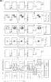
図1を参照して、従来の入出力パネルについて説明する。 A conventional input / output panel will be described with reference to FIG.
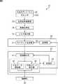
図1の入出力パネル11は、入出力ディスプレイ12、受光信号処理部13、画像処理部14、生成部15、および制御部16を備えて構成される。 The input /
入出力ディスプレイ12は、画像の表示と、外部からの入力に対応する光の検出とを行う。例えば、入出力ディスプレイ12は、表示画面全体に分布するように配置された複数の光センサ12Aを内蔵しており、光センサ12Aが、外部から入射する光を受光し、その光の受光量に対応する受光信号を生成して、受光信号処理部13に供給する。 The input / output display 12 displays an image and detects light corresponding to an input from the outside. For example, the input / output display 12 includes a plurality of photosensors 12A arranged so as to be distributed over the entire display screen. The photosensor 12A receives light incident from the outside and determines the amount of received light. A corresponding received light signal is generated and supplied to the received light signal processing unit 13.
受光信号処理部13は、入出力ディスプレイ12から供給される受光信号に対して、所定の処理を施すことにより、受光信号の輝度に応じた画像を生成し、画像処理部14に供給する。 The light reception signal processing unit 13 performs predetermined processing on the light reception signal supplied from the input / output display 12 to generate an image corresponding to the luminance of the light reception signal and supplies the image to the
画像処理部14は、受光信号処理部13から供給される画像に対して、所定の画像処理を施すことにより、入出力ディスプレイ12の表示画面に、ユーザの指などの物体が接触している部分を、外部からの入力があった入力部分として検出する。そして、画像処理部14は、その入力部分の点情報として、入力位置の座標、入力部分の接触面積、入力部分の形状(接触領域)を生成し、生成部15に供給する。 The
生成部15は、ターゲット生成部17および記憶部18を有しており、記憶部18には、ターゲット生成部17から1フレームごとに出力されるターゲット情報が記憶される。ターゲット生成部17は、画像処理部14から供給される入力部分の点情報に対し、フレームごとに、記憶部18に記憶されている全フレームでのターゲット情報との統合処理を施すことにより、ターゲット情報を生成する。ターゲット情報は、入力部分の時間的または空間的な位置関係に基づいて、一連の入力を表す識別用のIDが割り振られた情報である。 The
制御部16は、生成部15により生成されたターゲット情報に基づいて、必要に応じて、入出力ディスプレイ12に供給される画像データを制御することにより、入出力ディスプレイ12の表示状態を変化させる。 The
ところで、従来の入出力ディスプレイ12では、周囲環境光の照度変化や、フラッシュなどの発光装置による一時的な高輝度の照射などにより、入出力ディスプレイ12の表面への照射光の時間的または空間的な変化に起因して、入出力ディスプレイ12上の物体の非接触部分にも点情報が生成されることがある。例えば、入出力ディスプレイ12から離れたところで指が動いているときに照度変化があると、その指の影の端部が点情報として生成される。このような非接触部分に発生した点情報に対して、上位のアプリケーションが接触部分と同様の反応をすることで誤動作が発生する。 By the way, in the conventional input / output display 12, the temporal or spatial of the irradiation light to the surface of the input / output display 12 by the illuminance change of ambient environmental light, temporary high-intensity irradiation by light emitting devices, such as a flash, etc. Due to such a change, point information may be generated also in a non-contact portion of an object on the input / output display 12. For example, if there is a change in illuminance when the finger is moving away from the input / output display 12, the edge of the finger's shadow is generated as point information. A malfunction occurs when the host application reacts to the point information generated in such a non-contact portion in the same manner as the contact portion.
また、例えば、指などの非完全反射物(光を完全に遮蔽することなく、光を若干透過させる物体)が接触している場合、入出力ディスプレイ12の表面への照射光の時間的または空間的な変化が発生したとき、接触部分の点情報が一時的に消滅することがある。そのような点情報を受け取った生成部15は、点情報が消滅した前後のフレームで、異なるIDが割り振られたターゲット情報を生成することになる。このため、例えば、一連の指の接触中に急峻な外光変化が発生すると、その急峻な外光変化により点情報が消滅し、その後のターゲット処理において、指の接触が2回あったと認識されて、上位のアプリケーションにおいて誤作動が発生することがある。 In addition, for example, when a non-completely reflecting object such as a finger (an object that transmits light slightly without blocking light completely) is in contact, the time or space of the irradiation light to the surface of the input / output display 12 When a general change occurs, the point information of the contact portion may disappear temporarily. The
上述したように、従来の入出力パネルでは、照射光の変化によって、非接触部分に点情報が発生したり、一時的に点情報が消滅したりすることがある。そのような点情報に基づいて生成されたターゲット情報に基づいて上位のアプリケーションが処理を行うと、誤動作が発生することになる。即ち、操作入力に対して正確な動作が行われないことがあった。 As described above, in the conventional input / output panel, point information may be generated in a non-contact portion or the point information may disappear temporarily due to a change in irradiation light. If a higher-level application performs processing based on target information generated based on such point information, a malfunction occurs. That is, an accurate operation may not be performed in response to an operation input.
本発明は、このような状況に鑑みてなされたものであり、操作入力に対して正確な動作をすることができるようにするものである。 The present invention has been made in view of such a situation, and makes it possible to perform an accurate operation in response to an operation input.
本発明の一側面の操作入力装置は、画像を表示する表示画面に対して、外部からの前記表示画面に対する複数の操作入力に対応する光の検出を行う入出力手段と、外部から入力があった入力部分の時間的若しくは空間的な位置関係に基づいて、一連の入力を表すターゲットの情報を生成するターゲット生成手段と、前記ターゲット生成手段により生成されたターゲットが一時的に消失したときに、消失した前記ターゲットを補完する消失データ補完手段と、前記ターゲット生成手段により不安定なターゲットが生成されたときに、不安定な前記ターゲットを除去する不安定データ除去手段と、前記消失データ補完手段による処理と、前記不安定データ除去手段による処理とのいずれかを選択する処理選択手段を備える。 An operation input device according to one aspect of the present invention has an input / output unit that detects light corresponding to a plurality of operation inputs to the display screen from the outside, and an input from the outside, on a display screen that displays an image. Based on the temporal or spatial positional relationship of the input part, target generation means for generating target information representing a series of inputs, and when the target generated by the target generation means temporarily disappears, By lost data complementing means for complementing the lost target, unstable data removing means for removing the unstable target when the target generating means generates an unstable target, and the lost data complementing means Processing selection means for selecting either processing or processing by the unstable data removing means is provided.
本発明の一側面の操作入力方法またはプログラムは、画像を表示する表示画面に対して、外部からの前記表示画面に対する複数の操作入力に対応する光の検出を行い、外部から入力があった入力部分の時間的若しくは空間的な位置関係に基づいて、一連の入力を表すターゲットの情報を生成し、生成されたターゲットが一時的に消失したときに、消失した前記ターゲットを補完し、不安定なターゲットが生成されたときに、不安定な前記ターゲットを除去し、前記ターゲットを補完する処理と、不安定な前記ターゲットを除去する処理とのいずれかを選択するステップを含む。 An operation input method or program according to one aspect of the present invention detects light corresponding to a plurality of operation inputs to the display screen from the outside on a display screen displaying an image, and inputs from the outside Generates target information that represents a series of inputs based on the temporal or spatial positional relationship of the parts, and when the generated target temporarily disappears, the lost target is complemented and unstable. When a target is generated, the method includes a step of removing the unstable target and selecting one of a process of complementing the target and a process of removing the unstable target.
本発明の一側面においては、画像を表示する表示画面に対して、外部からの表示画面に対する複数の操作入力に対応する光の検出が行われ、外部から入力があった入力部分の時間的若しくは空間的な位置関係に基づいて、一連の入力を表すターゲットの情報が生成される。また、生成されたターゲットが一時的に消失したときに、消失したターゲットが補完され、不安定なターゲットが生成されたときに、不安定なターゲットが除去される。そして、ターゲットを補完する処理と、不安定なターゲットを除去する処理とのいずれかが選択される。 In one aspect of the present invention, light corresponding to a plurality of operation inputs to an external display screen is detected for a display screen that displays an image, and an input portion that is input from the outside is detected temporally or Based on the spatial positional relationship, target information representing a series of inputs is generated. In addition, when the generated target is temporarily lost, the lost target is complemented, and when the unstable target is generated, the unstable target is removed. Then, either a process for complementing the target or a process for removing the unstable target is selected.
本発明の一側面によれば、操作入力に対して正確な動作をすることができる。 According to one aspect of the present invention, an accurate operation can be performed in response to an operation input.
以下、本発明を適用した具体的な実施の形態について、図面を参照しながら詳細に説明する。 Hereinafter, specific embodiments to which the present invention is applied will be described in detail with reference to the drawings.
図2は、本発明を適用した操作入力装置の第1の実施の形態の構成例を示すブロック図である。 FIG. 2 is a block diagram showing a configuration example of the first embodiment of the operation input device to which the present invention is applied.
図2において、操作入力装置21は、入出力ディスプレイ22、受光信号処理部23、画像処理部24、ノイズ除去部25、生成部26、修正部27、および制御部28を備えて構成される。 In FIG. 2, the
入出力ディスプレイ22は、画像の表示と、外部からの入力に対応する光の検出とを行う。即ち、入出力ディスプレイ22は、図示しない表示信号処理部から供給される画像データに対応する画像を、その表示画面に表示する。また、入出力ディスプレイ22は、例えば、表示画面全体に分布するように配置された複数の光センサ22Aを内蔵し、外部から入射する光を受光し、その光の受光量に対応する受光信号を生成して、受光信号処理部23に供給する。 The input /
受光信号処理部23は、入出力ディスプレイ22からの受光信号に対して、所定の処理を施すことにより、入出力ディスプレイ22の表示画面に対して、ユーザの指などの物体が接触している部分と、何も接触していない部分とで輝度が異なる画像を生成する。なお、ユーザの指などの物体が接触している部分には、ユーザの指などの物体がほぼ接触していると判断できるほど短い距離だけ近接している部分が含まれるものとする。受光信号処理部23は、ユーザの指などの接触に応じて輝度が異なる画像を、入出力ディスプレイ22の表示画面に表示される画像のフレームごとに生成し、画像処理部24に供給する。 The received light
画像処理部24は、受光信号処理部23から供給される各フレームの画像に対して、例えば、2値化、ノイズ除去、ラベリング等の画像処理を施す。これにより、画像処理部24は、入出力ディスプレイ22の表示画面にユーザの指などが接触している部分(領域)を、外部からの入力があった入力部分として検出し、その入力部分の点情報を生成してノイズ除去部25に供給する。入力部分の点情報には、入力部分の座標(入力部分を代表する入出力ディスプレイ22の表示画面上の点を示す座標)、入力部分の接触面積、および入力部分の形状(接触領域)が含まれる。 The
ノイズ除去部25は、画像処理部24から供給される入力部分の点情報に基づいて、ノイズ成分を除去するノイズ除去処理を行う。 The
上述したように、画像処理部24は、入出力ディスプレイ22が出力する受光信号から生成される画像に基づいて入力部分を検出する。ところが、画像処理部24が検出する入力部分には、ユーザの指などの接触により検出されるものの他、例えば、ユーザの指などが接触していなくても、入出力ディスプレイ22の表面画面への照射光の急激な変化により、入力部分として検出されるものがある。そこで、ノイズ除去部25は、このような物体の非接触部分で検出された入力部分を、その形状などの特徴を抽出することによりノイズ成分として認識して、ノイズ成分と認識された入力部分の点情報を削除するノイズ除去処理を行う。 As described above, the
生成部26は、ターゲット生成部31および記憶部32を備えて構成される。 The
ターゲット生成部31には、ノイズ除去部25においてノイズ成分が除去された入力部分の点情報が供給される。ターゲット生成部31は、その入力部分の点情報に対し、フレームごとに、記憶部32に記憶されている全フレームのターゲット生成用参照データとの統合処理を施す。この統合処理により、ターゲット生成部31は、入力部分の時間的または空間的な位置関係に基づいて、一連の入力を表すターゲットを識別するためのターゲットIDを割り振ったターゲット情報を生成する。 The
記憶部32には、後述するように、修正部27から、ターゲット生成部31がターゲット情報を生成する際に参照されるターゲット生成用参照データが供給され、記憶される。 As will be described later, target generation reference data that is referred to when the
修正部27は、ターゲット生成部31が生成したターゲット情報から、不安定なターゲットを除去することにより、または、一時的に消失したターゲットを補完することにより、誤動作を起こす原因となるターゲットを修正する。そして、修正部27は、修正後のターゲット情報を制御部28に供給する。 The
即ち、修正部27は、処理選択部41、消失データ補完部42、不安定データ除去部43、および記憶部44を備えて構成される。 That is, the
処理選択部41は、ターゲット生成部31から供給されるターゲット情報と、記憶部44に記憶されている中間データとに基づいて、各ターゲットに対して施す処理を選択する。そして、処理選択部41は、ターゲットに対して施す処理に従って、消失データ補完部42および不安定データ除去部43のいずれか一方に、ターゲット情報を供給する。 The
消失データ補完部42は、処理選択部41から供給されたターゲット情報と、記憶部44に記憶されている中間データとに基づいて、一時的に消失したターゲットがあれば、そのターゲットを補完し、一連の操作として再生成する消失データ補完処理を行う。例えば、消失データ補完部42は、ターゲットが消失してから経過した時刻を示す補完期間(Hold Time)に基づいて、補完すべきターゲットであるか否かを判断する。 Based on the target information supplied from the
不安定データ除去部43は、処理選択部41から供給されたターゲット情報と、記憶部44に記憶されている中間データとに基づいて、不安定なターゲットがあれば、そのターゲットを除去する不安定データ除去処理を行う。例えば、不安定データ除去部43は、ターゲットの面積の安定性と、ターゲットが認識されてから経過した時刻を示す生存期間(Life)とに基づいて、不安定なターゲットであるか否かを判断する。 The unstable
記憶部44には、消失データ補完部42または不安定データ除去部43において処理が施されたターゲット情報が供給され、記憶部44は、そのターゲット情報を、修正部27の内部処理で使用される中間データとして記憶(保持)する。そして、記憶部44に記憶されている中間データ(例えば、1フレーム前のターゲット情報)が、処理選択部41、消失データ補完部42、および不安定データ除去部43が実行する処理において参照される。 The
制御部28は、例えば、入出力ディスプレイ22の表示画面上に接触されるユーザの指などの動きに応じて、入出力ディスプレイ22の表示画面の表示(動作)を制御する上位のアプリケーションを実行する。そして、制御部28には、修正部27において修正されたターゲット情報が供給され、制御部28は、そのターゲット情報に基づき、必要に応じて、入出力ディスプレイ22に画像データを供給する表示信号処理部(図示せず)を制御する。このような制御部28の制御に従って、例えば、入出力ディスプレイ22の表示状態が変化(例えば、縮小または拡大や、回転、スライドなど)する。 For example, the
次に、図3のフローチャートを参照して、図2の操作入力装置21において、入出力ディスプレイ22の表示画面上におけるユーザの指などの動きに応じて表示を制御する処理について説明する。 Next, with reference to the flowchart of FIG. 3, processing for controlling display according to the movement of the user's finger or the like on the display screen of the input /
例えば、ユーザが操作入力装置21の電源をオンにすると処理が開始され、入出力ディスプレイ22に表示される画像の1フレームごとに処理が繰り返して行われる。 For example, when the user turns on the
ステップS1において、入出力ディスプレイ22の光センサ22Aは、例えば、入出力ディスプレイ22の表示画面にフレームが表示されるのに同期したタイミングで光を受光し、その受光量に応じた受光信号を受光信号処理部23に供給する。光センサ22Aは、例えば、入出力ディスプレイ22の表示画面に接触しているユーザの指などにより反射する反射光や、入出力ディスプレイ22の表示画面に照射される外光などを受光する。 In step S <b> 1, the
ステップS2において、受光信号処理部23は、入出力ディスプレイ22から供給される受光信号に所定の処理を施す。これにより、受光信号処理部23は、例えば、入出力ディスプレイ22の表示画面に対して、ユーザの指などが接触している部分と、何も接触していない部分とで輝度が異なる画像を取得し、その画像を画像処理部24に供給する。 In step S <b> 2, the received light
ステップS3において、画像処理部24は、受光信号処理部23から供給される画像に対して、2値化、ノイズ除去、ラベリング等の画像処理を施す。画像処理部24は、これらの画像処理により、ユーザの指などが入出力ディスプレイ22の表示画面に接触している領域を、外部からの入力があった入力部分として検出し、その入力部分の点情報を取得して、ノイズ除去部25に供給する。 In step S <b> 3, the
ステップS4において、ノイズ除去部25は、画像処理部24から供給される入力部分の点情報に基づいて、ノイズ成分として認識された入力部分の点情報を削除するノイズ除去処理を施す。ノイズ除去処理の詳細については、図4乃至図7を参照して後述する。ノイズ除去部25は、ノイズ成分ではないと認識された入力部分の点情報を生成部26に供給する。 In step S <b> 4, the
ステップS5において、生成部26のターゲット生成部31は、ノイズ除去部25から供給される入力部分の点情報に対し、記憶部32に記憶されている全フレームのターゲット生成用参照データとの統合処理を施す。ターゲット生成部31は、統合処理によりターゲットと認識した入力部分について、ターゲット情報を生成して修正部27に供給する。 In step S <b> 5, the
ステップS6において、修正部27は、生成部26により生成されたターゲット情報に基づいて、不安定なターゲットの除去、または一時的に消失したターゲットの補完を行ってターゲット情報を修正するターゲット修正処理を施し、制御部28に供給する。ターゲット修正処理の詳細については、図8乃至図10を参照して後述する。 In step S <b> 6, the
ステップS7において、制御部28は、修正部27から供給されるターゲット情報に基づいて、必要に応じて、入出力ディスプレイ22に画像データを供給する表示信号処理部(図示せず)に対し、入出力ディスプレイ22の表示状態を変更させる表示制御を行う。 In step S <b> 7, the
ステップS8において、入出力ディスプレイ22は、制御部28の表示制御に従い、それまでとは異なる表示状態、例えば、それまで表示されていた画像が時計周りに90°回転して表示される表示状態で、画像を表示する。 In step S8, the input /
その後、処理は、ステップS1に戻り、次のフレームに対して同様の処理が繰り返される。 Thereafter, the process returns to step S1, and the same process is repeated for the next frame.
以上のように、操作入力装置21では、ノイズ成分として認識された入力部分の点情報を削除されるとともに、不安定なターゲットが除去され、または一時的に消失したターゲットが補完されるので、ユーザの指などの動きに応じた確実な表示制御が行われる。即ち、例えば、入出力ディスプレイ22の表示画面への照射光の急激な変化に起因する誤作動を防止することができる。 As described above, in the
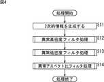
次に、図4は、図3のステップS4におけるノイズ除去処理を説明するフローチャートである。 Next, FIG. 4 is a flowchart for explaining the noise removal processing in step S4 of FIG.
例えば、画像処理部24が、所定の1フレームにおける入力部分の点情報をノイズ除去部25に供給すると処理が開始される。上述したように、入力部分の点情報には、処理対象となるフレームにおいて検出された全ての入力部分についての座標、接触面積、および形状を示す情報が含まれている。 For example, the processing is started when the
ステップS11において、ノイズ除去部25は、物体の非接触部分で検出された入力部分についての形状などの特徴を抽出するために、画像処理部24から供給される入力部分の点情報に基づいて、入力部分についての2次的情報を生成する。例えば、ノイズ除去部25は、入力部分の密度値およびアスペクト比を2次的情報として生成する。即ち、ノイズ除去部25は、入力部分の形状に基づいて入力部分に外接する矩形を求め、この外接矩形の面積に対する入力部分の面積を入力部分の密度値として算出する。また、ノイズ除去部25は、この外接矩形の縦方向と横方向の長さの比率をアスペクト比として算出する。 In step S11, the
ステップS12において、ノイズ除去部25は、ステップS11で算出した各入力部分の密度値に従って、所定の高密度閾値以上となる密度値が算出された入力部分の点情報を除去する異常高密度フィルタ処理(図5)を行う。 In step S12, the
ステップS13において、ノイズ除去部25は、ステップS11で算出した各入力部分の密度値に従って、所定の低密度閾値以下となる密度値が算出された入力部分の点情報を除去する異常低密度フィルタ処理(図6)を行う。 In step S <b> 13, the
ステップS14において、ノイズ除去部25は、ステップS11で算出した各入力部分のアスペクト比に従って、所定のアスペクト比閾値以上となるアスペクト比が算出された入力部分の点情報を除去する異常アスペクト比フィルタ処理(図7)を行う。ステップS14の処理後、処理は終了する。 In step S14, the
次に、図5乃至図7を参照して、異常高密度フィルタ処理、異常低密度フィルタ処理、および異常アスペクト比フィルタ処理について説明する。なお、ノイズ除去部25には、例えば、操作入力装置21の設計時などにおいて、ユーザの指などによる入力操作に対して正常に応答するような閾値が決定されており、それらの閾値が予め記憶されている。 Next, the abnormal high density filter processing, the abnormal low density filter processing, and the abnormal aspect ratio filter processing will be described with reference to FIGS. In the
図5は、図4のステップS12における異常高密度フィルタ処理を説明するフローチャートである。 FIG. 5 is a flowchart for explaining the abnormal high-density filter processing in step S12 of FIG.
異常高密度フィルタ処理において、ノイズ除去部25は、図4のステップS11で2次的情報が生成された点情報を、順次、対象として評価を行っており、ステップS21において、2次的情報が生成された全ての点情報を評価の対象としたか否かを判定する。 In the abnormal high density filter process, the
ステップS21において、ノイズ除去部25が、全ての点情報を評価の対象としていないと判定した場合、即ち、評価の対象とされていない点情報がまだある場合、処理はステップS22に進む。 In step S21, when the
ステップS22において、ノイズ除去部25は、評価の対象とされていない所定の点情報を処理の対象とし、評価対象の点情報の密度値が高密度閾値以上であるか否かを判定する。 In step S <b> 22, the
ステップS22において、ノイズ除去部25が、評価対象の点情報の密度値が高密度閾値以上であると判定した場合、処理はステップS23に進む。 In step S22, when the
ステップS23において、ノイズ除去部25は、ステップS22で評価対象とした点情報を除去する。即ち、高密度閾値以上となるような異常に高い密度値が算出された点情報は、ノイズ成分であると認識されて除去される。 In step S23, the
ステップS23の処理後、または、ステップS22で評価対象の点情報の密度値が高密度閾値以上でないと(高密度閾値未満であると)判定された場合、処理はステップS21に戻り、以下、同様の処理が繰り返される。 After the processing of step S23, or when it is determined in step S22 that the density value of the point information to be evaluated is not equal to or higher than the high density threshold (below the high density threshold), the processing returns to step S21, and so on. The process is repeated.
一方、ステップS21において、ノイズ除去部25が、全ての点情報を評価の対象としたと判定した場合、異常に高い密度値が算出された点情報は全て削除されており、処理は終了する。 On the other hand, if the
次に、図6は、図4のステップS13における異常低密度フィルタ処理を説明するフローチャートである。 Next, FIG. 6 is a flowchart for explaining the abnormal low density filter processing in step S13 of FIG.
ステップS31において、ノイズ除去部25は、図5のステップS21と同様に、2次的情報が生成された全ての点情報を評価の対象としたか否かを判定し、全ての点情報を評価の対象としていないと判定した場合、処理はステップS32に進む。 In step S31, as in step S21 of FIG. 5, the
ステップS32において、ノイズ除去部25は、評価の対象とされていない所定の点情報を処理の対象とし、評価対象の点情報の密度値が低密度閾値以下であるか否かを判定する。 In step S <b> 32, the
ステップS32において、ノイズ除去部25が、評価対象の点情報の密度値が低密度閾値以下であると判定した場合、処理はステップS33に進み、ノイズ除去部25は、その点情報を除去する。即ち、低密度閾値以下となるような異常に低い密度値が算出された点情報は、ノイズ成分であると認識されて除去される。 In step S32, when the
ステップS33の処理後、または、ステップS32で評価対象の点情報の密度値が低密度閾値以下でないと(低密度閾値より大であると)判定された場合、処理はステップS31に戻り、以下、同様の処理が繰り返される。 After the process of step S33, or when it is determined in step S32 that the density value of the point information to be evaluated is not less than the low density threshold (is greater than the low density threshold), the process returns to step S31. Similar processing is repeated.
一方、ステップS31において、ノイズ除去部25が、全ての点情報を評価の対象としたと判定した場合、異常に低い密度値が算出された点情報は全て削除されており、処理は終了する。 On the other hand, if the
次に、図7は、図4のステップS14における異常アスペクト比フィルタ処理を説明するフローチャートである。 Next, FIG. 7 is a flowchart for explaining the abnormal aspect ratio filter processing in step S14 of FIG.
ステップS41において、ノイズ除去部25は、図5のステップS21と同様に、2次的情報が生成された全ての点情報を評価の対象としたか否かを判定し、全ての点情報を評価の対象としていないと判定した場合、処理はステップS42に進む。 In step S41, as in step S21 of FIG. 5, the
ステップS42において、ノイズ除去部25は、評価の対象とされていない所定の点情報を処理の対象とし、評価対象の点情報のアスペクト比がアスペクト比閾値以上であるか否かを判定する。 In step S <b> 42, the
ステップS42において、ノイズ除去部25が、評価対象の点情報のアスペクト比がアスペクト比閾値以上であると判定した場合、処理はステップS43に進み、ノイズ除去部25は、その点情報を除去する。即ち、アスペクト比閾値以上となるような異常に高いアスペクト比が算出された点情報は、ノイズ成分であると認識されて除去される。 In step S42, when the
ステップS43の処理後、または、ステップS42で評価対象の点情報のアスペクト比がアスペクト比閾値以上でないと(アスペクト比閾値以上未満であると)判定された場合、処理はステップS41に戻り、以下、同様の処理が繰り返される。 After the process of step S43, or when it is determined in step S42 that the aspect ratio of the point information to be evaluated is not equal to or greater than the aspect ratio threshold (less than the aspect ratio threshold), the process returns to step S41. Similar processing is repeated.
一方、ステップS41において、ノイズ除去部25が、全ての点情報を評価の対象としたと判定した場合、異常に高いアスペクト比が算出された点情報は全て削除されており、処理は終了する。 On the other hand, if the
以上のように、ノイズ除去部25では、密度値およびアスペクト比に基づいて、ノイズ成分と認識された入力部分を除去することができる。 As described above, the
例えば、操作入力装置21は、ユーザの指により入力操作が行われることを想定して設計されており、通常、ユーザの指が接触したときの接触領域は楕円形となる。従って、例えば、想定されている楕円形よりも細長い形状が検出された入力部分は、ユーザの指による入力操作ではない、即ち、ノイズ成分であると判断することができ、ノイズ除去処理において除去される。つまり、ユーザの指による接触領域と判断できる範囲となるように、高密度閾値および低密度閾値が設定され、ユーザの指による接触領域と判断できる最も高いアスペクト比に、アスペクト比閾値が設定される。 For example, the
従って、ノイズ除去処理により、ユーザの指などによる操作入力以外で検出された入力部分の点情報を削除すること、例えば、入出力ディスプレイ22への照射光の変化によって検出された非接触部分の点情報を削除することができる。これにより、非接触部分の点情報に基づく誤動作を防止することができ、より正確な動作をすることができる。 Therefore, the point information of the input part detected by the noise removal process other than the operation input by the user's finger or the like is deleted, for example, the point of the non-contact part detected by the change of the irradiation light to the input /
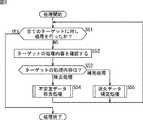
次に、図8は、図3のステップS6におけるターゲット修正処理を説明するフローチャートである。ここで、上述したように、操作入力装置21では、入出力ディスプレイ22に表示される画像の1フレームごとに処理が繰り返して行われており、現在処理の対象としているフレームを、以下、適宜、時刻tのフレームと称する。 Next, FIG. 8 is a flowchart for explaining the target correction process in step S6 of FIG. Here, as described above, in the
ステップS51において、処理選択部41は、ターゲット生成部31において生成された全てのターゲット情報を対象として処理を行ったか否かを判定する。例えば、入出力ディスプレイ22の表示画面上に複数箇所でユーザの指などが接触しているとき、ターゲット生成部31では、時刻tのフレームにおいて、それらに対応する複数のターゲットを認識し、複数のターゲット情報を生成している。従って、修正部27では、ターゲット生成部31において複数のターゲット情報が生成されているとき、それらのターゲット情報を、順次、対象として処理を行う。 In step S <b> 51, the
ステップS51において、処理選択部41が、全てのターゲット情報を対象として処理を行っていないと判定した場合、即ち、処理の対象とされていないターゲット情報がまだある場合、処理はステップS52に進む。 If the
ステップS52において、処理選択部41は、まだ処理の対象とされていないターゲット情報を処理の対象として、そのターゲット情報に記載されている処理内容を確認し、処理はステップS53に進む。 In step S52, the
例えば、時刻t−1のフレーム(1フレーム前のフレーム)に対する処理においてターゲット生成部31によりターゲットとして認識された入力部分についてのターゲット情報には、時刻t−1におけるターゲット修正処理で処理内容が記載されている。従って、処理選択部41は、記憶部44に記憶されている中間データのうちの、時刻t−1の同一のターゲットIDで識別されるターゲット情報を参照し、その記載内容を確認する。 For example, in the target information about the input part recognized as the target by the
また、処理選択部41は、ターゲット情報に処理内容が記載されていなければ、そのターゲット情報の処理内容に、除去処理を記載する。即ち、時刻t−1における処理においてターゲットとして認識されてなく、時刻tのフレームに対する処理においてターゲットとして認識された入力部分についてのターゲット情報には、処理内容が記載されていない。このため、処理選択部41は、処理内容の初期設定として除去処理を記載する。 Moreover, the
ステップS53において、処理選択部41は、ステップS52で確認(または記述)したターゲット情報の処理内容(Mode)が、除去処理(Delete Mode)および補完処理(Hold Mode)のいずれであるかを判定する。 In step S53, the
ステップS53において、処理選択部41が、ターゲット情報の処理内容が除去処理である(Mode=Delete Mode)と判定した場合、処理選択部41はターゲット情報を不安定データ除去部43に供給し、処理はステップS54に進む。ステップS54において、不安定データ除去部43は、ステップS53で処理選択部41から供給されたターゲット情報に不安定データ除去処理(図9)を施す。 In step S53, when the
一方、ステップS53において、処理選択部41が、処理の対象としたターゲットの処理内容が補完処理である(Mode=Hold Mode)と判定した場合、処理選択部41はターゲット情報を消失データ補完部42に供給し、処理はステップS55に進む。ステップS55において、消失データ補完部42は、ステップS53で処理選択部41から供給されたターゲット情報に消失データ補完処理(図10)を施す。 On the other hand, when the
ステップS54またはS55の処理後、処理はステップS51に戻り、以下、ステップS51において、全てのターゲット情報を対象として処理を行ったと判定されるまで、処理が繰り返される。 After the process of step S54 or S55, the process returns to step S51. Hereinafter, the process is repeated until it is determined in step S51 that the process has been performed on all target information.
ここで、ターゲット修正処理を繰り返す回数(即ち、全てのターゲットの個数)は、時刻t−1のフレームに対する処理において制御部28に出力したターゲット情報の個数と、時刻tのフレームに対する処理において生成部26から供給されたターゲット情報のうちの、時刻t−1のフレームに対する処理において制御部28に出力したターゲット情報に含まれるターゲットIDと重複しないものの個数とを加算したものとなる。 Here, the number of times the target correction process is repeated (that is, the number of all targets) is the number of target information output to the
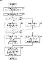
次に、図9は、図8のステップS54における不安定データ除去処理を説明するフローチャートである。 Next, FIG. 9 is a flowchart for explaining the unstable data removal processing in step S54 of FIG.
ステップS61において、不安定データ除去部43は、時刻tのフレームに対してターゲット生成部31が生成したターゲット情報を、時刻tの中間データとして記憶部44に記憶させ、処理はステップS62に進む。 In step S61, the unstable
ステップS62において、不安定データ除去部43は、時刻tの中間データの面積値Atと、時刻t−1の中間データの面積値At-1とに基づいて、次の式(1)を演算することにより、面積変化率(dA/A)を求める。なお、時刻t−1の中間データとは、時刻t−1(1サンプル前)のフレームに対してターゲット生成部31が生成し、中間データとして記憶部44に既に記憶されているターゲット情報のうちの、処理対象の中間データと同一のターゲットIDのものである。In step S62, the unstable

ステップS62の処理後、処理はステップS63に進み、不安定データ除去部43は、ステップS62で算出した面積変化率が、面積変化率閾値(Ath)より大であるか否かを判定する。 After the process of step S62, the process proceeds to step S63, and the unstable
ステップS63において、不安定データ除去部43が、面積変化率が、面積変化率閾値より大である(dA/A>Ath)と判定した場合、処理はステップS64に進む。ステップS64において、不安定データ除去部43は、処理の対象としている中間データに新規のIDを割り当て、中間データに割り当てられた新規IDの生存期間に1をセット(Life=1)する。即ち、この場合、面積変化率が大きいので、一連の操作入力ではなく、新たな操作入力と判断することができ、処理の対象としている中間データに対応するターゲットは新規に創出されたものとして処理が行われる。 If the unstable
一方、ステップS63において、不安定データ除去部43が、面積変化率が、面積変化率閾値より大でない(dA/A≦Ath)と判定した場合、処理はステップS65に進む。ステップS65において、不安定データ除去部43は、処理の対象としているターゲットデータの生存期間をインクリメント(Life++)する。即ち、この場合、面積変化率が小さいので、一連の操作入力として安定したものとして処理が行われる。 On the other hand, when the unstable
ステップS64またはS65の処理後、処理はステップS66に進み、不安定データ除去部43は、処理の対象としている中間データの生存期間が、所定の生存期間閾値(Life th)より大であるか否かを判定する。 After the process of step S64 or S65, the process proceeds to step S66, and the unstable
ステップS66において、不安定データ除去部43が、中間データの生存期間が、所定の生存期間閾値より大である(Life>Life th)と判定した場合、処理はステップS67に進む。 If the unstable
ステップS67において、不安定データ除去部43は、この中間データを出力ターゲットデータに代入する。即ち、この場合、中間データは、規定期間において面積変化が少ないので、不安定なデータではなく、ユーザの指などによる入力操作によるデータであると判断することができ、その中間データであるターゲット情報が制御部28に出力される。また、以降の処理において、同じIDの中間データの消失を防止するために、中間データの処理内容を補完処理(Mode=Hold Mode)とするとともに、中間データの補完期間に0をセット(Hold Time=0)する。 In step S67, the unstable
一方、ステップS66において、不安定データ除去部43が、ターゲット情報の生存期間が、所定の生存期間閾値より大でない(Life≦Life th)と判定した場合、処理はステップS68に進む。 On the other hand, if the unstable
ステップS68において、不安定データ除去部43は、出力ターゲットデータをクリアする。即ち、この場合、中間データは、不安定なデータであると判断することができ、その中間データであるターゲット情報は制御部28に出力されない。また、この中間データの処理内容を除去処理(Mode=Delete Mode)とするとともに、中間データの補完期間に0をセット(Hold Time=0)する。 In step S68, the unstable
ステップS67またはS68の処理後、処理はステップS69に進み、不安定データ除去部43は、時刻tの中間データを生成部26の記憶部32に記憶させ、処理は終了する。即ち、時刻tの中間データは、ターゲット生成部31が、次の時刻のフレーム(時刻t+1のフレーム)におけるターゲット情報を生成する処理で参照するためのターゲット生成用参照データとされる。 After the process of step S67 or S68, the process proceeds to step S69, where the unstable
以上のように、不安定データ除去部43では、面積変化率、および、ターゲットの生存期間に基づいて、不安定なデータを除去することができる。これにより、誤作動を防止することができる。 As described above, the unstable
次に、図10は、図8のステップS55における消失データ補完処理を説明するフローチャートである。 Next, FIG. 10 is a flowchart for explaining the lost data supplement processing in step S55 of FIG.
ステップS71において、消失データ補完部42は、時刻tのフレームに対してターゲット生成部31が生成したターゲット情報を、時刻tの中間データとして記憶部44に記憶させ、処理はステップS72に進む。 In step S71, the lost
ステップS72において、消失データ補完部42は、時刻tの中間データと、時刻t−1の出力データ(時刻t−1で出力ターゲットデータに代入した全てのターゲット情報)とを比較し、処理はステップS73に進む。 In step S72, the lost
ステップS73において、消失データ補完部42は、ステップS72で時刻tの中間データと時刻t−1の出力データとを比較した結果、ターゲットが消失したか否かを判定する。 In step S73, the lost
例えば、消失データ補完部42は、ステップS72での比較の結果、時刻t−1の出力データにおいて処理内容が補完処理(Mode=Hold Mode)であるターゲット情報であり、かつ、時刻tの中間データにおいて存在しないターゲットID(消失したターゲットID)を含むターゲット情報が検出されている場合、この条件に合致するターゲット情報のターゲットは消失したものとする。 For example, as a result of the comparison in step S72, the lost
一方、消失データ補完部42は、時刻tの中間データのターゲット情報に含まれるターゲットIDが、時刻t−1の出力データにおけるターゲット情報に含まれるターゲットIDと一致する場合、ターゲットは消失していないと判定する。 On the other hand, when the target ID included in the target information of the intermediate data at time t matches the target ID included in the target information in the output data at time t−1, the lost
ステップS73において、消失データ補完部42が、ターゲットが消失した判定した場合、処理はステップS74に進む。 In step S73, when the lost
ステップS74において、消失データ補完部42は、消失したと判定されたターゲットについての時刻t−1の出力ターゲットデータを参照し、その補完期間(Hold Time)が、所定の補完期間閾値(Hth)より大であるか否かを判定する。 In step S74, the lost
ステップS74において、消失データ補完部42が、消失したと判定されたターゲットについての時刻t−1の出力ターゲットデータの補完期間が、所定の補完期間閾値より大である(Hold Time>Hth)と判定した場合、処理はステップS75に進む。 In step S74, the lost
ステップS75において、消失データ補完部42は、中間データの生存期間に1をセット(Life=1)し、処理はステップS76に進む。 In step S75, the lost
ステップS76において、消失データ補完部42は、出力ターゲットデータをクリアする。即ち、この場合、消失したと判定されたターゲットの中間データは制御部28に出力されない。また、消失データ補完部42は、この中間データの処理内容を除去処理(Mode=Delete Mode)とするとともに、中間データの補完期間に0をセット(Hold Time=0)する。 In step S76, the lost
ステップS76の処理後、処理はステップS77に進み、消失データ補完部42は、時刻tの出力ターゲットデータをターゲット生成用参照データとして、生成部26の記憶部32に記憶させ、処理は終了する。即ち、時刻tの出力ターゲットデータは、ターゲット生成部31が、次のフレーム(時刻t+1のフレーム)に対してターゲット情報を生成する処理で参照するためのターゲット生成用参照データとされる。この場合、時刻tの出力ターゲットデータはクリアされており、ターゲットが消失した(例えば、ユーザの指などが入出力ディスプレイ22の表示画面から離された)ものとして以降の処理が行われる。 After the process of step S76, the process proceeds to step S77, and the lost
一方、ステップS74において、消失データ補完部42が、消失したと判定されたターゲットについての時刻t−1の出力ターゲットデータの補完期間が、所定の補完期間閾値より大でない(Hold Time≦Hth)と判定した場合、処理はステップS78に進む。 On the other hand, in step S74, the lost
ステップS78において、消失データ補完部42は、中間データの生存期間をインクリメント(Life++)し、処理はステップS79に進む。 In step S78, the lost
ステップS79において、消失データ補完部42は、出力ターゲットデータに、時刻t−1の出力データ(即ち、時刻t−1で出力ターゲットデータに代入されたターゲット情報のうちの、消失したと判定されたターゲットのターゲット情報)をコピーする。即ち、この場合、消失したと判定されたターゲットについては、1フレーム前のターゲット情報と同一のターゲット情報が出力される。また、消失データ補完部42は、この中間データの処理内容を補完処理(Mode=Hold Mode)とするとともに、中間データの補完期間をインクリメント(Hold Time++)する。 In step S79, the erasure
ステップS79の処理後、処理はステップS77に進み、消失データ補完部42は、時刻tの出力ターゲットデータをターゲット生成用参照データとして記憶部32に記憶させ、処理は終了する。この場合、時刻tの出力ターゲットデータは、時刻t−1の出力データがコピーされたものであり、消失したターゲットが補完されて以降の処理が行われる。 After the process of step S79, the process proceeds to step S77, and the lost
一方、ステップS73において、消失データ補完部42が、ターゲットが消失していないと判定した場合、処理はステップS80に進む。 On the other hand, when the lost
ステップS80において、消失データ補完部42は、時刻tの中間データの生存期間をインクリメント(Life++)し、処理はステップS81に進む。 In step S80, the lost
ステップS81において、消失データ補完部42は、中間データを出力ターゲットデータに代入する。即ち、この場合、ターゲットは消失していないので、中間データが制御部28に出力される。また、消失データ補完部42は、この中間データの処理内容を補完処理(Mode=Hold Mode)とするとともに、中間データの補完期間に0をセット(Hold Time=0)する。 In step S81, the lost
ステップS81の処理後、処理はステップS77に進み、消失データ補完部42は、時刻tの出力ターゲットデータをターゲット生成用参照データとして記憶部32に記憶させ、処理は終了する。この場合、ターゲットは消失していないので、検出されたターゲットを用いて以降の処理が行われる。 After the process of step S81, the process proceeds to step S77, and the lost
以上のように、消失データ補完部42では、ターゲットが消失したときに、補完期間が所定の閾値以下の短いものであれば、一時的にターゲットが消失したものと判断できるので、そのターゲットを、1フレーム前の出力データで補完する処理が行われる。これにより、ターゲットが一時的に消失することにより、例えば、消失の前後で異なる操作と判断されることによる誤作動を防止することができる。即ち、一時的な消失であれば、一連の入力とみなして処理を行うことができる。 As described above, in the lost
次に、図11乃至図13を参照して、修正部27の動作例を説明する。なお、この動作例においては、生存期間閾値(Life th)が1に設定されているとともに、補完期間閾値(Hth)が1に設定されている。 Next, an operation example of the
図11乃至図13では、横方向がサンプリング時間を表し、左側から右側に向かって時刻tの経過が示されている。また、図11乃至図13では、縦方向が処理の流れを表している。即ち、上側から下側に向かって、ターゲット生成部31に入力される入力部分の点情報、ターゲット生成部31において生成されたターゲット情報、記憶部44に記憶される中間データ、制御部28に出力される出力ターゲットデータ、および、記憶部32に記憶されるターゲット生成用参照データを表している。 11 to 13, the horizontal direction represents the sampling time, and the passage of time t is shown from the left side to the right side. In FIGS. 11 to 13, the vertical direction represents the flow of processing. That is, from the upper side to the lower side, point information of the input part input to the
図11は、修正部27の不安定データ除去部43における不安定データ除去処理による効果が示されている。 FIG. 11 shows the effect of the unstable data removal processing in the unstable
例えば、ターゲット生成部31は、時刻t+1においてターゲットを新たに検出し、そのターゲットにターゲットID#1を割り振るとともに、生存期間に1をセット(Life=1)し、補完期間に0をセット(Hold Time=0)する。また、処理選択部41は、処理内容の初期設定として除去処理を記載する(図8のステップS52の処理)。 For example, the
そして、時刻t+2において、連続的なターゲットが検出され、ターゲット生成部31は、そのターゲットに時刻t+1で検出したターゲットID#1を割り振る。しかしながら、時刻t+2で検出されたターゲットは、時刻t+1で検出されたターゲットID#1のターゲットの面積よりも急激に大きな面積に変化している。例えば、その面積変化率が、面積変化率閾値より大である(dA/A>Ath)場合、不安定データ除去部43は、時刻t+2で検出されたターゲットに新規ID(ターゲットID#2)を割り当てる(図9のステップS64の処理)。さらに、生存期間が1以下である(Life≦Life th)であるので、この場合、出力ターゲットデータはクリアされ、ターゲットID#2のターゲットは出力されない(図9のステップS68の処理)。 Then, at time t + 2, a continuous target is detected, and the
その後、時刻t+3において、2つのターゲットが検出され、ターゲット生成部31は、その一方にターゲットID#2を割り当てる。しかしながら、時刻t+3におけるターゲットID#2のターゲットの面積は、時刻t+2におけるターゲットID#2のターゲットの面積よりも急激に小さな面積に変化している。従って、不安定データ除去部43は、そのターゲットに新規ID(ターゲットID#4)を割り当て、出力ターゲットデータをクリアする。 Thereafter, at
このように、不安定データ除去部43が、面積変化率が大きいターゲットは不安定なターゲットとして、出力されないように不安定データ処理を行うので、ユーザによる入力操作以外の、不安定なターゲットに基づく誤動作を防止することができる。 As described above, the unstable
図12は、修正部27の消失データ補完部42における消失データ補完処理による効果が示されている。 FIG. 12 shows the effect of the lost data complementing process in the lost
例えば、ターゲット生成部31は、時刻t+1においてターゲットを新たに検出し、そのターゲットにターゲットID#5を割り振るとともに、生存期間に1をセット(Life=1)し、補完期間に0をセット(Hold Time=0)する。また、処理選択部41は、処理内容の初期設定として除去処理(Mode=Delete Mode)を記載する(図8のステップS52の処理)。 For example, the
そして、時刻t+2において、連続的なターゲットが検出され、ターゲット生成部31は、そのターゲットに時刻t+1で検出したターゲットID#5を割り振る。そして、処理内容が除去処理(Mode=Delete Mode)であるので、不安定データ除去部43にターゲット情報が供給されるが、時刻t+2で検出されたターゲットは、時刻t+1で検出されたターゲットID#5のターゲットの面積と同等であるので、その中間データの生存期間がインクリメントされる(図9のステップS65の処理)。 Then, at time t + 2, a continuous target is detected, and the
さらに、不安定データ除去部43は、生存期間が1以上である(Life>Life th)ので、その中間データを出力ターゲットデータに代入するとともに、処理内容を補完処理(Mode=Hold Mode)にして、補完期間に0をセット(Hold Time=0)する。従って、この場合、ターゲットID#5のターゲット情報が出力される。 Further, the unstable
その後、時刻t+3で、ターゲットが検出されなくても、ターゲットID#5の中間データの処理内容が補完処理であるので、消失データ補完部42において消失データ補完処理が行われ、1フレーム前のターゲット情報と同一のターゲット情報が出力される(図10のステップS79の処理)。 After that, even if no target is detected at
このように、安定的なターゲットが一時的に消失しても、そのターゲットを補完することで、一時的な消失の前後で、異なるターゲットIDが割り振られることなく、即ち、一連の操作入力として同一のIDを割り振ることができる。従って、異なる2回の操作が行われたと判断されることによる誤動作が発生することを回避することができる。 In this way, even if a stable target temporarily disappears, by complementing the target, different target IDs are not assigned before and after the temporary disappearance, that is, as a series of operation inputs. IDs can be assigned. Therefore, it is possible to avoid a malfunction caused by determining that two different operations have been performed.
図13は、修正部27の不安定データ除去部43における不安定データ除去処理による効果が示されている。なお、図14では、ユーザの指などによる入力操作に基づいて検出されるターゲットと同時に、不安定なターゲットが発生したときの動作例が示されている。 FIG. 13 shows the effect of the unstable data removal processing in the unstable
即ち、時刻t+1から時刻t+3までの間、ターゲットID#6のターゲットは安定している入力部分として検出されているが、時刻t+2で検出されているターゲットID#7のターゲットは、一時的に発生している不安定なターゲットであるため除去されている。 That is, from time t + 1 to
このように、各ターゲットを識別するターゲットIDを利用して、ターゲットごとに独立して不安定データ除去処理と消失データ補完処理とに処理が振り分けられるので、ユーザによる入力操作中に不安定なターゲットが発生しても、操作入力によるターゲットに影響を与えずに、不安定なターゲットのみを除去することができる。 In this way, the target ID for identifying each target is used to distribute the process to the unstable data removal process and the lost data supplement process independently for each target. Even if this occurs, only the unstable target can be removed without affecting the target by the operation input.
以上のように、不安定データ除去処理と消失データ補完処理とを適切に選択して処理を行うことで、外部から入力があった複数の点の点情報を、入出力ディスプレイ22を備えた操作入力装置21において実行される上位のアプリケーションにおいて容易に取り扱うことができる。また、入出力ディスプレイ22への照射光の時間的または空間的な変動により発生するノイズ成分を除去することで、指などの非完全反射物による操作時のターゲットの消失を防止することができ、上位のアプリケーションで誤動作が発生することを防止することができる。 As described above, by appropriately selecting the unstable data removal process and the lost data complementing process and performing the process, the point information of a plurality of points input from the outside is operated by the operation provided with the input /
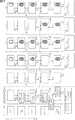
次に、図14は、本発明を適用した操作入力装置の第2の実施の形態の構成例を示すブロック図である。 Next, FIG. 14 is a block diagram showing a configuration example of the second embodiment of the operation input device to which the present invention is applied.
図14において、操作入力装置51は、外光センサ52、選択処理部53、入出力ディスプレイ22、受光信号処理部23、画像処理部24、ノイズ除去部25、生成部26、修正部27、および制御部28を備えて構成される。なお、図14では、図2の操作入力装置21と共通する部分については、同一の符号を付してあり、以下では、その説明は、適宜省略する。 In FIG. 14, the
即ち、図14の操作入力装置51は、入出力ディスプレイ22、受光信号処理部23、画像処理部24、ノイズ除去部25、生成部26、修正部27、および制御部28を備える点で、図2の操作入力装置21と共通する。但し、図14の操作入力装置51は、外光センサ52および選択処理部53を備える点で、図2の操作入力装置21と相違する。 That is, the
外光センサ52は、例えば、入出力ディスプレイ22に照射される外光の状態(例えば、外光の照度や、外光のスペクトル、外光の照射方向など)を検出し、外光の状態を示す外光情報を取得して、その外光情報を処理選択部41および53に供給する。 The external
選択処理部53は、外光センサ52から供給される外光情報に基づいて、ノイズ除去部25にノイズ除去処理を行わせか否かを選択する。例えば、選択処理部53は、入出力ディスプレイ22に照射されている外光が、画像処理部24において検出される入力部分の点情報にノイズ成分が発生させるようなものである場合、入力部分の点情報をノイズ除去部25に供給し、ノイズ除去処理を行わせる。一方、選択処理部53は、入出力ディスプレイ22に照射されている外光が、画像処理部24において検出される入力部分の点情報にノイズ成分が発生させるようなものでない場合、入力部分の点情報を生成部26に供給する。この場合、ノイズ除去部25によるノイズ除去処理は行われない。 The
このように選択処理部53がノイズ除去部25にノイズ除去処理を行わせか否かを選択することで、ノイズ成分が発生するような外光条件でないとき、ノイズ除去処理をスキップすることにより、処理速度を向上させることができる。 By selecting whether or not the
また、操作入力装置51では、修正部27の処理選択部41に、外光センサ52から外光情報が供給され、修正部27では、その外光情報に基づいたターゲット修正処理が実行される。 In the
例えば、入出力ディスプレイ22に照射されている外光の状態によっては、ターゲットの消失が発生せずに不安定なターゲットが発生するような外光条件や、不安定なターゲットが発生せずにターゲットの消失が発生するような外光条件がある。また、不安定なターゲットが発生するとともに、ターゲットの消失が発生するような外光条件や、不安定なターゲットが発生せず、ターゲットの消失が発生しないような外光条件がある。従って、処理選択部41は、外光センサ52から供給される外光情報に基づき、入出力ディスプレイ22に照射されている外光の状態に応じて、ターゲット修正処理において実行する処理を決定する。 For example, depending on the state of the external light applied to the input /
即ち、図15は、図14の操作入力装置51において実行されるターゲット修正処理を説明するフローチャートである。 That is, FIG. 15 is a flowchart for explaining target correction processing executed in the
ステップS101において、外光センサ52は、入出力ディスプレイ22に照射される外光の状態を検出して外光情報を取得し、修正部27の処理選択部41に供給する。 In step S <b> 101, the external
ステップS102において、処理選択部41は、ステップS101で外光センサ52から供給された外光情報に基づいて、不安定なターゲットが発生するような外光条件であるか否かを判定する。 In step S102, the
ステップS102において、処理選択部41が、不安定なターゲットが発生するような外光条件であると判定した場合、処理はステップS103に進み、処理選択部41は、ターゲットの消失が発生するような外光条件であるか否かを判定する。 In step S102, when the
ステップS103において、処理選択部41が、ターゲットの消失が発生するような外光条件であると判定した場合、処理はステップS104に進む。即ち、この場合、不安定なターゲットが発生するともに、ターゲットの消失が発生するような外光条件であるので、不安定データ除去処理および消失データ補完処理のいずれかの処理が選択的に行われる。 In step S103, when the
ステップS104乃至S108において、図8のステップS51乃至S55と同様に、全てのターゲットに対して、不安定データ除去処理および消失データ補完処理のうちの一方の処理が施され、処理は終了する。 In steps S104 to S108, as in steps S51 to S55 of FIG. 8, one of the unstable data removal process and the lost data complement process is performed on all targets, and the process ends.
一方、ステップS103において、処理選択部41が、ターゲットの消失が発生するような外光条件でないと判定した場合、処理はステップS109に進む。即ち、この場合、入出力ディスプレイ22に照射されている外光の状態は、ターゲットの消失は発生せずに、不安定なターゲットが発生する外光条件となっている。 On the other hand, when the
ステップS109において、処理選択部41は、全てのターゲット情報を不安定データ除去部43に供給し、不安定データ除去部43が、全てのターゲットに対して不安定データ除去処理を施し、処理は終了する。 In step S109, the
一方、ステップS102において、処理選択部41が、不安定なターゲットが発生するような外光条件でないと判定した場合、処理はステップS110に進み、処理選択部41は、ターゲットの消失が発生するような外光条件であるか否かを判定する。 On the other hand, if the
ステップS110において、処理選択部41が、ターゲットの消失が発生するような外光条件であると判定した場合、処理はステップS111に進む。即ち、この場合、入出力ディスプレイ22に照射されている外光の状態は、不安定なターゲットが発生せずに、ターゲットの消失が発生する外光条件となっている。 In step S110, when the
ステップS111において、処理選択部41は、全てのターゲット情報を消失データ補完部42に供給し、消失データ補完部42が、全てのターゲットに対して消失データ補完処理を施し、処理は終了する。 In step S111, the
一方、ステップS110において、処理選択部41が、ターゲットの消失が発生するような外光条件でないと判定した場合、不安定データ除去処理および消失データ補完処理は行われずに、処理は終了する。即ち、この場合、入出力ディスプレイ22に照射されている外光の状態は、不安定なターゲットが発生せずに、ターゲットの消失も発生しない外光条件となっている。 On the other hand, in step S110, when the
以上のように、外光条件に従って処理を選択するので、操作入力装置51の使用環境の照度などに合わせて最適な処理を行うことができる。例えば、ターゲットの消失が発生するような外光条件や、不安定なターゲットが発生するような外光条件であれば、処理性能が向上するように(例えば、誤作動が発生せずに正確に動作するように)処理が選択される。また、ターゲットの消失の発生も、不安定なターゲットの発生もないよう外光条件であれば、処理速度が向上するように処理が選択される。これにより、より効果的に誤動作を防止する効果を得ることができる。 As described above, since the process is selected according to the external light condition, it is possible to perform the optimal process according to the illuminance of the usage environment of the
また、消失データ補完部42または不安定データ除去部43は、外光条件に応じて、それぞれの処理に用いる閾値を最適化することができる。 Further, the lost
例えば、ターゲットの消失が発生しやすい外光条件である場合、消失データ補完部42は、補完期間閾値(Hth)を、通常よりも大きな値に設定することで、ターゲットが消失し難くなるようにすることができる。また、不安定なターゲットが発生しやすい外光条件である場合、不安定データ除去部43は、生存期間閾値(Life th)を、通常よりも大きな値に設定することで、不安定なターゲットを除去し易くすることができる。 For example, in the case of an external light condition in which the loss of the target is likely to occur, the lost
次に、図16は、本発明を適用した操作入力装置の第3の実施の形態の構成例を示すブロック図である。 Next, FIG. 16 is a block diagram showing a configuration example of the third embodiment of the operation input device to which the present invention is applied.
図16において、操作入力装置61は、制御パラメータ調整部62、ターゲット修正部63、外光センサ52、選択処理部53、入出力ディスプレイ22、受光信号処理部23、画像処理部24、ノイズ除去部25、生成部26、修正部27、および制御部28を備えて構成される。なお、図16では、図14の操作入力装置51と共通する部分については、同一の符号を付してあり、以下では、その説明は、適宜省略する。 In FIG. 16, an
即ち、図16の操作入力装置61は、外光センサ52、選択処理部53、入出力ディスプレイ22、受光信号処理部23、画像処理部24、ノイズ除去部25、生成部26、修正部27、および制御部28を備える点で、図14の操作入力装置51と共通する。但し、図16の操作入力装置61は、制御パラメータ調整部62およびターゲット修正部63を備える点で、図14の操作入力装置51と相違する。 16 includes an external
制御パラメータ調整部62には、入出力ディスプレイ22に照射される外光の状態を示す外光情報が外光センサ52から供給される。制御パラメータ調整部62は、外光の照度に基づいて、入出力ディスプレイ22の表示画面における発光素子の発光強度(Power)や、受光信号処理部23における信号レベル下限閾値(Signal Th)を調整する。また、制御パラメータ調整部62は、外光の照度に基づいて、画像処理部24における面積上限閾値(Amax)および面積下限閾値(Amin)を調整する。 External light information indicating the state of external light applied to the input /
ターゲット修正部63には、修正部27の消失データ補完部42または不安定データ除去部43から修正されたターゲット情報が供給されるとともに、外光センサ52から外光情報が供給される。ターゲット修正部63は、ターゲット情報に含まれるターゲットの面積値を、外光センサ52からの外光情報に基づいて求められるゲインで増幅し、その処理が施されたターゲット情報を制御部28に供給する。 The target correction unit 63 is supplied with the target information corrected from the lost
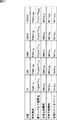
例えば、制御パラメータ調整部62およびターゲット修正部63は、図17に示すような、代表照度ごとに予め設定された各パラメータの設定値を登録したテーブル(のうちのそれぞれ必要な部分)を記憶することができる。そして、制御パラメータ調整部62およびターゲット修正部63は、外光センサ52から供給される外光情報の照度に応じて、図17のテーブルを参照し、各パラメータを決定することができる。 For example, the control
図17のテーブルでは、代表照度として、10,100,1000,10000,100000が登録されており、代表照度10に対応付けて、発光強度Power10、信号レベル下限閾値Signal Th10、面積上限閾値Amax10、面積下限閾値Amin10、およびゲインGain10が登録されている。また、同様に、代表照度100〜100000に対応付けて、発光強度Power100〜Power100000、信号レベル下限閾値Signal Th100〜Signal Th100000、面積上限閾値Amax100〜Amax100000、面積下限閾値Amin100〜Amin100000、およびゲインGain100〜Gain100000がそれぞれ登録されている。In the table of FIG. 17, 10, 100, 1000, 10000, and 100,000 are registered as representative illuminances, and the emission intensity Power10 , signal level lower limit threshold Signal Th10 , area upper limit threshold Amax10 , An area lower limit threshold Amin10 and a gain Gain10 are registered. Similarly, emission intensity Power100 to Power100000 , signal level lower limit threshold Signal Th100 to Signal Th100000 , area upper limit threshold Amax100 to Amax100000 , area lower limit threshold Amin100 to Amin100000 and gains Gain100 to Gain100000 are registered respectively.
ここで、制御パラメータ調整部62が、外光センサ52からの外光情報の照度値をLとしたときの発光強度PowerLを算出する例について説明する。例えば、代表照度のうちの、照度値L以下で最大のものをLaとし、照度値L以上で最小のものをLbとする。このとき、制御パラメータ調整部62は、図17のテーブルを参照し、代表照度Laに対応付けられている発光強度をPoweraとし、代表照度Lbに対応付けられている発光強度をPowerbとする。Here, an example will be described in which the control
そして、制御パラメータ調整部62は、次の式(2)を演算することにより、発光強度PowerLを求める。Then, the control
なお、発光強度PowerL以外のパラメータ、即ち、信号レベル下限閾値Signal ThL、面積上限閾値AmaxL、面積下限閾値AminL、およびゲインGainLについても、式(2)に基づいて、発光強度PowerLと同様に算出することができる。Note that the parameters other than the emission intensity PowerL , that is, the signal level lower limit threshold Signal ThL , the area upper limit threshold AmaxL , the area lower limit threshold AminL , and the gain GainL are also calculated based on the equation (2). It can be calculated in the same way asL.
また、テーブルに登録された代表照度の数が十分に多い場合には、上述の式(2)を簡易化した次の式(3)を用いて、各パラメータを算出することができる。 When the number of representative illuminances registered in the table is sufficiently large, each parameter can be calculated using the following equation (3) obtained by simplifying the above equation (2).
以上のように、図16の操作入力装置61では、外光センサ52の出力に基づいてパラメータを調整するので、例えば、高照度環境下において検出率の低下を防止することができる。 As described above, the
即ち、従来の入出力パネルでは、野外などの高照度環境下では、指などの非完全反射物下の光センサの信号強度は、透過光の影響を受けて、入力として認識される光センサの個数が、屋内などの低照度環境下よりも少なくなる。例えば、指のような断面が楕円形の形状となる非完全反射物の場合、低照度環境下では接触面と非接触面の境界周辺の光センサの信号強度は急峻に変化するが、高照度環境下では接触面と非接触面の境界周辺の光センサの信号強度は透過光の影響によりなだらかに変化する。このため、受信信号処理および画像処理において一定の閾値を用いて入力認識を行うと、照度によって入力光を受光していると認識される光センサの個数が異なり、高照度ほど点情報の面積が小さくなる。 That is, in a conventional input / output panel, the signal intensity of a light sensor under a non-perfect reflection object such as a finger is influenced by transmitted light and is recognized as an input under a high illumination environment such as outdoors. The number is less than in low-light environments such as indoors. For example, in the case of a non-perfect reflector that has an elliptical cross section like a finger, the signal intensity of the optical sensor around the boundary between the contact surface and the non-contact surface changes sharply in a low illumination environment, but the high illumination Under the environment, the signal intensity of the optical sensor around the boundary between the contact surface and the non-contact surface changes gently due to the influence of transmitted light. For this reason, when input recognition is performed using a certain threshold in received signal processing and image processing, the number of photosensors recognized as receiving input light differs depending on the illuminance, and the area of the point information increases as the illuminance increases. Get smaller.
さらに、ノイズ除去のために一定の面積値以下の点情報を除去する処理が行われると、点情報が除去される可能性がある。その結果、野外などの高照度環境下での指などの非完全反射物による入力操作は、低照度での操作と比較し、入力対象として認識される光センサの個数が減少し、面積値を用いたノイズ除去処理によって検出率が低下し、操作性が低下することがある。 Furthermore, when the process of removing point information below a certain area value for noise removal is performed, the point information may be removed. As a result, input operations with non-completely reflecting objects such as fingers in high-light environments such as outdoors reduce the number of photosensors that are recognized as input targets and reduce the area value compared to operations with low illumination. The noise removal processing used may reduce the detection rate and may reduce operability.
これに対し、操作入力装置61では、たとえば、ターゲット出力時の面積値を、外光条件に応じたゲインで増幅することで、周囲の環境光によらず同一の入力対象であれば、同一の面積値のターゲットを生成することができる。従って、高照度環境下と低照度環境下とで、ターゲットの面積を一定にすることができるので、上述したような検出率が低下することが回避され、その結果、操作性を維持することができる。即ち、外光条件による検出率の低下を防止する効果を得ることができる。 On the other hand, in the
さらに、操作入力装置61では、上位アプリケーションでターゲットの面積を利用した処理、例えば、ユーザが指を強く押し当てることによる接触面積の増加を利用した処理などにおいて、上述したような外光条件によって挙動が変化することが回避されるので、そのような処理を正確に行うことができる。 Furthermore, in the
なお、図14の操作入力装置51において、外光センサ52として、外光の状態を検出するための専用のセンサを設ける他、例えば、入出力ディスプレイ22に配置されている複数の光センサ22Aの一部を利用することができる。このように、光センサ22Aの一部を外光の状態を検出するセンサとして利用する場合、操作入力装置51を構成するシステムとして新たなデバイスを追加することなく外光の状態を用いた制御を行うことができる。また、図16の操作入力装置61においても同様である。 In the
上述した一連の処理は、ハードウエアにより実行することもできるし、ソフトウエアにより実行することもできる。一連の処理をソフトウエアにより実行する場合には、そのソフトウエアを構成するプログラムが、専用のハードウエアに組み込まれているコンピュータ、または、各種のプログラムをインストールすることで、各種の機能を実行することが可能な、例えば汎用のパーソナルコンピュータなどに、プログラム記録媒体からインストールされる。 The series of processes described above can be executed by hardware or can be executed by software. When a series of processing is executed by software, a program constituting the software executes various functions by installing a computer incorporated in dedicated hardware or various programs. For example, it is installed from a program recording medium in a general-purpose personal computer or the like.
図18は、上述した一連の処理をプログラムにより実行するコンピュータのハードウエアの構成例を示すブロック図である。 FIG. 18 is a block diagram illustrating an example of a hardware configuration of a computer that executes the above-described series of processes using a program.
コンピュータにおいて、CPU(Central Processing Unit)101,ROM(Read Only Memory)102,RAM(Random Access Memory)103は、バス104により相互に接続されている。 In a computer, a CPU (Central Processing Unit) 101, a ROM (Read Only Memory) 102, and a RAM (Random Access Memory) 103 are connected to each other via a
バス104には、さらに、入出力インタフェース105が接続されている。入出力インタフェース105には、キーボード、マウス、マイクロホンなどよりなる入力部106、ディスプレイ、スピーカなどよりなる出力部107、ハードディスクや不揮発性のメモリなどよりなる記憶部108、ネットワークインタフェースなどよりなる通信部109、磁気ディスク、光ディスク、光磁気ディスク、或いは半導体メモリなどのリムーバブルメディア111を駆動するドライブ110が接続されている。 An input /
以上のように構成されるコンピュータでは、CPU101が、例えば、記憶部108に記憶されているプログラムを、入出力インタフェース105及びバス104を介して、RAM103にロードして実行することにより、上述した一連の処理が行われる。 In the computer configured as described above, the
コンピュータ(CPU101)が実行するプログラムは、例えば、磁気ディスク(フレキシブルディスクを含む)、光ディスク(CD-ROM(Compact Disc-Read Only Memory),DVD(Digital Versatile Disc)等)、光磁気ディスク、もしくは半導体メモリなどよりなるパッケージメディアであるリムーバブルメディア111に記録して、あるいは、ローカルエリアネットワーク、インタネット、デジタル衛星放送といった、有線または無線の伝送媒体を介して提供される。 The program executed by the computer (CPU 101) is, for example, a magnetic disk (including a flexible disk), an optical disk (CD-ROM (Compact Disc-Read Only Memory), DVD (Digital Versatile Disc), etc.), a magneto-optical disk, or a semiconductor. The program is recorded on a
そして、プログラムは、リムーバブルメディア111をドライブ110に装着することにより、入出力インタフェース105を介して、記憶部108にインストールすることができる。また、プログラムは、有線または無線の伝送媒体を介して、通信部109で受信し、記憶部108にインストールすることができる。その他、プログラムは、ROM102や記憶部108に、あらかじめインストールしておくことができる。 The program can be installed in the
なお、コンピュータが実行するプログラムは、必ずしもフローチャートとして記載された順序に沿って時系列に処理する必要はなく、並列的あるいは個別に実行される処理(例えば、並列処理あるいはオブジェクトによる処理)も含むものである。また、プログラムは、1のCPUにより処理されるものであっても良いし、複数のCPUによって分散処理されるものであっても良い。 Note that the program executed by the computer does not necessarily have to be processed in chronological order according to the order described in the flowchart, and includes processing executed in parallel or individually (for example, parallel processing or object processing). . The program may be processed by one CPU, or may be distributedly processed by a plurality of CPUs.
なお、本発明の実施の形態は、上述した実施の形態に限定されるものではなく、本発明の要旨を逸脱しない範囲において種々の変更が可能である。 The embodiment of the present invention is not limited to the above-described embodiment, and various modifications can be made without departing from the gist of the present invention.
21 操作入力装置, 22 入出力ディスプレイ, 22A 光センサ, 23 受光信号処理部, 24 画像処理部, 25 ノイズ除去部, 26 生成部, 27 修正部, 28 制御部, 31 ターゲット生成部, 32 記憶部, 41 処理選択部, 42 消失データ補完部, 43 不安定データ除去部, 44 記憶部, 51 操作入力装置, 52 外光センサ, 53 選択処理部, 61 操作入力装置, 62 制御パラメータ調整部, 63 ターゲット修正部 21 operation input device, 22 input / output display, 22A optical sensor, 23 received light signal processing unit, 24 image processing unit, 25 noise removal unit, 26 generation unit, 27 correction unit, 28 control unit, 31 target generation unit, 32 storage unit , 41 processing selection unit, 42 lost data complementing unit, 43 unstable data removal unit, 44 storage unit, 51 operation input device, 52 external light sensor, 53 selection processing unit, 61 operation input device, 62 control parameter adjustment unit, 63 Target correction section
Claims (11)
Translated fromJapanese外部から入力があった入力部分の時間的若しくは空間的な位置関係に基づいて、一連の入力を表すターゲットの情報を生成するターゲット生成手段と、
前記ターゲット生成手段により生成されたターゲットが一時的に消失したときに、消失した前記ターゲットを補完する消失データ補完手段と、
前記ターゲット生成手段により不安定なターゲットが生成されたときに、不安定な前記ターゲットを除去する不安定データ除去手段と、
前記消失データ補完手段による処理と、前記不安定データ除去手段による処理とのいずれかを選択する処理選択手段
を備える操作入力装置。Input / output means for detecting light corresponding to a plurality of operation inputs to the display screen from the outside with respect to the display screen for displaying an image;
Target generation means for generating target information representing a series of inputs based on a temporal or spatial positional relationship of an input portion that has been input from the outside;
When the target generated by the target generation means temporarily disappears, lost data complementing means for complementing the lost target;
Unstable data removal means for removing the unstable target when an unstable target is generated by the target generation means;
An operation input device comprising: a process selection unit that selects one of a process by the lost data complementing unit and a process by the unstable data removing unit.
をさらに備える請求項1に記載の操作入力装置。The feature of the shape of the input portion based on the detection of the light by the input / output means is extracted, the input portion having the shape having an abnormal feature is removed, and the input portion other than the shape having the abnormal feature is sent to the target generation means. The operation input device according to claim 1, further comprising a noise removing unit to be supplied.
前記ターゲット生成手段により生成されたターゲットの情報を、次のフレームに対する処理で参照する中間データとして記憶する記憶手段をさらに備え、
前記処理選択手段は、前記記憶手段に記憶されている前記中間データに基づいて、処理の対象としているターゲットに対する処理を選択する
請求項1に記載の操作入力装置。The process is repeated for each frame of the image displayed on the display screen of the input / output means,
Storage means for storing target information generated by the target generation means as intermediate data to be referred to in processing for the next frame;
The operation input device according to claim 1, wherein the process selection unit selects a process for a target to be processed based on the intermediate data stored in the storage unit.
請求項3に記載の操作入力装置。When the processing selection means does not exist in the intermediate data stored in the storage means corresponding to the target to be processed, processing by the unstable data removal means for the target to be processed The operation input device according to claim 3, wherein the operation input device is selected.
前記処理選択手段は、前記生存期間の長さが所定の閾値以上である場合、前記ターゲットの次のフレームにおける処理を、前記消失データ補完手段によるものと設定する
請求項1に記載の操作入力装置。In the intermediate data, a lifetime that represents a period after target information corresponding to the intermediate data is generated by the target generation unit is set,
2. The operation input device according to claim 1, wherein when the length of the lifetime is equal to or greater than a predetermined threshold, the process selection unit sets the process in the next frame of the target to be performed by the lost data complementing unit. .
前記処理選択手段は、前記補完期間の長さが所定の閾値より大である場合、前記ターゲットの次のフレームにおける処理を、前記不安定データ除去手段によるものと設定する
請求項1に記載の操作入力装置。In the intermediate data, a complementing period representing a period in which complementation by the lost data complementing unit is performed after the target corresponding to the intermediate data disappears is set,
2. The operation according to claim 1, wherein when the length of the complement period is greater than a predetermined threshold, the processing selection unit sets the processing in the next frame of the target to be performed by the unstable data removing unit. Input device.
前記処理選択手段は、前記生存期間の長さ、および、前記補完期間の長さに基づいて、処理の対象としている前記ターゲットの次のフレームにおける処理を、前記消失データ補完手段による処理と、前記不安定データ除去手段による処理とのいずれにするか選択する
請求項1に記載の操作入力装置。The intermediate data includes a lifetime that represents a period after the target information corresponding to the intermediate data is generated by the target generation unit, and the lost data complementing unit after the target corresponding to the intermediate data has disappeared. And a completion period that represents the period of completion.
The processing selection means, based on the length of the survival period and the length of the complement period, the processing in the next frame of the target to be processed, processing by the lost data complement means, The operation input device according to claim 1, wherein the operation input device is selected to be performed by unstable data removing means.
請求項1に記載の操作入力装置。The unstable data removal unit performs processing as a new target when the target to be processed is an area change equal to or greater than a predetermined threshold based on an area change from intermediate data one frame before. The operation input device according to 1.
前記処理選択手段は、前記外光検出手段により検出された外光の状態に基づいて、前記消失データ補完手段による処理と、前記不安定データ除去手段による処理とのいずれかを選択する
請求項1に記載の操作入力装置。Further comprising external light detection means for detecting the state of external light applied to the display screen of the input / output means,
2. The process selection unit selects one of a process by the lost data complementing unit and a process by the unstable data removal unit based on a state of external light detected by the external light detection unit. The operation input device described in 1.
外部から入力があった入力部分の時間的若しくは空間的な位置関係に基づいて、一連の入力を表すターゲットの情報を生成し、
生成されたターゲットが一時的に消失したときに、消失した前記ターゲットを補完し、
不安定なターゲットが生成されたときに、不安定な前記ターゲットを除去し、
前記ターゲットを補完する処理と、不安定な前記ターゲットを除去する処理とのいずれかを選択する
ステップを含む操作入力方法。Detecting light corresponding to a plurality of operation inputs to the display screen from the outside with respect to the display screen displaying an image,
Generate target information that represents a series of inputs based on the temporal or spatial positional relationship of the input part that was input from outside,
When the generated target disappears temporarily, complement the lost target,
When an unstable target is generated, remove the unstable target,
An operation input method including a step of selecting one of a process of complementing the target and a process of removing the unstable target.
外部から入力があった入力部分の時間的若しくは空間的な位置関係に基づいて、一連の入力を表すターゲットの情報を生成し、
生成されたターゲットが一時的に消失したときに、消失した前記ターゲットを補完し、
不安定なターゲットが生成されたときに、不安定な前記ターゲットを除去し、
前記ターゲットを補完する処理と、不安定な前記ターゲットを除去する処理とのいずれかを選択する
ステップを含む処理をコンピュータに実行させるプログラム。Detecting light corresponding to a plurality of operation inputs to the display screen from the outside with respect to the display screen displaying an image,
Generate target information that represents a series of inputs based on the temporal or spatial positional relationship of the input part that was input from outside,
When the generated target disappears temporarily, complement the lost target,
When an unstable target is generated, remove the unstable target,
A program for causing a computer to execute a process including a step of selecting one of a process of complementing the target and a process of removing the unstable target.
Priority Applications (3)
| Application Number | Priority Date | Filing Date | Title |
|---|---|---|---|
| JP2009087096AJP2010238094A (en) | 2009-03-31 | 2009-03-31 | Operation input device, operation input method and program |
| US12/661,641US20100245295A1 (en) | 2009-03-31 | 2010-03-22 | Operation input device, operation input method, and program |
| CN201010145028ACN101853108A (en) | 2009-03-31 | 2010-03-24 | Input device, method of operation input and program |
Applications Claiming Priority (1)
| Application Number | Priority Date | Filing Date | Title |
|---|---|---|---|
| JP2009087096AJP2010238094A (en) | 2009-03-31 | 2009-03-31 | Operation input device, operation input method and program |
Publications (2)
| Publication Number | Publication Date |
|---|---|
| JP2010238094Atrue JP2010238094A (en) | 2010-10-21 |
| JP2010238094A5 JP2010238094A5 (en) | 2012-05-10 |
Family
ID=42783549
Family Applications (1)
| Application Number | Title | Priority Date | Filing Date |
|---|---|---|---|
| JP2009087096APendingJP2010238094A (en) | 2009-03-31 | 2009-03-31 | Operation input device, operation input method and program |
Country Status (3)
| Country | Link |
|---|---|
| US (1) | US20100245295A1 (en) |
| JP (1) | JP2010238094A (en) |
| CN (1) | CN101853108A (en) |
Cited By (3)
| Publication number | Priority date | Publication date | Assignee | Title |
|---|---|---|---|---|
| JP2014178868A (en)* | 2013-03-14 | 2014-09-25 | Panasonic Intellectual Property Corp Of America | Electronic apparatus and coordinate determination method |
| JP2016099911A (en)* | 2014-11-26 | 2016-05-30 | アルプス電気株式会社 | INPUT DEVICE, ITS CONTROL METHOD, AND PROGRAM |
| WO2024135539A1 (en) | 2022-12-21 | 2024-06-27 | パナソニックIpマネジメント株式会社 | Data analysis system, cell defect notification system, data analysis method, and data analysis program and recording medium on which data analysis program is written |
Families Citing this family (4)
| Publication number | Priority date | Publication date | Assignee | Title |
|---|---|---|---|---|
| US20110291964A1 (en) | 2010-06-01 | 2011-12-01 | Kno, Inc. | Apparatus and Method for Gesture Control of a Dual Panel Electronic Device |
| CN103744560B (en)* | 2013-12-27 | 2017-01-18 | 深圳市华星光电技术有限公司 | Light sensation touch panel and low-power-consumption drive control method thereof |
| US10109959B1 (en)* | 2017-05-25 | 2018-10-23 | Juniper Networks, Inc. | Electrical connector with embedded processor |
| JP2024050050A (en)* | 2022-09-29 | 2024-04-10 | ブラザー工業株式会社 | Image processing device, image processing method, and program |
Citations (4)
| Publication number | Priority date | Publication date | Assignee | Title |
|---|---|---|---|---|
| JPH0991079A (en)* | 1995-09-28 | 1997-04-04 | Toshiba Corp | Information input device and image processing method |
| JPH09319494A (en)* | 1996-05-31 | 1997-12-12 | Toshiba Corp | Information processing apparatus having tablet and coordinate data input control method |
| JP2000357046A (en)* | 1999-06-15 | 2000-12-26 | Mitsubishi Electric Corp | Handwriting input device, method, and computer-readable recording medium recording handwriting input program |
| JP2006085687A (en)* | 2004-08-19 | 2006-03-30 | Toshiba Corp | INPUT DEVICE, COMPUTER DEVICE, INFORMATION PROCESSING METHOD, AND INFORMATION PROCESSING PROGRAM |
Family Cites Families (7)
| Publication number | Priority date | Publication date | Assignee | Title |
|---|---|---|---|---|
| JP2003256461A (en)* | 2002-03-04 | 2003-09-12 | Fuji Photo Film Co Ltd | Method and device for retrieving image, and program |
| JPWO2005106639A1 (en)* | 2004-04-30 | 2008-03-21 | 株式会社ディー・ディー・エス | Operation input device and operation input program |
| JP4655533B2 (en)* | 2004-08-02 | 2011-03-23 | ソニー株式会社 | Image processing apparatus and method, recording medium, and program |
| JP2006345012A (en)* | 2005-06-07 | 2006-12-21 | Hitachi Ltd | Copy apparatus, server apparatus, shredder apparatus, information terminal, and copy control method |
| JP5191119B2 (en)* | 2006-12-06 | 2013-04-24 | 株式会社ジャパンディスプレイウェスト | Display device, display device control method, and program |
| JP5058710B2 (en)* | 2007-08-10 | 2012-10-24 | キヤノン株式会社 | Image management apparatus and control method thereof |
| US8866809B2 (en)* | 2008-09-30 | 2014-10-21 | Apple Inc. | System and method for rendering dynamic three-dimensional appearing imagery on a two-dimensional user interface |
- 2009
- 2009-03-31JPJP2009087096Apatent/JP2010238094A/enactivePending
- 2010
- 2010-03-22USUS12/661,641patent/US20100245295A1/ennot_activeAbandoned
- 2010-03-24CNCN201010145028Apatent/CN101853108A/enactivePending
Patent Citations (4)
| Publication number | Priority date | Publication date | Assignee | Title |
|---|---|---|---|---|
| JPH0991079A (en)* | 1995-09-28 | 1997-04-04 | Toshiba Corp | Information input device and image processing method |
| JPH09319494A (en)* | 1996-05-31 | 1997-12-12 | Toshiba Corp | Information processing apparatus having tablet and coordinate data input control method |
| JP2000357046A (en)* | 1999-06-15 | 2000-12-26 | Mitsubishi Electric Corp | Handwriting input device, method, and computer-readable recording medium recording handwriting input program |
| JP2006085687A (en)* | 2004-08-19 | 2006-03-30 | Toshiba Corp | INPUT DEVICE, COMPUTER DEVICE, INFORMATION PROCESSING METHOD, AND INFORMATION PROCESSING PROGRAM |
Cited By (4)
| Publication number | Priority date | Publication date | Assignee | Title |
|---|---|---|---|---|
| JP2014178868A (en)* | 2013-03-14 | 2014-09-25 | Panasonic Intellectual Property Corp Of America | Electronic apparatus and coordinate determination method |
| US9292142B2 (en) | 2013-03-14 | 2016-03-22 | Panasonic Intellectual Property Corporation Of America | Electronic device and method for determining coordinates |
| JP2016099911A (en)* | 2014-11-26 | 2016-05-30 | アルプス電気株式会社 | INPUT DEVICE, ITS CONTROL METHOD, AND PROGRAM |
| WO2024135539A1 (en) | 2022-12-21 | 2024-06-27 | パナソニックIpマネジメント株式会社 | Data analysis system, cell defect notification system, data analysis method, and data analysis program and recording medium on which data analysis program is written |
Also Published As
| Publication number | Publication date |
|---|---|
| CN101853108A (en) | 2010-10-06 |
| US20100245295A1 (en) | 2010-09-30 |
Similar Documents
| Publication | Publication Date | Title |
|---|---|---|
| JP2010238094A (en) | Operation input device, operation input method and program | |
| JP5891591B2 (en) | Laser spot identification apparatus, method and system | |
| US10134118B2 (en) | Information processing apparatus and method of obtaining information about a projection surface on which a target is projected | |
| US11245815B2 (en) | Monitoring apparatus, monitoring system, control method, and non-transitory computer-readable storage medium | |
| KR100849846B1 (en) | Apparatus and method for compensating brightness of image | |
| KR102207939B1 (en) | Defog system and method | |
| US10769800B2 (en) | Moving object detection apparatus, control method for moving object detection apparatus, and non-transitory computer-readable storage medium | |
| US20130208139A1 (en) | Exposure Value Adjustment Apparatus, Method, and Non-Transitory Tangible Machine-Readable Medium Thereof | |
| JP4453768B2 (en) | Information processing apparatus and method, and program | |
| US8928626B2 (en) | Optical navigation system with object detection | |
| US9582868B2 (en) | Image processing apparatus that appropriately performs tone correction in low-illuminance environment, image processing method therefor, and storage medium | |
| EP2993645A2 (en) | Image processing program, information processing system, information processing apparatus, and image processing method | |
| JP2012002541A (en) | Image processing device, image processing method, program, and electronic equipment | |
| US10122999B2 (en) | Image generating method and image generating apparatus | |
| US10694110B2 (en) | Image processing device, method | |
| US8050455B2 (en) | Photographing apparatus and method for controlling target tracking | |
| US11393081B2 (en) | Method and apparatus for processing thermal image | |
| JP4715653B2 (en) | Laser pointer position determination system and laser pointer position determination method | |
| KR20200125366A (en) | Method for tracking target object using hard negative mining | |
| KR20230090815A (en) | A method for removing objects in an image using deep learning and an apparatus for the same | |
| US10275890B2 (en) | Image processing device and method for creating a background image | |
| JPH0837621A (en) | Detection of scene cut | |
| US11244462B2 (en) | Monitoring apparatus, monitoring system, control method, and non-transitory computer-readable storage medium | |
| JP6663223B2 (en) | Image processing apparatus and method, and imaging apparatus | |
| US20120281100A1 (en) | Control system and method for a computer using a projector |
Legal Events
| Date | Code | Title | Description |
|---|---|---|---|
| A521 | Written amendment | Free format text:JAPANESE INTERMEDIATE CODE: A523 Effective date:20120321 | |
| A621 | Written request for application examination | Free format text:JAPANESE INTERMEDIATE CODE: A621 Effective date:20120321 | |
| A977 | Report on retrieval | Free format text:JAPANESE INTERMEDIATE CODE: A971007 Effective date:20121213 | |
| A131 | Notification of reasons for refusal | Free format text:JAPANESE INTERMEDIATE CODE: A131 Effective date:20121220 | |
| A02 | Decision of refusal | Free format text:JAPANESE INTERMEDIATE CODE: A02 Effective date:20130730 |