JP2010237347A - Projection display - Google Patents
Projection displayDownload PDFInfo
- Publication number
- JP2010237347A JP2010237347AJP2009083961AJP2009083961AJP2010237347AJP 2010237347 AJP2010237347 AJP 2010237347AJP 2009083961 AJP2009083961 AJP 2009083961AJP 2009083961 AJP2009083961 AJP 2009083961AJP 2010237347 AJP2010237347 AJP 2010237347A
- Authority
- JP
- Japan
- Prior art keywords
- image
- display device
- projection
- processing unit
- screen
- Prior art date
- Legal status (The legal status is an assumption and is not a legal conclusion. Google has not performed a legal analysis and makes no representation as to the accuracy of the status listed.)
- Pending
Links
Images


Classifications
- H—ELECTRICITY
- H04—ELECTRIC COMMUNICATION TECHNIQUE
- H04N—PICTORIAL COMMUNICATION, e.g. TELEVISION
- H04N9/00—Details of colour television systems
- H04N9/12—Picture reproducers
- H04N9/31—Projection devices for colour picture display, e.g. using electronic spatial light modulators [ESLM]
- H04N9/3179—Video signal processing therefor
- H04N9/3185—Geometric adjustment, e.g. keystone or convergence
- G—PHYSICS
- G03—PHOTOGRAPHY; CINEMATOGRAPHY; ANALOGOUS TECHNIQUES USING WAVES OTHER THAN OPTICAL WAVES; ELECTROGRAPHY; HOLOGRAPHY
- G03B—APPARATUS OR ARRANGEMENTS FOR TAKING PHOTOGRAPHS OR FOR PROJECTING OR VIEWING THEM; APPARATUS OR ARRANGEMENTS EMPLOYING ANALOGOUS TECHNIQUES USING WAVES OTHER THAN OPTICAL WAVES; ACCESSORIES THEREFOR
- G03B21/00—Projectors or projection-type viewers; Accessories therefor
- G03B21/005—Projectors using an electronic spatial light modulator but not peculiar thereto
- G03B21/006—Projectors using an electronic spatial light modulator but not peculiar thereto using LCD's
Landscapes
- Physics & Mathematics (AREA)
- Geometry (AREA)
- Engineering & Computer Science (AREA)
- Multimedia (AREA)
- Signal Processing (AREA)
- General Physics & Mathematics (AREA)
- Projection Apparatus (AREA)
- Controls And Circuits For Display Device (AREA)
- Control Of Indicators Other Than Cathode Ray Tubes (AREA)
- Liquid Crystal Display Device Control (AREA)
- Transforming Electric Information Into Light Information (AREA)
- Video Image Reproduction Devices For Color Tv Systems (AREA)
Abstract
Translated fromJapaneseDescription
Translated fromJapanese本発明は、画像を投射する投射型表示装置を提供する技術に関するものである。 The present invention relates to a technique for providing a projection display device that projects an image.
近年プロジェクタを始めとする投射型表示装置は、使用形態も多様化しており、一般的なスクリーン、部屋の壁面や黒板等のように略垂直な平面に投射する使用形態から、下記特許文献1に記載のように、上記略垂直面に投射する使用形態の他に、机上等のように略水平な平面に対しても投射可能な投射型表示装置がある。 In recent years, projection display apparatuses such as projectors have been used in various forms. From the use form of projecting onto a substantially vertical plane such as a general screen, a wall surface of a room, or a blackboard, the following Patent Document 1 As described above, there is a projection display device capable of projecting on a substantially horizontal plane such as a desk top, in addition to the usage pattern in which the projection is performed on the substantially vertical plane.
一般的なスクリーン等の略垂直面に投射する場合は、投射型表示装置が投射する画像(投射画像という)を見る人(視聴者という)は、投射画像の上下と視聴者の上下が一致していたため、特に問題とならなかった。 When projecting onto a substantially vertical surface such as a general screen, a person (viewer) who sees an image projected by a projection display device (referred to as a projected image) matches the top and bottom of the projected image with the top and bottom of the viewer. As a result, there was no particular problem.
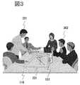
しかし、上記特許文献1に記載の投射型表示装置のように、机上等のように略水平な平面に対して投射して使用することが可能となり、その場合の課題を、図3を用いて説明する。図3は机上に投射して使用する使用形態(会議など)を示す図である。 However, like the projection display device described in Patent Document 1, it can be used by being projected onto a substantially horizontal plane such as on a desk, and the problem in that case is described with reference to FIG. explain. FIG. 3 is a diagram showing a usage pattern (conference etc.) used by projecting on a desk.
図3中、116は投射面(机上)、101は投射型表示装置、201は机に表示した投射画像、301、302は視聴者である。机上投射の用途では、図に示すように視聴者が投射画像201を取り囲む状態が多くなっている。この場合、視聴者の位置によって、投射画像201を見る方向が変わってくる。たとえば、投射画像201の上を図中右側とした場合、視聴者301に対して投射画像201の上下方向は一致している(視聴者301から見た上下方向と投射画像201の上下方向のずれが0度)が、視聴者302にとっては、投射画像201を上下逆(視聴者302から見た上下方向と投射画像201の上下方向のずれが180度)に見ることになり、視認性が悪くなる。 In FIG. 3, 116 is a projection surface (on the desk), 101 is a projection display device, 201 is a projection image displayed on a desk, and 301 and 302 are viewers. In the application of the desktop projection, as shown in the figure, the viewer surrounds the projected
上記特許文献1に記載の投射型表示装置においては、この点について何ら考慮されていない。 In the projection display device described in Patent Document 1, no consideration is given to this point.
本発明の目的は、会議などで、机上投射した投射画像を視聴者が取り囲んで見る場合においても、どの視聴者からも視認性がよい画像を投射する投射型表示装置を提供することである。 An object of the present invention is to provide a projection display device that projects an image with good visibility from any viewer even when a viewer surrounds and views a projected image projected on a desk at a meeting or the like.
本発明の投射型表示装置は、入力画像を第1の角度だけ回転処理させる第1画像回転処理部と、入力画像を第1の角度とは異なる第2の角度だけ回転処理させる第2画像回転処理部と、第1画像回転処理部と第2画像回転処理部で処理された画像を1画面に合成する2画面合成部を備える。 The projection display device of the present invention includes a first image rotation processing unit that rotates an input image by a first angle, and a second image rotation that rotates an input image by a second angle different from the first angle. A processing unit and a two-screen synthesis unit that synthesizes images processed by the first image rotation processing unit and the second image rotation processing unit into one screen are provided.
本発明のよれば、会議などで、机上投射した投射画像を視聴者が取り囲んで見る場合においても、どの視聴者からも視認性がよい画像を投射する投射型表示装置を実現できる。 According to the present invention, it is possible to realize a projection display device that projects an image with good visibility from any viewer, even when a viewer surrounds and views a projected image projected on a desk in a meeting or the like.
以下、本発明の最良の形態について図面を用いて説明する。なお、以下に述べる各図において、共通な機能を有する要素には同一な符号を付して示し、一度説明したものについては、その説明を省略する。 Hereinafter, the best mode of the present invention will be described with reference to the drawings. In each drawing described below, elements having common functions are denoted by the same reference numerals, and description of elements once described is omitted.
図1は第1の実施例を示す投射型表示装置のブロック図である。図1において、101は投射型表示装置、102は投射型表示装置全体の演算制御を行うCentral Processing Unit (以下「CPU」と省略する)、103はCPU102を制御するプログラムを格納するROM(Flash ROMを含む)、104はCPUがプログラムを実行する際に使用する演算結果等を格納するRAM、105は諸情報等を記憶する不揮発性メモリ、110は外部から映像信号(図示せず)が入力される入力端子、111は入力端子110から入力された映像信号に対して所定の信号処理を行う入力信号処理部である。 FIG. 1 is a block diagram of a projection display apparatus showing a first embodiment. In FIG. 1, 101 is a projection display device, 102 is a Central Processing Unit (hereinafter abbreviated as “CPU”) that performs arithmetic control of the entire projection display device, and 103 is a ROM (Flash ROM) that stores a program for controlling the
入力信号処理部111においては、アナログ-デジタル変換され、デジタルデータとして第1画像回転処理部106ならびに第2画像回転処理部107に入力される。第1画像回転処理部106は入力された画像に対して第1の角度だけ回転させる回転処理を行う(第1画像回転処理部で回転処理された表示画像を第1回転表示画像と称す)。第2画像回転処理部107は入力された画像に対して第1の角度とは異なる第2の角度だけ回転させる回転処理を行う(第2画像回転処理部で回転処理された表示画像を第2回転表示画像と称す)。 The input signal processing unit 111 performs analog-to-digital conversion and inputs the digital data to the first image
108は2画面合成部であり、第1画像回転処理部106、第2画像回転処理部107から出力される画像回転処理後の第1回転表示画像と第2回転表示画像を1画面に合成する。109は2画面合成部108から出力された映像信号に対して、映像の拡大、縮小ならびに幾何学歪補正などのスケーリングを行う画像処理部である。
尚、本実施例では映像の拡大、縮小を2画面合成後に画像処理部109で実施しているが、予め第1画像回転処理部106と第2画像回転処理部107で実施しても良いし、2画面合成部108にて第1画像回転処理部106、第2画像回転処理部107から出力される画像回転処理後の第1回転表示画像と第2回転表示画像を個別に実施してもよい。また、第1画像回転処理部106、第2画像回転処理部107、2画面合成部108、画像処理部109で組み合わせて実施しても良い。 In this embodiment, image enlargement / reduction is performed by the
112は駆動回路、113は照明光学ブロック、114は液晶パネル、115は投射レンズブロック、116は投射面である。照明光学ブロック113は、光源(図示せず)からの光を偏向変換素子(図示せず)によりランダム偏光を直線偏光に変換し、液晶パネル114に照射する。液晶パネル114は照明光学ブロック113より照射された光の透過量を制御するものであり、画像処理部109から出力された画像データを基に、駆動回路112が液晶パネル114の画素ごとの透過率を制御することで画像を形成している。ここでは、液晶パネル114は高解像度の横長のLCDパネルで構成されている。投射レンズブロック115は液晶パネルを透過した光(映像)を拡大して投射するものであり、液晶パネル114上に形成された画像が投射面116に映し出される。117は操作部であり、投射型表示装置101の筐体上に配設された複数のボタンからなる操作ボタンや、リモートコントローラー(以下、「リモコン」と省略する)からの赤外線(Infrared)リモートコントロール信号(以下、「IRリモート信号」と省略する)により制御するものである。 Reference numeral 112 denotes a driving circuit, 113 denotes an illumination optical block, 114 denotes a liquid crystal panel, 115 denotes a projection lens block, and 116 denotes a projection surface. The illumination
図2は、投射画像を示す図である。201は表示画像、202は第1回転表示画像、203は第2回転表示画像である。図2(a)は、机上等の略水平面に投射する場合に2画面回転表示を行ったときの表示例であり、図2(b)は、通常のスクリーン等の略垂直面に1画面表示を行ったときの表示例である。 FIG. 2 is a diagram illustrating a projected image. 201 is a display image, 202 is a first rotation display image, and 203 is a second rotation display image. FIG. 2A is a display example when a two-screen rotation display is performed when projecting on a substantially horizontal surface such as a desktop, and FIG. 2B is a one-screen display on a substantially vertical surface such as a normal screen. It is an example of a display when performing.
最初に、机上等の略水平面に投射する場合に使用する2画面回転表示を行うときの動作について述べる。 First, an operation when performing a two-screen rotation display used when projecting on a substantially horizontal plane such as a desk will be described.
入力端子110から入力された映像信号は、入力信号処理部111においてアナログ-デジタル変換され、デジタルデータとして第1画像回転処理部106ならびに第2画像回転処理部107に入力される。第1画像回転処理部106に入力された画像は第1の角度(時計回りに90度)だけ回転処理し第1回転表示画像204となる。 The video signal input from the
一方第2画像回転処理部107に入力された画像は第2の角度(時計回りに270度)だけ回転処理し第2回転表示画像203となる。それぞれ回転処理された画像信号は2画面合成部108へ入力され1画面に合成される。本実施例において、2画面合成部108での1画面への合成は、各回転表示画像202,203が左右2画面に配置されるように合成される。 On the other hand, the image input to the second image
次に、前記2画面合成部108にて合成された画像信号は画像処理部109に入力され、画像処理部109で、映像の拡大、縮小ならびに幾何学歪補正などのスケーリングが行われ、駆動回路112に出力される。駆動回路112は、本入力信号に従い液晶パネル114を制御し、図2(a)に示すような投射画像が表示される。 Next, the image signal synthesized by the two-
一般的に、入力画像は横長の画像である。液晶パネル114も横長であることから、上記のように第1の角度を時計回りに90度、第2の角度を時計回りに270度とした場合が、入力画像を最も大きく表示することが可能となる。また、第1回転処理画像202の上側と第2回転処理画像203の上側が接するように合成されるため、図3のように投射画像201を多数の視聴者が取り囲んで全方向から見る場合においても、視聴者は第1回転処理画像202あるいは第2回転処理画像203の自分に近い方を見ることで、視聴者から見た上下方向と回転処理画像(202あるいは203)の上下方向のずれは90度以下となる。 In general, the input image is a horizontally long image. Since the
従来の1画面表示では、視聴者から見た上下方向と、投射画像の上下方向のずれが90度以上となる視認性の悪い視聴者が多数出てきたが、図2(a)のような2画面回転表示とすることにより、その問題はなくなる。 In the conventional single-screen display, many viewers with poor visibility that the vertical shift of the projected image and the vertical shift of the projected image are 90 degrees or more have come out, as shown in FIG. The problem is eliminated by the two-screen rotation display.
次に、スクリーン等の略垂直面に投射する場合の、1画面表示について説明する。入力端子110から入力された映像信号は、入力信号処理部111においてアナログ-デジタル変換され、デジタルデータとして第1画像回転処理部106に入力される。このとき、CPU102は、第1画像回転処理部106に対して、回転処理をせず入力信号をそのまま出力するよう制御する。2画面合成部108に対しては、第1回転処理部106からの1画面のみの画像を出力するように制御する。第2回転処理部107に入力された画像信号は使用されない。2画面合成部108から出力された画像信号は、画像処理部109において、1画面表示時の映像の拡大または縮小比率を設定するとともに幾何学歪補正などのスケーリングが行われ、駆動回路112に出力される。駆動回路112は、本入力信号に従い液晶パネル114を制御する。したがって、表示される画像は図2(b)に示すような画像となる。 Next, one-screen display when projecting on a substantially vertical surface such as a screen will be described. The video signal input from the
図2(a)の2画面回転表示を行うか、図2(b)の1画面表示を行うかは、使用者(ユーザー)が選択できるようになっている。これは、使用者が操作ボタンによる入力により、操作部117からCPU102に表示を切り替える制御信号を送るようになっている。あるいは使用者がリモコンによる入力することで、リモコンからIRリモート信号が送信され、操作部117からCPU102に表示を切り替える制御信号を送るようになっている。また、投射型表示装置101内部に角度センサなど配置し、投射型表示装置101が机上などの略水平面に対して映像を投射していると判別した場合は、自動的に図2(a)のような2画面回転表示に切り替えるようにしてもよい。 The user (user) can select whether to perform the two-screen rotation display in FIG. 2A or the one-screen display in FIG. In this case, the control signal for switching the display is sent from the
前記角度センサは、前記投射型表示装置101の設置されている設置の角度、若しくは、前記投射型表示装置101の姿勢の角度を検出することで、略水平面に対して映像を投射しているのか、略垂直面に対して映像を投射しているのかを検出、判断できるようにしても良い。 Does the angle sensor project an image on a substantially horizontal plane by detecting the installation angle of the
または、前記レンズから出射される光束の投射方向の角度を検出するようにするか、前記レンズの角度を検出するようにして、略水平面に対して映像を投射しているのか、略垂直面に対して映像を投射しているのかを検出、判断できるようにしても良い。 Alternatively, the angle of the projection direction of the light beam emitted from the lens is detected, or the angle of the lens is detected to project an image on a substantially horizontal plane, or on a substantially vertical plane. On the other hand, it may be possible to detect and determine whether an image is projected.
よって、上記したように、投射画像内の各画面を個別に回転させて表示することにより、どの視聴者からも視認性がよい画像を投射する投射型表示装置を実現できる。 Therefore, as described above, by projecting and rotating each screen in the projection image individually, it is possible to realize a projection display device that projects an image with high visibility from any viewer.
101:投射型表示装置
102:CPU
103:ROM
104:RAM
105:不揮発性メモリ
106:第1画像回転処理部
107:第2画像回転処理部
108:2画面合成部、
109:画像処理部
110:入力端子
111:入力信号処理部
112:駆動回路、
113:照明光学ブロック
114:液晶パネル
115:投射レンズブロック
116:投射面
117:操作部
201:表示画像
202:第1回転表示画像
203:第2回転表示画像101: Projection display device 102: CPU
103: ROM
104: RAM
105: Non-volatile memory 106: First image rotation processing unit 107: Second image rotation processing unit 108: Two-screen composition unit
109: image processing unit 110: input terminal 111: input signal processing unit 112: drive circuit,
113: Illumination optical block 114: Liquid crystal panel 115: Projection lens block 116: Projection surface 117: Operation unit 201: Display image 202: First rotation display image 203: Second rotation display image
Claims (11)
Translated fromJapanese光束を照射する照明光学ブロックと、
当該照明光学ブロックからの照射光を前記画像処理部からの出力信号に応じて変調して出射する液晶パネルと、
当該液晶パネルからの出射光を被投射体に投射する投射レンズブロックと
を有する投射型表示装置において、
前記画像処理部は、
入力画像を第1の角度だけ回転処理させる第1画像回転処理部と、
入力画像を第2の角度だけ回転処理させる第2画像回転処理部と、
第1画像回転処理部からの第1の出力画像と第2画像回転処理部からの第2の出力画像とを1画面に合成する2画面合成部と
を備える
ことを特徴とする投射型表示装置。An image processing unit that processes the input image;
An illumination optical block for irradiating a light beam;
A liquid crystal panel that modulates and emits irradiation light from the illumination optical block according to an output signal from the image processing unit;
In a projection display device having a projection lens block that projects light emitted from the liquid crystal panel onto a projection target,
The image processing unit
A first image rotation processing unit that rotates the input image by a first angle;
A second image rotation processing unit that rotates the input image by a second angle;
A projection-type display device comprising: a two-screen composition unit for synthesizing the first output image from the first image rotation processing unit and the second output image from the second image rotation processing unit into one screen. .
前記画像処理部は、
前記2画面合成部から出力される出力画像の拡大、縮小ならびに幾何学歪補正を含むスケーリング処理を行う
ことを特徴とする投射型表示装置。The projection display device according to claim 1,
The image processing unit
A projection-type display device that performs scaling processing including enlargement and reduction of an output image output from the two-screen composition unit and correction of geometric distortion.
前記第1画像回転処理部、または前記第2画像回転処理部が、
入力画像の拡大、縮小のスケーリング処理を行う
ことを特徴とする投射型表示装置。The projection display device according to claim 1,
The first image rotation processing unit or the second image rotation processing unit;
A projection display device that performs scaling processing for enlarging or reducing an input image.
前記第1画像処理部、または前記第2画像回転処理部が、
前記2画面合成部から出力される出力画像の拡大、縮小ならびに幾何学歪補正を含むスケーリング処理を行う
ことを特徴とする投射型表示装置。In the projection type display device according to claim 3,
The first image processing unit or the second image rotation processing unit;
A projection-type display device that performs scaling processing including enlargement and reduction of an output image output from the two-screen composition unit and correction of geometric distortion.
前記2画面合成部は、
第1画像回転処理部からの第1の出力画像と第2画像回転処理部からの第2の出力画像を個別に拡大、縮小のスケーリング処理を行った後、画面合成を行うことを特徴とする投射型表示装置。The projection display device according to claim 1,
The two-screen composition unit
The first output image from the first image rotation processing unit and the second output image from the second image rotation processing unit are individually subjected to scaling processing for enlargement and reduction, and then screen synthesis is performed. Projection display device.
前記画像処理部は、
前記2画面合成部から出力される出力画像の拡大、縮小ならびに幾何学歪補正を含むスケーリング処理を行う
ことを特徴とする投射型表示装置。In the projection type display device according to claim 5,
The image processing unit
A projection-type display device that performs scaling processing including enlargement and reduction of an output image output from the two-screen composition unit and correction of geometric distortion.
上記第1の角度と第2の角度は180度異なっている
ことを特徴とする投射型表示装置。The projection display device according to any one of claims 1 to 6,
The projection display device, wherein the first angle and the second angle are different from each other by 180 degrees.
上記第1の角度が90度(時計回り)であることを特徴とする投射型表示装置。The projection display device according to any one of claims 1 to 6,
A projection type display apparatus, wherein the first angle is 90 degrees (clockwise).
前記投射レンズブロックからの出射光が略垂直面の被投射体に投射される場合には、
前記画像処理部からは1画面の出力画像が出力されることを特徴とする投射型表示装置。The projection display device according to any one of claims 1 to 6,
When the light emitted from the projection lens block is projected onto a substantially vertical projection object,
A projection-type display device, wherein an output image of one screen is output from the image processing unit.
前記投射型表示装置は、ユーザの操作を受付ける操作部を有しており、
当該操作部からの信号を受けて、前記画像処理部からの出力画像を1画面の出力画像、または2画面の出力画像に切替える
ことを特徴とする投射型表示装置。In the projection display device according to claim 9,
The projection display device has an operation unit that receives a user operation,
A projection display device that receives a signal from the operation unit and switches an output image from the image processing unit to a one-screen output image or a two-screen output image.
前記投射型表示装置は、
前記投射型表示装置の設置された角度、若しくは、前記投射型表示装置の設置された角度、
または、前記投射レンズブロックの角度、若しくは、前記投射レンズブロックから出射される出射光の角度
を検出する角度センサを設け、
当該角度センサからの信号を受けて、前記画像処理部からの出力画像を1画面の出力画像、または2画面の出力画像に切替える
ことを特徴とする投射型表示装置。In the projection type display device according to claim 9,
The projection display device
The installation angle of the projection display device, or the installation angle of the projection display device,
Alternatively, an angle sensor that detects an angle of the projection lens block or an angle of outgoing light emitted from the projection lens block is provided,
A projection type display device that receives a signal from the angle sensor and switches an output image from the image processing unit to an output image of one screen or an output image of two screens.
Priority Applications (4)
| Application Number | Priority Date | Filing Date | Title |
|---|---|---|---|
| JP2009083961AJP2010237347A (en) | 2009-03-31 | 2009-03-31 | Projection display |
| CN2009102540516ACN101852973B (en) | 2009-03-31 | 2009-12-15 | projection display device |
| CN201210169423.7ACN102662296B (en) | 2009-03-31 | 2009-12-15 | Projection type image display apparatus |
| US12/645,824US8314894B2 (en) | 2009-03-31 | 2009-12-23 | Projection type table display |
Applications Claiming Priority (1)
| Application Number | Priority Date | Filing Date | Title |
|---|---|---|---|
| JP2009083961AJP2010237347A (en) | 2009-03-31 | 2009-03-31 | Projection display |
Related Child Applications (1)
| Application Number | Title | Priority Date | Filing Date |
|---|---|---|---|
| JP2013194815ADivisionJP2014041360A (en) | 2013-09-20 | 2013-09-20 | Projection type display device |
Publications (1)
| Publication Number | Publication Date |
|---|---|
| JP2010237347Atrue JP2010237347A (en) | 2010-10-21 |
Family
ID=42783744
Family Applications (1)
| Application Number | Title | Priority Date | Filing Date |
|---|---|---|---|
| JP2009083961APendingJP2010237347A (en) | 2009-03-31 | 2009-03-31 | Projection display |
Country Status (3)
| Country | Link |
|---|---|
| US (1) | US8314894B2 (en) |
| JP (1) | JP2010237347A (en) |
| CN (2) | CN102662296B (en) |
Cited By (2)
| Publication number | Priority date | Publication date | Assignee | Title |
|---|---|---|---|---|
| JP2014115362A (en)* | 2012-12-07 | 2014-06-26 | Seiko Epson Corp | Projector and display control method for projector |
| WO2015075767A1 (en)* | 2013-11-19 | 2015-05-28 | 日立マクセル株式会社 | Projection-type video display device |
Families Citing this family (13)
| Publication number | Priority date | Publication date | Assignee | Title |
|---|---|---|---|---|
| US9925464B2 (en) | 2011-03-08 | 2018-03-27 | Nintendo Co., Ltd. | Computer-readable storage medium, information processing system, and information processing method for displaying an image on a display device using attitude data of a display device |
| JP5792971B2 (en) | 2011-03-08 | 2015-10-14 | 任天堂株式会社 | Information processing system, information processing program, and information processing method |
| EP2497547B1 (en)* | 2011-03-08 | 2018-06-27 | Nintendo Co., Ltd. | Information processing program, information processing apparatus, information processing system, and information processing method |
| EP2497545B1 (en) | 2011-03-08 | 2019-08-07 | Nintendo Co., Ltd. | Information processing program, information processing system, and information processing method |
| EP2497544A3 (en) | 2011-03-08 | 2012-10-03 | Nintendo Co., Ltd. | Information processing program, information processing system, and information processing method |
| EP2497543A3 (en) | 2011-03-08 | 2012-10-03 | Nintendo Co., Ltd. | Information processing program, information processing system, and information processing method |
| CN102761760A (en)* | 2011-12-01 | 2012-10-31 | 联想(北京)有限公司 | Display method, display device and electric terminal |
| JP6200328B2 (en) | 2011-12-21 | 2017-09-20 | パナソニック インテレクチュアル プロパティ コーポレーション オブ アメリカPanasonic Intellectual Property Corporation of America | Display device |
| CN104077102A (en)* | 2014-07-01 | 2014-10-01 | 四川政企网络信息服务有限公司 | Image display device and method supporting interactive display with intelligent terminal |
| JP6628036B2 (en)* | 2015-03-27 | 2020-01-08 | パナソニックIpマネジメント株式会社 | Video display control device, video display system, and video display control method |
| CN105791785A (en)* | 2016-02-04 | 2016-07-20 | 深圳前海勇艺达机器人有限公司 | Projection device |
| CN110300239A (en)* | 2018-03-22 | 2019-10-01 | 精工爱普生株式会社 | Image processing apparatus, image processing method and display device |
| JP2023007083A (en) | 2021-07-01 | 2023-01-18 | セイコーエプソン株式会社 | image display system |
Citations (4)
| Publication number | Priority date | Publication date | Assignee | Title |
|---|---|---|---|---|
| JPH05197444A (en)* | 1992-01-17 | 1993-08-06 | Hitachi Ltd | Portable information equipment |
| JP2005012407A (en)* | 2003-06-18 | 2005-01-13 | Sony Corp | Picture projection device and picture processing method |
| JP2006235523A (en)* | 2005-02-28 | 2006-09-07 | Brother Ind Ltd | Display device |
| JP2009237337A (en)* | 2008-03-27 | 2009-10-15 | Sanyo Electric Co Ltd | Projection type image display device and projection type image display system using same |
Family Cites Families (8)
| Publication number | Priority date | Publication date | Assignee | Title |
|---|---|---|---|---|
| US5386378A (en)* | 1990-06-05 | 1995-01-31 | Matsushita Electric Industrial Co., Ltd. | Optical information processing apparatus and method using computer generated hologram |
| US6677936B2 (en)* | 1996-10-31 | 2004-01-13 | Kopin Corporation | Color display system for a camera |
| US6486862B1 (en)* | 1996-10-31 | 2002-11-26 | Kopin Corporation | Card reader display system |
| JP2001086367A (en)* | 1999-09-10 | 2001-03-30 | Matsushita Electric Ind Co Ltd | Image display device and control method thereof |
| US7714943B2 (en)* | 2002-06-12 | 2010-05-11 | Geo Semiconductor Inc. | Ultra-thin image projection system |
| JP4538598B2 (en)* | 2003-01-08 | 2010-09-08 | ジーイーオー セミコンダクター インコーポレイテッド | Off-axis projection system and method |
| WO2006098402A1 (en)* | 2005-03-17 | 2006-09-21 | Brother Kogyo Kabushiki Kaisha | Projector |
| JP5125147B2 (en) | 2007-02-27 | 2013-01-23 | 株式会社日立製作所 | Projection display |
- 2009
- 2009-03-31JPJP2009083961Apatent/JP2010237347A/enactivePending
- 2009-12-15CNCN201210169423.7Apatent/CN102662296B/enactiveActive
- 2009-12-15CNCN2009102540516Apatent/CN101852973B/enactiveActive
- 2009-12-23USUS12/645,824patent/US8314894B2/enactiveActive
Patent Citations (4)
| Publication number | Priority date | Publication date | Assignee | Title |
|---|---|---|---|---|
| JPH05197444A (en)* | 1992-01-17 | 1993-08-06 | Hitachi Ltd | Portable information equipment |
| JP2005012407A (en)* | 2003-06-18 | 2005-01-13 | Sony Corp | Picture projection device and picture processing method |
| JP2006235523A (en)* | 2005-02-28 | 2006-09-07 | Brother Ind Ltd | Display device |
| JP2009237337A (en)* | 2008-03-27 | 2009-10-15 | Sanyo Electric Co Ltd | Projection type image display device and projection type image display system using same |
Cited By (5)
| Publication number | Priority date | Publication date | Assignee | Title |
|---|---|---|---|---|
| JP2014115362A (en)* | 2012-12-07 | 2014-06-26 | Seiko Epson Corp | Projector and display control method for projector |
| WO2015075767A1 (en)* | 2013-11-19 | 2015-05-28 | 日立マクセル株式会社 | Projection-type video display device |
| JP5973087B2 (en)* | 2013-11-19 | 2016-08-23 | 日立マクセル株式会社 | Projection-type image display device |
| US9927923B2 (en) | 2013-11-19 | 2018-03-27 | Hitachi Maxell, Ltd. | Projection-type video display device |
| US10191594B2 (en) | 2013-11-19 | 2019-01-29 | Maxell, Ltd. | Projection-type video display device |
Also Published As
| Publication number | Publication date |
|---|---|
| CN101852973B (en) | 2012-11-28 |
| US8314894B2 (en) | 2012-11-20 |
| CN102662296A (en) | 2012-09-12 |
| US20100245685A1 (en) | 2010-09-30 |
| CN102662296B (en) | 2015-07-29 |
| CN101852973A (en) | 2010-10-06 |
Similar Documents
| Publication | Publication Date | Title |
|---|---|---|
| JP2010237347A (en) | Projection display | |
| CN102455575B (en) | Projection display device and control method thereof | |
| JP6429545B2 (en) | Control device and control method | |
| US9632401B2 (en) | Projector | |
| JP2016014713A (en) | Image projection apparatus, image projection method, and control program for image projection apparatus | |
| JP6263881B2 (en) | Image projection apparatus, control method for image projection apparatus, and control program for image projection apparatus | |
| JP2008233462A (en) | Projector and projection method of projector | |
| JP6915060B2 (en) | Projection type video display device | |
| JP2006313979A (en) | Projector and projector control method | |
| JP2007329530A (en) | Video equipment, video equipment display processing method, and video equipment processing program | |
| JP2014041360A (en) | Projection type display device | |
| JP2004029110A (en) | Projection display device | |
| JPH08163476A (en) | Liquid crystal projector with stand | |
| US11706393B2 (en) | Projection-type display device and method for adjusting a projected image | |
| JP2006054824A (en) | Projection image display device | |
| JP2007225859A (en) | projector | |
| JP2008112035A (en) | projector | |
| JP2008079016A (en) | projector | |
| JP6415176B2 (en) | Projection display | |
| US20200145628A1 (en) | Projection apparatus and correcting method of display image | |
| JP7427804B2 (en) | Control device, control method, control program, and projection system | |
| TWI250374B (en) | Method for electronic adjustment of the geometry in a videoprojector used in back projection and a videoprojector utilizing the method thereof | |
| JP7693894B2 (en) | Projection device and control method thereof | |
| JP2008233465A (en) | Projector and projection method of projector | |
| JP2020154191A (en) | Image projection device and its control method |
Legal Events
| Date | Code | Title | Description |
|---|---|---|---|
| A621 | Written request for application examination | Free format text:JAPANESE INTERMEDIATE CODE: A621 Effective date:20110928 | |
| A977 | Report on retrieval | Free format text:JAPANESE INTERMEDIATE CODE: A971007 Effective date:20130117 | |
| A131 | Notification of reasons for refusal | Free format text:JAPANESE INTERMEDIATE CODE: A131 Effective date:20130122 | |
| A521 | Request for written amendment filed | Free format text:JAPANESE INTERMEDIATE CODE: A523 Effective date:20130325 | |
| A711 | Notification of change in applicant | Free format text:JAPANESE INTERMEDIATE CODE: A712 Effective date:20130529 | |
| A02 | Decision of refusal | Free format text:JAPANESE INTERMEDIATE CODE: A02 Effective date:20130625 | |
| A521 | Request for written amendment filed | Free format text:JAPANESE INTERMEDIATE CODE: A523 Effective date:20130920 | |
| A521 | Request for written amendment filed | Free format text:JAPANESE INTERMEDIATE CODE: A523 Effective date:20130920 | |
| A911 | Transfer to examiner for re-examination before appeal (zenchi) | Free format text:JAPANESE INTERMEDIATE CODE: A911 Effective date:20131011 | |
| A912 | Re-examination (zenchi) completed and case transferred to appeal board | Free format text:JAPANESE INTERMEDIATE CODE: A912 Effective date:20131206 | |
| RD02 | Notification of acceptance of power of attorney | Free format text:JAPANESE INTERMEDIATE CODE: A7422 Effective date:20140310 | |
| RD04 | Notification of resignation of power of attorney | Free format text:JAPANESE INTERMEDIATE CODE: A7424 Effective date:20140319 | |
| A711 | Notification of change in applicant | Free format text:JAPANESE INTERMEDIATE CODE: A712 Effective date:20140917 | |
| A521 | Request for written amendment filed | Free format text:JAPANESE INTERMEDIATE CODE: A821 Effective date:20140917 | |
| A521 | Request for written amendment filed | Free format text:JAPANESE INTERMEDIATE CODE: A523 Effective date:20141201 |