JP2010237311A - Projection video display device - Google Patents
Projection video display deviceDownload PDFInfo
- Publication number
- JP2010237311A JP2010237311AJP2009083208AJP2009083208AJP2010237311AJP 2010237311 AJP2010237311 AJP 2010237311AJP 2009083208 AJP2009083208 AJP 2009083208AJP 2009083208 AJP2009083208 AJP 2009083208AJP 2010237311 AJP2010237311 AJP 2010237311A
- Authority
- JP
- Japan
- Prior art keywords
- light
- projection
- light source
- unit
- solid
- Prior art date
- Legal status (The legal status is an assumption and is not a legal conclusion. Google has not performed a legal analysis and makes no representation as to the accuracy of the status listed.)
- Pending
Links
- 239000007787solidSubstances0.000claimsabstractdescription128
- 239000013307optical fiberSubstances0.000claimsabstractdescription97
- 230000001788irregularEffects0.000abstract1
- 238000001816coolingMethods0.000description32
- 230000004048modificationEffects0.000description18
- 238000012986modificationMethods0.000description18
- 238000000926separation methodMethods0.000description15
- 238000000034methodMethods0.000description9
- 230000015572biosynthetic processEffects0.000description8
- 238000003786synthesis reactionMethods0.000description8
- 238000010586diagramMethods0.000description7
- 238000005452bendingMethods0.000description4
- 230000005540biological transmissionEffects0.000description3
- 230000000694effectsEffects0.000description2
- 238000003384imaging methodMethods0.000description2
- 239000004973liquid crystal related substanceSubstances0.000description2
- 239000011521glassSubstances0.000description1
- 238000004519manufacturing processMethods0.000description1
- 239000000203mixtureSubstances0.000description1
- 238000013022ventingMethods0.000description1
Images


Landscapes
- Transforming Electric Information Into Light Information (AREA)
- Projection Apparatus (AREA)
Abstract
Description
Translated fromJapanese本発明は、複数の固体光源によって構成される光源ユニットと、複数の固体光源から出射される光を変調する光変調素子と、光変調素子から出射される光を投写面上に投写する投写ユニットとを備える投写型映像表示装置に関する。 The present invention relates to a light source unit composed of a plurality of solid light sources, a light modulation element that modulates light emitted from the plurality of solid light sources, and a projection unit that projects light emitted from the light modulation elements onto a projection surface. And a projection display apparatus comprising:
近年、レーザ光源などの固体光源と、固体光源から出射された光を変調する光変調素子と、光変調素子から出射された光を投写面上に投写する投写ユニットとを有する投写型映像表示装置が知られている。 2. Description of the Related Art In recent years, a projection display apparatus having a solid light source such as a laser light source, a light modulation element that modulates light emitted from the solid light source, and a projection unit that projects light emitted from the light modulation element onto a projection surface. It has been known.
ここで、投写面上に映像を大きく表示するためには、投写ユニットと投写面との距離を長くとる必要がある。これに対して、投写ユニットから出射される光を投写面側に反射する反射ミラーを利用して、投写ユニットと投写面との距離の短縮を図った投写型表示システムが提案されている(例えば、特許文献1)。 Here, in order to display a large image on the projection surface, it is necessary to increase the distance between the projection unit and the projection surface. On the other hand, a projection display system has been proposed in which a distance between the projection unit and the projection surface is reduced by using a reflection mirror that reflects light emitted from the projection unit to the projection surface side (for example, Patent Document 1).
また、必要光量を確保するために、複数の固体光源によって構成される光源ユニットを有する投写型映像表示装置が提案されている(例えば、特許文献2)。 In order to secure the necessary light quantity, a projection display apparatus having a light source unit composed of a plurality of solid state light sources has been proposed (for example, Patent Document 2).
複数の固体光源のそれぞれは、複数の光ファイバーのそれぞれに接続されており、複数の光ファイバーは、バンドル部で束ねられる。各固体光源から出射された光は、各光ファイバーによってバンドル部に集められ、バンドル部で束ねられた各光ファイバーから出射される光が光変調素子に導かれる。 Each of the plurality of solid state light sources is connected to each of the plurality of optical fibers, and the plurality of optical fibers are bundled by a bundle unit. The light emitted from each solid light source is collected in a bundle part by each optical fiber, and the light emitted from each optical fiber bundled in the bundle part is guided to the light modulation element.
ところで、投写面において生じる光量ムラは、各固体光源が各光ファイバーを介してバンドル部に接続される位置の入れ替えによって抑制することができる。 By the way, the unevenness in the amount of light that occurs on the projection surface can be suppressed by switching the positions at which the solid-state light sources are connected to the bundle portion via the optical fibers.
各固体光源が各光ファイバーを介してバンドル部に接続される位置の入れ替え方法としては、以下に示す方法が考えられる。 As a method for changing the position where each solid-state light source is connected to the bundle portion via each optical fiber, the following method can be considered.
(1)固体光源と光ファイバーとの組み合わせを変更せずに、各光ファイバーがバンドル部に接続される位置の入れ替える方法
(2)光源ユニットにおける各固体光源の配置位置の入れ替えによって、固体光源と光ファイバーとの組み合わせを変更する方法
(3)光源ユニットにおける各固体光源の配置位置を変更せずに、固体光源から光ファイバーを取り外した上で、固体光源に接続すべき光ファイバーを入れ替えることによって、固体光源と光ファイバーとの組み合わせを変更する方法
ここで、各光ファイバーはバンドル部で束ねられており、光ファイバーが束ねられた状態で光ファイバーがバンドル部に接続される位置を入れ替えることは難しく、(1)の方法は困難である。また、固体光源は光源ユニットにネジ止め等によって固定されるため、(2)の方法も困難である。すなわち、上述した方法のうち、(3)の方法が最も容易である。(1) A method of changing the position where each optical fiber is connected to the bundle part without changing the combination of the solid light source and the optical fiber. (2) By changing the arrangement position of each solid light source in the light source unit, (3) Without changing the arrangement position of each solid light source in the light source unit, after removing the optical fiber from the solid light source and replacing the optical fiber to be connected to the solid light source, the solid light source and the optical fiber Here, each optical fiber is bundled in the bundle part, and it is difficult to change the position where the optical fiber is connected to the bundle part in the state where the optical fiber is bundled, and the method (1) is difficult. It is. Further, since the solid light source is fixed to the light source unit by screws or the like, the method (2) is also difficult. That is, among the methods described above, the method (3) is the easiest.
ここで、光ファイバーの長さに余裕を持たせると、光ファイバーを曲げなければならないため、固体光源から出射される光の利用効率が低下する。従って、バンドル部から固体光源までの距離に合わせて光ファイバーの長さを定めることが好ましい。 Here, if there is a margin in the length of the optical fiber, the optical fiber must be bent, so that the utilization efficiency of the light emitted from the solid light source is lowered. Therefore, it is preferable to determine the length of the optical fiber in accordance with the distance from the bundle portion to the solid light source.
一方で、バンドル部から固体光源までの距離は、固体光源毎に異なっている。従って、固体光源に接続すべき光ファイバーの入れ替えようとしても、光ファイバーの長さが不足するケース、光ファイバーの長さが超過するケースが考えられる。 On the other hand, the distance from the bundle portion to the solid light source is different for each solid light source. Therefore, there are cases where the length of the optical fiber is short or the length of the optical fiber is long, even if the optical fiber to be connected to the solid light source is replaced.
このように、光ファイバーの長さの不足や光ファイバーの長さの超過は、色ムラの原因となる可能性がある。 Thus, an insufficient length of the optical fiber or an excessive length of the optical fiber may cause color unevenness.
そこで、本発明は、上述した課題を解決するためになされたものであり、色ムラの発生を抑制することを可能とする投写型映像表示装置を提供することを目的とする。 Accordingly, the present invention has been made to solve the above-described problems, and an object thereof is to provide a projection display apparatus that can suppress the occurrence of color unevenness.
第1の特徴に係る投写型映像表示装置は、複数の固体光源(赤固体光源111R、緑固体光源111G、青固体光源111B)によって構成される光源ユニット(光源ユニット110)と、前記複数の固体光源から出射される光を変調する光変調素子(DMD500R、DMD500G、DMD500B)と、前記光変調素子から出射される光を投写面上に投写する投写ユニット(投写ユニット150)とを備える。前記複数の固体光源のそれぞれは、複数の光ファイバー(光ファイバー113)のそれぞれに接続されている。前記複数の光ファイバーは、バンドル部(バンドル部114)で束ねられている。前記バンドル部で束ねられる前記複数の光ファイバーから出射される光は、前記光変調素子に導かれる。前記複数の光ファイバーのそれぞれの長さは同じである。 The projection display apparatus according to the first feature includes a light source unit (light source unit 110) including a plurality of solid light sources (red
第1の特徴において、前記複数の光ファイバーは、複数のグループに分類されており、前記複数のグループ毎に分類された光ファイバーの長さは、前記複数のグループ毎に同じである。 In the first feature, the plurality of optical fibers are classified into a plurality of groups, and the lengths of the optical fibers classified into the plurality of groups are the same for the plurality of groups.
第1の特徴において、前記複数の固体光源のそれぞれは、前記複数の固体光源のそれぞれと前記バンドル部との距離が同じとなる位置に設けられる。 In the first feature, each of the plurality of solid light sources is provided at a position where the distance between each of the plurality of solid light sources and the bundle portion is the same.
第1の特徴において、前記光源ユニットは、前記複数の固体光源のそれぞれと前記バンドル部との距離を変更するように、前記複数の固体光源のそれぞれをスライドするスライド機構を有する。 1st characteristic WHEREIN: The said light source unit has a slide mechanism which slides each of these solid light sources so that the distance of each of these solid light sources and the said bundle part may be changed.
本発明によれば、色ムラの発生を抑制することを可能とする投写型映像表示装置を提供することができる。 ADVANTAGE OF THE INVENTION According to this invention, the projection type video display apparatus which can suppress generation | occurrence | production of a color nonuniformity can be provided.
以下において、本発明の実施形態に係る投写型映像表示装置について、図面を参照しながら説明する。なお、以下の図面の記載において、同一又は類似の部分には、同一又は類似の符号を付している。 Hereinafter, a projection display apparatus according to an embodiment of the present invention will be described with reference to the drawings. In the following description of the drawings, the same or similar parts are denoted by the same or similar reference numerals.
ただし、図面は模式的なものであり、各寸法の比率などは現実のものとは異なることに留意すべきである。従って、具体的な寸法などは以下の説明を参酌して判断すべきである。また、図面相互間においても互いの寸法の関係や比率が異なる部分が含まれていることは勿論である。 However, it should be noted that the drawings are schematic and ratios of dimensions are different from actual ones. Therefore, specific dimensions and the like should be determined in consideration of the following description. Moreover, it is a matter of course that portions having different dimensional relationships and ratios are included between the drawings.
[実施形態の概要]
実施形態に係る投写型映像表示装置は、複数の固体光源によって構成される光源ユニットと、複数の固体光源から出射される光を変調する光変調素子と、光変調素子から出射される光を投写面上に投写する投写ユニットとを備える。複数の固体光源のそれぞれは、複数の光ファイバーのそれぞれに接続されている。複数の光ファイバーは、バンドル部で束ねられている。バンドル部で束ねられる複数の光ファイバーから出射される光は、光変調素子に導かれる。複数の光ファイバーのそれぞれの長さは同じである。[Outline of Embodiment]
A projection display apparatus according to an embodiment projects a light source unit including a plurality of solid light sources, a light modulation element that modulates light emitted from the plurality of solid light sources, and light emitted from the light modulation elements. And a projection unit that projects onto the surface. Each of the plurality of solid light sources is connected to each of the plurality of optical fibers. The plurality of optical fibers are bundled at a bundle portion. Light emitted from the plurality of optical fibers bundled in the bundle portion is guided to the light modulation element. Each of the plurality of optical fibers has the same length.
実施形態では、複数の光ファイバーのそれぞれの長さは同じである。従って、各固体光源の配置位置を変更せずに、固体光源に接続すべき光ファイバーの入れ替えによって、固体光源と光ファイバーとの組み合わせを変更しても、光ファイバーの長さの不足や光ファイバーの長さの超過が生じない。すなわち、光の利用効率の低下を抑制しながら、固体光源が各光ファイバーを介してバンドル部に接続される位置を容易に入れ替えることができる。 In the embodiment, each of the plurality of optical fibers has the same length. Therefore, even if the combination of the solid light source and the optical fiber is changed by replacing the optical fiber to be connected to the solid light source without changing the arrangement position of each solid light source, the shortage of the optical fiber or the length of the optical fiber There is no excess. That is, the position where the solid light source is connected to the bundle portion via each optical fiber can be easily replaced while suppressing a decrease in light utilization efficiency.
[第1実施形態]
(投写型映像表示装置の構成)
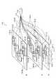
以下において、第1実施形態に係る投写型映像表示装置の構成について、図面を参照しながら説明する。図1は、第1実施形態に係る投写型映像表示装置100を示す斜視図である。図2は、第1実施形態に係る投写型映像表示装置100を側方から見た図である。[First Embodiment]
(Configuration of projection display device)
Hereinafter, the configuration of the projection display apparatus according to the first embodiment will be described with reference to the drawings. FIG. 1 is a perspective view showing a
図1及び図2に示すように、投写型映像表示装置100は、筐体200を有しており、投写面300に映像を投写する。投写型映像表示装置100は、第1配置面(図2に示す壁面420)と第1配置面に略垂直な第2配置面(図2に示す床面410)とに沿って配置される。 As shown in FIGS. 1 and 2, the
ここで、第1実施形態では、投写型映像表示装置100が壁面に設けられた投写面300に映像光を投写するケースについて例示する(壁面投写)。このようなケースにおける筐体200の配置を壁面投写配置と称する。第1実施形態では、投写面300と略平行な第1配置面は壁面420である。 Here, in the first embodiment, a case in which the
第1実施形態では、投写面300に平行な水平方向を“幅方向”と称する。投写面300の法線方向を“奥行き方向”と称する。幅方向及び奥行き方向の双方に直交する方向を“高さ方向”と称する。 In the first embodiment, a horizontal direction parallel to the
筐体200は、略直方体形状を有する。奥行き方向における筐体200のサイズ及び高さ方向における筐体200のサイズは、幅方向における筐体200のサイズよりも小さい。奥行き方向における筐体200のサイズは、反射ミラー(図2に示す凹面ミラー152)から投写面300までの投写距離と略等しい。幅方向において、筐体200のサイズは、投写面300のサイズと略等しい。高さ方向において、筐体200のサイズは、投写面300が設けられる位置に応じて定められる。 The
具体的には、筐体200は、投写面側側壁210と、前面側側壁220と、底面板230と、天板240と、第1側面側側壁250と、第2側面側側壁260とを有する。 Specifically, the
投写面側側壁210は、投写面300と略平行な第1配置面(第1実施形態では、壁面420)と対向する板状の部材である。前面側側壁220は、投写面側側壁210の反対側に設けられた板状の部材である。底面板230は、投写面300と略平行な第1配置面以外の第2配置面(第1実施形態では、床面410)と対向する板状の部材である。天板240は、底面板230の反対側に設けられた板状の部材である。第1側面側側壁250及び第2側面側側壁260は、幅方向において筐体200の両端を形成する板状の部材である。 The projection
筐体200は、光源ユニット110と、電源ユニット120と、冷却ユニット130と、色分離合成ユニット140と、投写ユニット150とを収容する。投写面側側壁210は、投写面側凹部160A及び投写面側凹部160Bを有する。前面側側壁220は、前面側凸部170を有する。天板240は、天板凹部180を有する。第1側面側側壁250は、ケーブル端子190を有する。 The
光源ユニット110は、複数の固体光源(図4に示す固体光源111)によって構成されるユニットである。各固体光源は、LD(Laser Diode)などの光源である。第1実施形態では、光源ユニット110には、赤成分光Rを出射する赤固体光源(図4に示す赤固体光源111R)、緑成分光Gを出射する緑固体光源(図4に示す緑固体光源111G)、青成分光Bを出射する青固体光源(図4に示す青固体光源111B)を有する。光源ユニット110の詳細については後述する(図4を参照)。 The
電源ユニット120は、投写型映像表示装置100に電力を供給するユニットである。例えば、電源ユニット120は、光源ユニット110及び冷却ユニット130に電力を供給する。 The
冷却ユニット130は、光源ユニット110に設けられた複数の固体光源を冷却するユニットである。具体的には、冷却ユニット130は、各固体光源を載置する冷却ジャケット(図4に示す冷却ジャケット131)を冷却することによって、各固体光源を冷却する。 The
なお、冷却ユニット130は、各固体光源以外にも、電源ユニット120や光変調素子(後述するDMD500)を冷却するように構成されている。 The
色分離合成ユニット140は、赤固体光源から出射された赤成分光R、緑固体光源から出射された緑成分光G、青固体光源から出射された青成分光Bを合成する。また、色分離合成ユニット140は、赤成分光R、緑成分光G及び青成分光Bを含む合成光を分離して、赤成分光R、緑成分光G及び青成分光Bを変調する。さらに、色分離合成ユニット140は、赤成分光R、緑成分光G及び青成分光Bを再合成して、映像光を投写ユニット150に出射する。色分離合成ユニット140の詳細については後述する(図6を参照)
投写ユニット150は、色分離合成ユニット140から出射された光(映像光)を投写面300に投写する。具体的には、投写ユニット150は、色分離合成ユニット140から出射された光を投写面300上に投写する投写レンズ群(図6に示す投写レンズ群151)と、投写レンズ群から出射された光を投写面300側に反射する反射ミラー(図6に示す凹面ミラー152)とを有する。投写ユニット150の詳細については後述する。The color separation /
The
投写面側凹部160A及び投写面側凹部160Bは、投写面側側壁210に設けられており、筐体200の内側に窪む形状を有する。投写面側凹部160A及び投写面側凹部160Bは、筐体200の端まで延びている。投写面側凹部160A及び投写面側凹部160Bには、筐体200の内側に連通する通気口が設けられる。 The projection surface side recess 160 </ b> A and the projection surface side recess 160 </ b> B are provided on the projection
第1実施形態では、投写面側凹部160A及び投写面側凹部160Bは、筐体200の幅方向に沿って延びている。例えば、投写面側凹部160Aには、筐体200の外側の空気を筐体200の内側に入れるための吸気口が通気口として設けられる。投写面側凹部160Bには、筐体200の内側の空気を筐体200の外側に出すための排気口が通気口として設けられる。 In the first embodiment, the projection surface side recess 160 </ b> A and the projection surface side recess 160 </ b> B extend along the width direction of the
前面側凸部170は、前面側側壁220に設けられており、筐体200の外側に張り出す形状を有する。前面側凸部170は、筐体200の幅方向において、前面側側壁220の略中央に設けられる。筐体200の内側において前面側凸部170によって形成される空間には、投写ユニット150に設けられた反射ミラー(図6に示す凹面ミラー152)が収容される。 The front-side
天板凹部180は、天板240に設けられており、筐体200の内側に窪む形状を有する。天板凹部180は、投写面300側に向けて下る傾斜面181を有する。傾斜面181は、投写ユニット150から出射された光を投写面300側に透過(投写)する透過領域を有する。 The
ケーブル端子190は、第1側面側側壁250に設けられており、電源端子や映像端子などの端子である。なお、ケーブル端子190は、第2側面側側壁260に設けられていてもよい。 The
(筐体の幅方向における各ユニットの配置)
以下において、第1実施形態に係る幅方向における各ユニットの配置について、図面を参照しながら説明する。図3は、第1実施形態に係る投写型映像表示装置100を上方から見た図である。(Arrangement of units in the width direction of the housing)
Below, arrangement | positioning of each unit in the width direction which concerns on 1st Embodiment is demonstrated, referring drawings. FIG. 3 is a view of the
図3に示すように、投写ユニット150は、投写面300に平行な水平方向(筐体200の幅方向)において、筐体200の略中央に配置される。 As shown in FIG. 3, the
光源ユニット110及び冷却ユニット130は、筐体200の幅方向において、投写ユニット150と並んで配置される。具体的には、光源ユニット110は、筐体200の幅方向において、投写ユニット150の一方(第2側面側側壁260側)に並んで配置される。冷却ユニット130は、筐体200の幅方向において、投写ユニット150の他方(第1側面側側壁250側)に並んで配置される。 The
電源ユニット120は、筐体200の幅方向において、投写ユニット150と並んで配置される。具体的には、電源ユニット120は、筐体200の幅方向において、投写ユニット150に対して光源ユニット110側に並んで配置される。電源ユニット120は、投写ユニット150と光源ユニット110との間に配置されることが好ましい。 The
(光源ユニットの構成)
以下において、第1実施形態に係る光源ユニットの構成について、図面を参照しながら説明する。図4は、第1実施形態に係る光源ユニット110を示す図である。(Configuration of light source unit)
Hereinafter, the configuration of the light source unit according to the first embodiment will be described with reference to the drawings. FIG. 4 is a diagram illustrating the
図4に示すように、光源ユニット110は、複数の赤固体光源111R、複数の緑固体光源111G及び複数の青固体光源111Bによって構成される。 As shown in FIG. 4, the
赤固体光源111Rは、上述したように、赤成分光Rを出射するLDなどの赤固体光源である。赤固体光源111Rは、ヘッド112Rを有しており、ヘッド112Rには、光ファイバー113Rが接続される。 As described above, the red solid
各赤固体光源111Rのヘッド112Rに接続された光ファイバー113Rは、バンドル部114Rで束ねられる。すなわち、各赤固体光源111Rから出射された光は、各光ファイバー113Rによって伝達されて、バンドル部114Rに集められる。 The
赤固体光源111Rは、冷却ジャケット131Rに載置される。例えば、赤固体光源111Rは、ネジ止めなどによって冷却ジャケット131Rに固定される。赤固体光源111Rは、冷却ジャケット131Rによって冷却される。 The red solid
緑固体光源111Gは、上述したように、緑成分光Gを出射するLDなどの緑固体光源である。緑固体光源111Gは、ヘッド112Gを有しており、ヘッド112Gには、光ファイバー113Gが接続される。 As described above, the green solid
各緑固体光源111Gのヘッド112Gに接続された光ファイバー113Gは、バンドル部114Gで束ねられる。すなわち、各緑固体光源111Gから出射された光は、各光ファイバー113Gによって伝達されて、バンドル部114Gに集められる。 The
緑固体光源111Gは、冷却ジャケット131Gに載置される。例えば、緑固体光源111Gは、ネジ止めなどによって冷却ジャケット131Gに固定される。緑固体光源111Gは、冷却ジャケット131Gによって冷却される。 The green solid
青固体光源111Bは、上述したように、青成分光Bを出射するLDなどの青固体光源である。青固体光源111Bは、ヘッド112Bを有しており、ヘッド112Bには、光ファイバー113Bが接続される。 As described above, the blue solid
各青固体光源111Bのヘッド112Bに接続された光ファイバー113Bは、バンドル部114Bで束ねられる。すなわち、各青固体光源111Bから出射された光は、各光ファイバー113Bによって伝達されて、バンドル部114Bに集められる。 The
青固体光源111Bは、冷却ジャケット131Bに載置される。例えば、青固体光源111Bは、ネジ止めなどによって冷却ジャケット131Bに固定される。青固体光源111Bは、冷却ジャケット131Bによって冷却される。 The blue solid
ここで、各固体光源111のヘッド112からバンドル部114までの光ファイバー113の長さは同じである。また、各固体光源111は、各固体光源111とバンドル部114との距離が同じとなる位置に配置されることが好ましい。 Here, the length of the
具体的には、図5に示すように、各固体光源111は、各固体光源111とバンドル部114との距離が同じとなるように、V字状に配置されている。また、各光ファイバー113の長さは同じである。各光ファイバー113は、曲げ部分Rを有しており、各曲げ部分Rの曲げ半径は、許容閾値よりも大きい。 Specifically, as shown in FIG. 5, each solid
なお、許容閾値は、光ファイバー113を曲げた場合に、光ファイバー113によって伝達される光の利用効率が許容効率よりも低下する閾値である。すなわち、光ファイバー113の曲げ半径が許容閾値よりも小さくなると、光ファイバー113によって伝達される光の利用効率が許容効率よりも低下する。 The allowable threshold is a threshold at which the use efficiency of light transmitted by the
(色分離合成ユニット及び投写ユニットの構成)
以下において、第1実施形態に係る色分離合成ユニット及び投写ユニットの構成について、図面を参照しながら説明する。図6は、第1実施形態に係る色分離合成ユニット140及び投写ユニット150を示す図である。第1実施形態では、DLP(Digital Light Processing)方式(登録商標)に対応する投写型映像表示装置100を例示する。(Configuration of color separation / synthesis unit and projection unit)
The configurations of the color separation / synthesis unit and the projection unit according to the first embodiment will be described below with reference to the drawings. FIG. 6 is a diagram showing the color separation /
図6に示すように、色分離合成ユニット140は、第1ユニット141と、第2ユニット142とを有する。 As shown in FIG. 6, the color separation /
第1ユニット141は、赤成分光R、緑成分光G及び青成分光Bを合成して、赤成分光R、緑成分光G及び青成分光Bを含む合成光を第2ユニット142に出射する。 The first unit 141 combines the red component light R, the green component light G, and the blue component light B, and outputs the combined light including the red component light R, the green component light G, and the blue component light B to the second unit 142. To do.
具体的には、第1ユニット141は、複数のロッドインテグレータ(ロッドインテグレータ10R、ロッドインテグレータ10G及びロッドインテグレータ10B)と、レンズ群(レンズ21R、レンズ21G、レンズ21B、レンズ22、レンズ23)と、ミラー群(ミラー31、ミラー32、ミラー33、ミラー34及びミラー35)とを有する。 Specifically, the first unit 141 includes a plurality of rod integrators (
ロッドインテグレータ10Rは、光入射面と、光出射面と、光入射面の外周から光出射面の外周に亘って設けられる光反射側面とを有する。ロッドインテグレータ10Rは、バンドル部114Rで束ねられた光ファイバー113Rから出射される赤成分光Rを均一化する。すなわち、ロッドインテグレータ10Rは、光反射側面で赤成分光Rを反射することによって、赤成分光Rを均一化する。 The
ロッドインテグレータ10Gは、光入射面と、光出射面と、光入射面の外周から光出射面の外周に亘って設けられる光反射側面とを有する。ロッドインテグレータ10Gは、バンドル部114Gで束ねられた光ファイバー113Gから出射される緑成分光Gを均一化する。すなわち、ロッドインテグレータ10Gは、光反射側面で緑成分光Gを反射することによって、緑成分光Gを均一化する。 The
ロッドインテグレータ10Bは、光入射面と、光出射面と、光入射面の外周から光出射面の外周に亘って設けられる光反射側面とを有する。ロッドインテグレータ10Bは、バンドル部114Bで束ねられた光ファイバー113Bから出射される青成分光Bを均一化する。すなわち、ロッドインテグレータ10Bは、光反射側面で青成分光Bを反射することによって、青成分光Bを均一化する。 The
なお、ロッドインテグレータ10R、ロッドインテグレータ10G及びロッドインテグレータ10Bは、光反射側面がミラー面によって構成された中空ロッドであってもよい。また、ロッドインテグレータ10R、ロッドインテグレータ10G及びロッドインテグレータ10Bは、ガラスなどによって構成された中実ロッドであってもよい。 Note that the
ここで、ロッドインテグレータ10R、ロッドインテグレータ10G及びロッドインテグレータ10Bは、投写面300に略平行な水平方向(筐体200の幅方向)に沿って延びる柱状形状を有する。すなわち、ロッドインテグレータ10Rは、ロッドインテグレータ10Rの長手方向が筐体200の略幅方向に沿うように配置される。同様に、ロッドインテグレータ10G及びロッドインテグレータ10Bは、ロッドインテグレータ10G及びロッドインテグレータ10Bの長手方向が筐体200の略幅方向に沿うように配置される。 Here, the rod integrator 10 </ b> R, the rod integrator 10 </ b> G, and the rod integrator 10 </ b> B have a columnar shape extending along a horizontal direction (width direction of the housing 200) substantially parallel to the
レンズ21Rは、赤成分光RがDMD500Rに照射されるように、赤成分光Rを略平行光化するレンズである。レンズ21Gは、緑成分光GがDMD500Gに照射されるように、緑成分光Gを略平行光化するレンズである。レンズ21Bは、青成分光BがDMD500Bに照射されるように、青成分光Bを略平行光化するレンズである。 The
レンズ22は、赤成分光R及び緑成分光Gの拡大を抑制しながら、DMD500R及びDMD500G上に赤成分光R及び緑成分光Gを略結像するためのレンズである。レンズ23は、青成分光Bの拡大を抑制しながら、青成分光BをDMD500Bに略結像するためのレンズである。 The
ミラー31は、ロッドインテグレータ10Rから出射された赤成分光Rを反射する。ミラー32は、ロッドインテグレータ10Gから出射された緑成分光Gを反射して、赤成分光Rを透過するダイクロイックミラーである。ミラー33は、ロッドインテグレータ10Bから出射された青成分光Bを透過して、赤成分光R及び緑成分光Gを反射するダイクロイックミラーである。 The
ミラー34は、赤成分光R、緑成分光G及び青成分光Bを反射する。ミラー35は、赤成分光R、緑成分光G及び青成分光Bを第2ユニット142側に反射する。なお、図6では、説明を簡易にするために、各構成が平面図で示されているが、ミラー35は、赤成分光R、緑成分光G及び青成分光Bを高さ方向において斜めに反射する。 The
第2ユニット142は、赤成分光R、緑成分光G及び青成分光Bを含む合成光を分離して、赤成分光R、緑成分光G及び青成分光Bを変調する。第2ユニット142は、続いて、赤成分光R、緑成分光G及び青成分光Bを再合成して、映像光を投写ユニット150側に出射する。 The second unit 142 separates the combined light including the red component light R, the green component light G, and the blue component light B, and modulates the red component light R, the green component light G, and the blue component light B. Subsequently, the second unit 142 recombines the red component light R, the green component light G, and the blue component light B, and emits image light to the
具体的には、第2ユニット142は、レンズ40と、プリズム50と、プリズム60と、プリズム70と、プリズム80と、プリズム90と、複数のDMD;Digital Micromirror Device(DMD500R、DMD500G及びDMD500B)とを有する。 Specifically, the second unit 142 includes a lens 40, a prism 50, a
レンズ40は、各色成分光が各DMDに照射されるように、第1ユニット141から出射された光を略平行光化するレンズである。 The lens 40 is a lens that collimates the light emitted from the first unit 141 so that each color component light is irradiated to each DMD.
プリズム50は、透光性部材によって構成されており、面51及び面52を有する。プリズム50(面51)とプリズム60(面61)との間にはエアギャップが設けられており、第1ユニット141から出射される光が面51に入射する角度(入射角)が全反射角よりも大きいため、第1ユニット141から出射される光は面51で反射される。一方で、プリズム50(面52)とプリズム70(面71)との間にはエアギャップが設けられるが、第1ユニット141から出射される光が面52に入射する角度(入射角)が全反射角よりも小さいため、面51で反射された光は面52を透過する。 The prism 50 is made of a translucent member and has a
プリズム60は、透光性部材によって構成されており、面61を有する。 The
プリズム70は、透光性部材によって構成されており、面71及び面72を有する。プリズム50(面52)とプリズム70(面71)との間にはエアギャップが設けられており、面72で反射された青成分光B及びDMD500Bから出射された青成分光Bが面71に入射する角度(入射角)が全反射角よりも大きいため、面72で反射された青成分光B及びDMD500Bから出射された青成分光Bは面71で反射される。 The
面72は、赤成分光R及び緑成分光Gを透過して、青成分光Bを反射するダイクロイックミラー面である。従って、面51で反射された光のうち、赤成分光R及び緑成分光Gは面72を透過し、青成分光Bは面72で反射される。面71で反射された青成分光Bは面72で反射される。 The
プリズム80は、透光性部材によって構成されており、面81及び面82を有する。プリズム70(面72)とプリズム80(面81)との間にはエアギャップが設けられており、面81を透過して面82で反射された赤成分光R及びDMD500Rから出射された赤成分光Rが再び面81に入射する角度(入射角)が全反射角よりも大きいため、面81を透過して面82で反射された赤成分光R及びDMD500Rから出射された赤成分光Rは面81で反射される。一方で、DMD500Rから出射されて面81で反射された後に面82で反射された赤成分光Rが再び面81に入射する角度(入射角)が全反射角よりも小さいため、DMD500Rから出射されて面81で反射された後に面82で反射された赤成分光Rは面81を透過する。 The
面82は、緑成分光Gを透過して、赤成分光Rを反射するダイクロイックミラー面である。従って、面81を透過した光のうち、緑成分光Gは面82を透過し、赤成分光Rは面82で反射される。面81で反射された赤成分光Rは面82で反射される。DMD500Gから出射された緑成分光Gは面82を透過する。 The
ここで、プリズム70は、赤成分光R及び緑成分光Gを含む合成光と青成分光Bとを面72によって分離する。プリズム80は、赤成分光Rと緑成分光Gとを面82によって分離する。すなわち、プリズム70及びプリズム80は、各色成分光を分離する色分離素子として機能する。 Here, the
なお、第1実施形態では、プリズム70の面72のカットオフ波長は、緑色に相当する波長帯と青色に相当する波長帯との間に設けられる。プリズム80の面82のカットオフ波長は、赤色に相当する波長帯と緑色に相当する波長帯との間に設けられる。 In the first embodiment, the cutoff wavelength of the
一方で、プリズム70は、赤成分光R及び緑成分光Gを含む合成光と青成分光Bとを面72によって合成する。プリズム80は、赤成分光Rと緑成分光Gとを面82によって合成する。すなわち、プリズム70及びプリズム80は、各色成分光を合成する色合成素子として機能する。 On the other hand, the
プリズム90は、透光性部材によって構成されており、面91を有する。面91は、緑成分光Gを透過するように構成されている。なお、DMD500Gへ入射する緑成分光G及びDMD500Gから出射された緑成分光Gは面91を透過する。 The
DMD500R、DMD500G及びDMD500Bは、複数の微少ミラーによって構成されており、複数の微少ミラーは可動式である。各微少ミラーは、基本的に1画素に相当する。DMD500Rは、各微少ミラーの角度を変更することによって、投写ユニット150側に赤成分光Rを反射するか否かを切り替える。同様に、DMD500G及びDMD500Bは、各微少ミラーの角度を変更することによって、投写ユニット150側に緑成分光G及び青成分光Bを反射するか否かを切り替える。 DMD500R, DMD500G, and DMD500B are configured by a plurality of micromirrors, and the plurality of micromirrors are movable. Each minute mirror basically corresponds to one pixel. The
投写ユニット150は、投写レンズ群151と、凹面ミラー152とを有する。 The
投写レンズ群151は、色分離合成ユニット140から出射された光(映像光)を凹面ミラー152側に出射する。 The
凹面ミラー152は、投写レンズ群151から出射された光(映像光)を反射する。凹面ミラー152は、映像光を集光した上で、映像光を広角化する。例えば、凹面ミラー152は、投写レンズ群151側に凹面を有する非球面ミラーである。 The
凹面ミラー152で集光された映像光は、天板240に設けられた天板凹部180の傾斜面181に設けられた透過領域を透過する。傾斜面181に設けられた透過領域は、凹面ミラー152によって映像光が集光される位置近傍に設けられることが好ましい。 The image light collected by the
凹面ミラー152は、上述したように、前面側凸部170によって形成される空間に収容される。例えば、凹面ミラー152は、前面側凸部170の内側に固定されることが好ましい。また、前面側凸部170の内側面の形状は、凹面ミラー152に沿った形状であることが好ましい。 As described above, the
(作用及び効果)
第1実施形態では、複数の光ファイバー113のそれぞれの長さは同じである。従って、各固体光源111の配置位置を変更せずに、光ファイバー113をヘッド112から外して、固体光源111に接続すべき光ファイバー113の入れ替えることによって、固体光源111と光ファイバー113との組み合わせを変更しても、光ファイバー113の長さの不足や光ファイバー113の長さの超過が生じない。すなわち、光の利用効率の低下を抑制しながら、固体光源111が光ファイバー113を介してバンドル部114に接続される位置を容易に入れ替えることができる。従って、固体光源111が光ファイバー113を介してバンドル部114に接続される位置を入れ替えることによって、色ムラを抑制することができる。(Function and effect)
In the first embodiment, the lengths of the plurality of
第1実施形態では、各固体光源111は、各固体光源111とバンドル部114との距離が同じとなる位置に配置される。従って、光ファイバー113の曲げ半径が許容半径よりも小さくならない光ファイバー113の長さを容易に定めることができる。 In the first embodiment, each solid
[変更例1]
以下において、第1実施形態の変更例1について、図面を参照しながら説明する。以下においては、第1実施形態との相違点について主として説明する。[Modification 1]
Hereinafter, Modification Example 1 of the first embodiment will be described with reference to the drawings. In the following, differences from the first embodiment will be mainly described.
具体的には、変更例1では、各固体光源111とバンドル部114との距離を変更するように、各固体光源111がスライド可能に構成されている。 Specifically, in the first modification, each solid
(光源ユニットの構成)
以下において、変更例1に係る光源ユニットの構成について、図面を参照しながら説明する。図7は、変更例1に係る光源ユニット110の一部を示す図である。(Configuration of light source unit)
Hereinafter, the configuration of the light source unit according to
図7に示すように、各固体光源111は、各冷却ジャケット131に固定される。各冷却ジャケット131は、載置台118上に設けられスライド機構(例えば、レール119)に取り付けられる。冷却ジャケット131は、レール119に沿ってスライドする。 As shown in FIG. 7, each solid
すなわち、冷却ジャケット131に固定された固体光源111は、冷却ジャケット131とともに、レール119に沿ってスライド可能に構成されている。具体的には、固体光源111は、基準位置から±dの範囲において、固体光源111とバンドル部114との距離を変更するように、レール119上をスライドする。 That is, the solid
(作用及び効果)
変更例1では、冷却ジャケット131に固定された固体光源111は、固体光源111とバンドル部114との距離を変更するように、レール119上をスライドする。従って、各固体光源111に接続された光ファイバー113が同じであっても、固体光源111のスライドによって、光ファイバー113の長さの不足や光ファイバー113の長さの超過を吸収することができる。すなわち、光ファイバー113の曲げ半径が許容閾値よりも小さくなることを抑制することができる。(Function and effect)
In the first modification, the solid
[変更例2]
以下において、第1実施形態の変更例2について、図面を参照しながら説明する。以下においては、変更例1との相違点について主として説明する。[Modification 2]
Hereinafter, Modification Example 2 of the first embodiment will be described with reference to the drawings. In the following, differences from the first modification will be mainly described.
具体的には、変更例2では、各固体光源111とバンドル部114との距離を変更するように、各固体光源111がスライド可能に構成されている。 Specifically, in the second modification, each solid
(光源ユニットの構成)
以下において、変更例2に係る光源ユニットの構成について、図面を参照しながら説明する。図8は、変更例2に係る光源ユニット110の一部を示す図である。(Configuration of light source unit)
Hereinafter, the configuration of the light source unit according to
光源ユニット110は、複数の段#1〜#Nによって構成される。各段では、固体光源111が冷却ジャケット131に固定されており、冷却ジャケット131が載置台118上に設けられスライド機構(例えば、レール119)に取り付けられる。 The
すなわち、段#1では、固体光源111−1が冷却ジャケット131−1に固定されており、冷却ジャケット131−1が載置台118−1上に設けられスライド機構(例えば、レール119−1)に取り付けられる。段#2〜#Nについても、段#1と同様である。 That is, in the
ここで、変更例2では、各段に設けられた固体光源111に接続された光ファイバー113の長さは段毎に異なる。例えば、段#1に設けられた固体光源111−1に接続された光ファイバー113−1の長さは、段#2に設けられた固体光源111−2に接続された光ファイバー113−2の長さと異なる。 Here, in the modified example 2, the length of the
一方で、段が同じであれば、光ファイバー113の長さは同じである。例えば、段#1に設けられた各固体光源111−1に接続された各光ファイバー113−1の長さは同じである。 On the other hand, if the steps are the same, the length of the
(変更例3)
以下において、第1実施形態の変更例3について、図面を参照しながら説明する。以下においては、変更例2との相違点について主として説明する。(Modification 3)
Hereinafter, Modification Example 3 of the first embodiment will be described with reference to the drawings. In the following, differences from the second modification will be mainly described.
変更例2では、各固体光源111に接続された各光ファイバー113の長さは段毎に異なる。これに対して、変更例3では、基準位置(例えば、バンドル部114の配置位置)に応じて、各光ファイバー113の長さがグルーピングされる。 In the second modification, the length of each
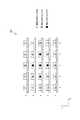
具体的には、各光ファイバー113の長さのグルーピングについて、図9を参照しながら説明する。図9は、固体光源111の光出射面側から固体光源111を見た図である。すなわち、図9は、固体光源111の配列を示す図である。 Specifically, the grouping of the lengths of the
図9に示すように、各固体光源111の配置位置は、X軸及びY軸によって定義される。すなわち、各固体光源111の配置位置は、(X,Y)で表される。変更例3では、バンドル部114の配置位置は、(X,Y)=(3,3)であるケースについて例示する。 As shown in FIG. 9, the arrangement position of each solid
ここで、各固体光源111は、光ファイバー113の長さがL1であるグループ#1、光ファイバー113の長さがL2(>L1)であるグループ#2及び光ファイバー113の長さがL3(>L2)であるグループ#3にグルーピングされる。 Here, in each solid-
このように、各固体光源111は、(3,3)の配置位置を中心として、同心円上にグルーピングされる。(3,3)の配置位置、すなわち、バンドル部114の配置位置に固体光源111の配置位置が近いほど、光ファイバー113の長さが短いグループに固体光源111がグルーピングされる。 Thus, the solid
[第2実施形態]
以下において、第2実施形態について、図面を参照しながら説明する。以下においては、第1実施形態との相違点について主として説明する。[Second Embodiment]
Hereinafter, the second embodiment will be described with reference to the drawings. In the following, differences from the first embodiment will be mainly described.
具体的には、第1実施形態では、投写型映像表示装置100が壁面に設けられた投写面300に映像光を投写するケースについて例示した。これに対して、第2実施形態では、投写型映像表示装置100が床面に設けられた投写面300に映像光を投写するケースについて例示する(床面投写)。このようなケースにおける筐体200の配置を床面投写配置と称する。 Specifically, in the first embodiment, the case where the
(投写型映像表示装置の構成)
以下において、第2実施形態に係る投写型映像表示装置の構成について、図面を参照しながら説明する。図10は、第2実施形態に係る投写型映像表示装置100を側方から見た図である。(Configuration of projection display device)
Hereinafter, the configuration of the projection display apparatus according to the second embodiment will be described with reference to the drawings. FIG. 10 is a side view of the
図10に示すように、投写型映像表示装置100は、床面に設けられた投写面300に映像光を投写する(床面投写)。第2実施形態では、投写面300と略平行な第1配置面は床面410である。第1配置面に略垂直な第2配置面は壁面420である。 As shown in FIG. 10, the
第2実施形態では、投写面300に平行な水平方向を“幅方向”と称する。投写面300の法線方向を“高さ方向”と称する。幅方向及び高さ方向の双方に直交する方向を“奥行き方向”と称する。 In the second embodiment, a horizontal direction parallel to the
第2実施形態では、筐体200は、第1実施形態と同様に、略直方体形状を有する。奥行き方向における筐体200のサイズ及び高さ方向における筐体200のサイズは、幅方向における筐体200のサイズよりも小さい。高さ方向における筐体200のサイズは、反射ミラー(図2に示す凹面ミラー152)から投写面300までの投写距離と略等しい。幅方向において、筐体200のサイズは、投写面300のサイズと略等しい。奥行き方向において、筐体200のサイズは、壁面420から投写面300までの距離に応じて定められる。 In the second embodiment, the
投写面側側壁210は、投写面300と略平行な第1配置面(第2実施形態では、床面410)と対向する板状の部材である。前面側側壁220は、投写面側側壁210の反対側に設けられた板状の部材である。天板240は、底面板230の反対側に設けられた板状の部材である。底面板230は、投写面300と略平行な第1配置面以外の第2配置面(第2実施形態では、壁面420)と対向する板状の部材である。第1側面側側壁250及び第2側面側側壁260は、幅方向において筐体200の両端を形成する板状の部材である。 The projection
[その他の実施形態]
本発明は上述した実施形態によって説明したが、この開示の一部をなす論述及び図面は、この発明を限定するものであると理解すべきではない。この開示から当業者には様々な代替実施形態、実施例及び運用技術が明らかとなろう。[Other Embodiments]
Although the present invention has been described with reference to the above-described embodiments, it should not be understood that the descriptions and drawings constituting a part of this disclosure limit the present invention. From this disclosure, various alternative embodiments, examples and operational techniques will be apparent to those skilled in the art.
第1実施形態では、筐体200が配置される壁面420上に投写面300が設けられるが、実施形態はこれに限定されるものではない。投写面300は、筐体200から離れる方向において、壁面420よりも奥まった位置に設けられてもよい。 In the first embodiment, the
第2実施形態では、筐体200が配置される床面410上に投写面300が設けられるが、実施形態はこれに限定されるものではない。投写面300は、床面410よりも低い位置に設けられてもよい。 In the second embodiment, the
第1実施形態、変更例1〜第2実施形態では、各ユニットの配置を例示したに過ぎない。また、筐体200の幅方向において筐体200の略中央に投写ユニット150が配置されていれば、各ユニット(光源ユニット110、電源ユニット120及び冷却ユニット130)の配置は自由である。なお、奥行き方向における筐体200のサイズ及び高さ方向における筐体200のサイズは、幅方向における筐体200のサイズよりも小さいことに留意すべきである。 In the first embodiment and the first and second modified examples, the arrangement of each unit is merely illustrated. Further, as long as the
実施形態では、光変調素子として、DMD(Digital Micromirror Device)を例示したに過ぎない。光変調素子は、透過型の液晶パネルであってもよく、反射型の液晶パネルであってもよい。 In the embodiment, a DMD (Digital Micromirror Device) is merely illustrated as the light modulation element. The light modulation element may be a transmissive liquid crystal panel or a reflective liquid crystal panel.
変更例2では、各固体光源111に接続された各光ファイバー113の長さは段毎に異なるが、実施形態はこれに限定されるものではない。具体的には、複数の段に設けられた固体光源111に接続された全光ファイバー113の長さが同じであってもよい。このようなケースでは、固体光源111とバンドル部114との距離を段毎に変更するように、各段に設けられた載置台118がスライド可能に構成されていることが好ましい。 In the second modification, the length of each
10…ロッドインテグレータ、21〜23…レンズ、31〜35…ミラー、40…レンズ、50…プリズム、60…プリズム、70…プリズム、80…プリズム、90…プリズム、100…投写型映像表示装置、110…光源ユニット、111…固体光源、112…ヘッド、113…光ファイバー、114…バンドル部、118…載置台、119…レール、120…電源ユニット、130…冷却ユニット、131…冷却ジャケット、140…色分離合成ユニット、141…第1ユニット、142…第2ユニット、150…投写ユニット、151…投写レンズ群、152…凹面ミラー、160…投写面側凹部、、170…前面側凸部、180…天板凹部、181…傾斜面、190…ケーブル端子、200…筐体、210…投写面側側壁、220…前面側側壁、230…底面板、240…天板、250…第1側面側側壁、260…第2側面側側壁、300…投写面、410…床面、420…壁面、500…DMD DESCRIPTION OF SYMBOLS 10 ... Rod integrator, 21-23 ... Lens, 31-35 ... Mirror, 40 ... Lens, 50 ... Prism, 60 ... Prism, 70 ... Prism, 80 ... Prism, 90 ... Prism, 100 ... Projection type image display apparatus, 110 DESCRIPTION OF SYMBOLS ... Light source unit, 111 ... Solid light source, 112 ... Head, 113 ... Optical fiber, 114 ... Bundle part, 118 ... Mounting stand, 119 ... Rail, 120 ... Power supply unit, 130 ... Cooling unit, 131 ... Cooling jacket, 140 ... Color separation Combining unit 141 ... first unit 142 ...
Claims (4)
Translated fromJapanese前記複数の固体光源のそれぞれは、複数の光ファイバーのそれぞれに接続されており、
前記複数の光ファイバーは、バンドル部で束ねられており、
前記バンドル部で束ねられる前記複数の光ファイバーから出射される光は、前記光変調素子に導かれ、
前記複数の光ファイバーのそれぞれの長さは同じであることを特徴とする投写型映像表示装置。A light source unit including a plurality of solid light sources, a light modulation element that modulates light emitted from the plurality of solid light sources, and a projection unit that projects light emitted from the light modulation elements onto a projection surface. A projection image display device comprising:
Each of the plurality of solid state light sources is connected to each of a plurality of optical fibers,
The plurality of optical fibers are bundled in a bundle part,
Light emitted from the plurality of optical fibers bundled in the bundle part is guided to the light modulation element,
Each of the plurality of optical fibers has the same length.
前記複数のグループ毎に分類された光ファイバーの長さは、前記複数のグループ毎に同じであることを特徴とする請求項1に記載の投写型映像表示装置。The plurality of optical fibers are classified into a plurality of groups,
2. The projection display apparatus according to claim 1, wherein lengths of the optical fibers classified into the plurality of groups are the same for the plurality of groups.
Priority Applications (2)
| Application Number | Priority Date | Filing Date | Title |
|---|---|---|---|
| JP2009083208AJP2010237311A (en) | 2009-03-30 | 2009-03-30 | Projection video display device |
| US12/559,565US20100073637A1 (en) | 2008-09-19 | 2009-09-15 | Illuminating device and projection display device |
Applications Claiming Priority (1)
| Application Number | Priority Date | Filing Date | Title |
|---|---|---|---|
| JP2009083208AJP2010237311A (en) | 2009-03-30 | 2009-03-30 | Projection video display device |
Publications (1)
| Publication Number | Publication Date |
|---|---|
| JP2010237311Atrue JP2010237311A (en) | 2010-10-21 |
Family
ID=43091707
Family Applications (1)
| Application Number | Title | Priority Date | Filing Date |
|---|---|---|---|
| JP2009083208APendingJP2010237311A (en) | 2008-09-19 | 2009-03-30 | Projection video display device |
Country Status (1)
| Country | Link |
|---|---|
| JP (1) | JP2010237311A (en) |
Cited By (13)
| Publication number | Priority date | Publication date | Assignee | Title |
|---|---|---|---|---|
| US9882100B2 (en) | 2015-08-20 | 2018-01-30 | Panasonic Intellectual Property Management Co., Ltd. | Light-emitting device having surface structure for limiting directional angle of light |
| US9880336B2 (en) | 2014-02-28 | 2018-01-30 | Panasonic Intellectual Property Management Co., Ltd. | Light-emitting device including photoluminescent layer |
| US9890912B2 (en) | 2014-02-28 | 2018-02-13 | Panasonic Intellectual Property Management Co., Ltd. | Light-emitting apparatus including photoluminescent layer |
| US9899577B2 (en) | 2015-06-08 | 2018-02-20 | Panasonic Intellectual Property Management Co., Ltd. | Light-emitting apparatus including photoluminescent layer |
| US10012780B2 (en) | 2014-02-28 | 2018-07-03 | Panasonic Intellectual Property Management Co., Ltd. | Light-emitting device including photoluminescent layer |
| US10031276B2 (en) | 2015-03-13 | 2018-07-24 | Panasonic Intellectual Property Management Co., Ltd. | Display apparatus including photoluminescent layer |
| US10094522B2 (en) | 2016-03-30 | 2018-10-09 | Panasonic Intellectual Property Management Co., Ltd. | Light-emitting device having photoluminescent layer |
| US10113712B2 (en) | 2015-03-13 | 2018-10-30 | Panasonic Intellectual Property Management Co., Ltd. | Light-emitting device including photoluminescent layer |
| US10115874B2 (en) | 2015-06-08 | 2018-10-30 | Panasonic Intellectual Property Management Co., Ltd. | Light-emitting device including photoluminescent layer |
| US10182702B2 (en) | 2015-03-13 | 2019-01-22 | Panasonic Intellectual Property Management Co., Ltd. | Light-emitting apparatus including photoluminescent layer |
| US10359155B2 (en) | 2015-08-20 | 2019-07-23 | Panasonic Intellectual Property Management Co., Ltd. | Light-emitting apparatus |
| USRE49093E1 (en) | 2015-03-13 | 2022-06-07 | Panasonic Intellectual Property Management Co., Ltd. | Light-emitting apparatus including photoluminescent layer |
| USRE50041E1 (en) | 2015-08-20 | 2024-07-16 | Panasonic Intellectual Property Management Co., Ltd. | Light-emitting apparatus |
Citations (2)
| Publication number | Priority date | Publication date | Assignee | Title |
|---|---|---|---|---|
| JPH09508476A (en)* | 1994-01-31 | 1997-08-26 | エス・ディー・エル・インコーポレイテッド | Laser lighting display system |
| JP2008009304A (en)* | 2006-06-30 | 2008-01-17 | Nikon Corp | Illumination device and projection display device using the same |
- 2009
- 2009-03-30JPJP2009083208Apatent/JP2010237311A/enactivePending
Patent Citations (2)
| Publication number | Priority date | Publication date | Assignee | Title |
|---|---|---|---|---|
| JPH09508476A (en)* | 1994-01-31 | 1997-08-26 | エス・ディー・エル・インコーポレイテッド | Laser lighting display system |
| JP2008009304A (en)* | 2006-06-30 | 2008-01-17 | Nikon Corp | Illumination device and projection display device using the same |
Cited By (13)
| Publication number | Priority date | Publication date | Assignee | Title |
|---|---|---|---|---|
| US9880336B2 (en) | 2014-02-28 | 2018-01-30 | Panasonic Intellectual Property Management Co., Ltd. | Light-emitting device including photoluminescent layer |
| US9890912B2 (en) | 2014-02-28 | 2018-02-13 | Panasonic Intellectual Property Management Co., Ltd. | Light-emitting apparatus including photoluminescent layer |
| US10012780B2 (en) | 2014-02-28 | 2018-07-03 | Panasonic Intellectual Property Management Co., Ltd. | Light-emitting device including photoluminescent layer |
| US10113712B2 (en) | 2015-03-13 | 2018-10-30 | Panasonic Intellectual Property Management Co., Ltd. | Light-emitting device including photoluminescent layer |
| USRE49093E1 (en) | 2015-03-13 | 2022-06-07 | Panasonic Intellectual Property Management Co., Ltd. | Light-emitting apparatus including photoluminescent layer |
| US10031276B2 (en) | 2015-03-13 | 2018-07-24 | Panasonic Intellectual Property Management Co., Ltd. | Display apparatus including photoluminescent layer |
| US10182702B2 (en) | 2015-03-13 | 2019-01-22 | Panasonic Intellectual Property Management Co., Ltd. | Light-emitting apparatus including photoluminescent layer |
| US9899577B2 (en) | 2015-06-08 | 2018-02-20 | Panasonic Intellectual Property Management Co., Ltd. | Light-emitting apparatus including photoluminescent layer |
| US10115874B2 (en) | 2015-06-08 | 2018-10-30 | Panasonic Intellectual Property Management Co., Ltd. | Light-emitting device including photoluminescent layer |
| US10359155B2 (en) | 2015-08-20 | 2019-07-23 | Panasonic Intellectual Property Management Co., Ltd. | Light-emitting apparatus |
| US9882100B2 (en) | 2015-08-20 | 2018-01-30 | Panasonic Intellectual Property Management Co., Ltd. | Light-emitting device having surface structure for limiting directional angle of light |
| USRE50041E1 (en) | 2015-08-20 | 2024-07-16 | Panasonic Intellectual Property Management Co., Ltd. | Light-emitting apparatus |
| US10094522B2 (en) | 2016-03-30 | 2018-10-09 | Panasonic Intellectual Property Management Co., Ltd. | Light-emitting device having photoluminescent layer |
Similar Documents
| Publication | Publication Date | Title |
|---|---|---|
| JP2010237311A (en) | Projection video display device | |
| JP5914808B2 (en) | Light source device and projection display device | |
| CN2929756Y (en) | System and device for synthesizing light paths of multiple colored light sources through common synthesizing channel | |
| US20110128510A1 (en) | Projection image display apparatus | |
| US8113661B2 (en) | Projection-type display apparatus | |
| US11156910B2 (en) | Projection display apparatus including a reflection device including reflection regions and transmission regions | |
| JP2015184303A (en) | Light source optical device and projector | |
| WO2011040479A1 (en) | Optical unit, projection image display device, and diffusion optical element | |
| WO2006088735A2 (en) | Method and apparatus for combining light paths of like-colored light sources | |
| JP5162901B2 (en) | Projection display device and optical unit | |
| JP2015121597A (en) | Projection device | |
| JP2010256558A (en) | Projection type video display | |
| JP5317787B2 (en) | Projection display device | |
| JP2011141507A (en) | Projection type video display device | |
| JP2008181776A (en) | Light source device and projector | |
| JP2010266838A (en) | Projection type video display device | |
| JP6493721B2 (en) | Light source optical device and projector | |
| JP2011180281A (en) | Projection video display device, and diffusion optical element | |
| JP5261269B2 (en) | Projection display device | |
| KR101713342B1 (en) | Projection system | |
| JP2007133161A (en) | Optical system for illumination and projector using the same | |
| JP5378025B2 (en) | Projection display device | |
| JP2010250274A (en) | Projection image display apparatus | |
| WO2014171135A1 (en) | Projection type image display device | |
| JP2011100093A (en) | Projection image display device and diffusion optical element |
Legal Events
| Date | Code | Title | Description |
|---|---|---|---|
| A621 | Written request for application examination | Free format text:JAPANESE INTERMEDIATE CODE: A621 Effective date:20120227 | |
| A131 | Notification of reasons for refusal | Free format text:JAPANESE INTERMEDIATE CODE: A131 Effective date:20130212 | |
| A977 | Report on retrieval | Free format text:JAPANESE INTERMEDIATE CODE: A971007 Effective date:20130213 | |
| A02 | Decision of refusal | Free format text:JAPANESE INTERMEDIATE CODE: A02 Effective date:20130625 |