JP2010235041A - Vehicular air cleaning control device - Google Patents
Vehicular air cleaning control deviceDownload PDFInfo
- Publication number
- JP2010235041A JP2010235041AJP2009087470AJP2009087470AJP2010235041AJP 2010235041 AJP2010235041 AJP 2010235041AJP 2009087470 AJP2009087470 AJP 2009087470AJP 2009087470 AJP2009087470 AJP 2009087470AJP 2010235041 AJP2010235041 AJP 2010235041A
- Authority
- JP
- Japan
- Prior art keywords
- deodorizing
- sensor
- fragrance
- occupant
- sensor node
- Prior art date
- Legal status (The legal status is an assumption and is not a legal conclusion. Google has not performed a legal analysis and makes no representation as to the accuracy of the status listed.)
- Pending
Links
- 238000004140cleaningMethods0.000titleclaimsabstractdescription7
- 238000004891communicationMethods0.000claimsabstractdescription77
- 230000001877deodorizing effectEffects0.000claimsabstractdescription67
- 238000002156mixingMethods0.000claimsabstractdescription42
- 238000001514detection methodMethods0.000claimsabstractdescription30
- 239000003205fragranceSubstances0.000claimsdescription70
- 238000000034methodMethods0.000claimsdescription29
- 238000004332deodorizationMethods0.000claimsdescription23
- CBENFWSGALASAD-UHFFFAOYSA-NOzoneChemical compound[O-][O+]=OCBENFWSGALASAD-UHFFFAOYSA-N0.000claimsdescription21
- 230000008569processEffects0.000claimsdescription18
- 238000012545processingMethods0.000claimsdescription17
- 238000004364calculation methodMethods0.000claimsdescription8
- 238000004887air purificationMethods0.000claimsdescription6
- 230000001954sterilising effectEffects0.000claimsdescription6
- 238000004659sterilization and disinfectionMethods0.000claimsdescription6
- 150000002500ionsChemical class0.000claimsdescription4
- 238000002360preparation methodMethods0.000claims1
- 235000019645odorNutrition0.000description7
- 235000008694Humulus lupulusNutrition0.000description6
- 230000005540biological transmissionEffects0.000description6
- 238000010586diagramMethods0.000description6
- 230000006870functionEffects0.000description6
- 230000005484gravityEffects0.000description4
- 238000005259measurementMethods0.000description4
- 238000004378air conditioningMethods0.000description3
- 230000000694effectsEffects0.000description3
- 230000008859changeEffects0.000description2
- 238000004590computer programMethods0.000description2
- 238000002347injectionMethods0.000description2
- 239000007924injectionSubstances0.000description2
- 239000000203mixtureSubstances0.000description2
- 238000003860storageMethods0.000description2
- 238000012795verificationMethods0.000description2
- 241000282326Felis catusSpecies0.000description1
- 238000006424Flood reactionMethods0.000description1
- 230000008901benefitEffects0.000description1
- 238000007664blowingMethods0.000description1
- 238000009472formulationMethods0.000description1
- 238000009434installationMethods0.000description1
- 238000004519manufacturing processMethods0.000description1
- 230000007246mechanismEffects0.000description1
- 239000007921spraySubstances0.000description1
- 238000012360testing methodMethods0.000description1
Images


Landscapes
- Air-Conditioning For Vehicles (AREA)
- Disinfection, Sterilisation Or Deodorisation Of Air (AREA)
Abstract
Description
Translated fromJapanese本発明は、車室内の脱臭・消臭及び芳香を発生させる車両用空気清浄制御装置に関する。 The present invention relates to a vehicle air cleaning control device that generates deodorization / deodorization and fragrance in a passenger compartment.
車室内を空気清浄する技術として、特許文献1には、覚醒用の香りを含む複数の香りを送出可能な芳香装置を備え、香りの使用目的に応じて風の吹き出し状態を変えることで、居眠り運転等を防止する技術が記載されている。また、特許文献2には、香りを車室内に放出する芳香発生手段と、ドライバの注意が前方対象物に集中している注意過多状態と、周辺環境に向いている漫然状態との何れであるかを判定するドライバ状態判定手段と、を備え、ドライバ状態が上記漫然状態を維持又は上記注意過多状態から上記漫然状態に移行するよう、上記ドライバ判定手段によって判定されたドライバの状態に応じて上記芳香発生手段による車室内への香り放出を制御する技術が記載されている。 As a technique for purifying the interior of a vehicle,
しかしながら、上記特許文献1では、居眠り運転防止のために、ドライバを覚醒させることを目的として香りを発生させているが、覚醒状態であってもドライバの状態は異なっているため、例えば、先行車等の前方対象物だけに集中している状態よりも、周辺環境にも注意を向けている状態に維持させることが望ましい。しかしながら、このための芳香の発生は行っておらず、ドライバの状態を走行環境に適応した状態に維持されていない。 However, in
また、上記特許文献2では、ドライバごとに香りに嗜好があるため、その効果にバラツキがある。特に、不特定多数のドライバが使用するレンタカーやカーシェアリング用車両においては、顕著である。また、芳香発生後、残香が滞留したり、他の匂いと混ざって悪臭となる場合もある。 Moreover, in the said
本発明は、上述の課題に鑑みてなされ、その目的は、乗員ごとの嗜好に合った芳香を発生させることができる技術を実現することである。 This invention is made | formed in view of the above-mentioned subject, The objective is to implement | achieve the technique which can generate the fragrance according to the preference for every passenger | crew.
上述の課題を解決し、目的を達成するために、本発明に係る第1の形態は、所定の調合比で芳香を生成する芳香発生手段と、乗員の着座状態を検出する着座状態検出手段と、車室内の脱臭・消臭処理を行う脱臭・消臭手段と、前記乗員の着座状態に基づいて、前記芳香発生手段と前記脱臭・消臭手段を制御する制御手段と、前記芳香の調合比が登録された調合テーブルを記憶するサーバと通信する通信手段と、を有し、前記制御手段は、前記通信手段を介して前記サーバの調合テーブルに登録された着座乗員ごとの調合比を取得し、当該調合比に基づいて前記芳香発生手段を制御する。この形態によれば、乗員ごとの嗜好に合った芳香を発生させることができる。 In order to solve the above-described problems and achieve the object, a first embodiment according to the present invention includes a fragrance generating unit that generates a fragrance at a predetermined mixing ratio, and a seating state detection unit that detects a seating state of an occupant. Deodorizing / deodorizing means for performing deodorizing / deodorizing treatment in the passenger compartment, control means for controlling the fragrance generating means and the deodorizing / deodorizing means based on the seated state of the occupant, and the mixing ratio of the fragrance Communication means communicating with a server that stores the blending table registered, and the control means obtains the blending ratio for each seated occupant registered in the blending table of the server via the communication means. The fragrance generating means is controlled based on the blending ratio. According to this aspect, it is possible to generate a fragrance that matches the preference of each occupant.
また、本発明に係る第2の形態では、前記制御手段は、前記芳香発生手段により芳香を発生する前に、前記脱臭・消臭処理を行うように前記脱臭・消臭手段を制御する。この形態によれば、残香や悪臭を除去し、芳香効果をより一層高めることができる。 Moreover, in the 2nd form which concerns on this invention, the said control means controls the said deodorizing and deodorizing means so that the said deodorizing and deodorizing process may be performed before generating a fragrance by the said fragrance generating means. According to this embodiment, residual aroma and bad odor can be removed, and the aroma effect can be further enhanced.
本発明に係る第3の形態では、前記脱臭・消臭手段は、車室内の除菌度を検出するセンサを用いた除菌モードと、車室内の脱臭度を検出するセンサを用いた脱臭モードとを有し、前記制御手段は、所定のイオン又はオゾン濃度を維持する目標時間を算出し、当該目標時間となるように前記センサの検出結果に基づいて前記脱臭・消臭手段をフィードバック制御する。この形態によれば、脱臭・消臭の程度に応じた適切な処理を行うことができる。 In the third embodiment according to the present invention, the deodorizing / deodorizing means includes a sterilization mode using a sensor for detecting the degree of sterilization in the passenger compartment, and a deodorization mode using a sensor for detecting the degree of odor removal in the passenger compartment. The control means calculates a target time for maintaining a predetermined ion or ozone concentration, and feedback-controls the deodorizing / deodorizing means based on the detection result of the sensor so that the target time is reached. . According to this form, it is possible to perform an appropriate process according to the degree of deodorization / deodorization.
本発明に係る第4の形態では、前記着座状態検出手段は、着座の有無を検出するセンサ部と、前記センサ部による検出値を記憶するメモリ部と、前記検出値を演算処理する演算処理部と、前記検出値を送信する通信部とを有するセンサノードを構成し、複数の前記センサノードが車室内の異なる位置に配置される。この形態によれば、乗員の着座位置を精度良く検出し、乗員ごとの嗜好に合った芳香を発生させることができる。 In the fourth embodiment according to the present invention, the seating state detection means includes a sensor unit that detects the presence or absence of seating, a memory unit that stores a detection value by the sensor unit, and an arithmetic processing unit that performs arithmetic processing on the detection value. And a communication unit that transmits the detection value, and a plurality of the sensor nodes are arranged at different positions in the vehicle interior. According to this aspect, it is possible to accurately detect the seating position of the occupant and generate fragrance that matches the preference of each occupant.
本発明に係る第5の形態では、前記センサノードは、着座乗員が所持する通信端末と通信することにより乗員ごとの識別情報を取得し、前記制御手段は、前記通信手段を介して前記サーバから取得した乗員ごとの識別情報に対応する調合比に基づいて芳香を発生するように前記芳香発生手段を制御する。この形態によれば、乗員の識別を精度良く行い、乗員ごとの嗜好に合った芳香を発生させることができる。 In a fifth aspect according to the present invention, the sensor node obtains identification information for each occupant by communicating with a communication terminal possessed by a seated occupant, and the control means receives information from the server via the communication means. The fragrance generating means is controlled so as to generate fragrance based on the blending ratio corresponding to the acquired identification information for each occupant. According to this aspect, it is possible to accurately identify an occupant and generate an aroma that suits the preference of each occupant.
本発明に係る第6の形態では、前記調合テーブルの調合比が視認可能な図柄で登録されており、乗員が前記図柄を選択することで前記調合テーブルの調合比を登録する登録手段を更に有する。この形態によれば、イメージしにくい芳香の調合比を容易に編集・更新できる。 In the sixth embodiment according to the present invention, the blending ratio of the blending table is registered as a visually recognizable symbol, and further includes registration means for registering the blending ratio of the blending table by selecting the symbol by the occupant. . According to this form, it is possible to easily edit and update the mixing ratio of fragrances that are difficult to imagine.
本発明に係る第7の形態では、前記制御手段は、前記着座検出手段により乗員が非着座状態であることを検出した場合に前記脱臭・消臭処理を行うように前記消臭・脱臭手段を制御する。この形態によれば、乗員不在時に消臭・脱臭処理を行うことができる。 In a seventh aspect according to the present invention, the control means controls the deodorization / deodorization means to perform the deodorization / deodorization process when the seating detection means detects that the occupant is in a non-sitting state. Control. According to this embodiment, it is possible to perform deodorization / deodorization treatment when no occupant is present.
本発明に係る第8の形態は、前記調合テーブルが前記サーバから前記通信端末へ送信され、当該通信端末により編集・更新が可能である。この形態によれば、時間的又は場所的な都合に縛られずに、データの編集及び更新を行うことができる。 According to an eighth aspect of the present invention, the blending table is transmitted from the server to the communication terminal, and can be edited and updated by the communication terminal. According to this aspect, data can be edited and updated without being restricted by time or place.
本発明によれば、乗員ごとの嗜好に合った芳香を発生させることができる。 ADVANTAGE OF THE INVENTION According to this invention, the fragrance suitable for the preference for every passenger | crew can be generated.
以下に、本発明の実施の形態について添付図面を参照して詳細に説明する。尚、以下に説明する実施の形態は、本発明の実現手段としての一例であり、本発明は、その趣旨を逸脱しない範囲で下記実施形態を修正又は変形したものに適用可能である。また、後述する各実施形態の制御に対応するコンピュータプログラムや当該コンピュータプログラムが格納された記憶媒体を、車両に搭載されたコンピュータに供給して、当該コンピュータが記憶媒体に格納されたプログラムコードを読み出して実行するようにしてもよい。 Hereinafter, embodiments of the present invention will be described in detail with reference to the accompanying drawings. The embodiment described below is an example as means for realizing the present invention, and the present invention can be applied to a modified or modified embodiment described below without departing from the spirit of the present invention. In addition, a computer program corresponding to the control of each embodiment to be described later and a storage medium storing the computer program are supplied to a computer mounted on the vehicle, and the computer reads out the program code stored in the storage medium. May be executed.
[実施形態1]
先ず、実施形態1について説明する。[Embodiment 1]
First, the first embodiment will be described.
<システム構成>
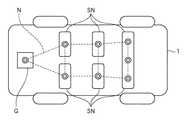
図1及び図2は本発明に係る実施形態の車両用空気清浄制御装置を搭載した車両を模式的に示す平面図及び側面図、図3はセンサノードの機能ブロック図、図4はゲートウェイポイントの機能ブロック図である。<System configuration>
1 and 2 are a plan view and a side view schematically showing a vehicle equipped with a vehicle air purification control apparatus according to an embodiment of the present invention, FIG. 3 is a functional block diagram of a sensor node, and FIG. It is a functional block diagram.
図1乃至図4に示すように、車両1には、複数のセンサノードSN及びゲートウェイポイントGが配置されている。センサノードSNは車室内の各座席の着座位置に対応するシートクッション部2、ルーフ部3及びフロア部4に配置されている。また、車室内のインパネ部の空調ダクト付近並びに1,2列目のシートバック部背面には芳香発生装置10及び脱臭・消臭装置20が配置されている。センサノードSNはコイン大の大きさで比較的薄いものであり、車室内の様々な部位に取り付け可能である。これらセンサノードSNは、互いに無線通信によるセンサネットワーク(図1の符号N)を形成する。 As shown in FIGS. 1 to 4, a plurality of sensor nodes SN and gateway points G are arranged in the
ゲートウェイポイントGは、例えばカーナビゲーションシステムに搭載される制御ユニットであり、CPU5、メモリ6及び通信IF(インタフェース)7a〜7f等を有する。通信インタフェース7a〜7cは、ゲートウェイポイントGと芳香発生装置10、脱臭・消臭装置20及び空調装置30との有線又は無線による通信を制御する。通信インタフェース7dはサーバ40との通信ネットワーク8を介した通信を制御する。更に、通信インタフェース7eは、無線通信により各センサノードSNと情報(信号)の送受信を行う。また、通信インタフェース7fは、犬や猫などのペットや首輪等に埋め込まれたICタグ9を無線により読み取り、ペット固有の個体識別番号等を取得する。 The gateway point G is a control unit mounted in, for example, a car navigation system, and includes a
CPU5は、各通信インタフェース7a〜7fを介して受信した情報に基づき、後述する芳香発生装置10及び脱臭・消臭装置20の目標制御量を算出し、着座する乗員ごとの嗜好に合うように芳香発生装置10及び脱臭・消臭装置20を制御する。メモリ6には、各車載機器の制御プログラムや図10や図14に示す関連付けテーブル6aが記憶されている。 The
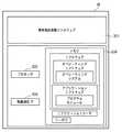
図3に示すように、各センサノードSNには、例えばボタン電池のような電源101、CPUであるプロセッサ102、及びセンサノードSNに内蔵され又はその外部に取り付けられる複数のセンサ103a〜103dを有する。センサは、例えば湿度センサ103a、温度センサ103b、圧力センサ103c、オゾンセンサ103dを含む。圧力センサ103cは、乗員の着座を検知する着座センサとして機能する。また、センサノードSNは、他のセンサノードSN、携帯電話等の通信端末M及びゲートウェイポイントGと通信する無線通信インタフェース104を有する。 As shown in FIG. 3, each sensor node SN includes a
また、センサノードSNには、メモリ105が搭載されており、各センサ103a〜103dの検出値を処理したり、通信端末Mや他のセンサノードSNとの信号の入出力を行うためのプログラムが内蔵されたソフトウェア105aが記憶されている。ソフトウェア105aは、オペレーティングソフトウェア105bと、アプリケーションソフトウェア105cとからなり、オペレーティングソフトウェア105bには、オペレーティングシステム105dが含まれ、アプリケーションソフトウェア105cにはプログラムモジュール105eが含まれる。また、メモリ105には、アプリケーションデータ105fが記憶されている。 In addition, the
センサノードSNのメモリ105は、各センサノードSNごとのセンサ103a〜103dによる検出値を記憶し、プロセッサ102は、各センサ103a〜103dの検出値を読み出して演算処理する。 The
ゲートウェイポイントGのCPU5は、各センサノードSNから受信した情報やサーバ40に記憶されたデータベース(以下、DB)41〜43に基づいて芳香発生装置10及び脱臭・消臭装置20を制御するための目標制御量を算出する。なお、上記DB41〜43の一部を、センサノードSNのメモリ105やゲートウェイポイントGのメモリ6に格納してもよい。 The
上記ゲートウェイポイントGのCPU5は、算出された目標制御量が得られるように芳香発生装置10、脱臭・消臭装置20及び空調装置30を制御する。また、算出された目標制御量は、センサノードSNのメモリ又は、ゲートウェイポイントGのメモリ6に記憶される。 The
センサノードSNの通信方式として、例えば、「ZigBee」といわれるものがある。これは、規格が「IEEE802.15.4」、伝送速度(bps)が「250K」、利用周波数帯が「2.4GHz(全世界)、868MHz(欧州)、915MHz(米国)」、伝送距離が「最大10-75m」、消費電力(通信)が「<60mW」のものである。これ以外にも、方式として、「微弱無線」、「特定小電力無線」、「Bluetooth」、「UWB」などの他の方式もある。 As a communication method of the sensor node SN, for example, there is one called “ZigBee”. The standard is “IEEE802.15.4”, the transmission speed (bps) is “250K”, the frequency band used is “2.4GHz (worldwide), 868MHz (Europe), 915MHz (US)”, and the transmission distance is “up to 10”. -75m "and power consumption (communication) is" <60mW ". In addition to this, there are other methods such as “weak wireless”, “specific low power wireless”, “Bluetooth”, and “UWB”.
ゲートウェイポイントGのメモリ6には、センサノードSNや実施形態2で後述する通信端末Mとの信号の入出力を行うためのプログラムが内蔵されたソフトウェアが記憶されている。ソフトウェアは、図3に示したセンサノードSNと同様に、オペレーティングソフトウェアと、アプリケーションソフトウェアとからなり、オペレーティングソフトウェアには、オペレーティングシステムが含まれ、アプリケーションソフトウェアにはプログラムモジュールが含まれる。また、メモリには、アプリケーションデータが記憶されている。 The
ゲートウェイポイントGは、各センサノードSN及び通信ネットワーク8から得られる情報を集中管理すると共に車載機器、例えば、上記装置10〜30のほか、カーナビゲーションシステム、電動シート装置、パワーウィンドウなどを制御する。また、ゲートウェイポイントGで使用する情報を、PC201や通信端末202を介して車外のサーバ40に情報を蓄積することも可能である。 The gateway point G centrally manages information obtained from each sensor node SN and the
次に、上述したセンサネットワークの概念について説明する。 Next, the concept of the sensor network described above will be described.
上述したように、センサノードSNには、プロセッサ、センサ、メモリ、通信インタフェースが内蔵されており、各センサにより得られた情報を保持できるほか、無線により他のセンサノードSNに送信することができる。そのような機能により、あるセンサノードSNは、他のセンサノードSNの情報、即ち、他のセンサノードSNが有するセンサにより得られた情報や記憶されている情報を得る。このようにして、複数のセンサノードSNがネットワークでつながっており(図4参照)、仮に1つのセンサノードSNが故障しても、他のセンサノードSNでネットワークを形成することができる。これにより、配線でつながっている車内LANとは異なり、配線の不要なネットワークを形成する。また、ある位置のセンサノードSNの情報を他のセンサノードSNの情報と共に多角的に得ることができる。このセンサネットワークによれば、例えば、センサノードSNにより各シートごとに着座乗員を検出し、芳香発生装置10や脱臭・消臭装置20を着座乗員ごとの嗜好に合わせて制御することができる。 As described above, the sensor node SN includes a processor, a sensor, a memory, and a communication interface, and can store information obtained by each sensor and can transmit to other sensor nodes SN wirelessly. . With such a function, a certain sensor node SN obtains information on other sensor nodes SN, that is, information obtained by sensors included in other sensor nodes SN and stored information. In this way, a plurality of sensor nodes SN are connected by a network (see FIG. 4), and even if one sensor node SN fails, a network can be formed by other sensor nodes SN. This forms a network that does not require wiring, unlike in-vehicle LANs that are connected by wiring. In addition, the information of the sensor node SN at a certain position can be obtained from various angles together with the information of the other sensor nodes SN. According to this sensor network, for example, the seat occupant can be detected for each seat by the sensor node SN, and the
次に、芳香発生装置10及び脱臭・消臭装置20について説明する。 Next, the
図5(a)に示すように、芳香発生装置10と脱臭・消臭装置20とは一体化されて、空調ダクトの経路途中に配置される。芳香発生装置10は、複数の香料噴霧ノズル11から複数種類の香料を所定の調合比で噴射することにより、空調ダクトを介して車室内へ芳香を放出する。各香料噴射ノズル11は、ピエゾ素子を用いたインクジェット方式と同様の原理を適用して、香料ごとにノズルから所定量の香料を噴射する。また、芳香発生装置10は、通信ネットワーク8を介してサーバ40から取得した芳香DBに登録された着座乗員ごとの調合比に基づいて各香料噴射ノズル11を駆動して、所望の芳香を生成する。 As shown to Fig.5 (a), the
脱臭・消臭装置20は、イオン/オゾン発生部21からイオン/オゾンを発生させて、車室内を脱臭/消臭する機能を有し、芳香発生装置10の近傍に設けられて、芳香発生前の悪臭や残香を除去する脱臭・消臭処理を行う。脱臭・消臭装置20は、除菌度を検出するセンサを用いた除菌モードと、脱臭度を検出するセンサを用いた脱臭モードとを有し、図5(b)に示すように、ゲートウェイポイントGのCPU5が所定のオゾン濃度を維持する目標時間を算出し、当該目標時間となるように上記各センサノードSNのオゾンセンサ103dの検出値に基づいてフィードバック制御される。これにより、脱臭・消臭の程度に応じた適切な処理を行うことができる。 The deodorization /
なお、図6に示すように、芳香発生装置10と脱臭・消臭装置20と制御ユニット50とを持ち運び可能な単体の機器とし、ゲートウェイポイントGやセンサノードSNと無線で通信可能に構成することで、車室内の任意の場所(例えば、各シートバック部背面)に設置して着座乗員ごとに芳香発生処理や脱臭・消臭処理を行うことができる。なお、制御ユニット50は、図3と類似する構成を有し、プロセッサ、操作部、メモリ、無線通信インタフェースが搭載されている。 As shown in FIG. 6, the
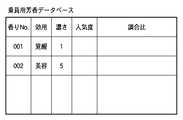
サーバ40は、通信ネットワーク8を介してゲートウェイポイントGや他のPC201や通信端末(スマートキー、携帯電話、PDAなど)202と通信する。ここで、サーバ40は、香料の調合比が登録された調合テーブルを記憶する乗員用芳香DB41(図7)及びペット用芳香DB42(図8)と、フィードバック制御用のオゾン濃度目標値が登録されたオゾン濃度DB43(図9)を有する。 The
乗員用芳香DB41には、図7に示すように、乗員固有の識別番号としての香りNo.ごとに、効用、濃さ、人気度、香料の調合比が登録されている。 As shown in FIG. 7, the
ペット用芳香DB42には、図8に示すように、ペット固有の識別番号としての香りNo.ごとに、効用、種別、人気度、香料の調合比が登録されている。 In the
オゾン濃度DB43には、図9に示すように、脱臭・消臭処理の目的ごとに、必要なオゾン濃度や条件が登録されている。 As shown in FIG. 9, necessary ozone concentrations and conditions are registered in the
また、ゲートウェイポイントGのメモリ6には、図10に示すように、乗員の体重と香りNo.とを関連付けたテーブル6a及びペット固有の個体識別番号としてのICタグ9と香りNo.とを関連付けたテーブルとが記憶されている。ゲートウェイポイントGは、センサノードSNにより検出される着座乗員の体重に対応する香りNo.をサーバ40に送信して該当する調合比を取得し、以下の制御を実行する。 Further, in the
<処理フロー>
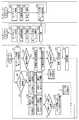
図11は実施形態1のゲートウェイポイント及びセンサノードの各処理を示すフローチャートである。<Processing flow>
FIG. 11 is a flowchart illustrating processing of the gateway point and the sensor node according to the first embodiment.
(センサノードSN)
図11において、S21では、各センサノードSNは上述したセンサネットワークを形成する。ここでは、各センサノードSNが他のセンサノードSNを認識して、自律的にネットワークを形成する。このセンサネットワークにおいて、新たなセンサノードSNが設置された場合、自律的にそのセンサノードSNをセンサネットワーク内に追加したり、また、あるセンサノードSNがセンサネットワークから無くなった場合、自律的にそのセンサノードSNをセンサネットワークから削除するというアドホック機能を有する。(Sensor node SN)
In FIG. 11, in S21, each sensor node SN forms the above-described sensor network. Here, each sensor node SN recognizes another sensor node SN and autonomously forms a network. In this sensor network, when a new sensor node SN is installed, the sensor node SN is autonomously added to the sensor network, or when a certain sensor node SN disappears from the sensor network, the sensor node SN is autonomously added. It has an ad hoc function of deleting the sensor node SN from the sensor network.
次に、S22では、後述する「受信したビーコンノードの重心計算」又は「受信したビーコンノードのホップ数計算」により、各センサノードSNの位置検出処理を行う。なお、予め位置が分かっているような場合、例えば、位置が固定されているシートやルーフにセンサノードSNが設置されている場合には、その設置位置を予めセンサノードSNのメモリ等に登録しておいてもよい。また、位置検出処理を一度行った後に、メモリに位置を記憶させておき、再度位置検出処理を行うときには、そのメモリに記憶された位置を設定するようにしてもよい。 Next, in S22, the position detection processing of each sensor node SN is performed by “calculation of the center of gravity of the received beacon node” or “calculation of the hop number of the received beacon node” described later. When the position is known in advance, for example, when the sensor node SN is installed on a seat or roof where the position is fixed, the installation position is registered in advance in the memory of the sensor node SN. You may keep it. Further, after the position detection process is performed once, the position may be stored in the memory, and when the position detection process is performed again, the position stored in the memory may be set.
次に、S23、S24では、各センサノードSNの位置データ、及び、各センサノードSNの各センサ103a〜103dによる検出値を複数のセンサノード間で送受信し且つそれらのデータをメモリ105に記憶する。送受信は各ノードの無線通信インタフェース104で行う。 Next, in S23 and S24, the position data of each sensor node SN and the detection values of the
次に、S25では、他のセンサノードSNの中継処理を行う。ここでは、各センサノードSNは、他のセンサノードSNへの通信経路(ルーティング)を自律的に確立し、他のセンサノードSNから送信されてきたデータを他のセンサノードSNに中継する。これは、マルチホップ機能という機能である。 Next, in S25, the relay process of another sensor node SN is performed. Here, each sensor node SN autonomously establishes a communication path (routing) to another sensor node SN, and relays data transmitted from the other sensor node SN to the other sensor node SN. This is a function called a multi-hop function.
ここで、S23におけるセンサノードSN(又は、実施形態2で述べる通信端末M)の位置を検出する方法について説明する。 Here, a method for detecting the position of the sensor node SN (or the communication terminal M described in the second embodiment) in S23 will be described.
これは、通信端末Mを所持するユーザが乗車した場合やセンサノードSNがシートに取り付けられている場合、シート自体が多様なアレンジで位置が変更される場合に、シート位置の変更されたセンサノードSNの位置を正確に検出するものである。 This is because the sensor node whose seat position has been changed when the user carrying the communication terminal M gets on the vehicle, when the sensor node SN is attached to the seat, or when the seat itself is changed in various arrangements. The position of SN is accurately detected.
先ず、第1の方法である、「受信したビーコンノードの重心計算」について説明する。 First, the first method “calculation of the center of gravity of a received beacon node” will be described.
ここで、ビーコンノードとは、所定の位置情報を送受信することができるセンサノードSN又は通信端末Mであり、ノードとは、位置の分かっていないセンサノードSNや通信端末Mであり、ランドマークとは、位置が分かっていて所定の位置情報を送受信することができるセンサノードSNや通信端末Mである。ビーコンとは、位置情報を含む電波信号である。 Here, a beacon node is a sensor node SN or communication terminal M that can transmit and receive predetermined position information, and a node is a sensor node SN or communication terminal M whose position is unknown, Is a sensor node SN or a communication terminal M that has a known position and can transmit and receive predetermined position information. A beacon is a radio signal including position information.
この重心計算によるCentroid(重心)測定では、位置を予め分かっているランドマークが、定期的に自らの位置情報を含んだビーコンをブロードキャストで近隣のノードに送信する。ランドマークからのビーコンは、球状に送信されると仮定しており、受信電波強度を考慮しないものになっている。さらに、ランドマークが多く存在していることを想定している。位置が分かっていないノードは、ビーコンに含まれる位置情報から周りに存在するランドマークの位置を知ることができる。N台のランドマークの位置(Xi,Yi)が取得できた場合、下記の式1で重心(Xest,Yest)を計算する。In Centroid (centroid) measurement by centroid calculation, a landmark whose position is known in advance periodically transmits a beacon including its own position information to neighboring nodes. The beacon from the landmark is assumed to be transmitted in a spherical shape, and does not consider the received radio wave intensity. Furthermore, it is assumed that there are many landmarks. A node whose position is not known can know the positions of landmarks existing around from the position information included in the beacon. When the positions (Xi, Yi) of N landmarks can be acquired, the center of gravity (Xest ,Yest ) is calculated by the following

次に、第2の方法である、「受信したビーコンノードのホップ数計算」について説明する。
Next, the second method “calculation of hop count of received beacon node” will be described.
ここで、ノードとは、位置の分かっていないセンサノードSNや通信端末Mであり、ランドマークとは、位置が分かっていて所定の位置情報を送受信することができるセンサノードSNや通信端末Mである。 Here, a node is a sensor node SN or a communication terminal M whose position is not known, and a landmark is a sensor node SN or a communication terminal M whose position is known and capable of transmitting and receiving predetermined position information. is there.
このDV-Hop測定では、ランドマークからのホップ数と1ホップの平均距離の情報から、各ノードからランドマークまでの距離を見積もる。3台以上のランドマークからの距離を見積り、多角測定により自らの位置を算出する仕組みになっている。 In this DV-Hop measurement, the distance from each node to the landmark is estimated from information on the number of hops from the landmark and the average distance of one hop. It is a mechanism that estimates the distance from three or more landmarks and calculates its position by polygon measurement.
先ず、第1ステップとして、各ノードは、センサネットワーク内のランドマークからのホップ数を知る(ホップカウンタを参照する)。ランドマークは自分の位置情報を含んだバケットをフラッディングする。また、このバケットには、中継する度にカウントされるホップカウンタが含まれている。 First, as a first step, each node knows the number of hops from a landmark in the sensor network (refers to a hop counter). The landmark floods the bucket containing its location information. Further, this bucket includes a hop counter that is counted each time relaying.
次に、第2ステップとして、ランドマークは1ホップの平均距離を近隣ノードに知らせる。一度しか“1ホップの平均距離”バケットを中継しない制御フラッディングを利用する。第1ステップで得られたホップ数と1ホップの平均距離を掛け合わせることによりランドマークまでの距離を算出する。 Next, as a second step, the landmark informs neighboring nodes of the average distance of one hop. Uses control flooding that relays the "one hop average distance" bucket only once. The distance to the landmark is calculated by multiplying the number of hops obtained in the first step and the average distance of one hop.
次に、第3ステップとして、3台以上のランドマークとの距離を算出して多角測定により位置測定する。1ホップの平均距離の算出方法を説明する。あるランドマークがフラッディングしたバケットは、他のランドマークにも到着している。ランドマークは、自分の座標と他のランドマークの座標から、2地点間の物理的な距離を計算することができる。さらに、そのランドマークまでのホップ数(h)が分かっているため、物理的な距離をホップ数で割った値が1ホップの平均距離のサンプルとして計算する。このサンプル取得処理を他の全てのランドマークに対して行うことにより、最終的にサンプルを平均化して1ホップの距離が計算できる。これは、以下の式2により計算できる。 Next, as a third step, the distance from three or more landmarks is calculated, and the position is measured by polygon measurement. A method for calculating the average distance of one hop will be described. A bucket flooded by one landmark has arrived at another landmark. A landmark can calculate the physical distance between two points from its own coordinates and the coordinates of other landmarks. Further, since the number of hops (h) to the landmark is known, a value obtained by dividing the physical distance by the number of hops is calculated as a sample of the average distance of one hop. By performing this sample acquisition process on all other landmarks, the samples can be averaged to calculate a one-hop distance. This can be calculated by
(ゲートウェイポイントG)
ゲートウェイポイントGでは、S1において、S24において各センサノードSNから送信された各ノードSNの位置データ、及び、各センサによる検出値を受信しメモリ6に記憶する。
(Gateway point G)
In the gateway point G, in S1, the position data of each node SN transmitted from each sensor node SN in S24 and the detection value by each sensor are received and stored in the
次に、S2では、各センサノードSNの圧力センサ103cによる検出値により着座した乗員の有無を判定する。 Next, in S2, the presence / absence of a seated occupant is determined based on the detection value of the
そして、着座乗員有りと判定された場合、S3では、各センサノードSNの圧力センサ103cによる検出値により着座した乗員の着座シート位置を推定する。 If it is determined that there is a seated occupant, in S3, the seated seat position of the seated occupant is estimated based on the detection value of the
次に、S4では、ゲートウェイポイントGは、メモリ6に登録された関連付けテーブル6aから着座乗員の体重(圧力)に応じた香りNo.を割り出し、サーバ40にアクセスし、乗員用芳香DB41(図7)から着座乗員の香りNo.に応じた調合比を取得する。なお、圧力センサ103cによる検出値に代えて、乗員が所持している通信端末Mや車内に設けられた操作部から着座している乗員固有の識別番号を直接入力してもよい。 Next, in S4, the gateway point G obtains the scent No. corresponding to the weight (pressure) of the seated occupant from the association table 6a registered in the
次に、S5では、芳香制御中又は芳香の変更があるか判定する。そして、S5で芳香制御中又は芳香に変更がないならば、S6で脱臭・消臭制御を実行する。その後、S7では、S4で取得した調合比に基づき芳香制御を実行する。このように、芳香を発生させる前に消臭・脱臭制御を行うことにより、残香や悪臭を除去し、芳香効果をより一層高めることができる。 Next, in S5, it is determined whether there is a fragrance control or a fragrance change. If the fragrance is being controlled in S5 or if there is no change in the fragrance, deodorizing / deodorizing control is executed in S6. Thereafter, in S7, aroma control is executed based on the blending ratio acquired in S4. Thus, by performing deodorizing / deodorizing control before generating fragrance, residual odor and bad odor can be removed and the fragrance effect can be further enhanced.
一方、S5で芳香制御中又は芳香に変更があるならば、S6をスキップし、S7で芳香制御を実行する。この脱臭・消臭制御は、図5(b)で述べたようにオゾンセンサ103dによるフィードバック制御を実行する。 On the other hand, if the fragrance is being controlled or the fragrance is changed in S5, S6 is skipped, and the fragrance control is executed in S7. In this deodorization / deodorization control, feedback control by the
次に、S2で着座乗員なしと判定された場合、S8ではICタグ9からペット固有の個体識別番号を受信したか判定する。 Next, if it is determined in S2 that there is no seated occupant, it is determined in S8 whether a pet-specific individual identification number has been received from the
そして、ペット固有の個体識別番号を受信した場合、S9では、サーバ40にアクセスし、オゾン濃度DB43(図9)からペット有り且つ無人条件における目標オゾン濃度を取得する。 When the individual identification number unique to the pet is received, in S9, the
次に、S10、S11では、各センサノードSNのオゾンセンサ103dによる検出値に基づいて、S9で取得した目標オゾン濃度に到達するまでフィードバック制御を実行する。その後、S12では、ゲートウェイポイントGは、メモリ6に登録された関連付けテーブル6aからICタグ9の個体識別番号に応じた香りNo.を割り出し、サーバ40にアクセスし、ペット用芳香DB42(図8)からペットの香りNo.に応じた調合比を取得し、芳香制御を実行する。 Next, in S10 and S11, feedback control is executed until the target ozone concentration acquired in S9 is reached based on the detection value by the
なお、S8でペット固有の個体識別番号を受信しない場合、S13では、サーバ40にアクセスし、オゾン濃度DB43(図9)からペット無し且つ無人条件における目標オゾン濃度を取得する。 If the individual identification number unique to the pet is not received in S8, the
次に、S14では、各センサノードSNのオゾンセンサ103dによる検出値に基づいて、S13で取得した目標オゾン濃度に到達するまでフィードバック制御を実行する。 Next, in S14, feedback control is executed until the target ozone concentration acquired in S13 is reached based on the detection value by the
上記実施形態によれば、乗員ごとの嗜好に合った芳香を発生させることができる。 According to the embodiment, it is possible to generate a fragrance that suits the preference of each occupant.
[実施形態2]
次に、実施形態2として、乗員が所持する通信端末Mから取得したユーザID及び位置データに基づく処理について説明する。[Embodiment 2]
Next, as
図12は乗員が所持している通信端末Mの機能ブロック図である。 FIG. 12 is a functional block diagram of the communication terminal M possessed by the passenger.
図12に示すように、通信端末Mとしての携帯電話には、携帯電話基盤ミドルウェア301、CPUであるプロセッサ302、複数のセンサノードSNと無線通信可能な無線通信インタフェース303、及びメモリ304を有する。メモリ304には、センサノードSNとの信号の入出力を行うためのプログラムが内蔵されたソフトウェアが記憶されている。ソフトウェアは、オペレーティングソフトウェアと、アプリケーションソフトウェアとからなり、オペレーティングソフトウェアには、オペレーティングシステムが含まれ、アプリケーションソフトウェアにはプログラムモジュールが含まれる。また、メモリには、アプリケーションデータ、ユーザIDが記憶されている。この通信端末Mも、上述した複数のセンサノードSNと無線通信によりセンサネットワークを形成する。 As shown in FIG. 12, the mobile phone as the communication terminal M includes a mobile
なお、本実施形態のセンサノードSNは、図3の構成から圧力センサ103cを省略した構成とする。 Note that the sensor node SN of the present embodiment has a configuration in which the
また、ゲートウェイポイントGのメモリ6には、図14に示すように、ユーザIDと香りNo.とを関連付けたテーブルやICタグ9と香りNo.とを関連付けたテーブルとが記憶されている。 Further, in the
<処理フロー>
図13は実施形態2のゲートウェイポイント、センサノード及び通信端末の各処理を示すフローチャートである。<Processing flow>
FIG. 13 is a flowchart illustrating processing of the gateway point, the sensor node, and the communication terminal according to the second embodiment.
(センサノードSN)
センサノードSNでの処理は、通信端末Mの中継処理のほか、図11のS21〜S25での処理と同様であるので説明を省略する。(Sensor node SN)
The processing at the sensor node SN is the same as the processing at S21 to S25 in FIG.
(通信端末M)
図13において、S31で通信端末Mを所持するユーザが乗車し、S32でセンサネットワークに接続されると、先ずセンサノードSNによる中継処理によりゲートウェイポイントGへユーザIDを送信する(S33)。(Communication terminal M)
In FIG. 13, when a user carrying the communication terminal M gets on in S31 and is connected to the sensor network in S32, first, the user ID is transmitted to the gateway point G by the relay process by the sensor node SN (S33).
次に、S34、S35では、ゲートウェイポイントGからユーザIDの照合結果を受信し、ユーザIDがゲートウェイポイントGのメモリ6に未登録ならば、S36で仮ユーザIDアドレスの自動割当を行った後、登録済みならば、S36を行わずに、S37で送受信テスト&経路設定を行い、S38では、通信端末Mの位置検出処理を実行する。この位置検出処理は、図11で述べた「受信したビーコンノードの重心計算」又は「受信したビーコンノードのホップ数計算」による。 Next, in S34 and S35, if the user ID verification result is received from the gateway point G and the user ID is not registered in the
次に、S39では、通信端末Mの位置データを各センサノードSNの中継によりゲートウェイポイントGに送信する。なお、通信端末Mにも芳香DBに関するデータを登録しておき、位置データと共に送信するようにしてもよい。 Next, in S39, the position data of the communication terminal M is transmitted to the gateway point G through the relay of each sensor node SN. Data relating to the fragrance DB may be registered in the communication terminal M and transmitted together with the position data.
(ゲートウェイポイントG)
以下では、図11と同様の処理には同一の符号を付して説明を省略する。(Gateway point G)
In the following, the same processes as those in FIG.
ゲートウェイポイントGは、S1で各センサノードSNの位置データ及び各センサによる検出値を受信しメモリ6に記憶した後、S41で、通信端末MからユーザIDを受信する。 The gateway point G receives the position data of each sensor node SN and the detection value by each sensor in S1 and stores them in the
次に、S2で着座乗員有りと判定された場合、S42では、S41で受信したユーザIDが、ゲートウェイポイントGのメモリ6に登録されたユーザIDと香りNo.の関連付けテーブルに登録済みのIDと照合し、照合結果を通信端末Mに送信する。 Next, when it is determined in S2 that there is a seated occupant, in S42, the user ID received in S41 is the user ID registered in the
次に、S43では、通信端末Mから位置データを受信する。S44では、ユーザIDと位置データから着座した乗員の着座シート位置を推定する。 Next, in S43, position data is received from the communication terminal M. In S44, the seated seat position of the seated passenger is estimated from the user ID and the position data.
その後、S4では、ユーザIDに応じた香りNo.を割り出し、サーバ40にアクセスし、乗員用芳香DB41(図7)から着座乗員ごとの香りNo.に応じた調合比を取得する。 Thereafter, in S4, the fragrance No. corresponding to the user ID. The scent No. for each seated occupant is accessed from the occupant fragrance DB 41 (FIG. 7). The blending ratio according to is acquired.
<データの更新処理>
ユーザは上記通信端末Mを使用してサーバ40に登録された各DBの編集や更新を行うことができる。以下、上記通信端末Mによるデータの編集・更新処理について説明する。図15は、通信端末によるデータの編集・更新処理を示すフローチャートである。<Data update process>
The user can edit and update each DB registered in the
(通信端末M)
図15において、通信端末Mは、S51でサーバ40に対して送信要求を行い、S52で所望のDBを受信する。次に、S53で受信したDBについてデータを編集・更新して、S54でサーバ40へ送信する。ここで、DBの調合比が絵や色等の視認可能な図柄で登録されており、ユーザは図柄を選択する等して編集・更新を行うことができる。これにより、イメージしにくい芳香の調合比等を容易に編集・更新できる。(Communication terminal M)
In FIG. 15, the communication terminal M makes a transmission request to the
(サーバ40)
サーバ40は、S61で通信端末Mからデータの送信要求を受信すると、S62で指定されたデータを送信する。次に、S63で通信端末Mからデータの更新要求と更新されたデータを受信すると、S64で受信したデータにDBを更新する。(Server 40)
When the
これにより、時間的又は場所的な都合に縛られずに、データの編集及び更新を行うことができる。 As a result, data can be edited and updated without being restricted by time or place.
なお、上記通信端末Mを用いてゲートウェイポイントGのメモリ6に記憶されたデータを更新してもよい。 Note that the data stored in the
Claims (8)
Translated fromJapanese乗員の着座状態を検出する着座状態検出手段と、
車室内の脱臭・消臭処理を行う脱臭・消臭手段と、
前記乗員の着座状態に基づいて、前記芳香発生手段と前記脱臭・消臭手段を制御する制御手段と、
前記芳香の調合比が登録された調合テーブルを記憶するサーバと通信する通信手段と、を有し、
前記制御手段は、前記通信手段を介して前記サーバの調合テーブルに登録された着座乗員ごとの調合比を取得し、当該調合比に基づいて前記芳香発生手段を制御することを特徴とする車両用空気清浄制御装置。A fragrance generating means for generating a fragrance at a predetermined mixing ratio;
A seating state detection means for detecting the seating state of the occupant;
Deodorizing / deodorizing means for deodorizing / deodorizing the passenger compartment,
Control means for controlling the fragrance generating means and the deodorizing / deodorizing means based on the sitting state of the occupant;
Communication means for communicating with a server for storing a blending table in which the blending ratio of the fragrance is registered,
The control means acquires the blending ratio for each seated occupant registered in the blending table of the server via the communication means, and controls the fragrance generating means based on the blending ratio. Air cleaning control device.
前記制御手段は、所定のイオン又はオゾン濃度を維持する目標時間を算出し、当該目標時間となるように前記センサの検出結果に基づいて前記脱臭・消臭手段をフィードバック制御することを特徴とする請求項1又は2に記載の車両用空気清浄制御装置。The deodorizing / deodorizing means has a sterilization mode using a sensor for detecting the degree of sterilization in the passenger compartment, and a deodorization mode using a sensor for detecting the degree of odor removal in the passenger compartment.
The control means calculates a target time for maintaining a predetermined ion or ozone concentration, and feedback-controls the deodorizing / deodorizing means based on a detection result of the sensor so as to be the target time. The vehicle air purification control device according to claim 1 or 2.
複数の前記センサノードが車室内の異なる位置に配置されることを特徴とする請求項1乃至3のいずれか1項に記載の車両用空気清浄制御装置。The seating state detection means includes a sensor unit for detecting presence / absence of sitting, a memory unit for storing a detection value by the sensor unit, a calculation processing unit for calculating the detection value, and a communication unit for transmitting the detection value A sensor node having
The vehicle air cleaning control apparatus according to any one of claims 1 to 3, wherein the plurality of sensor nodes are arranged at different positions in a vehicle interior.
前記制御手段は、前記通信手段を介して前記サーバから取得した乗員ごとの識別情報に対応する調合比に基づいて芳香を発生するように前記芳香発生手段を制御することを特徴とする請求項4に記載の車両用空気清浄制御装置。The sensor node acquires identification information for each occupant by communicating with a communication terminal possessed by a seated occupant,
The said control means controls the said fragrance generating means to generate | occur | produce a fragrance based on the preparation ratio corresponding to the identification information for every passenger | crew acquired from the said server via the said communication means. The air purification control apparatus for vehicles described in 2.
乗員が前記図柄を選択することで前記調合テーブルの調合比を登録する登録手段を更に有することを特徴とする請求項4に記載の車両用空気清浄制御装置。The blending ratio of the blending table is registered in a visible pattern,
The vehicular air cleaning control apparatus according to claim 4, further comprising a registration unit that registers a blending ratio of the blending table when an occupant selects the symbol.
Priority Applications (1)
| Application Number | Priority Date | Filing Date | Title |
|---|---|---|---|
| JP2009087470AJP2010235041A (en) | 2009-03-31 | 2009-03-31 | Vehicular air cleaning control device |
Applications Claiming Priority (1)
| Application Number | Priority Date | Filing Date | Title |
|---|---|---|---|
| JP2009087470AJP2010235041A (en) | 2009-03-31 | 2009-03-31 | Vehicular air cleaning control device |
Publications (1)
| Publication Number | Publication Date |
|---|---|
| JP2010235041Atrue JP2010235041A (en) | 2010-10-21 |
Family
ID=43089787
Family Applications (1)
| Application Number | Title | Priority Date | Filing Date |
|---|---|---|---|
| JP2009087470APendingJP2010235041A (en) | 2009-03-31 | 2009-03-31 | Vehicular air cleaning control device |
Country Status (1)
| Country | Link |
|---|---|
| JP (1) | JP2010235041A (en) |
Cited By (13)
| Publication number | Priority date | Publication date | Assignee | Title |
|---|---|---|---|---|
| JP2012105707A (en)* | 2010-11-15 | 2012-06-07 | Hiroo Takei | Deodorizer-smoke extinguisher |
| US10029654B2 (en) | 2016-04-13 | 2018-07-24 | Ford Global Technologies, Llc | Enhanced vehicle cleaning |
| WO2019077998A1 (en)* | 2017-10-19 | 2019-04-25 | 本田技研工業株式会社 | Vehicle air conditioning management device, vehicle air conditioning management system, and vehicle air conditioning management method |
| JP2019097933A (en)* | 2017-12-04 | 2019-06-24 | アルパイン株式会社 | Automatic deodorant control device and automatic deodorant control method in vehicle |
| JP2019194519A (en)* | 2013-07-10 | 2019-11-07 | チャンドラー, ジョン サーストンCHANDLER, John Thurston | Bias setting of aroma supply system |
| WO2020039223A1 (en)* | 2018-08-20 | 2020-02-27 | 日産自動車株式会社 | Vehicle management system, onboard system, and vehicle management method |
| JP2021062729A (en)* | 2019-10-11 | 2021-04-22 | トヨタ紡織株式会社 | Air-conditioning system |
| FR3102713A1 (en)* | 2019-11-06 | 2021-05-07 | Psa Automobiles Sa | DEVICE AND METHOD FOR CHECKING HYGIENE IN A INTERIOR OF A SHARED VEHICLE |
| CN113119695A (en)* | 2021-04-08 | 2021-07-16 | 一汽奔腾轿车有限公司 | Method for realizing personalized function of fragrance system |
| WO2022044457A1 (en)* | 2020-08-25 | 2022-03-03 | アルプスアルパイン株式会社 | Ozone treatment apparatus and notification apparatus |
| JP2022041856A (en)* | 2020-08-31 | 2022-03-11 | テイ・エス テック株式会社 | In-car system |
| JP2023087276A (en)* | 2021-12-13 | 2023-06-23 | コニカミノルタ株式会社 | disinfection equipment system |
| JP2023091695A (en)* | 2021-12-20 | 2023-06-30 | 研能科技股▲ふん▼有限公司 | Method for notifying in-car air contamination |
Citations (11)
| Publication number | Priority date | Publication date | Assignee | Title |
|---|---|---|---|---|
| JPH01176440U (en)* | 1988-05-31 | 1989-12-15 | ||
| JPH04141A (en)* | 1990-04-16 | 1992-01-06 | Hitachi Ltd | Air conditioning system |
| JPH10253096A (en)* | 1997-03-14 | 1998-09-25 | Kawasaki Setsubi Kogyo Kk | Air conditioner equipped with sterilization and deodorization means |
| JP2004113383A (en)* | 2002-09-25 | 2004-04-15 | Pixen Inc | Aroma diffusion apparatus |
| JP2004168074A (en)* | 2002-11-15 | 2004-06-17 | Denso Corp | Air purifying device for vehicle |
| JP2004196111A (en)* | 2002-12-18 | 2004-07-15 | Denso Corp | Air conditioner for vehicle |
| JP2005143629A (en)* | 2003-11-12 | 2005-06-09 | Nec Fielding Ltd | System, method and program for relaxation |
| JP2005523775A (en)* | 2002-05-01 | 2005-08-11 | スマト・エア・インコーポレイテッド | Air purification, deodorization and sterilization equipment using ozone |
| JP2006282084A (en)* | 2005-04-01 | 2006-10-19 | Denso Corp | Air component feeder for vehicle |
| WO2007105694A1 (en)* | 2006-03-13 | 2007-09-20 | Pioneer Corporation | Awakening retainer and method for retaining awakening and computer program for retaining awakening |
| JP2008195177A (en)* | 2007-02-13 | 2008-08-28 | Fuji Heavy Ind Ltd | Fragrance component supply device for vehicles |
- 2009
- 2009-03-31JPJP2009087470Apatent/JP2010235041A/enactivePending
Patent Citations (11)
| Publication number | Priority date | Publication date | Assignee | Title |
|---|---|---|---|---|
| JPH01176440U (en)* | 1988-05-31 | 1989-12-15 | ||
| JPH04141A (en)* | 1990-04-16 | 1992-01-06 | Hitachi Ltd | Air conditioning system |
| JPH10253096A (en)* | 1997-03-14 | 1998-09-25 | Kawasaki Setsubi Kogyo Kk | Air conditioner equipped with sterilization and deodorization means |
| JP2005523775A (en)* | 2002-05-01 | 2005-08-11 | スマト・エア・インコーポレイテッド | Air purification, deodorization and sterilization equipment using ozone |
| JP2004113383A (en)* | 2002-09-25 | 2004-04-15 | Pixen Inc | Aroma diffusion apparatus |
| JP2004168074A (en)* | 2002-11-15 | 2004-06-17 | Denso Corp | Air purifying device for vehicle |
| JP2004196111A (en)* | 2002-12-18 | 2004-07-15 | Denso Corp | Air conditioner for vehicle |
| JP2005143629A (en)* | 2003-11-12 | 2005-06-09 | Nec Fielding Ltd | System, method and program for relaxation |
| JP2006282084A (en)* | 2005-04-01 | 2006-10-19 | Denso Corp | Air component feeder for vehicle |
| WO2007105694A1 (en)* | 2006-03-13 | 2007-09-20 | Pioneer Corporation | Awakening retainer and method for retaining awakening and computer program for retaining awakening |
| JP2008195177A (en)* | 2007-02-13 | 2008-08-28 | Fuji Heavy Ind Ltd | Fragrance component supply device for vehicles |
Cited By (19)
| Publication number | Priority date | Publication date | Assignee | Title |
|---|---|---|---|---|
| JP2012105707A (en)* | 2010-11-15 | 2012-06-07 | Hiroo Takei | Deodorizer-smoke extinguisher |
| JP2019194519A (en)* | 2013-07-10 | 2019-11-07 | チャンドラー, ジョン サーストンCHANDLER, John Thurston | Bias setting of aroma supply system |
| US10029654B2 (en) | 2016-04-13 | 2018-07-24 | Ford Global Technologies, Llc | Enhanced vehicle cleaning |
| WO2019077998A1 (en)* | 2017-10-19 | 2019-04-25 | 本田技研工業株式会社 | Vehicle air conditioning management device, vehicle air conditioning management system, and vehicle air conditioning management method |
| JP2019097933A (en)* | 2017-12-04 | 2019-06-24 | アルパイン株式会社 | Automatic deodorant control device and automatic deodorant control method in vehicle |
| JP7085003B2 (en) | 2018-08-20 | 2022-06-15 | 日産自動車株式会社 | Vehicle management system, in-vehicle system and vehicle management method |
| WO2020039223A1 (en)* | 2018-08-20 | 2020-02-27 | 日産自動車株式会社 | Vehicle management system, onboard system, and vehicle management method |
| CN112601673A (en)* | 2018-08-20 | 2021-04-02 | 日产自动车株式会社 | Vehicle management system, vehicle-mounted system, and vehicle management method |
| US12240472B2 (en) | 2018-08-20 | 2025-03-04 | Nissan Motor Co., Ltd. | Vehicle management system and vehicle management method |
| JPWO2020039223A1 (en)* | 2018-08-20 | 2021-09-02 | 日産自動車株式会社 | Vehicle management system, in-vehicle system and vehicle management method |
| CN112601673B (en)* | 2018-08-20 | 2024-01-09 | 日产自动车株式会社 | Vehicle management system and vehicle management method |
| JP2021062729A (en)* | 2019-10-11 | 2021-04-22 | トヨタ紡織株式会社 | Air-conditioning system |
| FR3102713A1 (en)* | 2019-11-06 | 2021-05-07 | Psa Automobiles Sa | DEVICE AND METHOD FOR CHECKING HYGIENE IN A INTERIOR OF A SHARED VEHICLE |
| JPWO2022044457A1 (en)* | 2020-08-25 | 2022-03-03 | ||
| WO2022044457A1 (en)* | 2020-08-25 | 2022-03-03 | アルプスアルパイン株式会社 | Ozone treatment apparatus and notification apparatus |
| JP2022041856A (en)* | 2020-08-31 | 2022-03-11 | テイ・エス テック株式会社 | In-car system |
| CN113119695A (en)* | 2021-04-08 | 2021-07-16 | 一汽奔腾轿车有限公司 | Method for realizing personalized function of fragrance system |
| JP2023087276A (en)* | 2021-12-13 | 2023-06-23 | コニカミノルタ株式会社 | disinfection equipment system |
| JP2023091695A (en)* | 2021-12-20 | 2023-06-30 | 研能科技股▲ふん▼有限公司 | Method for notifying in-car air contamination |
Similar Documents
| Publication | Publication Date | Title |
|---|---|---|
| JP2010235041A (en) | Vehicular air cleaning control device | |
| JP6812955B2 (en) | Position determination system | |
| CN105263114B (en) | Home mode judgment method, control device and the system of Intelligent housing | |
| JP2019209827A (en) | Air conditioner for vehicle | |
| JP4770684B2 (en) | Inter-vehicle communication system | |
| CN103158618B (en) | The rear rider entertainment systems of projection | |
| JP5133810B2 (en) | Driving diagnosis device and driving diagnosis system | |
| WO2012157095A1 (en) | Air-condition remote control system for vehicle, server, mobile terminal, and vehicle | |
| CN108725353A (en) | Control module activation for monitoring the vehicle for being in ignition switch off state | |
| US20090248244A1 (en) | Onboard device control apparatus | |
| JP6028467B2 (en) | Vehicle air conditioning control device and system | |
| JP6519953B2 (en) | In-vehicle device | |
| JP2009205367A (en) | Driving support system | |
| JP2013084143A (en) | On-vehicle communication device | |
| JP2010234905A (en) | Vehicular air conditioner and control method for the vehicular air conditioner | |
| JP2010112931A (en) | Reset system, and mobile device, communication apparatus and method used in the system | |
| JP2007269109A (en) | Power management system | |
| CN108437911A (en) | Vehicle entertainment system | |
| JP2019064357A (en) | Air conditioning control system | |
| JP2012201220A (en) | Air conditioning system | |
| WO2019077998A1 (en) | Vehicle air conditioning management device, vehicle air conditioning management system, and vehicle air conditioning management method | |
| JP5038451B2 (en) | Control system, control method, automobile | |
| JP5093595B2 (en) | In-vehicle device controller | |
| US11584197B2 (en) | Air-conditioner control system responsive to an electronic settlement, and computer-readable storage medium that stores therein air-conditioning control program responsive to an electronic settlement | |
| JP5093594B2 (en) | In-vehicle device controller |
Legal Events
| Date | Code | Title | Description |
|---|---|---|---|
| RD03 | Notification of appointment of power of attorney | Free format text:JAPANESE INTERMEDIATE CODE: A7423 Effective date:20101001 | |
| RD04 | Notification of resignation of power of attorney | Free format text:JAPANESE INTERMEDIATE CODE: A7424 Effective date:20101001 | |
| A621 | Written request for application examination | Free format text:JAPANESE INTERMEDIATE CODE: A621 Effective date:20120123 | |
| RD02 | Notification of acceptance of power of attorney | Free format text:JAPANESE INTERMEDIATE CODE: A7422 Effective date:20120312 | |
| A521 | Written amendment | Free format text:JAPANESE INTERMEDIATE CODE: A523 Effective date:20130118 | |
| A131 | Notification of reasons for refusal | Free format text:JAPANESE INTERMEDIATE CODE: A131 Effective date:20130305 | |
| A02 | Decision of refusal | Free format text:JAPANESE INTERMEDIATE CODE: A02 Effective date:20130625 |