JP2010233915A - Bone plate and bone plate system - Google Patents
Bone plate and bone plate systemDownload PDFInfo
- Publication number
- JP2010233915A JP2010233915AJP2009086965AJP2009086965AJP2010233915AJP 2010233915 AJP2010233915 AJP 2010233915AJP 2009086965 AJP2009086965 AJP 2009086965AJP 2009086965 AJP2009086965 AJP 2009086965AJP 2010233915 AJP2010233915 AJP 2010233915A
- Authority
- JP
- Japan
- Prior art keywords
- screw
- bone plate
- bone
- longitudinal direction
- axis
- Prior art date
- Legal status (The legal status is an assumption and is not a legal conclusion. Google has not performed a legal analysis and makes no representation as to the accuracy of the status listed.)
- Pending
Links
- 210000000988bone and boneAnatomy0.000titleclaimsabstractdescription137
- 238000010079rubber tappingMethods0.000claimsdescription17
- 230000000149penetrating effectEffects0.000claimsdescription3
- 210000002303tibiaAnatomy0.000abstractdescription25
- 239000002184metalSubstances0.000abstractdescription5
- 239000000843powderSubstances0.000abstractdescription5
- 208000003947Knee OsteoarthritisDiseases0.000description5
- 230000004048modificationEffects0.000description3
- 238000012986modificationMethods0.000description3
- 238000010586diagramMethods0.000description2
- 239000000463materialSubstances0.000description2
- 238000000034methodMethods0.000description2
- 201000008482osteoarthritisDiseases0.000description2
- 230000002093peripheral effectEffects0.000description2
- 230000007423decreaseEffects0.000description1
- 210000003275diaphysisAnatomy0.000description1
- 230000000694effectsEffects0.000description1
- 230000012447hatchingEffects0.000description1
- 210000003127kneeAnatomy0.000description1
- 230000007704transitionEffects0.000description1
- 210000000689upper legAnatomy0.000description1
Images


Landscapes
- Surgical Instruments (AREA)
Abstract
Description
Translated fromJapanese本発明は、骨プレートおよび骨プレートシステムに関するものである。 The present invention relates to bone plates and bone plate systems.
従来、骨折した大腿骨や頸骨を含む長骨の一部を固定する骨プレートとして、長骨に締結される複数のスクリュの頭部に設けられた雄ネジに締結するネジ孔を有する帯板状の骨プレートが知られている(例えば、特許文献1参照。)。
また、ネジ孔内に少なくとも3個の凹みによって、周方向に中断された3つ以上のネジ山列を備えた骨プレートも知られている(例えば)、特許文献2参照。)。Conventionally, as a bone plate for fixing a part of a long bone including a fractured femur and tibia, a band plate shape having a screw hole for fastening to a male screw provided on the heads of a plurality of screws fastened to the long bone (See, for example, Patent Document 1).
A bone plate having three or more thread rows suspended in the circumferential direction by at least three recesses in the screw hole is also known (see, for example, Patent Document 2). ).
しかしながら、特許文献1の骨プレートは、骨プレートに対して締結するスクリュの方向が固定されている。このため、例えば、変形膝関節症の高位頸骨骨切り術の場合のように、骨切り後の頸骨の表面形状がその都度異なるために、術者が、術場において、その都度、頸骨等の表面形状に合わせて骨プレートを変形させなければ、頸骨等に対して所望の角度でスクリュを締結することができないという不都合がある。 However, the direction of the screw fastened with respect to the bone plate is fixed to the bone plate of
また、特許文献2の骨プレートにおいては、雌ネジに凹みによって中断された3つ以上のネジ山に、スクリュの頭部に設けた雄ネジを締結する際に、雄ネジのネジ山を雌ネジの異なるネジ山に係合させることにより、スクリュの軸を1ピッチ分傾斜させることができるが、この場合には、雄ネジのネジ山を雌ネジのいずれかのネジ山に交差させなければならず、締結する際に金属粉が発生して患部に散乱されてしまうという不都合がある。 Moreover, in the bone plate of
本発明は上述した事情に鑑みてなされたものであって、骨プレートを変形させることなく、かつ、金属粉を発生させたりすることなく、頸骨等に対して所望の角度でスクリュを締結することができる骨プレートおよび骨プレートシステムを提供することを目的としている。 The present invention has been made in view of the above-described circumstances, and the screw is fastened to the tibia or the like at a desired angle without deforming the bone plate and without generating metal powder. It is an object of the present invention to provide a bone plate and a bone plate system that can be used.
上記目的を達成するために、本発明は以下の手段を提供する。
本発明は、骨表面に沿って配置される帯板状に形成され、長手方向に間隔をあけて配置された板厚方向に貫通する複数のネジ孔を備え、長手方向の端部に配置される少なくとも1つのネジ孔が、下孔の軸線と該軸線に対して傾斜した1以上の軸線に沿ってタップ加工を施すことにより構成された雌ネジを有する骨プレートを提供する。In order to achieve the above object, the present invention provides the following means.
The present invention is formed in a strip shape arranged along the bone surface, and has a plurality of screw holes penetrating in the plate thickness direction arranged at intervals in the longitudinal direction, and is arranged at the end portion in the longitudinal direction. A bone plate having an internal thread formed by tapping at least one screw hole along an axis of a pilot hole and one or more axes inclined with respect to the axis is provided.
本発明に係る骨プレートによれば、骨表面に沿わせた状態で、ネジ孔を通してスクリュを骨に締結していき、締結の終盤においてスクリュに設けられた雄ネジを骨プレートに設けられたネジ孔の雌ネジに締結することにより、スクリュを骨プレートに固定し、これによって骨プレートを骨に固定することができる。 According to the bone plate of the present invention, the screw is fastened to the bone through the screw hole in a state along the bone surface, and the male screw provided on the screw at the final stage of fastening is the screw provided on the bone plate. By fastening to the female screw in the hole, the screw can be fixed to the bone plate, thereby fixing the bone plate to the bone.
この場合に、スクリュの雄ネジは、下孔の軸線およびこれに対して傾斜する1以上の軸線に沿ってタップ加工を施すことによって構成されているので、各タップ加工の際に、それ以前に形成されたネジ山の一部を削るようにして複数の軸線に沿う雌ネジのネジ山が形成されている。したがって、骨の表面に骨プレートを固定する際には、ネジ孔に対して複数の軸線方向に沿ってスクリュを締結することができ、締結に際して雌ネジが削れて切り粉が発生する不都合を防止することができる。 In this case, since the male screw of the screw is configured by tapping along the axis of the pilot hole and at least one axis inclined with respect to the axis of the pilot hole, before each tapping, Female thread threads along a plurality of axes are formed so as to cut off some of the formed thread threads. Therefore, when fixing the bone plate to the surface of the bone, the screw can be fastened along the plurality of axial directions with respect to the screw hole, and the inconvenience that the internal thread is shaved during fastening and chips are generated is prevented. can do.
その結果、スクリュの骨プレートへの固定角度は、複数の角度を選択することができ、いずれか最適な角度を選択して、スクリュを骨プレートに固定することができる。
これにより、変形膝関節症の高位頸骨骨切り術の場合のように、骨切り後の頸骨の表面形状がその都度異なる場合であっても、術者が、術場において、その都度、頸骨等の表面形状に合わせて骨プレートを変形させる必要がなく、頸骨等に対して適正な固定角度を選択してスクリュを骨プレートに締結することができる。As a result, the fixing angle of the screw to the bone plate can be selected from a plurality of angles, and any one of the optimum angles can be selected to fix the screw to the bone plate.
As a result, even if the surface shape of the tibia after osteotomy is different each time, as in the case of high-knee osteotomy for osteoarthritis of the knee, the surgeon can The bone plate does not need to be deformed in accordance with the surface shape of the screw, and the screw can be fastened to the bone plate by selecting an appropriate fixing angle with respect to the tibia or the like.
上記発明においては、前記長手方向に隣接して配置された複数の前記ネジ孔の軸線が、互いにねじれの位置関係または前記長手方向に交差する方向に間隔をあけて平行な位置関係に配置されていてもよい。
このようにすることで、長手方向に隣接するネジ孔に締結されるスクリュの軸線どうしが交差しないようにスクリュを締結することができる。したがって、長いスクリュを使用した場合においても、スクリュどうしが干渉してしまう不都合の発生を防止することができる。In the above invention, the axes of the plurality of screw holes arranged adjacent to each other in the longitudinal direction are arranged in a parallel positional relationship with an interval in the direction of twisting or crossing the longitudinal direction. May be.
By doing in this way, a screw can be fastened so that the axis line of the screw fastened by the screw hole adjacent to a longitudinal direction may not cross. Therefore, even when a long screw is used, it is possible to prevent the inconvenience that the screws interfere with each other.
また、上記発明においては、前記長手方向の端部に、前記長手方向に交差する方向に間隔をあけて隣接する複数のネジ孔を有していてもよい。
このようにすることで、各ネジ孔に締結されるスクリュの軸線方向に発生する力によって、骨プレートの長手方向に交差する方向のモーメントに対しても高い固定力を得ることができる。Moreover, in the said invention, you may have a some screw hole adjacent to the edge part of the said longitudinal direction at intervals in the direction which cross | intersects the said longitudinal direction.
By doing in this way, the high fixing force can be obtained also with respect to the moment of the direction which cross | intersects the longitudinal direction of a bone plate with the force which generate | occur | produces in the axial direction of the screw fastened by each screw hole.
また、上記発明においては、前記雌ネジ部がテーパ雌ネジであってもよいし、球面状のネジ孔の内面に形成されていてもよい。
このようにすることで、スクリュの軸線をネジ孔の軸線に対して傾斜させた場合においても、広い範囲にわたって雄ネジと雌ネジとの締結状態を達成し、高い固定力を得ることができる。Moreover, in the said invention, the said internal thread part may be a taper internal thread, and may be formed in the inner surface of a spherical-shaped screw hole.
By doing in this way, even when it makes the axis of a screw incline with respect to the axis of a screw hole, the fastening state of a male screw and a female screw can be achieved over a wide range, and high fixing force can be obtained.
また、本発明は、上記いずれかの骨プレートと、該骨プレートを骨に固定する複数のスクリュとを備え、該スクリュが、その頭部に、前記骨プレートに設けられたネジ孔の雌ネジに締結される雄ネジを有する骨プレートシステムを提供する。
また、本発明は、上記骨プレートと、該骨プレートを骨に固定する複数のスクリュとを備え、該スクリュが、その頭部に、前記骨プレートに設けられたネジ孔のテーパ雌ネジに締結されるテーパ雄ネジを有する骨プレートシステムを提供する。
さらに、本発明は、上記骨プレートと、該骨プレートを骨に固定する複数のスクリュとを備え、該スクリュが、その球面状の頭部外面に、前記骨プレートに設けられた球面状のネジ孔内面の雌ネジに締結される雄ネジを有する骨プレートシステムを提供する。The present invention also includes any one of the bone plates described above and a plurality of screws for fixing the bone plate to the bone, and the screw has a female screw in a screw hole provided in the bone plate on the head. A bone plate system having an external thread that is fastened to.
The present invention also includes the bone plate and a plurality of screws for fixing the bone plate to the bone, and the screw is fastened to a taper female screw of a screw hole provided in the bone plate at a head of the bone plate. A bone plate system having a tapered male thread is provided.
Furthermore, the present invention includes the bone plate and a plurality of screws for fixing the bone plate to the bone, and the screws are spherical screws provided on the bone plate on the outer surface of the spherical head. A bone plate system is provided having a male thread that is fastened to a female thread on the inner surface of a hole.
本発明によれば、骨プレートを変形させることなく、かつ、金属粉を発生させたりすることなく、頸骨等に対して所望の角度でスクリュを締結することができるという効果を奏する。 According to the present invention, there is an effect that the screw can be fastened to the tibia or the like at a desired angle without deforming the bone plate and without generating metal powder.
本発明の一実施形態に係る骨プレート1および骨プレートシステム2について、図面を参照して以下に説明する。
本実施形態に係る骨プレートシステム2は、図2に示されるように、骨プレート1と、該骨プレート1を骨、例えば、頸骨Aの側面に固定するための複数のスクリュ3とを備えている。A
As shown in FIG. 2, the
本実施形態に係る骨プレート1は、変形膝関節症の高位頸骨骨切り術において、骨切り後の頸骨の側面に固定される細長い帯板状の部材であり、頸骨の骨幹部から端部に向かって移行する位置の頸骨側面の湾曲した表面形状に沿わせることができるように、代表的な表面形状に合わせて微妙に湾曲した形状を有している。 The
この骨プレート1は、長手方向の一端に、長手方向に直交する方向に幅寸法が広がる幅広部4を備え、全体としては略T字形状に形成されている。
骨プレート1には、長手方向に間隔をあけて複数、例えば、6個のネジ孔5a,5bが設けられている。また、幅広部4には、長手方向に交差する方向に間隔をあけて複数、例えば、3個のネジ孔5aが設けられている。The
The
長手方向に間隔をあけた6個のネジ孔5a,5bの内、幅広部4に設けられているネジ孔5aを除く5個のネジ孔5bは、通常のテーパネジであり、板厚方向に一側から他側に向かって、すなわち、頸骨Aに対向させられる面側に向かって漸次小さくなる内径寸法を有している。ネジ孔5a,5bは骨プレート1の板厚方向に沿う軸線を有している。 Of the six
長手方向に隣接するこれらのネジ孔5a,5bについては、図1に示されるように、長手方向に交差する方向に若干位置をずらすことにより、相互の軸線が略平行またはねじれの位置関係となっている。これにより、これらのネジ孔5a,5bに締結されるスクリュ3の長さを十分に長くしても相互に干渉することがない。 As shown in FIG. 1, the
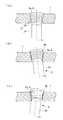
本実施形態に係る骨プレート1においては、幅広部4に設けた3個のネジ孔5aが、図4(a)〜(c)に示されるように、下孔に対して、該下孔の軸線C1に沿う方向、および、該軸線C1に対して傾斜する他の2つの軸線C2,C3に沿う方向に、タップDによってタップ加工を施すことにより形成された雌ネジ6を有している。これにより、ネジ孔5aにおける雌ネジ6は、先に形成された雌ネジ6のネジ山の一部を横切って新たな雌ネジ6が形成されたものとなっている。すなわち図4(b),(c)に示されるように、ハッチングで示した領域Eのネジ山の一部が削り取られている。In the
具体的には、図5(a)に示されるようにタップDにより、軸線C1に沿ってタップ加工を施した後に、図5(b),(c)に示されるように傾斜した軸線C2,C3に沿ってタップ加工を施すことにより、ネジ孔5a内に形成された雌ネジ6のネジ山を、符号Fの部分において削り取った雌ネジ6が形成されるようになっている。Specifically, the axis C tilted as shown in FIGS. 5B and 5C after being tapped along the axis C1 by the tap D as shown in FIG. 5A.2 , by tapping along C3 , a
本実施形態においては、タップ加工の軸線C2,C3を、ネジ孔5aの下孔の軸線C1を含み、骨プレート1の長手方向に沿う平面内において傾斜させている。タップ加工の軸線C2,C3の傾斜角度は、ネジ孔5aに形成される雌ネジ6のピッチにより異なるが、本実施形態においては、骨プレート1の長手方向に対向するネジ山が1山ずつずれてちょうど一致するようにタップを傾斜させて挿入する。これにより、ネジ孔5aに締結するスクリュ3は、図2および図6に示されるように、骨プレート1の長手方向に傾斜させて締結することができるようになっている。In the present embodiment, the axes C2 and C3 for tapping are inclined in a plane along the longitudinal direction of the
スクリュ3は、図2および図3に示されるように、細長い丸棒状に形成され、その外周面に、頸骨Aに形成された下孔(図示略)に締結される骨固定用の雄ネジ3aを備えるとともに、スクリュ3の頭部外周面には、骨プレート1のネジ孔5a,5bに締結されるテーパネジからなるプレート固定用の雄ネジ3bを備えている。 As shown in FIGS. 2 and 3, the
このように構成された本実施形態に係る骨プレート1および骨プレートシステム2の作用について、以下に説明する。
本実施形態に係る骨プレートシステム2を用いて変形膝関節症の高位頸骨骨切り術を行うには、頸骨Aの内側面から外側に向かって、頸骨Aの長手軸に対して傾斜する方向に切り込みを形成し、所定の器具を用いて切断面を開大する。そして、開大された切断面間に楔形状の補填材Bを挿入した状態で、頸骨Aの内側面に骨プレート1を宛い、切り込みを挟んで幅広部4に近い1つのネジ孔5bとそれ以外の4つのネジ孔5bとを配置し、該ネジ孔5b内に下孔を形成する。The operation of the
In order to perform high-level tibial osteotomy for knee osteoarthritis using the
この際に、幅広部4以外のネジ孔5bに対しては、各ネジ孔5bの軸線方向に沿って下孔を形成する。一方、幅広部4のネジ孔5aに対しては、頸骨Aの端面に略水平となるように下孔を形成する。そして、各ネジ孔5a,5bを貫通させて下孔にスクリュ3の骨固定用の雄ネジ3aを締結していき、最後に、ネジ孔5a,5bにスクリュ3の頭部に設けられたプレート固定用の雄ネジ3bを締結する。 At this time, for the screw holes 5b other than the
これにより、骨プレート1が頸骨Aの表面に沿って配置された状態に頸骨Aに固定される。この場合において、各ネジ孔5a,5bの雌ネジおよびスクリュ3のプレート固定用の雄ネジ3bはテーパネジにより構成されているので、締結の進行によって固定力が高まり、より確実に骨プレート1を頸骨Aの表面に固定することができる。 Thereby, the
また、本実施形態に係る骨プレート1および骨プレートシステム2によれば、幅広部4に設けられたネジ孔5aの雌ネジへのスクリュ3の雄ネジ3bの締結の角度は、図6(a)に示されるように、スクリュ3の軸線とネジ孔5aの軸線とが一致する角度の他、図6(b),(c)に示されるように、骨プレート1の長手方向に対向する雌ネジ6の部分への締結位置に対してネジ山1山分ずついずれかの方向にずらした角度の3通りの締結方法を選択することができる。 Further, according to the
変形膝関節症の高位頸骨骨切り術においては、頸骨Aの変形の度合いに応じて、頸骨Aに形成した切り込みの開大の程度が相違する他、頸骨Aの表面形状も患者毎に異なる。本実施形態に係る骨プレート1および骨プレートシステム2によれば、スクリュ3のネジ孔5aへの締結方法を適当に選択することにより、単一の形状の骨プレート1を全ての患者に適用しても、スクリュ3の固定方向を適正な方向に設定することができるという利点がある。 In the high tibial osteotomy for knee osteoarthritis, the degree of opening of the incision formed in the tibial A varies depending on the degree of deformation of the tibial A, and the surface shape of the tibial A varies from patient to patient. According to the
すなわち、単一の形状の骨プレート1を全ての患者に適用する場合には、スクリュ3の固定方向が単一であると幅広部4を固定するスクリュ3が頸骨Aの端面を貫通する方向に配置されてしまったり、スクリュ3が補填材Bを貫通する方向に配置されてしまったりする。これに対して、本実施形態によればそのような不都合はなく、骨プレート1を術場で変形等させるような面倒な作業を術者に強いることなく、幅広部4を固定するスクリュ3を頸骨Aの端面に略平行な方向に締結することができる。 That is, when the
また、本実施形態に係る骨プレート1および骨プレートシステム2によれば、幅広部4におけるネジ孔5aへのスクリュ3の締結方向を長手方向に傾斜させたとしても、予め異なる複数の方向にタップ加工が施されているので、締結によって雌ネジ6が削れるのを防止して、金属粉が発生する不都合の発生を防止することができる。 Further, according to the
また、骨プレート1のネジ孔5aの雌ネジ部6およびスクリュ3のプレート固定用の雄ネジ3bがテーパネジにより構成されているので、雄ネジ3bを雌ネジ部6に締結させる自由度が高く、ネジ孔5aの軸線に対してスクリュ3を傾斜させても両者をより確実に締結することができるという利点がある。 Further, since the
また、本実施形態においては、骨プレート1に幅広部4を設けて、該幅広部4に骨プレート1の長手方向に交差する方向に間隔をあけて3個のネジ孔5aを設けたので、これらのネジ孔5aに締結された3本のスクリュ3の張力によって、骨プレート1にかかるモーメントを受けることができ頸骨Aに捻りが加わっても、骨プレート1をしっかりと固定した状態に保持することができる。 Moreover, in this embodiment, since the
なお、本実施形態においては、骨プレート1を略T字形状に形成したが、これに限定されるものではなく、略L字形状に形成してもよい。また、幅広部4に、3個のネジ孔5aを設けたが、これに代えて、2個以上の任意の数のネジ孔5aを配置してもよい。また、骨プレート1は、図1に示す例では、頸骨Aに固定した際に幅広部4の反対側の端部が頸骨の外側に突出することを防止するために屈曲した形状を有しているが、この形状に限定されるものでもない。 In addition, in this embodiment, although the
また、幅広部4の3個のネジ孔5aを長手軸に直交する方向に間隔をあけて配置したが、これに代えて、図7に示されるように、長手方向に対して90°以下の角度で交差する方向に間隔をあけて配置してもよい。このようにすることで、幅広部4においても、ネジ孔5aの軸線を互いにねじれの位置に配置することができ、軸線が交差しないので、長いスクリュ3を用いても相互に干渉しないように締結することができる。 In addition, although the three
また、本実施形態においては、幅広部4に設けたネジ孔5aについてのみ、雌ネジ部6と逃げ部7とを周方向に交互に有する構造のものを採用したが、これに代えて、他のネジ孔5aについても同様の構造を採用してもよい。
また、本実施形態においては、対向する雌ネジ部6のネジ山を1山分ずらして締結する場合について説明したが、これに代えて、ネジのピッチを十分に小さく抑えることで、2山分以上ずらして締結することにしてもよい。In the present embodiment, only the
Moreover, in this embodiment, although the case where the thread of the
また、本実施形態においては、同一の下孔に対して行われるタップ加工の軸線C1〜C3の交点Pを図8(a)〜(c)に示されるように任意に設定することができる。すなわち、図8(a)に示されるように、スクリュ3の先端側において軸線C1〜C3を交差(交点P)させることにより、常に先端側の同一点Pを通過するようにスクリュ3を締結したり、骨プレート1のロッキング位置を微調整したりすることができる。また、図8(b)に示されるように、骨プレート1の板厚方向の中間位置に軸線C1〜C3の交点Pを配置することにより、骨プレート1のロッキング位置を移動させることなく、スクリュ3の角度を調節することができる。さらに、図8(c)に示されるように、骨プレート1を挟んで骨とは反対側に軸線C1〜C3の交点Pを配置することにより、スクリュ3の角度変更とロッキング位置の微調整とを同時に行うことができる。Moreover, in this embodiment, it is possible to arbitrarily set the intersection point P of the axes C1 to C3 of tapping performed on the same prepared hole as shown in FIGS. it can. That is, as shown in FIG. 8A, by making the axes C1 to C3 intersect (intersection point P) on the tip side of the
また、本実施形態においては、幅広部4に設けたネジ孔5aの雌ネジ部6およびこれに締結するスクリュ3のプレート固定用の雄ネジ3bをテーパネジにより構成したが、これに代えて、図9に示されるように、略球面状に湾曲した内面および外面に、球の略中心方向に向かって延びるネジ山を有する雌ネジ部6および雄ネジ3bを採用してもよい。このようにすることで、ネジ孔5aの軸線に対してスクリュ3の軸線を傾斜させても、雌ネジ部6とプレート固定用の雄ネジ3bとの接触範囲を大きく確保することができ、十分な固定力を得ることができるという利点がある。 Further, in the present embodiment, the
また、本実施形態においては、長手方向に沿う平面内においてタップ加工の軸線C2,C3を傾斜させてその平面内におけるスクリュ3の傾斜を可能としたが、タップ加工の軸線の傾斜方向を異ならせることで、他の方向へのスクリュ3の傾斜を可能とするネジ孔5aを構成することにしてもよい。また、このようにすることで、2方向のみならず3方向以上のスクリュの締結角度の選択が可能となる。In the present embodiment, the axis C2 and C3 for tapping are inclined in a plane along the longitudinal direction so that the
A 頸骨(骨)
1 骨プレート
2 骨プレートシステム
3 スクリュ
3b 雄ネジ(雄ネジ部)
5a,5b ネジ孔
6 雌ネジA Tibial bone
1
5a,
Claims (8)
Translated fromJapanese長手方向に間隔をあけて配置された板厚方向に貫通する複数のネジ孔を備え、
長手方向の端部に配置される少なくとも1つのネジ孔が、下孔の軸線と該軸線に対して傾斜した1以上の軸線に沿ってタップ加工を施すことにより構成された雌ネジを有する骨プレート。Formed in the shape of a strip placed along the bone surface,
Provided with a plurality of screw holes penetrating in the thickness direction arranged at intervals in the longitudinal direction,
A bone plate having at least one screw hole disposed at an end in a longitudinal direction and having an internal thread formed by tapping along an axis of a pilot hole and one or more axes inclined with respect to the axis .
該骨プレートを骨に固定する複数のスクリュとを備え、
該スクリュが、その頭部に、前記骨プレートに設けられたネジ孔の前記雌ネジに締結される雄ネジを有する骨プレートシステム。The bone plate according to any one of claims 1 to 5,
A plurality of screws for fixing the bone plate to the bone;
The bone plate system in which the screw has a male screw fastened to the female screw of a screw hole provided in the bone plate at the head.
該骨プレートを骨に固定する複数のスクリュとを備え、
該スクリュが、その頭部外面に、前記骨プレートに設けられたネジ孔のテーパ雌ネジに締結されるテーパ雄ネジを有する骨プレートシステム。A bone plate according to claim 4;
A plurality of screws for fixing the bone plate to the bone;
A bone plate system in which the screw has a taper male screw fastened to a taper female screw of a screw hole provided in the bone plate on an outer surface of the head.
該骨プレートを骨に固定する複数のスクリュとを備え、
該スクリュが、その球面状の頭部外面に、前記骨プレートに設けられた球面状のネジ孔内面の雌ネジに締結される雄ネジを有する骨プレートシステム。A bone plate according to claim 5;
A plurality of screws for fixing the bone plate to the bone;
A bone plate system in which the screw has a male screw fastened to a female screw on an inner surface of a spherical screw hole provided in the bone plate on the outer surface of the spherical head.
Priority Applications (1)
| Application Number | Priority Date | Filing Date | Title |
|---|---|---|---|
| JP2009086965AJP2010233915A (en) | 2009-03-31 | 2009-03-31 | Bone plate and bone plate system |
Applications Claiming Priority (1)
| Application Number | Priority Date | Filing Date | Title |
|---|---|---|---|
| JP2009086965AJP2010233915A (en) | 2009-03-31 | 2009-03-31 | Bone plate and bone plate system |
Publications (1)
| Publication Number | Publication Date |
|---|---|
| JP2010233915Atrue JP2010233915A (en) | 2010-10-21 |
Family
ID=43088837
Family Applications (1)
| Application Number | Title | Priority Date | Filing Date |
|---|---|---|---|
| JP2009086965APendingJP2010233915A (en) | 2009-03-31 | 2009-03-31 | Bone plate and bone plate system |
Country Status (1)
| Country | Link |
|---|---|
| JP (1) | JP2010233915A (en) |
Cited By (2)
| Publication number | Priority date | Publication date | Assignee | Title |
|---|---|---|---|---|
| JP2015077300A (en)* | 2013-10-17 | 2015-04-23 | ミズホ株式会社 | Bone fixation device |
| USD779065S1 (en) | 2014-10-08 | 2017-02-14 | Nuvasive, Inc. | Anterior cervical bone plate |
Citations (5)
| Publication number | Priority date | Publication date | Assignee | Title |
|---|---|---|---|---|
| US20040073218A1 (en)* | 2002-10-15 | 2004-04-15 | The University Of North Carolina At Chapel Hill | Multi-angular fastening apparatus and method for surgical bone screw/plate systems |
| JP2006521149A (en)* | 2003-03-26 | 2006-09-21 | スイス オーソペディック ソリューションズ ソシエテ アノニム | Osteosynthesis fixation plate |
| JP2007500069A (en)* | 2003-05-30 | 2007-01-11 | シンセス ゲーエムベーハー | Bone plate |
| JP2007506450A (en)* | 2003-08-26 | 2007-03-22 | ジンテーズ ゲゼルシャフト ミト ベシュレンクテル ハフツング | Bone plate |
| JP2007515990A (en)* | 2003-06-20 | 2007-06-21 | アキュームド・エルエルシー | Bone plate with openings that are threaded during surgery |
- 2009
- 2009-03-31JPJP2009086965Apatent/JP2010233915A/enactivePending
Patent Citations (5)
| Publication number | Priority date | Publication date | Assignee | Title |
|---|---|---|---|---|
| US20040073218A1 (en)* | 2002-10-15 | 2004-04-15 | The University Of North Carolina At Chapel Hill | Multi-angular fastening apparatus and method for surgical bone screw/plate systems |
| JP2006521149A (en)* | 2003-03-26 | 2006-09-21 | スイス オーソペディック ソリューションズ ソシエテ アノニム | Osteosynthesis fixation plate |
| JP2007500069A (en)* | 2003-05-30 | 2007-01-11 | シンセス ゲーエムベーハー | Bone plate |
| JP2007515990A (en)* | 2003-06-20 | 2007-06-21 | アキュームド・エルエルシー | Bone plate with openings that are threaded during surgery |
| JP2007506450A (en)* | 2003-08-26 | 2007-03-22 | ジンテーズ ゲゼルシャフト ミト ベシュレンクテル ハフツング | Bone plate |
Cited By (3)
| Publication number | Priority date | Publication date | Assignee | Title |
|---|---|---|---|---|
| JP2015077300A (en)* | 2013-10-17 | 2015-04-23 | ミズホ株式会社 | Bone fixation device |
| USD779065S1 (en) | 2014-10-08 | 2017-02-14 | Nuvasive, Inc. | Anterior cervical bone plate |
| USD798455S1 (en) | 2014-10-08 | 2017-09-26 | Nuvasive, Inc. | Anterior cervical bone plate |
Similar Documents
| Publication | Publication Date | Title |
|---|---|---|
| WO2012042592A1 (en) | Bone plate and bone plate system | |
| US8323321B2 (en) | Implant and bone screw having interlocking cams | |
| EP2559394B1 (en) | Highly-versatile variable-angle bone plate system | |
| JP6296466B2 (en) | Bone plate and bone plate system | |
| JP5014549B2 (en) | Palm-side fixing device | |
| JP6082501B1 (en) | Bone plate and bone plate system | |
| EP3019101B1 (en) | Fixation assembly with a flexible elongated member for securing parts of a sternum | |
| RU2659017C2 (en) | Screw with universal length and cutting tools | |
| JP5777047B2 (en) | Bone plate system | |
| JP5505767B2 (en) | Bone plate and bone plate system | |
| EP3178423B1 (en) | Bone plate with polyaxial locking mechanism | |
| KR101670273B1 (en) | Locking fixing system for orthopedic implants | |
| JP2010233915A (en) | Bone plate and bone plate system | |
| AU2021106958A4 (en) | A bone fixation system and a plate therefor | |
| JP6852201B2 (en) | Lockable web plate | |
| KR101849380B1 (en) | Coordination locking fixing system for orthopedic implant | |
| US11083507B2 (en) | Screw with a variable locking angle and a corresponding locking system | |
| JP6616767B2 (en) | Fracture fixator | |
| JP5419426B2 (en) | Osteosynthesis device | |
| US20150039038A1 (en) | Orthopedic Screw Fastener System Including Locking and Non-Locking Screws | |
| JP6199609B2 (en) | Bone surgery guide instrument and bone surgery instrument set | |
| JP2014147553A (en) | Fracture treatment plate |
Legal Events
| Date | Code | Title | Description |
|---|---|---|---|
| A621 | Written request for application examination | Free format text:JAPANESE INTERMEDIATE CODE: A621 Effective date:20120228 | |
| A977 | Report on retrieval | Free format text:JAPANESE INTERMEDIATE CODE: A971007 Effective date:20130719 | |
| A131 | Notification of reasons for refusal | Free format text:JAPANESE INTERMEDIATE CODE: A131 Effective date:20130730 | |
| A521 | Written amendment | Free format text:JAPANESE INTERMEDIATE CODE: A523 Effective date:20130927 | |
| A131 | Notification of reasons for refusal | Free format text:JAPANESE INTERMEDIATE CODE: A131 Effective date:20140128 | |
| A131 | Notification of reasons for refusal | Free format text:JAPANESE INTERMEDIATE CODE: A131 Effective date:20140729 | |
| A02 | Decision of refusal | Free format text:JAPANESE INTERMEDIATE CODE: A02 Effective date:20150127 |