JP2010229642A - Rail buckling prevention safety device - Google Patents
Rail buckling prevention safety deviceDownload PDFInfo
- Publication number
- JP2010229642A JP2010229642AJP2009075664AJP2009075664AJP2010229642AJP 2010229642 AJP2010229642 AJP 2010229642AJP 2009075664 AJP2009075664 AJP 2009075664AJP 2009075664 AJP2009075664 AJP 2009075664AJP 2010229642 AJP2010229642 AJP 2010229642A
- Authority
- JP
- Japan
- Prior art keywords
- wall
- side end
- buckling prevention
- fixing member
- sleeper
- Prior art date
- Legal status (The legal status is an assumption and is not a legal conclusion. Google has not performed a legal analysis and makes no representation as to the accuracy of the status listed.)
- Granted
Links
Images


Classifications
- E—FIXED CONSTRUCTIONS
- E01—CONSTRUCTION OF ROADS, RAILWAYS, OR BRIDGES
- E01B—PERMANENT WAY; PERMANENT-WAY TOOLS; MACHINES FOR MAKING RAILWAYS OF ALL KINDS
- E01B13/00—Arrangements preventing shifting of the track
- E01B13/02—Rail anchors
Landscapes
- Engineering & Computer Science (AREA)
- Mechanical Engineering (AREA)
- Architecture (AREA)
- Civil Engineering (AREA)
- Structural Engineering (AREA)
- Machines For Laying And Maintaining Railways (AREA)
- Railway Tracks (AREA)
- Train Traffic Observation, Control, And Security (AREA)
Abstract
Translated fromJapaneseDescription
Translated fromJapanese本発明は、鉄道におけるレールに座屈が発生することを防止するための保安装置に関する。 The present invention relates to a safety device for preventing buckling of a rail in a railway.
鉄道における線路は直線状に設けることが好ましいとされているが、曲線状の線路で滑らかに接続されていることも多い。このような曲線状の線路を走行する列車には遠心力が働いて、車両を曲線の外方に向かって倒そうとする力となって作用するほか、走行する車両の荷重による振動も加わるので、軌道の変形や位置ずれなどが発生することは避けられない。そこで線路を確実に支持し固定するためのまくらぎや道床などの構造にも、強度や経済性の観点からの改良が進められ、まくらぎ等も鋼線強化コンクリート製のものが、汎用されるに至っている。 The railroad tracks are preferably provided in a straight line, but are often smoothly connected by a curved track. Centrifugal force acts on a train traveling on such a curved track, acting as a force that tries to tilt the vehicle toward the outside of the curve, and vibration due to the load of the traveling vehicle is also added. It is inevitable that the trajectory is deformed or displaced. Therefore, the structure of sleepers and roadbeds to securely support and fix the track has been improved from the viewpoint of strength and economy, and sleepers made of steel wire reinforced concrete are widely used. Has reached.
しかし、線路の保守作業に関しては機械化などが進められているものの、人力による保守作業の負荷は大幅には改善されておらず、特に夏期には軌道温度の上昇による線路の膨張で座屈が発生すると、信号トラブルや脱線事故などに繋がる恐れもあって、保線作業員への負荷が増大する傾向にあるので、保線作業の合理化が強く求められ、更にこれに加えて事故発生の予防のための設備の改良にも、機能や耐久性と共に経済性も重視されるようになっている。 However, although the mechanization of track maintenance work has been promoted, the load of maintenance work by human power has not been improved significantly, and buckling occurs due to the expansion of the track due to the rise of track temperature, especially in summer. Then, it may lead to signal troubles and derailment accidents, and the load on track maintenance workers tends to increase, so rationalization of track maintenance work is strongly required, and in addition to this, prevention of accident occurrence Improvements in equipment are also focused on economics as well as function and durability.
そこで本発明は、鉄道における線路の変形や座屈の発生を防止すると同時に、設備取付や補修の作業効率を大幅に改善して、安全で保守が容易な線路構造を迅速に構築することができ、且つ保線作業の負荷を軽くして、保守の作業労力と経費との大幅な節約を図ることができる、レール座屈防止用保安装置を提供することを目的としたものである。 Therefore, the present invention can prevent the occurrence of rail deformation and buckling in a railway, and at the same time, can greatly improve the work efficiency of equipment installation and repair, and can quickly build a safe and easy-to-maintain track structure. It is another object of the present invention to provide a rail buckling prevention safety device that can reduce the load of the track maintenance work and can greatly reduce the maintenance work effort and cost.
上記の目的を達成できる本発明のレール座屈防止用保安装置は、まくらぎの側端部底面と側端部下半端面と側端部下半左面と側端部下半右面とをそれぞれ支持できる底壁と下前壁と下左壁と下右壁とに加えて該下左壁の外面と該下右壁の外面とに鏡面対称状に突設された左右1対の下結合片を有し、該側端部下半端面と該下前壁の内面との間に板状の杭体を挿通できる下半空隙を設けた側端部下半固定部材1と、まくらぎの側端部上面と側端部上半端面と側端部上半左面と側端部上半右面とをそれぞれ支持できる上壁と上前壁と上左壁と上右壁とに加えて該上左壁の外面と該上右壁の外面とに鏡面対称状に突設された左右1対の上結合片を有し、該側端部上半端面と該上前壁の内面との間に板状の杭体を挿通できる上半空隙を設けた側端部上半固定部材2と、左方の該上結合片と左方の該下結合片とを結合する左緊締具3と、右方の該上結合片と右方の該下結合片とを結合する右緊締具4と、前記上半空隙及び前記下半空隙に上方から挿通できる座屈防止杭板5とを備えてなることを、要旨とする。 The rail buckling prevention safety device of the present invention that can achieve the above object comprises a bottom wall capable of supporting a side end bottom surface, a side end lower half end surface, a side end lower half left surface, and a side end lower half right surface of the sleeper, respectively. In addition to the lower front wall, the lower left wall, and the lower right wall, the outer left surface and the outer surface of the lower right wall have a pair of left and right lower coupling pieces projecting in mirror symmetry, Side end lower
本発明のレール座屈防止用保安装置において、側端部下半固定部材1、側端部上半固定部材2、及び座屈防止杭板5の各部材の少なくとも1以上は鉄合金鋳造品からなるものが好ましく用いられ、また、側端部下半固定部材1と側端部上半固定部材2とを、それぞれに突設された左右1対の下結合片と左右1対の上結合片とを介して結合する左緊締具3と右緊締具4としては、鋼製のボルトとナットを用いることが好ましい。 In the rail buckling prevention safety device of the present invention, at least one of each of the side end lower
本発明のレール座屈防止用保安装置は、まくらぎの側端部、特に好ましくは左右の両側端部に、側端部下半固定部材1と側端部上半固定部材2とを、前緊締具3と後緊締具4を用いて上下から締め付けるように装着した後に、側端部下半固定部材1及び側端部上半固定部材2と、まくらぎの側端部との間に設けた空隙に、座屈防止杭板5を上方から挿通し、更に砕石等を用いて築造された従来型の道床に、座屈防止杭体5を打ち込むか又は圧入することで、道床に対するまくらぎ位置、従ってレール位置が変ることを防止できる。また、座屈防止杭板5の道床への圧入深さを、まくらぎ位置と同様に固定したい場合には、座屈防止杭板5を側端部上半固定部材2にボルト締めにより結合すればよい。 The rail buckling prevention safety device of the present invention has a side end
本発明のレール座屈防止用保安装置は、鉄道の線路を構成するレールを載置して、道床上の所定の位置に設置するためのまくらぎが、レール上を走行する車両又はレール自体が発生する種々の外力によって、移動を起こして線路形状を歪ませる危険を防止するための装置である。そして本発明では、上記のような線路内で発生する歪応力を、まくらぎ自体で一旦受けて、レールの弾性変形か道床の塑性変形に変換することで、解消させようとするものである。 In the rail buckling prevention safety device of the present invention, a sleeper for placing a rail constituting a railroad track and installing it at a predetermined position on a roadbed is a vehicle traveling on the rail or the rail itself. This is a device for preventing the danger of causing the movement and distorting the line shape by various external forces generated. In the present invention, the strain stress generated in the track as described above is temporarily received by the sleeper itself and converted into elastic deformation of the rail or plastic deformation of the road bed.
そこで本発明のレール座屈防止用保安装置Aを、以下に図面に基づいて詳細に説明する。
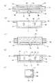
図1は、本発明のレール座屈防止用保安装置を組み立てた状態の例を示しているが、ここでのSは、例えば予備緊張鋼線などで強化したコンクリート製まくらぎ(仮想状態)を示すものとし、1は、まくらぎSの一方の側端部の下半部分S1の端面と左側面と右側面と底面部分とを、共に覆うことができる形状を備えた、例えば鋳鋼製などの側端部下半固定部材である。そして2は、同じまくらぎSの同じ側端部の上半部分S2の端面と左面と右面と上面部分とを、共に覆うことができる形状を備えた、例えば鋳鋼製などの側端部上半固定部材である。この図面からはまくらぎSの一方の側端部とはどの部分を指すのか明確ではないが、符号1で指定した部材で覆われている部分が、まくらぎSの一方の側端部の下半部分S1であり、符号2で指定した部材で覆われている部分が、同じまくらぎSの側端部の上半部分S2であって、符号1の部材と符号2の部材で覆われている部分を合わせて側端部S0とする。Therefore, the rail buckling prevention safety device A of the present invention will be described in detail with reference to the drawings.
FIG. 1 shows an example of the assembled state of the rail buckling prevention safety device according to the present invention, where S is a concrete sleeper (virtual state) reinforced with, for example, a pre-tensioned steel wire. As shown, 1 is provided with a shape that can cover the end surface, the left side surface, the right side surface, and the bottom surface portion of the lower half portion S1 of one side end of the sleeper S, such as cast steel. It is a side end lower half fixing member. 2 is a side end upper half made of cast steel, for example, having a shape capable of covering the end face, the left side, the right side and the upper side of the upper half S2 of the same side end of the same sleeper S together. It is a fixing member. Although it is not clear from this drawing which part is the one side edge of the sleeper S, the part covered by the member designated by
上記の側端部下半固定部材1の構造を、図2に基づいて詳細に説明するが、図2における(a)は上面図、(b)は正面図、(c)は底面図、(d)は背面図、(e)は(d)の切断位置における立断面図である。
これらの図面において、1aは側端部下半固定部材1の底壁であるが、その底壁の上面には鋭角な稜線を有する凸条が設けてあり、まくらぎSの側端部S0の底面が滑ることなく載荷できるようになっている。そして、上記の底壁1aを囲む位置には、まくらぎSの側端部S1の端面前に空隙を残すように端面を覆う下前壁1bを設けると共に、下前壁1bの左端部分と、中央位置の上端部分及び下端部分と、右端部分とに、まくらぎSの側端部S1の端面を支える空隙維持突起1e、1f、1g、1hを設けたほか、まくらぎSの側端部S1の端面と下前壁1bとの空隙を観察できる1対の窓孔1jが設けてあり、更にまくらぎSの側端部の下半部分S1の左側面と右側面とを、それぞれ適切な位置に導くための下左壁1cと下右壁1dとが設けてあるほか、1対の杭板挿通孔1k、1kが形成されている。The structure of the side end lower
In these drawings,
更に、まくらぎSの側端部の上半部分S2を覆う側端部上半固定部材2の構造を、図3に基づいて詳細に説明する。図3における(a)は上面図、(b)は正面図、(c)は底面図、
(d)は背面図、(e)は(d)の切断位置における立断面図である。
これらの図面において、2aはまくらぎSの側端部の上面を覆う側端部上半固定部材2の上壁であり、その上壁2aの下面には、側端部下半固定部材1の底壁1aと同様に、鋭角な稜線を有する凸条が設けてあるので、まくらぎSの側端部の上面に載置された上壁2aは滑動する恐れがない。そして上記の上壁2aを囲む位置に、まくらぎSの側端部S2の端面前に空隙を残すように端面を覆う上前壁2bを設けると共に、上前壁2bの中央位置の上端部分及び下端部分に、まくらぎSの側端部S2の端面を支える空隙維持突起2e、2f、を設けたほか、まくらぎSの側端部S2の端面と上前壁2bとの空隙を観察できる1対の窓孔2g、2gが設けてあり、更にまくらぎSの側端部の上半部分S2の左側面と右側面とを、それぞれ適切な位置に導くための上左壁2cと上右壁2dとが設けてあるほか、1対の杭板挿通孔2h、2hが形成されている。Furthermore, the structure of the side end upper
(d) is a rear view, (e) is an elevational sectional view at the cutting position of (d).
In these drawings, 2a is an upper wall of the side end upper
そして、このような側端部下半固定部材1の上縁に近い左右の側面には、左ボルト挿通孔を設けた左下結合片1mと、右ボルト挿通孔を設けた右下結合片1nとが、左右1対として鏡面対称状に水平に突設されている。また、側端部上半固定部材2の下縁に近い左右の側面には、左ボルト挿通孔を設けた左上結合片2mと、右ボルト挿通孔を設けた右上結合片2nとが、左右1対として鏡面対称状に水平に突設されている。そして、これらの側端部下半固定部材1と側端部上半固定部材2とが、同じまくらぎSの同じ側端部の下半部分と上半部分とに上下に取り付けられると、左下結合片1mの上方に左上結合片2mが位置すると同時に、右下結合片1nの上方に右上結合片2nが位置することになるので、左ボルト挿通孔と左ボルト挿通孔とに、ボルトとナットからなる左緊締具3を挿通して、左下結合片1mと左上結合片2mを緊密に結合することができ、また右ボルト挿通孔と右ボルト挿通孔とに、ボルトとナットからなる右緊締具4を挿通して、右下結合片1nと右上結合片2nを緊密に結合することもできる。従ってまくらぎSの同じ側端部は、側端部上半固定部材2と側端部下半固定部材1との間に挟まれ、上下から確実に締め付けられる結果、鋼材などで製造された左右何れかの緊締具3又は4が破壊しない限り、装置が分解する恐れはない。 Then, on the left and right side surfaces close to the upper edge of such a side end lower
このようにして、まくらぎSに、側端部下半固定部材1と、側端部上半固定部材2と、左緊締具3及び右緊締具4とを組み付けて形成された中間組立装置は、上端位置に1対の杭板挿通孔2h、2hが開口していて、これにまくらぎSの側端部S0の端面と、側端部上半固定部材2の上前壁2bの内面と側端部下半固定部材1の下前壁1bの内面と、の間に残された縦の空隙が続き、その空隙の最後は1対の杭板挿通孔1k、1kの開口で終わっている。 Thus, the intermediate assembly apparatus formed by assembling the side end lower
そこで上記の中間組立装置内に残された縦の空隙には、図4及び図5に示すような構造の、例えば振動減衰能を有するFCD450等の鋳鉄材製などの座屈防止杭板5を、装置上端の杭板挿通孔2hから挿入して、下端の杭板挿通孔1kから突出させるが、座屈防止杭板5の挿入過程は、上前壁2bや下前壁1bに設けてある窓孔2gや窓孔1gを介して観察でき、更には、これらの窓孔2gや窓孔1gから差し込んだ固定ボルト6を、座屈防止杭板5の雌ネジ孔5bに螺着して、座屈防止杭板5を上前壁2bや下前壁1bに結合すれば、完成後の本発明のレール座屈防止用保安装置での座屈防止杭板5取付位置が、変動することを抑制できる。 Therefore, in the vertical gap left in the intermediate assembly apparatus, a buckling
ところで本発明のレール座屈防止用保安装置Aにおいて、上記のように座屈防止杭板5の取付位置を固定すると、道床などの土質の違いに対応できない場合には、座屈防止杭板5の形状や寸法などの変更が容易でなくなる恐れがある。そこで本発明のレール座屈防止用保安装置に装着される座屈防止杭板5は、固定を解除できるよう構成されているが、選択可能な交換部品として、機能や性能が異なる複数種類の座屈防止杭板を準備することは当然に必要である。そこで機能の異なる座屈防止杭板7として、図6に示した部品の使用について、以下に説明する。 By the way, in the rail buckling prevention safety device A of the present invention, when the mounting position of the buckling
図6に示した座屈防止杭板7は、道床への打ち込みを容易にするために、板幅を先に向かって細くしてあるほか、戻り止め用突起7cが連設されており、また座屈防止杭板5に設けてある雌ネジ孔5bに代えて、摺動スリット7bを設けてなるものである。このような座屈防止杭板7を装置上端の杭板挿通孔2hから挿入し、摺動スリット7bに沿って移動可能としたガイドピンを、窓孔2gや窓孔1gなどに取り付けてなる本発明のレール座屈防止用保安装置Bは、杭板挿通孔1kから座屈防止杭板7の先端が突出して道床内に入っている形態をとるので、まくらぎSの振動が道床と座屈防止杭板7の間に位相差のある振動を起こし、結果として座屈防止杭板7が摺動スリット7bの長さの範囲内で更に深く、沈み込むことができる。 The buckling
また、本発明のレール座屈防止用保安装置については、これまで、まくらぎSの一方の側端部に本発明のレール座屈防止用保安装置を設けることの説明をしてきた。しかしながら、この本発明の装置は、本質的に左右対称な構造を有していて、これまた左右対称な構造を有するまくらぎSの、他方の側端部に本発明のレール座屈防止用保安装置を設けることに、何等の不自然さもない。従って1個のまくらぎSの双方の側端部に、それぞれ本発明のレール座屈防止用保安装置を設けることは、効果が倍となることを意味し、鉄道の線路が2本のレールで構成されていることから見ても、合理的と言える。 Moreover, about the rail buckling prevention safety device of the present invention, it has been described so far that the rail buckling prevention security device of the present invention is provided at one side end of the sleeper S. However, this device of the present invention has an essentially symmetrical structure, and the rail buckling prevention security of the present invention is provided at the other side end of the sleeper S having the symmetrical structure. There is no unnaturalness in providing the device. Therefore, providing the rail buckling prevention safety device of the present invention at both side ends of one sleeper S means that the effect is doubled, and the railroad track is composed of two rails. It can be said that it is reasonable even if it is composed.
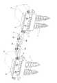
そうであれば、鉄道の線路には多数のまくらぎが道床上に所定の間隔で配置されていることを考えれば、道床が築造された地盤における土質の安定性を補うために、隣接するまくらぎに本発明のレール座屈防止用保安装置を、所望の数だけ次々に設けることが有効であると言え、こうした本発明の施工形態の例を、図8に示す。此の例では、隣接したまくらぎS、Sの一方側端部のそれぞれに、例えばレール座屈防止用保安装置Bを設けると共に、一方の保安装置Bの左緊締具3の上端部と、その左隣の保安装置Bの右緊締具4の上端部とを、端子部材8aと延長部材8bとをボルトナット結合して成る連結装置8で、連結するなどの手段を用いて、まくらぎS、Sの間隔を所望の値となるよう固定したものである。 If this is the case, considering that a large number of sleepers are arranged on the roadbed at predetermined intervals on the railroad tracks, adjacent pillows are used to supplement the soil stability in the ground where the roadbed is built. It can be said that it is effective to provide a desired number of rail buckling prevention safety devices according to the present invention one after another. FIG. 8 shows an example of the construction mode according to the present invention. In this example, for example, a rail buckling prevention safety device B is provided at each of the one end portions of the adjacent sleepers S, S, and the upper end portion of the left
次に、既存の鉄道の線路に本発明のレール座屈防止用保安装置を設置する場合について説明する。
線路における設置を望む位置にあるレールとまくらぎとを外した後、前記の中間組立装置を道床上に配設して、通常の線路取替作業の手順に準じてレールの取付作業を進め、レールの取付位置修正が終わった時点で、座屈防止杭板を中間組立装置の杭板挿通孔2hに挿入し、座屈防止杭板の頭5aを打撃するか又は押圧するなどの手段により、座屈防止杭板を必要な深さまで道床内に沈下させて、本発明のレール座屈防止用保安装置を完成させる。なお、このような座屈防止杭板の取付作業の間には、所望に応じて固定ボルト6などの取り付け又は締め付け等の作業を進めることが、望ましい。Next, the case where the rail buckling prevention safety device of the present invention is installed on an existing railway track will be described.
After removing the rails and sleepers at the desired location on the track, arrange the intermediate assembly device on the roadbed, and proceed with the rail mounting work according to the normal track replacement procedure, When the rail mounting position correction is completed, the buckling prevention pile plate is inserted into the pile
本発明のレール座屈防止用保安装置は、本来の目的であった、気温の高い季節においてレールの温度が特に上昇し、レールが伸長して座屈をおこす事故の防止は、実用試験によって、略満足できる成果が得られることが判ったが、本装置の構造並びに作用機構から考えて、単にレールの座屈防止と言うに止まらず、地上に敷設された鉄道施設に対する保安装置として、広く応用することが期待される。 The rail buckling prevention safety device of the present invention was originally intended to prevent an accident in which the rail temperature particularly rises during the high temperature season and the rail extends to cause buckling. Although it has been found that satisfactory results can be obtained, considering the structure and operation mechanism of this device, it can be applied widely as a safety device for railway facilities laid on the ground, not just to prevent rail buckling. Is expected to do.
A、B レール座屈防止用保安装置
S まくらぎ
S0 まくらぎSの側端部
S1 側端部の下半部分
S2 側端部の上半部分
1 側端部下半固定部材
1a 底壁
1b 下前壁
1c 下左壁
1d 下右壁
1e、1f、1g、1h 空隙維持突起
1j 窓孔
1k 杭板挿通孔
1m 左下結合片
1n 右下結合片
2 側端部上半固定部材
2a 上壁
2b 上前壁
2c 上左壁
2d 上右壁
2e、2f 空隙維持突起
2g 窓孔
2h 杭板挿通孔
2m 左上結合片
2n 右上結合片
3 左緊締具
4 右緊締具
5 座屈防止杭板
5a 頭
5b 雌ネジ孔
6 固定ボルト
7 座屈防止杭板
7a 頭
7b 摺動スリット
7c 戻り止め用突起
8 連結装置
8a 端子部材
8b 延長部材A, B Rail buckling prevention safety device S Sleeper S0 Sleeper S Side end S1 Lower end lower half S2
Claims (2)
Translated fromJapanesePriority Applications (3)
| Application Number | Priority Date | Filing Date | Title |
|---|---|---|---|
| JP2009075664AJP4512661B1 (en) | 2009-03-26 | 2009-03-26 | Rail buckling prevention safety device |
| KR1020090103463AKR20100108180A (en) | 2009-03-26 | 2009-10-29 | Safety device for preventing rails from buckling |
| TW099108902ATWI344499B (en) | 2009-03-26 | 2010-03-25 | Safety device for preventing rails from buckling |
Applications Claiming Priority (1)
| Application Number | Priority Date | Filing Date | Title |
|---|---|---|---|
| JP2009075664AJP4512661B1 (en) | 2009-03-26 | 2009-03-26 | Rail buckling prevention safety device |
Publications (2)
| Publication Number | Publication Date |
|---|---|
| JP4512661B1 JP4512661B1 (en) | 2010-07-28 |
| JP2010229642Atrue JP2010229642A (en) | 2010-10-14 |
Family
ID=42582576
Family Applications (1)
| Application Number | Title | Priority Date | Filing Date |
|---|---|---|---|
| JP2009075664AActiveJP4512661B1 (en) | 2009-03-26 | 2009-03-26 | Rail buckling prevention safety device |
Country Status (3)
| Country | Link |
|---|---|
| JP (1) | JP4512661B1 (en) |
| KR (1) | KR20100108180A (en) |
| TW (1) | TWI344499B (en) |
Cited By (11)
| Publication number | Priority date | Publication date | Assignee | Title |
|---|---|---|---|---|
| JP2012041791A (en)* | 2010-08-23 | 2012-03-01 | Hosen Kiki Seibi Kk | Article fixing implement for concrete sleeper |
| WO2017006701A1 (en) | 2015-07-08 | 2017-01-12 | 林総事株式会社 | Safety device for preventing rail buckling and movement |
| JP2017223041A (en)* | 2016-06-15 | 2017-12-21 | 西日本旅客鉄道株式会社 | Rail buckling prevention device and installation method thereof |
| US10378459B2 (en)* | 2017-03-23 | 2019-08-13 | Ford Global Technologies, Llc | Method and system for engine control |
| US10582187B2 (en) | 2015-02-20 | 2020-03-03 | Tetra Tech, Inc. | 3D track assessment method |
| US10625760B2 (en) | 2018-06-01 | 2020-04-21 | Tetra Tech, Inc. | Apparatus and method for calculating wooden crosstie plate cut measurements and rail seat abrasion measurements based on rail head height |
| US10728988B2 (en) | 2015-01-19 | 2020-07-28 | Tetra Tech, Inc. | Light emission power control apparatus and method |
| US10730538B2 (en) | 2018-06-01 | 2020-08-04 | Tetra Tech, Inc. | Apparatus and method for calculating plate cut and rail seat abrasion based on measurements only of rail head elevation and crosstie surface elevation |
| US10807623B2 (en) | 2018-06-01 | 2020-10-20 | Tetra Tech, Inc. | Apparatus and method for gathering data from sensors oriented at an oblique angle relative to a railway track |
| US10908291B2 (en) | 2019-05-16 | 2021-02-02 | Tetra Tech, Inc. | System and method for generating and interpreting point clouds of a rail corridor along a survey path |
| US11377130B2 (en) | 2018-06-01 | 2022-07-05 | Tetra Tech, Inc. | Autonomous track assessment system |
Families Citing this family (3)
| Publication number | Priority date | Publication date | Assignee | Title |
|---|---|---|---|---|
| KR101634127B1 (en)* | 2015-08-13 | 2016-06-29 | 한국철도기술연구원 | Apparatus for restraining horizontal-vertical movement of wide sleeper and slab panel, and construction method for the same |
| JP6317850B1 (en)* | 2017-11-27 | 2018-04-25 | 林総事株式会社 | Sleeper with buckling prevention function and movement prevention function |
| CN117648835B (en)* | 2024-01-30 | 2024-04-16 | 安徽省交通控股集团有限公司 | BRB design parameter optimization method suitable for highway pile plate type structure |
Citations (4)
| Publication number | Priority date | Publication date | Assignee | Title |
|---|---|---|---|---|
| JPS4973105U (en)* | 1972-10-12 | 1974-06-25 | ||
| JPH0341957U (en)* | 1989-09-01 | 1991-04-22 | ||
| JPH10227001A (en)* | 1997-02-14 | 1998-08-25 | East Japan Railway Co | Rail buckling prevention device |
| JP2002212901A (en)* | 2001-01-16 | 2002-07-31 | Hayashi Soji Kk | Sleeper coupling device and railway branching device |
- 2009
- 2009-03-26JPJP2009075664Apatent/JP4512661B1/enactiveActive
- 2009-10-29KRKR1020090103463Apatent/KR20100108180A/ennot_activeCeased
- 2010
- 2010-03-25TWTW099108902Apatent/TWI344499B/ennot_activeIP Right Cessation
Patent Citations (4)
| Publication number | Priority date | Publication date | Assignee | Title |
|---|---|---|---|---|
| JPS4973105U (en)* | 1972-10-12 | 1974-06-25 | ||
| JPH0341957U (en)* | 1989-09-01 | 1991-04-22 | ||
| JPH10227001A (en)* | 1997-02-14 | 1998-08-25 | East Japan Railway Co | Rail buckling prevention device |
| JP2002212901A (en)* | 2001-01-16 | 2002-07-31 | Hayashi Soji Kk | Sleeper coupling device and railway branching device |
Cited By (25)
| Publication number | Priority date | Publication date | Assignee | Title |
|---|---|---|---|---|
| JP2012041791A (en)* | 2010-08-23 | 2012-03-01 | Hosen Kiki Seibi Kk | Article fixing implement for concrete sleeper |
| US10728988B2 (en) | 2015-01-19 | 2020-07-28 | Tetra Tech, Inc. | Light emission power control apparatus and method |
| US11259007B2 (en) | 2015-02-20 | 2022-02-22 | Tetra Tech, Inc. | 3D track assessment method |
| US10616557B2 (en) | 2015-02-20 | 2020-04-07 | Tetra Tech, Inc. | 3D track assessment method |
| US11399172B2 (en) | 2015-02-20 | 2022-07-26 | Tetra Tech, Inc. | 3D track assessment apparatus and method |
| US11196981B2 (en) | 2015-02-20 | 2021-12-07 | Tetra Tech, Inc. | 3D track assessment apparatus and method |
| US10582187B2 (en) | 2015-02-20 | 2020-03-03 | Tetra Tech, Inc. | 3D track assessment method |
| US10616558B2 (en) | 2015-02-20 | 2020-04-07 | Tetra Tech, Inc. | 3D track assessment method |
| US10616556B2 (en) | 2015-02-20 | 2020-04-07 | Tetra Tech, Inc. | 3D track assessment method |
| WO2017006701A1 (en) | 2015-07-08 | 2017-01-12 | 林総事株式会社 | Safety device for preventing rail buckling and movement |
| JP2017020206A (en)* | 2015-07-08 | 2017-01-26 | 林総事株式会社 | Rail buckling and anti-movement safety device |
| EP3162957A4 (en)* | 2015-07-08 | 2017-08-09 | Hayashi Soji Corporation | Safety device for preventing rail buckling and movement |
| JP2017223041A (en)* | 2016-06-15 | 2017-12-21 | 西日本旅客鉄道株式会社 | Rail buckling prevention device and installation method thereof |
| US10378459B2 (en)* | 2017-03-23 | 2019-08-13 | Ford Global Technologies, Llc | Method and system for engine control |
| US11305799B2 (en) | 2018-06-01 | 2022-04-19 | Tetra Tech, Inc. | Debris deflection and removal method for an apparatus and method for gathering data from sensors oriented at an oblique angle relative to a railway track |
| US10870441B2 (en) | 2018-06-01 | 2020-12-22 | Tetra Tech, Inc. | Apparatus and method for gathering data from sensors oriented at an oblique angle relative to a railway track |
| US10730538B2 (en) | 2018-06-01 | 2020-08-04 | Tetra Tech, Inc. | Apparatus and method for calculating plate cut and rail seat abrasion based on measurements only of rail head elevation and crosstie surface elevation |
| US10807623B2 (en) | 2018-06-01 | 2020-10-20 | Tetra Tech, Inc. | Apparatus and method for gathering data from sensors oriented at an oblique angle relative to a railway track |
| US11377130B2 (en) | 2018-06-01 | 2022-07-05 | Tetra Tech, Inc. | Autonomous track assessment system |
| US10625760B2 (en) | 2018-06-01 | 2020-04-21 | Tetra Tech, Inc. | Apparatus and method for calculating wooden crosstie plate cut measurements and rail seat abrasion measurements based on rail head height |
| US11560165B2 (en) | 2018-06-01 | 2023-01-24 | Tetra Tech, Inc. | Apparatus and method for gathering data from sensors oriented at an oblique angle relative to a railway track |
| US11919551B2 (en) | 2018-06-01 | 2024-03-05 | Tetra Tech, Inc. | Apparatus and method for gathering data from sensors oriented at an oblique angle relative to a railway track |
| US10908291B2 (en) | 2019-05-16 | 2021-02-02 | Tetra Tech, Inc. | System and method for generating and interpreting point clouds of a rail corridor along a survey path |
| US11169269B2 (en) | 2019-05-16 | 2021-11-09 | Tetra Tech, Inc. | System and method for generating and interpreting point clouds of a rail corridor along a survey path |
| US11782160B2 (en) | 2019-05-16 | 2023-10-10 | Tetra Tech, Inc. | System and method for generating and interpreting point clouds of a rail corridor along a survey path |
Also Published As
| Publication number | Publication date |
|---|---|
| TWI344499B (en) | 2011-07-01 |
| TW201104040A (en) | 2011-02-01 |
| JP4512661B1 (en) | 2010-07-28 |
| KR20100108180A (en) | 2010-10-06 |
Similar Documents
| Publication | Publication Date | Title |
|---|---|---|
| JP4512661B1 (en) | Rail buckling prevention safety device | |
| KR100756525B1 (en) | Cross-tie | |
| JP2014208946A (en) | Expansion joint for road | |
| US6517008B1 (en) | Boltless adjustable rail brace assembly with external vertical restraint | |
| JP4136959B2 (en) | "How to build underground structures and installation girder" | |
| JP6463284B2 (en) | Steel ground cover mounting structure | |
| JP2013040503A (en) | Joint structure for railroad construction girder and joining method for railroad construction girder | |
| JP2005213722A (en) | Joint structure of steel girder and composite deck | |
| KR20110087877A (en) | Temporary sidewalk and bicycling support structure and temporary sidewalk including the same | |
| EP3162957B1 (en) | Safety device for preventing rail buckling and movement | |
| KR102232018B1 (en) | Railroad rebuilding kit to construct double track railway for railbike | |
| US6568601B2 (en) | Boltless adjustable rail brace assembly with internal vertical restraint | |
| KR200370302Y1 (en) | a prefabricated closing plate for a nonskid with a slope way of construction site in subway | |
| KR100572265B1 (en) | Soundproof plate fastening device for soundproof wall | |
| JP6463283B2 (en) | Connection structure of precast concrete wall members | |
| CN110733580A (en) | Connecting structure of vehicle frame | |
| CN221345120U (en) | Switch heel end movable joint structure | |
| JP5670665B2 (en) | Track buckling prevention device | |
| KR20170010237A (en) | Pile fixed type railway soundproof structure | |
| JP2002038438A (en) | Long temporary guardrail foundation | |
| CN209144646U (en) | It is multidirectional to subtract shock insulation Highway Bridge Expansion Joint device | |
| EP3859085A1 (en) | A post unit for safety road barriers, a safety road barrier, and a method for assembling the post unit | |
| KR100593193B1 (en) | Block railway sleepers | |
| JP7041422B2 (en) | Soundproof wall components and soundproof wall structure | |
| KR100888819B1 (en) | Supporting device for mounting direct connection device on rail |
Legal Events
| Date | Code | Title | Description |
|---|---|---|---|
| TRDD | Decision of grant or rejection written | ||
| A01 | Written decision to grant a patent or to grant a registration (utility model) | Free format text:JAPANESE INTERMEDIATE CODE: A01 Effective date:20100427 | |
| A01 | Written decision to grant a patent or to grant a registration (utility model) | Free format text:JAPANESE INTERMEDIATE CODE: A01 | |
| A61 | First payment of annual fees (during grant procedure) | Free format text:JAPANESE INTERMEDIATE CODE: A61 Effective date:20100510 | |
| FPAY | Renewal fee payment (event date is renewal date of database) | Free format text:PAYMENT UNTIL: 20130514 Year of fee payment:3 | |
| R150 | Certificate of patent or registration of utility model | Ref document number:4512661 Country of ref document:JP Free format text:JAPANESE INTERMEDIATE CODE: R150 Free format text:JAPANESE INTERMEDIATE CODE: R150 | |
| FPAY | Renewal fee payment (event date is renewal date of database) | Free format text:PAYMENT UNTIL: 20130514 Year of fee payment:3 | |
| R250 | Receipt of annual fees | Free format text:JAPANESE INTERMEDIATE CODE: R250 | |
| R250 | Receipt of annual fees | Free format text:JAPANESE INTERMEDIATE CODE: R250 | |
| R250 | Receipt of annual fees | Free format text:JAPANESE INTERMEDIATE CODE: R250 | |
| R250 | Receipt of annual fees | Free format text:JAPANESE INTERMEDIATE CODE: R250 | |
| R250 | Receipt of annual fees | Free format text:JAPANESE INTERMEDIATE CODE: R250 | |
| R250 | Receipt of annual fees | Free format text:JAPANESE INTERMEDIATE CODE: R250 | |
| R250 | Receipt of annual fees | Free format text:JAPANESE INTERMEDIATE CODE: R250 | |
| R250 | Receipt of annual fees | Free format text:JAPANESE INTERMEDIATE CODE: R250 | |
| R250 | Receipt of annual fees | Free format text:JAPANESE INTERMEDIATE CODE: R250 | |
| R250 | Receipt of annual fees | Free format text:JAPANESE INTERMEDIATE CODE: R250 | |
| R250 | Receipt of annual fees | Free format text:JAPANESE INTERMEDIATE CODE: R250 | |
| R250 | Receipt of annual fees | Free format text:JAPANESE INTERMEDIATE CODE: R250 | |
| R250 | Receipt of annual fees | Free format text:JAPANESE INTERMEDIATE CODE: R250 |