JP2010224331A - Heating device and image forming apparatus having the same - Google Patents
Heating device and image forming apparatus having the sameDownload PDFInfo
- Publication number
- JP2010224331A JP2010224331AJP2009073117AJP2009073117AJP2010224331AJP 2010224331 AJP2010224331 AJP 2010224331AJP 2009073117 AJP2009073117 AJP 2009073117AJP 2009073117 AJP2009073117 AJP 2009073117AJP 2010224331 AJP2010224331 AJP 2010224331A
- Authority
- JP
- Japan
- Prior art keywords
- bearing
- roller
- bush
- heating
- roller shaft
- Prior art date
- Legal status (The legal status is an assumption and is not a legal conclusion. Google has not performed a legal analysis and makes no representation as to the accuracy of the status listed.)
- Pending
Links
Images


Landscapes
- Fixing For Electrophotography (AREA)
Abstract
Description
Translated fromJapanese本発明は、電子写真方式を用いる画像形成装置に関し、特に加熱したローラ対のニップに、未定着トナー画像を担持した用紙を挿入して未定着トナーを加熱、溶融し、用紙に定着する定着装置等の加熱装置に関する。 BACKGROUND OF THE INVENTION 1. Field of the Invention The present invention relates to an image forming apparatus using an electrophotographic method, and more particularly, a fixing device that inserts a sheet carrying an unfixed toner image into a nip of a heated roller pair, heats and melts the unfixed toner, and fixes it to the sheet. It relates to a heating device such as.
電子写真方式を用いた従来の画像形成装置においては、ニップを形成する定着ローラ対の少なくとも一方のローラに熱源を内蔵させて加熱ローラとし、このローラ対のニップ部に未定着トナー画像を担持した用紙を挿通することによって用紙にトナーを定着する熱ローラ定着方式が広く用いられている。 In a conventional image forming apparatus using an electrophotographic system, a heat source is incorporated in at least one roller of a pair of fixing rollers forming a nip to form a heating roller, and an unfixed toner image is carried on the nip portion of the roller pair. A heat roller fixing system in which toner is fixed to a sheet by inserting the sheet is widely used.
図9は、従来の加熱装置の一例である定着装置の概略側面断面図であり、図10(a)は、従来の定着装置に用いられる加熱ローラ及び加圧ローラが軸受に装着される状態を示す正面図であり、図10(b)は、図10(a)の左側面図であり、図11は、従来の定着装置に用いられる加熱ローラ及び加圧ローラが軸受に装着された状態を示す側面図である。図9に示すように、熱ローラ定着方式の定着装置7は、ケーシング7a内に加熱ローラ21と、加熱ローラ21に圧接され図中反時計回りに回転する加圧ローラ23とを含む構成である。 FIG. 9 is a schematic side cross-sectional view of a fixing device which is an example of a conventional heating device. FIG. 10A shows a state in which a heating roller and a pressure roller used in the conventional fixing device are mounted on a bearing. 10 (b) is a left side view of FIG. 10 (a), and FIG. 11 shows a state in which a heating roller and a pressure roller used in a conventional fixing device are mounted on a bearing. FIG. As shown in FIG. 9, a heat roller fixing
加熱ローラ21は、シート(記録媒体)6を加熱するためのものであり、薄肉のAl(アルミニウム)、Fe(鉄)、SUS(ステンレス)等の金属製のローラ軸21a及びローラ軸21aと共に回転する円筒部材21bで構成されている。 The
加熱ローラ21の内側には、円筒部材21bのほぼ全域に渉って光源(加熱源)21cが備えられている。光源21cとしては、赤外線を効率良く輻射するハロゲンランプやキセノンランプ等が用いられるが、電源投入時の高速な立ち上がり特性と応答性を有するハロゲンランプが好ましい。 Inside the
また、加熱ローラ21の表面に接するようにサーミスタ(図示せず)が設けられており、サーミスタにより加熱ローラ21の温度を検知し、光源21cのON/OFFを制御することによって定着温度の制御を行う。また、加熱ローラ21は、図示しない駆動モータ等により直接若しくは加圧ローラ23の回転に従動して回転する。 Further, a thermistor (not shown) is provided so as to be in contact with the surface of the
加圧ローラ23は、例えばステンレス製の芯金23aの外側に、弾性層を構成するシリコンゴム層23bが設けられ、表面はPFAチューブで被覆されている。芯金23aには加圧ローラ23の圧力を調整する圧調整機構(図示せず)が配置されている。 The
また、図11に示すように、加熱ローラ21のローラ軸21aは、ハウジング7a(図9参照)に設けられた板金31の先端に固定されたベアリングから成る第1軸受(軸受)25に支持されるようになっている。ここで、加熱ローラ21の加熱によりローラ軸21aが軸の直径方向(軸方向とは垂直方向)に熱膨張すると、ローラ軸21aと第1軸受25との間で異常音が発生するおそれがある。 As shown in FIG. 11, the
そこで、例えば、ローラ軸21aを第1軸受25に装着する際、図10(a)に示すようにローラ軸21aと第1軸受25との間に耐熱性断熱部材27を嵌め込み、耐熱性断熱部材27を介してローラ軸21aを第1軸受25に支持することにより、異常音の発生を防止する方法が提案されている。 Therefore, for example, when the
耐熱性断熱部材27は、一部に開口27aを有する断面略C形状の耐熱性樹脂材料から形成されており、かかる開口27aにより、ローラ軸21aの軸方向とは垂直方向の熱膨張を吸収するようになっている。また、耐熱性断熱部材27の外周面27bの径は、第1軸受25の内周面25aの径よりも小さく形成され、ローラ軸21aの軸方向とは垂直方向の熱膨張を吸収することができる。 The heat-resistant
また、耐熱性断熱部材27の外周面27bにおける円筒部材21b側(図10(a)の右側)の端部には、フランジ部27cが突設されており、かかるフランジ部27cが第1軸受25と係合することにより、耐熱性断熱部材27がローラ軸21aと第1軸受25との間から外れることを防止するようになっている。 Further, a flange portion 27c is projected from an end portion of the outer
また、耐熱性断熱部材27の内周面には、ローラ軸21aの外周面に軸方向に沿って設けられた切り欠き部21aaに嵌合する突起部27dが形成されており、これにより、ローラ軸21aに対して耐熱性断熱部材27が空回りすることを防止している。そして、図10に示すように、加熱ローラ21のローラ軸21aに対して耐熱性断熱部材27を嵌め込み、この状態で耐熱性断熱部材27を第1軸受25に嵌め込むことにより、ローラ軸21aを第1軸受25に耐熱性断熱部材27を介して支持することができる。 Further, the inner peripheral surface of the heat-resistant
また、加圧ローラ23の芯金23aは、第2軸受29に支持されるようになっており、加圧ローラ23によって加熱ローラ21は軸方向とは垂直方向に押圧される(図11のハッチング矢印)。このような定着装置は、例えば特許文献1に示されている。 The
特許文献1には、加熱回転部材(加熱ローラ)の軸部と、該軸部を回転可能に支持する軸受部材と、の間に配置される断熱スリーブ(耐熱性断熱部材)を、スリットによって周方向に拡開自在に分割すると共に、スリットの近傍であって加熱回転部材の回転方向上流側に配置され軸部に対して相対的に係合する係合部によって回り止め状態に装着することにより、断熱スリーブに対する軸部の熱膨張によるストレスや、軸部との間に起因した異常音の発生を防止する方法が開示されている。 In Patent Document 1, a heat insulating sleeve (heat resistant heat insulating member) disposed between a shaft portion of a heating rotating member (heating roller) and a bearing member that rotatably supports the shaft portion is surrounded by a slit. And is mounted in a non-rotating state by an engaging portion that is disposed in the vicinity of the slit and on the upstream side in the rotation direction of the heating rotary member and relatively engages with the shaft portion. A method for preventing stress due to thermal expansion of the shaft portion with respect to the heat insulating sleeve and generation of abnormal noise caused between the shaft portion and the shaft portion is disclosed.
その他、例えば特許文献2には、定着ローラ(加熱ローラ)と加圧ローラとを備えた定着装置において、定着ローラ軸に、切れ目を備えるC字形状を呈したブッシュ(耐熱性断熱部材)の抜け止め用の止め輪を嵌め込み、ブッシュと止め輪とを定着ローラ軸回りに一体回転可能に互いに係合することにより、加熱によりブッシュが熱膨張してもブッシュと止め輪とが一体回転することができ、ブッシュの定着ローラ軸からの脱落を防止する方法が開示されている。 In addition, for example,
また、特許文献3には、加熱及び加圧された一対のローラと、該ローラの軸端部を回転自在に支持する軸受部材と、の間に介設される断熱部材(耐熱性断熱部材)を、互いにテーパ嵌合する複数の断熱部材で構成すると共に、該複数の断熱部材をローラ軸方向に付勢するための付勢手段を設けることにより、ローラの位置ズレに起因する用紙定着時の紙シワや用紙後端の跳ね上がりを防いで高い画像品質を確保する方法が開示されている。
また、特許文献4には、定着用ロール(加熱ローラ)の導電性を有する芯材の該側面を絶縁層によって保護し、定着用ロールを回転可能に支持する軸受と、芯材に導通して定着用ロールに固定された止め輪と、止め輪と軸受との間の定着用ロールの周囲に巻回されたコイルスプリングと、が導電性を有すると共に、止め輪がコイルスプリングに押圧し、芯材を、止め輪、コイルスプリング及び軸受を通じて接地することにより、定着用ローラを確実に接地してオフセットやジャム等のトラブルを防止し、且つ、接地回路内で異音の発生を防止する方法が開示されている。 Further, in
図12は、従来の定着装置に用いられる軸受が傾いた状態を示す側面図である。しかし、特許文献1は、ローラ軸とは垂直方向の熱膨張によるスリップや異常音を防止する方法であるが、図12の白抜き矢印に示すように、加熱によりローラ軸21aは、軸方向とは垂直方向のみならず軸方向にも熱膨張する。また、前述の図11に示すように、加熱ローラ21は加圧ローラ23によりトナーの定着に必要な強い力で軸方向とは垂直方向に押圧されている。 FIG. 12 is a side view showing a state in which a bearing used in a conventional fixing device is tilted. However, Patent Document 1 is a method for preventing slip and abnormal noise due to thermal expansion in the vertical direction with respect to the roller shaft. However, as indicated by the white arrow in FIG. Expands not only in the vertical direction but also in the axial direction. Further, as shown in FIG. 11 described above, the
このように加熱ローラ21が定着時の加熱により熱膨張して回転すると、加熱ローラ21には、軸方向外側に向かう力と、軸方向とは垂直方向に向かう力とが作用するため、第1軸受25が傾き、第1軸受25の内周面25aと耐熱性断熱部材27の外周面27bとが十分に当接せず、第1軸受25と耐熱性断熱部材27との間にスリップやガタツキが生じるおそれがある。かかるガタツキ等によりローラ軸21aの回転に合わせて第1軸受25が特に図12の左右方向に踊るように振動し、異常音が発生するおそれがある。 When the
また、特許文献2の方法でも、同様にローラ軸の軸方向の熱膨張により異常音が発生するおそれがある。また、特許文献3の方法では、分割された耐熱性断熱部材が互いにテーパ面で接触しているため、ローラ軸の軸方向の熱膨張を十分に吸収できず、軸受の傾きよって生じるガタツキ等を防止することは困難である。 Similarly, in the method disclosed in
また、付勢手段を用いているものの、該付勢手段は2つの断熱部材を密着させるために用いられているに過ぎない。また、特許文献4の方法では、接地のために用いられる金属部材から発生する金属音を防ぐためのものであり、軸受の熱膨張による異常音を防止するための方法ではない。 Moreover, although the urging means is used, the urging means is only used for bringing the two heat insulating members into close contact with each other. Further, the method of
本発明は、上記問題点に鑑み、加熱ローラのローラ軸と軸受との間でのガタツキを防止して異常音の発生を防止可能な加熱装置及びそれを備えた画像形成装置を提供することを目的とする。 SUMMARY OF THE INVENTION In view of the above problems, the present invention provides a heating device capable of preventing rattling between a roller shaft of a heating roller and a bearing and preventing the occurrence of abnormal noise, and an image forming apparatus including the same. Objective.
上記目的を達成するために本発明は、ハウジングと、該ハウジング内に配置され、加熱源が内蔵された加熱ローラと、前記ハウジングに支持されると共に前記加熱ローラのローラ軸を回転自在に支持する軸受と、前記ローラ軸と軸受との間に挿入される耐熱性断熱部材と、を備えた加熱装置であって、前記耐熱性断熱部材は、前記軸受の前記ハウジングの内側から装着される第1部材と、前記軸受の前記ハウジングの外側から装着される第2部材と、を有することを特徴としている。 In order to achieve the above object, the present invention provides a housing, a heating roller disposed in the housing and having a built-in heating source, and supported by the housing and rotatably supporting a roller shaft of the heating roller. A heating device comprising a bearing and a heat-resistant heat insulating member inserted between the roller shaft and the bearing, wherein the heat-resistant heat insulating member is mounted from the inside of the housing of the bearing. It has a member and the 2nd member with which it mounts from the outside of the housing of the bearing, It is characterized by the above-mentioned.
また本発明は、上記構成の加熱装置において、前記第2部材は、前記ローラ軸の軸方向に対し前記軸受の外側から内側に向かって径が小さくなるテーパ状に形成され、前記軸受と当接可能であることを特徴としている。 According to the present invention, in the heating device configured as described above, the second member is formed in a tapered shape whose diameter decreases from the outside toward the inside of the bearing with respect to the axial direction of the roller shaft, and is in contact with the bearing. It is characterized by being possible.
また本発明は、上記構成の加熱装置において、前記第2部材を、該第2部材が前記軸受を前記軸方向の外側から内側に向かって押圧するように付勢する付勢手段が設けられたことを特徴としている。 According to the present invention, in the heating apparatus configured as described above, an urging unit is provided to urge the second member so that the second member presses the bearing from the outside in the axial direction toward the inside. It is characterized by that.
また本発明は、上記構成の加熱装置において、前記加熱装置は、前記加熱ローラに所定の圧力で当接する加圧ローラを備え、前記加熱ローラと前記加圧ローラとにより形成された定着ニップ部にて記録媒体を挿通させて記録媒体上に担持された未定着のトナー像を定着する定着装置であることを特徴としている。 According to the present invention, in the heating device configured as described above, the heating device includes a pressure roller that comes into contact with the heating roller with a predetermined pressure, and a fixing nip portion formed by the heating roller and the pressure roller. The fixing device fixes the unfixed toner image carried on the recording medium by inserting the recording medium.
また本発明は、上記構成の加熱装置を備えた画像形成装置である。 The present invention also provides an image forming apparatus including the heating device having the above-described configuration.
本発明の第1の構成によれば、耐熱性断熱部材を、軸受のハウジングの内側から装着される第1部材と、軸受のハウジングの外側から装着される第2部材と、から構成することにより、耐熱性断熱部材が軸方向に熱膨張しても、第1及び第2部材が互いに当接しないため、かかる軸方向の熱膨張を吸収することができる。また、第1及び第2部材を軸受の軸方向両端部にそれぞれ独立して当接させることができるため、2つの部材により軸受を軸方向両端部側から挟むことができる。 According to the first configuration of the present invention, the heat-resistant heat insulating member includes the first member mounted from the inside of the bearing housing and the second member mounted from the outside of the bearing housing. Even if the heat-resistant heat insulating member is thermally expanded in the axial direction, the first and second members are not in contact with each other, so that the thermal expansion in the axial direction can be absorbed. Further, since the first and second members can be brought into contact with both ends in the axial direction of the bearing independently, the bearing can be sandwiched between the two ends in the axial direction by two members.
これにより、熱膨張によって生じる軸受の傾きに応じて耐熱性断熱部材を軸受と当接させることが可能となり、軸受と耐熱性断熱部材との間のガタツキを防止し、異常音の発生を防止することができる。 As a result, the heat-resistant heat insulating member can be brought into contact with the bearing in accordance with the inclination of the bearing caused by thermal expansion, and rattling between the bearing and the heat-resistant heat insulating member can be prevented, and abnormal noise can be prevented from being generated. be able to.
また、本発明の第2の構成によれば、上記第1の構成の加熱装置において、第2部材を、ローラ軸の軸方向に対し軸受の外側から内側に向かって径が小さくなるテーパ状に形成すると共に軸受と当接可能とすることにより、軸受の内周面と第2部材の外周面との面接触を回避することができる。また、軸受の傾きに応じてテーパ面のいずれかの位置を軸受の軸方向両端部に十分に当接させることが可能となる。これにより、複雑な構成を用いることなく軸受と耐熱性断熱部材との間のガタツキを、より防止することができ、効果的である。 According to the second configuration of the present invention, in the heating device of the first configuration, the second member is tapered so that the diameter decreases from the outside toward the inside of the bearing with respect to the axial direction of the roller shaft. By forming and making contact with the bearing, surface contact between the inner peripheral surface of the bearing and the outer peripheral surface of the second member can be avoided. Further, any position of the tapered surface can be sufficiently brought into contact with both end portions in the axial direction of the bearing according to the inclination of the bearing. Thereby, rattling between the bearing and the heat-resistant heat insulating member can be further prevented without using a complicated configuration, which is effective.
また、本発明の第3の構成によれば、上記第1または第2の構成の加熱装置において、第2部材を、該第2部材が軸受を軸方向の外側から内側に向かって押圧するように付勢する付勢手段を設けることにより、軸受が傾いてもその傾きに応じてより確実に耐熱性断熱部材を軸受に当接させることが可能となるため、ローラ軸をより安定して支持すると共に、異常音の発生を防止することができる。また、特に第2部材の外周面を上記テーパ状に形成した場合には、より確実にテーパ面を軸受に当接させることができ、より効果的である。 According to the third configuration of the present invention, in the heating device having the first or second configuration, the second member presses the bearing from the outer side to the inner side in the axial direction. By providing a biasing means that biases the roller shaft, the heat-resistant heat insulating member can be brought into contact with the bearing more reliably according to the tilt of the bearing, so that the roller shaft can be supported more stably. In addition, the generation of abnormal sounds can be prevented. In particular, when the outer peripheral surface of the second member is formed in the tapered shape, the tapered surface can be brought into contact with the bearing more reliably, which is more effective.
また、本発明の第4の構成によれば、上記第1〜第3のいずれかの構成の加熱装置において、加熱装置が加熱ローラに所定の圧力で当接する加圧ローラを備え、加熱装置を、加熱ローラと加圧ローラとにより形成された定着ニップ部にて記録媒体を挿通させて記録媒体上に担持された未定着のトナー像を定着する定着装置として用いることにより、異常音の発生が防止されたトナー像の定着を行うことができる。 According to a fourth configuration of the present invention, in the heating device having any one of the first to third configurations, the heating device includes a pressure roller that contacts the heating roller with a predetermined pressure, and the heating device includes: The use of a fixing device for fixing an unfixed toner image carried on a recording medium by inserting the recording medium through a fixing nip formed by a heating roller and a pressure roller causes generation of abnormal noise. Fixing of the prevented toner image can be performed.
また、本発明の第5の構成によれば、上記第1〜第4のいずれかの構成の加熱装置を備えた画像形成装置とすることにより、異常音の発生が防止された画像形成を行うことができる。 Further, according to the fifth configuration of the present invention, the image forming apparatus provided with the heating device having any one of the first to fourth configurations performs image formation in which abnormal noise is prevented from being generated. be able to.
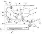
以下、図面を参照しながら本発明の実施形態について説明する。図1は、本発明の一実施形態に係る定着装置を備えた画像形成装置の構成を示す概略側面断面図である。従来例の図9と共通する部分には共通する符号を付して説明を省略する。 Hereinafter, embodiments of the present invention will be described with reference to the drawings. FIG. 1 is a schematic side cross-sectional view showing a configuration of an image forming apparatus including a fixing device according to an embodiment of the present invention. Portions common to FIG. 9 of the conventional example are denoted by common reference numerals and description thereof is omitted.
画像形成装置100内には、帯電、露光、現像及び転写の各工程により所定の画像を形成する画像形成部Pが配設されている。この画像形成部Pには、可視像(トナー像)を担持する感光体ドラム2が配設されており、感光体ドラム2上に形成されたトナー像が、画像形成部Pに隣接して配置されたシート搬送経路を介して搬送されるシート6上に転写され、さらに、定着装置7においてシート6上に定着された後、装置本体より排出される構成となっている。感光体ドラム2を図1おいて時計回りに回転させながら、感光体ドラム2に対する画像形成プロセスが実行される。 In the
次に、画像形成部Pについて詳細に説明する。回転自在に配設された感光体ドラム2の周囲及び上方には、感光体ドラム2を帯電させる帯電器3と、感光体ドラム2に画像情報を露光する露光ユニット4と、感光体ドラム2上にトナー像を形成する現像ユニット5と、感光体ドラム2上に残留した現像剤(トナー)を除去するクリーニング部9が設けられている。 Next, the image forming unit P will be described in detail. Around and around the
先ず、帯電器3によって感光体ドラム2の表面を一様に帯電させ、次いで露光ユニット4によって光照射し、感光体ドラム2上に画像信号に応じた静電潜像を形成する。現像ユニット5にはトナーコンテナ10が内蔵されている。トナーコンテナ10内のトナーは、現像ユニット5により感光体ドラム2上に供給されて静電的に付着することにより、露光ユニット4からの露光により形成された静電潜像に応じたトナー像が形成される。 First, the surface of the
トナー像が転写されるシート6は、給紙カセット11aと、その上方に設けられるスタックバイパス(手差しトレイ)11bに収容されている。給紙カセット11a及びスタックバイパス11bに収容されたシート6は給紙ローラ12及びレジストローラ14を介して画像形成部Pへ供給され、感光体ドラム2の位置へと搬送される。 The
シート6がレジストローラ14から搬送されるタイミングに合わせて画像書き出し信号がONとなり、感光体ドラム2上に画像形成を行う。そして、感光体ドラム2の下部において、所定の転写電圧が印加された転写ローラ16で電界付与することにより、感光体ドラム2上のトナー像がシート6上に転写される。 The image writing signal is turned ON in accordance with the timing at which the
トナー像が転写されたシート6は、感光体ドラム2から離脱し、定着装置7へと搬送される。また、トナー像が転写された後の感光体ドラム2は、引き続き行われる新たな静電潜像の形成に備え、その表面に残留したトナーがクリーニング部9により除去される。画像形成部Pから定着装置7に搬送されたシート6は、定着装置7のハウジング7aに配置された加熱ローラ21及び加圧ローラ23により加熱及び加圧されてトナー像がシート6の表面に定着され、所定の画像が形成される。画像が形成されたシート6は、その後排出ローラ17によって排出トレイ18上に排出される。 The
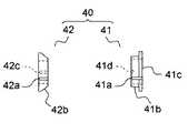
図2は、本実施形態に係る定着装置に用いられる耐熱性断熱部材の側面図であり、図3は、本実施形態に係る定着装置に用いられる耐熱性断熱部材を示す図であって、図3(a)は、第2ブッシュを図2の右側から見た図であり、図3(b)は、第1ブッシュを図2の左側から見た図である。 FIG. 2 is a side view of a heat resistant heat insulating member used in the fixing device according to the present embodiment, and FIG. 3 is a view showing the heat resistant heat insulating member used in the fixing device according to the present embodiment. 3 (a) is a view of the second bush viewed from the right side of FIG. 2, and FIG. 3 (b) is a view of the first bush viewed from the left side of FIG.
また、図4は、本実施形態に係る定着装置に用いられる加熱ローラ及び加圧ローラが第1及び第2軸受に装着される状態を示す側面図であり、図5は、本実施形態に係る定着装置に用いられる加熱ローラが第1軸受に装着された状態を示す側面図であり、図6は、側面断面図である。図9〜図12及び図1と共通する部分には共通する符号を付して説明を省略する。 FIG. 4 is a side view showing a state in which the heating roller and the pressure roller used in the fixing device according to the present embodiment are attached to the first and second bearings, and FIG. 5 is related to the present embodiment. FIG. 6 is a side view showing a state in which a heating roller used in the fixing device is mounted on the first bearing, and FIG. 6 is a side sectional view. Portions common to FIGS. 9 to 12 and 1 are denoted by common reference numerals, and description thereof is omitted.
図2に示すように、定着装置7に用いられるブッシュ(耐熱性断熱部材)40は、第1ブッシュ41(第1部材)と第2ブッシュ(第2部材)42とから構成されている。図2及び図3(b)に示すように、第1ブッシュ41は、一部に開口41aを有する断面C形状から成り、第1軸受(軸受)25の円筒部材21b側の端部とローラ軸21aとの間に装着されたとき(図5及び図6参照)、その先端部(図2の左側端部)が第1軸受25内部で第2ブッシュ42との間に互いに所定間隔を隔てて配置されるような軸方向(図2の左右方向)長さに形成されている。 As shown in FIG. 2, the bush (heat-resistant heat insulating member) 40 used in the
前述と同様に、開口41aにより第1ブッシュ41はローラ軸21aの軸方向とは垂直方向の熱膨張を吸収することができる。また、第1ブッシュ41の外周面41bの軸方向一端部(図2の右側端部)には、フランジ部41cが形成されており、かかるフランジ部41cが第1軸受25と係合することにより、第1ブッシュ41がローラ軸21aと第1軸受25との間から外れることを防止するようになっている。 Similarly to the above, the
また、第1ブッシュ41の外周面41bの径は、第1軸受25の内周面25aの径よりも小さく形成されており、ローラ軸21aの軸方向とは垂直方向の熱膨張を吸収することができるようになっている。また第1ブッシュ41の内周面には、加熱ローラ21のローラ軸21aに形成された切り欠き部21aa(図4参照)に嵌め込まれる突出部41dが形成されており、これにより、ローラ軸21aに対して第1ブッシュ41が空回りすることを防止している。 The diameter of the outer
図2及び図3(a)に示すように、第2ブッシュ42は、一部に開口42aを有する断面C形状からなり、第1軸受25の円筒部材21b側とは反対側の端部とローラ軸21aとの間に装着されたとき(図5及び図6参照)、その先端部(図2の右側端部)が第1軸受25内部で第1ブッシュ41との間に互いに所定間隔を隔てて配置されるような軸方向(図2の左右方向)長さに形成されている。また、前述と同様に、開口42aにより第2ブッシュ42はローラ軸21aの軸方向とは垂直方向の熱膨張を吸収することができる。 As shown in FIGS. 2 and 3A, the
また、第2ブッシュ42の外周面42bにおける図2の右側端部は、第1軸受25と当接可能であり図2の左側から右側に向かって径が小さくなるようにテーパ状に形成されている。また第2ブッシュ42の内周面には、加熱ローラ21のローラ軸21aに形成された切り欠き部21aa(図4参照)に嵌め込まれる突出部42cが形成されており、これにより、ローラ軸21aに対して第2ブッシュ42が空回りすることを防止している。 2 on the outer
そして、図4に示すように、ローラ軸21aの軸方向一端部(ここでは装置前面側端部)に対して第1ブッシュ41を嵌め込み、この状態で第1ブッシュ41を第1軸受25に嵌め込んだ後、軸方向外側(図4の左側)から第2ブッシュ42をローラ軸21aと第1軸受25との間に嵌め込むことにより、ローラ軸21aを第1軸受25に第1及び第2ブッシュ41、42を介して支持することができる。 Then, as shown in FIG. 4, the
また、第2ブッシュ42を装着後、第2ブッシュ42の軸方向外側(図4の左側)端部が、コイルバネ(付勢手段)43によって軸方向に対し第1軸受25の外側から内側(図4の右側)に向かって押圧されるようになっている。また、前述と同様に、加圧ローラ23の芯金23aは第2軸受29に嵌め込むことにより、第2軸受29に支持されるようになっている。なお、第2軸受29は、ここでは図示しないが、前述した図11に示す板金32と同様の板金に固定されている。 In addition, after the
このようにして、図5及び図6に示すように、ローラ軸21aを、ハウジング7a(図1参照)に配置された板金31に固定された第1軸受25に対して、第1及び第2ブッシュ41、42から構成されるブッシュ40を介して支持することができる。このとき、第1ブッシュ41は、軸受25のハウジング7a(図1参照)の内側(図5及び図6の右側)から装着され、第2ブッシュ42は、軸受25のハウジング7a(図1参照)の外側(図5及び図6の左側)から装着されている。図7は、本実施形態に係る定着装置に用いられる第1軸受が傾いた状態を示す側面断面図である。 In this way, as shown in FIGS. 5 and 6, the
従って、前述した様にローラ軸21aの軸方向外側への熱膨張(図7の白抜き矢印)と加圧ローラ23による軸方向への押圧(図4のハッチング矢印)とにより図7に示すように第1軸受25が傾いても、第1及び第2ブッシュ41、42が互いに当接しないため、ローラ軸21aの軸方向の熱膨張を吸収することができる。加えて、第1及び第2ブッシュ41、42を第1軸受25の軸方向両端部にそれぞれ独立して当接させることができる。 Therefore, as described above, as shown in FIG. 7, due to the thermal expansion outward of the
これにより、第1及び第2ブッシュ41、42により第1軸受25を軸方向両端側から挟むことができるため、熱膨張によって生じる第1軸受25の傾きに応じて第1及び第2ブッシュ41、42を第1軸受25と当接させることが可能となる。従って、第1軸受25と第1及び第2ブッシュ41、42との間のガタツキを防止し、異常音の発生を防止することができる。 Thereby, since the 1st bearing 25 can be pinched from the axial direction both ends by the 1st and
なお、第1及び第2ブッシュ41、42の間隔は、ローラ軸21aが軸方向に熱膨張しても互いに当接しないこと、及び第1軸受25のガタツキの防止の程度等を考慮して適宜設計することができる。また、第1軸受25の外周面全周が板金31に固定される構成とすることもできる。かかる場合であっても、上記2つの力が第1軸受25に作用することにより、第1軸受25が歪む等により傾くおそれがあり、この傾きに応じて第1軸受25のガタツキを防止できる。 The distance between the first and
また、本実施形態では、第2ブッシュ42の外周面42bを軸方向に対し第1軸受25の外側から内側に向かって径が小さくなるテーパ状に形成したため、第1軸受25の内周面25aと第2ブッシュ42の外周面42bとの面接触を回避することができる。また、第1軸受25の傾きに応じてテーパ面のいずれかの部分を第1軸受25の軸方向外側(ここでは図7の左下側)端部に十分に当接させることが可能となる。 In the present embodiment, the outer
これにより、複雑な構成を用いることなく第1軸受25と第2ブッシュ42との間のガタツキを、より防止することができ、効果的である。なお、ここでは第2ブッシュ42の外周面42bの一部をテーパ状に形成したが、外周面42b全体をテーパ状に形成することもできる。また、第1ブッシュ41の外周面41bをテーパ状に形成することもできる。 Thereby, rattling between the
かかる場合、コイルバネ43と同様のコイルバネを用いて第1ブッシュ42を第1軸受25の軸方向外側から内側(図7の左側)に付勢することもできる。また、第1及び第2ブッシュ41、42の両外周面41b、42bをテーパ状に形成することもできる。これにより、さらに効果的に第1軸受25のガタツキを防止することができる。 In such a case, the
また、第2ブッシュ42の外周面42bをテーパ状に形成する代わりに第1ブッシュ41と同様の形状に形成し、外周面がテーパ状に形成されていない2つの第1及び第2ブッシュ41、42を、第1軸受25とローラ軸21aとの間に嵌め込むこともできる。 Moreover, instead of forming the outer
また、本実施形態では、第2ブッシュ42を軸方向に対し第1軸受25の外側から内側に付勢するコイルバネ43を設けたため、第1軸受25が傾いてもその変化に応じてより確実に、第2ブッシュ42を第1軸受25に十分に当接させることができる。これにより、ローラ軸21aをより安定して支持すると共に、異常音の発生を防止することが可能となる。特に、ここでは第2ブッシュ42の外周面42bをテーパ状に形成したため、テーパ面を第1軸受25に、より確実に当接させることができ、効果的である。 Further, in the present embodiment, the
しかし、コイルバネ43は、本発明の必須構成要素ではなく、コイルバネ43を用いない構成とすることもできる。また、ここでは、第2ブッシュ42を付勢するコイルバネ43を設けたが、その他、板バネ等により第2ブッシュ42を付勢することもできる。また、第2ブッシュ42を付勢するコイルバネ43に加え、第1ブッシュ41を軸方向に対し第1軸受25の外側から内側(図4の左側)に付勢するコイルバネを設けることもできる。 However, the
また、ここではローラ軸21aの装置前面側端部に第1及び第2ブッシュ41、42を適用したが、装置背面側端部にも勿論適用することができ、両端部に適用することもできる。なお、ローラ軸21aの軸方向一端部は、駆動ギア(図示せず)等と連結されてガタツキの発生が少ない場合もあるため、かかる装置構成等も考慮してローラ軸21aの軸方向に対し駆動連結側とは反対側の端部のみに第1及び第2ブッシュ41、42を適用すること等もできる。 In addition, here, the first and
その他本発明は、上記実施形態に限定されず、本発明の趣旨を逸脱しない範囲で種々の変更が可能である。例えば第1及び第2ブッシュ41、42の形状等は、上記実施形態に特に限定されるものではない。その他例えば、図8(a)に示すように、第2ブッシュ42の軸方向内側端面(図の右側端面)の一部を軸方向内側(図の右側)に突出させると共に傾斜させ、第1軸受25の内周面25aの軸方向外側(図8(b)の左側)端部と当接可能な傾斜面42dを形成することもできる。 In addition, this invention is not limited to the said embodiment, A various change is possible in the range which does not deviate from the meaning of this invention. For example, the shape and the like of the first and
これにより、図8(b)に示すように、少なくとも傾斜面42dのいずれか(ここでは上方部)を、第1軸受25の内周面25aの上記外側端部と当接させることが可能となり、第1軸受25のガタツキを防止することができる。その他の構成は上記実施形態と同様である。なお、第1ブッシュ41も同様の構成とすることができるのは勿論である。 As a result, as shown in FIG. 8B, at least one of the
また、上記実施形態では、第1及び第2ブッシュ41、42に開口41a、42a及び突起部41d、42c、第1ブッシュ41にフランジ部41cを形成したが、これらは本発明の必須構成要素ではなく、装置構成等に応じて適宜設けることができる。 Moreover, in the said embodiment, although opening 41a, 42a and
また、上記実施形態では、本発明の加熱装置の一例として、加熱ローラ21と加圧ローラ23とにより形成された定着ニップ部にてシート6を挿通させてシート6上に担持された未定着のトナー像を定着する定着装置7に適用することにより、異常音の発生が防止されたトナー像の定着を行うことができる。しかし、本発明の加熱装置は、本実施形態に特に限定されるものではなく、その他の加熱装置にも適用することができる。 In the above-described embodiment, as an example of the heating device of the present invention, the
また、本発明の加熱装置は図1に示したモノクロプリンタに限らず、タンデム式のカラープリンタ、デジタル複合機やカラー複写機、アナログ方式のモノクロ複写機、或いはファクシミリ等の、電子写真プロセスを用いた種々の画像形成装置に適用できる。 The heating apparatus of the present invention is not limited to the monochrome printer shown in FIG. 1, and uses an electrophotographic process such as a tandem color printer, a digital multifunction machine, a color copying machine, an analog monochrome copying machine, or a facsimile. The present invention can be applied to various image forming apparatuses.
本発明は、ハウジングと、該ハウジング内に配置され、加熱源が内蔵された加熱ローラと、前記ハウジングに支持されると共に前記加熱ローラのローラ軸を回転自在に支持する軸受と、前記ローラ軸と軸受との間に挿入される耐熱性断熱部材と、を備えた加熱装置であって、前記耐熱性断熱部材は、前記軸受の前記ハウジングの内側から装着される第1部材と、前記軸受の前記ハウジングの外側から装着される第2部材と、を有するものである。 The present invention includes a housing, a heating roller disposed in the housing and including a heating source, a bearing supported by the housing and rotatably supporting a roller shaft of the heating roller, and the roller shaft. A heat-resistant heat-insulating member inserted between the bearing and the heat-resistant heat-insulating member, the heat-resistant heat-insulating member being mounted from the inside of the housing of the bearing; And a second member mounted from the outside of the housing.
これにより、軸方向の熱膨張を吸収すると共に、2つの部材により軸受を軸方向両端部側から挟むことができるため、熱膨張によって生じる軸受の傾きに応じて耐熱性断熱部材を軸受と当接させることが可能となり、軸受と耐熱性断熱部材との間のガタツキを防止し、異常音の発生を防止することができる。 As a result, the thermal expansion in the axial direction can be absorbed and the bearing can be sandwiched between the two axial ends by the two members, so that the heat-resistant heat insulating member abuts the bearing according to the inclination of the bearing caused by the thermal expansion. Therefore, it is possible to prevent rattling between the bearing and the heat-resistant heat insulating member, and to prevent the generation of abnormal noise.
また、第2部材を、ローラ軸の軸方向に対し軸受の外側から内側に向かって径が小さくなるテーパ状に形成すると共に軸受と当接可能とすることにより、軸受の内周面と第2部材の外周面との面接触を回避し、軸受の傾きに応じてテーパ面のいずれかの位置を軸受の軸方向両端部に十分に当接させることが可能となるため、複雑な構成を用いることなく軸受と耐熱性断熱部材との間のガタツキを、より防止することができ、効果的である。 In addition, the second member is formed in a tapered shape whose diameter decreases from the outer side to the inner side of the bearing with respect to the axial direction of the roller shaft, and the second member can be brought into contact with the bearing. A complicated configuration is used because surface contact with the outer peripheral surface of the member can be avoided, and any position of the tapered surface can be sufficiently brought into contact with both ends in the axial direction of the bearing according to the inclination of the bearing. The backlash between the bearing and the heat-resistant heat insulating member can be prevented more effectively, and is effective.
また、第2部材を、該第2部材が軸受を軸方向の外側から内側に向かって押圧するように付勢する付勢手段を設けることにより、軸受が傾いてもその傾きに応じてより確実に耐熱性断熱部材を軸受に当接させることが可能となるため、ローラ軸をより安定して支持すると共に、異常音の発生を防止することができる。特に第2部材の外周面を上記テーパ状に形成した場合、より効果的である。 Further, by providing a biasing means for biasing the second member so that the second member presses the bearing from the outer side to the inner side in the axial direction, even if the bearing is tilted, the second member is more reliably adapted to the tilt. In addition, since the heat-resistant heat insulating member can be brought into contact with the bearing, the roller shaft can be supported more stably and the occurrence of abnormal noise can be prevented. In particular, it is more effective when the outer peripheral surface of the second member is formed in the tapered shape.
また、加熱装置が加熱ローラに所定の圧力で当接する加圧ローラを備え、加熱装置を、加熱ローラと加圧ローラとにより形成された定着ニップ部にて記録媒体を挿通させて記録媒体上に担持された未定着のトナー像を定着する定着装置として用いることにより、異常音の発生が防止されたトナー像の定着を行うことができる。また、上記加熱装置を備えた画像形成装置とすることにより、異常音の発生が防止された画像形成を行うことができる。 Further, the heating device includes a pressure roller that contacts the heating roller with a predetermined pressure, and the heating device is inserted on the recording medium through the fixing nip formed by the heating roller and the pressure roller. By using the carried unfixed toner image as a fixing device for fixing, it is possible to fix the toner image in which abnormal noise is prevented. Further, by forming an image forming apparatus including the heating device, it is possible to perform image formation in which abnormal noise is prevented from being generated.
6 シート(記録媒体)
7 定着装置(加熱装置)
7a ハウジング
21 加熱ローラ
21a ローラ軸
21c 光源(加熱源)
23 加圧ローラ
23a 芯金
25 第1軸受(軸受)
25a 内周面
29 第2軸受
40 ブッシュ(耐熱性断熱部材)
41 第1ブッシュ(第1部材)
41a 開口
41b 外周面
42 第2ブッシュ(第2部材)
42a 開口
42b 外周面
42d 傾斜面
43 コイルバネ(付勢手段)6 sheet (recording medium)
7 Fixing device (heating device)
23
25a Inner
41 First bush (first member)
Claims (5)
Translated fromJapanese該ハウジング内に配置され、加熱源が内蔵された加熱ローラと、
前記ハウジングに支持されると共に前記加熱ローラのローラ軸を回転自在に支持する軸受と、
前記ローラ軸と軸受との間に挿入される耐熱性断熱部材と、を備えた加熱装置であって、
前記耐熱性断熱部材は、前記軸受の前記ハウジングの内側から装着される第1部材と、前記軸受の前記ハウジングの外側から装着される第2部材と、を有することを特徴とする加熱装置。A housing;
A heating roller disposed within the housing and incorporating a heating source;
A bearing supported by the housing and rotatably supporting a roller shaft of the heating roller;
A heat-resistant heat insulating member inserted between the roller shaft and the bearing,
The heat-resistant heat insulating member has a first member mounted from the inside of the housing of the bearing and a second member mounted from the outside of the housing of the bearing.
Priority Applications (1)
| Application Number | Priority Date | Filing Date | Title |
|---|---|---|---|
| JP2009073117AJP2010224331A (en) | 2009-03-25 | 2009-03-25 | Heating device and image forming apparatus having the same |
Applications Claiming Priority (1)
| Application Number | Priority Date | Filing Date | Title |
|---|---|---|---|
| JP2009073117AJP2010224331A (en) | 2009-03-25 | 2009-03-25 | Heating device and image forming apparatus having the same |
Publications (1)
| Publication Number | Publication Date |
|---|---|
| JP2010224331Atrue JP2010224331A (en) | 2010-10-07 |
Family
ID=43041563
Family Applications (1)
| Application Number | Title | Priority Date | Filing Date |
|---|---|---|---|
| JP2009073117APendingJP2010224331A (en) | 2009-03-25 | 2009-03-25 | Heating device and image forming apparatus having the same |
Country Status (1)
| Country | Link |
|---|---|
| JP (1) | JP2010224331A (en) |
Cited By (2)
| Publication number | Priority date | Publication date | Assignee | Title |
|---|---|---|---|---|
| JP2015129843A (en)* | 2014-01-07 | 2015-07-16 | ブラザー工業株式会社 | fixing device |
| US11630406B2 (en) | 2020-09-30 | 2023-04-18 | Kyocera Document Solutions Inc. | Fixing device and image forming apparatus |
- 2009
- 2009-03-25JPJP2009073117Apatent/JP2010224331A/enactivePending
Cited By (2)
| Publication number | Priority date | Publication date | Assignee | Title |
|---|---|---|---|---|
| JP2015129843A (en)* | 2014-01-07 | 2015-07-16 | ブラザー工業株式会社 | fixing device |
| US11630406B2 (en) | 2020-09-30 | 2023-04-18 | Kyocera Document Solutions Inc. | Fixing device and image forming apparatus |
Similar Documents
| Publication | Publication Date | Title |
|---|---|---|
| US9804547B2 (en) | Fixing device and image forming apparatus that reduce rotation failure of fixing belt | |
| JP2005070376A (en) | Fixing apparatus and image forming apparatus | |
| JP2010217492A (en) | Fixing device and image forming apparatus equipped with the same | |
| US8107870B2 (en) | Fusing device and image forming apparatus using the same | |
| CN106200324A (en) | Fixing device and image processing system | |
| JP2010224331A (en) | Heating device and image forming apparatus having the same | |
| JP6182115B2 (en) | Fixing apparatus and image forming apparatus | |
| JP2008107390A (en) | Fixing device and image forming apparatus | |
| JP6217502B2 (en) | Fixing apparatus and image forming apparatus | |
| CN103425027A (en) | Fixing device and image forming apparatus | |
| JP4717549B2 (en) | Fixing device | |
| US9164448B2 (en) | Fixing device and image forming apparatus | |
| JP6471711B2 (en) | Fixing apparatus and image forming apparatus | |
| JP7631943B2 (en) | Fixing device and image forming apparatus equipped with said fixing device | |
| US10073390B2 (en) | Fixing device and image forming apparatus including the same | |
| JP6122797B2 (en) | Fixing apparatus and image forming apparatus | |
| JP6819456B2 (en) | Fixing device and image forming device | |
| JP6083393B2 (en) | Fixing apparatus and image forming apparatus | |
| JP4490934B2 (en) | Fixing device and image forming apparatus having the same | |
| JP2006133327A (en) | Fixing apparatus and image forming apparatus | |
| JP4745712B2 (en) | Fixing device | |
| JP2009122147A (en) | Paper separation device for fixing unit of image forming apparatus | |
| JP2007140320A (en) | Fixing apparatus and image forming apparatus using the same | |
| JP2014191136A (en) | Fixing device and image forming apparatus | |
| JP2007010999A (en) | Fixing device |