JP2010220830A - Biological information measuring device - Google Patents
Biological information measuring deviceDownload PDFInfo
- Publication number
- JP2010220830A JP2010220830AJP2009071751AJP2009071751AJP2010220830AJP 2010220830 AJP2010220830 AJP 2010220830AJP 2009071751 AJP2009071751 AJP 2009071751AJP 2009071751 AJP2009071751 AJP 2009071751AJP 2010220830 AJP2010220830 AJP 2010220830A
- Authority
- JP
- Japan
- Prior art keywords
- button switch
- push button
- meter
- outer peripheral
- measurement
- Prior art date
- Legal status (The legal status is an assumption and is not a legal conclusion. Google has not performed a legal analysis and makes no representation as to the accuracy of the status listed.)
- Pending
Links
Images


Landscapes
- Measurement And Recording Of Electrical Phenomena And Electrical Characteristics Of The Living Body (AREA)
Abstract
Description
Translated fromJapanese本発明は、生体情報測定装置に関する。 The present invention relates to a biological information measuring device.
従来、測定計に被測定者が乗ることで、この被測定者の生体に関する情報を測定する生体情報測定装置がある。 2. Description of the Related Art Conventionally, there is a biological information measuring device that measures information related to a living body of the measured person by placing the measured person on the measuring meter.
生体に関する情報が体重であれば、生体情報測定装置は体重計(測定計)であり、生体に関する情報が皮下脂肪厚であれば、生体情報測定装置は体組成計(測定計…体重計を兼ねることもある。)である(特許文献1参照)。 If the information related to the living body is body weight, the biological information measuring device is a scale (measurement meter), and if the information related to the living body is subcutaneous fat thickness, the biological information measuring device also serves as a body composition meter (measurement meter ... weight scale). (See Patent Document 1).
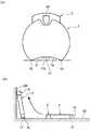
図5(a)に示すように、前記のような測定計21の外形状は、通常は四角状や円状等で、略平板状(偏平状)に形成されている。そして、この測定計21の外周面に、外方に突出する測定開始用プッシュボタンスイッチ22が設置されているものがある。ここでプッシュボタンスイッチ22とは、要するに、押すことでオン・オフするスイッチであり、その他、シーソースイッチやスティックスイッチ等も含まれるものである。 As shown in FIG. 5A, the outer shape of the
このように、プッシュボタンスイッチ22を測定計21の外周面から外方に突出させておけば、測定計21に乗る被測定者は、立ったままの姿勢で、プッシュボタンスイッチ22を足で蹴って押すことができるので、簡単に測定を開始できるという利点がある。そのために、プッシュボタンスイッチ22は、測定計21に乗る側、つまり、前面21a側に配置されている。 In this way, if the
ところで、図5(b)に示すように、測定計21を床面23に置いたまま保管すると、邪魔になることがあるから、矢印のように、壁面24に立てかけて保管することがある。 By the way, as shown in FIG. 5 (b), if the
この場合、測定計21の測定値等の表示部21bが上側であるという意識が働いて、プッシュボタンスイッチ22を床面23側とすることが多い。 In this case, the
しかしながら、プッシュボタンスイッチ22を床面23側として、測定計21を壁面24に立てかけて保管した場合、測定計21の自重がプッシュボタンスイッチ22に作用するようになる。これにより、プッシュボタンスイッチ22が床面23に押し付けられることで誤ってオンし、このオン状態が長く続くことで、測定計21に内蔵している電池が著しく消耗するという問題があった。 However, when the
本発明は、前記問題を解消するためになされたもので、プッシュボタンスイッチを床面側として、測定計を壁面に立てかけて保管した場合でも、プッシュボタンスイッチが誤ってオンしないように工夫した生体情報測定装置を提供することを目的とするものである。 The present invention has been made to solve the above-described problem. A living body devised so that the push button switch is not accidentally turned on even when the push button switch is on the floor side and the measurement meter is stood against the wall surface. An object of the present invention is to provide an information measuring device.
前記課題を解決するために、本発明は、測定計に被測定者が乗ることで、この被測定者の生体情報を測定する生体情報測定装置において、前記測定計は、略平板状に形成され、この測定計の外周面に、外方に突出する測定開始用プッシュボタンスイッチが設置され、このプッシュボタンスイッチの両側方に位置する測定計の外周面に、プッシュボタンスイッチの先端よりも外方に突出する突出部が形成されていることを特徴とする生体情報測定装置を提供するものである。 In order to solve the above-described problems, the present invention provides a biological information measuring apparatus for measuring biological information of a measurement subject by placing the measurement subject on the measurement meter, and the measurement meter is formed in a substantially flat plate shape. On the outer peripheral surface of this measuring meter, a push button switch for starting measurement that protrudes outward is installed. On the outer peripheral surface of the measuring meter located on both sides of this push button switch, the outer side of the push button switch is more outward. The present invention provides a biological information measuring device characterized in that a protruding portion that protrudes from the surface is formed.
請求項2のように、前記プッシュボタンスイッチが設置される部位の測定計の外周面は円弧部に形成され、この円弧部の中央部分にプッシュボタンスイッチが設置され、この円弧部の両端部分は、プッシュボタンスイッチの先端よりも外方に突出する突出部となる構成とすることができる。 As in
本発明によれば、測定開始用プッシュボタンスイッチの両側方に位置する測定計の外周面に、プッシュボタンスイッチの先端よりも外方に突出する突出部を形成したものである。したがって、プッシュボタンスイッチを床面側として、測定計を壁面に立てかけて保管した場合でも、突出部が床面に接することで、プッシュボタンスイッチが床面に押し付けられることがなくなる。その結果、プッシュボタンスイッチが誤ってオンしなくなるので、測定計に内蔵している電池の無駄な消耗がなくなる。また、測定計の外周面に突出部を形成するだけであるから、構造もきわめて簡単である。 According to the present invention, the protruding portion that protrudes outward from the tip of the push button switch is formed on the outer peripheral surface of the measuring meter located on both sides of the push button switch for starting measurement. Therefore, even when the push button switch is on the floor side and the measuring meter is stood against the wall surface, the push button switch is not pressed against the floor surface because the protruding portion is in contact with the floor surface. As a result, the push button switch does not turn on accidentally, and the battery built in the measuring instrument is not wasted. Further, since only the protrusion is formed on the outer peripheral surface of the measuring meter, the structure is very simple.
請求項2によれば、プッシュボタンスイッチの設置部位の外周面を円弧部とし、その中央部分にプッシュボタンスイッチを設置すれば、その両端部分を突出部とできるので、合理的であるとともに、デザイン的にも違和感がなくなる。 According to
以下、本発明を実施するための形態について、図面を参照しながら詳細に説明する。図1(a)は、体重計(測定計)1にハンドユニット(皮下脂肪厚測定ユニット)2を取り付けた状態の斜視図、図2は、体重計1からハンドユニット2を取り外して、生体インピーダンスを測定している状態の斜視図である。 Hereinafter, embodiments for carrying out the present invention will be described in detail with reference to the drawings. FIG. 1A is a perspective view of a state in which a hand unit (subcutaneous fat thickness measurement unit) 2 is attached to a weight scale (measurement meter) 1, and FIG. 2 shows a bioimpedance by removing the
この体重計1は、体組成体重計であり、この体重計1に被測定者が左右の足を乗せると、その体重をハンドユニット2の表示部2Aで表示することができる。 The
この体重計1の左右の足を乗せる部分には、印加電極3と測定電極4がそれぞれ設けられて、印加電極3と測定電極4との間で足の生体インピーダンスを測定することができる。この足の生体インピーダンスに基づく体脂肪(内臓脂肪)率は、ハンドユニット2の表示部2Aで表示することができる。 An
また、ハンドユニット2の左右の手で把持する把持部10,11には、印加電極(図示せず。)と測定電極6がそれぞれ設けられて、印加電極と測定電極6との間で手の生体インピーダンスを測定することができる。この手の生体インピーダンスに基づく体脂肪率は、ハンドユニット2の表示部2Aで表示することができる。 In addition, the
そして、ハンドユニット2と体重計1は、フレキシブルなコード7で電気的に接続されている。このコード7は、体重計1側とハンドユニット2側の測定情報とを一元的に管理する等のためのものであり、体重計1で測定した体重や電極3〜6で測定した体脂肪率等をハンドユニット2の表示部2Aで表示することができる。なお、電極3〜6で生体インピーダンスを測定する方法は、公知であるので、これ以上の説明は省略する。 The
ハンドユニット2の正面には、体脂肪率等を表示する液晶ディスプレイ等の表示部2Aと、身長・体重・性別等を入力する各種スイッチ15が配列された操作部2Bとが設けられている。 On the front surface of the
ハンドユニット2と体重計1とを電気的に接続するコード7は、体重計1内に設けられたコードリール(図示せず。)に巻き取り・引き出し可能に巻き付けられている。 A
前記のように、ハンドユニット2を備えた体重計1を用いて、生体インピーダンスを測定する場合には、図2に示したように、ハンドユニット2を体重計1から取り外して、被測定者は体重計1の上に乗る。ハンドユニット2には、被測定者の身長・性別・年齢等を予め入力しておく。なお、体重は、体重計1で自動的に測定されるので入力する必要は無い。 As described above, when the bioimpedance is measured using the
そして、被測定者は、ハンドユニット2の把持部10,11を両手で把持し、巻き取り方向に付勢されたコード7を体重計1内のコードリールから引き出しながら、両腕を真っ直ぐに伸ばした状態にハンドユニット2を保持する。 Then, the person to be measured grips the
このようにして、体重計1で測定した体重や各電極3〜6で測定した手足の生体インピーダンスに基づく体脂肪率は、前述のように、ハンドユニット2の表示部2Aで表示されるようになる。 In this way, the body fat percentage based on the body weight measured by the
前記ハンドユニット2に、測定開始用プッシュボタンスイッチを設けることができる。しかし、体重計1にハンドユニット2を取り付けた状態で、体重だけを測定するような場合のために、円形で略平板状に形成された体重計1の外周面に、外方に突出する測定開始用プッシュボタンスイッチ17が設置されている。 The
これにより、体重計1に乗る被測定者は、立ったままの姿勢で、プッシュボタンスイッチ17を足で蹴って押すことができるので、簡単に測定を開始できる。そのために、プッシュボタンスイッチ17は、体重計1に乗る側、つまり、前面1a側に配置されている。 As a result, the person to be measured who rides on the
このプッシュボタンスイッチ17の両側方に位置する体重計1の外周面に、プッシュボタンスイッチ17の先端17aよりも外方に突出する(一点鎖線a参照)突出部1bが形成されている。 On the outer peripheral surface of the
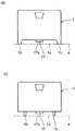
具体的には、図3(a)にも示すように、プッシュボタンスイッチ17が設置される前面1aに円弧部1cが形成されている。そして、この円弧部1cの中央部分にプッシュボタンスイッチ17が設置され、この円弧部1cの両端部分は、プッシュボタンスイッチ17の先端17aよりも外方に突出する突出部1bとなる。 Specifically, as shown in FIG. 3A, a
前記体組成体重計1は、プッシュボタンスイッチ17の両側方に位置する体重計1の前面1aに、プッシュボタンスイッチ17の先端17aよりも外方に突出する突出部1bを形成したものである。 The body
そして、図3(b)に示すように、体重計1を床面23に置いたまま保管すると、邪魔になることがある。そこで、矢印のように、プッシュボタンスイッチ17を床面23側として、体重計1を壁面24に立てかけて保管する場合には、突出部1bが床面23に接することで、プッシュボタンスイッチ17が床面23に押し付けられることがなくなる。特に、起毛を有するカーペットが床面23に敷かれているような場合には、プッシュボタンスイッチ17が起毛に隠れて見えなくなるような時には有利である。 And as shown in FIG.3 (b), when the
その結果、プッシュボタンスイッチ17が誤ってオンしなくなるので、体重計1に内蔵している電池の無駄な消耗がなくなる。また、体重計1の外周面である前面1aに突出部1bを形成するだけであるから、構造もきわめて簡単である。 As a result, the
さらに、プッシュボタンスイッチ17の設置部位の前面1aを円弧部1cとし、その中央部分にプッシュボタンスイッチ17を設置すれば、その両端部分を突出部1bとできるので、合理的であるとともに、デザイン的にも違和感がなくなる。 Furthermore, if the
前記実施形態では、体重計1の前面1aに円弧部1cを形成し、この円弧部1cの両端部分を突出部1bとしたものであったが、図4(a)のように、体重計1が四角状であれば、真っ直ぐな前面1aの両端に突出部1bを形成することもできる。また、突出部1bは、体重計1の前面1aから一体に突出させる必要はなく、図4(b)のように、別体の突出部1bを体重計1の前面1aにねじ等で取付けることもできる。 In the embodiment described above, the
1 体重計(測定計)
1a 前面(外周面)
1b 突出部
1c 円弧部
2 ハンドユニット(皮下脂肪厚測定ユニット)
7 コード
17 測定開始用プッシュボタンスイッチ
17a 先端1 Weight scale (measurement meter)
1a Front (outer peripheral surface)
7
Claims (2)
Translated fromJapanese前記測定計は、略平板状に形成され、この測定計の外周面に、外方に突出する測定開始用プッシュボタンスイッチが設置され、このプッシュボタンスイッチの両側方に位置する測定計の外周面に、プッシュボタンスイッチの先端よりも外方に突出する突出部が形成されていることを特徴とする生体情報測定装置。In the biological information measuring device that measures the biological information of the measurement subject by placing the measurement subject on the measurement meter,
The measuring meter is formed in a substantially flat plate shape, and a measurement start push button switch protruding outward is installed on the outer peripheral surface of the measuring meter, and the outer peripheral surface of the measuring meter located on both sides of the push button switch. Further, the living body information measuring apparatus is characterized in that a protruding portion protruding outward from the tip of the push button switch is formed.
Priority Applications (1)
| Application Number | Priority Date | Filing Date | Title |
|---|---|---|---|
| JP2009071751AJP2010220830A (en) | 2009-03-24 | 2009-03-24 | Biological information measuring device |
Applications Claiming Priority (1)
| Application Number | Priority Date | Filing Date | Title |
|---|---|---|---|
| JP2009071751AJP2010220830A (en) | 2009-03-24 | 2009-03-24 | Biological information measuring device |
Publications (1)
| Publication Number | Publication Date |
|---|---|
| JP2010220830Atrue JP2010220830A (en) | 2010-10-07 |
Family
ID=43038680
Family Applications (1)
| Application Number | Title | Priority Date | Filing Date |
|---|---|---|---|
| JP2009071751APendingJP2010220830A (en) | 2009-03-24 | 2009-03-24 | Biological information measuring device |
Country Status (1)
| Country | Link |
|---|---|
| JP (1) | JP2010220830A (en) |
Cited By (2)
| Publication number | Priority date | Publication date | Assignee | Title |
|---|---|---|---|---|
| JP2013226189A (en)* | 2012-04-24 | 2013-11-07 | Denso Corp | Blood pressure measurement device |
| JP2013230291A (en)* | 2012-05-01 | 2013-11-14 | Denso Corp | Blood pressure measurement apparatus |
Citations (4)
| Publication number | Priority date | Publication date | Assignee | Title |
|---|---|---|---|---|
| JP2005106552A (en)* | 2003-09-29 | 2005-04-21 | Pigeon Corp | Digital display scale |
| JP2006254981A (en)* | 2005-03-15 | 2006-09-28 | Tanita Corp | Women's physical management device |
| WO2007129521A1 (en)* | 2006-05-10 | 2007-11-15 | Omron Healthcare Co., Ltd. | Body composition measuring instrument |
| JP2009092519A (en)* | 2007-10-09 | 2009-04-30 | Nintendo Co Ltd | Load detection program and load detection device |
- 2009
- 2009-03-24JPJP2009071751Apatent/JP2010220830A/enactivePending
Patent Citations (4)
| Publication number | Priority date | Publication date | Assignee | Title |
|---|---|---|---|---|
| JP2005106552A (en)* | 2003-09-29 | 2005-04-21 | Pigeon Corp | Digital display scale |
| JP2006254981A (en)* | 2005-03-15 | 2006-09-28 | Tanita Corp | Women's physical management device |
| WO2007129521A1 (en)* | 2006-05-10 | 2007-11-15 | Omron Healthcare Co., Ltd. | Body composition measuring instrument |
| JP2009092519A (en)* | 2007-10-09 | 2009-04-30 | Nintendo Co Ltd | Load detection program and load detection device |
Non-Patent Citations (4)
| Title |
|---|
| JPN7012005326; ゲーム環境向上委員会: '不定期連載ゲームグッズ研究所【第155回】' GAME Watch , 20080408* |
| JPN7012005327; ゲーム環境向上委員会: '不定期連載ゲームグッズ研究所【第151回】' GAME Watch , 20080310* |
| JPN7012005328; バランスWiiボード 取扱説明書 , 2007, 1,6,15,20, 任天堂株式会社* |
| JPN7012005329; 家族で健康 WiiFit , 2007* |
Cited By (2)
| Publication number | Priority date | Publication date | Assignee | Title |
|---|---|---|---|---|
| JP2013226189A (en)* | 2012-04-24 | 2013-11-07 | Denso Corp | Blood pressure measurement device |
| JP2013230291A (en)* | 2012-05-01 | 2013-11-14 | Denso Corp | Blood pressure measurement apparatus |
Similar Documents
| Publication | Publication Date | Title |
|---|---|---|
| JP5839213B1 (en) | Intraoral moisture meter | |
| JP4609463B2 (en) | Hand unit for bioimpedance measurement | |
| WO2007052450A1 (en) | Body composition measuring device | |
| JP5589480B2 (en) | Body fat measuring device | |
| JP5593767B2 (en) | Body fat measuring device | |
| JP2006247209A (en) | Body composition measuring device | |
| JP5426964B2 (en) | Health measuring device | |
| JP2010220830A (en) | Biological information measuring device | |
| JP2007301093A (en) | Body composition measuring device | |
| JP4636152B2 (en) | Scale with a subcutaneous fat thickness measurement unit | |
| JP3815339B2 (en) | Health care guideline advice device | |
| EP1092389B1 (en) | Bioelectrical impedance measuring apparatus with handgrip | |
| JP4228468B2 (en) | Body fat measuring device | |
| JP2004141186A (en) | Apparatus for advising health care guide | |
| JP2003070762A (en) | Health management index advising device | |
| JP3888207B2 (en) | Biological information measuring device | |
| JP2002263077A (en) | Biological information measurement device | |
| JP4069500B2 (en) | Body fat measuring device | |
| JP2010220855A (en) | Body composition meter | |
| JP2010240211A (en) | Biometric device | |
| JPWO2013024567A1 (en) | Body moisture meter and display control method thereof | |
| JP5010005B2 (en) | Biological information measuring device | |
| JP2004129779A (en) | Biological information measurement device | |
| JP2004144571A (en) | Weighing machine and health care guide advice apparatus | |
| JP3508633B2 (en) | Body fat scale |
Legal Events
| Date | Code | Title | Description |
|---|---|---|---|
| A621 | Written request for application examination | Free format text:JAPANESE INTERMEDIATE CODE: A621 Effective date:20110523 | |
| A711 | Notification of change in applicant | Free format text:JAPANESE INTERMEDIATE CODE: A712 Effective date:20120111 | |
| A131 | Notification of reasons for refusal | Free format text:JAPANESE INTERMEDIATE CODE: A131 Effective date:20121030 | |
| A977 | Report on retrieval | Free format text:JAPANESE INTERMEDIATE CODE: A971007 Effective date:20121031 | |
| A521 | Written amendment | Free format text:JAPANESE INTERMEDIATE CODE: A523 Effective date:20121206 | |
| A02 | Decision of refusal | Free format text:JAPANESE INTERMEDIATE CODE: A02 Effective date:20130507 |