JP2010214132A - Arm holder - Google Patents
Arm holderDownload PDFInfo
- Publication number
- JP2010214132A JP2010214132AJP2010128439AJP2010128439AJP2010214132AJP 2010214132 AJP2010214132 AJP 2010214132AJP 2010128439 AJP2010128439 AJP 2010128439AJP 2010128439 AJP2010128439 AJP 2010128439AJP 2010214132 AJP2010214132 AJP 2010214132A
- Authority
- JP
- Japan
- Prior art keywords
- main body
- arm holder
- arm
- belt
- holder according
- Prior art date
- Legal status (The legal status is an assumption and is not a legal conclusion. Google has not performed a legal analysis and makes no representation as to the accuracy of the status listed.)
- Granted
Links
Images


Landscapes
- External Artificial Organs (AREA)
Abstract
Translated fromJapaneseDescription
Translated fromJapanese本発明は、腕ホルダーに関するものであり、より詳しくは、例えば人工透析治療を受ける患者の腕を固定する腕ホルダーに関する。 The present invention relates to an arm holder, and more particularly to an arm holder for fixing an arm of a patient undergoing an artificial dialysis treatment, for example.
近年、日本で約28万人強が人工透析の治療を受けており、毎年約1万人ずつ透析患者が増えている。人工透析とは、医療行為のひとつで腎臓の機能を人工的に代替することである。腎不全に陥った患者が尿毒症になるのを防止するには、外的な手段で血液の「老廃物除去」「電解質維持」「水分量維持」を行わなければならない。この治療を人工透析と呼び、人工腎、血液浄化と呼ばれることもある。 In recent years, about 280,000 people in Japan have been treated with artificial dialysis, and about 10,000 dialysis patients are increasing every year. Artificial dialysis is an artificial replacement of the kidney function as a medical practice. In order to prevent patients suffering from renal failure from becoming uremia, it is necessary to perform “removal of waste products”, “electrolyte maintenance”, and “water content maintenance” of blood by external means. This treatment is called artificial dialysis and is sometimes called artificial kidney or blood purification.
人工透析には血液透析と腹膜透析の2つの療法があるが、ダイアライザー(透析器)を使った血液透析を行う人が圧倒的に多い。血液透析は、血液を1度体の外に出して人工腎臓(ダイアライザー)を通して老廃物や過剰な水分を取り除き、また体の中に戻す治療法である。そのためには、血液の「送り出し口」「戻り口」である「シャント」をつくるための手術が必要となる。 Artificial dialysis has two therapies, hemodialysis and peritoneal dialysis, but the majority of people perform hemodialysis using a dialyzer. Hemodialysis is a treatment that takes blood out of the body once, removes waste and excess water through an artificial kidney (dialyzer), and returns it to the body. For this purpose, an operation for creating a “shunt” that is a “delivery port” or “return port” of blood is required.
シャントとは、十分な血液量をダイアライザに送るための、血液量が豊富な太い血管のことである。シャントは、手術により腕の動脈と静脈を縫い合わせて作られる。一般的に、シャントは、利き腕と反対側の肘と手首の間に作られることが多い。 A shunt is a thick blood vessel that is rich in blood to send a sufficient amount of blood to the dialyzer. Shunts are made by stitching the arteries and veins of the arm by surgery. In general, shunts are often made between the elbow and wrist opposite the dominant arm.
透析中の患者は、約4時間程度の間、送り出し用と戻り用の2本の針をシャントに刺した状態で安静にしていることが求められる。針がシャントから抜けてしまうことを防止するために、透析が行われている方の腕は固定される必要がある。そのために、患者の腕を固定する腕ホルダーが使用されている。 The patient undergoing dialysis is required to rest for about 4 hours with two needles for feeding and returning inserted into the shunt. In order to prevent the needle from coming out of the shunt, the arm on which dialysis is being performed needs to be fixed. For this purpose, an arm holder for fixing a patient's arm is used.
ところで、透析は長時間に渡ることから、その間、医師や看護師が患者に付き添っていることは難しい。そのため、抜針により患者から出血し、しかもその発見が遅れるという事故が発生し得る。そのような事故を未然に防止するため、上述の腕ホルダーと併せて、抜針による出血を検知する水分センサが併用されている(例えば特許文献1参照)。 By the way, since dialysis takes a long time, it is difficult for doctors and nurses to accompany the patient during that time. Therefore, an accident may occur in which bleeding occurs from the patient due to the withdrawal of the needle and the discovery is delayed. In order to prevent such an accident, a moisture sensor that detects bleeding due to the withdrawal of the needle is used in combination with the above-described arm holder (see, for example, Patent Document 1).
この水分センサは、透析中の患者の腕の下に敷かれ、患者の腕は、通水性シートの上に配置される。治療中に仮に抜針により患者の腕から出血した場合は、血液が水分センサにより検知され、例えば出血報知装置が作動される。 The moisture sensor is placed under the arm of the patient being dialyzed, and the patient's arm is placed on the water permeable sheet. If the patient's arm bleeds due to the withdrawal of the needle during treatment, the blood is detected by a moisture sensor, and for example, a bleeding notification device is activated.
従来の腕ホルダーは、主に綿布などの繊維素材で製造されていた。そのような腕ホルダーは肘関節を十分に固定できず、意図的にあるいは意図せずに、透析中に腕を曲げてしまう患者が少なくなかった。それにより、抜針事故のリスクは高まることになる。 Conventional arm holders were mainly made of fiber material such as cotton cloth. Such arm holders could not sufficiently fix the elbow joint, and many patients bent their arms during dialysis either intentionally or unintentionally. As a result, the risk of a needle pull out accident increases.
また、上述の水分センサーが併用された場合、腕ホルダーを構成する布が流出した血液を吸収してしまい、少量の出血では水分センサーが反応しない恐れがあった。 In addition, when the above-described moisture sensor is used in combination, the cloth constituting the arm holder absorbs the blood that has flowed out, and the moisture sensor may not react with a small amount of bleeding.
また、布製の腕ホルダーは通気性が十分ではなく、患者の発汗により腕ホルダー内部に水分が溜まり、肌が蒸れることで、痒み等の不快感を誘発していた。 In addition, the arm holder made of cloth is not sufficiently breathable, and moisture is accumulated inside the arm holder due to the patient's perspiration, and the skin is stuffy, thereby causing discomfort such as itching.
また、布製の腕ホルダーは、患者の汗や老廃物を吸収するため、汚れが付着しやすく、衛生上の理由から、使用の度に洗濯される必要があった。 In addition, since the cloth arm holder absorbs the patient's sweat and waste, it easily adheres to dirt, and for hygiene reasons, it has to be washed every time it is used.
本発明は、前述された事情に鑑みてなされたものであり、その目的は、腕を確実に固定し、通気性が良く、衛生上優れた腕ホルダーを提供することにある。 The present invention has been made in view of the above-described circumstances, and an object thereof is to provide an arm holder that securely fixes an arm, has good air permeability, and is excellent in hygiene.
(1) 本発明に係る腕ホルダーは、一対の側縁並びに当該一対の側縁の先端同士及び後端同士を連続する先端縁及び後端縁を有するメッシュ構造の金属板からなり、上記一対の側縁が近接対向するように湾曲形成された本体と、上記一対の側縁、先端縁及び後端縁に設けられ、上記本体の周縁を巻回するように配置された金属製枠体とを備え、上記本体及び金属製枠体には、耐薬性コーティングがなされている。(1) An arm holder according to the present invention includes a pair of side edges and a mesh-structured metal plate having a front end edge and a rear end edge that are continuous between front ends and rear ends of the pair of side edges. A main body that is curved so that the side edges are close to each other; and a metal frame that is provided on the pair of side edges, the front end edge, and the rear end edge, and is arranged so as to wind the periphery of the main body. The main body and the metal frame are provided with a chemical resistant coating.
この腕ホルダーは、例えば人工透析治療を受ける患者の腕に装着される。上記本体は、側縁同士が近接対向するように湾曲されていることから、腕ホルダーは略筒状に形成されている。さらに、本体の周縁が金属製枠体により巻回されているので、腕ホルダーは、湾曲された形状が弾性的に維持されており、仮に上記側縁同士が離反されて本体が展開されたとしても、元の状態に復帰することができる。従って、上記患者の腕に腕ホルダーが装着されるときは、本体が一旦弾性的に展開された状態で上記腕が本体内に配置され、その後に本体の弾性変形が復元されることにより、腕ホルダーが腕に沿って巻き付くように装着される。 This arm holder is attached to, for example, the arm of a patient undergoing artificial dialysis treatment. Since the main body is curved so that the side edges are close to each other, the arm holder is formed in a substantially cylindrical shape. Furthermore, since the periphery of the main body is wound by a metal frame, the curved shape of the arm holder is maintained elastically, and the side edges are separated and the main body is deployed. Can also return to its original state. Therefore, when the arm holder is attached to the patient's arm, the arm is placed in the main body in a state where the main body is elastically deployed, and then the elastic deformation of the main body is restored, so that the arm is restored. The holder is worn so that it wraps around the arm.
腕ホルダーは金属から構成されるので、腕を真っ直ぐな状態に保持することができると共に汚れが付着しにくく衛生的である。また、腕ホルダーは吸水性が無く通水性に優れるから、仮に人工透析中に抜針等により出血したとしても、このことが直ちに発見され得る。さらに、本体及び金属製枠体に耐薬性コーティングが施されているから、薬品による化学反応が起こりにくく除菌、殺菌処理が容易に行われる。 Since the arm holder is made of metal, the arm can be held in a straight state, and dirt is not easily attached and is hygienic. Further, since the arm holder has no water absorption and excellent water permeability, even if bleeding occurs due to a needle extraction or the like during artificial dialysis, this can be detected immediately. Furthermore, since the chemical resistance coating is applied to the main body and the metal frame body, chemical reaction due to chemicals hardly occurs and sterilization and sterilization treatment are easily performed.
(2) 本発明に係る腕ホルダーに於いて、上記本体及び金属製枠体はステンレス鋼からなり、これらにポリエチレンコーティングが施されていてもよい。(2) In the arm holder according to the present invention, the main body and the metal frame are made of stainless steel and may be coated with polyethylene.
ポリエチレンは吸水率が低いため、ポリエチレンの層に浸透した薬品が上記ステンレス鋼を腐食させることはない。また、ステンレス鋼自体の耐食性が高いため、仮に上記ポリエチレンコーティングが剥離されたとしても、腕ホルダーを構成するステンレス鋼は腐食を起こしにくい。 Since polyethylene has a low water absorption rate, chemicals that penetrate the polyethylene layer do not corrode the stainless steel. Moreover, since the stainless steel itself has high corrosion resistance, even if the polyethylene coating is peeled off, the stainless steel constituting the arm holder is unlikely to corrode.
(3) 本発明に係る腕ホルダーに於いて、上記金属製枠体と協働して上記本体の側縁を挟み込むようにステンレス鋼からなるライナーが配置されていてもよい。(3) In the arm holder according to the present invention, a liner made of stainless steel may be disposed so as to sandwich the side edge of the main body in cooperation with the metal frame.
ここで、本発明におけるステンレス鋼からなるライナーとは、帯状に切断されたステンレス鋼の板である。 Here, the liner made of stainless steel in the present invention is a stainless steel plate cut into a strip shape.
上記側縁が上記金属製枠体と上記ライナーとにより挟み込まれた3重の構造が構成されるので、側縁の断面係数は大きくなり、側縁の曲げ剛性が向上する。それにより、腕ホルダーに曲げモーメント等の外力が加えられた際に側縁内部に生じる応力は小さくなる。 Since the triple structure in which the side edge is sandwiched between the metal frame and the liner is configured, the sectional modulus of the side edge is increased, and the bending rigidity of the side edge is improved. Thereby, when an external force such as a bending moment is applied to the arm holder, the stress generated inside the side edge is reduced.
(4) 本発明に係る腕ホルダーは、上記本体に設けられ、所要の固定部材が係合され得る固定具をさらに備えたものであってもよい。(4) The arm holder according to the present invention may further include a fixture that is provided on the main body and that can engage a required fixing member.
上記固定部材は、例えば固定台に備え付けられたロープあるいは当該ロープの先端に設けられた連結具等である。上記固定具が固定部材と係合されることで、腕ホルダーは固定部材を介して上記固定台に支持される。その結果、透析中に腕ホルダーが台から落下することが防止される。 The fixing member is, for example, a rope provided on a fixing base or a connector provided at the tip of the rope. When the fixing tool is engaged with the fixing member, the arm holder is supported by the fixing base via the fixing member. As a result, the arm holder is prevented from falling off the table during dialysis.
(5) 本発明に係る腕ホルダーに於いて、上記本体の先端部及び後端部にそれぞれ複数の上記固定具が設けられ、上記固定具は、金属製のリングからなるものであってもよい。(5) In the arm holder according to the present invention, a plurality of the fixing tools may be provided at the front end portion and the rear end portion of the main body, respectively, and the fixing tools may be made of a metal ring. .
この構成では、腕ホルダーが確実に固定され、しかもリング状のジョイントが上記固定具として使用されることで、上記固定部材は容易に着脱される。 In this configuration, the arm holder is securely fixed, and the ring-shaped joint is used as the fixture, so that the fixing member can be easily attached and detached.
(6) 本発明に係る腕ホルダーの上記本体の外径は、上記本体の後端側から先端側に向かって漸次小さくなっていてもよい。(6) The outer diameter of the main body of the arm holder according to the present invention may gradually decrease from the rear end side to the front end side of the main body.
人の前腕は肘から手首に向かって細くなっている。上記本体の外径は、後端側から先端側に向かって漸次小さくなっているため、上記前腕が固定される際に、上記本体の先端側が手首に近い側に配置されることで、本体前腕に沿って余分な隙間を形成することなく、上記患者の腕に確実に固定される。 A person's forearm is narrowing from the elbow to the wrist. Since the outer diameter of the main body gradually decreases from the rear end side toward the front end side, when the forearm is fixed, the front end side of the main body is arranged on the side close to the wrist, so that the main body forearm It is securely fixed to the patient's arm without forming an extra gap along the arm.
(7) 本発明に係る腕ホルダーには、本体の先端側又は後端側を示す目印がさらに設けられていてもよい。(7) The arm holder according to the present invention may further be provided with a mark indicating the front end side or the rear end side of the main body.
ここで、本発明における目印とは、丸や四角等の単純な図形から、文字で表記されたもの、或いは、部分的に色を変えたもの等、使用者がそれを目印として認識可能なあらゆる標示手段を指す。この目印は、上記本体等の一部により構成されていてもよい。 Here, the mark in the present invention is any mark that can be recognized as a mark by a user, such as a simple figure such as a circle or square, a letter written in a letter, or a color partially changed. Refers to marking means. This mark may be constituted by a part of the main body or the like.
例えば、上記目印が腕ホルダーの先端側に設けられた場合、使用者は、どちらの端部に目印があるかを確認することで、腕ホルダーの先端側と後端側とを即座に判断することができる。 For example, when the mark is provided on the front end side of the arm holder, the user can immediately determine the front end side and the rear end side of the arm holder by checking which end has the mark. be able to.
(8) 本発明に係る腕ホルダーに於いて、上記本体の先端部及び後端部に、上記側縁に沿って複数のベルトアンカーが設けられていてもよい。(8) In the arm holder according to the present invention, a plurality of belt anchors may be provided along the side edge at the front end portion and the rear end portion of the main body.
上記ベルトアンカーにより、所要のベルトが本体を径方向に囲繞した状態に保持され、本体が腕に締結される。当該ベルトの締め付けにより、上記患者の腕は固定される。その際、ベルトアンカーがベルトの移動を阻害し、ベルトの位置決めを行うため、腕ホルダーからベルトが抜け落ちることは防止される。また、上記側縁に沿った複数のベルトアンカーに同様のベルトが係止されることで、患者の腕は確実に固定される。 By the belt anchor, a required belt is held in a state surrounding the main body in the radial direction, and the main body is fastened to the arm. The patient's arm is fixed by tightening the belt. At that time, the belt anchor inhibits the movement of the belt and positions the belt, so that the belt is prevented from falling off from the arm holder. Moreover, a patient's arm is fixed reliably by the same belt being latched by the several belt anchor along the said side edge.
(9) 本発明に係る腕ホルダーに於いて、上記ベルトアンカーは、上記側縁に沿って延びる係合棒と、当該係合棒の両端に延設された肩部とを有し、当該肩部は、上記係合棒に係合しかつ上記本体に巻回されたベルトを当該係合棒に位置決めするように、当該係合棒に対して隆起していてもよい。(9) In the arm holder according to the present invention, the belt anchor includes an engagement rod extending along the side edge, and shoulder portions extending at both ends of the engagement rod. The portion may be raised with respect to the engagement rod so as to position the belt that is engaged with the engagement rod and wound around the main body on the engagement rod.
上記ベルトは上記係合棒に係止され、本体を囲繞する。係合棒の両端に延設された上記肩部はベルトの外側に当接するため、ベルトは係合棒に位置決めされる。したがってベルトは係合棒に係止され、当該係合棒と共に本体に巻き付けられるだけで患者の腕が本体に簡単に固定される。すなわち、ベルトを上記ベルトアンカーに通す手順は省略され、ベルトの締結に要する時間は短縮される。 The belt is locked to the engagement rod and surrounds the main body. Since the shoulder portions extending from both ends of the engagement rod abut on the outside of the belt, the belt is positioned on the engagement rod. Accordingly, the belt is locked to the engaging rod, and the patient's arm is simply fixed to the main body simply by being wound around the main body together with the engaging rod. That is, the procedure for passing the belt through the belt anchor is omitted, and the time required for fastening the belt is shortened.
(10) 本発明に係る腕ホルダーは、上記ベルトアンカーにより保持され、その締め付けにより上記本体の湾曲形状を調整し、上記本体に保持された腕を固定するベルトをさらに備えたものであってもよい。(10) The arm holder according to the present invention may further include a belt that is held by the belt anchor, adjusts the curved shape of the main body by tightening, and fixes the arm held by the main body. Good.
上記ベルトにより患者の腕が本体に確実に固定される。The patient's arm is securely fixed to the main body by the belt.
本発明によれば、腕ホルダーによって腕が確実に固定される。特に人工透析治療を受ける患者の腕に腕ホルダーが装着された場合は、治療中に患者が腕を曲げることを防止することができるので、抜針事故の発生を抑制することができる。この腕ホルダーは、通気性、耐水性に優れるから、人工透析中に水分センサーが併用されることにより、抜針等による出血が迅速に検知される。この腕ホルダーは、汚れが付きにくく、除菌、殺菌処理が容易に行われるので、きわめて衛生的である。 According to the present invention, the arm is securely fixed by the arm holder. In particular, when an arm holder is attached to the arm of a patient undergoing an artificial dialysis treatment, it is possible to prevent the patient from bending the arm during the treatment, so that the occurrence of a needle pulling accident can be suppressed. Since this arm holder is excellent in air permeability and water resistance, bleeding due to needle removal or the like can be quickly detected by using a moisture sensor in combination during artificial dialysis. This arm holder is very hygienic because it is not easily soiled and is easily sterilized and sterilized.
以下に、適宜図面が参照されて、本発明の好ましい実施形態が説明される。なお、以下に説明される実施形態は、本発明の一例に過ぎず、本発明の要旨を変更しない範囲で、本発明の実施形態が適宜変更できることは言うまでもない。 Hereinafter, preferred embodiments of the present invention will be described with reference to the drawings as appropriate. Note that the embodiment described below is merely an example of the present invention, and it is needless to say that the embodiment of the present invention can be changed as appropriate without departing from the gist of the present invention.
[腕ホルダー100の概略構成と特徴点][Schematic configuration and features of arm holder 100]
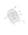
図1,図2は、本発明の実施形態に係る腕ホルダー100の斜視図である。本実施形態では、腕ホルダー100は、例えば人工透析治療を受ける患者の腕を固定するために使用される。同図が示す通り、腕ホルダー100は、本体110と金属製枠体170とを有する。本実施形態の特徴とするところは、本体110はステンレス鋼から構成され、同図が示すようなメッシュ構造を備えて略筒状に湾曲形成されている点、金属製枠体170が本体110の周囲に配置されている点、及び本体110,金属製枠体170に耐薬性コーティングが施されている点である。 1 and 2 are perspective views of an
[本体110][Main body 110]
本体110は、メッシュ構造のステンレス鋼板からなる。本体110は、後端縁140から先端縁130に向かって漸次横幅が短くなるような略台形形状の平板からなる。本実施形態では、本体110の裁断寸法は長手方向寸法が約34cmであり、短手方向寸法が最大で約21cm、最小で約18cmである。この本体110は側縁121,122が互いに近接するように湾曲されており、後端縁140及び先端縁130と側縁121,122とは曲線状に連続している。 The
本体110は多数の菱形の孔を有する。菱形の2つの対角線の長さはそれぞれ約5mmと約1cmである。当該菱形の孔を区画し、かつメッシュを構成する枠の太さは、約1.5mmである。もっとも、上述の孔の形状は一例に過ぎず、通気性等の観点から当業者が最適な形状を選択することができる。本体110の横幅寸法は、後端縁140から先端縁130に向かって漸次短くなっているため、本体110の外径は、その後端側から先端側に向かって漸次小さくなる。 The
[金属製枠体170][Metal frame 170]
図4は、図3における要部拡大図であって、本体110の側縁121の構造を詳細に示している。図1ないし図4が示すように本体110の周縁を巻回するように金属製枠体170が配置されている。金属製枠体170は、ステンレス鋼の板が帯状に切断されたものであり、その幅寸法は約5mmである。図3が示すように金属製枠体170は、本体110の内側から本体110の周縁に沿って溶接されている。本体110の先端縁130及び後端縁140に溶接された金属製枠体170は、本体110と共に湾曲されている。湾曲された金属製枠体170は、弾性をもって本体110の湾曲形状を維持する。従って、仮に側縁121,122同士が弾性的に離反されて本体110が展開されたとしても、本体110は元の状態に復帰することができる。 FIG. 4 is an enlarged view of a main part in FIG. 3 and shows the structure of the
[アンカー部材180,190][
図5は、本発明の実施形態に係る腕ホルダー100の正面図である。図1,図2,図5が示すように本体110の側縁121,122に沿って、それぞれアンカー部材180,190が設けられている。アンカー部材180,190は、それぞれステンレス鋼から成り、側縁121,122の近傍に溶接されている。アンカー部材180には、4つのガイド部181,182,183,184が並設されている。同様に、アンカー部材190には、4つのガイド部191,192,193,194が並設されている。ガイド部181,182,183,184,191,192,193,194は、それぞれ本体110から外側に張り出すように屈曲されており、本体110とガイド部181,182,183,184,191,192,193,194との間には7mm程度の隙間が形成されている。したがって、本体110とガイド部181,182,183,184,191,192,193,194とによってループが形成されている。このループは、後述されるベルト400が、本体110に囲繞された状態を保持するものである。ここで、ガイド部181,182,183,184,191,192,193,194がそれぞれ本発明におけるベルトアンカーに相当するものである。 FIG. 5 is a front view of the
[ライナー211][Liner 211]
図3,4が示す通り、本体110の側縁121,122に沿って、外側からライナー211がそれぞれ溶接されている。ライナー211は、金属製枠体170と同じくステンレス鋼の板が帯状に切断されたものである。即ち、本体110の側縁121,122は、本体110が金属製枠体170とライナー211とにより、裏表両側から挟みこまれた3重の構造になっている。当該3重の構造により、側縁121,122の曲げ剛性が向上されている。 3 and 4, the
[リング151,152,153,154][
図1,図2が示す通り、本実施形態に於いて、本体110には、先端縁130及び後端縁140周辺にそれぞれ2つずつ、ステンレス鋼で形成されたリング151,152,153,154が設けられている。リング151,152,153,154は、腕ホルダー100を支持するための固定部材と係合するためのものである。この固定部材とは、例えば図示されていない所定の固定台から延びたロープであって、その先端にリング状のジョイントが設けられていてもよい。リング151,152,153,154を介して腕ホルダー100が当該固定部材により支持されることで、透析中に、患者が意図的に、あるいは意図せずに腕を動かした際も、腕ホルダー100が透析用の固定台から落下することは回避される。ここで、リング151,152,153,154が、それぞれ本発明における固定具に相当するものである。 As shown in FIGS. 1 and 2, in this embodiment, the
[目印160][Indicator 160]
図1,図2が示す通り、本実施形態に於いて、本体110の先端縁130付近には、先端側を示す目印160が溶接されている。目印160は、ステンレス鋼から形成された円盤である。目印160により、医師や看護師は本体110の先端側と後端側を即座に判断することができる。 As shown in FIGS. 1 and 2, in the present embodiment, a
図3,4が示す通り、本実施形態に係る腕ホルダー100には、ポリエチレンコーティングが施され、各構成部材の外側をポリエチレン層220が覆っている。ポリエチレンは化学的に安定しており、強酸化性酸以外の酸、アルカリ、無機塩類溶液に対して優れた抵抗性を発揮することが知られている。ポリエチレンコーティングは、一般に耐薬性のコーティングとして使用される。ポリエチレンコーティングにより、腕ホルダー100は、ステンレス素材に化学的な変化を起こすことなく、例えばステリハイド、塩化ベンザルコニウム、イソプロピルアルコール、次亜塩素酸ナトリウム等の薬品により洗浄されることができる。 As shown in FIGS. 3 and 4, the
[ベルト400][Belt 400]
図6は、本発明の実施形態に係る腕ホルダー100とベルト400の斜視図である。同図が示す通り、ベルト400は、ゴム製のベルト本体410と、フック440とを有する。フック440はステンレス鋼からなり、前述のガイド部181,182,183,184,191,192,193,194と係合することができる。ベルト本体410の後端付近の片面は、面ファスナーにおけるループ面420として形成されている。そして、ベルト本体410の反対側の面は、ループ面420と接着可能なフック面430として形成されている。 FIG. 6 is a perspective view of the
図7は、本発明の実施形態に係る腕ホルダー100により、腕510が固定された状態を示す斜視図である。例えば人工透析治療に於いて、腕ホルダー100により、患者の腕が固定される手順が以下に解説される。医師又は看護師(以下、「作業者」という。)は、本体110を一旦弾性的に展開した状態で患者の腕を本体110内に配置する。その際、患者の腕は、手首が先端縁140側に位置する方向に配置される。その後に本体110の弾性変形が復元されることにより、腕ホルダー100が腕に沿って巻き付くように装着される。腕に腕ホルダー100が装着された後、作業者は患者の腕に透析用の針を刺す。 FIG. 7 is a perspective view showing a state where the
続けて、作業者は、アンカー部材180に設けられたガイド部182にベルト400のフック440を係合させる。そして、作業者は、ベルト本体410を、本体110の上方から反対側の側縁に渡して対向するガイド部192のループに通す。作業者は、ベルト本体410を本体110の下方に回して本体110を囲繞する。作業者は、ベルト本体410を周方向に引っ張り、適度な締め付けを行った後、ループ面420をフック面430に押圧し、接着させる。このときにループ面420を接着させる位置により、本体110の締め付けの度合いが調整される。ベルト400の締め付けが本体110の形状を変化させ、側縁121,122がさらに近接する方向に湾曲し、本体110は腕を固定する。各ガイド部がベルト400の移動を阻害し、ベルト400の位置決めを行うため、腕ホルダー100からベルト400が抜け落ちることは防止される。 Subsequently, the operator engages the
同図が示す通り、腕510の内側が本体110の側縁121,122の間から露出し、図には示されない目印160が腕510の手首側に来るように本体110が配置されている。本実施形態では、ベルト400が側縁121,122にそれぞれ4つ並設されたガイド部181,182,183,184,191,192,193,194に任意に係合することにより、本体110が腕に締結される。ベルト400がいずれのガイド部に契合されるかは、作業者が状況に応じて判断することができる。 As shown in the figure, the
[本実施形態の効果][Effect of this embodiment]
人工透析中の患者の腕に腕ホルダー100が装着された場合は、治療中に患者が腕を曲げることを防止することができるので、抜針事故の発生を抑制することができる。また、腕ホルダー100はメッシュ構造のため、通気性が良く、発汗による不快感を誘発しない。また通水性に優れるので、人工透析中に水分センサーが併用されることにより、抜針等による出血が当該センサーにより迅速に検知される。 When the
腕ホルダー100は、例えば人工透析治療を受ける患者の腕に巻き付くように装着され、
ベルト400により締結される。これにより、湾曲された形状が弾性的に維持されるので、患者の腕は確実に固定される。The
Fastened by
腕ホルダー100は金属から構成されるので、腕を真っ直ぐな状態に確実に保持することができると共に汚れが付着しにくく衛生的である。さらに、耐薬性コーティングが施されているから、薬品による化学反応が起こりにくく除菌、殺菌処理が容易に行われる。 Since the
腕ホルダー100にはポリエチレンコーティングが施されている。ポリエチレンは吸水率が低いため、ポリエチレン層220に浸透した薬品が腕ホルダー100を構成するステンレス鋼を腐食させることはない。また、ステンレス鋼自体の耐食性が高いため、仮にポリエチレンコーティングが剥離されたとしても、腕ホルダー100を構成するステンレス鋼は腐食を起こしにくい。 The
本体110の側縁121,122が金属製枠体170とライナー211とにより挟み込まれた3重の構造を有するので、側縁121,122の断面係数は大きくなり、側縁121,122の曲げ剛性が向上する。それにより、腕ホルダー100に曲げモーメント等の外力が加えられた際に側縁に生じる応力は小さくなる。すなわち、患者が無意識に腕を曲げようとした場合でも、患者の腕は確実に固定され、抜針事故が防止できる。 Since the side edges 121 and 122 of the
腕ホルダー100は4つのリング151,152,153,154を介して固定台に支持されるため、透析中に腕ホルダー100が台から落下することは防止される。 Since the
人の腕は腕の付け根から手首に向かって細くなっている。本体110の外径は、後端側から先端側に向かって漸次小さくなっているため、上記腕が固定される際に、本体110の先端側が手首に近い側に配置されることで、本体と腕との間には余分な隙間が介在されず、患者の腕は確実に固定される。 A person's arm is narrowed from the base of the arm toward the wrist. Since the outer diameter of the
目印160が腕ホルダー100の先端側に設けられているので、医師または看護師は、どちらの端部に目印160があるかを確認することで、腕ホルダー100の先端側と後端側とを即座に判断することができる。 Since the
アンカー部材180,190により、ベルト400は本体110の側面を囲繞した状態に保持される。アンカー部材180,190がベルト400の横ずれすなわち長手方向の移動を阻害し、ベルト400の位置決めを行うため、腕ホルダー100からベルト400が抜け落ちることが防止される。また、アンカー部材180,190に並設された複数のガイド部181,182,183,184,191,192,193,194のいずれにもベルト400が使用され得るので、患者の腕は確実に固定される。 The
[変形例][Modification]
以下、上述の実施形態の変形例が説明される。図8は、本変形例に係る腕ホルダー600の正面図である。同図が示す通り、上述の実施形態に係る腕ホルダー100と本変形例に係る腕ホルダー600とは、アンカー部材の形状が異なる。本変形例によると、アンカー部材610は、ガイド部611,612,613,614を備える。同様に、アンカー部材620は、ガイド部621,622,623,624を備える。 Hereinafter, modifications of the above-described embodiment will be described. FIG. 8 is a front view of an
[アンカー部材610,620][Anchor members 610, 620]
アンカー部材610のガイド部611は、係合棒611cと、係合棒611cの両側に設けられて係合棒611cよりも隆起した肩部611a,611bとを有する。ここで、係合棒611cの長さは、ベルト400におけるフック440及びベルト本体410の横幅よりも数ミリ程度広くなっている。アンカー部材610,620の全てのガイド部611,612,613,614,711,712,713,714が同様の構成になっている。 The
ベルト400による本体110の締結の手順が以下に解説される。例えば、作業者がガイド部611の係合棒611cにフック440を係合させ、ベルト本体410に本体110を囲繞させる点は上述の実施形態と同様である。ただし、本変形例に於いては、ベルト400が係合棒611cに巻かれた状態で、係合棒611cの両端に延設された肩部611a,611bはベルト400の外側に当接する。 The procedure for fastening the
[本変形例の効果][Effect of this modification]
ベルト400は係合棒611cの外側を囲繞するように本体110に巻かれる。係合棒611の両端に延設された肩部611a,611bはベルトの外側に当接するため、ベルト400は係合棒611cに位置決めされる。従って、腕ホルダー600からベルト400が抜け落ちることが確実に防止される。ベルト400は係合棒611cの外側に巻かれるため、ベルト400をガイド部611に通す手順は省略され、ベルト400の締結に要する時間は短縮される。 The
100・・・腕ホルダー
110・・・本体
121・・・側縁
122・・・側縁
130・・・先端縁
140・・・後端縁
151・・・リング
152・・・リング
153・・・リング
154・・・リング
160・・・目印
170・・・金属製枠体
180・・・アンカー部材
181・・・ガイド部
182・・・ガイド部
183・・・ガイド部
184・・・ガイド部
190・・・アンカー部材
191・・・ガイド部
192・・・ガイド部
193・・・ガイド部
194・・・ガイド部
211・・・ライナー
220・・・ポリエチレン層
400・・・ベルト
410・・・ベルト本体
420・・・ループ面
430・・・フック面
440・・・フック
510・・・腕
600・・・腕ホルダー
610・・・アンカー部材
611・・・ガイド部
611a・・・肩部
611b・・・肩部
611c・・・係合棒
612・・・ガイド部
613・・・ガイド部
614・・・ガイド部
620・・・アンカー部材
621・・・ガイド部
622・・・ガイド部
623・・・ガイド部
624・・・ガイド部
DESCRIPTION OF
Claims (10)
Translated fromJapanese上記一対の側縁、先端縁及び後端縁に設けられ、上記本体の周縁を巻回するように配置された金属製枠体とを備え、
上記本体及び金属製枠体には、耐薬性コーティングがなされている腕ホルダー。It consists of a metal plate having a mesh structure having a pair of side edges and a front edge and a rear edge that are continuous between the front and rear ends of the pair of side edges, and is curved so that the pair of side edges are close to each other. The main body,
A metal frame provided on the pair of side edges, the leading edge and the trailing edge, and arranged to wind the periphery of the main body,
Arm holder with chemical-resistant coating on the main body and metal frame.
上記固定具は、金属製のリングからなる請求項4に記載の腕ホルダー。A plurality of the fixtures are provided at the front end and the rear end of the main body,
The arm holder according to claim 4, wherein the fixture is made of a metal ring.
当該肩部は、上記係合棒に係合しかつ上記本体に巻回されたベルトを当該係合棒に位置決めするように、当該係合棒に対して隆起している請求項8に記載の腕ホルダー。The belt anchor has an engagement rod extending along the side edge, and shoulders extending at both ends of the engagement rod,
9. The shoulder according to claim 8, wherein the shoulder is raised with respect to the engagement rod so as to position the belt wound around the body and wound around the main body on the engagement rod. Arm holder.
Priority Applications (1)
| Application Number | Priority Date | Filing Date | Title |
|---|---|---|---|
| JP2010128439AJP5033222B2 (en) | 2010-06-04 | 2010-06-04 | Arm holder |
Applications Claiming Priority (1)
| Application Number | Priority Date | Filing Date | Title |
|---|---|---|---|
| JP2010128439AJP5033222B2 (en) | 2010-06-04 | 2010-06-04 | Arm holder |
Publications (2)
| Publication Number | Publication Date |
|---|---|
| JP2010214132Atrue JP2010214132A (en) | 2010-09-30 |
| JP5033222B2 JP5033222B2 (en) | 2012-09-26 |
Family
ID=42973578
Family Applications (1)
| Application Number | Title | Priority Date | Filing Date |
|---|---|---|---|
| JP2010128439AActiveJP5033222B2 (en) | 2010-06-04 | 2010-06-04 | Arm holder |
Country Status (1)
| Country | Link |
|---|---|
| JP (1) | JP5033222B2 (en) |
Cited By (49)
| Publication number | Priority date | Publication date | Assignee | Title |
|---|---|---|---|---|
| JP2013123643A (en)* | 2011-12-14 | 2013-06-24 | Covidien Lp | Surgical stapling device including attachment of buttress via tab |
| US9861733B2 (en) | 2012-03-23 | 2018-01-09 | Nxstage Medical Inc. | Peritoneal dialysis systems, devices, and methods |
| US9907897B2 (en) | 2011-03-23 | 2018-03-06 | Nxstage Medical, Inc. | Peritoneal dialysis systems, devices, and methods |
| US10576298B2 (en) | 2009-10-15 | 2020-03-03 | Covidien Lp | Buttress brachytherapy and integrated staple line markers for margin identification |
| US10722234B2 (en) | 2013-02-28 | 2020-07-28 | Covidien Lp | Adherence concepts for non-woven absorbable felt buttresses |
| US10758237B2 (en) | 2018-04-30 | 2020-09-01 | Covidien Lp | Circular stapling apparatus with pinned buttress |
| US10806459B2 (en) | 2018-09-14 | 2020-10-20 | Covidien Lp | Drug patterned reinforcement material for circular anastomosis |
| US10813636B2 (en) | 2004-10-18 | 2020-10-27 | Covidien Lp | Annular adhesive structure |
| US10828034B2 (en) | 2011-12-14 | 2020-11-10 | Covidien Lp | Buttress attachment to the cartridge surface |
| US10849625B2 (en) | 2017-08-07 | 2020-12-01 | Covidien Lp | Surgical buttress retention systems for surgical stapling apparatus |
| US10874768B2 (en) | 2017-01-20 | 2020-12-29 | Covidien Lp | Drug eluting medical device |
| US10881395B2 (en) | 2012-08-20 | 2021-01-05 | Covidien Lp | Buttress attachment features for surgical stapling apparatus |
| US10925607B2 (en) | 2017-02-28 | 2021-02-23 | Covidien Lp | Surgical stapling apparatus with staple sheath |
| US10945733B2 (en) | 2017-08-23 | 2021-03-16 | Covidien Lp | Surgical buttress reload and tip attachment assemblies for surgical stapling apparatus |
| US10952729B2 (en) | 2018-10-03 | 2021-03-23 | Covidien Lp | Universal linear buttress retention/release assemblies and methods |
| US11045200B2 (en) | 2004-10-18 | 2021-06-29 | Covidien Lp | Support structures and methods of using the same |
| US11065000B2 (en) | 2018-02-22 | 2021-07-20 | Covidien Lp | Surgical buttresses for surgical stapling apparatus |
| US11096610B2 (en) | 2017-03-28 | 2021-08-24 | Covidien Lp | Surgical implants including sensing fibers |
| US11141151B2 (en) | 2017-12-08 | 2021-10-12 | Covidien Lp | Surgical buttress for circular stapling |
| US11207454B2 (en) | 2018-02-28 | 2021-12-28 | Nxstage Medical, Inc. | Fluid preparation and treatment devices methods and systems |
| US11219460B2 (en) | 2018-07-02 | 2022-01-11 | Covidien Lp | Surgical stapling apparatus with anvil buttress |
| US11284896B2 (en) | 2018-05-09 | 2022-03-29 | Covidien Lp | Surgical buttress loading and attaching/detaching assemblies |
| US11337699B2 (en) | 2020-04-28 | 2022-05-24 | Covidien Lp | Magnesium infused surgical buttress for surgical stapler |
| US11399833B2 (en) | 2020-10-19 | 2022-08-02 | Covidien Lp | Anvil buttress attachment for surgical stapling apparatus |
| US11419609B2 (en) | 2012-01-26 | 2022-08-23 | Covidien Lp | Surgical device including buttress material |
| US11419608B2 (en) | 2007-06-18 | 2022-08-23 | Covidien Lp | Interlocking buttress material retention system |
| US11426163B2 (en) | 2018-05-09 | 2022-08-30 | Covidien Lp | Universal linear surgical stapling buttress |
| US11432818B2 (en) | 2018-05-09 | 2022-09-06 | Covidien Lp | Surgical buttress assemblies |
| US11478245B2 (en) | 2019-05-08 | 2022-10-25 | Covidien Lp | Surgical stapling device |
| US11510670B1 (en) | 2021-06-23 | 2022-11-29 | Covidien Lp | Buttress attachment for surgical stapling apparatus |
| US11523824B2 (en) | 2019-12-12 | 2022-12-13 | Covidien Lp | Anvil buttress loading for a surgical stapling apparatus |
| US11534170B2 (en) | 2021-01-04 | 2022-12-27 | Covidien Lp | Anvil buttress attachment for surgical stapling apparatus |
| US11547407B2 (en) | 2020-03-19 | 2023-01-10 | Covidien Lp | Staple line reinforcement for surgical stapling apparatus |
| US11571208B2 (en) | 2019-10-11 | 2023-02-07 | Covidien Lp | Surgical buttress loading units |
| US11596399B2 (en) | 2021-06-23 | 2023-03-07 | Covidien Lp | Anvil buttress attachment for surgical stapling apparatus |
| US11596403B2 (en) | 2019-05-08 | 2023-03-07 | Covidien Lp | Surgical stapling device |
| US11666334B2 (en) | 2009-03-31 | 2023-06-06 | Covidien Lp | Surgical stapling apparatus |
| US11672538B2 (en) | 2021-06-24 | 2023-06-13 | Covidien Lp | Surgical stapling device including a buttress retention assembly |
| US11678879B2 (en) | 2021-07-01 | 2023-06-20 | Covidien Lp | Buttress attachment for surgical stapling apparatus |
| US11684368B2 (en) | 2021-07-14 | 2023-06-27 | Covidien Lp | Surgical stapling device including a buttress retention assembly |
| US11707276B2 (en) | 2020-09-08 | 2023-07-25 | Covidien Lp | Surgical buttress assemblies and techniques for surgical stapling |
| US11730472B2 (en) | 2019-04-25 | 2023-08-22 | Covidien Lp | Surgical system and surgical loading units thereof |
| US11751875B2 (en) | 2021-10-13 | 2023-09-12 | Coviden Lp | Surgical buttress attachment assemblies for surgical stapling apparatus |
| US11801052B2 (en) | 2021-08-30 | 2023-10-31 | Covidien Lp | Assemblies for surgical stapling instruments |
| US11806017B2 (en) | 2021-11-23 | 2023-11-07 | Covidien Lp | Anvil buttress loading system for surgical stapling apparatus |
| US11969169B2 (en) | 2019-09-10 | 2024-04-30 | Covidien Lp | Anvil buttress loading unit for a surgical stapling apparatus |
| US12048791B2 (en) | 2017-06-24 | 2024-07-30 | Nxstage Medical, Inc. | Peritoneal dialysis fluid preparation and/or treatment devices methods and systems |
| US12070213B2 (en) | 2022-02-24 | 2024-08-27 | Covidien Lp | Surgical medical devices |
| US12076013B2 (en) | 2021-08-03 | 2024-09-03 | Covidien Lp | Surgical buttress attachment assemblies for surgical stapling apparatus |
- 2010
- 2010-06-04JPJP2010128439Apatent/JP5033222B2/enactiveActive
Cited By (82)
| Publication number | Priority date | Publication date | Assignee | Title |
|---|---|---|---|---|
| US11045200B2 (en) | 2004-10-18 | 2021-06-29 | Covidien Lp | Support structures and methods of using the same |
| US10813636B2 (en) | 2004-10-18 | 2020-10-27 | Covidien Lp | Annular adhesive structure |
| US11419608B2 (en) | 2007-06-18 | 2022-08-23 | Covidien Lp | Interlocking buttress material retention system |
| US11666334B2 (en) | 2009-03-31 | 2023-06-06 | Covidien Lp | Surgical stapling apparatus |
| US12201297B2 (en) | 2009-03-31 | 2025-01-21 | Covidien Lp | Surgical stapling apparatus |
| US10576298B2 (en) | 2009-10-15 | 2020-03-03 | Covidien Lp | Buttress brachytherapy and integrated staple line markers for margin identification |
| US10603424B2 (en) | 2011-03-23 | 2020-03-31 | Nxstage Medical, Inc. | Peritoneal dialysis systems, devices, and methods |
| US9907897B2 (en) | 2011-03-23 | 2018-03-06 | Nxstage Medical, Inc. | Peritoneal dialysis systems, devices, and methods |
| US10688234B2 (en) | 2011-03-23 | 2020-06-23 | Nxstage Medical, Inc. | Peritoneal dialysis systems, devices, and methods |
| US10688235B2 (en) | 2011-03-23 | 2020-06-23 | Nxstage Medical, Inc. | Peritoneal dialysis systems, devices, and methods |
| US11690941B2 (en) | 2011-03-23 | 2023-07-04 | Nxstage Medical, Inc. | Peritoneal dialysis systems, devices, and methods |
| US12246121B2 (en) | 2011-03-23 | 2025-03-11 | Nxstage Medical, Inc. | Peritoneal dialysis systems, devices, and methods |
| US11717601B2 (en) | 2011-03-23 | 2023-08-08 | Nxstage Medical, Inc. | Dialysis systems, devices, and methods |
| US10046100B2 (en) | 2011-03-23 | 2018-08-14 | Nxstage Medical, Inc. | Peritoneal dialysis systems, devices, and methods |
| US10610630B2 (en) | 2011-03-23 | 2020-04-07 | Nxstage Medical, Inc. | Peritoneal dialysis systems, devices, and methods |
| US11224684B2 (en) | 2011-03-23 | 2022-01-18 | Nxstage Medical, Inc. | Peritoneal dialysis systems, devices, and methods |
| US11433169B2 (en) | 2011-03-23 | 2022-09-06 | Nxstage Medical, Inc. | Dialysis systems, devices, and methods |
| US11135348B2 (en) | 2011-03-23 | 2021-10-05 | Nxstage Medical, Inc. | Peritoneal dialysis systems, devices, and methods |
| US10898630B2 (en) | 2011-03-23 | 2021-01-26 | Nxstage Medical, Inc. | Peritoneal dialysis systems, devices, and methods |
| US11433170B2 (en) | 2011-03-23 | 2022-09-06 | Nxstage Medical, Inc. | Dialysis systems, devices, and methods |
| JP2013123643A (en)* | 2011-12-14 | 2013-06-24 | Covidien Lp | Surgical stapling device including attachment of buttress via tab |
| US10828034B2 (en) | 2011-12-14 | 2020-11-10 | Covidien Lp | Buttress attachment to the cartridge surface |
| US10321908B2 (en) | 2011-12-14 | 2019-06-18 | Covidien Lp | Surgical stapling apparatus including buttress attachment via tabs |
| US11419609B2 (en) | 2012-01-26 | 2022-08-23 | Covidien Lp | Surgical device including buttress material |
| US9861733B2 (en) | 2012-03-23 | 2018-01-09 | Nxstage Medical Inc. | Peritoneal dialysis systems, devices, and methods |
| US10881395B2 (en) | 2012-08-20 | 2021-01-05 | Covidien Lp | Buttress attachment features for surgical stapling apparatus |
| US10722234B2 (en) | 2013-02-28 | 2020-07-28 | Covidien Lp | Adherence concepts for non-woven absorbable felt buttresses |
| US10874768B2 (en) | 2017-01-20 | 2020-12-29 | Covidien Lp | Drug eluting medical device |
| US11571498B2 (en) | 2017-01-20 | 2023-02-07 | Covidien Lp | Drug eluting medical device |
| US10925607B2 (en) | 2017-02-28 | 2021-02-23 | Covidien Lp | Surgical stapling apparatus with staple sheath |
| US11096610B2 (en) | 2017-03-28 | 2021-08-24 | Covidien Lp | Surgical implants including sensing fibers |
| US12048791B2 (en) | 2017-06-24 | 2024-07-30 | Nxstage Medical, Inc. | Peritoneal dialysis fluid preparation and/or treatment devices methods and systems |
| US11426164B2 (en) | 2017-08-07 | 2022-08-30 | Covidien Lp | Surgical buttress retention systems for surgical stapling apparatus |
| US10849625B2 (en) | 2017-08-07 | 2020-12-01 | Covidien Lp | Surgical buttress retention systems for surgical stapling apparatus |
| US10945733B2 (en) | 2017-08-23 | 2021-03-16 | Covidien Lp | Surgical buttress reload and tip attachment assemblies for surgical stapling apparatus |
| US11446033B2 (en) | 2017-08-23 | 2022-09-20 | Covidien Lp | Surgical buttress reload and tip attachment assemblies for surgical stapling apparatus |
| US11801053B2 (en) | 2017-08-23 | 2023-10-31 | Covidien Lp | Surgical buttress reload and tip attachment assemblies for surgical stapling apparatus |
| US11653916B2 (en) | 2017-12-08 | 2023-05-23 | Covidien Lp | Surgical buttress for circular stapling |
| US11141151B2 (en) | 2017-12-08 | 2021-10-12 | Covidien Lp | Surgical buttress for circular stapling |
| US11065000B2 (en) | 2018-02-22 | 2021-07-20 | Covidien Lp | Surgical buttresses for surgical stapling apparatus |
| US11872337B2 (en) | 2018-02-28 | 2024-01-16 | Nxstage Medical, Inc. | Fluid preparation and treatment devices methods and systems |
| US11207454B2 (en) | 2018-02-28 | 2021-12-28 | Nxstage Medical, Inc. | Fluid preparation and treatment devices methods and systems |
| US11364328B2 (en) | 2018-02-28 | 2022-06-21 | Nxstage Medical, Inc. | Fluid preparation and treatment devices methods and systems |
| US12409259B2 (en) | 2018-02-28 | 2025-09-09 | Nxstage Medical, Inc. | Fluid preparation and treatment devices methods and systems |
| US11350940B2 (en) | 2018-04-30 | 2022-06-07 | Covidien Lp | Circular stapling apparatus with pinned buttress |
| US10758237B2 (en) | 2018-04-30 | 2020-09-01 | Covidien Lp | Circular stapling apparatus with pinned buttress |
| US11432818B2 (en) | 2018-05-09 | 2022-09-06 | Covidien Lp | Surgical buttress assemblies |
| US11284896B2 (en) | 2018-05-09 | 2022-03-29 | Covidien Lp | Surgical buttress loading and attaching/detaching assemblies |
| US11426163B2 (en) | 2018-05-09 | 2022-08-30 | Covidien Lp | Universal linear surgical stapling buttress |
| US11931039B2 (en) | 2018-05-09 | 2024-03-19 | Covidien Lp | Surgical buttress loading and attaching/detaching assemblies |
| US11219460B2 (en) | 2018-07-02 | 2022-01-11 | Covidien Lp | Surgical stapling apparatus with anvil buttress |
| US11376008B2 (en) | 2018-09-14 | 2022-07-05 | Covidien Lp | Drug patterned reinforcement material for circular anastomosis |
| US10806459B2 (en) | 2018-09-14 | 2020-10-20 | Covidien Lp | Drug patterned reinforcement material for circular anastomosis |
| US10952729B2 (en) | 2018-10-03 | 2021-03-23 | Covidien Lp | Universal linear buttress retention/release assemblies and methods |
| US11627964B2 (en) | 2018-10-03 | 2023-04-18 | Covidien Lp | Universal linear buttress retention/release assemblies and methods |
| US11730472B2 (en) | 2019-04-25 | 2023-08-22 | Covidien Lp | Surgical system and surgical loading units thereof |
| US11596403B2 (en) | 2019-05-08 | 2023-03-07 | Covidien Lp | Surgical stapling device |
| US11478245B2 (en) | 2019-05-08 | 2022-10-25 | Covidien Lp | Surgical stapling device |
| US11969169B2 (en) | 2019-09-10 | 2024-04-30 | Covidien Lp | Anvil buttress loading unit for a surgical stapling apparatus |
| US11571208B2 (en) | 2019-10-11 | 2023-02-07 | Covidien Lp | Surgical buttress loading units |
| US11523824B2 (en) | 2019-12-12 | 2022-12-13 | Covidien Lp | Anvil buttress loading for a surgical stapling apparatus |
| US12376854B2 (en) | 2019-12-12 | 2025-08-05 | Covidien Lp | Anvil buttress loading for a surgical stapling apparatus |
| US11547407B2 (en) | 2020-03-19 | 2023-01-10 | Covidien Lp | Staple line reinforcement for surgical stapling apparatus |
| US11337699B2 (en) | 2020-04-28 | 2022-05-24 | Covidien Lp | Magnesium infused surgical buttress for surgical stapler |
| US11707276B2 (en) | 2020-09-08 | 2023-07-25 | Covidien Lp | Surgical buttress assemblies and techniques for surgical stapling |
| US11957348B2 (en) | 2020-10-19 | 2024-04-16 | Covidien Lp | Anvil buttress attachment for surgical stapling apparatus |
| US11399833B2 (en) | 2020-10-19 | 2022-08-02 | Covidien Lp | Anvil buttress attachment for surgical stapling apparatus |
| US11534170B2 (en) | 2021-01-04 | 2022-12-27 | Covidien Lp | Anvil buttress attachment for surgical stapling apparatus |
| US12004746B2 (en) | 2021-01-04 | 2024-06-11 | Covidien Lp | Anvil buttress attachment for surgical stapling apparatus |
| US12127740B2 (en) | 2021-06-23 | 2024-10-29 | Covidien Lp | Buttress attachment for surgical stapling apparatus |
| US11596399B2 (en) | 2021-06-23 | 2023-03-07 | Covidien Lp | Anvil buttress attachment for surgical stapling apparatus |
| US11510670B1 (en) | 2021-06-23 | 2022-11-29 | Covidien Lp | Buttress attachment for surgical stapling apparatus |
| US11672538B2 (en) | 2021-06-24 | 2023-06-13 | Covidien Lp | Surgical stapling device including a buttress retention assembly |
| US12102322B2 (en) | 2021-07-01 | 2024-10-01 | Covidien Lp | Buttress attachment for surgical stapling apparatus |
| US11678879B2 (en) | 2021-07-01 | 2023-06-20 | Covidien Lp | Buttress attachment for surgical stapling apparatus |
| US11684368B2 (en) | 2021-07-14 | 2023-06-27 | Covidien Lp | Surgical stapling device including a buttress retention assembly |
| US12076013B2 (en) | 2021-08-03 | 2024-09-03 | Covidien Lp | Surgical buttress attachment assemblies for surgical stapling apparatus |
| US11801052B2 (en) | 2021-08-30 | 2023-10-31 | Covidien Lp | Assemblies for surgical stapling instruments |
| US11751875B2 (en) | 2021-10-13 | 2023-09-12 | Coviden Lp | Surgical buttress attachment assemblies for surgical stapling apparatus |
| US11806017B2 (en) | 2021-11-23 | 2023-11-07 | Covidien Lp | Anvil buttress loading system for surgical stapling apparatus |
| US12137908B2 (en) | 2021-11-23 | 2024-11-12 | Covidien Lp | Anvil buttress loading system for surgical stapling apparatus |
| US12070213B2 (en) | 2022-02-24 | 2024-08-27 | Covidien Lp | Surgical medical devices |
Also Published As
| Publication number | Publication date |
|---|---|
| JP5033222B2 (en) | 2012-09-26 |
Similar Documents
| Publication | Publication Date | Title |
|---|---|---|
| JP5033222B2 (en) | Arm holder | |
| US20090299294A1 (en) | Support devices for catheters | |
| US20110021997A1 (en) | Catheter securement device | |
| JP5092105B2 (en) | Catheter fixture and pad for catheter fixture | |
| US20220249807A1 (en) | Medical dressing for securing a tubiform component of a medical device | |
| EP3654853A1 (en) | Medical compression device | |
| US10022056B2 (en) | Blood pressure measurement cuff and attachment method for the same | |
| KR20190106003A (en) | Apparatus for Fixing a Wrist for Arteriopuncture | |
| KR20190000856U (en) | Medical band | |
| JP2007296082A (en) | Coming-off preventing device for infusion needle | |
| CN204971774U (en) | About band is having arterial[blood] pressure of wound monitoring fixing device | |
| JP5148370B2 (en) | Stethoscope holder | |
| JP6709468B2 (en) | patch | |
| JP2006051091A (en) | Patient protection sheet | |
| US20160114134A1 (en) | Medical Adhesive Tape for Infusion Tubing | |
| CN211270713U (en) | A brachial artery protection and restraint device | |
| JP3198441U (en) | Tube fixing sheet | |
| JP3152902U (en) | Drip needle removal prevention device | |
| CN119033370A (en) | Patch system and patch using method | |
| CN212914045U (en) | Fixing support for internal arteriovenous fistula | |
| CN221578661U (en) | Radial artery puncture hand pad matched with hand supporting plate of operating table | |
| CN222708391U (en) | A sleeve-type sterile surgical sheet for interventional surgery | |
| CN215192761U (en) | Fixing device convenient to be fixed on operative limb after internal arteriovenous fistula operation | |
| CN215189561U (en) | Anti-epidemic protective clothing for children | |
| JP2009011623A (en) | Treated area protector |
Legal Events
| Date | Code | Title | Description |
|---|---|---|---|
| A621 | Written request for application examination | Free format text:JAPANESE INTERMEDIATE CODE: A621 Effective date:20100706 | |
| A977 | Report on retrieval | Free format text:JAPANESE INTERMEDIATE CODE: A971007 Effective date:20120608 | |
| TRDD | Decision of grant or rejection written | ||
| A01 | Written decision to grant a patent or to grant a registration (utility model) | Free format text:JAPANESE INTERMEDIATE CODE: A01 Effective date:20120626 | |
| A01 | Written decision to grant a patent or to grant a registration (utility model) | Free format text:JAPANESE INTERMEDIATE CODE: A01 | |
| A61 | First payment of annual fees (during grant procedure) | Free format text:JAPANESE INTERMEDIATE CODE: A61 Effective date:20120629 | |
| R150 | Certificate of patent or registration of utility model | Ref document number:5033222 Country of ref document:JP Free format text:JAPANESE INTERMEDIATE CODE: R150 Free format text:JAPANESE INTERMEDIATE CODE: R150 | |
| FPAY | Renewal fee payment (event date is renewal date of database) | Free format text:PAYMENT UNTIL: 20150706 Year of fee payment:3 | |
| FPAY | Renewal fee payment (event date is renewal date of database) | Free format text:PAYMENT UNTIL: 20150706 Year of fee payment:3 | |
| R250 | Receipt of annual fees | Free format text:JAPANESE INTERMEDIATE CODE: R250 | |
| R250 | Receipt of annual fees | Free format text:JAPANESE INTERMEDIATE CODE: R250 | |
| R250 | Receipt of annual fees | Free format text:JAPANESE INTERMEDIATE CODE: R250 | |
| R250 | Receipt of annual fees | Free format text:JAPANESE INTERMEDIATE CODE: R250 | |
| R250 | Receipt of annual fees | Free format text:JAPANESE INTERMEDIATE CODE: R250 | |
| R250 | Receipt of annual fees | Free format text:JAPANESE INTERMEDIATE CODE: R250 | |
| R250 | Receipt of annual fees | Free format text:JAPANESE INTERMEDIATE CODE: R250 | |
| R250 | Receipt of annual fees | Free format text:JAPANESE INTERMEDIATE CODE: R250 | |
| R250 | Receipt of annual fees | Free format text:JAPANESE INTERMEDIATE CODE: R250 | |
| S531 | Written request for registration of change of domicile | Free format text:JAPANESE INTERMEDIATE CODE: R313531 | |
| R350 | Written notification of registration of transfer | Free format text:JAPANESE INTERMEDIATE CODE: R350 | |
| R250 | Receipt of annual fees | Free format text:JAPANESE INTERMEDIATE CODE: R250 | |
| R250 | Receipt of annual fees | Free format text:JAPANESE INTERMEDIATE CODE: R250 |