JP2010213367A - Energy saving system using ubiquitous sensor and intelligent table tap - Google Patents
Energy saving system using ubiquitous sensor and intelligent table tapDownload PDFInfo
- Publication number
- JP2010213367A JP2010213367AJP2009053284AJP2009053284AJP2010213367AJP 2010213367 AJP2010213367 AJP 2010213367AJP 2009053284 AJP2009053284 AJP 2009053284AJP 2009053284 AJP2009053284 AJP 2009053284AJP 2010213367 AJP2010213367 AJP 2010213367A
- Authority
- JP
- Japan
- Prior art keywords
- power supply
- power
- information
- electric
- indoor
- Prior art date
- Legal status (The legal status is an assumption and is not a legal conclusion. Google has not performed a legal analysis and makes no representation as to the accuracy of the status listed.)
- Pending
Links
Images


Classifications
- Y—GENERAL TAGGING OF NEW TECHNOLOGICAL DEVELOPMENTS; GENERAL TAGGING OF CROSS-SECTIONAL TECHNOLOGIES SPANNING OVER SEVERAL SECTIONS OF THE IPC; TECHNICAL SUBJECTS COVERED BY FORMER USPC CROSS-REFERENCE ART COLLECTIONS [XRACs] AND DIGESTS
- Y02—TECHNOLOGIES OR APPLICATIONS FOR MITIGATION OR ADAPTATION AGAINST CLIMATE CHANGE
- Y02B—CLIMATE CHANGE MITIGATION TECHNOLOGIES RELATED TO BUILDINGS, e.g. HOUSING, HOUSE APPLIANCES OR RELATED END-USER APPLICATIONS
- Y02B70/00—Technologies for an efficient end-user side electric power management and consumption
- Y02B70/30—Systems integrating technologies related to power network operation and communication or information technologies for improving the carbon footprint of the management of residential or tertiary loads, i.e. smart grids as climate change mitigation technology in the buildings sector, including also the last stages of power distribution and the control, monitoring or operating management systems at local level
- Y—GENERAL TAGGING OF NEW TECHNOLOGICAL DEVELOPMENTS; GENERAL TAGGING OF CROSS-SECTIONAL TECHNOLOGIES SPANNING OVER SEVERAL SECTIONS OF THE IPC; TECHNICAL SUBJECTS COVERED BY FORMER USPC CROSS-REFERENCE ART COLLECTIONS [XRACs] AND DIGESTS
- Y02—TECHNOLOGIES OR APPLICATIONS FOR MITIGATION OR ADAPTATION AGAINST CLIMATE CHANGE
- Y02B—CLIMATE CHANGE MITIGATION TECHNOLOGIES RELATED TO BUILDINGS, e.g. HOUSING, HOUSE APPLIANCES OR RELATED END-USER APPLICATIONS
- Y02B90/00—Enabling technologies or technologies with a potential or indirect contribution to GHG emissions mitigation
- Y02B90/20—Smart grids as enabling technology in buildings sector
- Y—GENERAL TAGGING OF NEW TECHNOLOGICAL DEVELOPMENTS; GENERAL TAGGING OF CROSS-SECTIONAL TECHNOLOGIES SPANNING OVER SEVERAL SECTIONS OF THE IPC; TECHNICAL SUBJECTS COVERED BY FORMER USPC CROSS-REFERENCE ART COLLECTIONS [XRACs] AND DIGESTS
- Y04—INFORMATION OR COMMUNICATION TECHNOLOGIES HAVING AN IMPACT ON OTHER TECHNOLOGY AREAS
- Y04S—SYSTEMS INTEGRATING TECHNOLOGIES RELATED TO POWER NETWORK OPERATION, COMMUNICATION OR INFORMATION TECHNOLOGIES FOR IMPROVING THE ELECTRICAL POWER GENERATION, TRANSMISSION, DISTRIBUTION, MANAGEMENT OR USAGE, i.e. SMART GRIDS
- Y04S20/00—Management or operation of end-user stationary applications or the last stages of power distribution; Controlling, monitoring or operating thereof
- Y04S20/20—End-user application control systems
- Y04S20/242—Home appliances
- Y—GENERAL TAGGING OF NEW TECHNOLOGICAL DEVELOPMENTS; GENERAL TAGGING OF CROSS-SECTIONAL TECHNOLOGIES SPANNING OVER SEVERAL SECTIONS OF THE IPC; TECHNICAL SUBJECTS COVERED BY FORMER USPC CROSS-REFERENCE ART COLLECTIONS [XRACs] AND DIGESTS
- Y04—INFORMATION OR COMMUNICATION TECHNOLOGIES HAVING AN IMPACT ON OTHER TECHNOLOGY AREAS
- Y04S—SYSTEMS INTEGRATING TECHNOLOGIES RELATED TO POWER NETWORK OPERATION, COMMUNICATION OR INFORMATION TECHNOLOGIES FOR IMPROVING THE ELECTRICAL POWER GENERATION, TRANSMISSION, DISTRIBUTION, MANAGEMENT OR USAGE, i.e. SMART GRIDS
- Y04S40/00—Systems for electrical power generation, transmission, distribution or end-user application management characterised by the use of communication or information technologies, or communication or information technology specific aspects supporting them
- Y04S40/12—Systems for electrical power generation, transmission, distribution or end-user application management characterised by the use of communication or information technologies, or communication or information technology specific aspects supporting them characterised by data transport means between the monitoring, controlling or managing units and monitored, controlled or operated electrical equipment
- Y04S40/124—Systems for electrical power generation, transmission, distribution or end-user application management characterised by the use of communication or information technologies, or communication or information technology specific aspects supporting them characterised by data transport means between the monitoring, controlling or managing units and monitored, controlled or operated electrical equipment using wired telecommunication networks or data transmission busses
Landscapes
- Supply And Distribution Of Alternating Current (AREA)
- Details Of Connecting Devices For Male And Female Coupling (AREA)
- Remote Monitoring And Control Of Power-Distribution Networks (AREA)
Abstract
Translated fromJapaneseDescription
Translated fromJapanese本発明は,電気機器に電力を供給する電源供給器具を有する電源制御システムであって,例えば,ユビキタスセンサとインテリジェントテーブルタップによる省エネシステムに関する。 The present invention relates to a power supply control system having a power supply device for supplying power to an electrical device, and relates to an energy saving system using, for example, a ubiquitous sensor and an intelligent table tap.
近年,省エネルギーを目的として,家庭用電化製品(家電)等の電気機器における待機時消費電力(待機電力)の削減が望まれている。待機電力とは,電気機器がその本来の効用を発揮していないときに消費する電力のことをいい,例えばテレビ,ビデオデッキ,エアコン等がリモコンによる操作を待ち受けているときに消費する電力等がそれに該当する。家庭の消費エネルギーの約1割を待機電力が占めていることが知られている。 In recent years, for the purpose of energy saving, reduction of standby power consumption (standby power) in electrical appliances such as household appliances (home appliances) has been desired. Standby power refers to the power consumed when an electrical device is not performing its original utility. For example, the power consumed when a TV, VCR, air conditioner, etc. is waiting for an operation by a remote control. That is true. It is known that standby electricity accounts for about 10% of household energy consumption.
従来,電気機器の電源コードのプラグを人の手によってコンセントから抜くことで,待機電力を削減していた。また,電気機器への電力供給を制限するためのスイッチをテーブルタップに設け,このスイッチを人の手によって切り替えることで,待機電力を削減していた。 Conventionally, standby power has been reduced by unplugging the power cords of electrical equipment from the outlet by hand. In addition, standby power is reduced by providing a switch for limiting power supply to the electrical equipment on the table tap and switching the switch manually.
なお,特許文献1には,省エネルギーを目的として,電力等のエネルギーの消費量の実績値を計測し,これを目標値と比較した情報等をエネルギー消費者に提供するシステムが開示されている。 For the purpose of energy saving,
しかしながら,待機電力を削減するために,コンセントに対するプラグの抜き差しや,テーブルタップのスイッチの切り替えを行うのでは,人の手間がかかってしまい,効率がよくない。 However, in order to reduce standby power, plugging and unplugging the outlet and switching the switch of the table tap are time-consuming and inefficient.
そこで,本発明は,人の手を煩わすことなく,電気機器への制御に連動して,効率よく待機電力を削減することができる電源制御システムを提供することを目的とする。 SUMMARY OF THE INVENTION An object of the present invention is to provide a power supply control system that can efficiently reduce standby power in conjunction with control of electric equipment without bothering human hands.
本発明における電源制御システムは,電気機器50A,50Bと,前記電気機器50A,50Bに電力を供給する電源供給器具10と,前記電気機器50A,50B及び前記電源供給器具10に制御信号を送信する制御部21とを備えている。また,前記電源供給器具10は,前記制御信号に基づいて,前記電気機器50A,50Bへの電力供給を停止する。 The power supply control system according to the present invention transmits the control signals to the
この構成により,電源供給器具10が,制御部21から電気機器50A,50Bへ送信される制御信号に連動して,電気機器50A,50Bへの電力供給を停止する。これにより,人の手を煩わすことなく,効率よく待機電力を削減することができる。 With this configuration, the
本発明における電源制御システムにおいて,前記制御部21は,少なくとも前記電気機器50A,50Bの電源をオン又はオフにする信号を前記制御信号として,前記電気機器50A,50B及び前記電源供給器具10に送信する。また,前記電源供給器具10は,前記制御信号が前記電気機器50A,50Bの電源をオフにする信号である場合に,前記電気機器50A,50Bへの電力供給を停止する。 In the power supply control system according to the present invention, the
この構成により,電源供給器具10が,電気機器50A,50Bの電源をオフする制御信号に連動して,電気機器50A,50Bへの電力供給を停止する。これにより,人の手を煩わすことなく,電気機器への制御に連動して,効率よく待機電力を削減することができる。 With this configuration, the
本発明における電源制御システムにおいて,前記電源供給器具10は,前記電気機器50A,50Bに供給した電力を計測する。これにより,電気機器50A,50Bの電力使用量を取得することができる。 In the power supply control system according to the present invention, the
本発明における電源制御システムは,複数の前記電気機器50A,50Bを備えている。また,前記電源供給器具10は,前記電気機器50A,50B毎に,前記電器機器50A,50Bに供給した電力をそれぞれ計測する。これにより,電気機器50A,50B毎に電力使用量を取得することができる。 The power supply control system according to the present invention includes a plurality of the
本発明における電源制御システムは,前記制御部21からの指令を受け,前記指令に基づいた情報を出力するための出力部23を備えている。また,前記制御部21は,前記電源供給器具10により計測された前記電力情報を取得し,取得した前記電力情報に基づいた指令を前記出力部23へ出力する。これにより,電気機器50A,50Bの電力使用量が出力部23に出力される。この結果,エネルギー消費者が,出力部23の出力を確認することで,電気機器50A,50Bの電力使用量を確認することができる。 The power supply control system according to the present invention includes an output unit 23 for receiving a command from the
本発明における電源制御システムは,前記電気機器50A,50Bが配置された部屋,家屋又は建物の屋内に設置され,前記屋内の状態に関する屋内情報を検出する環境センサを備えている。また,前記制御部21は,前記環境センサにより検出された前記屋内情報と,前記電源供給器具10により計測された前記電力情報とに基づいた指令を前記出力部23へ出力する。これにより,電力情報が屋内情報と共に出力部23に出力される。この結果,エネルギー消費者が,出力部23の出力を確認することで,電気機器50A,50Bの電力情報を屋内情報と合わせて得ることができる。 The power supply control system according to the present invention is installed in a room, house, or building in which the
本発明における電源制御システムは,前記制御部21と情報の授受を行うことができる記憶部22を備えている。また,前記記憶部22には,前記電力情報と前記屋内情報とが互いに対応して記憶されている。前記制御部21は,前記記憶部22に記憶された前記電力情報及び前記屋内情報に基づいた指令を前記出力部23に出力する。これにより,例えば,数時間前,数日前等,過去の電力情報が屋内情報と共に出力部23に出力される。この結果,エネルギー消費者が,出力部23の出力を確認することで,電気機器50A,50Bの過去の電力情報を屋内情報と合わせて得ることができる。The power supply control system according to the present invention includes a
本発明における電源制御システムは,前記制御部21と情報の授受を行うことができる記憶部22を備えている。また,前記記憶部22には,前記制御部21が送信した前記制御信号が記憶されており,制御部21は,前記記憶部22に記憶された制御信号を用いて,前記電気機器50A,50Bへの電力供給を停止する。このように,制御部21は,前記記憶部22に記憶された制御信号を用いることで,過去に電源機器に対して送信した制御信号を取得し,これに基づいた制御を電源供給機器に対して行うことが行える。The power supply control system according to the present invention includes a
本発明における電源制御システムは,前記電気機器50A,50Bが配置された部屋,家屋又は建物の屋内に設置され,前記屋内の状態に関する屋内情報を検出する環境センサを備え,制御部21は,前記環境センサにより検出された前記屋内情報を取得し,前記屋内情報に基づいた制御信号を新たに生成し,前記屋内情報に基づいた制御信号を前記電気機器50A,50B及び前記電源供給器具10に送信し,前記電源供給器具10は,前記屋内情報に基づいた制御信号を用いて,前記電気機器50A,50Bへの電力供給を停止する。これにより,屋内に状態に応じた制御信号が生成され,屋内情報に合わせた制御を電気機器に対して行うことができる。この結果,人の行動等の屋内情報に対応して,電気機器への電力供給を簡単に停止することができる。 The power supply control system according to the present invention is installed in a room, house, or building in which the
本発明における電源制御システムにおいて,好ましくは,前記環境センサは,前記屋内の人の移動,前記屋内の温度又は前記屋内の照度のうち,少なくとも1つを検出する。環境センサにより屋内の人の移動を検出し,これを屋内情報とすることで,屋内情報と電力情報とに基づいて,エネルギー消費者の行動に対応した電力情報を出力部23に出力することができる。また,環境センサにより屋内の温度や照度を検出し,これを屋内情報とすることで,屋内情報と電力情報とに基づいて,電気機器50A,50Bの設置環境を含めた電力情報を出力部23に出力することができる。この結果,エネルギー消費者は,出力部23の出力を確認することで,エネルギー消費者の行動に対応した電力情報や,電気機器の設置環境を含めた電力情報等,省エネのために有益な情報を取得することができる。 In the power supply control system according to the present invention, preferably, the environment sensor detects at least one of the indoor person movement, the indoor temperature, or the indoor illuminance. By detecting the movement of an indoor person with an environmental sensor and using this as indoor information, power information corresponding to the behavior of the energy consumer can be output to the output unit 23 based on the indoor information and the power information. it can. Further, by detecting the indoor temperature and illuminance by the environment sensor and using this as indoor information, the output unit 23 outputs power information including the installation environment of the
本発明における電源制御システムにおいて,前記電源供給器具10と前記制御部21との間の信号又は情報の送受は,電力線を通信媒体に用いた電力線搬送方式を用いて,行われる。既存の電力線を通信媒体に用いているので,新たに信号又は情報の送受信用の器具を設ける必要がなく,コストを低減できる。 In the power supply control system according to the present invention, transmission or reception of signals or information between the
本発明における電源制御システムにおいて,前記電気機器50A,50Bは,プラグを先端に設けた電源コードを有している。また,前記電源供給器具10は,コンセントを有している。そして,前記プラグが前記コンセントに挿入されることにより,前記電源供給器具10が前記電源コードを介して,前記電気機器50A,50Bに電力を供給する。これにより,電源供給器具10と電気機器50A,50Bとを容易に接続することができ,電力供給器具10から電気機器50A,50Bへ容易に電力を供給できる。なお,前記電源供給器具10は,外部電源に接続されるテーブルタップ,コーナタップ又はトリプルタップのいずれかである。 In the power supply control system according to the present invention, the
本発明における電源制御システムは,ビデオ機器50と,前記ビデオ機器50に電力を供給する電源供給器具10と,前記ビデオ機器50及び前記電源供給器具10に録画予約に関する制御信号を送信する制御部21と,前記制御部21と情報の授受を行うことができる記憶部22を備えている。また,前記記憶部22には,前記制御部21が送信した前記録画予約に関する制御信号が記憶されており,制御部21は,前記記憶部22に記憶された前記録画予約に関する制御信号を用いて,前記ビデオ50への電力供給を停止する。これにより,記憶部22には,ビデオ機器50の録画予約命令等の制御信号が記憶される。従って,人の操作による制御信号の入力がなくても,記憶部22に記憶されている制御信号を用いて,ビデオ機器50の電力供給を制御することができる。例えば,毎週月曜の午後9時〜10時に特定の番組を録画するという録画予約命令が,制御信号として,記憶部22に記憶されているとする。そして,ユーザが録画予約した時間以外にビデオ機器50の電源を入れて,電源を点けっぱなしにしたとする。このような場合においても,制御部21が,記憶部22に記憶された録画予約命令の御信号を用いて,前記ビデオ50への電力供給を停止することができる。この結果,録画予約時間である月曜の午後9時〜10時の間のみ通電し,必要最低限の電力使用によって,予約録画を行うことができる。 The power control system according to the present invention includes a
本発明における電源制御システムは,ネットワークに接続してもよい。これにより,各家屋や各建物での消費電力に関する情報等,様々な情報を複数のユーザによって共有することができる。この結果,社会全体の省エネ意識を高めることができる。The power supply control system in the present invention may be connected to a network. Thereby, various information, such as the information regarding the power consumption in each house or each building, can be shared by a plurality of users. As a result, the energy conservation awareness of society as a whole can be raised.
本発明は,電源供給器具が,電気機器への制御信号に基づいて,電気機器への電力供給を停止するので,電気機器への制御に連動して,人の手を煩わすことなく,効率よく待機電力を削減することができる。 In the present invention, the power supply device stops the power supply to the electric device based on the control signal to the electric device. Therefore, the power supply device can be efficiently operated without bothering human hands in conjunction with the control of the electric device. Standby power can be reduced.
以下,本発明の実施の形態について,図面に基づいて説明する。Hereinafter, embodiments of the present invention will be described with reference to the drawings.
図1は,本発明の電源制御システムの例を示す図である。FIG. 1 is a diagram showing an example of a power supply control system of the present invention.
図1に示されるように,電源制御システム100は,インテリジェントテーブルタップ10と,サーバ20と,屋内電力ライン30と,赤外線学習リモコン40と,電気機器50A,50Bとを有する。インテリジェントテーブルタップ10は,屋内電力ライン30及び電気機器50A,50Bに接続されている。また,サーバ20には,屋内電力ライン30及び赤外線学習リモコン40に接続されている。屋内電力ライン30には,例えば発電所から電力が供給されている。屋内電力ライン30の電力は,これに接続されたサーバ20やインテリジェントテーブルタップ10に供給される。なお,本発明の電源供給器具はインテリジェントテーブルタップ10であり,本発明のリモコン部は赤外線学習リモコン40である。また,電気機器50A,50Bを総称して,単に電気機器50とする。As shown in FIG. 1, the power
インテリジェントテーブルタップ10は,電力制御部11と,電流センサ12と,スイッチ部13とを備えている。電流センサ12及びスイッチ部13は,接続可能な電気機器50の数によって異なる。インテリジェントテーブルタップ10は,屋内電力ライン30に供給される電力を電気機器50に供給する。なお,電力制御部11は,電流センサ12及びスイッチ部13を制御する。 The
電流センサ12及びスイッチ部13は電気的に接続されている。各電流センサ12は,電気機器50A,50Bにそれぞれ接続されている。電流センサ12は,電気機器50A,50Bに出力される電流を計測する。電力制御部11は,電流センサ12で計測された電流に基づいて,電気機器50A,50Bに供給した電力を電気機器50A,50B毎に計測する。 The
スイッチ部13は,例えばリレー回路により構成されており,電力制御部11により制御される。電力制御部11は,後述の赤外線学習リモコン40から送信される制御信号に基づいて,スイッチ部13を切り換える。スイッチ部13がオンに切り換えられると,屋内電力ライン30に供給される電力が電気機器50に供給される。一方,スイッチ部13がオフに切り換えられると,屋内電力ライン30の電力の供給が停止される。 The
サーバ20は,制御部21と,記憶部22と,出力部23とを備えている。サーバ20は,屋内電力ライン30及び赤外線学習リモコン40に接続されている。サーバ20には,屋内電力ライン30から電力が供給される。制御部21は,赤外線学習リモコン40を介して,電気機器50A又は電気機器50Bにそれぞれ別々に制御信号を送信する。また,制御部21は,屋内電力ライン30を介して,インテリジェントテーブルタップ10へも制御信号を送信する。 The
制御部21は,インテリジェントテーブルタップ10の電力制御部11により計測された電力情報を,屋内電力ライン30を介して取得する。インテリジェントテーブルタップ10とサーバ20との間の信号又は情報の送受は,電力線を通信媒体に用いた電力線配送(PLC:Power Line Communication)方式により実現されている。The
制御信号には,少なくとも電気機器50の電源をオン又はオフする信号が含まれる。電気機器50の電源をオンする制御信号がインテリジェントテーブルタップ10に入力されると,電力制御部11がスイッチ部13をオンにし,屋内電力ライン30からの電力が電気機器50に供給される。一方,電気機器50の電源をオフにする制御信号がインテリジェントテーブルタップ10に入力されると,電力制御部11がスイッチ部13をオフにし,屋内電力ライン30から電気機器50への電力供給が停止される。The control signal includes at least a signal for turning on or off the power supply of the
記憶部22は,制御部21と情報の授受を行うことができる。記憶部22には,電源供給器具10により各電気機器50A,50Bに供給された電力情報等の各種情報が記憶される。また,記憶部22には,制御部21から送信された制御信号が,記憶されている。制御部21は,記憶部22に記憶されている制御信号を用いて,インテリジェントテーブルタップ10及び電気機器50に,指令を出力することもできる。 The
出力部23は,制御部21からの指令を受け,この指令に基づいた情報を出力する。制御部21は,記憶部22に記憶されている上記電力情報等に基づいた指令を出力部23へ出力する。なお,制御部21は,記憶部22に記憶された情報を用いずに,インテリジェントテーブルタップ10から取得した電力情報を直接用いた指令を出力部23へ出力してもよい。 The output unit 23 receives a command from the
屋内電力ライン30は,部屋,家屋又は建物の屋内に配線された電力線である。屋内電力ライン30は,発電所からの電力供給を中継する。すなわち,インテリジェントテーブルタップ10,サーバ20及び電気機器50への電力供給は,全て屋内電力ライン30を介して行われる。 The
赤外線学習リモコン40は,赤外線通信機能を有する。赤外線学習リモコン40は,サーバ20に接続されている。赤外線学習リモコン40は,制御部21の制御によって,電気機器50に対して,制御信号を赤外線により送信する。 The infrared learning
電気機器50A,50Bは,電源供給器具10にそれぞれ接続されている。電気機器50は,リモコン部40から制御信号を受信し,制御信号に従って稼動する。 The
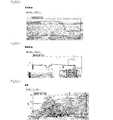
図2は,本発明の電源制御システム100の適用例を概念的に示す図である。図2に示されるように,電源制御システム100は,概念的には,モニタリングシステムと提示システムとから構成される。 FIG. 2 is a diagram conceptually showing an application example of the power
モニタリングシステムでは,インテリジェントテーブルタップ10に接続された各種電気機器50の電力を,電流センサ12を用いてそれぞれ計測し,計測された電力情報をサーバ20の記憶部22に記憶する。なお,図2のデータベースは,図1の記憶部22に対応する。 In the monitoring system, the power of various
また,電気機器50が配置された部屋,家屋又は建物の屋内には,屋内の状態に関する屋内情報を検出するための各種センサが設けられている。これらのセンサを総称して,環境センサとする。環境センサで取得される各種情報は,無線通信によりサーバ20に送信され,データベースとしての記憶部22に記憶される。 In addition, various sensors for detecting indoor information regarding the indoor state are provided in the room, house, or building where the
温度センサは,屋内の温度を計測する。照度センサは,屋内の照度を計測する。人感センサは,屋内での人の移動を検出する。例えば,屋内に複数の人感センサを配置して,人の居場所の変化を検知することで,屋内での人の移動を検出する。開閉センサは,扉の開閉を検知することで,屋内への人の出入りを検出する。 The temperature sensor measures the indoor temperature. The illuminance sensor measures indoor illuminance. The human sensor detects the movement of a person indoors. For example, a plurality of human sensors are arranged indoors, and the movement of a person indoors is detected by detecting a change in the location of the person. The open / close sensor detects the opening and closing of a door, thereby detecting the entry and exit of a person indoors.
提示システムでは,データベースとしての記憶部22に記憶された各種情報を用いて,各電気機器50の消費電力や,行動検出に基づいた省エネアドバイスや,省エネ効果等の情報提示が行われる。 In the presentation system, information such as power consumption of each
次に,本発明の電源制御システム100の使用例として,モニタリングシステムとして用いた場合について,図に基づいて説明する。図3は,本発明の電源制御システムの使用例を示す図である。 Next, as a usage example of the power
図3に示されるように,インテリジェントテーブルタップ10が,屋内電力ライン30に接続されている。図4は,インテリジェントテーブルタップ10の例を示す構成図である。図4に示されるように,リモートIOボード111,複数の電流センサ12,複数のスイッチ部13及びPLCアダプタ14が,ケース内に設けられている。 As shown in FIG. 3, the
リモートIOボード111上には,電力制御部11が回路として形成されている。また,インテリジェントテーブルタップ10の外面には,例えば2つの電源用の凹型接触端子からなるコンセント15が複数設けられている。電流センサ12及びスイッチ部13は,コンセント14の数に対応した数だけ設けられる。1つのコンセント15に対して,電流センサ12及びスイッチ部13が少なくとも1つずつ必要となる。なお,こられの数は,各国のコンセント規格によって異なってくる。なお,図3では,便宜上,1つのコンセント15の分しか,電流センサ12及びスイッチ部13を表示していない。 On the remote IO board 111, a
上述したように,電流センサ12及びスイッチ部13は,電力制御部11により制御されるが,図3に示されるように,電力制御部11から電流センサへ12の制御は,リモートIOボード111の入力ポートを用いて行われ, 電力制御部11からスイッチ部13への制御は,リモートIOボード111の出力ポートを用いて行われる。PLCアダプタ14は,サーバ20とのPLC方式による通信に用いられる。 As described above, the
各スイッチ部13及びPLCアダプタ14に接続された電源コード16の先端には,プラグ17が設けられている。このプラグ17は,例えば2つの電源用の凸型接触端子から構成されている。このプラグ17が屋内電力ライン30に接続されることにより,屋内電力ライン30からの電力がインテリジェントテーブルタップ10に供給される。A
図3に戻って,サーバ20は,PLCアダプタ60を介して,屋内電力ライン30に接続される。これにより,サーバ20は,屋内電力ライン30から電力供給を受けられる。PLCアダプタ60は,インテリジェントテーブルタップ10とサーバ20との間のPLC方式による通信に用いられる。サーバ20とPLCアダプタ60との間は,イーサネット(登録商標)規格に従って接続されている。 Returning to FIG. 3, the
また,サーバ20には,赤外線学習リモコン40がUSB(Universal Serial Bus)により接続されている。図5は,赤外線学習リモコン40の例と,その操作画面を示す図である。図5(a)は,赤外線学習リモコン40の外形を撮影した写真代用図である。図5(a)に示されるように,赤外線学習リモコン40の前面(図5内の手前側)に,複数の赤外線LED(Light Emitting Diode)が配置されている。制御部21による制御信号は,この赤外線LEDから,電気機器50に向けて送信される。図5(b)は,赤外線学習リモコン40の操作画面を示す図である。図5(b)では,エアコンを電気機器50とした際の操作画面を示している。 In addition, an infrared learning
電気機器50は,2つの電源用の凸型接触端子からなるプラグ51を先端に設けた電源コード52を有している。プラグ51は,コンセント15に対応して形状等が決まる。プラグ51は,インテリジェントテーブルタップ10のコンセント15に挿入される。これにより,電源コード52を介して,屋内電力ライン30からの電力が電気機器50に供給される。 The
次に,図1〜図3に基づいて,本発明の電源制御システム100をモニタリングシステムとして動作させた際の処理の流れを説明する。
まず,電気機器50に対してブラウザからの操作がユーザにより行われると,サーバ20の制御部21は,操作内容に対応した制御信号を生成する。ブラウザからの操作は,例えば,サーバ20のキーボード入力やサーバ30とは別のモバイル端末からの信号入力等により行われる。次に,サーバ20の制御部21は,赤外線学習リモコン40を介して,制御信号を電気機器50へ送信する。電気機器50は,制御信号を受信すると,受信した制御信号に応じた動作をする。Next, based on FIGS. 1 to 3, the flow of processing when the power
First, when an operation from the browser is performed on the
例えば,制御信号が電気機器50の電源をオンにする信号である場合,電気機器50は制御信号に従って電気機器50の電源をオンにする。このとき,インテリジェントテーブルタップ10にも,PLCアダプタ60及び屋内電力ライン30を介して,電気機器50の電源をオンにする制御信号が入力される。そして,インテリジェントテーブルタップ10の電力制御部11は,制御信号に従って,スイッチ部13をオンにする。これにより,屋内電力ライン30からの電力が電気機器50に供給され,電気機器50が稼働状態となる。 For example, when the control signal is a signal for turning on the power of the
一方,制御信号が電気機器50の電源をオフにする信号である場合,電気機器50は制御信号に従って電気機器50の電源をオフにする。上記同様,インテリジェントテーブルタップ10にも,PLCアダプタ60及び屋内電力ライン30を介して,電気機器50の電源をオフにする制御信号が入力される。そして,インテリジェントテーブルタップ10の電力制御部11は,制御信号に従って,スイッチ部13をオフにする。これにより,屋内電力ライン30からの電力供給が停止され,電気機器50が非稼働状態となる。 On the other hand, when the control signal is a signal for turning off the
また,インテリジェントテーブルタップ10の電力制御部11は,電流センサ12で計測される電流量に基づいて,電気機器50へ供給した電力を計測する。なお,複数の電気機器50がインテリジェントテーブルタップ10に接続されている場合には,電力制御部11は電気機器50毎に電力を計測する。インテリジェントテーブルタップ10は,計測された電力情報を,屋内電力ライン30を介してサーバ20へ送信する。電力情報を受信したサーバ20の制御部21は,受信した電力情報を記憶部22に記憶する。これにより,電気機器50毎の消費電力が記憶部22に記憶される。 Further, the
また,電気機器50が配置された各環境センサは,屋内の温度や屋内の照度や屋内での人の移動等を検出する。そして,各環境センサは,取得される各種情報を無線通信によりサーバ20へ送信する。これらの環境センサで取得される各種情報は,屋内の状態に関する屋内情報として,制御部21により記憶部22に記憶される。 Each environmental sensor in which the
ユーザは,サーバ20やモバイル端末等にて操作することにより,電気機器50の電力情報や,環境センサにより検出された屋内情報を,出力部23に出力することができる。このとき,制御部21は,記憶部22に記憶されている電力情報や屋内情報に基づいた指令を,例えば表示部等の出力部23に出力する。これにより,ユーザは,各電気機器50に関する電力情報や,屋内の状態に関する情報を,リアルタイムに確認することができる。 The user can output the power information of the
また,制御部21は,環境センサにより検出された屋内情報を取得し,屋内情報に基づいた制御信号を新たに生成してもよい。これにより,屋内の状況に応じた制御信号が生成される。そして,この制御信号が制御部21によってインテリジェントテーブルタップ10及び電気機器50に送信されると,屋内の状況に応じた制御がインテリジェントテーブルタップ10及び電気機器50に対して行われる。 Further, the
例えば,部屋の中のテレビに対して,制御を行う場合について説明する。制御部21は,人感センサや開閉センサによって,部屋に人がいるか否かを検知できる。制御部21は,これらのセンサで検知された環境情報に基づいた制御信号を生成する。例えば,人が部屋に居ないと認識した場合,制御部21はテレビの電源をオフにする制御信号を新たに生成する。そして,制御部21は,この新たな制御信号をインテリジェントテーブルタップ10及びテレビに送信する。テレビは,制御信号に従って当該テレビの電源をオフにする。また,インテリジェントテーブルタップ10は,制御信号に従って,テレビへの電力供給を停止する。このように,人の行動等の屋内情報に対応して,電気機器への電力供給を簡単に停止することができる。この結果,人が意識することなく,効果的に待機電力の消費を抑制でき,省エネ活動が有効に促進される。 For example, a case where control is performed on a television in a room will be described. The
また,記憶部22には,制御部21が送信した制御信号を記憶してもよい。このとき,制御部21は,記憶部22に記憶された制御信号を用いて,電気機器50への電力供給を停止する。すなわち,制御部21は,電気機器50に対して既に過去に送信した制御信号を記憶部22から取得する。そして,制御部21は,取得した制御信号を用いて,インテリジェントテーブルタップ10及び電気機器50に電源をオン又はオフにする信号等を出力する。The
例えば,記憶部22に,ビデオ機器に対する制御信号が記憶されている場合について,説明する。記憶部22には,例えば毎週月曜の午後9時〜10時に特定の番組を録画するという録画予約命令が,制御信号として記憶されているとする。そして,ユーザが録画予約した時間以外にビデオ機器50の電源を入れて,電源を点けっぱなしにしたとする。このとき,制御部21は,記憶部22から録画予約命令の制御信号を取得し,これを再度,インテリジェントテーブルタップ10及びビデオ機器に送信する。インテリジェントテーブルタップ10は,制御信号を受信すると,この制御信号に基づいて,ビデオ機器への電力供給を停止する。このようにして,制御部21が,記憶部22に記憶された録画予約命令の制御信号を用いて,ビデオ機器50への電力供給を停止することができる。これにより,録画予約時間である月曜の午後9時〜10時の間のみ通電し,必要最低限の電力使用によって,予約録画を行うことができる。この結果,効果的に待機電力を抑制でき,省エネ活動が有効に促進される。For example, a case where a control signal for a video device is stored in the
次に,本発明の電源制御システム100の使用例として,提示システムとして用いた場合について説明する。 Next, a case where the power
上述の通り,提示システムでは,データベースとしての記憶部22に記憶された各種情報を用いて,各電気機器50の消費電力や,行動検出に基づいた省エネアドバイスや,省エネ効果等の情報提示が行われる。 As described above, in the presentation system, using various information stored in the
これらの情報提示を行うために,制御部21は,記憶部22に記憶されている電気機器50毎の電力情報や,屋内の温度や屋内の照度や屋内での人の移動等の屋内情報に基づいた指令を,出力部23に出力する。出力部23を表示部としたときの各種情報の表示例を以下に説明する。図6〜図10は,各種情報の表示例を示す図である。 In order to present such information, the
図6は,ブラウザを用いた場合の表示画面の例を示す図である。画面中央には,日毎の総消費電力が示されている。また,画面左には,「機器別消費電力」,「貯金箱」等の複数のメニューが表示される。画面下には,目標設定に関する情報が表示される。 FIG. 6 is a diagram illustrating an example of a display screen when a browser is used. In the center of the screen, the total power consumption per day is shown. Further, on the left side of the screen, a plurality of menus such as “power consumption by device” and “savings box” are displayed. Information about target setting is displayed at the bottom of the screen.
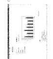
図7(a)は,日毎の総消費電力の表示例を示す図である。横軸には日付,縦軸には消費電力が設定されている。図7(a)において,総消費電力が棒グラフで示されている。また,目標値(図7(a)では4000以下)の範囲に対して,塗りつぶしが行われている。このような表示が提供されることで,ユーザは,各電気機器50の日毎の総消費電力を目標値と共に,確認することができる。ここで,総消費電力は,記憶部22に記憶されている各電気機器50の日毎の電力を合計して,制御部21により算出される。目標値は,ユーザによる操作入力によって入力され,予め記憶部22に記憶されている。 FIG. 7A is a diagram illustrating a display example of the total power consumption for each day. The horizontal axis indicates the date, and the vertical axis indicates the power consumption. In FIG. 7A, the total power consumption is shown as a bar graph. In addition, the filling is performed on the range of the target value (4000 or less in FIG. 7A). By providing such a display, the user can check the total power consumption of each
図7(b)は,機器別消費電力の表示例を示す図である。横軸には時間,縦軸には消費電力が設定されている。図7(b)において,電気機器50毎の消費電力の時間的変化が折れ線グラフで表示されている。このような表示が提供されることで,ユーザは,どの時間にどの電気機器50でどのくらいの電力を消費したいたかについて,確認することができる。 FIG. 7B is a diagram illustrating a display example of the power consumption by device. Time is set on the horizontal axis, and power consumption is set on the vertical axis. In FIG. 7B, the temporal change in power consumption for each
図8(a)は昼光照度の表示例を示す図,図8(b)は照明照度の表示例を示す図である。横軸には時間,縦軸には照度が設定されている。図8(a)及び図8(b)において,照度の時間的変化が折れ線グラフで表示されている。図8(c)は温度の表示例を示す図である。横軸には時間,縦軸には温度が設定されている。図8(c)において,屋内の温度の時間的変化が折れ線グラフで表示されている。これらの表示が提供されることで,ユーザがどのような屋内環境下で生活しているのかを確認することができる。例えば,エアコンの消費電力は,温度との相関性が高いことが知られている。従って,エアコンが設置されている環境が実際にどのようになっているのかの知識を得ることで,エアコンの効率的な制御に役立てることができる。 FIG. 8A shows a display example of daylight illuminance, and FIG. 8B shows a display example of illumination illuminance. Time is set on the horizontal axis, and illuminance is set on the vertical axis. In FIG. 8A and FIG. 8B, the temporal change in illuminance is displayed as a line graph. FIG. 8C is a diagram showing a temperature display example. Time is set on the horizontal axis, and temperature is set on the vertical axis. In FIG.8 (c), the temporal change of indoor temperature is displayed by the line graph. By providing these displays, it is possible to confirm in what indoor environment the user lives. For example, the power consumption of air conditioners is known to have a high correlation with temperature. Therefore, by obtaining knowledge of the actual environment in which the air conditioner is installed, it can be used for efficient control of the air conditioner.
図9は,行動履歴の表示例を示す図である。この表示は,省エネに関して,相応しくない行動をいつしていたかを確認するために提供される。ここで表示される情報は,記憶部22に記憶される電気機器50毎の電力情報及び屋内の状態に関する屋内情報や,予めユーザにより記憶部22に記憶された目標値等の複数の情報を組み合わせることで,生成される。 FIG. 9 is a diagram illustrating a display example of an action history. This indication is provided to confirm when an inappropriate action was taken with regard to energy saving. The information displayed here combines a plurality of pieces of information such as power information for each
図9(a)において,1番上の表示欄には,省エネアドバイスが表示される。ここでは,省エネのためのアドバイスと,その説明が表示される。すなわち,省エネのためには,どんなときにどんな行動を取ればよいのかを説明している。 In FIG. 9A, energy saving advice is displayed in the top display column. Here, advice for energy saving and its explanation are displayed. In other words, it explains what actions should be taken to save energy.
2番目の表示欄には,貯金機能の目標設定を行うためのアイコンが示される。ユーザは,これらのアイコンを用いて,目標値を入力する。入力された目標値は,記憶部22に記憶される。 In the second display column, an icon for setting a target for the saving function is shown. The user inputs a target value using these icons. The input target value is stored in the
3番目の表示欄には,月額損失が表示される。ここでは,現在,提示している日の電力消費を1ヶ月続けた場合における月額の損失が表示される。すなわち,省エネによって期待できる節約料金が示される。この節約料金は,記憶部22に記憶されている各電気機器50の電力情報や目標値等から制御部21によって算出される。 In the third display column, the monthly loss is displayed. Here, the monthly loss when the power consumption on the present day is continued for one month is displayed. In other words, it shows the savings that can be expected from energy conservation. This saving fee is calculated by the
4番目の表示欄では,行動履歴ガントチャートが示される。ここでは,例えば,「Loss Time」では,省エネに相応しくない行動を取っていた時間を赤く表示する。また,「aircon」では,電気機器50(ここではエアコン)の使用時間が表示される。例えば,使用時は黄色,不使用時は斜線で示される。「Place」では,ユーザの所在位置が示される。例えば,外出は緑,研究室がピンク,台所が黄色で示される。これら表示は,人感センサや開閉センサ等の環境センサで検出された情報に基づいて,制御部21によって生成される。「Sunshine」では,例えば,屋内への昼光入射が過度なときにクリーム色で表示される。「light」では,例えば,照明使用時間がクリーム色で示される。この表示情報は,照度センサで検出された情報に基づいて,制御部21によって生成される。「Use machine」では,例えば,電気機器50(ここでは炊飯器)の使用時間がクリーム色で示される。この表示情報は,電気機器50の消費電力の時間的変化に基づいて,制御部21によって生成される。 In the fourth display column, an action history Gantt chart is shown. Here, for example, in “Loss Time”, the time during which an action not suitable for energy saving was taken is displayed in red. In “aircon”, the usage time of the electric device 50 (here, an air conditioner) is displayed. For example, it is yellow when in use and shaded when not in use. “Place” indicates the location of the user. For example, going out is green, laboratory is pink, kitchen is yellow. These displays are generated by the
5番目の表示欄では,温度/照度グラフが示される。この表示欄では,このページで示される省エネ方法に関係のある場合のみグラフが示される。例えば,グラフ中で塗りつぶしが施されている領域が省エネの目安となる。この目安以上となったグラフの領域に対応する時間帯について,エネルギーロスを算出する。 In the fifth display field, a temperature / illuminance graph is shown. In this display column, a graph is shown only when it is related to the energy saving method shown on this page. For example, the area that is filled in the graph is a guideline for energy saving. Energy loss is calculated for the time zone corresponding to the area of the graph that exceeds this guideline.
図9(b)には,ドア又は窓の開閉時間が表示される。図9(a)の4番目の表示欄に示した内容に代えて,図9(b)に示される内容をしてもよい。表示例では,右に目標時間,左に実際の開閉時間が表示されている。この表示情報は,開閉センサで検出された情報に基づいて,制御部21によって生成される。 FIG. 9B shows the opening / closing time of the door or window. Instead of the contents shown in the fourth display field of FIG. 9A, the contents shown in FIG. 9B may be used. In the display example, the target time is displayed on the right and the actual opening / closing time is displayed on the left. This display information is generated by the
図10は,貯金額確認画面の表示例を示す図である。図10中のグラフにおいて,横軸には日にち,縦軸には金額が設定されている。この画面表示では,ユーザにより予め設定された消費電力の目標値に対して,削減された消費電力量を金銭に変換し,これを貯金額として表示している。また,その貯金額の累積額を生じしている。この表示情報は,各電気機器50の電力情報や,記憶部22に予め設定された電力目標値等の情報に基づいて,制御部21によって生成される。このような表示を提供することで,ユーザは消費電力の節約実績を視覚的に確認することができる。 FIG. 10 is a diagram illustrating a display example of the savings amount confirmation screen. In the graph in FIG. 10, the horizontal axis indicates the date, and the vertical axis indicates the amount. In this screen display, the reduced power consumption is converted into money with respect to a target value of power consumption set in advance by the user, and this is displayed as a saving amount. In addition, the accumulated amount of savings is generated. This display information is generated by the
図11は,図10で示した貯金額確認画面を使用するためのフロー図である。図中のSは,ステップ(Step)を意味する。図11に示されるように,ユーザは,各電気機器50の電力情報や,環境センサで検出された屋内情報等を,モニタリングする(ステップ1101)。次に,ユーザは,省エネ度を評価する(ステップ1102)。ここでは,損失見積額を算出することで,省エネ度を評価する。ここで,損失見積額とは,エネルギー消費者であるユーザが無駄な電力を浪費した時間と,当該ユーザによる行動の種類によって算出される削減可能な電力量に対応する金額である。次に,ユーザは,省エネ度の評価結果に基づいて,消費電力の目標値を設定して(ステップ1103),再度,上述した各種情報をモニタリングする(ステップ1104)。再度,ユーザは,省エネ度を評価する(ステップ1105)。ここでは,損失見積額又は貯金額を算出する。そして,新たな目標値を設定して,上述した各種情報をモニタリングする(ステップ1107)。以下,このステップを繰り返し行うことで,ユーザの省エネ活動が促進される。なお,上記損出見積額,貯金額及び目標設定は,省エネアドバイス毎に算出される。 FIG. 11 is a flowchart for using the savings amount confirmation screen shown in FIG. S in the figure means a step. As shown in FIG. 11, the user monitors the power information of each
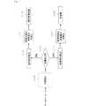
図12は,環境センサにより検出された各種情報に基づいて,損失見積額及び貯金額を算出するための処理を示すフロー図である。まず,行動検出を行う(ステップ1201)。ここでは,データベースとしての記憶部22に記憶されている各種屋内情報に基づいて,ユーザの行動パターンを検出する。すなわち,例えば,ユーザがどんな時間にどこに居ることが多いのか等,ユーザの行動に関する情報を取得する。次に,消費電力の目標値が設定されている場合には(ステップ1202,Yes),消費電力の節約量を改善率で算出する(ステップ1203)。そして,改善率に基づいて,具体的に削減可能な消費電力を算出して(ステップ1204),これを貯金額とする(ステップ1205)。一方,消費電力の目標値が設定されていない場合には(ステップ1202,No),実行時間を算出する(ステップ1206)。この実行時間とは,省エネ活動できなかった時間,つまり,エネルギー消費者であるユーザが無駄な電力を浪費した時間である。そして,実行時間に基づいて,具体的に削減可能な消費電力を算出して(ステップ1207),これを損失見積金額とする(ステップ1208)。 FIG. 12 is a flowchart showing a process for calculating an estimated loss amount and a savings amount based on various information detected by the environmental sensor. First, behavior detection is performed (step 1201). Here, a user's action pattern is detected based on various indoor information stored in the
以上のように,本発明における電源制御システム100では,インテリジェントテーブルタップ10は,制御部21からの制御信号に基づいて,電気機器50A,50Bへの電力供給を停止する。この構成により,インテリジェントテーブルタップ10が,制御部21から電気機器50A,50Bへ送信される制御信号に連動して,電気機器50A,50Bへの電力供給を停止する。この結果,人の手を煩わすことなく,効率よく待機電力を削減することができる。 As described above, in the power
本発明における電源制御システム100において,インテリジェントテーブルタップ10は,制御信号が電気機器50A,50Bの電源をオフにする信号である場合に,電気機器50A,50Bへの電力供給を停止する。この構成により,インテリジェントテーブルタップ10が,電気機器50A,50Bの電源をオフする制御信号に連動して,電気機器50A,50Bへの電力供給を停止する。この結果,人の手を煩わすことなく,電気機器への制御に連動して,効率よく待機電力を削減することができる。 In the power
本発明における電源制御システム100において,インテリジェントテーブルタップ10は,電気機器50A,50Bに供給した電力を計測する。これにより,電気機器50A,50Bの電力使用量を簡単に取得することができる。 In the power
本発明における電源制御システム100において,インテリジェントテーブルタップ10は,電気機器50A,50B毎に,電器機器50A,50Bに供給した電力をそれぞれ計測する。これにより,電気機器50A,50B毎に電力使用量を取得することができる。 In the power
本発明における電源制御システム100では,制御部21は,インテリジェントテーブルタップ10により計測された電力情報を取得し,取得した電力情報に基づいた指令を出力部23へ出力する。これにより,電気機器50A,50Bの電力使用量が出力部23に出力される。この結果,エネルギー消費者が,出力部23の出力を確認することで,電気機器50A,50Bの電力使用量を確認することができる。 In the power
本発明における電源制御システム100では,制御部21は,環境センサにより検出された屋内情報と,インテリジェントテーブルタップ10により計測された電力情報とに基づいた指令を出力部23へ出力する。これにより,電力情報が屋内情報と共に出力部23に出力される。この結果,エネルギー消費者が,出力部23の出力を確認することで,電気機器50A,50Bの電力情報を屋内情報と合わせて得ることができる。 In the power
本発明における電源制御システム100では,記憶部22には,電力情報と屋内情報とが互いに対応して記憶されている。制御部21は,記憶部22に記憶された電力情報及び屋内情報に基づいた指令を出力部23に出力する。これにより,例えば,数時間前,数日前等,過去の電力情報が屋内情報と共に出力部23に出力される。この結果,エネルギー消費者が,出力部23の出力を確認することで,電気機器50A,50Bの過去の電力情報を屋内情報と合わせて得ることができる。In the power
本発明における電源制御システム100では,記憶部22には,制御部21が送信した制御信号が記憶されており,制御部21は,記憶部22に記憶された制御信号を用いて,電気機器50A,50Bへの電力供給を停止する。このように,制御部21は,記憶部22に記憶された制御信号を用いることで,過去に電源機器に対して送信した制御信号を取得し,これに基づいた制御を電源供給機器に対して行うことが行える。In the power
本発明における電源制御システム100では,制御部21は,環境センサにより検出された屋内情報を取得し,屋内情報に基づいた制御信号を新たに生成し,屋内情報に基づいた制御信号を電気機器50A,50B及び電源供給器具10に送信し,電源供給器具10は,屋内情報に基づいた制御信号を用いて,電気機器50A,50Bへの電力供給を停止する。これにより,屋内に状態に応じた制御信号が生成され,屋内情報に合わせた制御を電気機器に対して行うことができる。この結果,人の行動等の屋内情報に対応して,電気機器への電力供給を簡単に停止することができる。 In the power
本発明における電源制御システム100において,好ましくは,前記環境センサは,前記屋内の人の移動,前記屋内の温度又は前記屋内の照度のうち,少なくとも1つを検出する。環境センサにより屋内の人の移動を検出し,これを屋内情報とすることで,屋内情報と電力情報とに基づいて,エネルギー消費者の行動に対応した電力情報を出力部23に出力することができる。また,環境センサにより屋内の温度や照度を検出し,これを屋内情報とすることで,屋内情報と電力情報とに基づいて,電気機器50A,50Bの設置環境を含めた電力情報を出力部23に出力することができる。この結果,エネルギー消費者は,出力部23の出力を確認することで,エネルギー消費者の行動に対応した電力情報や,電気機器の設置環境を含めた電力情報等,省エネのために有益な情報を取得することができる。これらの情報により,エネルギー消費者は,自らの行動を見つめ直す機会が与えられる。そして,エネルギー消費者は,省エネのための目標設定を自己の行動に従って設定することができる。設定された目標に対する省エネ効果の実績を累積して,これを出力部23に出力することで,エネルギー消費者は省エネ効果を随時確認することができる。このようにして,省エネ行動の楽しみをエネルギー消費者に提供することができる。 In the power
本発明における電源制御システム100において,インテリジェントテーブルタップ10と制御部21との間の信号又は情報の送受は,電力線を通信媒体に用いた電力線搬送方式を用いて行われる。このように,既存の電力線を通信媒体に用いているので,新たに信号又は情報の送受信用の器具を設ける必要がなく,コストを低減できる。 In the power
本発明における電源制御システム100において,電気機器50A,50Bは,二つの電源用の凸型接触端子からなるプラグを先端に設けた電源コードを有している。また,インテリジェントテーブルタップ10は,二つの電源用の凹型接触端子からなるコンセントを有している。そして,プラグがコンセントに挿入されることにより,インテリジェントテーブルタップ10が電源コードを介して,電気機器50A,50Bに電力を供給する。これにより,インテリジェントテーブルタップ10と電気機器50A,50Bとを容易に接続することができ,インテリジェントテーブルタップ10から電気機器50A,50Bへ容易に電力を供給できる。 In the power
本発明における電源制御システム100では,本発明の電気機器50にビデオ機器を用い,制御信号には録画予約に関する制御信号を用いた。記憶部22には,制御部21が送信した録画予約に関する制御信号が記憶されており,制御部21は,記憶部22に記憶された録画予約に関する制御信号を用いて,ビデオ機器50への電力供給を停止する。これにより,記憶部22には,ビデオ機器50の録画予約命令等の制御信号が記憶される。従って,人の操作による制御信号の入力がなくても,記憶部22に記憶されている制御信号を用いて,ビデオ機器50の電力供給を制御することができる。例えば,毎週月曜の午後9時〜10時に特定の番組を録画するという録画予約命令が,制御信号として,記憶部22に記憶されているとする。そして,ユーザが録画予約した時間以外にビデオ機器50の電源を入れて,電源を点けっぱなしにしたとする。このような場合においても,制御部21が,記憶部22に記憶された録画予約命令の御信号を用いて,前記ビデオ50への電力供給を停止することができる。この結果,録画予約時間である月曜の午後9時〜10時の間のみ通電し,必要最低限の電力使用によって,予約録画を行うことができる。 In the power
以上、本発明の実施の形態を例示により説明したが、本発明の範囲はこれらに限定されるものではなく、請求項に記載された範囲内において目的に応じて変更又は変形することが可能である。 The embodiments of the present invention have been described above by way of example, but the scope of the present invention is not limited to these, and can be changed or modified in accordance with the purpose within the scope described in the claims. is there.
上記実施の形態の説明では,インテリジェントテーブルタップ10を本発明の電源供給器具として説明したが,コーナータップやトリプルタップを本発明に用いてもよい。コーナータップやトリプルタップは,テーブルタップのように電源コードがなく,その場でコンセントが複数に分岐する構造となっている。 In the description of the above embodiment, the
上記実施の形態の説明では,赤外線学習リモコンを本発明のリモコン部として説明したが,ブルートゥース(Bluetooth)等の無線通信型のリモコンを本発明に用いてもよい。また,サーバ20及び電気機器50の間の通信は,USB(Universal Serial Bus)配線による接続等の有線を媒体とした通信によっても実現できる。 In the above description of the embodiment, the infrared learning remote controller has been described as the remote controller of the present invention. However, a wireless communication type remote controller such as Bluetooth may be used in the present invention. The communication between the
なお,本発明の実施の形態に係る電源制御システム100を,ネットワークに接続してもよい。これにより,各家屋や各建物での消費電力に関する情報等,様々な情報を複数のユーザによって共有することができる。この結果,社会全体の省エネ意識を高めることができる。 Note that the power
本発明は,電気機器に電力を供給するテーブルタップ等の電源供給器具を有する電源制御システムに関する技術分野において利用されうる。例えば,ユビキタスセンサとインテリジェントテーブルタップによる省エネシステムに適用することができる。ユビキタスセンサとは、近年普及しつつあるユビキタス−コンピューティングシステムを利用したセンサであり遍在性を特徴としている。ユビキタスとは人間が介在せずコンピュータ同士が連携して動作する環境をいう。本発明ではインテリジェントテーブルタップを用いて,例えば屋内の状態に関する情報を用いて,電気機器への電力供給を停止することを可能としている。 The present invention can be used in a technical field related to a power supply control system having a power supply device such as a table tap for supplying power to an electric device. For example, it can be applied to an energy saving system using ubiquitous sensors and intelligent table taps. The ubiquitous sensor is a sensor using a ubiquitous-computing system that has been spreading in recent years, and is characterized by ubiquity. Ubiquitous refers to an environment in which computers operate without human intervention. In the present invention, it is possible to stop the power supply to the electric device by using the intelligent table tap, for example, information on the indoor state.
10 インテリジェントテーブルタップ
11 電力制御部
12 電流センサ
13 スイッチ部
20 サーバ
21 制御部
22 記憶部
23 出力部
30 屋内電力ライン
40 赤外線学習リモコン
50A,50B 電気機器
100 電源制御システムDESCRIPTION OF
Claims (15)
Translated fromJapanese前記電気機器(50A,50B)に電力を供給する電源供給器具(10)と,
前記電気機器(50A,50B)及び前記電源供給器具(10)に制御信号を送信する制御部(21)とを備えた電源制御システムであって,
前記電源供給器具(10)は,前記制御信号に基づいて,前記電気機器(50A,50B)への電力供給を停止することを特徴とする電源制御システム。Electrical equipment (50A, 50B),
A power supply device (10) for supplying power to the electrical devices (50A, 50B);
A power control system comprising a control unit (21) for transmitting a control signal to the electrical equipment (50A, 50B) and the power supply instrument (10),
The power supply device (10) stops power supply to the electric devices (50A, 50B) based on the control signal.
前記電源供給器具(10)は,前記制御信号が前記電気機器(50A,50B)の電源をオフにする信号である場合に,前記電気機器(50A,50B)への電力供給を停止する請求項1に記載の電源制御システム。The control unit (21) transmits at least a signal for turning on or off the electric device (50A, 50B) as the control signal to the electric device (50A, 50B) and the power supply device (10). And
The said power supply instrument (10) stops the electric power supply to the said electric equipment (50A, 50B), when the said control signal is a signal which turns off the power supply of the said electric equipment (50A, 50B). The power supply control system according to 1.
前記電源供給器具(10)は,前記電気機器(50A,50B)毎に,前記電器機器(50A,50B)に供給した電力をそれぞれ計測する請求項1又は請求項2に記載の電源制御システム。A plurality of the electric devices (50A, 50B),
The power supply control system according to claim 1 or 2, wherein the power supply device (10) measures electric power supplied to the electric appliances (50A, 50B) for each of the electric appliances (50A, 50B).
前記制御部(21)は,前記電源供給器具(50A,50B)により計測された前記電力情報を取得し,取得した前記電力情報に基づいた指令を前記出力部(23)へ出力する請求項1〜4のいずれかに記載の電源制御システム。An output unit (23) for receiving a command from the control unit (21) and outputting information based on the command;
The said control part (21) acquires the said electric power information measured by the said power supply instrument (50A, 50B), and outputs the instruction | command based on the acquired said electric power information to the said output part (23). The power supply control system in any one of -4.
前記制御部(21)は,前記環境センサにより検出された前記屋内情報と,前記電源供給器具(10)により計測された前記電力情報とに基づいた指令を前記出力部(23)へ出力する請求項1〜5のいずれかに記載の電源制御システム。An environmental sensor that is installed in a room, house, or building in which the electrical devices (50A, 50B) are arranged, and that detects indoor information related to the indoor state;
The control unit (21) outputs a command based on the indoor information detected by the environmental sensor and the power information measured by the power supply device (10) to the output unit (23). Item 6. The power supply control system according to any one of Items 1 to 5.
前記記憶部(22)には,前記電力情報と前記屋内情報とが互いに対応して記憶され,
前記制御部(21)は,前記記憶部(22)に記憶された前記電力情報及び前記屋内情報に基づいた指令を前記出力部(23)に出力する請求項6に記載の電源制御システム。A storage unit (22) capable of exchanging information with the control unit (21);
In the storage unit (22), the power information and the indoor information are stored in association with each other,
The power supply control system according to claim 6, wherein the control unit (21) outputs a command based on the power information and the indoor information stored in the storage unit (22) to the output unit (23).
前記記憶部(22)には,前記制御部が送信した前記制御信号が記憶されており,
制御部(21)は,前記記憶部(22)に記憶された制御信号を用いて,前記電気機器(50A,50B)への電力供給を停止する請求項1〜5のいずれかに記載の電源制御システム。A storage unit (22) capable of exchanging information with the control unit (21);
The storage unit (22) stores the control signal transmitted by the control unit,
The power source according to any one of claims 1 to 5, wherein the control unit (21) uses the control signal stored in the storage unit (22) to stop power supply to the electric devices (50A, 50B). Control system.
制御部(21)は,前記環境センサにより検出された前記屋内情報を取得し,前記屋内情報に基づいた制御信号を新たに生成し,前記屋内情報に基づいた制御信号を前記電気機器(50A,50B)及び前記電源供給器具(10)に送信し,
前記電源供給器具(10)は,前記屋内情報に基づいた制御信号を用いて,前記電気機器(50A,50B)への電力供給を停止する請求項1〜5のいずれかに記載の電源制御システム。An environmental sensor that is installed in a room, house, or building in which the electrical devices (50A, 50B) are arranged, and that detects indoor information related to the indoor state;
The control unit (21) acquires the indoor information detected by the environmental sensor, newly generates a control signal based on the indoor information, and transmits the control signal based on the indoor information to the electric device (50A, 50B) and the power supply device (10),
The power supply control system according to any one of claims 1 to 5, wherein the power supply device (10) stops power supply to the electric devices (50A, 50B) using a control signal based on the indoor information. .
前記電源供給器具(10)は,コンセントを有し,前記プラグが前記コンセントに挿入されることにより,前記電源コードを介して,前記電気機器(50A,50B)に電力を供給する請求項1〜11のいずれかに記載の電源制御システム。The electrical equipment (50A, 50B) has a power cord provided with a plug at the tip,
The said power supply instrument (10) has an outlet, and supplies electric power to the said electric equipment (50A, 50B) through the said power cord by inserting the said plug into the said outlet. The power supply control system according to any one of 11.
前記ビデオ機器(50A,50B)に電力を供給する電源供給器具(10)と,
前記ビデオ機器(50A,50B)及び前記電源供給器具(10)に録画予約に関する制御信号を送信する制御部(21)と,
前記制御部(21)と情報の授受を行うことができる記憶部(22)を備えた電源制御システムであって,
前記記憶部(22)には,前記制御部が送信した前記録画予約に関する制御信号が記憶されており,
制御部(21)は,前記記憶部(22)に記憶された前記録画予約に関する制御信号を用いて,前記電気機器(50A,50B)への電力供給を停止する電源制御システム。Video equipment (50A, 50B),
A power supply device (10) for supplying power to the video equipment (50A, 50B);
A control unit (21) for transmitting a control signal relating to recording reservation to the video equipment (50A, 50B) and the power supply device (10);
A power supply control system including a storage unit (22) capable of exchanging information with the control unit (21),
The storage unit (22) stores a control signal related to the recording reservation transmitted by the control unit,
The control unit (21) is a power supply control system that stops power supply to the electric devices (50A, 50B) using a control signal related to the recording reservation stored in the storage unit (22).
Priority Applications (1)
| Application Number | Priority Date | Filing Date | Title |
|---|---|---|---|
| JP2009053284AJP2010213367A (en) | 2009-03-06 | 2009-03-06 | Energy saving system using ubiquitous sensor and intelligent table tap |
Applications Claiming Priority (1)
| Application Number | Priority Date | Filing Date | Title |
|---|---|---|---|
| JP2009053284AJP2010213367A (en) | 2009-03-06 | 2009-03-06 | Energy saving system using ubiquitous sensor and intelligent table tap |
Publications (1)
| Publication Number | Publication Date |
|---|---|
| JP2010213367Atrue JP2010213367A (en) | 2010-09-24 |
Family
ID=42972948
Family Applications (1)
| Application Number | Title | Priority Date | Filing Date |
|---|---|---|---|
| JP2009053284APendingJP2010213367A (en) | 2009-03-06 | 2009-03-06 | Energy saving system using ubiquitous sensor and intelligent table tap |
Country Status (1)
| Country | Link |
|---|---|
| JP (1) | JP2010213367A (en) |
Cited By (11)
| Publication number | Priority date | Publication date | Assignee | Title |
|---|---|---|---|---|
| WO2012063388A1 (en)* | 2010-11-09 | 2012-05-18 | パナソニック株式会社 | Power supply control device and power supply control method |
| JP2013058916A (en)* | 2011-09-08 | 2013-03-28 | Osaka Gas Co Ltd | Standby power reduction system for electric apparatus |
| JP2013134603A (en)* | 2011-12-26 | 2013-07-08 | Daiwa House Industry Co Ltd | Energy management system and energy management method |
| JP2014039416A (en)* | 2012-08-17 | 2014-02-27 | Masahide Kin | System and device of feeding power to personal computer having built-in or outer-equipped battery |
| CN103645686A (en)* | 2013-11-22 | 2014-03-19 | 上海交通大学 | An electric appliance remote control system based on a cloud platform and a method |
| JP2014514896A (en)* | 2011-02-25 | 2014-06-19 | イーカーブ、インコーポレイテッド | Queue access to shared power supply |
| CN103996935A (en)* | 2014-02-27 | 2014-08-20 | 郑启文 | Energy saving socket and control method for the same |
| JP2015519859A (en)* | 2012-04-27 | 2015-07-09 | ヴィオアース ホールディングス リミテッド | Energy saving and / or safety device |
| JP2016170814A (en)* | 2016-06-16 | 2016-09-23 | 株式会社クボタ | Farming system and farm machine |
| CN106450951A (en)* | 2016-09-30 | 2017-02-22 | 广西大学 | Wireless intelligent power-saving socket |
| US9720475B2 (en) | 2013-09-04 | 2017-08-01 | Ricoh Company, Ltd. | Information processing system, information processing device, and information processing method |
- 2009
- 2009-03-06JPJP2009053284Apatent/JP2010213367A/enactivePending
Cited By (15)
| Publication number | Priority date | Publication date | Assignee | Title |
|---|---|---|---|---|
| JP2012105427A (en)* | 2010-11-09 | 2012-05-31 | Panasonic Corp | Power feeding control apparatus and power feeding control method |
| CN103155351A (en)* | 2010-11-09 | 2013-06-12 | 松下电器产业株式会社 | Power supply control device and power supply control method |
| US9134709B2 (en) | 2010-11-09 | 2015-09-15 | Panasonic Intellectual Property Management Co., Ltd. | Power supply control device and power supply control method |
| WO2012063388A1 (en)* | 2010-11-09 | 2012-05-18 | パナソニック株式会社 | Power supply control device and power supply control method |
| JP2014514896A (en)* | 2011-02-25 | 2014-06-19 | イーカーブ、インコーポレイテッド | Queue access to shared power supply |
| JP2013058916A (en)* | 2011-09-08 | 2013-03-28 | Osaka Gas Co Ltd | Standby power reduction system for electric apparatus |
| JP2013134603A (en)* | 2011-12-26 | 2013-07-08 | Daiwa House Industry Co Ltd | Energy management system and energy management method |
| JP2015519859A (en)* | 2012-04-27 | 2015-07-09 | ヴィオアース ホールディングス リミテッド | Energy saving and / or safety device |
| JP2014039416A (en)* | 2012-08-17 | 2014-02-27 | Masahide Kin | System and device of feeding power to personal computer having built-in or outer-equipped battery |
| US9720475B2 (en) | 2013-09-04 | 2017-08-01 | Ricoh Company, Ltd. | Information processing system, information processing device, and information processing method |
| CN103645686A (en)* | 2013-11-22 | 2014-03-19 | 上海交通大学 | An electric appliance remote control system based on a cloud platform and a method |
| CN103996935A (en)* | 2014-02-27 | 2014-08-20 | 郑启文 | Energy saving socket and control method for the same |
| CN103996935B (en)* | 2014-02-27 | 2015-12-02 | 郑启文 | A kind of energy-saving socket and control method thereof |
| JP2016170814A (en)* | 2016-06-16 | 2016-09-23 | 株式会社クボタ | Farming system and farm machine |
| CN106450951A (en)* | 2016-09-30 | 2017-02-22 | 广西大学 | Wireless intelligent power-saving socket |
Similar Documents
| Publication | Publication Date | Title |
|---|---|---|
| JP2010213367A (en) | Energy saving system using ubiquitous sensor and intelligent table tap | |
| JP6306727B2 (en) | Smart home scene switching method and system | |
| US9106099B2 (en) | Power monitoring system | |
| Kadam et al. | Smart home system | |
| US20170336770A1 (en) | System and method for conrolling energy consuming devices within a building | |
| TWI467878B (en) | Power monitoring and control system | |
| AU2012100135A4 (en) | Power sensor | |
| KR100909598B1 (en) | Standby power control and power consumption display device using outlet with standby / continuous power selection | |
| AU2012100197A4 (en) | Power sensor | |
| JP5173369B2 (en) | Power management system | |
| KR101470448B1 (en) | A smart grid for household meter and its control method | |
| US20150303693A1 (en) | Power control system and method thereof | |
| US20120316698A1 (en) | Electrical power distribution and control system and method for remotely controlling power delivery through IP addressable electrical power supply equipment and scanning a network for power control devices | |
| KR101843820B1 (en) | Smart multitap and smart multitap system using thereof | |
| CN103004136B (en) | Network system | |
| TWM526148U (en) | Intelligent home monitoring system | |
| AU2011101402C4 (en) | Power monitoring system with remote sensing and alerting | |
| CN104932283A (en) | Energy-saving household control system | |
| CN104216309A (en) | Intelligent standby powering on and off device and method | |
| AU2012216717B2 (en) | Electrical supply system | |
| EP2539812B1 (en) | An execution method of one function of a plurality of functions at a component | |
| CN111812994A (en) | Environment perception controller | |
| CN207011051U (en) | Outdoor scene feeds back lamp control system | |
| KR101173919B1 (en) | A power supply control device for cutting off stand-by electric power using touch screen | |
| CN205249548U (en) | Intelligence light control system based on WIFI |