JP2010211577A - Information reader - Google Patents
Information readerDownload PDFInfo
- Publication number
- JP2010211577A JP2010211577AJP2009057684AJP2009057684AJP2010211577AJP 2010211577 AJP2010211577 AJP 2010211577AJP 2009057684 AJP2009057684 AJP 2009057684AJP 2009057684 AJP2009057684 AJP 2009057684AJP 2010211577 AJP2010211577 AJP 2010211577A
- Authority
- JP
- Japan
- Prior art keywords
- guide
- information
- display
- card
- unit
- Prior art date
- Legal status (The legal status is an assumption and is not a legal conclusion. Google has not performed a legal analysis and makes no representation as to the accuracy of the status listed.)
- Granted
Links
Images


Landscapes
- User Interface Of Digital Computer (AREA)
- Near-Field Transmission Systems (AREA)
Abstract
Translated fromJapaneseDescription
Translated fromJapaneseノートパソコンなどのモバイルPCに設けられた非接触ICカードリーダライタとICカードなどの携帯機器との間での短距離通信の通信成功率を高める技術に関する。 The present invention relates to a technology for increasing the communication success rate of short-range communication between a non-contact IC card reader / writer provided in a mobile PC such as a notebook personal computer and a portable device such as an IC card.
ICカードは、個人認証用のIDカードとして、あるいは、課金決済用の電子マネーとして広く使用されている。携帯電話器も同様の目的で使用できるものが実用化されてきている。ICカードや携帯電話のような携帯機器をノートパソコンなどのモバイルPCにかざして携帯機器とモバイルPCとの間で通信を行い、個人認証や課金決済を行う際には、通信が確実に行えるようにする必要がある。携帯機器をモバイルPCのどの位置にかざすべきかを、ユーザに適切に提示することが望まれている。 The IC card is widely used as an ID card for personal authentication or as electronic money for billing settlement. Mobile phones that can be used for the same purpose have been put into practical use. Hold a mobile device such as an IC card or mobile phone over a mobile PC such as a notebook computer to communicate between the mobile device and the mobile PC so that communication can be reliably performed when performing personal authentication or billing settlement. It is necessary to. It is desired to appropriately present to the user which position on the mobile PC the portable device should be held over.
物理的なガイド機構を必要とすることなく、容易に情報記憶媒体を予め定める通信可能な位置に誘導することができる通信装置が知られている。例えば、表示装置と操作部を備えたハンディターミナルで、操作部の裏面部側から近接するICカードと通信可能なものがある。このハンディターミナルでは、ICカードと無線通信するときに、ICカードを配置すべき位置を表す配置位置情報をガイドマーク情報としてメディアガイド位置記憶部に記憶しておき、表示装置上にこのガイドマークを表示する。ユーザは、ICカードをガイドマークに従ってかざすことにより、ICカードとハンディターミナルとの通信を行う。ICカードによってアンテナの位置が異なる場合、ユーザがICカードの種類を選択すると、そのICカードに適したガイドマークの表示位置を選択してICカードが確実に認識できるようにする(例えば、特許文献1)。 There is known a communication device that can easily guide an information storage medium to a predetermined communicable position without requiring a physical guide mechanism. For example, there is a handy terminal provided with a display device and an operation unit, which can communicate with an IC card adjacent from the back side of the operation unit. In this handy terminal, when wirelessly communicating with an IC card, arrangement position information indicating a position where the IC card should be arranged is stored as guide mark information in a media guide position storage unit, and this guide mark is displayed on the display device. indicate. The user performs communication between the IC card and the handy terminal by holding the IC card according to the guide mark. When the position of the antenna differs depending on the IC card, when the user selects the type of IC card, the display position of the guide mark suitable for the IC card is selected so that the IC card can be surely recognized (for example, Patent Documents). 1).
情報読取側のアンテナ体と電子カードのアンテナ体とを再現性良く整合できるようにすると共に、不慣れなユーザにおいても、インターネット上で各種認証/決済処理等を簡単かつ手軽に実行できるようにする情報読取装置が知られている。この情報読取装置は、アンテナ体を有した非接触方式のICカードと、このICカードから情報を読み取って情報処理する情報読取装置とを備え、表示装置はICカードから情報を読み取るICカードリーダライタと、この情報を読み取る際に、ICカードをかざす位置を固定的に表示する液晶表示装置と、この液晶表示装置の表面側又は裏面側に配置されると共にICカードリーダライタに接続されたアンテナ体とを有する(例えば、特許文献2)。
従来のICカードの読取装置ではユーザにICカードをかざす位置を適切に提示するために表示装置上にガイド図形を表示するが、ガイド図形の表示位置は、特許文献2のようにICカードの種類と無関係に固定であったり、特許文献1のようにICカードの種類ごとに固定であった。そのため、ICカードや読取装置の個体差によるアンテナ位置の変動やユーザの癖によるICカードとガイド図形とのずれにより、ユーザが固定位置に表示されたガイド図形に合わせてICカードをかざしたつもりでも、ICカードのアンテナ中心と読取装置のアンテナ中心がずれてしまい頻繁に通信エラーが発生するといった問題があった。 In a conventional IC card reader, a guide graphic is displayed on the display device in order to appropriately present the position where the IC card is held to the user. The display position of the guide graphic is the type of the IC card as in
本発明は、ガイド図形の表示位置を動的に変更することで、ICカードや読取装置の個体差やユーザの癖に対応してICカードと読取装置との間の通信を良好に保つことを目的とする。 The present invention dynamically keeps the communication between the IC card and the reading device corresponding to individual differences of the IC card and the reading device and user's habits by dynamically changing the display position of the guide graphic. Objective.
電波を通過させる液晶表示装置の裏に設置されたICカードリーダライタの利用時に、ICカードをかざす位置をガイド図形として表示装置に表示する本発明のICカードの読取装置は、上記の課題を解決するために、以下のように構成される。
(1)本発明の請求項1記載の情報読取装置は、携帯機器と無線通信を行う無線通信部と、携帯機器をかざす位置を示すためのガイド図形を表示する表示部と、ガイド図形の表示に必要な情報をガイド図形表示情報として格納する記憶部と、ガイド図形表示情報に基づきガイド図形を表示部に表示させる制御部とを具備し、制御部は、携帯機器と無線通信部との間の通信状態を検出した結果である通信状態検出結果に基づいて、ガイド図形の表示位置を変更するものである。When using an IC card reader / writer installed on the back of a liquid crystal display device that allows radio waves to pass through, the IC card reader of the present invention that displays the position where the IC card is held over as a guide figure on the display device solves the above problems. In order to do so, it is configured as follows.
(1) An information reading apparatus according to
このように、ガイド図形の表示位置が携帯機器と無線通信部との間の通信状態が悪い間は変更されることで、通信状態がより良くなる位置(携帯機器のアンテナ中心と情報読取装置のアンテナ中心がより近くなる位置)にガイド図形の表示位置が近づいて行き、結果として、情報読取装置による携帯機器の情報読取が繰り返されるうちにより確実になっていく。
(2)本発明の請求項2記載の情報読取装置は、携帯機器と無線通信を行う無線通信部と、携帯機器をかざす位置を示すためのガイド図形を表示する表示部と、ガイド図形の表示に必要な情報をガイド図形情報として格納する記憶部と、ガイド図形表示情報に基づきガイド図形を表示部に表示させる制御部とを具備し、制御部が、ガイド図形を複数の表示位置に表示し、複数の表示位置のそれぞれにおいて携帯機器と無線通信部との間の通信状態を検出した結果である複数の通信状態検出結果を取得し、複数の通信状態検出結果に基づいて複数の表示位置の中で通信状態が相対的に良好と判断される表示位置にガイド図形を表示するものである。In this way, the display position of the guide graphic is changed while the communication state between the portable device and the wireless communication unit is poor, so that the communication state is improved (the antenna center of the portable device and the information reading device). The display position of the guide figure approaches the position where the antenna center is closer, and as a result, the information reading of the portable device by the information reading device is repeated more reliably.
(2) An information reading apparatus according to
このように、ガイド図形を複数の表示位置に表示して、各表示位置における携帯機器と無線通信部との間の通信状態検出結果の比較によって最良のガイド図形の表示位置を決定することで、使用する携帯機器が特定のものに限られている場合は、一度、ガイド図形の表示位置を決定されれば、情報読取装置による携帯機器の情報読取のたびに携帯機器と無線通信部との間の通信状態の検出をする必要がないため、情報読取装置の処理の負荷を軽減できる。 In this way, by displaying the guide graphic at a plurality of display positions and determining the best guide graphic display position by comparing the communication state detection results between the mobile device and the wireless communication unit at each display position, If the mobile device to be used is limited to a specific one, once the display position of the guide graphic is determined, the mobile phone and the wireless communication unit are read each time information is read from the mobile device by the information reader. Since it is not necessary to detect the communication state, the processing load on the information reading apparatus can be reduced.
本発明により、ICカードや読取装置の個体差やユーザの癖に関係なく、非接触ICカードリーダライタなどを備えた情報読取装置と携帯機器との間の通信が確保できる。 According to the present invention, communication between an information reading apparatus including a non-contact IC card reader / writer and a portable device can be ensured regardless of individual differences of IC cards and reading apparatuses and user's habits.
本発明の情報読取装置の実施形態について図面を参照して説明する。なお、実施の形態において同じ符号を付した構成要素が同様の動作を行う場合には、再度の説明を省略する場合がある。 An embodiment of an information reading apparatus of the present invention will be described with reference to the drawings. In addition, when the component which attached | subjected the same code | symbol performed in embodiment performs the same operation | movement, description may be abbreviate | omitted again.
(実施の形態1)
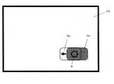
図1は、本実施の形態1の情報読取装置の使用形態を示す図である。
本実施の形態1では、情報読取装置1はノートPCであり、液晶表示器などの表示部10を備えている。表示部10の表面または裏面には、アンテナ4が設けられている。ICカード2をアンテナ4に近づけると、ICカード2が放射する電波をアンテナ4が検知して、情報読取装置1とICカード2との間で通信が行われる。情報読取装置1は、ICカード2の内部に記憶されている情報を読み取ることができる。また、情報読取装置1はアンテナ4を介してICカード2に情報を送信し、ICカード2は受け取った情報を記憶することもできる。(Embodiment 1)
FIG. 1 is a diagram illustrating a usage pattern of the information reading apparatus according to the first embodiment.
In the first embodiment, the
表示部10には、アンテナ4を囲むようにガイド図形3が表示される。ガイド図形3は、ユーザが表示部10のどの位置にICカード2をかざせばよいかの目安情報になる。なお、アンテナ4の位置に、アンテナ4を示す図形を表示してもしなくてもよい。 A
ICカード2の代わりに課金決済機能を有する携帯電話器などでもよい。ICカード2や携帯電話器などを纏めて、以下の説明では、携帯機器と呼ぶことにする。 Instead of the
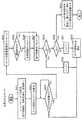
図2は、本実施の形態1の情報読取装置1のブロック構成図である。
情報読取装置1は、表示部10、無線通信部11、制御部12、記憶部13、メディア情報取得部14を具備する。また、ICカード2は、カード情報記憶部20と無線通信部21を具備する。FIG. 2 is a block configuration diagram of the
The
無線通信部11は、アンテナ4を備えており、無線通信部21との間で無線通信を行う。アンテナ4は表示部10の表面または裏面に設置されている。記憶部13は、ガイド図形3を表示するためのガイド図形情報とガイド表示位置情報を記憶している。ガイド図形情報は、ガイド図形3の形状を表し、ガイド図形3を生成するための情報であり、ガイド表示位置情報は、ガイド図形3の表示部10上での表示位置座標を表す情報である。ガイド表示位置情報は種々の表現が可能である。以下にその一例を示す。表示部10の画面上の位置をXY座標で表し、(Xg、Yg)をガイド図形3の中心位置とすることにすれば、(Xg、Yg)によりガイド図形3の表示位置を表示部10上で規定できる。 The
制御部12は、ガイド図形情報とガイド表示位置情報を記憶部13より読み出し、ガイド図形情報とガイド表示位置情報に基づいてガイド図形3を生成し、表示部10に表示させる。また、制御部12は、無線通信部11で受信エラーが起こったか否かを判定して、その判定結果の基づいてガイド図形3の表示位置を変更する。表示位置の変更処理については後述する。メディア情報取得部14は、ICカード2の種類や形式を示す識別情報を取得し、識別情報に基づきガイド図形3の形状や表示位置を制御部12に供給する。 The
カード情報記憶部20は、ICカード2のID情報、顧客情報、課金情報、クレジット関連情報などを格納している。無線通信部21は、無線通信部11と無線通信を行い、情報読取装置1からの指示に従って、カード情報記憶部20からID情報、顧客情報、課金情報、クレジット関連情報などを必要に応じて読み出して情報読取装置1の無線通信部11に送信する。 The card
本実施の形態1では、無線通信部11と無線通信部21間の無線通信が通信失敗か否かを情報読取装置1が判定し、通信失敗の場合には、情報読取装置1は、ガイド図形3の表示位置を徐々に変更し、ユーザにICカード2をかざす位置を変更させて、通信が成功するようにする。
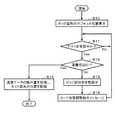
本実施の形態1における情報読取装置1のガイド図形表示処理を示すフローチャートを図5に示す。
制御部12は、(ステップS10)において、ガイド図形情報とガイド表示位置情報を記憶部13より読み出し、ガイド図形情報とガイド表示位置情報に基づいてガイド図形3を生成して表示部10に表示させる。このガイド図形情報とガイド表示位置情報は予め用意されたデフォルトのデータである。次に(ステップS11)に進み、制御部12は、無線通信部11がアンテナ4で電波を受信しているかどうか判定する。電波を受信していない場合はNoであり、(ステップS11)を繰り返す。ICカード2がかざされていない場合、アンテナ4は周囲の雑音電波を検出しており、ICカード2の信号電波を認識できない状態である。ICカード2がガイド図形3に合わせてかざされると、アンテナ4での受信電波強度は、ICカード2の信号電波として認識できる状態になり、(ステップS11)の判定はYesとなる。In the first embodiment, the
FIG. 5 is a flowchart showing guide graphic display processing of the
In (Step S10), the
(ステップS11)においてYesになると(ステップS12)に進み、制御部12は、通信状態の良否の判定を行う。すなわち、制御部12は、受信した信号を復調して受信エラーが起こったか否かを判定する。受信エラーが起こらなかった場合は通信成功でYesであり、(ステップS15)に進み、通信データの読み書きを行う。具体的には、ICカード2から受信した情報を記憶部13に書き込む。なお、制御部12は、(ステップS15)において、新しいガイド表示位置情報を次回のデフォルト値として記憶部13に格納し、(ステップS10)でのガイド図形3の表示に使用してもよい。 When it becomes Yes in (Step S11), the process proceeds to (Step S12), and the
受信エラーが起こった場合は(ステップS12)において通信失敗でNoとなり、制御部12は(ステップS13)に進み、ガイド図形3を所定の方向へ所定距離だけ移動して表示させる。更に、新しいガイド表示位置情報を次回のデフォルト値として記憶部13に格納する。次に制御部12は(ステップS14)に進み、「ICカードをガイド図形に近づけて下さい。」あるいは「データが読み取れませんでした。もう一度、カードをかざして下さい。」というようなカード位置調整指示のメッセージを表示部10のガイド図形3の近傍に表示する。なお、ガイド図形3とメッセージを点滅させてユーザの注意を喚起してもよい。メッセージは、スピーカ(図示しない)により音声でユーザに提示してもよい。次に、制御部12は(ステップS11)に戻り、無線通信部11を介して再度通信を試みる。 If a reception error occurs (No in step S12) due to communication failure, the
図3は本実施の形態1の情報読取装置のガイド図形表示を示す図であり、デフォルト位置のガイド図形3aを左方向へ移動してガイド図形3bに変化させる例である。ユーザは、ICカード2を左方向へ移動させることにより、アンテナ4とICカード2のアンテナとの距離を縮めることができるので、通信成功となる可能性を高くできる。 FIG. 3 is a diagram showing guide graphic display of the information reading apparatus of the first embodiment, and is an example in which the guide graphic 3a at the default position is moved leftward and changed to the guide graphic 3b. Since the user can reduce the distance between the
(ステップS11)において、無線通信部11がアンテナ4で電波を受信しているかどうかの判定は、受信電波強度の大小の判定により行える。(ステップS12)における通信状態の良否の判定は、受信情報の誤り検出の有無や誤り訂正処理の成否により行うことができる。なお、(ステップS12)における通信状態の良否の判定を、受信電波強度の大小の判定により行ってもよく、その場合は、受信電波強度が十分に大きい場合に通信成功と判定すればよい。 In (step S11), it can be determined whether the
ガイド図形3aがガイド図形3bに移動したことにより、電波強度が減少したり、誤り検出が増加したり、あるいは誤り訂正処理がより困難になったりした場合には、ガイド図形3aを次に移動させる際に、移動方向をガイド図形3bとは逆の方向に変更する処理を行っても良い。あるいは、実施の形態5にて後述するように、もとのガイド表示位置の周囲の位置を探索するようにしてもよい。 When the radio wave intensity decreases, error detection increases, or error correction processing becomes more difficult due to the movement of the guide graphic 3a to the guide graphic 3b, the guide graphic 3a is moved next. At this time, a process of changing the moving direction to a direction opposite to the guide figure 3b may be performed. Alternatively, as described later in the fifth embodiment, a position around the original guide display position may be searched.
(実施の形態2)
本実施の形態2では、「位置合わせモード」を設け、p通りのガイド図形の表示位置を用意しておき、それぞれ表示位置に対してn回の読み取り試行を行わせ、読み取りの失敗率が最も低くなるガイド図形の位置をガイド図形表示位置とする。図4は、ガイド図形3a、3b、3cの3つ、すなわち、p=3通りの表示位置を用意した場合の例である。ガイド図形3a、3b、3cの内で最も失敗率が低いガイド図形を選択して使用する。(Embodiment 2)
In the second embodiment, an “alignment mode” is provided, p display positions of guide figures are prepared, and n reading trials are performed for each display position, and the reading failure rate is the highest. The position of the guide graphic that is lowered is set as the guide graphic display position. FIG. 4 shows an example in which three guide figures 3a, 3b, and 3c, that is, p = 3 display positions are prepared. Of the guide figures 3a, 3b and 3c, the guide figure having the lowest failure rate is selected and used.
本実施の形態2における情報読取装置1の構成図は図2と同様のものである。
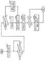
本実施の形態2における情報読取装置1のガイド図形表示処理を示すフローチャートを図6に示す。The configuration diagram of the
FIG. 6 is a flowchart showing a guide graphic display process of the
以下の説明において、ガイド図形情報をG、ガイド図形のXY座標上の表示位置を示すガイド表示位置情報をDjとする。ガイド図形情報Gに基づくガイド図形をガイド表示位置情報Djが示す位置に表示した場合のガイド図形3をガイド図形Gjと呼ぶことにする。ここで、j=1、2、3、・・・・、pであり、ガイド図形はp通り用意される。ガイド図形Gjに対する無線通信の試行回数をRjで表す。各ガイド図形Gjに対する試行回数はそれぞれn回であるので、試行回数はRj=1、2、3、・・・・、nと増加する。ガイド図形Gjが表示されている状態での無線通信の失敗回数を失敗回数=Fjとする。 In the following description, the guide graphic information is G, and the guide display position information indicating the display position of the guide graphic on the XY coordinates is Dj. The guide graphic 3 when the guide graphic based on the guide graphic information G is displayed at the position indicated by the guide display position information Dj is referred to as a guide graphic Gj. Here, j = 1, 2, 3,..., P, and p guide figures are prepared. The number of trials of wireless communication for the guide graphic Gj is represented by Rj. Since the number of trials for each guide graphic Gj is n times, the number of trials increases as Rj = 1, 2, 3,..., N. The number of times of wireless communication failure in the state where the guide graphic Gj is displayed is the number of failures = Fj.
制御部12は、最初に(ステップS21)において、数値p、nおよびj=1、i=1を設定して記憶部13に格納する。数値p、nは、あらかじめ記憶部13に格納しておいてもよい。また、制御部12は、記憶部13内のp個の試行回数Rjとp個の失敗回数Fjとを0に初期化する。制御部12は、次に(ステップS22)に進み、ガイド図形Gj(j=1)を生成して表示部10に表示させる。制御部12は(ステップS23)に進み、無線通信部11がアンテナ4で電波を受信しているかどうか判定する。電波を受信していない場合は判定はNoであり、(ステップS23)を繰り返す。(ステップS23)においてYesになると、(ステップS24)に進み、「ICカードをガイド図形にかざして下さい。」というようなカード位置調整指示のメッセージを表示部10のガイド図形Gjの近傍に表示して、ユーザにICカード2をかざす位置を正しく調整させる。制御部12は次に(ステップS25)に進み、受信エラーが起こったか否うかを判定する。通信失敗の場合は判定はNoになり、制御部12は(ステップS26)に進み、失敗回数Fj→Fj+1とし、次に(ステップS27)に進み、試行回数Rj→Rj+1とする。 At first (step S21), the
通信成功の場合は(ステップS25)においてYesとなり、制御部12は(ステップS27)に進み、試行回数Rj→Rj+1とする。失敗回数Fjは増さない。次に、制御部12は(ステップS28)に進み、iがnに到達したかどうかを判定する。判定がNoの場合は(ステップS29)に進み、制御部12はiを1増加し、iがnに到達するまで、(ステップS23)〜(ステップS27)の処理ループを繰り返す。(ステップS28)においてYesになると、ガイド図形Gjについてのn回の試行が完了状態になっている。制御部12は(ステップS30)に進み、jがpに到達したかどうか判定し、Noの場合には制御部12はjを1増加し、jがpに到達するまで、(ステップS23)〜(ステップS32)の2重ループ処理を繰り返す。 If the communication is successful (Yes in Step S25), the
(ステップS30)においてYesになると、p個のガイド図形Gj(j=1〜p)に対して、それぞれn回ずつの試行が完了した状態になっている。制御部12は(ステップS33)に進み、j=1〜pのp個の失敗率を算出し、最小失敗率であるガイド図形Gjを記憶する。具体的には、制御部12は、ej=Fj/Rjをj=1〜pのp個算出し、その中の最小値のjを選び、失敗率が最小であるjに対応するガイド図形Gjのガイド表示位置情報Djを記憶部13に格納する。 If “Yes” in (Step S30), n trials have been completed for each of the p guide figures Gj (j = 1 to p). The
制御部12は、ICカード2の読み取りを実際に行おうとする場合には、上記「位置合わせモード」において選ばれたガイド表示位置情報Djとガイド図形情報Gjとを用いてejが最小となるガイド図形Gj(min)を生成して表示部10に表示させる。ユーザがガイド図形Gj(min)に従って、ICカード2を表示部10上にかざすので、通信成功の確率が高くなる。 When actually reading the
上記説明では、通信成功か通信失敗かのいずれかの判定をn回重ねることにより、失敗率を算出した。アンテナ4における電波強度値の計測、通信データの誤り検出率の計測、誤り訂正の成功率などの計測により、通信失敗率を評価してもよい。電波強度値が高いほど、通信データの誤り検出率が低いほど、誤り訂正の成功率が高いほど、失敗率は低くなる。この評価方法の場合は、計測の回数nを少なくしたり、n=1回にすることもできるので、ユーザの負担を低減できる。 In the above description, the failure rate is calculated by repeating the determination of either communication success or communication failure n times. The communication failure rate may be evaluated by measuring the radio field intensity value at the
(実施の形態3)
本実施の形態3では、n回の実使用における失敗率を計算、記憶しておいて、基準値Eを超えれば、次回、予め決めておいたルールでガイド図形3の表示位置を移動させる。
本実施の形態3における情報読取装置1の構成図は図2と同様である。
本実施の形態における情報読取装置1のガイド図形表示処理を示すフローチャートを図7に示す。(Embodiment 3)
In the third embodiment, the failure rate in n actual use is calculated and stored, and if the reference value E is exceeded, the display position of the guide graphic 3 is moved next time according to a predetermined rule.
The configuration diagram of the
FIG. 7 shows a flowchart showing guide graphic display processing of the
制御部12は、(ステップS41)において、記憶部13に格納されたガイド表示位置情報に従ってガイド図形3を表示部10に表示させる。次に(ステップS42)に進み、制御部12は、無線通信部11がアンテナ4で電波を受信しているかどうか判定する。電波を受信していない場合には判定はNoであり、(ステップS42)を繰り返す。(ステップS42)においてYesになると、制御部12は(ステップS43)に進み、受信エラーが起こったか否かを調べて通信成功かどうか判定する。通信失敗の場合、判定はNoとなり、制御部12は、(ステップS44)において、失敗回数Fを1だけ増加させ、次に(ステップS45)において、読み取り回数Rを1だけ増加させる。(ステップS43)において通信成功の場合、判定はYesとなる。制御部12は、(ステップS49)に進み、通信データの読み書きを行って(ステップS45)に進み、読み取り回数Rを1だけ増加させる。失敗回数Fは増加させない。次に制御部12は(ステップS46)に進み、失敗率e=F/Rを算出し、(ステップS47)において、失敗率eと所定の基準値Eとを比較する。e<Eの場合はNoとなり、処理を終了する。すなわち、ガイド図形3の表示位置を変更せず、現状のままとする。e≧Eの場合はYesとなり、制御部12は(ステップS48)において、新しいガイド表示位置情報を次回のデフォルト値として記憶部13に格納し、このガイド表示位置情報に従いガイド図形3の表示位置を移動する。この時、制御部12は、記憶部13に一時記憶している読み取り回数Rと失敗回数Fを0に初期化する。新しいガイド表示位置情報の選定の仕方は種々あるが、例えば、右に2mm移動などの規則に従う。 In step S41, the
上記説明において、読み取り回数Rと失敗回数Fは、通信の際に採用している1つのガイド表示位置に対する通信の実績を表す。読み取り回数Rが少ない最初の間は通信成功していたものが、読み取り回数Rが多くなるに従い通信失敗が多くなってきた場合、失敗確率がE以上になると、それ以降はガイド図形3の表示位置を変更することにより、通信の成功率の増大が期待できる。 In the above description, the number of readings R and the number of failures F represent the results of communication with respect to one guide display position employed during communication. When the number of readings R is small, the communication was successful, but when the number of readings R increases, the number of communication failures increases. When the failure probability becomes E or more, the display position of the guide graphic 3 is thereafter The success rate of communication can be expected to increase by changing.
ガイド図形3の表示位置の変更は、読み取り回数Rが所定回数以上になるまで行わないようにしても良い。失敗率の計算を、最近行った所定回数の読み取り、例えば10回に対する失敗回数の割合により算出しても良い。すなわちこの場合は、古い失敗のデータは使われない。 The display position of the guide graphic 3 may not be changed until the number of readings R reaches a predetermined number. The failure rate may be calculated based on a recent number of readings, for example, the ratio of the number of failures to 10 times. In this case, the old failure data is not used.
(実施の形態4)
携帯機器は、ICカード2や携帯電話器など種々の形態がある。これらに対して共通のガイド図形を使用すると、表示部10上にかざす位置が最適にならない恐れがある。そのため、携帯機器のそれぞれの形状に合致したガイド図形を使用することが好ましい。また、同一形状のICカード2でも、無線通信部21のアンテナの位置がICカードの発行元により異なっていることがあり得る。そのため、ICカードの発行元によって、ガイド図形の表示位置を変更した方が良い。携帯電話器にも種々の機種があり、機種によりガイド図形の表示位置を変更した方が良い場合がある。本実施の形態4では、情報読取装置1が、ICカード2や携帯電話器などの種類や機種など、メディアが何であるかを識別して、最適なガイド図形を最適な表示位置に表示させるようにする。ここで、メディアとは、携帯機器のことを指す。(Embodiment 4)
There are various portable devices such as an
図8は、ICカード2用のガイド図形3aと携帯電話器用のガイド図形3dを切り換えて表示するようにした表示画面の例である。ガイド図形3aとガイド図形3dは異なる色で表示してもよい。また、表示部10の表側あるいは裏側に設置されたアンテナ4の位置を示す図形を表示部10上に表示してもよい。 FIG. 8 is an example of a display screen in which the guide graphic 3a for the
本実施の形態4の情報読取装置1の構成図は図2と同じものとする。 The configuration diagram of the
メディア情報取得部14は、ICカード2や携帯電話器などのメディアを識別するためのメディア情報を、メディア自身やインターネット上のサイトなどから入手し、メディアが何であるかを識別して、制御部12にガイド図形情報とガイド表示位置に関する情報を供給する機能を有する。メディア情報は、メディアが何であるかの情報、メディア用のガイド図形情報、携帯機器上のアンテナの位置を表すアンテナ位置情報などを含む情報である。メディア情報を獲得する方法には種々の方法があるが、以下に順次説明する。 The media
(携帯機器からメディア情報を獲得する方法)
携帯機器からのメディア情報の獲得方法について説明する。ICカード2のカード情報記憶部20には予め、ICカード識別情報とガイド図形情報とアンテナ位置情報を記憶しておく。ICカード識別情報は、ICカードの形式や製造元や発行元に対して割り振られた情報である。ガイド図形情報は、情報読取装置1の制御部12が、ICカード2の外形を生成するために必要な情報であり、外形のサイズや形状を表す情報であればよい。アンテナ位置情報は、ICカード2の外形の中心位置をXY座標の原点(0、0)とした場合、ICカード2のアンテナが位置する座標データ(Xc、Yc)により表すものとする。なお、ICカード識別情報が同一のカードでは、ガイド図形情報とアンテナ位置情報は共通であるものとする。なお、携帯電話器でも、アンテナの位置を同様の方法で表すことができる。(How to get media information from mobile devices)
A method for acquiring media information from a mobile device will be described. The card
図2において、無線通信部11と無線通信部21が通信を行うと、ICカード識別情報とガイド図形情報とアンテナ位置情報とがカード情報記憶部20から読み出され、無線通信部21、無線通信部11、制御部12を介してメディア情報取得部14に送られる。メディア情報取得部14は、ICカード識別情報とガイド図形情報とアンテナ位置情報をICカード2から獲得する。実際にICカード2と通信して情報を交換する場合には、制御部12は、メディア情報取得部14から、ガイド図形情報とアンテナ位置情報を入手して、ICカード2に適したガイド図形を表示部10に表示する。すなわち、ガイド図形上でのICカードアンテナ位置を示す上記座標データ(Xc、Yc)の位置が、表示部10上のアンテナ4の位置に一致するように、ガイド図形を表示する。言い換えると、表示部10上でアンテナが設置されている位置の座標が表示画面のXY座標面上で(Xa、Ya)で表されるものとすると、ガイド図形の外形の中心位置が、表示画面のXY座標面上で(Xa−Xc、Ya−Yc)になるようにすればよい。このようにすると、表示部10上のガイド図形に合わせてICカード2をかざすと、情報読取装置1のアンテナ4とICカード2のアンテナの位置が一致して、互いに十分に接近するので、通信の成功率が向上する。 In FIG. 2, when the
なお、ICカード2の代りに他の携帯機器でも、携帯機器識別情報とガイド図形情報とアンテナ位置情報を携帯機器から獲得することにより、同様の動作を実現でき、同様の効果が得られる。また、情報読取装置1が通信すべき携帯機器が多種類ある場合は、それらの各携帯機器について、ガイド図形情報とアンテナ位置情報を入手して、データベース化してメディア情報取得部14に格納しておけばよい。 It should be noted that in another mobile device instead of the
(外部サイトからメディア情報を獲得する方法)
外部サイトからメディア情報の獲得方法について説明する。ICカード識別情報とガイド図形情報とアンテナ位置情報は、各ICカード毎にインターネット上のサイトに記憶されている。メディア情報取得部14は、無線LANなどのインターネット接続装置(図示しない)を介して上記サイトに接続して、サイトからICカード識別情報とガイド図形情報とアンテナ位置情報を獲得する。メディア情報取得部14では、獲得したICカード識別情報とガイド図形情報とアンテナ位置情報をデータベース化して記憶する。ICカード2との通信の際には、メディアを識別してICカード2に対応するガイド図形情報とアンテナ位置情報を制御部12に供給する。制御部12は、情報読取装置1のアンテナ4とICカード2のアンテナが接近するようなガイド図形を表示部10に表示する。(How to get media information from external sites)
Explain how to acquire media information from external sites. IC card identification information, guide graphic information, and antenna position information are stored in a site on the Internet for each IC card. The media
複数種類のICカード2や携帯電話器などの携帯機器のそれぞれに対する携帯機器識別情報とガイド図形情報とアンテナ位置情報とをメディア情報取得部14に格納しておき、ユーザがキーボードなどによりメディアを選択指定して、ガイド図形情報とガイド表示位置情報を制御部12に供給して、対応するガイド図形をガイド表示位置に表示するようにしてもよい。 Mobile device identification information, guide graphic information, and antenna position information for each of a plurality of types of mobile devices such as
前記実施の形態1において、制御部12が図5の(ステップS12)でガイド図形を移動表示させる際に、メディア情報取得部14に記憶しているアンテナ位置情報に基づいてガイド図形を移動表示させてもよい。メディア情報取得部14にアンテナ位置情報を複数記憶している場合、使用携帯機器に対応したアンテナ位置情報に基づいてガイド図形を順次移動表示させてもよい。また、前記実施の形態2におけるp通りのガイド図形の表示位置として、メディア情報取得部14に記憶している使用携帯機器に対応したアンテナ位置情報に基づいて決めてもよい。前記実施の形態3において、制御部12が図7の(ステップS48)でガイド図形を移動表示させる際にも、メディア情報取得部14に記憶している使用携帯機器に対応したアンテナ位置情報に基づいてガイド図形を移動表示させてもよい。このようにすれば、使用携帯機器に対応したガイド図形が選ばれるため、通信状態が良好な状態に速やかに到達する可能性が高まる。 In the first embodiment, when the
(実施の形態5)
次に、ガイド図形3を移動させながら、通信成功の可能性が高いガイド表示位置を探索する本実施の形態5の情報読取装置1について説明する。(Embodiment 5)
Next, the
本実施の形態5の情報読取装置1の制御部12は、ガイド図形を表示部10上の第1の方向の所定位置に複数回表示して各表示位置における携帯機器と無線通信部11間の通信状態を計測し、通信状態が相対的に良好な表示位置を選択する。次に、制御部12は、相対的に良好な表示位置を含み第1の方向と実質上直交する第2の方向の所定位置にガイド図形を複数回表示して各表示位置における携帯機器と無線通信部11間の通信状態を計測する。次に、制御部12は、通信状態が最も良好な表示位置を選択し、最も良好な表示位置に表示したガイド図形のガイド表示位置情報を記憶部13に記憶する。制御部12は、実際の情報通信において、このガイド表示位置情報に基づいてガイド図形を表示部10に表示する。 The
以下、図9に基づき具体的に説明する。最初に、制御部12は、ガイド図形の中心位置がアンテナ4の位置になるようにガイド図形3を表示部10上に表示し、無線通信部11が受信する電波強度を計測して電波強度値とガイド表示位置情報を記憶部13に記憶する。このときのガイド図形を図9の細い点線の3xに示す。細い点線の×印はガイド図形3xの中心位置である。40xは、このガイド図形3x上にICカード2をかざした場合のアンテナの位置である。ICカード2のアンテナ40xはカードの中心位置の右下に設置されていることになる。次に、ガイド図形3をX軸方向に例えば2mm間隔で左右方向に移動し、ユーザにICカード2の位置を調整してもらい、それぞれの位置での電波強度を計測し記憶する。図9のX方向に並んだ9個の×印は、各ガイド図形の中心位置である。次に、制御部12は、計測した複数個(9個)の電波強度値のうちの最大値となるガイド表示位置情報を選択し、このガイド表示位置情報に基づきガイド図形3を表示する。このときのX座標値をXmとする。図9における太い点線の3yがこのときのガイド図形3を表しているものとする。太い点線の×印はガイド図形3yの中心位置である。太い点線の丸印40yはこの位置でのICカード2のアンテナの位置である。アンテナ4とアンテナ40yの位置が近づいていることがわかる。 Hereinafter, a specific description will be given based on FIG. First, the
次に、制御部12は、ガイド図形3をY軸方向に例えば2mm間隔で移動して表示し、ユーザにICカード2の位置を調整してもらい、それぞれの位置での電波強度を計測し記憶する。図9のY方向に並んだ5個の×印は、Y方向での各ガイド図形の中心位置である。 Next, the
次に、制御部12は、Y方向で計測した複数個の電波強度値のうちの最大値になるガイド表示位置情報を選択し、このガイド表示位置情報に基づきガイド図形3を表示する。このときのY座標値をYmとする。図9における二重線の3zはこのときのガイド図形である。2重線の×印はガイド図形3zの中心位置である。二重線の丸印40zは、この位置にICカード2をかざした場合のICカード2のアンテナの位置である。歯車型で示したアンテナ4の位置と二重線の丸印40zの位置が重なり、互いの距離が最も近くなっている。座標(Xm、Ym)を携帯機器用のガイド表示位置情報として記憶部13またはメディア情報取得部14に記憶する。ガイド表示位置情報(Xm、Ym)が携帯機器用のデフォルトのガイド表示位置として使用される。 Next, the
なお、電波強度値の計測以外に、通信データの誤り検出率、誤り訂正の成功率などを計測して、通信成功の確率を通信状態の良否の計測値として評価してもよい。 In addition to the measurement of the radio field intensity value, the error detection rate of communication data, the success rate of error correction, and the like may be measured, and the probability of successful communication may be evaluated as a measurement value of the quality of the communication state.
X方向、Y方向の移動距離は、携帯機器の横幅、高さの約半分以内でよい。携帯機器のアンテナ位置が携帯機器の外形の内側にあるので、ガイド図形3を移動する範囲は限定してよい。また、携帯機器を表示部10上でユーザに自由に移動させて、電波強度が大きい位置をむやみに広い範囲で探すよりも、X方向とY方向のように直交する2つの方向に探索する方が速く最適表示位置を見つけることができる。 The movement distance in the X direction and the Y direction may be within about half of the width and height of the portable device. Since the antenna position of the portable device is inside the outer shape of the portable device, the range in which the guide graphic 3 is moved may be limited. In addition, the user can freely move the mobile device on the
単にユーザが携帯機器を移動して通信の最良ポイントをユーザが探すのでは、最良ポイントがどこであるかを制御部12が認識して記憶することができないが、本実施の形態のように、ガイド図形を表示部10上に移動させながら表示することにより、制御部12自身が、ガイド図形3を媒介として、ガイド図形のガイド表示位置情報により最良ポイントを認識して記憶することができる点に本実施の形態の特徴がある。 If the user simply moves the mobile device and the user searches for the best point of communication, the
次に、通信成功の可能性が高いガイド表示位置を探索する別の方法について説明する。 Next, another method for searching for a guide display position with a high possibility of successful communication will be described.
ガイド図形3の中心位置を1つの表示位置(以下基準位置と呼ぶ)に置いてスタートし、そこから表示部10上の仮想的な格子模様の交点を順にたどって電波強度が大きい方向または位置を順次探索してゆき、最終的に電波強度が最大になる表示位置にたどり着く方法である。最初に、制御部12は、ガイド図形3の中心位置を、表示部10上のアンテナ4の位置になるようにガイド図形3を表示部10上に表示する。すなわち、基準位置をアンテナ4の位置とする。次に、制御部12は、無線通信部11が受信する電波強度を計測して電波強度値とガイド表示位置情報を記憶部13に記憶する。次に、制御部12は、ガイド図形3を上下左右方向に所定の距離αmm、例えば2mm離れた4つの位置のそれぞれにガイド図形3を1回ずつ表示して、ユーザにICカード2の位置を移動してもらい、それぞれの位置での電波強度を計測し記憶する。次に、制御部12は、計測、記憶した4個の電波強度値のうちの最大値に対応するガイド表示位置情報を選択して暫定基準位置とする。この手順を暫定基準位置計測手順とする。 The center position of the guide figure 3 is set at one display position (hereinafter referred to as a reference position), and from there, the intersections of virtual lattice patterns on the
ここで、暫定基準位置での電波強度が基準位置での電波強度より弱ければ、既に最良点に到達していると考えて制御部12は探索を終了する。暫定基準位置での電波強度が基準位置での電波強度より強ければ、暫定基準位置を次の基準位置として、その上下左右方向にα=2mm離れた4つの位置について、同様の手順により、電波強度を計測して記憶し、最大電波強度の位置を次の暫定基準位置とし、基準位置での電波強度の比較を行い、その結果、探索を終了するか次の暫定基準位置計測手順を繰り返す。これにより、徐々に電波強度が大きくなる表示位置にたどり着くことができる。なお、4つの位置のうち計測済みの位置については、計測を省いてもよい。電波強度の最大値に最終的にたどり着いたときのガイド表示位置情報座標(Xm、Ym)を携帯機器用のガイド表示位置情報として記憶部13またはメディア情報取得部14に記憶する。ガイド表示位置情報(Xm、Ym)を携帯機器用のデフォルトのガイド表示位置として使用する。 Here, if the radio wave intensity at the provisional reference position is weaker than the radio wave intensity at the reference position, it is assumed that the best point has already been reached, and the
上記基準位置の上下左右に限らず基準位置の周辺の位置を探索してもよい。暫定基準位置計測手順として、制御部12は、表示部10上の所定の基準位置を取り囲み基準位置から所定距離βmm離れた複数の位置、例えば8つの位置のそれぞれにガイド図形3を表示して、各表示位置におけるICカード2と無線通信部11間の通信状態を計測して計測結果を記憶部13に記憶する。各ガイド図形の中心位置は、基準位置を中心とする半径βmmの円周上の位置になる。次に、制御部12は、計測結果の中で通信状態が相対的に良好な表示位置を選択して暫定基準位置とする。制御部12は、暫定基準位置での電波強度が基準位置での電波強度より弱ければ、既に最良点に到達していると考えて探索を終了し、暫定基準位置での電波強度が基準位置での電波強度より強ければ、暫定基準位置を次の基準位置として同様のガイド図形の表示と通信状態の計測を行って、通信状態が更に相対的に良好な表示位置を選択し、次の暫定基準位置とする。以降、制御部12は、暫定基準位置計測手順を繰り返して通信状態が最も良好な表示位置を探索し、この最も良好な表示位置のガイド表示位置情報を記憶部13に記憶し、ガイド表示位置情報に基づきガイド図形の表示位置を変更して表示部10に表示すればよい。 The position around the reference position may be searched without being limited to upper, lower, left and right of the reference position. As a temporary reference position measurement procedure, the
なお、探索経路は、上記説明した経路以外でもよい。例えば、αやβの大きさを最初は大きめの値にしておいておおまかに探索し、電波強度値、通信データの誤り検出率、誤り訂正の成功率などの計測値がよくなるに従い、αやβの大きさを小さくしてもよい。このようにすれば探索回数を少なくすることが期待でき、かつ、通信状態が良好になるガイド表示位置情報を正確に探索することができる。 Note that the searched route may be other than the route described above. For example, a large value is initially set for α and β, and a rough search is performed, and as measured values such as radio field strength value, communication data error detection rate, and error correction success rate improve, α and β The size of may be reduced. In this way, it is expected that the number of searches can be reduced, and the guide display position information in which the communication state is good can be searched accurately.
また、上記半径βmmの円周上のガイド図形3の表示位置を、上記基準位置を原点とする極座標により表し、通信状態が相対的に良好なガイド図形の方向角を算出して、その方向に次のガイド図形を優先的に移動して更に探索するようにしてもよい。このようにすれば通信状態がよくない方向へのガイド図形の表示回数を減らすことができ、探索回数を少なくすることが期待できる。 Further, the display position of the guide figure 3 on the circumference of the radius βmm is represented by polar coordinates with the reference position as the origin, the direction angle of the guide figure having a relatively good communication state is calculated, and The next guide figure may be moved preferentially and further searched. In this way, it is possible to reduce the number of times the guide graphic is displayed in a direction where the communication state is not good, and it can be expected to reduce the number of searches.
なお、本実施の形態の探索過程は、実施の形態1、実施の形態3において、ガイド図形の位置を変更するための表示位置を決定する際に組み合わせて使用することができる。上記手順1、手順2に、図5のフローチャートの(ステップS12)、(ステップS15)を組み込めば、通信成功した後にも、さらに通信状態が良好なガイド表示位置を探索するので、ユーザが通常の使用を重ねるに従い通信成功率が向上する。 Note that the search process of the present embodiment can be used in combination when determining the display position for changing the position of the guide graphic in the first and third embodiments. If (Step S12) and (Step S15) in the flowchart of FIG. 5 are incorporated in the
(実施の形態6)
本実施の形態6では、実施の形態1、3において、ガイド図形の表示位置を新しい位置に変更する場合に、それまでの表示位置の履歴を利用する場合について説明する。(Embodiment 6)
In the sixth embodiment, a case will be described in which, when the display position of the guide graphic is changed to a new position in the first and third embodiments, the history of the display position so far is used.
実施の形態1の場合には、制御部12が、図5の(ステップS12)における通信成功か否かの判断の際に、電波強度値の計測、通信データの誤り検出率、誤り訂正の成功率などの計測を行い、計測結果をガイド表示位置情報とともに記憶部13に格納しておく。(ステップS13)において、制御部12は、前記計測結果が良好であったものを記憶部13の中から選択し、そのガイド表示位置情報に基づきガイド図形3を移動表示する。 In the case of the first embodiment, when the
また、実施の形態3の場合には、制御部12は、図7の(ステップS43)における通信成功か否かの判断の際に、電波強度値の計測、通信データの誤り検出率、誤り訂正の成功率などの計測を行い、計測結果をガイド表示位置情報とともに記憶部13に格納しておく。(ステップS48)において、制御部12は、前記計測結果が良好であったものを記憶部13の中から選択し、そのガイド表示位置情報に基づきガイド図形3を移動表示する。 Further, in the case of the third embodiment, the
制御部12が、計測結果をガイド表示位置情報とともに記憶部13に格納しておく際には、全部を記憶せず、計測データが所定の閾値より良好である場合にのみ記憶するようにすれば、記憶部13の記憶容量を小さくできる。 When the
このようにすれば、ガイド図形3をランダムに位置変更するよりも、通信状態が良好な位置により早くガイド図形3を移動表示することができる。 In this way, it is possible to move and display the guide figure 3 at a position where the communication state is good rather than changing the position of the guide figure 3 at random.
本発明の情報読取装置は、ノートパソコンなどのモバイルPC以外にもATMなどの据え置き型の情報処理装置と携帯機器との間の短距離通信の信頼性を高めるのにも有効である。 The information reading apparatus of the present invention is effective for improving the reliability of short-distance communication between a portable information processing apparatus and a stationary information processing apparatus such as an ATM in addition to a mobile PC such as a notebook personal computer.
1 情報読取装置
2 ICカード
3、3a、3b、3c、3d、3x、3y、3z ガイド図形
4 アンテナ
10 表示部
11 無線通信部
12 制御部
13 記憶部
14 メディア情報取得部
20 カード情報記憶部
21 無線通信部
40x、40y、40z 携帯機器のアンテナDESCRIPTION OF
Claims (3)
Translated fromJapanese前記携帯機器をかざす位置を示すためのガイド図形を表示する表示部と、
前記ガイド図形の表示に必要な情報をガイド図形表示情報として格納する記憶部と、
前記ガイド図形表示情報に基づき前記ガイド図形を前記表示部に表示させる制御部とを具備し、
前記制御部は、前記携帯機器と前記無線通信部との間の通信状態を検出した結果である通信状態検出結果に基づいて、前記ガイド図形の表示位置を変更する情報読取装置。A wireless communication unit for performing wireless communication with a portable device;
A display unit for displaying a guide graphic for indicating a position where the portable device is held over;
A storage unit for storing information necessary for displaying the guide graphic as guide graphic display information;
A control unit that displays the guide graphic on the display unit based on the guide graphic display information,
The control unit is an information reading device that changes a display position of the guide graphic based on a communication state detection result that is a result of detecting a communication state between the portable device and the wireless communication unit.
前記携帯機器をかざす位置を示すためのガイド図形を表示する表示部と、
前記ガイド図形の表示に必要な情報をガイド図形表示情報として格納する記憶部と、
前記ガイド図形表示情報に基づき前記ガイド図形を前記表示部に表示させる制御部とを具備し、
前記制御部が、前記ガイド図形を複数の表示位置に表示し、前記複数の表示位置のそれぞれにおいて前記携帯機器と前記無線通信部との間の通信状態を検出した結果である複数の通信状態検出結果を取得し、前記複数の通信状態検出結果に基づいて前記複数の表示位置の中で通信状態が相対的に良好と判断される表示位置に前記ガイド図形を表示する情報読取装置。A wireless communication unit for performing wireless communication with a portable device;
A display unit for displaying a guide graphic for indicating a position where the portable device is held over;
A storage unit for storing information necessary for displaying the guide graphic as guide graphic display information;
A control unit that displays the guide graphic on the display unit based on the guide graphic display information,
A plurality of communication state detections as a result of the control unit displaying the guide graphic at a plurality of display positions and detecting a communication state between the portable device and the wireless communication unit at each of the plurality of display positions. An information reading apparatus that obtains a result and displays the guide graphic at a display position where a communication state is determined to be relatively good among the plurality of display positions based on the plurality of communication state detection results.
Priority Applications (1)
| Application Number | Priority Date | Filing Date | Title |
|---|---|---|---|
| JP2009057684AJP5223736B2 (en) | 2009-03-11 | 2009-03-11 | Information reader |
Applications Claiming Priority (1)
| Application Number | Priority Date | Filing Date | Title |
|---|---|---|---|
| JP2009057684AJP5223736B2 (en) | 2009-03-11 | 2009-03-11 | Information reader |
Publications (3)
| Publication Number | Publication Date |
|---|---|
| JP2010211577Atrue JP2010211577A (en) | 2010-09-24 |
| JP2010211577A5 JP2010211577A5 (en) | 2012-04-05 |
| JP5223736B2 JP5223736B2 (en) | 2013-06-26 |
Family
ID=42971650
Family Applications (1)
| Application Number | Title | Priority Date | Filing Date |
|---|---|---|---|
| JP2009057684AExpired - Fee RelatedJP5223736B2 (en) | 2009-03-11 | 2009-03-11 | Information reader |
Country Status (1)
| Country | Link |
|---|---|
| JP (1) | JP5223736B2 (en) |
Cited By (46)
| Publication number | Priority date | Publication date | Assignee | Title |
|---|---|---|---|---|
| WO2012090494A1 (en)* | 2010-12-28 | 2012-07-05 | パナソニック株式会社 | Communication device and communication method |
| EP2506543A1 (en) | 2011-03-30 | 2012-10-03 | FeliCa Networks, Inc. | Communication terminal, communication method, and program |
| JP5185471B1 (en)* | 2011-09-09 | 2013-04-17 | パナソニック株式会社 | COMMUNICATION SYSTEM, COMMUNICATION DEVICE, COMMUNICATION METHOD, COMMUNICATION PROGRAM, AND ELECTRIC DEVICE |
| JP2013161409A (en)* | 2012-02-08 | 2013-08-19 | Canon Inc | Information processing apparatus and method of controlling the same, and program |
| JP2015082154A (en)* | 2013-10-22 | 2015-04-27 | 三菱電機株式会社 | Home electric appliance and home power control system |
| JP2015115775A (en)* | 2013-12-11 | 2015-06-22 | 日本電信電話株式会社 | Alignment assisting device and alignment assisting method |
| JP2015522957A (en)* | 2012-04-23 | 2015-08-06 | クゥアルコム・インコーポレイテッドQualcomm Incorporated | Method and apparatus for improving NFC connectivity through device positioning |
| JP2015187783A (en)* | 2014-03-26 | 2015-10-29 | 富士通株式会社 | Portable information processing apparatus and program |
| US9178571B2 (en) | 2012-02-28 | 2015-11-03 | Panasonic Intellectual Property Corporation Of America | Communication apparatus, communication method, communication program, server apparatus, information updating method for server apparatus, and communication system |
| US9189034B2 (en) | 2013-03-25 | 2015-11-17 | Panasonic intellectual property Management co., Ltd | Electronic device |
| JP2016100727A (en)* | 2014-11-20 | 2016-05-30 | シャープ株式会社 | Information processing apparatus and radio telemetry system |
| JP2016122266A (en)* | 2014-12-24 | 2016-07-07 | コニカミノルタ株式会社 | Image processing apparatus, control method therefor, image processing system, and program |
| JP2017005684A (en)* | 2015-06-08 | 2017-01-05 | 株式会社リコー | Information processing device and program |
| JP2017049859A (en)* | 2015-09-03 | 2017-03-09 | コニカミノルタ株式会社 | Document processing apparatus and method of controlling operation panel thereof |
| GB2521952B (en)* | 2012-11-28 | 2017-05-03 | Murata Manufacturing Co | Antenna disposed on a non-viewing side of a display |
| JP2018037992A (en)* | 2016-09-02 | 2018-03-08 | 三菱電機株式会社 | Communication position specifying system, portable terminal, external device, and communication position specifying program |
| WO2018110349A1 (en)* | 2016-12-15 | 2018-06-21 | シャープ株式会社 | Information processing device, and control method for information processing device |
| JP2018114622A (en)* | 2017-01-16 | 2018-07-26 | コニカミノルタ株式会社 | Information processing device, operation position displaying method and operation position displaying program |
| JP2019040609A (en)* | 2013-09-03 | 2019-03-14 | シャープ株式会社 | Information processing apparatus and information processing method |
| JP2019136890A (en)* | 2018-02-07 | 2019-08-22 | 京セラドキュメントソリューションズ株式会社 | Display apparatus and image formation apparatus |
| JP2021009698A (en)* | 2017-09-09 | 2021-01-28 | アップル インコーポレイテッドApple Inc. | Execution of biometrics authentication |
| US11037150B2 (en) | 2016-06-12 | 2021-06-15 | Apple Inc. | User interfaces for transactions |
| US11074572B2 (en) | 2016-09-06 | 2021-07-27 | Apple Inc. | User interfaces for stored-value accounts |
| US11100349B2 (en) | 2018-09-28 | 2021-08-24 | Apple Inc. | Audio assisted enrollment |
| US11170085B2 (en) | 2018-06-03 | 2021-11-09 | Apple Inc. | Implementation of biometric authentication |
| US11200309B2 (en) | 2011-09-29 | 2021-12-14 | Apple Inc. | Authentication with secondary approver |
| US11206309B2 (en) | 2016-05-19 | 2021-12-21 | Apple Inc. | User interface for remote authorization |
| US11287942B2 (en) | 2013-09-09 | 2022-03-29 | Apple Inc. | Device, method, and graphical user interface for manipulating user interfaces |
| US11321731B2 (en) | 2015-06-05 | 2022-05-03 | Apple Inc. | User interface for loyalty accounts and private label accounts |
| US11328352B2 (en) | 2019-03-24 | 2022-05-10 | Apple Inc. | User interfaces for managing an account |
| US11393258B2 (en) | 2017-09-09 | 2022-07-19 | Apple Inc. | Implementation of biometric authentication |
| US11468155B2 (en) | 2007-09-24 | 2022-10-11 | Apple Inc. | Embedded authentication systems in an electronic device |
| US11481769B2 (en) | 2016-06-11 | 2022-10-25 | Apple Inc. | User interface for transactions |
| JPWO2022259578A1 (en)* | 2021-06-09 | 2022-12-15 | ||
| US11574041B2 (en) | 2016-10-25 | 2023-02-07 | Apple Inc. | User interface for managing access to credentials for use in an operation |
| US11619991B2 (en) | 2018-09-28 | 2023-04-04 | Apple Inc. | Device control using gaze information |
| JP2023061455A (en)* | 2021-10-20 | 2023-05-02 | 株式会社ジェーシービー | Reading device, reading method, program, and system |
| US11676373B2 (en) | 2008-01-03 | 2023-06-13 | Apple Inc. | Personal computing device control using face detection and recognition |
| US11783305B2 (en) | 2015-06-05 | 2023-10-10 | Apple Inc. | User interface for loyalty accounts and private label accounts for a wearable device |
| US11816194B2 (en) | 2020-06-21 | 2023-11-14 | Apple Inc. | User interfaces for managing secure operations |
| US11836725B2 (en) | 2014-05-29 | 2023-12-05 | Apple Inc. | User interface for payments |
| US12002042B2 (en) | 2016-06-11 | 2024-06-04 | Apple, Inc | User interface for transactions |
| US12079458B2 (en) | 2016-09-23 | 2024-09-03 | Apple Inc. | Image data for enhanced user interactions |
| US12099586B2 (en) | 2021-01-25 | 2024-09-24 | Apple Inc. | Implementation of biometric authentication |
| US12216754B2 (en) | 2021-05-10 | 2025-02-04 | Apple Inc. | User interfaces for authenticating to perform secure operations |
| US12262111B2 (en) | 2011-06-05 | 2025-03-25 | Apple Inc. | Device, method, and graphical user interface for accessing an application in a locked device |
Families Citing this family (1)
| Publication number | Priority date | Publication date | Assignee | Title |
|---|---|---|---|---|
| WO2025095933A1 (en)* | 2023-10-31 | 2025-05-08 | Visa International Service Association | Detection and direction for contactless device interaction location using signal |
Citations (2)
| Publication number | Priority date | Publication date | Assignee | Title |
|---|---|---|---|---|
| JP2007300579A (en)* | 2006-05-08 | 2007-11-15 | Sony Ericsson Mobilecommunications Japan Inc | Mobile terminal, contactless communication control method and program |
| JP2008165650A (en)* | 2006-12-29 | 2008-07-17 | Sharp Corp | Communication device |
- 2009
- 2009-03-11JPJP2009057684Apatent/JP5223736B2/ennot_activeExpired - Fee Related
Patent Citations (2)
| Publication number | Priority date | Publication date | Assignee | Title |
|---|---|---|---|---|
| JP2007300579A (en)* | 2006-05-08 | 2007-11-15 | Sony Ericsson Mobilecommunications Japan Inc | Mobile terminal, contactless communication control method and program |
| JP2008165650A (en)* | 2006-12-29 | 2008-07-17 | Sharp Corp | Communication device |
Cited By (80)
| Publication number | Priority date | Publication date | Assignee | Title |
|---|---|---|---|---|
| US11468155B2 (en) | 2007-09-24 | 2022-10-11 | Apple Inc. | Embedded authentication systems in an electronic device |
| US11676373B2 (en) | 2008-01-03 | 2023-06-13 | Apple Inc. | Personal computing device control using face detection and recognition |
| US12406490B2 (en) | 2008-01-03 | 2025-09-02 | Apple Inc. | Personal computing device control using face detection and recognition |
| JPWO2012090494A1 (en)* | 2010-12-28 | 2014-06-05 | パナソニック株式会社 | Communication apparatus and communication method |
| EP2660988A4 (en)* | 2010-12-28 | 2016-11-23 | Panasonic Ip Corp America | COMMUNICATION DEVICE AND COMMUNICATION METHOD |
| US9288300B2 (en) | 2010-12-28 | 2016-03-15 | Panasonic Intellectual Property Corporation Of America | Communication apparatus and communication method |
| WO2012090494A1 (en)* | 2010-12-28 | 2012-07-05 | パナソニック株式会社 | Communication device and communication method |
| CN102783041A (en)* | 2010-12-28 | 2012-11-14 | 松下电器产业株式会社 | Communication device and communication method |
| US9083813B2 (en) | 2011-03-30 | 2015-07-14 | Felica Networks, Inc. | Communication terminal, communication method, and program |
| EP2506543A1 (en) | 2011-03-30 | 2012-10-03 | FeliCa Networks, Inc. | Communication terminal, communication method, and program |
| CN102739853B (en)* | 2011-03-30 | 2016-06-01 | 飞力凯网路股份有限公司 | Communication terminal, communication means and program |
| CN102739853A (en)* | 2011-03-30 | 2012-10-17 | 飞力凯网路股份有限公司 | Communication terminal, communication method, and program |
| US12262111B2 (en) | 2011-06-05 | 2025-03-25 | Apple Inc. | Device, method, and graphical user interface for accessing an application in a locked device |
| JP5185471B1 (en)* | 2011-09-09 | 2013-04-17 | パナソニック株式会社 | COMMUNICATION SYSTEM, COMMUNICATION DEVICE, COMMUNICATION METHOD, COMMUNICATION PROGRAM, AND ELECTRIC DEVICE |
| US9331749B2 (en) | 2011-09-09 | 2016-05-03 | Panasonic Intellectual Property Management Co., Ltd. | Communication system, communication apparatus, communication method, communication program and electric device |
| US11755712B2 (en) | 2011-09-29 | 2023-09-12 | Apple Inc. | Authentication with secondary approver |
| US11200309B2 (en) | 2011-09-29 | 2021-12-14 | Apple Inc. | Authentication with secondary approver |
| US9658679B2 (en) | 2012-02-08 | 2017-05-23 | Canon Kabushiki Kaisha | Information processing apparatus that performs user authentication, method of controlling the same, and storage medium |
| JP2013161409A (en)* | 2012-02-08 | 2013-08-19 | Canon Inc | Information processing apparatus and method of controlling the same, and program |
| US9178571B2 (en) | 2012-02-28 | 2015-11-03 | Panasonic Intellectual Property Corporation Of America | Communication apparatus, communication method, communication program, server apparatus, information updating method for server apparatus, and communication system |
| JP2015522957A (en)* | 2012-04-23 | 2015-08-06 | クゥアルコム・インコーポレイテッドQualcomm Incorporated | Method and apparatus for improving NFC connectivity through device positioning |
| GB2521952B (en)* | 2012-11-28 | 2017-05-03 | Murata Manufacturing Co | Antenna disposed on a non-viewing side of a display |
| US9935358B2 (en) | 2012-11-28 | 2018-04-03 | Murata Manufacturing Co., Ltd. | Interface and communication device |
| US9189034B2 (en) | 2013-03-25 | 2015-11-17 | Panasonic intellectual property Management co., Ltd | Electronic device |
| JP2019040609A (en)* | 2013-09-03 | 2019-03-14 | シャープ株式会社 | Information processing apparatus and information processing method |
| US12314527B2 (en) | 2013-09-09 | 2025-05-27 | Apple Inc. | Device, method, and graphical user interface for manipulating user interfaces based on unlock inputs |
| US11768575B2 (en) | 2013-09-09 | 2023-09-26 | Apple Inc. | Device, method, and graphical user interface for manipulating user interfaces based on unlock inputs |
| US11287942B2 (en) | 2013-09-09 | 2022-03-29 | Apple Inc. | Device, method, and graphical user interface for manipulating user interfaces |
| US11494046B2 (en) | 2013-09-09 | 2022-11-08 | Apple Inc. | Device, method, and graphical user interface for manipulating user interfaces based on unlock inputs |
| JP2015082154A (en)* | 2013-10-22 | 2015-04-27 | 三菱電機株式会社 | Home electric appliance and home power control system |
| JP2015115775A (en)* | 2013-12-11 | 2015-06-22 | 日本電信電話株式会社 | Alignment assisting device and alignment assisting method |
| JP2015187783A (en)* | 2014-03-26 | 2015-10-29 | 富士通株式会社 | Portable information processing apparatus and program |
| US11836725B2 (en) | 2014-05-29 | 2023-12-05 | Apple Inc. | User interface for payments |
| JP2016100727A (en)* | 2014-11-20 | 2016-05-30 | シャープ株式会社 | Information processing apparatus and radio telemetry system |
| JP2016122266A (en)* | 2014-12-24 | 2016-07-07 | コニカミノルタ株式会社 | Image processing apparatus, control method therefor, image processing system, and program |
| US12333509B2 (en) | 2015-06-05 | 2025-06-17 | Apple Inc. | User interface for loyalty accounts and private label accounts for a wearable device |
| US11321731B2 (en) | 2015-06-05 | 2022-05-03 | Apple Inc. | User interface for loyalty accounts and private label accounts |
| US11734708B2 (en) | 2015-06-05 | 2023-08-22 | Apple Inc. | User interface for loyalty accounts and private label accounts |
| US11783305B2 (en) | 2015-06-05 | 2023-10-10 | Apple Inc. | User interface for loyalty accounts and private label accounts for a wearable device |
| JP2017005684A (en)* | 2015-06-08 | 2017-01-05 | 株式会社リコー | Information processing device and program |
| JP2017049859A (en)* | 2015-09-03 | 2017-03-09 | コニカミノルタ株式会社 | Document processing apparatus and method of controlling operation panel thereof |
| US11206309B2 (en) | 2016-05-19 | 2021-12-21 | Apple Inc. | User interface for remote authorization |
| US11481769B2 (en) | 2016-06-11 | 2022-10-25 | Apple Inc. | User interface for transactions |
| US12002042B2 (en) | 2016-06-11 | 2024-06-04 | Apple, Inc | User interface for transactions |
| US11900372B2 (en) | 2016-06-12 | 2024-02-13 | Apple Inc. | User interfaces for transactions |
| US11037150B2 (en) | 2016-06-12 | 2021-06-15 | Apple Inc. | User interfaces for transactions |
| JP2018037992A (en)* | 2016-09-02 | 2018-03-08 | 三菱電機株式会社 | Communication position specifying system, portable terminal, external device, and communication position specifying program |
| US12165127B2 (en) | 2016-09-06 | 2024-12-10 | Apple Inc. | User interfaces for stored-value accounts |
| US11074572B2 (en) | 2016-09-06 | 2021-07-27 | Apple Inc. | User interfaces for stored-value accounts |
| US12079458B2 (en) | 2016-09-23 | 2024-09-03 | Apple Inc. | Image data for enhanced user interactions |
| US11574041B2 (en) | 2016-10-25 | 2023-02-07 | Apple Inc. | User interface for managing access to credentials for use in an operation |
| US11995171B2 (en) | 2016-10-25 | 2024-05-28 | Apple Inc. | User interface for managing access to credentials for use in an operation |
| WO2018110349A1 (en)* | 2016-12-15 | 2018-06-21 | シャープ株式会社 | Information processing device, and control method for information processing device |
| JP2018114622A (en)* | 2017-01-16 | 2018-07-26 | コニカミノルタ株式会社 | Information processing device, operation position displaying method and operation position displaying program |
| US11393258B2 (en) | 2017-09-09 | 2022-07-19 | Apple Inc. | Implementation of biometric authentication |
| US11765163B2 (en) | 2017-09-09 | 2023-09-19 | Apple Inc. | Implementation of biometric authentication |
| US11386189B2 (en) | 2017-09-09 | 2022-07-12 | Apple Inc. | Implementation of biometric authentication |
| JP2021009698A (en)* | 2017-09-09 | 2021-01-28 | アップル インコーポレイテッドApple Inc. | Execution of biometrics authentication |
| JP2019136890A (en)* | 2018-02-07 | 2019-08-22 | 京セラドキュメントソリューションズ株式会社 | Display apparatus and image formation apparatus |
| US11928200B2 (en) | 2018-06-03 | 2024-03-12 | Apple Inc. | Implementation of biometric authentication |
| US12189748B2 (en) | 2018-06-03 | 2025-01-07 | Apple Inc. | Implementation of biometric authentication |
| US11170085B2 (en) | 2018-06-03 | 2021-11-09 | Apple Inc. | Implementation of biometric authentication |
| US11809784B2 (en) | 2018-09-28 | 2023-11-07 | Apple Inc. | Audio assisted enrollment |
| US11619991B2 (en) | 2018-09-28 | 2023-04-04 | Apple Inc. | Device control using gaze information |
| US11100349B2 (en) | 2018-09-28 | 2021-08-24 | Apple Inc. | Audio assisted enrollment |
| US12105874B2 (en) | 2018-09-28 | 2024-10-01 | Apple Inc. | Device control using gaze information |
| US12124770B2 (en) | 2018-09-28 | 2024-10-22 | Apple Inc. | Audio assisted enrollment |
| US11610259B2 (en) | 2019-03-24 | 2023-03-21 | Apple Inc. | User interfaces for managing an account |
| US11688001B2 (en) | 2019-03-24 | 2023-06-27 | Apple Inc. | User interfaces for managing an account |
| US12131374B2 (en) | 2019-03-24 | 2024-10-29 | Apple Inc. | User interfaces for managing an account |
| US11328352B2 (en) | 2019-03-24 | 2022-05-10 | Apple Inc. | User interfaces for managing an account |
| US11669896B2 (en) | 2019-03-24 | 2023-06-06 | Apple Inc. | User interfaces for managing an account |
| US11816194B2 (en) | 2020-06-21 | 2023-11-14 | Apple Inc. | User interfaces for managing secure operations |
| US12099586B2 (en) | 2021-01-25 | 2024-09-24 | Apple Inc. | Implementation of biometric authentication |
| US12216754B2 (en) | 2021-05-10 | 2025-02-04 | Apple Inc. | User interfaces for authenticating to perform secure operations |
| JP7683690B2 (en) | 2021-06-09 | 2025-05-27 | 日本電気株式会社 | SERVER DEVICE, READING OPERATION SUPPORT METHOD, PROGRAM, AND READING DEVICE |
| JPWO2022259578A1 (en)* | 2021-06-09 | 2022-12-15 | ||
| WO2022259578A1 (en)* | 2021-06-09 | 2022-12-15 | 日本電気株式会社 | Server apparatus, reading operation assistance method, program, and reading device |
| JP7643984B2 (en) | 2021-10-20 | 2025-03-11 | 株式会社ジェーシービー | Reading device, reading method, program, and system |
| JP2023061455A (en)* | 2021-10-20 | 2023-05-02 | 株式会社ジェーシービー | Reading device, reading method, program, and system |
Also Published As
| Publication number | Publication date |
|---|---|
| JP5223736B2 (en) | 2013-06-26 |
Similar Documents
| Publication | Publication Date | Title |
|---|---|---|
| JP5223736B2 (en) | Information reader | |
| US9898104B2 (en) | Electronic terminal, input correction method, and program | |
| CN102169536B (en) | Portable terminal device and information displaying method for displaying information for user | |
| CN102783041B (en) | Communication device and communication method | |
| KR101912445B1 (en) | Method and Apparatus for providing payment interface in a portable electronic device | |
| WO2008039559A1 (en) | Device and method for guiding a user to a communication position | |
| US20120260311A1 (en) | Method, mobile terminal and system for providing different authentication values according to contact method of mobile terminal | |
| CN102638292B (en) | Near-field communication equipment and display control method | |
| CN113544935B (en) | Wireless charging alignment | |
| JP2008305393A (en) | Position recognition display device and position recognition method | |
| US10117079B2 (en) | Information processing apparatus and recording medium | |
| JP2019087261A (en) | INFORMATION PROCESSING APPARATUS, CONTROL PROGRAM, AND RECORDING MEDIUM | |
| JP5944362B2 (en) | Portable electronic device including digitizer, correction method, and computer program | |
| KR101204794B1 (en) | Display Apparatus and Method for location recognition | |
| JP4265504B2 (en) | Mobile terminal device | |
| JP2013131807A (en) | Portable communication device, information presentation method, and program | |
| US10133891B2 (en) | Portable terminal, data communication system, data communication method and program | |
| JP5594190B2 (en) | Mobile device | |
| JP5338940B2 (en) | Display control apparatus and program | |
| KR20160108095A (en) | Terminal and operating method thereof | |
| JP2016100727A (en) | Information processing apparatus and radio telemetry system | |
| KR102071537B1 (en) | Optical and nfc complex reaedr | |
| JP2009266062A (en) | Ic card reader device and antenna | |
| JP5527466B2 (en) | Information reading apparatus and program | |
| JP7075723B2 (en) | Information acquisition device and its method |
Legal Events
| Date | Code | Title | Description |
|---|---|---|---|
| A521 | Request for written amendment filed | Free format text:JAPANESE INTERMEDIATE CODE: A523 Effective date:20120221 | |
| A621 | Written request for application examination | Free format text:JAPANESE INTERMEDIATE CODE: A621 Effective date:20120221 | |
| RD01 | Notification of change of attorney | Free format text:JAPANESE INTERMEDIATE CODE: A7421 Effective date:20120313 | |
| RD01 | Notification of change of attorney | Free format text:JAPANESE INTERMEDIATE CODE: A7421 Effective date:20121214 | |
| A977 | Report on retrieval | Free format text:JAPANESE INTERMEDIATE CODE: A971007 Effective date:20130207 | |
| TRDD | Decision of grant or rejection written | ||
| A01 | Written decision to grant a patent or to grant a registration (utility model) | Free format text:JAPANESE INTERMEDIATE CODE: A01 Effective date:20130212 | |
| A61 | First payment of annual fees (during grant procedure) | Free format text:JAPANESE INTERMEDIATE CODE: A61 Effective date:20130225 | |
| R151 | Written notification of patent or utility model registration | Ref document number:5223736 Country of ref document:JP Free format text:JAPANESE INTERMEDIATE CODE: R151 | |
| FPAY | Renewal fee payment (event date is renewal date of database) | Free format text:PAYMENT UNTIL: 20160322 Year of fee payment:3 | |
| LAPS | Cancellation because of no payment of annual fees |