JP2010210121A - Air conditioner - Google Patents
Air conditionerDownload PDFInfo
- Publication number
- JP2010210121A JP2010210121AJP2009054969AJP2009054969AJP2010210121AJP 2010210121 AJP2010210121 AJP 2010210121AJP 2009054969 AJP2009054969 AJP 2009054969AJP 2009054969 AJP2009054969 AJP 2009054969AJP 2010210121 AJP2010210121 AJP 2010210121A
- Authority
- JP
- Japan
- Prior art keywords
- state data
- air conditioner
- unit
- air
- information
- Prior art date
- Legal status (The legal status is an assumption and is not a legal conclusion. Google has not performed a legal analysis and makes no representation as to the accuracy of the status listed.)
- Granted
Links
Images


Classifications
- F—MECHANICAL ENGINEERING; LIGHTING; HEATING; WEAPONS; BLASTING
- F24—HEATING; RANGES; VENTILATING
- F24F—AIR-CONDITIONING; AIR-HUMIDIFICATION; VENTILATION; USE OF AIR CURRENTS FOR SCREENING
- F24F11/00—Control or safety arrangements
- F24F11/70—Control systems characterised by their outputs; Constructional details thereof
- F24F11/80—Control systems characterised by their outputs; Constructional details thereof for controlling the temperature of the supplied air
- F24F11/83—Control systems characterised by their outputs; Constructional details thereof for controlling the temperature of the supplied air by controlling the supply of heat-exchange fluids to heat-exchangers
- F—MECHANICAL ENGINEERING; LIGHTING; HEATING; WEAPONS; BLASTING
- F24—HEATING; RANGES; VENTILATING
- F24F—AIR-CONDITIONING; AIR-HUMIDIFICATION; VENTILATION; USE OF AIR CURRENTS FOR SCREENING
- F24F11/00—Control or safety arrangements
- F24F11/30—Control or safety arrangements for purposes related to the operation of the system, e.g. for safety or monitoring
- F24F11/32—Responding to malfunctions or emergencies
- F24F11/38—Failure diagnosis
- F—MECHANICAL ENGINEERING; LIGHTING; HEATING; WEAPONS; BLASTING
- F24—HEATING; RANGES; VENTILATING
- F24F—AIR-CONDITIONING; AIR-HUMIDIFICATION; VENTILATION; USE OF AIR CURRENTS FOR SCREENING
- F24F11/00—Control or safety arrangements
- F24F11/70—Control systems characterised by their outputs; Constructional details thereof
- F24F11/72—Control systems characterised by their outputs; Constructional details thereof for controlling the supply of treated air, e.g. its pressure
- F24F11/74—Control systems characterised by their outputs; Constructional details thereof for controlling the supply of treated air, e.g. its pressure for controlling air flow rate or air velocity
- F24F11/77—Control systems characterised by their outputs; Constructional details thereof for controlling the supply of treated air, e.g. its pressure for controlling air flow rate or air velocity by controlling the speed of ventilators
- F—MECHANICAL ENGINEERING; LIGHTING; HEATING; WEAPONS; BLASTING
- F24—HEATING; RANGES; VENTILATING
- F24F—AIR-CONDITIONING; AIR-HUMIDIFICATION; VENTILATION; USE OF AIR CURRENTS FOR SCREENING
- F24F11/00—Control or safety arrangements
- F24F11/70—Control systems characterised by their outputs; Constructional details thereof
- F24F11/80—Control systems characterised by their outputs; Constructional details thereof for controlling the temperature of the supplied air
- F24F11/83—Control systems characterised by their outputs; Constructional details thereof for controlling the temperature of the supplied air by controlling the supply of heat-exchange fluids to heat-exchangers
- F24F11/84—Control systems characterised by their outputs; Constructional details thereof for controlling the temperature of the supplied air by controlling the supply of heat-exchange fluids to heat-exchangers using valves
- F—MECHANICAL ENGINEERING; LIGHTING; HEATING; WEAPONS; BLASTING
- F24—HEATING; RANGES; VENTILATING
- F24F—AIR-CONDITIONING; AIR-HUMIDIFICATION; VENTILATION; USE OF AIR CURRENTS FOR SCREENING
- F24F11/00—Control or safety arrangements
- F24F11/30—Control or safety arrangements for purposes related to the operation of the system, e.g. for safety or monitoring
- F24F11/32—Responding to malfunctions or emergencies
- F—MECHANICAL ENGINEERING; LIGHTING; HEATING; WEAPONS; BLASTING
- F24—HEATING; RANGES; VENTILATING
- F24F—AIR-CONDITIONING; AIR-HUMIDIFICATION; VENTILATION; USE OF AIR CURRENTS FOR SCREENING
- F24F11/00—Control or safety arrangements
- F24F11/62—Control or safety arrangements characterised by the type of control or by internal processing, e.g. using fuzzy logic, adaptive control or estimation of values
- F24F11/63—Electronic processing
- F24F11/64—Electronic processing using pre-stored data
- Y—GENERAL TAGGING OF NEW TECHNOLOGICAL DEVELOPMENTS; GENERAL TAGGING OF CROSS-SECTIONAL TECHNOLOGIES SPANNING OVER SEVERAL SECTIONS OF THE IPC; TECHNICAL SUBJECTS COVERED BY FORMER USPC CROSS-REFERENCE ART COLLECTIONS [XRACs] AND DIGESTS
- Y02—TECHNOLOGIES OR APPLICATIONS FOR MITIGATION OR ADAPTATION AGAINST CLIMATE CHANGE
- Y02B—CLIMATE CHANGE MITIGATION TECHNOLOGIES RELATED TO BUILDINGS, e.g. HOUSING, HOUSE APPLIANCES OR RELATED END-USER APPLICATIONS
- Y02B30/00—Energy efficient heating, ventilation or air conditioning [HVAC]
- Y02B30/70—Efficient control or regulation technologies, e.g. for control of refrigerant flow, motor or heating
Landscapes
- Engineering & Computer Science (AREA)
- Chemical & Material Sciences (AREA)
- Combustion & Propulsion (AREA)
- Mechanical Engineering (AREA)
- General Engineering & Computer Science (AREA)
- Health & Medical Sciences (AREA)
- Biomedical Technology (AREA)
- Physics & Mathematics (AREA)
- Fluid Mechanics (AREA)
- Air Conditioning Control Device (AREA)
Abstract
Translated fromJapaneseDescription
Translated fromJapaneseこの発明は、空気調和装置に関する。 The present invention relates to an air conditioner.
従来の技術においては、例えば、「設備機器(2a,2b)を構成する部品(66a,66b,72,78)の交換時期に影響を与えるパラメータ(X,Y)の過去の推移を示す過去データを記憶する記憶部(41)と、前記過去データを前記パラメータ(X,Y)の現在からの推移を示す将来データとして用いて前記交換時期を予測する予測部(41)と、を備える部品交換時期予測装置(4)。」が提案されている(例えば、特許文献1参照)。 In the prior art, for example, “past data indicating past changes in parameters (X, Y) that affect the replacement timing of parts (66a, 66b, 72, 78) constituting the equipment (2a, 2b)”. A part replacement comprising: a storage unit (41) for storing the data; and a prediction unit (41) for predicting the replacement time using the past data as future data indicating the transition of the parameters (X, Y) from the present. "Time prediction device (4)" has been proposed (see, for example, Patent Document 1).
また、例えば、「設備機器(2a,2b,2c)と、前記設備機器(2a,2b,2c)の状態を示す状態データを記憶する記憶部(41)と、前記記憶部(41)に蓄積された過去の前記状態データのうち正常時の前記設備機器(2a,2b,2c)の状態を示す正常データから、正常時の前記状態データを推定するための正常モデルを生成する正常モデル生成部(43)と、前記記憶部(41)に蓄積された過去の前記状態データのうち異常時の前記設備機器(2a,2b,2c)の状態を示す劣化データから、異常時の前記状態データを推定するための劣化モデルを生成する劣化モデル生成部(44)と、実測された前記状態データである実測データと前記正常モデルによって導出された推定正常データとの乖離度合いと、前記劣化モデルによって導出された推定劣化データと前記実測データとの一致度合いとに基づいて、前記設備機器(2a,2b,2c)における異常発生を予知する異常予知部(45)と、を備える設備機器の異常予知システム(1)。」が提案されている(例えば、特許文献2参照)。 Further, for example, “equipment devices (2a, 2b, 2c), storage unit (41) for storing state data indicating the state of the facility devices (2a, 2b, 2c), and storage in the storage unit (41) A normal model generation unit that generates a normal model for estimating the state data at the normal time from normal data indicating the state of the equipment (2a, 2b, 2c) at the normal time among the past state data (43) and the deterioration state data indicating the state of the equipment (2a, 2b, 2c) at the time of abnormality among the past state data stored in the storage unit (41), the state data at the time of abnormality is obtained. A deterioration model generation unit (44) that generates a deterioration model for estimation, a degree of divergence between the actual measurement data that is the actually measured state data and the estimated normal data derived from the normal model, and the deterioration model An abnormality prediction unit (45) for predicting the occurrence of an abnormality in the equipment (2a, 2b, 2c) based on the degree of coincidence between the estimated deterioration data derived from the data and the measured data. Anomaly prediction system (1) "has been proposed (see, for example, Patent Document 2).
従来の技術においては、経年劣化に伴う故障や省エネ効率の悪化が発生した状態(以下「異常状態」ともいう。)や、経年劣化に伴う故障や省エネ効率の悪化が発生し易い状態(以下「異常の予兆」ともいう。)を精度良く検出することができない、という問題点があった。
このため、製品寿命末期の故障による事故や省エネ効率の悪化を未然に防ぐことができない、という問題点があった。In the conventional technology, a failure due to deterioration over time or a deterioration in energy saving efficiency has occurred (hereinafter also referred to as “abnormal state”), or a failure due to deterioration over time or a deterioration in energy saving efficiency is likely to occur (hereinafter referred to as “ There is also a problem that it cannot be detected with high accuracy.
For this reason, there has been a problem that it is impossible to prevent accidents due to failures at the end of the product life and deterioration of energy saving efficiency.
この発明は、上記のような課題を解決するためになされたもので、経年劣化に伴う故障や省エネ効率の悪化が発生した状態や、経年劣化に伴う故障や省エネ効率の悪化が発生し易い状態を検出して、製品寿命末期の故障による事故や省エネ効率の悪化を未然に防ぐことができる空気調和装置を得る。 This invention was made in order to solve the above-mentioned problems, and is in a state where a failure due to deterioration over time or a deterioration in energy saving efficiency occurs, or a failure due to deterioration over time or a deterioration in energy saving efficiency is likely to occur. To obtain an air conditioner that can prevent accidents due to failures at the end of the product life and deterioration of energy saving efficiency.
この発明に係る空気調和装置は、
圧縮機と、膨張弁と、熱源側熱交換器と、前記熱源側熱交換器に送風する室外送風機とを有する室外機と、利用側熱交換器と、前記利用側熱交換器に送風する室内送風機とを有する室内機とを備えた空気調和装置において、
当該空気調和装置の運転状態データを取得する測定部と、
前記運転状態データに基づいて、前記圧縮機の運転容量、前記室外送風機の風量、前記室内送風機の風量、及び前記膨張弁の開度の少なくとも1つを制御する制御部と、
前記運転状態データが記憶される記憶部と、
を備え、
前記制御部は、
前記運転状態データが所定の条件を満たしたとき、当該運転状態データの情報を前記記憶部に記憶させ、
前記記憶部に記憶された運転状態データと、現在の運転状態データとを比較して、当該空気調和装置の異常状態又は異常の予兆を検出するものである。The air conditioner according to this invention is
An outdoor unit having a compressor, an expansion valve, a heat source side heat exchanger, and an outdoor fan that blows air to the heat source side heat exchanger, a use side heat exchanger, and a room that sends air to the use side heat exchanger In an air conditioner including an indoor unit having a blower,
A measurement unit for obtaining operation state data of the air conditioner;
Based on the operating state data, a control unit that controls at least one of the operating capacity of the compressor, the air volume of the outdoor fan, the air volume of the indoor fan, and the opening of the expansion valve;
A storage unit for storing the operation state data;
With
The controller is
When the driving state data satisfies a predetermined condition, information on the driving state data is stored in the storage unit,
The operation state data stored in the storage unit is compared with the current operation state data to detect an abnormal state or a sign of abnormality of the air conditioner.
この発明は、記憶部に記憶された運転状態データと、現在の運転状態データとを比較して、当該空気調和装置の異常状態又は異常の予兆を検出するので、経年劣化に伴う故障や省エネ効率の悪化が発生した状態や、経年劣化に伴う故障や省エネ効率の悪化が発生し易い状態を検出して、製品寿命末期の故障による事故や省エネ効率の悪化を未然に防ぐことができる。 The present invention compares the operation state data stored in the storage unit with the current operation state data and detects an abnormal state or a sign of abnormality of the air conditioner. Thus, it is possible to detect a state where deterioration of the product has occurred, a failure due to deterioration over time, or a state where deterioration of energy saving efficiency is likely to occur, and prevent an accident due to failure at the end of the product life and deterioration of energy saving efficiency.
実施の形態1.
(構成)
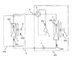
図1は実施の形態1に係る空気調和装置を概略的に示す冷媒回路図である。
図1に示すように、本実施の形態における空気調和装置は、室外機301と、室内機302とを備える。Embodiment 1 FIG.
(Constitution)
FIG. 1 is a refrigerant circuit diagram schematically showing an air conditioner according to Embodiment 1. FIG.
As shown in FIG. 1, the air conditioning apparatus in the present embodiment includes an
この空気調和装置は、蒸気圧縮式の冷凍サイクル運転を行うことによって、屋内の冷暖房に使用される装置である。 This air conditioner is an apparatus used for indoor air conditioning by performing a vapor compression refrigeration cycle operation.
<室内機>
室内機302は、屋内の天井に埋め込みや吊り下げ等により設置され、又は屋内の壁面に壁掛け等により設置され、液接続配管6及びガス接続配管9を介して室外機301に接続されて冷媒回路の一部を構成している。
以下、室内機302の詳細な構成について説明する。<Indoor unit>
The
Hereinafter, a detailed configuration of the
室内機302は、利用側熱交換器である室内熱交換器7と、室内送風機8とを有する。 The
室内熱交換器7は、例えば伝熱管と多数のフィンとにより構成されるクロスフィン式のフィン・アンド・チューブ型熱交換器からなる。
この室内熱交換器7は、冷房運転時には冷媒の蒸発器として機能して室内の空気を冷却し、暖房運転時には冷媒の凝縮器として機能して室内の空気を加熱する。The indoor heat exchanger 7 is composed of, for example, a cross fin type fin-and-tube heat exchanger composed of heat transfer tubes and a large number of fins.
The indoor heat exchanger 7 functions as a refrigerant evaporator during cooling operation to cool indoor air, and functions as a refrigerant condenser during heating operation to heat indoor air.
室内送風機8は、室内熱交換器7に付設され、室内熱交換器7に供給する空気の流量を可変することが可能なファン、例えばDCファンモータ(図示せず)によって駆動される遠心ファンや多翼ファン等からなる。
この室内送風機8は、室内機302内に室内空気を吸入し、室内熱交換器7により冷媒との間で熱交換した空気を供給空気として室内に供給する機能を有する。The indoor blower 8 is attached to the indoor heat exchanger 7, and is a fan capable of varying the flow rate of air supplied to the indoor heat exchanger 7, such as a centrifugal fan driven by a DC fan motor (not shown). Consists of multi-blade fans.
The indoor blower 8 has a function of sucking indoor air into the
また、室内機302には、各種のセンサが設置されている。
すなわち、室内熱交換器7の液側には、液状態又は気液二相状態の冷媒の温度を検出する液側温度センサ205が設けられている。
また、室内熱交換器7には、気液二相状態の冷媒の温度を検出するガス側温度センサ207が設けられている。
さらに、室内機302の室内空気の吸入口側には、当該室内機302内に流入する室内空気の温度(吸込空気温度)を検出する室内温度センサ206が設けられている。Various sensors are installed in the
That is, a liquid
The indoor heat exchanger 7 is provided with a gas
Further, an
なお、室内温度センサ206を、室内機302の室内空気の吹出口側に設けて、室内機302内から吐出する室内空気の温度(吹出空気温度)を検出するようにしても良い。
なお、液側温度センサ205、ガス側温度センサ207、及び室内温度センサ206は、例えばサーミスタにより構成されている。The
In addition, the liquid
室内送風機8は、これらセンサの検出値に応じて運転制御手段100(後述)によって制御される。 The indoor blower 8 is controlled by operation control means 100 (described later) according to the detection values of these sensors.
<室外機>
室外機301は、屋外に設置されており、液接続配管6及びガス接続配管9を介して室内機302に接続されており、冷媒回路の一部を構成している。
以下、室外機301の詳細な構成について説明する。<Outdoor unit>
The
Hereinafter, a detailed configuration of the
室外機301は、圧縮機1と、四方弁2と、熱源側熱交換器としての室外熱交換器3と、室外送風機4と、膨張弁5とを有する。 The
膨張弁5は、室外機301の液側に接続配置されている。
この膨張弁5は、絞り開度が可変であり、冷媒回路内を流れる冷媒の流量の調節等を行う。The
The
圧縮機1は、運転容量を可変することが可能であり、例えばインバータにより制御されるモータ(図示せず)によって駆動される容積式圧縮機を用いる。
この圧縮機1は、制御部101により制御される。
例えば、室内熱交換器7の室内温度センサ206と、後述するリモコン105の設定温度(目標値)との偏差に応じて制御される。The compressor 1 can vary its operating capacity. For example, a positive displacement compressor driven by a motor (not shown) controlled by an inverter is used.
The compressor 1 is controlled by the
For example, it is controlled according to the deviation between the
なお、本実施の形態では、圧縮機1が1台のみの場合を説明するが、これに限定されず、室内機302の接続台数等に応じて、2台以上の圧縮機1が並列に接続されたものであっても良い。 In this embodiment, a case where only one compressor 1 is provided will be described. However, the present invention is not limited to this, and two or more compressors 1 are connected in parallel according to the number of
四方弁2は、冷媒の流れの方向を切り換えるための弁である。
この四方弁2は、冷房運転時には、圧縮機1の吐出側と室外熱交換器3のガス側とを接続するとともに、圧縮機1の吸入側とガス接続配管9側とを接続するように(図1の四方弁2の破線を参照)、冷媒流路を切り換える機能を有する。
これにより、室外熱交換器3を圧縮機1において圧縮される冷媒の凝縮器として、且つ室内熱交換器7を室外熱交換器3において凝縮される冷媒の蒸発器として機能させる。The four-way valve 2 is a valve for switching the direction of the refrigerant flow.
During the cooling operation, the four-way valve 2 connects the discharge side of the compressor 1 and the gas side of the
As a result, the
また四方弁2は、暖房運転時には、圧縮機1の吐出側とガス接続配管9側とを接続するとともに、圧縮機1の吸入側と室外熱交換器3のガス側とを接続するように(図1の四方弁2の実線を参照)、冷媒流路を切り換える機能を有する。
これにより、室内熱交換器7を圧縮機1において圧縮される冷媒の凝縮器として、且つ室外熱交換器3を室内熱交換器7において凝縮される冷媒の蒸発器として機能させる。The four-way valve 2 connects the discharge side of the compressor 1 and the gas connection pipe 9 side during heating operation, and connects the suction side of the compressor 1 and the gas side of the outdoor heat exchanger 3 ( 1 (see the solid line of the four-way valve 2 in FIG. 1), and has a function of switching the refrigerant flow path.
Thus, the indoor heat exchanger 7 is caused to function as a refrigerant condenser to be compressed in the compressor 1, and the
室外熱交換器3は、例えば伝熱管と多数のフィンとにより構成されるクロスフィン式のフィン・アンド・チューブ型熱交換器からなる。
この室外熱交換器3は、そのガス側が四方弁2に接続され、その液側が液接続配管6に接続され、冷房運転時には冷媒の凝縮器として機能し、暖房運転時には冷媒の蒸発器として機能する。The
The
室外送風機4は、室外熱交換器3に付設され、室外熱交換器3に供給する空気の流量を可変することが可能なファン、例えばDCファンモータ(図示せず)によって駆動されるプロペラファンからなる。
この室外送風機4は、室外機301内に室外空気を吸入し、室外熱交換器3により冷媒との間で熱交換した空気を室外に排出する機能を有する。The outdoor blower 4 is attached to the
The outdoor blower 4 has a function of sucking outdoor air into the
また、室外機301には、各種のセンサが設置されている。
すなわち、圧縮機1には、吐出温度を検出する吐出温度センサ201が設けられている。
また、室外熱交換器3には、気液二相状態の冷媒の温度(冷房運転時における凝縮温度又は暖房運転時における蒸発温度)を検出するガス側温度センサ202が設けられている。
さらに、室外熱交換器3の液側には、液状態又は気液二相状態の冷媒の温度を検出する液側温度センサ204が設けられている。
また、室外機301の室外空気の吸入口側には、当該室外機301内に流入する室外空気の温度すなわち外気温度を検出する室外温度センサ203が設けられている。The
That is, the compressor 1 is provided with a
The
Further, a liquid
In addition, an
なお、圧縮機1、四方弁2、室外送風機4、及び膨張弁5は、これらセンサの検出値に応じて運転制御手段100(後述)によって制御される。 The compressor 1, the four-way valve 2, the outdoor blower 4, and the
<制御系>
図2は実施の形態1に係る運転制御手段100の構成を示す図である。
図2に示すように、空気調和装置は、運転制御手段100を備える。
運転制御手段100は、制御部101、測定部103、記憶部104、リモコン105、報知部106を備える。
また、制御部101は、比較部102を有する。<Control system>
FIG. 2 is a diagram illustrating a configuration of the
As shown in FIG. 2, the air conditioner includes an
The
In addition, the
リモコン105は、例えば使用者からの操作に基づいて、室内機302の吹出空気温度の設定値や室内送風機8の設定風量、運転モードなどを設定する。
また、リモコン105は、例えば液晶表示部を有し、制御部101からの情報を受信して当該情報を表示する。The
In addition, the
測定部103は、当該空気調和装置の運転状態データを取得するものである。
測定部103は、運転状態データとして、室外機301に流入する外気温度、室内機302に流入する室内空気温度、運転モード、設定温度、室内送風機8の設定風量、圧縮機1の冷媒吐出温度、圧縮機1の運転容量、及び膨張弁5の開度の少なくとも1つを取得する。
また、測定部103は、上記に加え、運転状態データとして、室外送風機4及び室内送風機8の回転数や、圧縮機1、室外送風機4及び室内送風機8を駆動する駆動モータに供給される電流の少なくとも1つを取得するようにしても良い。
そして、測定部103は、取得した運転データの情報を制御部101に入力する。The
The
Further, in addition to the above, the
Then, the
制御部101は、運転状態データに基づいて、圧縮機1の運転容量、室外送風機4の風量、室内送風機8の風量、及び膨張弁5の開度の少なくとも1つを制御する。
制御部101は、例えばリモコン105から入力された設定温度や設定風量に基づいて、所望の制御目標範囲に収まるように各部を制御する。The
The
また、制御部101は、運転状態データが所定の条件を満たしたとき、当該運転状態データの情報を記憶部104に記憶させる。詳細は後述する。
制御部101の比較部102は、記憶部104に記憶された運転状態データと、現在の運転状態データとを比較して、当該空気調和装置の異常状態又は異常の予兆を検出する。In addition, when the driving state data satisfies a predetermined condition, the
The
記憶部104は、例えばフラッシュメモリなどの記憶装置で構成される。
この記憶部104には、運転状態データが記憶される。
また、記憶部104には、予め、異常状態又は異常の予兆を判断するための、所定の閾値(後述)が記憶される。The
The
In addition, the
報知部106は、例えばブザーやスピーカ、LEDや液晶パネルなどにより構成することができる。
この報知部106は、制御部101からの指示により、異常状態又は異常の予兆を報知する。
なお、報知部106は、本発明における「報知手段」に相当する。The
The
The
以上、本実施の形態における空気調和装置の構成を説明した。
次に、本実施の形態における空気調和装置の動作を説明する。In the above, the structure of the air conditioning apparatus in this Embodiment was demonstrated.
Next, operation | movement of the air conditioning apparatus in this Embodiment is demonstrated.
(動作)
まず、冷房運転及び暖房運転における各部の動作について説明する。(Operation)
First, the operation of each part in the cooling operation and the heating operation will be described.
<冷房運転>
まず、冷房運転について、図1を用いて説明する。<Cooling operation>
First, the cooling operation will be described with reference to FIG.
冷房運転時は、四方弁2が図1の破線で示される状態に設定する。
すなわち、圧縮機1の吐出側が室外熱交換器3のガス側に接続され、且つ、圧縮機1の吸入側が室内熱交換器7のガス側に接続された状態となる。
また、膨張弁5は、圧縮機1の吸入側における冷媒の過熱度が所定値になるように開度調節される。During the cooling operation, the four-way valve 2 is set to a state indicated by a broken line in FIG.
That is, the discharge side of the compressor 1 is connected to the gas side of the
Further, the opening degree of the
圧縮機1の吸入における冷媒の過熱度は、例えば、圧縮機吸入温度より、ガス側温度センサ207により検出される冷媒の蒸発温度を差し引くことによって求められる。
ここで、圧縮機吸入温度は、ガス側温度センサ207により検出される冷媒の蒸発温度を低圧の飽和圧力に換算し、ガス側温度センサ202により検出される冷媒の凝縮温度を高圧の飽和圧力に換算し、圧縮機1の吐出温度センサ201により検出される冷媒の吐出温度より、圧縮機1の圧縮工程はポリトロープ変化と仮定することにより算出することができる。The degree of superheat of the refrigerant in the suction of the compressor 1 is obtained by subtracting the evaporation temperature of the refrigerant detected by the gas
Here, the compressor suction temperature is obtained by converting the refrigerant evaporation temperature detected by the gas
この冷媒回路の状態で、圧縮機1、室外送風機4及び室内送風機8を起動すると、低圧のガス冷媒は、圧縮機1に吸入されて圧縮されて高圧のガス冷媒となる。
その後、高圧のガス冷媒は、四方弁2を経由して室外熱交換器3に送られて、室外送風機4によって供給される室外空気と熱交換を行って凝縮されて高圧の液冷媒となる。When the compressor 1, the outdoor blower 4, and the indoor blower 8 are started in the state of this refrigerant circuit, the low-pressure gas refrigerant is sucked into the compressor 1 and compressed to become a high-pressure gas refrigerant.
Thereafter, the high-pressure gas refrigerant is sent to the
そして、この高圧の液冷媒は、膨張弁5によって減圧されて、低温低圧の気液二相冷媒となり、液接続配管6を経由して室内機302に送られ、室内熱交換器7で室内空気と熱交換を行って蒸発されて低圧のガス冷媒となる。 Then, the high-pressure liquid refrigerant is decompressed by the
ここで、膨張弁5は、圧縮機1の吸入における過熱度が所定値になるように室内熱交換器7内を流れる冷媒の流量を制御しているため、室内熱交換器7において蒸発された低圧のガス冷媒は、所定の過熱度を有する状態となる。
このように、各室内熱交換器7には、室内機302が設置された空調空間において要求される運転負荷に応じた流量の冷媒が流れている。Here, since the
Thus, each indoor heat exchanger 7 is supplied with a refrigerant having a flow rate corresponding to the operation load required in the air-conditioned space in which the
この低圧のガス冷媒は、ガス接続配管9を経由して室外機301に送られ、四方弁2を経由して、再び、圧縮機1に吸入される。 The low-pressure gas refrigerant is sent to the
<暖房運転>
次に、暖房運転について、図1を用いて説明する。<Heating operation>
Next, the heating operation will be described with reference to FIG.
暖房運転時は、四方弁2が図1の実線で示される状態に設定する。
すなわち、圧縮機1の吐出側が室内熱交換器7のガス側に接続され、且つ圧縮機1の吸入側が室外熱交換器3のガス側に接続された状態となる。
また、膨張弁5は圧縮機1の吸入における冷媒の過熱度が所定値になるように開度調節される。During the heating operation, the four-way valve 2 is set to the state shown by the solid line in FIG.
That is, the discharge side of the compressor 1 is connected to the gas side of the indoor heat exchanger 7, and the suction side of the compressor 1 is connected to the gas side of the
The opening degree of the
圧縮機1の吸入における冷媒の過熱度は、例えば、圧縮機吸入温度より、ガス側温度センサ202により検出される冷媒の蒸発温度を差し引くことによって求められる。
ここで、圧縮機吸入温度は、ガス側温度センサ202により検出される冷媒の蒸発温度を低圧の飽和圧力に換算し、ガス側温度センサ207により検出される冷媒の凝縮温度を高圧の飽和圧力に換算し、圧縮機1の吐出温度センサ201により検出される冷媒の吐出温度より、圧縮機1の圧縮工程はポリトロープ変化と過程することにより算出することができる。The degree of superheat of the refrigerant in the suction of the compressor 1 is obtained, for example, by subtracting the evaporation temperature of the refrigerant detected by the gas
Here, the compressor suction temperature is obtained by converting the refrigerant evaporation temperature detected by the gas
この冷媒回路の状態で、圧縮機1、室外送風機4及び室内送風機8を起動すると、低圧のガス冷媒は、圧縮機1に吸入されて圧縮されて高圧のガス冷媒となり、四方弁2及びガス接続配管9を経由して、室内機302に送られる。 When the compressor 1, the outdoor fan 4, and the indoor fan 8 are started in the state of this refrigerant circuit, the low-pressure gas refrigerant is sucked into the compressor 1 and compressed to become a high-pressure gas refrigerant, and the four-way valve 2 and the gas connection It is sent to the
そして、室内機302に送られた高圧のガス冷媒は、室内熱交換器7において、室内空気と熱交換を行って凝縮されて高圧の液冷媒となった後、液接続配管6を経由して、膨張弁5によって減圧されて低圧の気液二相状態の冷媒となる。 The high-pressure gas refrigerant sent to the
ここで、膨張弁5は、圧縮機1の吸入における過熱度が所定値になるように室内熱交換器7内を流れる冷媒の流量を制御しているため、室内熱交換器7において凝縮された高圧の液冷媒は、所定の過冷却度を有する状態となる。
このように、各室内熱交換器7には、各室内機302が設置された空調空間において要求される運転負荷に応じた流量の冷媒が流れている。Here, since the
Thus, each indoor heat exchanger 7 is supplied with a refrigerant having a flow rate corresponding to the operation load required in the air-conditioned space in which each
この低圧の気液二相状態の冷媒は、室外機301の室外熱交換器3に流入する。
そして、室外熱交換器3に流入した低圧の気液二相状態の冷媒は、室外送風機4によって供給される室外空気と熱交換を行って凝縮されて低圧のガス冷媒となり、四方弁2を経由して再び、圧縮機1に吸入される。This low-pressure gas-liquid two-phase refrigerant flows into the
The low-pressure gas-liquid two-phase refrigerant flowing into the
このように、冷房運転及び暖房運転を含む運転処理が運転制御手段100により行われる。 As described above, the
なお、高圧の圧力及び低圧の圧力を算出するのに、ここでは冷媒の凝縮温度及び蒸発温度より換算しているが、図1の構成に加え、圧縮機1の吸入側、吐出側に圧力センサを付加して直接圧力を求めるようにしても良い。 Note that the high pressure and the low pressure are calculated from the condensation temperature and the evaporation temperature of the refrigerant, but in addition to the configuration of FIG. 1, pressure sensors are provided on the suction side and the discharge side of the compressor 1. May be added directly to obtain the pressure.
なお、図1の構成に加え、圧縮機1の吸入側に吸入圧力センサと吸入温度センサとを設け、これらの値から、冷媒の過熱度を検出するようにしても良い。
つまり、吸入圧力センサにより検出される圧縮機1の吸入圧力より、蒸発温度に対応する飽和温度値に換算し、吸入温度センサにより検出される冷媒温度値から、この冷媒の飽和温度値を差し引くことによって冷媒の過熱度を検出する。In addition to the configuration shown in FIG. 1, a suction pressure sensor and a suction temperature sensor may be provided on the suction side of the compressor 1, and the superheat degree of the refrigerant may be detected from these values.
That is, the suction pressure of the compressor 1 detected by the suction pressure sensor is converted into a saturation temperature value corresponding to the evaporation temperature, and the saturation temperature value of the refrigerant is subtracted from the refrigerant temperature value detected by the suction temperature sensor. To detect the degree of superheat of the refrigerant.
<運転状態データの収集>
次に、運転状態データの収集動作について説明する。<Collecting operating status data>
Next, the operation state data collection operation will be described.
図3は実施の形態1に係る運転状態データの収集を説明する図である。
図3においては、空気調和装置が日本国内に設置された場合において、四季を判断して、各季節ごとに行うデータ収集を示している。FIG. 3 is a diagram for explaining collection of operation state data according to the first embodiment.
In FIG. 3, when the air conditioning apparatus is installed in Japan, the four seasons are judged and data collection performed every season is shown.
まず、制御部101は、少なくとも、室外機301に流入する外気温度と、圧縮機1の運転容量と、当該空気調和装置の運転モードとに基づき、当該空気調和装置の設置場所における現在の季節を判断する。
例えば、夏を判断する条件として、外気温が30℃以上、運転モードが「冷房」、圧縮機1の運転が所定時間以上連続で行われた場合、現在の季節が夏であると判断する。
同様に、秋、冬、春を判断する所定の条件に基づいて、現在の季節を判断する。First, the
For example, as conditions for determining summer, when the outside air temperature is 30 ° C. or higher, the operation mode is “cooling”, and the compressor 1 is continuously operated for a predetermined time or more, it is determined that the current season is summer.
Similarly, the current season is determined based on predetermined conditions for determining autumn, winter, and spring.
なお、季節を判断する所定の条件は、上記の運転状態データに限らず、例えば、所定期間における設定温度の平均値や、外気温と設定温度との差など、適宜設定することができる。 The predetermined condition for determining the season is not limited to the above-described operation state data, and can be set as appropriate, for example, an average value of the set temperature in a predetermined period, a difference between the outside air temperature and the set temperature, or the like.
なお、この季節の判断する所定の条件は、当該空気調和装置が設置される場所に応じて、適宜設定することができる。例えば、熱帯気候の地域では、雨季と乾季とを判断するための条件を設定するようにしても良い。 In addition, the predetermined condition judged in this season can be appropriately set according to the place where the air conditioner is installed. For example, in a tropical climate region, conditions for judging the rainy season and the dry season may be set.
次に、制御部101は、記憶部104に当該季節における運転状態データの情報が記憶されていないとき、当該季節を識別する情報と共に、現在の運転状態データの情報を記憶部104に記憶させる。
また、制御部101は、季節のサイクルの経過を判断し、当該サイクルの当該季節における運転状態データの情報が記憶部104に記憶されていないとき、当該サイクル数及び季節を識別する情報と共に、現在の運転状態データの情報を記憶部104に記憶させる。Next, when the information on the driving state data in the season is not stored in the
In addition, the
ここで、季節を識別する情報としては、例えば日本国内においては、春夏秋冬を識別する符号などを設定する。
また、サイクル数を識別する情報として、例えば、経過年を示す数字などを設定する。Here, as information for identifying the season, for example, a code for identifying spring, summer, autumn and winter is set in Japan.
Further, as information for identifying the number of cycles, for example, a number indicating an elapsed year is set.
例えば図3において、当該空気調和装置の運転を開始して、始めて、現在の季節が夏であると判断したとき、制御部101は、記憶部104に、経過年が1年で、季節が夏の識別情報を有する運転状態データが記憶されているかを確認する。
ここでは、当該サイクルの当該季節のデータは記憶されていないので、制御部101は、測定部103により取得された運転状態データの情報を、記憶部104に記憶させる。
このとき、当該運転状態データには、サイクル数が1年目、季節が夏を識別する情報を付加する。
以降、同様に、各年の各季節について運転状態データを収集する。For example, in FIG. 3, when it is determined that the current season is summer for the first time after starting the operation of the air conditioner, the
Here, since the season data of the cycle is not stored, the
At this time, information for identifying the cycle number as the first year and the season as summer is added to the operation state data.
Thereafter, similarly, operation state data is collected for each season of each year.
なお、季節を判断する所定の条件を、同年の同じ季節に複数回満たした場合、代表データのみを記憶するようにしても良い。
例えば、所定の条件を満たしたデータのうち、制御指令値と実績値との差が最も大きい運転状態データを代表データとして記憶するようにしても良い。Note that if the predetermined condition for judging the season is satisfied a plurality of times in the same season of the same year, only representative data may be stored.
For example, among the data satisfying a predetermined condition, the operation state data having the largest difference between the control command value and the actual value may be stored as representative data.
なお、上記の運転状態データ加えて、異常履歴、通信データ等の情報を記憶するようにしても良い。
なお、記憶する運転状態データとしては、当該空気調和装置を構成する部品の交換時期に影響を与えるパラメータのみを記憶するようにしても良い。In addition to the above operating state data, information such as abnormality history and communication data may be stored.
In addition, as the operation state data to be stored, only the parameters that affect the replacement timing of the parts constituting the air conditioner may be stored.
このように、運転状態データの収集は、1年を通じた季節のサイクルにおいて、各季節ごとに収集する。 In this manner, the operation state data is collected for each season in a seasonal cycle throughout the year.
これにより、異常状態又は異常の予兆の検出に必要な、過去の運転データを全て記憶することが無く、記憶部104に記憶する記憶容量を少なくすることが可能となる。 Thereby, it is possible to reduce the storage capacity stored in the
<異常又は予兆の検出>
次に、当該空気調和装置の異常状態又は異常の予兆の検出動作について説明する。<Detection of abnormalities or signs>
Next, an operation for detecting an abnormal state or a sign of abnormality of the air conditioner will be described.
図4は製品寿命末期の故障による事故発生を説明する図である。
図4に示すように、空気調和装置は、経年により、経年劣化に伴う故障や省エネ効率が悪化する(運転状態が悪くなる。)。
このような運転状態の悪化を、未然に予兆することで、製品寿命末期の故障による事故を防ぐことが重要である。
本実施の形態における制御部101は、経年劣化に伴う故障や省エネ効率の悪化が発生し易い状態(以下「異常の予兆」という。)を検出する。
また、制御部101は、経年劣化に伴う故障や省エネ効率の悪化が発生した状態(以下「異常状態」という。)を検出する。FIG. 4 is a diagram for explaining the occurrence of an accident due to a failure at the end of the product life.
As shown in FIG. 4, the air conditioner deteriorates over time due to failure due to aging and energy saving efficiency (operating state deteriorates).
It is important to prevent accidents due to failures at the end of the product life by predicting such deterioration of the operating state.
The
In addition, the
まず、制御部101の比較部102は、記憶部104に記憶された現在の季節に対応する過去の運転状態データと、現在の運転状態データとを比較して、当該空気調和装置の異常状態又は異常の予兆を検出する。 First, the
異常状態の検出においては、制御部101の比較部102は、記憶部104に記憶された運転状態データと、現在の運転状態データとの差が所定の閾値を超えたとき、当該空気調和装置の異常状態を検出する。 In the detection of the abnormal state, the
また、異常の予兆の検出においては、制御部101の比較部102は、現在の運転状態データが正常運転状態の範囲内であって、且つ、記憶部104に記憶された運転状態データと、現在の運転状態データとの差が所定の閾値を超えたとき、異常の予兆を検出する。 In the detection of a sign of abnormality, the
ここで、記憶部104に記憶された運転状態データと、現在の運転状態データとの比較は、例えば、過去の制御指令値と実績値との差と、現在の制御指令値と実績値との差とを比較する。 Here, the comparison between the operation state data stored in the
なお、上記説明では、記憶部104に予め記憶された所定の閾値を用いて、異常状態又は異常の予兆を検出したが、これに限らず、制御部101は、当該空気調和装置の運転時間の積算値を求め、該運転時間の積算値に応じて、所定の閾値を変化させるようにしても良い。 In the above description, an abnormal state or a sign of abnormality is detected using a predetermined threshold stored in advance in the
例えば、予め、記憶部104に、積算時間に対応する閾値のデータをテーブルとして用意しておき、運転積算時間が長くなるにつれて、当該所定の閾値を高く(異常と判断し易い値)にするようにしても良い。 For example, threshold value data corresponding to the accumulated time is prepared as a table in the
<ユーザーへの報知>
次に、異常状態又は異常の予兆の検出結果の報知動作について説明する。<Notification to users>
Next, the notification operation of the detection result of the abnormal state or the sign of abnormality will be described.
制御部101は、上記動作により、異常状態又は異常の予兆を検知したとき、報知部106、及びリモコン105の何れか一方又は両方により、当該異常状態又は異常の予兆を報知させる。 When the
まず、報知部106による報知について説明する。
制御部101は、上記の動作により、異常状態又は異常の予兆を検出したとき、報知部106に、当該異常状態又は異常の予兆を報知させる。
例えば、LEDにより異常状態の場合は赤色を点灯させ、異常の予兆を検出した場合は黄色を点灯させる。また、例えば、当該検出内容の情報を液晶パネルに表示するようにしても良い。また、例えば、異常状態と異常の予兆とで異なるブザー音によりユーザーに報知しても良い。First, notification by the
When the
For example, when an abnormal state is detected by the LED, red is lit, and when an abnormality sign is detected, yellow is lit. Further, for example, information on the detected contents may be displayed on the liquid crystal panel. Further, for example, the user may be notified by a buzzer sound that is different between an abnormal state and a sign of abnormality.
なお、制御部101は、単位期間における当該空気調和装置の運転頻度を検出し、該運転頻度が所定の頻度より少ないとき、異常状態又は異常の予兆を報知部106に報知させるようにしても良い。 Note that the
この運転頻度は、例えば、単位時間当たりのサーモオンオフ時間、サーモオンオフ回数、積算時間、圧縮機1の駆動モータの運転周波数等により、求めることができる。 This operation frequency can be obtained from, for example, the thermo on / off time per unit time, the number of thermo on / off times, the integration time, the operation frequency of the drive motor of the compressor 1, and the like.
このように、当該空気調和装置を利用する頻度が高い時期は報知を行わずに、利用する頻度が低いときに報知を行うことができる。
これにより、運転頻度の低い時期に、例えばメンテナンスや機器の交換を促すことができ、空気調和装置の利用頻度が高い時期に、空調不能となる可能性を減少させ、利用者の利便性、快適性を向上させることができる。Thus, notification can be performed when the frequency of use is low, without performing notification when the frequency of using the air-conditioning apparatus is high.
As a result, for example, maintenance and replacement of equipment can be promoted at a low operating frequency, and the possibility of air conditioning not being possible at a high usage frequency of the air conditioner is reduced. Can be improved.
次に、リモコン105による報知について説明する。
記憶部104には、予め、各種の運転状態データの異常状態に対するユーザーの対処方法、又は異常の予兆に対する運転への影響の情報が設定される。Next, notification by the
The
ここで、異常状態に対するユーザーの対処方法としては、例えば、製品寿命により機器を交換する必要がある旨(買い換え推奨)の情報などを設定する。また、例えば、当該異常を回避する処置内容の情報などを設定する。 Here, as a method for the user to deal with the abnormal state, for example, information indicating that the device needs to be replaced due to the product life (recommendation for replacement) is set. In addition, for example, information on treatment contents for avoiding the abnormality is set.
また、異常の予兆に対する運転への影響としては、例えば、正常運転の範囲内であるものの、冷暖房能力が低下している旨や、省エネ効率が悪化している旨の情報などを設定する。また、買い換え時期が近づいている旨の情報を設定する。 Moreover, as an influence on the driving | operation with respect to the anomaly sign, for example, although it is within the range of the normal driving, information that the cooling / heating capacity is reduced or the energy saving efficiency is deteriorated is set. Also, information indicating that the replacement time is approaching is set.
なお、上記情報に代えて、異常内容に応じたコード番号の情報を記憶するようにしても良い。 Instead of the above information, information of a code number corresponding to the abnormality content may be stored.
制御部101は、上記動作により、異常状態又は異常の予兆を検出したとき、当該異常状態又は異常の予兆を検出した運転状態データに応じて予め設定された所定の情報を、リモコン105に送信する。 When the
リモコン105は、制御部101からの情報を受信して当該情報を、例えば液晶パネルに表示する。 The
なお、異常状態又は異常の予兆を検出した各種の運転状態データのうち、ユーザーに開示する必要がある運転状態データを予め設定して、当該運転状態データの異常状態等のみを報知するようにしても良い。 Of the various operating state data in which an abnormal state or a sign of abnormality is detected, the operating state data that needs to be disclosed to the user is set in advance so that only the abnormal state of the operating state data is notified. Also good.
(効果)
以上のように本実施の形態においては、過去の運転状態データと、現在の運転状態データとを比較して、当該空気調和装置の異常状態又は異常の予兆を検出するので、経年劣化に伴う故障や省エネ効率の悪化が発生した状態や、経年劣化に伴う故障や省エネ効率の悪化が発生し易い状態を検出して、製品寿命末期の故障による事故や省エネ効率の悪化を未然に防ぐことができる。(effect)
As described above, in the present embodiment, the past operation state data and the current operation state data are compared to detect an abnormal state or a sign of abnormality of the air conditioner. It is possible to prevent accidents and deterioration of energy efficiency due to failures at the end of the product life by detecting the situation where deterioration of energy efficiency and energy deterioration, failure due to deterioration over time, and the state where energy efficiency is likely to deteriorate are detected. .
また、当該空気調和装置の設置場所における現在の季節を判断して当該季節を識別する情報と共に、現在の運転状態データの情報を記憶部104に記憶させる。
このため、異常状態又は異常の予兆の検出に必要な、過去の運転データを全て記憶することが無く、記憶部104に記憶する記憶容量を少なくすることが可能となる。In addition, information on the current operation state data is stored in the
For this reason, it is possible to reduce the storage capacity stored in the
また、季節のサイクルの経過を判断し、当該サイクル数及び季節を識別する情報と共に、現在の運転状態データの情報を記憶部104に記憶させる。
このため、各年の各季節ごとに運転状態データを収集し、複数年にわたる運転状態データを収集しつつ、記憶部104に記憶する記憶容量を少なくすることが可能となる。Further, the passage of the seasonal cycle is determined, and information on the current operation state data is stored in the
Therefore, it is possible to reduce the storage capacity stored in the
また、記憶部104に記憶された現在の季節に対応する過去の運転状態データと、現在の運転状態データとを比較して、当該空気調和装置の異常状態又は異常の予兆を検出する。
このため、運転状態が類似する過去の運転状態データと、現在の運転状態データとを比較して、精度良く、異常状態又は異常の予兆を検出することができる。Further, the past operation state data corresponding to the current season stored in the
For this reason, it is possible to accurately detect an abnormal state or a sign of abnormality by comparing past operation state data with similar operation states and current operation state data.
また、運転時間の積算値に応じて、所定の閾値を変化させる。
このため、経年劣化による故障の可能性や省エネ効率の悪化状態を、より精度良く検出することができる。Further, the predetermined threshold value is changed according to the integrated value of the operating time.
For this reason, the possibility of failure due to deterioration over time and the state of deterioration in energy saving efficiency can be detected with higher accuracy.
また、当該空気調和装置の運転頻度が所定の頻度より少ないとき、異常状態又は異常の予兆を報知する。
このため、当該空気調和装置を利用する頻度が高い時期は報知を行わずに、利用する頻度が低いときに報知を行うことができる。
したがって、運転頻度の低い時期に、例えばメンテナンスや機器の交換を促すことができ、空気調和装置の利用頻度が高い時期に、空調不能となる可能性を減少させ、利用者の利便性、快適性を向上させることができる。Further, when the operation frequency of the air conditioner is less than a predetermined frequency, an abnormal state or a sign of abnormality is notified.
For this reason, notification can be performed when the frequency of use is low, without performing notification when the frequency of using the air-conditioning apparatus is high.
Therefore, for example, maintenance and replacement of equipment can be urged at a low operation frequency, and the possibility of being unable to be air-conditioned is reduced at a high use frequency of the air conditioner, thereby improving user convenience and comfort. Can be improved.
また、異常状態又は異常の予兆を検出したとき、当該異常状態又は異常の予兆を検出した運転状態データに応じて予め設定された所定の情報を、リモコン105により報知する。
これにより、異常状態に対するユーザーの対処方法、又は異常の予兆に対する運転への影響の情報を、ユーザーに報知することができる。In addition, when an abnormal state or a sign of abnormality is detected, predetermined information preset according to the operation state data in which the abnormal state or sign of abnormality is detected is notified by the
Thereby, a user's coping method with respect to an abnormal state, or the information of the influence on the driving | operation with respect to the abnormal sign can be alert | reported to a user.
1 圧縮機、2 四方弁、3 室外熱交換器、4 室外送風機、5 膨張弁、6 液接続配管、7 室内熱交換器、8 室内送風機、9 ガス接続配管、100 運転制御手段、101 制御部、102 比較部、103 測定部、104 記憶部、105 リモコン、106 報知部、201 吐出温度センサ、202 ガス側温度センサ、203 室外温度センサ、204 液側温度センサ、205 液側温度センサ、206 室内温度センサ、207 ガス側温度センサ、301 室外機、302 室内機。 DESCRIPTION OF SYMBOLS 1 Compressor, 2 Four way valve, 3 Outdoor heat exchanger, 4 Outdoor fan, 5 Expansion valve, 6 Liquid connection piping, 7 Indoor heat exchanger, 8 Indoor blower, 9 Gas connection piping, 100 Operation control means, 101 Control part , 102 Comparison section, 103 Measurement section, 104 Storage section, 105 Remote control, 106 Notification section, 201 Discharge temperature sensor, 202 Gas side temperature sensor, 203 Outdoor temperature sensor, 204 Liquid side temperature sensor, 205 Liquid side temperature sensor, 206 Indoor Temperature sensor, 207 gas side temperature sensor, 301 outdoor unit, 302 indoor unit.
Claims (11)
Translated fromJapanese当該空気調和装置の運転状態データを取得する測定部と、
前記運転状態データに基づいて、前記圧縮機の運転容量、前記室外送風機の風量、前記室内送風機の風量、及び前記膨張弁の開度の少なくとも1つを制御する制御部と、
前記運転状態データが記憶される記憶部と、
を備え、
前記制御部は、
前記運転状態データが所定の条件を満たしたとき、当該運転状態データの情報を前記記憶部に記憶させ、
前記記憶部に記憶された運転状態データと、現在の運転状態データとを比較して、当該空気調和装置の異常状態又は異常の予兆を検出する
ことを特徴とする空気調和装置。An outdoor unit having a compressor, an expansion valve, a heat source side heat exchanger, and an outdoor fan that blows air to the heat source side heat exchanger, a use side heat exchanger, and a room that sends air to the use side heat exchanger In an air conditioner including an indoor unit having a blower,
A measurement unit for obtaining operation state data of the air conditioner;
Based on the operating state data, a control unit that controls at least one of the operating capacity of the compressor, the air volume of the outdoor fan, the air volume of the indoor fan, and the opening of the expansion valve;
A storage unit for storing the operation state data;
With
The controller is
When the driving state data satisfies a predetermined condition, information on the driving state data is stored in the storage unit,
An air conditioner that compares the operating state data stored in the storage unit with the current operating state data to detect an abnormal state or a sign of abnormality of the air conditioner.
前記室外機に流入する外気温度、前記室内機に流入する室内空気温度、運転モード、設定温度、前記室内送風機の設定風量、前記圧縮機の冷媒吐出温度、前記圧縮機の運転容量、及び前記膨張弁の開度の少なくとも1つを取得する
ことを特徴とする請求項1記載の空気調和装置。The measurement unit, as the operation state data,
Outside air temperature flowing into the outdoor unit, indoor air temperature flowing into the indoor unit, operation mode, set temperature, set air volume of the indoor fan, refrigerant discharge temperature of the compressor, operating capacity of the compressor, and expansion The air conditioning apparatus according to claim 1, wherein at least one of the opening degrees of the valves is acquired.
少なくとも、前記室外機に流入する外気温度と、前記圧縮機の運転容量と、当該空気調和装置の運転モードとに基づき、当該空気調和装置の設置場所における現在の季節を判断し、
前記記憶部に当該季節における運転状態データの情報が記憶されていないとき、当該季節を識別する情報と共に、現在の運転状態データの情報を前記記憶部に記憶させ、
前記記憶部に記憶された現在の季節に対応する過去の運転状態データと、現在の運転状態データとを比較して、当該空気調和装置の異常状態又は異常の予兆を検出する
ことを特徴とする請求項1又は2記載の空気調和装置。The controller is
Based on at least the outside air temperature flowing into the outdoor unit, the operating capacity of the compressor, and the operating mode of the air conditioner, determine the current season at the installation location of the air conditioner,
When the information on the driving state data in the season is not stored in the storage unit, the information on the current driving state data is stored in the storage unit together with the information for identifying the season,
Comparing past operation state data corresponding to the current season stored in the storage unit with current operation state data, an abnormal state of the air conditioner or a sign of abnormality is detected. The air conditioning apparatus according to claim 1 or 2.
前記季節のサイクルの経過を判断し、当該サイクルの当該季節における運転状態データの情報が前記記憶部に記憶されていないとき、当該サイクル数及び季節を識別する情報と共に、現在の運転状態データの情報を前記記憶部に記憶させる
ことを特徴とする請求項3記載の空気調和装置。The controller is
When the progress of the cycle of the season is determined and the information on the driving state data in the season of the cycle is not stored in the storage unit, the information on the current driving state data together with the information identifying the number of cycles and the season Is stored in the storage unit. The air conditioner according to claim 3.
前記記憶部に記憶された運転状態データと、現在の運転状態データとの差が所定の閾値を超えたとき、当該空気調和装置の異常状態を検出する
ことを特徴とする請求項1〜4の何れかに記載の空気調和装置。The controller is
The abnormal state of the said air conditioning apparatus is detected when the difference between the driving | running state data memorize | stored in the said memory | storage part and the present driving | running state data exceeds a predetermined threshold value. The air conditioning apparatus according to any one of the above.
現在の運転状態データが正常運転状態の範囲内であって、且つ、前記記憶部に記憶された運転状態データと、現在の運転状態データとの差が所定の閾値を超えたとき、異常の予兆を検出する
ことを特徴とする請求項1〜5の何れかに記載の空気調和装置。The controller is
When the current operation state data is within the range of the normal operation state and the difference between the operation state data stored in the storage unit and the current operation state data exceeds a predetermined threshold, a sign of abnormality The air conditioner according to any one of claims 1 to 5, wherein the air conditioner is detected.
当該空気調和装置の運転時間の積算値を求め、該運転時間の積算値に応じて、前記所定の閾値を変化させる
ことを特徴とする請求項5又は6記載の空気調和装置。The controller is
The air conditioner according to claim 5 or 6, wherein an integrated value of the operation time of the air conditioner is obtained, and the predetermined threshold value is changed according to the integrated value of the operation time.
ことを特徴とする請求項1〜7の何れかに記載の空気調和装置。The air conditioning apparatus according to any one of claims 1 to 7, further comprising a notification unit that notifies the abnormal state or a sign of abnormality.
単位期間における当該空気調和装置の運転頻度を検出し、該運転頻度が所定の頻度より少ないとき、前記異常状態又は異常の予兆を前記報知手段に報知させる
ことを特徴とする請求項8記載の空気調和装置。The controller is
9. The air according to claim 8, wherein the operation frequency of the air conditioner in a unit period is detected, and when the operation frequency is less than a predetermined frequency, the notification means is notified of the abnormal state or an abnormality sign. Harmony device.
前記制御部は、
前記異常状態又は異常の予兆を検出したとき、当該異常状態又は異常の予兆を検出した運転状態データに応じて予め設定された所定の情報を、前記リモコンに送信する
ことを特徴とする請求項1〜9の何れかに記載の空気調和装置。A remote controller for receiving information from the control unit and displaying the information;
The controller is
2. When the abnormal state or an abnormal sign is detected, predetermined information set in advance according to the operation state data in which the abnormal state or the abnormal sign is detected is transmitted to the remote controller. The air conditioning apparatus in any one of -9.
ことを特徴とする請求項10記載の空気調和装置。The air conditioning apparatus according to claim 10, wherein the predetermined information includes information on a user's coping method with respect to the abnormal state or information on an influence on the operation with respect to the abnormality sign.
Priority Applications (4)
| Application Number | Priority Date | Filing Date | Title |
|---|---|---|---|
| JP2009054969AJP5289109B2 (en) | 2009-03-09 | 2009-03-09 | Air conditioner |
| ES10001671.6TES2671050T3 (en) | 2009-03-09 | 2010-02-18 | Air conditioner |
| EP10001671.6AEP2239518B1 (en) | 2009-03-09 | 2010-02-18 | Air-conditioning apparatus |
| CN2010101297591ACN101858636B (en) | 2009-03-09 | 2010-03-08 | Air-conditioning apparatus |
Applications Claiming Priority (1)
| Application Number | Priority Date | Filing Date | Title |
|---|---|---|---|
| JP2009054969AJP5289109B2 (en) | 2009-03-09 | 2009-03-09 | Air conditioner |
Publications (2)
| Publication Number | Publication Date |
|---|---|
| JP2010210121Atrue JP2010210121A (en) | 2010-09-24 |
| JP5289109B2 JP5289109B2 (en) | 2013-09-11 |
Family
ID=42635053
Family Applications (1)
| Application Number | Title | Priority Date | Filing Date |
|---|---|---|---|
| JP2009054969AExpired - Fee RelatedJP5289109B2 (en) | 2009-03-09 | 2009-03-09 | Air conditioner |
Country Status (4)
| Country | Link |
|---|---|
| EP (1) | EP2239518B1 (en) |
| JP (1) | JP5289109B2 (en) |
| CN (1) | CN101858636B (en) |
| ES (1) | ES2671050T3 (en) |
Cited By (17)
| Publication number | Priority date | Publication date | Assignee | Title |
|---|---|---|---|---|
| WO2012036096A1 (en) | 2010-09-17 | 2012-03-22 | トミー株式会社 | Orthodontic bracket |
| JP2012172930A (en)* | 2011-02-22 | 2012-09-10 | Mitsubishi Electric Corp | Air conditioning facility maintenance system |
| JP2013174385A (en)* | 2012-02-24 | 2013-09-05 | Mitsubishi Electric Corp | Air conditioner system, and remote controller |
| CN104101051A (en)* | 2014-06-24 | 2014-10-15 | 广东美的集团芜湖制冷设备有限公司 | Air conditioner and detection control method and device for abnormal coolant circulation of air conditioner |
| KR20150048509A (en)* | 2013-10-28 | 2015-05-07 | 엘지전자 주식회사 | An air conditioner and a method thereof |
| CN105737337A (en)* | 2016-02-24 | 2016-07-06 | 珠海格力电器股份有限公司 | False-start prevention control method and system for electric heating device and air conditioner control system |
| WO2016189665A1 (en)* | 2015-05-26 | 2016-12-01 | 三菱電機株式会社 | Remote controller for air conditioning system |
| JP2018123998A (en)* | 2017-01-31 | 2018-08-09 | ダイキン工業株式会社 | Air conditioning system |
| JPWO2017212606A1 (en)* | 2016-06-09 | 2019-01-17 | 三菱電機株式会社 | Refrigeration cycle equipment |
| JP2019060600A (en)* | 2019-01-24 | 2019-04-18 | 三菱電機株式会社 | Abnormality detection system, refrigeration cycle device, and abnormality detection method |
| JP2019060601A (en)* | 2019-01-24 | 2019-04-18 | 三菱電機株式会社 | Abnormality detection system, refrigeration cycle device, and abnormality detection method |
| WO2019106808A1 (en)* | 2017-11-30 | 2019-06-06 | 三菱電機株式会社 | Air conditioner |
| CN110081568A (en)* | 2019-05-22 | 2019-08-02 | 广东美的制冷设备有限公司 | Air conditioner and its air conditioning control method, control device and readable storage medium storing program for executing |
| WO2021157105A1 (en)* | 2020-02-05 | 2021-08-12 | 三菱電機株式会社 | Air conditioning system |
| JP2023039078A (en)* | 2021-09-08 | 2023-03-20 | ダイキン工業株式会社 | Abnormality diagnostic system, air conditioner and air conditioning system |
| WO2024154345A1 (en)* | 2023-01-20 | 2024-07-25 | 三菱電機株式会社 | Air conditioning system, processing device, and air conditioner operation state determination method |
| JP7598256B2 (en) | 2021-02-10 | 2024-12-11 | 株式会社Subaru | Engine diagnostic equipment |
Families Citing this family (12)
| Publication number | Priority date | Publication date | Assignee | Title |
|---|---|---|---|---|
| EP2913601A4 (en)* | 2012-10-25 | 2016-07-06 | Mitsubishi Electric Corp | CONTROL SYSTEM |
| US20140163744A1 (en)* | 2012-12-07 | 2014-06-12 | Liebert Corporation | Fault detection in a cooling system with a plurality of identical cooling circuits |
| CN105588298A (en)* | 2015-03-26 | 2016-05-18 | 海信(山东)空调有限公司 | Detection method, device and system for air conditioning equipment |
| JPWO2016174734A1 (en)* | 2015-04-28 | 2017-11-30 | 三菱電機株式会社 | Air conditioner monitoring device and method |
| CN105258230B (en)* | 2015-09-30 | 2017-12-19 | 广东美的制冷设备有限公司 | Window air conditioner and its control method |
| EP3587946B1 (en)* | 2017-02-27 | 2021-09-01 | Mitsubishi Electric Corporation | Air conditioner |
| US10989428B2 (en)* | 2017-03-10 | 2021-04-27 | Hitachi, Ltd. | Performance diagnosis device and performance diagnosis method for air conditioner |
| CN109297134B (en)* | 2018-08-29 | 2020-06-30 | 珠海格力电器股份有限公司 | Overload protection method and device for air conditioner, storage medium and air conditioner |
| JP7395824B2 (en)* | 2019-01-31 | 2023-12-12 | 株式会社富士通ゼネラル | Maintenance timing adjustment device and air conditioning system |
| CN110057027B (en)* | 2019-04-15 | 2021-01-29 | 青岛海尔空调器有限总公司 | Method, device and computer storage medium for monitoring temperature and humidity adjustment equipment |
| CN112834889B (en)* | 2019-11-22 | 2024-07-12 | 上海三菱电机·上菱空调机电器有限公司 | Device and method for predicting life of smoothing capacitor in air conditioner outdoor unit |
| CN112303811B (en)* | 2020-10-27 | 2021-12-14 | 珠海格力电器股份有限公司 | Processing method, device and system for air conditioner operation data, air conditioner and storage medium |
Citations (8)
| Publication number | Priority date | Publication date | Assignee | Title |
|---|---|---|---|---|
| JPH02157561A (en)* | 1988-12-12 | 1990-06-18 | Hitachi Ltd | Air conditioner character display |
| JPH02178558A (en)* | 1988-12-28 | 1990-07-11 | Toshiba Corp | Fan motor control device |
| JPH07217964A (en)* | 1994-02-01 | 1995-08-18 | Hitachi Ltd | Air conditioner failure diagnosis system |
| JP2000186849A (en)* | 1998-12-22 | 2000-07-04 | Sharp Corp | Air conditioner |
| JP2002061995A (en)* | 2000-08-16 | 2002-02-28 | Fujitsu General Ltd | Method and apparatus for controlling air conditioner |
| JP2006046762A (en)* | 2004-08-03 | 2006-02-16 | Toho Gas Co Ltd | GHP failure prediction diagnosis method and apparatus |
| JP2006338186A (en)* | 2005-05-31 | 2006-12-14 | Aichi Tokei Denki Co Ltd | Remote monitoring system for operating equipment |
| JP2008249234A (en)* | 2007-03-30 | 2008-10-16 | Mitsubishi Electric Corp | Failure diagnosis device for refrigeration cycle apparatus and refrigeration cycle apparatus equipped with the same |
Family Cites Families (15)
| Publication number | Priority date | Publication date | Assignee | Title |
|---|---|---|---|---|
| US4798055A (en)* | 1987-10-28 | 1989-01-17 | Kent-Moore Corporation | Refrigeration system analyzer |
| US5203179A (en)* | 1992-03-04 | 1993-04-20 | Ecoair Corporation | Control system for an air conditioning/refrigeration system |
| US6332362B1 (en)* | 2000-04-18 | 2001-12-25 | Lg Electronics Inc. | Device and method for detecting anomaly of air conditioner by using acoustic emission method |
| US6324854B1 (en)* | 2000-11-22 | 2001-12-04 | Copeland Corporation | Air-conditioning servicing system and method |
| JP2003172578A (en)* | 2001-12-07 | 2003-06-20 | Hitachi Ltd | Network compatible home appliances, home appliance inspection system and home appliance inspection service |
| JP4288928B2 (en)* | 2002-11-06 | 2009-07-01 | ダイキン工業株式会社 | Air conditioner |
| JP2004301436A (en)* | 2003-03-31 | 2004-10-28 | Mitsubishi Electric Corp | HVAC equipment and HVAC management system |
| JP2004340549A (en) | 2003-05-19 | 2004-12-02 | Daikin Ind Ltd | Component replacement time prediction device, component replacement time prediction method, and component replacement time prediction system |
| JP4523803B2 (en)* | 2004-06-30 | 2010-08-11 | 富士通株式会社 | Fan system, fan device, and fan device control method |
| US7987679B2 (en)* | 2005-02-24 | 2011-08-02 | Mitsubishi Denki Kabushiki Kaisha | Air conditioning apparatus |
| JP2006343063A (en) | 2005-06-10 | 2006-12-21 | Daikin Ind Ltd | Equipment equipment abnormality prediction system, equipment equipment abnormality prediction apparatus, and equipment equipment abnormality prediction method |
| CN101086359A (en)* | 2006-06-06 | 2007-12-12 | 乐金电子(天津)电器有限公司 | Air conditioner and control method thereof |
| JP4151713B2 (en)* | 2006-07-03 | 2008-09-17 | ダイキン工業株式会社 | Control device |
| JP4567637B2 (en)* | 2006-07-10 | 2010-10-20 | ダイキン工業株式会社 | Air conditioning controller |
| KR20080042397A (en)* | 2006-11-09 | 2008-05-15 | 삼성전자주식회사 | Operation system of air conditioning system and its control method |
- 2009
- 2009-03-09JPJP2009054969Apatent/JP5289109B2/ennot_activeExpired - Fee Related
- 2010
- 2010-02-18ESES10001671.6Tpatent/ES2671050T3/enactiveActive
- 2010-02-18EPEP10001671.6Apatent/EP2239518B1/ennot_activeNot-in-force
- 2010-03-08CNCN2010101297591Apatent/CN101858636B/ennot_activeExpired - Fee Related
Patent Citations (8)
| Publication number | Priority date | Publication date | Assignee | Title |
|---|---|---|---|---|
| JPH02157561A (en)* | 1988-12-12 | 1990-06-18 | Hitachi Ltd | Air conditioner character display |
| JPH02178558A (en)* | 1988-12-28 | 1990-07-11 | Toshiba Corp | Fan motor control device |
| JPH07217964A (en)* | 1994-02-01 | 1995-08-18 | Hitachi Ltd | Air conditioner failure diagnosis system |
| JP2000186849A (en)* | 1998-12-22 | 2000-07-04 | Sharp Corp | Air conditioner |
| JP2002061995A (en)* | 2000-08-16 | 2002-02-28 | Fujitsu General Ltd | Method and apparatus for controlling air conditioner |
| JP2006046762A (en)* | 2004-08-03 | 2006-02-16 | Toho Gas Co Ltd | GHP failure prediction diagnosis method and apparatus |
| JP2006338186A (en)* | 2005-05-31 | 2006-12-14 | Aichi Tokei Denki Co Ltd | Remote monitoring system for operating equipment |
| JP2008249234A (en)* | 2007-03-30 | 2008-10-16 | Mitsubishi Electric Corp | Failure diagnosis device for refrigeration cycle apparatus and refrigeration cycle apparatus equipped with the same |
Cited By (27)
| Publication number | Priority date | Publication date | Assignee | Title |
|---|---|---|---|---|
| WO2012036096A1 (en) | 2010-09-17 | 2012-03-22 | トミー株式会社 | Orthodontic bracket |
| JP2012172930A (en)* | 2011-02-22 | 2012-09-10 | Mitsubishi Electric Corp | Air conditioning facility maintenance system |
| JP2013174385A (en)* | 2012-02-24 | 2013-09-05 | Mitsubishi Electric Corp | Air conditioner system, and remote controller |
| KR20150048509A (en)* | 2013-10-28 | 2015-05-07 | 엘지전자 주식회사 | An air conditioner and a method thereof |
| KR102122248B1 (en)* | 2013-10-28 | 2020-06-12 | 엘지전자 주식회사 | An air conditioner and a method thereof |
| CN104101051B (en)* | 2014-06-24 | 2017-01-18 | 广东美的集团芜湖制冷设备有限公司 | Air conditioner and detection control method and device for abnormal coolant circulation of air conditioner |
| CN104101051A (en)* | 2014-06-24 | 2014-10-15 | 广东美的集团芜湖制冷设备有限公司 | Air conditioner and detection control method and device for abnormal coolant circulation of air conditioner |
| WO2016189665A1 (en)* | 2015-05-26 | 2016-12-01 | 三菱電機株式会社 | Remote controller for air conditioning system |
| JPWO2016189665A1 (en)* | 2015-05-26 | 2017-08-10 | 三菱電機株式会社 | Remote controller for air conditioning system |
| CN108307650A (en)* | 2015-05-26 | 2018-07-20 | 三菱电机株式会社 | Remote controllers for air conditioning systems |
| US10365002B2 (en) | 2015-05-26 | 2019-07-30 | Mitsubishi Electric Corporation | Remote controller of air-conditioning system |
| CN105737337B (en)* | 2016-02-24 | 2018-11-30 | 珠海格力电器股份有限公司 | False-start prevention control method and system for electric heating device and air conditioner control system |
| CN105737337A (en)* | 2016-02-24 | 2016-07-06 | 珠海格力电器股份有限公司 | False-start prevention control method and system for electric heating device and air conditioner control system |
| JPWO2017212606A1 (en)* | 2016-06-09 | 2019-01-17 | 三菱電機株式会社 | Refrigeration cycle equipment |
| JP2018123998A (en)* | 2017-01-31 | 2018-08-09 | ダイキン工業株式会社 | Air conditioning system |
| WO2019106808A1 (en)* | 2017-11-30 | 2019-06-06 | 三菱電機株式会社 | Air conditioner |
| JPWO2019106808A1 (en)* | 2017-11-30 | 2020-04-02 | 三菱電機株式会社 | Air conditioner |
| JP2019060600A (en)* | 2019-01-24 | 2019-04-18 | 三菱電機株式会社 | Abnormality detection system, refrigeration cycle device, and abnormality detection method |
| JP2019060601A (en)* | 2019-01-24 | 2019-04-18 | 三菱電機株式会社 | Abnormality detection system, refrigeration cycle device, and abnormality detection method |
| CN110081568B (en)* | 2019-05-22 | 2021-05-28 | 广东美的制冷设备有限公司 | Air conditioner, air conditioner control method and device and readable storage medium |
| CN110081568A (en)* | 2019-05-22 | 2019-08-02 | 广东美的制冷设备有限公司 | Air conditioner and its air conditioning control method, control device and readable storage medium storing program for executing |
| WO2021157105A1 (en)* | 2020-02-05 | 2021-08-12 | 三菱電機株式会社 | Air conditioning system |
| JP2021124241A (en)* | 2020-02-05 | 2021-08-30 | 三菱電機株式会社 | Air conditioning system |
| JP7598256B2 (en) | 2021-02-10 | 2024-12-11 | 株式会社Subaru | Engine diagnostic equipment |
| JP2023039078A (en)* | 2021-09-08 | 2023-03-20 | ダイキン工業株式会社 | Abnormality diagnostic system, air conditioner and air conditioning system |
| JP7513906B2 (en) | 2021-09-08 | 2024-07-10 | ダイキン工業株式会社 | Abnormality diagnosis system, air conditioner, and air conditioning system |
| WO2024154345A1 (en)* | 2023-01-20 | 2024-07-25 | 三菱電機株式会社 | Air conditioning system, processing device, and air conditioner operation state determination method |
Also Published As
| Publication number | Publication date |
|---|---|
| CN101858636A (en) | 2010-10-13 |
| CN101858636B (en) | 2013-04-03 |
| EP2239518B1 (en) | 2018-05-02 |
| JP5289109B2 (en) | 2013-09-11 |
| EP2239518A2 (en) | 2010-10-13 |
| EP2239518A3 (en) | 2014-01-15 |
| ES2671050T3 (en) | 2018-06-04 |
Similar Documents
| Publication | Publication Date | Title |
|---|---|---|
| JP5289109B2 (en) | Air conditioner | |
| KR102295969B1 (en) | Air-conditioner and method for thereof | |
| CN103216908B (en) | Control method for outdoor fan in refrigeration of variable frequency multi-split air-conditioning unit | |
| JP5642227B2 (en) | Air conditioner and air conditioner monitoring system | |
| JP2010127568A (en) | Abnormality detection device and refrigerating cycle device including the same | |
| JP5744081B2 (en) | Air conditioner | |
| JP2008202908A (en) | Air conditioner | |
| CN107208953B (en) | refrigeration unit | |
| JP2010096474A (en) | Air-conditioning control device and air conditioning system | |
| KR20110001667A (en) | Air conditioner and its operation method | |
| JP2015212594A (en) | Compressor deterioration diagnosis method and refrigeration cycle apparatus having the deterioration diagnosis method | |
| JP6141217B2 (en) | Compressor deterioration diagnosis device and compressor deterioration diagnosis method | |
| CN113574326B (en) | Device evaluation system and device evaluation method | |
| JP2010007996A (en) | Trial operation method of air conditioner and air conditioner | |
| CN116194718B (en) | Method for detecting refrigerant leakage, air conditioner, and storage medium | |
| JP2002147905A (en) | Refrigeration equipment | |
| KR101153421B1 (en) | Condensation volume control method for air conditioner | |
| JP2020091080A (en) | Refrigeration cycle device | |
| WO2020003529A1 (en) | Air conditioning system, air conditioning method, and program | |
| KR102470369B1 (en) | Air-conditioner and the method for the same | |
| JP2010210222A (en) | Air conditioner and its control method | |
| JP2009041831A (en) | Multi-room air conditioner | |
| JP2017120141A (en) | Air conditioner and defrost auxiliary device | |
| JP6444536B2 (en) | Compressor deterioration diagnosis device and compressor deterioration diagnosis method | |
| EP4624822A1 (en) | Air conditioner |
Legal Events
| Date | Code | Title | Description |
|---|---|---|---|
| A621 | Written request for application examination | Free format text:JAPANESE INTERMEDIATE CODE: A621 Effective date:20110708 | |
| A977 | Report on retrieval | Free format text:JAPANESE INTERMEDIATE CODE: A971007 Effective date:20121115 | |
| A131 | Notification of reasons for refusal | Free format text:JAPANESE INTERMEDIATE CODE: A131 Effective date:20121120 | |
| A521 | Request for written amendment filed | Free format text:JAPANESE INTERMEDIATE CODE: A523 Effective date:20121225 | |
| TRDD | Decision of grant or rejection written | ||
| A01 | Written decision to grant a patent or to grant a registration (utility model) | Free format text:JAPANESE INTERMEDIATE CODE: A01 Effective date:20130507 | |
| A61 | First payment of annual fees (during grant procedure) | Free format text:JAPANESE INTERMEDIATE CODE: A61 Effective date:20130604 | |
| R150 | Certificate of patent or registration of utility model | Ref document number:5289109 Country of ref document:JP Free format text:JAPANESE INTERMEDIATE CODE: R150 | |
| R250 | Receipt of annual fees | Free format text:JAPANESE INTERMEDIATE CODE: R250 | |
| R250 | Receipt of annual fees | Free format text:JAPANESE INTERMEDIATE CODE: R250 | |
| R250 | Receipt of annual fees | Free format text:JAPANESE INTERMEDIATE CODE: R250 | |
| R250 | Receipt of annual fees | Free format text:JAPANESE INTERMEDIATE CODE: R250 | |
| R250 | Receipt of annual fees | Free format text:JAPANESE INTERMEDIATE CODE: R250 | |
| LAPS | Cancellation because of no payment of annual fees |