JP2010209843A - Control device for internal combustion engine - Google Patents
Control device for internal combustion engineDownload PDFInfo
- Publication number
- JP2010209843A JP2010209843AJP2009058382AJP2009058382AJP2010209843AJP 2010209843 AJP2010209843 AJP 2010209843AJP 2009058382 AJP2009058382 AJP 2009058382AJP 2009058382 AJP2009058382 AJP 2009058382AJP 2010209843 AJP2010209843 AJP 2010209843A
- Authority
- JP
- Japan
- Prior art keywords
- flow rate
- fuel
- gas flow
- reducing gas
- internal combustion
- Prior art date
- Legal status (The legal status is an assumption and is not a legal conclusion. Google has not performed a legal analysis and makes no representation as to the accuracy of the status listed.)
- Pending
Links
Images


Classifications
- Y—GENERAL TAGGING OF NEW TECHNOLOGICAL DEVELOPMENTS; GENERAL TAGGING OF CROSS-SECTIONAL TECHNOLOGIES SPANNING OVER SEVERAL SECTIONS OF THE IPC; TECHNICAL SUBJECTS COVERED BY FORMER USPC CROSS-REFERENCE ART COLLECTIONS [XRACs] AND DIGESTS
- Y02—TECHNOLOGIES OR APPLICATIONS FOR MITIGATION OR ADAPTATION AGAINST CLIMATE CHANGE
- Y02T—CLIMATE CHANGE MITIGATION TECHNOLOGIES RELATED TO TRANSPORTATION
- Y02T10/00—Road transport of goods or passengers
- Y02T10/10—Internal combustion engine [ICE] based vehicles
- Y02T10/30—Use of alternative fuels, e.g. biofuels
Landscapes
- Lubrication Details And Ventilation Of Internal Combustion Engines (AREA)
- Output Control And Ontrol Of Special Type Engine (AREA)
- Electrical Control Of Air Or Fuel Supplied To Internal-Combustion Engine (AREA)
- Combined Controls Of Internal Combustion Engines (AREA)
Abstract
Description
Translated fromJapanese本発明は、内燃機関の制御装置に関する。 The present invention relates to a control device for an internal combustion engine.
燃焼室に燃料を直接噴射する直噴式の内燃機関は、特に、ピストンとシリンダ壁面との隙間が大きい冷間運転時に、噴射によりシリンダ壁面等に付着した燃料の一部が壁面を伝わってエンジンオイルに入り込むことが知られている。
また、内燃機関は、ピストンとシリンダ壁面との隙間を通過してブローバイガス(未燃焼の混合気)が燃焼室からクランク室内に漏出することが知られている。そして、ブローバイガス中に含まれる燃料成分の一部がエンジンオイルに入り込むことで、エンジンオイルを劣化させたり、内燃機関の金属表面を腐食させたりする。そのため、クランク室内に漏出したブローバイガスをPCV(Positive Crankcase Ventilation)によって吸気通路に還元させて再び燃焼室へ導入させる制御が広く行われている。Direct-injection internal combustion engines that inject fuel directly into the combustion chamber, especially during cold operation where the gap between the piston and the cylinder wall surface is large, part of the fuel adhering to the cylinder wall surface due to the injection travels through the wall surface to cause engine oil It is known to get in.
Further, it is known that the internal combustion engine passes through the gap between the piston and the cylinder wall surface, and blow-by gas (unburned mixture) leaks from the combustion chamber into the crank chamber. A part of the fuel component contained in the blow-by gas enters the engine oil, thereby deteriorating the engine oil or corroding the metal surface of the internal combustion engine. For this reason, control is widely performed in which the blow-by gas leaked into the crank chamber is reduced to the intake passage by PCV (Positive Crankcase Ventilation) and introduced into the combustion chamber again.
近年、大気汚染や原油事情の変動に伴い、ガソリン燃料に加えて代替燃料としてのアルコールを同時に使用可能なシステムが実用化されている。このシステムを搭載したFFV(Flexible Fuel Vehicle)では、ガソリン燃料のみならず、ガソリンとアルコールとを任意の割合で混合した燃料で走行することができる。
ガソリンとアルコールとを任意の割合で混合した燃料を使用する場合、ガソリン100%燃料よりも燃料噴射期間が長くなるために、より多くのブローバイガスや筒内付着燃料がクランクケース内に侵入する。よって、ガソリン100%燃料よりも多量の燃料がエンジンオイルに入り込むことになる。In recent years, a system that can simultaneously use alcohol as an alternative fuel in addition to gasoline fuel has been put into practical use due to changes in air pollution and crude oil circumstances. An FFV (Flexible Fuel Vehicle) equipped with this system can run not only with gasoline fuel but also with fuel in which gasoline and alcohol are mixed at an arbitrary ratio.
When a fuel in which gasoline and alcohol are mixed at an arbitrary ratio is used, the fuel injection period is longer than that of
エンジンオイルに入り込んだ燃料は、内燃機関が暖機された際に気化し、PCVを通じて吸気通路へと供給される。特に、FFVの内燃機関の場合、エンジンオイルに多量に入り込んだアルコールが所定温度を超えると爆発的に気化して吸気通路へ供給されるために、内燃機関の空燃比が大きく乱れる。この場合、乱れた空燃比を修正するために燃料噴射量を補正するフィードバック(以下、F/Bと略記する)制御が実行される。しかしながら、PCVを通じて吸気通路に供給されるアルコール量がF/B制御の範囲を超えてしまうと空燃比がオーバーリッチとなり、内燃機関の回転数が急激に変動したり排気エミッションが悪化したりする、といった問題がある。 The fuel that has entered the engine oil is vaporized when the internal combustion engine is warmed up, and is supplied to the intake passage through the PCV. In particular, in the case of an FFV internal combustion engine, if the alcohol that has entered a large amount of engine oil exceeds a predetermined temperature, it is vaporized explosively and supplied to the intake passage, so that the air-fuel ratio of the internal combustion engine is greatly disturbed. In this case, feedback (hereinafter abbreviated as F / B) control for correcting the fuel injection amount is performed to correct the disturbed air-fuel ratio. However, if the amount of alcohol supplied to the intake passage through the PCV exceeds the range of the F / B control, the air-fuel ratio becomes overrich, and the rotational speed of the internal combustion engine suddenly fluctuates or exhaust emission deteriorates. There is a problem.
このような問題を解決するために、PCVガスのアルコール量と、運転状態に応じて定まるブローバイガス中に含まれるエタノール量とに基づきエンジンオイルから蒸発するエタノール量を算出する技術が特許文献1に開示されている。
また、ブローバイガスと外気とを混合すると共に、吸気通路へ還元させるブローバイガスの流量制御を行うことにより、ブローバイガス流入による空燃比の乱れを抑制する技術が特許文献2に開示されている。In order to solve such a problem, Patent Document 1 discloses a technique for calculating the amount of ethanol evaporated from engine oil based on the amount of alcohol in PCV gas and the amount of ethanol contained in blow-by gas determined according to the operating state. It is disclosed.
Japanese Patent Application Laid-Open No. 2004-228688 discloses a technique for suppressing disturbance of an air-fuel ratio due to inflow of blowby gas by mixing blowby gas and outside air and controlling the flow rate of blowby gas to be reduced to the intake passage.
車両に搭載される内燃機関は、自己の故障を診断するOBD(On Board Diagnosis)システムを備えている。OBDシステムは、内燃機関に異常や故障を発見すると異常部分に対応する異常表示灯(Malfunction Indicator Light,以下、MILと略記する)を点灯させることでユーザへ異常を通知する。そして、OBDシステムは、燃料噴射量のズレ、すなわち燃料噴射量の補正量が所定量を超える場合に、燃料噴射系に異常が発生したと診断する。この場合、FFVの内燃機関は、PCVを通じて多量のアルコールが吸気通路に供給されて空燃比が大きく乱れると、燃料噴射量の補正量が所定量を超えてしまうことでOBDシステムが異常と診断する場合がある。そのため、燃料噴射系が正常に稼動しているにも関わらず燃料噴射系異常のMILを点灯させてしまう、といった問題点がある。
しかしながら、特許文献1の技術では、PCVを通じて吸気通路へ過剰なアルコールが供給された際のOBDシステム誤診断に対する対策が設けられていないために、MILの誤点灯を適切に抑制することができない、といった問題点がある。また、特許文献2の技術では、燃料中のアルコール含有率に応じてPCV還元ガス流量を調節することが困難であるために、MILの誤点灯を適切に抑制することができない、といった問題点がある。An internal combustion engine mounted on a vehicle includes an OBD (On Board Diagnosis) system that diagnoses its own failure. When an abnormality or failure is detected in the internal combustion engine, the OBD system notifies the user of the abnormality by turning on an abnormality indicator light (hereinafter, abbreviated as MIL) corresponding to the abnormal part. The OBD system diagnoses that an abnormality has occurred in the fuel injection system when the deviation of the fuel injection amount, that is, the correction amount of the fuel injection amount exceeds a predetermined amount. In this case, when a large amount of alcohol is supplied to the intake passage through the PCV and the air-fuel ratio is greatly disturbed, the FFV internal combustion engine diagnoses the OBD system as abnormal because the correction amount of the fuel injection amount exceeds a predetermined amount. There is a case. For this reason, there is a problem that the MIL of the fuel injection system is turned on even though the fuel injection system is operating normally.
However, in the technique of Patent Document 1, since there is no countermeasure against an OBD system misdiagnosis when excessive alcohol is supplied to the intake passage through the PCV, it is not possible to appropriately suppress the erroneous lighting of the MIL. There is a problem. Further, in the technique of Patent Document 2, since it is difficult to adjust the PCV reducing gas flow rate in accordance with the alcohol content in the fuel, there is a problem that it is not possible to appropriately suppress the MIL erroneous lighting. is there.
本発明は、かかる点に鑑みてなされたものであり、アルコールとガソリンとを任意の割合で混合した燃料を使用可能な内燃機関のOBDシステムのMIL誤点灯の頻度を低減させることができる内燃機関の制御装置を提供することを目的とする。 The present invention has been made in view of the above points, and is an internal combustion engine capable of reducing the frequency of MIL erroneous lighting of an OBD system of an internal combustion engine that can use a fuel in which alcohol and gasoline are mixed at an arbitrary ratio. An object of the present invention is to provide a control device.
上記目的を達成するために、本発明の内燃機関の制御装置は、内燃機関の燃焼室から漏出したブローバイガスを還元通路を通じて吸気通路に還元可能に構成され、かつアルコールとガソリンとを任意の割合で混合した燃料を使用可能な内燃機関の制御装置であって、前記燃料中のアルコール含有率を検出するアルコール含有率検出手段と、前記アルコール含有率検出手段の検出結果に基づいて、前記内燃機関の各運転状態における燃料噴射量の補正量を決定する燃料噴射量補正量決定手段と、前記燃料噴射量補正量決定手段により決定された補正量に基づいて、前記還元通路を通じて吸気通路に還元させるガス流量を決定する還元ガス流量決定手段と、前記還元ガス流量決定手段の決定結果に基づいて、前記ガス流量を調節する還元ガス流量調節手段と、前記還元ガス流量決定手段により決定されたガス流量が、前記還元ガス流量調節手段が調節可能なガス流量より小さい場合に、前記内燃機関の自己故障診断システムが燃料噴射系の異常をユーザに通知することを許可する許可手段と、を備えることを特徴とする。 In order to achieve the above object, the control device for an internal combustion engine of the present invention is configured so that blowby gas leaked from the combustion chamber of the internal combustion engine can be reduced to the intake passage through the reduction passage, and alcohol and gasoline are in any ratio. A control device for an internal combustion engine capable of using the fuel mixed in step (b), the alcohol content rate detecting means for detecting the alcohol content rate in the fuel, and the internal combustion engine based on the detection result of the alcohol content rate detecting means Based on the fuel injection amount correction amount determining means for determining the correction amount of the fuel injection amount in each of the operating states and the correction amount determined by the fuel injection amount correction amount determining means, the fuel is reduced to the intake passage through the reduction passage. A reducing gas flow rate determining means for determining a gas flow rate, and a reducing gas flow rate for adjusting the gas flow rate based on a determination result of the reducing gas flow rate determining means. And when the gas flow rate determined by the reducing gas flow rate determining unit is smaller than the gas flow rate adjustable by the reducing gas flow rate adjusting unit, the internal combustion engine self-failure diagnosis system detects an abnormality in the fuel injection system. Permission means for permitting notification to the user.
特に、本発明の内燃機関の制御装置は、前記内燃機関が使用中の燃料と同一規格の燃料の給油を抑制するようユーザに報知する報知手段を備え、前記報知手段が、前記還元ガス流量調節手段がガス流量を最小に調節する時間が第1しきい値を超える場合に、ユーザに報知することを特徴とすることができる。 In particular, the control device for an internal combustion engine according to the present invention includes notification means for notifying a user to suppress fuel supply of the same standard as the fuel being used by the internal combustion engine, and the notification means adjusts the reducing gas flow rate. If the time for the means to adjust the gas flow rate to the minimum exceeds the first threshold value, the user can be notified.
本発明の内燃機関の制御装置によれば、燃料中のアルコール含有率から燃料噴射量の補正量を決定し、決定した補正量に基づきPCV還元ガス流量を決定し、決定したPCV還元ガス流量が調節可能な流量よりも小さいときに、自己故障診断システムが燃料噴射系の異常をユーザに通知することを許可することができる。よって、アルコールとガソリンとを任意の割合で混合した燃料を使用可能な内燃機関のOBDシステムのMIL誤点灯の頻度を低減させることができる。 According to the control apparatus for an internal combustion engine of the present invention, the correction amount of the fuel injection amount is determined from the alcohol content in the fuel, the PCV reducing gas flow rate is determined based on the determined correction amount, and the determined PCV reducing gas flow rate is When the flow rate is less than the adjustable flow rate, the self-fault diagnosis system can be allowed to notify the user of an abnormality in the fuel injection system. Therefore, it is possible to reduce the frequency of MIL erroneous lighting of an OBD system of an internal combustion engine that can use a fuel in which alcohol and gasoline are mixed at an arbitrary ratio.
また、本発明の内燃機関の制御装置によれば、内燃機関が使用中の燃料によってPCV還元ガス流量を最小に調節する時間が所定時間を超える場合に、使用中の燃料と同一規格の燃料の給油を抑制するようユーザに報知することができる。よって、アルコール含有率の高い燃料の給油を抑制し、エンジンオイルからの過剰なアルコール気化を抑制することで、OBDシステムのMIL誤点灯の頻度を低減させることができる。 Further, according to the control apparatus for an internal combustion engine of the present invention, when the time during which the internal combustion engine adjusts the PCV reducing gas flow rate to the minimum with the fuel being used exceeds a predetermined time, the fuel of the same standard as the fuel being used is used. It is possible to notify the user to suppress refueling. Therefore, it is possible to reduce the frequency of MIL erroneous lighting of the OBD system by suppressing fuel supply with a high alcohol content rate and suppressing excessive alcohol vaporization from the engine oil.
以下、本発明を実施するための形態を図面と共に詳細に説明する。 DESCRIPTION OF EMBODIMENTS Hereinafter, embodiments for implementing the present invention will be described in detail with reference to the drawings.
本発明の実施例1について図面を参照しつつ説明する。図1は、本発明の内燃機関の制御装置を組み込んだ車両制御システム1の概略構成を示した構成図である。なお、図1にはエンジンの1気筒の構成のみを示している。 Embodiment 1 of the present invention will be described with reference to the drawings. FIG. 1 is a configuration diagram showing a schematic configuration of a vehicle control system 1 incorporating a control device for an internal combustion engine of the present invention. FIG. 1 shows only the configuration of one cylinder of the engine.
図1に示す車両制御システム1は、動力源であるエンジン100を備えており、エンジン100の運転動作を総括的に制御するエンジンECU(Electronic Control Unit)10を備えている。また、車両制御システム1は、燃焼室から漏出したブローバイガスを吸気通路へ還流させるPCV通路29、およびPCV通路29を通過する還元ガス流量を調節するPCVバルブ30を備えている。 A vehicle control system 1 shown in FIG. 1 includes an
エンジン100は、車両に搭載される多気筒エンジンであって、各気筒は燃焼室11aを構成するピストン11を備えている。各燃焼室のピストン11はそれぞれコネクティングロッドを介して出力軸であるクランクシャフト12の軸に連結されており、ピストン11の往復運動がコネクティングロッドによってクランクシャフト12の回転へと変換される。 The
クランクシャフト12の軸の近傍には、クランク角センサ31が設けられている。クランク角センサ31は、クランクシャフト12軸の回転角度を検出するように構成されており、検出結果をエンジンECU10に送信する。それにより、エンジンECU10は、運転時のエンジン回転数や回転角速度など、クランク角に関する情報を取得する。 A
各気筒の燃焼室11aには、それぞれ燃焼室11aと連通する吸気ポート13と、吸気ポート13に連結し、吸入空気を吸気ポート13から燃焼室11aへと導く吸気通路14とが接続されている。更に、燃焼室11aの各気筒には、それぞれ燃焼室11aと連通する排気ポート15と、燃焼室11aで発生した排気ガスをエンジン外へと導く排気通路16が接続されている。また、各気筒に接続された排気通路16は、下流側で合流して一本の合流排気通路17となる。 Connected to the
各気筒の燃焼室11aの吸気通路、排気通路に対応して複数の吸気弁、排気弁が設けられている。図1には吸気通路、排気通路と吸気弁、排気弁をそれぞれ1つずつ示している。燃焼室11aの各吸気ポート13には、それぞれ吸気弁18が配置されており、吸気弁18を開閉駆動させるための吸気カムシャフト20が配置されている。更に、燃焼室11aの各排気ポート15には、それぞれ排気弁19が配置されており、排気弁19を開閉駆動させるための排気カムシャフト21が配置されている。 A plurality of intake valves and exhaust valves are provided corresponding to the intake passage and the exhaust passage of the
吸気弁18および排気弁19はクランクシャフト12の回転が連結機構(例えばタイミングベルト、タイミングチェーンなど)により伝達された吸気カムシャフト20および排気カムシャフト21の回転により開閉され、吸気ポート13および排気ポート15と燃焼室11aとを連通・遮断する。なお、吸気弁18、および排気弁19の位相は、クランク角を基準にして表される。 The
吸気カムシャフト20は可変動弁機構(以下、VVT機構という)である電動VVT機構22を有している。この電動VVT機構22はエンジンECU10の指示により電動モータで吸気カムシャフト20を回転させる。それにより吸気カムシャフト20のクランクシャフト12に対する回転位相が変更されることから、吸気弁18のバルブタイミングが変更される。この場合、吸気カムシャフト20の回転位相は、吸気カム角センサ32にて検出され、エンジンECU10へと出力される。それにより、エンジンECU10は、吸気カムシャフト20の位相を取得することができるとともに、吸気弁18の位相を取得することができる。また、吸気カムシャフト20の位相は、クランク角を基準にして表される。 The intake camshaft 20 has an
排気カムシャフト21は油圧VVT機構23を有している。この油圧VVT機構23はエンジンECU10の指示によりオイルコントロールバルブ(以下、OCVという)で排気カムシャフト21を回転させる。それにより排気カムシャフト21のクランクシャフト12に対する回転位相が変更されることから、排気弁19のバルブタイミングが変更される。この場合、排気カムシャフト21の回転位相は、排気カム角センサ33にて検出され、エンジンECU10へと出力される。それにより、エンジンECU10は、排気カムシャフト21の位相を取得することができるとともに、排気弁19の位相を取得することができる。また、排気カムシャフト21の位相は、クランク角を基準にして表される。 The
エンジン100の吸気通路14にはエアフロメータ34、スロットルバルブ24およびスロットルポジションセンサ35が設置されている。エアフロメータ34およびスロットルポジションセンサ35は、それぞれ吸気通路14を通過する吸入空気量、およびスロットルバルブ24の開度を検出し、検出結果をエンジンECU10に送信する。エンジンECU10は、送信された検出結果に基づいて吸気ポート13および燃焼室11aへ導入される吸入空気量を認識し、スロットルバルブ24の開度を調整することでエンジン100の運転に必要な吸入空気量を燃焼室11aへ取り込むことができる。
スロットルバルブ24は、ステップモータを用いたスロットルバイワイヤ方式を適用することが好ましいが、例えばステップモータの代わりにワイヤなどを介してアクセルペダル(図示しない)と連動し、スロットルバルブ24の開度が変更されるような機械式スロットル機構を適用することもできる。An
The
エンジン100の各気筒にはインジェクタ25が装着されている。燃料ポンプ(図示しない)より燃料配管を通じて供給された高圧燃料は、エンジンECU10の指示によりインジェクタ25にてエンジン気筒内の燃焼室11aに噴射供給される。エンジンECU10は、エアフロメータ34およびスロットルポジションセンサ35からの吸入空気量、および吸気カム角センサ32からのカム軸回転位相の情報に基づき、燃料噴射量と噴射タイミングを決定しインジェクタ25に信号を送る。インジェクタ25はエンジンECU10の信号に従って、指示された燃料噴射量・噴射タイミングにて燃焼室11aへ燃料を高圧噴射する。高圧噴射された燃料は霧化し、吸気弁18の開弁時に供給された吸入空気と混合され、エンジン100の燃焼に適した混合ガスとなる。そして、インジェクタ25のリーク燃料は、リリーフ配管を通って燃料タンク(図示しない)へと戻される。 An
燃料配管には、アルコールセンサ41が設けられている。アルコールセンサ41は、燃料の誘電率の変化から燃料中のアルコール含有率を検出する形式を採用することができる。アルコールセンサ41は、燃料配管内の燃料のアルコール含有率を検出し、結果をエンジンECU10へ送信する。この場合、アルコールセンサ41は、燃料配管に関わらず燃料中のアルコール含有率を検出できる任意の位置に設けることができる。
なお、アルコールセンサ41は、本発明のアルコール含有率検出手段に相当する。An
The
ここで、エンジン100の運転に用いられる燃料について説明する。ガソリンと混合するアルコール燃料としては、メタノール(CH3OH,沸点64.7℃,密度0.79g・cm−3)、またはエタノール(C2H5OH,沸点78.3℃,密度0.79g・cm−3)を適用することができる。本実施例のエンジン100は、エタノールを燃料として使用する。燃焼時の酸素に対する量論係数の違いから、アルコール燃料はガソリン燃料に比べて同一の吸入空気量に対してより多くの燃料を必要とする。そのため、ガソリンとアルコールとを混合した燃料は、燃料中のアルコール含有率によって理論空燃比が異なる。例えば、ガソリン100%燃料の理論空燃比は14.7であるが、アルコール(エタノール)含有率が40%(E40)の場合、理論空燃比は12.3であり、アルコール(エタノール)含有率が85%(E85)の場合は、理論空燃比は9.8である。そして、燃料がエタノール100%のときの理論空燃比は9.0である。Here, the fuel used for the operation of the
各気筒の燃焼室11aはそれぞれ点火プラグ26を備えており、点火プラグ26の点火タイミングはイグナイタ27によって調整される。吸気ポート13から流入された吸入空気は気筒内でインジェクタ25から噴射された燃料と混合し、ピストン11の上昇運動により燃焼室11a内で圧縮される。エンジンECU10は、クランク角センサ31からのピストン11の位置、および吸気カム角センサ32からのカム軸回転位相の情報に基づき、点火タイミングを決定しイグナイタ27に信号を送る。イグナイタ27はエンジンECU10の信号に従って、指示された点火タイミングでバッテリからの電力を点火プラグ26に通電する。点火プラグ26はバッテリからの電力により点火し、圧縮混合ガスを着火させて、燃焼室11a内を膨張させピストン11を下降させる。この下降運動がコネクティングロッドを介してクランクシャフト12の軸回転に変更されることにより、エンジン100は動力を得る。 The
燃焼後の排気ガスは、排気弁19が開いた際に排気ポート15、排気通路16を通って合流排気通路17で合流し、浄化触媒28を通過してエンジン100の外部へと排出される。浄化触媒28は、エンジン100の排ガスを浄化するために用いられるもので、例えば三元触媒やNOx吸蔵還元型触媒などが適用される。浄化触媒28は、エンジン100の排気量、使用地域等の違いによって複数個組み合わせて用いられる場合もある。
合流排気通路17には排気温センサ36、A/Fセンサ37、O2センサ38が設けられており、燃焼室11aから排出される排気ガスの温度、空燃比を検出し、その結果をエンジンECU10へと送信する。また、浄化触媒28には触媒温度センサ40が設けられており、浄化触媒28の温度を検出し、その結果をエンジンECU10へと送信する。When the
The combined
PCV通路29は、エンジン100のクランクケースとスロットルバルブ24下流の吸気通路14とを連通させることで、クランクケース内のブローバイガスやエンジンオイルから気化したガスを吸気通路14へ還元させる。この場合、PCV通路29は、クランクケースとスロットルバルブ24上流の吸気通路14とを連通させてもよい。また、PCV通路29に還元ガスからエンジンオイルを分離するオイルセパレータを設けてもよい。
PCV通路29にはPCVバルブ30が設けられている。PCVバルブ30は、アクチュエータ等により調節可能なバタフライ式、ソレノイド式等の既知の調節バルブを適用することができる。PCVバルブ30は、エンジンECU10の指示に従って、PCV通路29内を吸気通路14へと流れる還元ガスの流量を所望する量に調節する。この場合、安全上の観点より、PCVバルブ30が調節できる最小の還元ガス流量をゼロとしない構成とする。これにより、エンジン100の空燃比がオーバーリッチとなってPCV還元ガス流量が最小流量に制御された場合でも、クランクケース内からガスを流出させることができる。
なお、PCVバルブ30は、本発明の還元ガス流量調節手段に相当する。The
A
The
エンジンECU10は、演算処理を行うCPU(Central Processing Unit)と、プログラム等を記憶するROM(Read Only Memory)と、データ等を記憶するRAM(Random Access Memory)やNVRAM(Non Volatile RAM)と、を備えるコンピュータである。エンジンECU10は、クランク角センサ31、吸気カム角センサ32、エアフロメータ34、スロットルポジションセンサ35、排気温センサ36、水温センサ39等の検出結果を読み込み、スロットルバルブ24の動作、吸気弁18、排気弁19の動作、インジェクタ25の動作、点火プラグ26の点火時期など、エンジン100の運転動作を統合的に制御する。
また、エンジンECU10は、A/Fセンサ37およびO2センサ38の検出結果に基づいて燃焼室11aの燃焼情報を取得し、最適な燃焼状態となるように気筒内への燃料噴射量を調整するF/B制御を実行する。この制御を実行することにより、エタノールとガソリンとを任意の割合で混合した燃料を使用する場合でも、エンジン100の運転に適した空燃比となるよう燃料噴射量を補正することができる。The
Further, the
そして、エンジンECU10は、エンジン100の故障を診断するOBDを備えている(図示しない)。OBDは、燃料噴射系の異常や故障を診断するために、エンジン100の空燃比のズレ、すなわちF/B制御における燃料噴射量の補正量を監視する。この補正量が過度に増大した場合(例えば、補正量がストイキ±35%以上)に、エンジン100の燃料噴射系に異常が発生したと診断し、燃料噴射系異常のMILを点灯させることでユーザに異常を通知する。この場合、燃料噴射系に異常が発生したと診断する補正量のしきい値は、使用環境やエンジン100の運転状態に基づいて任意の量に設定することができる。 The
更に、エンジンECU10は、アルコールセンサ41、水温センサ39の検出結果に基づいてPCV還元ガス流量を決定し、OBDシステムの燃料噴射系異常MILの誤点灯の頻度を低減させる制御を実行する。
まず、エンジンECU10は、アルコールセンサ41からの信号を受信し、燃料中のエタノール含有率を検出する。この場合、エンジンECU10は、前回運転時にA/Fセンサ37およびO2センサ38の検出結果に基づいて実行したF/B制御の記録に基づいて、燃料中のエタノール含有率を検出してもよい。また、その他の検出手段を適用することで、燃料中のエタノール含有率を検出してもよい。Further, the
First, the
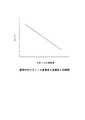
エンジンECU10は、燃料中のエタノール含有率の検出結果に基づいてエンジン100の運転に適した空燃比を決定する(図2参照)。つづいて、エンジンECU10は、決定した空燃比に基づきエンジン100の各運転状態における燃料噴射量の補正量を決定する制御を実行する。この場合、エンジンECU10は、各パラメータの相関に対応したマップを予めROMに記録しておくことで、燃料中のエタノール含有率の検出結果に基づいて燃料噴射量の補正量を迅速に決定することができる。
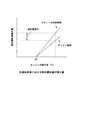
エンジンECU10は、水温センサ39からの信号を受信し、エンジン冷却水の温度が第2しきい値以上であるか否かを判断する制御を実行する。ここで、第2しきい値とは、エンジンオイルに混入した燃料、特にエタノールの顕著な気化が開始する温度を適用するが、例えば40℃とすることができる。つづいて、エンジンECU10は、エンジン冷却水の温度が第2しきい値以上であると判断した場合に、決定した燃料噴射量の補正量と、既知のガソリン100%燃料を使用する際の燃料噴射量の補正量との差分を算出する(図3参照)。
この場合、エンジンECU10は、水温センサ39の検出結果に代えて、エンジンオイルの油温を検出し、検出結果に基づいてエンジンオイルに混入した燃料の気化の開始を判断してもよい。The
In this case, the
エンジンECU10は、燃料噴射量補正量の差分の算出結果に基づいて、PCV還元ガス流量を決定する(図4参照)。つづいて、エンジンECU10は、決定したPCV還元ガス流量に基づいてPCV還元ガス流量を調節するようPCVバルブ30に指令する制御を実行する。この制御を実行することにより、クランクケースから多量に気化するエタノールによって空燃比がオーバーリッチとなる場合、PCV還元ガス流量を減少させることでオーバーリッチを解消することができる。よって、F/B制御による燃料噴射量の補正量を低減させることができる。 The
エンジンECU10は、補正量の差分に基づいて決定したPCV還元ガス流量が、PCVバルブ30が調節可能な最小の還元ガス流量より小さいか否かを判断する制御を実行する。つづいて、エンジンECU10は、決定したPCV還元ガス流量がPCVバルブ30が調節可能な最小の還元ガス流量より小さいと判断した場合に、燃料噴射系異常のMIL点灯をOBDに許可する。 The
この制御を実行することにより、燃料中のアルコール含有率から燃料噴射量の補正量を決定し、決定した補正量に基づきPCV還元ガス流量を決定し、決定したPCV還元ガス流量が調節可能な流量よりも小さいときに自己故障診断システムが燃料噴射系の異常をユーザに通知することを許可することができる。よって、アルコールとガソリンとを任意の割合で混合した燃料を使用可能な内燃機関のOBDシステムのMIL誤点灯の頻度を低減させることができる。
なお、エンジンECU10は、本発明の燃料噴射量補正量決定手段、還元ガス流量決定手段、許可手段に相当する。By executing this control, the correction amount of the fuel injection amount is determined from the alcohol content in the fuel, the PCV reducing gas flow rate is determined based on the determined correction amount, and the determined PCV reducing gas flow rate is adjustable. The self-failure diagnosis system can be allowed to notify the user of abnormality in the fuel injection system. Therefore, it is possible to reduce the frequency of MIL erroneous lighting of an OBD system of an internal combustion engine that can use a fuel in which alcohol and gasoline are mixed at an arbitrary ratio.
The
つづいて、エンジンECU10の制御の流れに沿って、車両制御システム1の動作を説明する。図5はエンジンECU10の処理の一例を示すフローチャートである。本実施例の車両制御システム1は、アルコール含有率検出手段と、燃料噴射量補正量決定手段と、還元ガス流量決定手段と、還元ガス流量調節手段と、許可手段とを備えることで、燃料中のアルコール含有率から燃料噴射量の補正量を決定し、決定した補正量に基づきPCV還元ガス流量を決定し、決定したPCV還元ガス流量が調節可能な流量よりも小さいときに、自己故障診断システムが燃料噴射系の異常をユーザに通知することを許可する制御を実行する。 Next, the operation of the vehicle control system 1 will be described along the control flow of the
エンジンECU10の制御は、エンジンの始動要求がされると、すなわちイグニッションスイッチがONにされると開始する。まず、エンジンECU10はステップS1で、アルコールセンサ41の検出結果に基づいて、燃料中のエタノール含有率を検出する。エンジンECU10は、ステップS1の処理を終えると、次のステップS2へ進む。 The control of the
ステップS2で、エンジンECU10は、ステップS1で検出した燃料中のエタノール含有率に基づいて、エンジン100の運転に適した空燃比を決定し(図2参照)、決定した空燃比に基づきエンジン100の各運転状態における燃料噴射量の補正量を決定する。エンジンECU10は、ステップS2の処理を終えると、次のステップS3へ進む。 In step S2, the
ステップS3で、エンジンECU10は、水温センサ39の検出結果に基づいて、エンジン冷却水の温度が第2しきい値以上であるか否かを判断する。ここで、第2しきい値については前述したために、その詳細な説明は省略する。エンジン冷却水の温度が第2しきい値以上でない場合(ステップS3/NO)、エンジンECU10は、エンジンオイルからのエタノール気化量、すなわち吸気通路14へ供給されるエタノール量が少量であると判断し、制御の処理を終了する。エンジン冷却水の温度が第2しきい値以上である場合(ステップS3/YES)は、エンジンECU10は次のステップS4へ進む。 In step S3, the
ステップS4で、エンジンECU10は、ステップS2で決定した燃料噴射量の補正量と、既知のガソリン100%燃料を使用する際の燃料噴射量の補正量との差分を算出し(図3参照)、算出した差分に基づきPCV還元ガス流量を決定する(図4参照)。エンジンECU10は、ステップS4の処理を終えると、次のステップS5へ進む。 In step S4, the
ステップS5で、エンジンECU10は、ステップS4で決定したPCV還元ガス流量がPCVバルブ30が調節可能な最小の還元ガス流量よりも小さいか否かを判断する。決定したPCV還元ガス流量がPCVバルブ30が調節可能な最小の還元ガス流量よりも大きい場合(ステップS5/NO)、エンジンECU10は、燃料噴射系異常のMILを点灯させる必要がないと判断し、制御の処理を終了する。決定したPCV還元ガス流量がPCVバルブ30が調節可能な最小の還元ガス流量よりも小さい場合(ステップS5/YES)は、エンジンECU10は次のステップS6へ進む。 In step S5, the
ステップS6で、エンジンECU10は、燃料噴射系異常のMIL点灯をOBDに許可する。この制御を実行することにより、内燃機関の暖機によって多量の気化エタノールが供給されることで空燃比がオーバーリッチとなる場合でも、燃料噴射系異常のMIL誤点灯を抑制することができる。よって、アルコールとガソリンとを任意の割合で混合した燃料を使用可能な内燃機関のOBDシステムのMIL誤点灯の頻度を低減させることができる。エンジンECU10は、ステップS6の処理を終えると、制御の処理を終了する。 In step S6, the
以上のように、本実施例の車両制御システム1は、アルコール含有率検出手段と、燃料噴射量補正量決定手段と、還元ガス流量決定手段と、還元ガス流量調節手段と、許可手段とによって、燃料中のアルコール含有率から燃料噴射量の補正量を決定し、決定した補正量に基づきPCV還元ガス流量を決定し、決定したPCV還元ガス流量が調節可能な流量よりも小さいときに、自己故障診断システムが燃料噴射系の異常をユーザに通知することを許可することができる。よって、アルコールとガソリンとを任意の割合で混合した燃料を使用可能な内燃機関のOBDシステムのMIL誤点灯の頻度を低減させることができる。 As described above, the vehicle control system 1 according to the present embodiment includes the alcohol content rate detection unit, the fuel injection amount correction amount determination unit, the reduction gas flow rate determination unit, the reduction gas flow rate adjustment unit, and the permission unit. When the correction amount of the fuel injection amount is determined from the alcohol content in the fuel, the PCV reducing gas flow rate is determined based on the determined correction amount, and the self-failure occurs when the determined PCV reducing gas flow rate is smaller than the adjustable flow rate. The diagnostic system can be allowed to notify the user of abnormality in the fuel injection system. Therefore, it is possible to reduce the frequency of MIL erroneous lighting of an OBD system of an internal combustion engine that can use a fuel in which alcohol and gasoline are mixed at an arbitrary ratio.
つづいて、本発明の実施例2について説明する。本実施例の車両制御システム2は、還元ガス流量調節手段がガス流量を最小に調節する時間が第1しきい値を超える場合に、ユーザに使用中の燃料を給油しないよう報知する報知手段を備える点で車両制御システム1と相違している。 Next, a second embodiment of the present invention will be described. The vehicle control system 2 of the present embodiment includes a notification unit that notifies the user not to refuel the fuel in use when the time during which the reducing gas flow rate adjustment unit adjusts the gas flow rate to the minimum exceeds the first threshold value. It differs from the vehicle control system 1 in the point provided.
本実施例の車両制御システム2は、実施例1と同様に車両内部にエンジンECU10を備えている。また、車両制御システム2は、車両内部のMIL近傍に図示しないチェックランプを備えている。このエンジンECU10およびチェックランプが、ユーザに現在使用中の燃料を給油しないよう報知する報知手段に相当する。 Similar to the first embodiment, the vehicle control system 2 of the present embodiment includes an
チェックランプは、エンジンECU10の指令に従って点灯することで、現在使用中の燃料と同一規格、すなわち、アルコール含有率がほぼ同一の燃料の給油を抑制するようユーザに報知する。この場合、チェックランプは、MIL近傍に関わらず給油の抑制をユーザに報知することができる任意の部位に設けることができる。また、チェックランプに代えて、現在使用中の燃料の給油を抑制するようユーザに報知する他の報知手段を適用することもできる。 The check lamp is lit in accordance with a command from the
エンジンECU10は、PCVバルブ30が調節するPCV還元ガス流量が、PCVバルブ30が調節可能な最小の還元ガス流量に調節されているか否かを判断する制御を実行する。この場合、エンジンECU10は、PCV還元ガス流量の決定結果(図4参照)、PCVバルブ30の開度等に基づいて、PCV還元ガス流量が最小流量に調節されているか否かを判断することができる。 The
エンジンECU10は、PCV還元ガス流量が最小流量に調節されていると判断した場合に、PCV還元ガス流量が最小流量に調節される期間の時間を計測する(図6参照)。そして、エンジンECU10は、計測した最小流量の調節時間が第1しきい値を超えるか否かを判断する。ここで、第1しきい値とは、現在使用中の燃料のアルコール含有率がMIL誤点灯を誘発するほど高いと充分に判断できる任意の最小流量の調節時間を適用することができる。 When the
エンジンECU10は、計測した最小流量の調節時間が第1しきい値を超えると判断した場合に、チェックランプを点灯させる。
この制御を実行することにより、現在使用中の燃料を継続使用することでMIL誤点灯が誘発されると判断する場合に、現在使用中の燃料と同一規格の燃料の給油を抑制するようユーザに報知することができる。よって、アルコール含有率の高い燃料の給油を抑制し、エンジンオイルからの過剰なアルコール気化を抑制することで、OBDシステムのMIL誤点灯の頻度を低減させることができる。When the
By executing this control, when it is determined that the MIL erroneous lighting is induced by continuously using the currently used fuel, the user is requested to suppress the refueling of the same standard fuel as the currently used fuel. Can be notified. Therefore, it is possible to reduce the frequency of MIL erroneous lighting of the OBD system by suppressing fuel supply with a high alcohol content rate and suppressing excessive alcohol vaporization from the engine oil.
つづいて、エンジンECU10の制御の流れに沿って、車両制御システム2の動作を説明する。図7はエンジンECU10の処理の一例を示すフローチャートである。なお、車両制御システム2のエンジンECU10は、実施例1の車両制御システム1のステップS1からステップS4の処理の後に、以下のステップS7からステップS10までの制御を行う。よってステップS1からステップS4の制御は実施例1の車両制御システム1と同一であるため、その詳細な説明は省略する。
本実施例の車両制御システム2は、PCVバルブ30が還元ガス流量を最小に調節する時間が所定時間を超える場合に、ユーザに使用中の燃料を給油しないよう報知する制御を実行する。Next, the operation of the vehicle control system 2 will be described along the control flow of the
The vehicle control system 2 of the present embodiment executes control for notifying the user not to refuel the fuel in use when the time during which the
ステップS4の処理の後に、エンジンECU10はステップS7へ進む。ステップS7で、エンジンECU10は、ステップS4の決定結果に基づき調節されたPCV還元ガス流量が最小流量であるか否かを判断する。調節されたPCV還元ガス流量が最小流量でない場合(ステップS7/NO)、エンジンECU10は、現在使用中の燃料を継続使用してもMIL誤点灯は誘発されないと判断し、制御の処理を終了する。調節されたPCV還元ガス流量が最小流量である場合(ステップS7/YES)は、エンジンECU10は次のステップS8へ進む。 After the process of step S4, the
ステップS8で、エンジンECU10は、PCV還元ガス流量が最小流量に調節される期間の時間を計測する(図6参照)。エンジンECU10は、ステップS8の処理を終えると、次のステップS9へ進む。 In step S8, the
ステップS9で、エンジンECU10は、ステップS8で計測した最小流量の調節時間が第1しきい値を超えるか否かを判断する。ここで、第1しきい値については前述したために、その詳細な説明は省略する。最小流量の調節時間が第1しきい値を超えない場合(ステップS9/NO)、エンジンECU10は、現在使用中の燃料を継続使用してもMIL誤点灯が誘発される可能性は低いと判断し、制御の処理を終了する。最小流量の調節時間が第1しきい値を超える場合(ステップS9/YES)は、エンジンECU10は次のステップS10へ進む。 In step S9, the
ステップS10で、エンジンECU10は、チェックランプを点灯させて、ユーザに現在使用中の燃料と同一規格の燃料の給油を抑制するよう報知する。この制御を実行することにより、アルコール含有率の高い燃料の給油を抑制し、エンジンオイルからの過剰なアルコール気化を抑制することで、OBDシステムのMIL誤点灯の頻度を低減させることができる。エンジンECU10は、ステップS10の処理を終えると、制御の処理を終了する。 In step S10, the
以上のように、本実施例の車両制御システム2は、還元ガス流量調節手段がガス流量を最小に調節する時間が第1しきい値を超える場合に、ユーザに使用中の燃料を給油しないよう報知することで、現在使用中の燃料を継続使用することでMIL誤点灯が誘発されると判断する場合に、現在使用中の燃料と同一規格の燃料の給油を抑制するようユーザに報知することができる。よって、アルコール含有率の高い燃料の給油を抑制し、エンジンオイルからの過剰なアルコール気化を抑制することで、OBDシステムのMIL誤点灯の頻度を低減させることができる。 As described above, the vehicle control system 2 according to the present embodiment prevents the user from refueling the fuel in use when the time during which the reducing gas flow rate adjusting unit adjusts the gas flow rate to the minimum exceeds the first threshold value. Informing the user to suppress the refueling of the fuel of the same standard as the currently used fuel when it is determined that the MIL erroneous lighting is induced by continuously using the currently used fuel. Can do. Therefore, it is possible to reduce the frequency of MIL erroneous lighting of the OBD system by suppressing fuel supply with a high alcohol content rate and suppressing excessive alcohol vaporization from the engine oil.
上記実施例は本発明を実施するための一例にすぎない。よって本発明はこれらに限定されるものではなく、特許請求の範囲に記載された本発明の要旨の範囲内において、種々の変形・変更が可能である。 The above embodiments are merely examples for carrying out the present invention. Therefore, the present invention is not limited to these, and various modifications and changes can be made within the scope of the gist of the present invention described in the claims.
1 車両制御システム
10 エンジンECU(燃料噴射量補正量決定手段,還元ガス流量決定手段,許可手段)
11 ピストン
11a 燃焼室
12 クランクシャフト
13 吸気ポート
14 吸気通路
15 排気ポート
16 排気通路
17 合流排気通路
18 吸気弁
19 排気弁
20 吸気カムシャフト
21 排気カムシャフト
22 電動VVT機構
23 油圧VVT機構
24 スロットルバルブ
25 インジェクタ
26 点火プラグ
27 イグナイタ
28 浄化触媒
29 PCV通路
30 PCVバルブ(還元ガス流量調節手段)
31 クランク角センサ
32 吸気カム角センサ
33 排気カム角センサ
34 エアフロメータ
35 スロットルポジションセンサ
36 排気温センサ
37 A/Fセンサ
38 O2センサ
39 水温センサ
40 触媒温度センサ
41 アルコールセンサ(アルコール含有率検出手段)
100 エンジン
1
DESCRIPTION OF SYMBOLS 11
31
100 engine
Claims (2)
Translated fromJapanese前記燃料中のアルコール含有率を検出するアルコール含有率検出手段と、
前記アルコール含有率検出手段の検出結果に基づいて、前記内燃機関の各運転状態における燃料噴射量の補正量を決定する燃料噴射量補正量決定手段と、
前記燃料噴射量補正量決定手段により決定された補正量に基づいて、前記還元通路を通じて吸気通路に還元させるガス流量を決定する還元ガス流量決定手段と、
前記還元ガス流量決定手段の決定結果に基づいて、前記ガス流量を調節する還元ガス流量調節手段と、
前記還元ガス流量決定手段により決定されたガス流量が、前記還元ガス流量調節手段が調節可能なガス流量より小さい場合に、前記内燃機関の自己故障診断システムが燃料噴射系の異常をユーザに通知することを許可する許可手段と、
を備えることを特徴とする内燃機関の制御装置。A control device for an internal combustion engine configured to be able to reduce blow-by gas leaked from a combustion chamber of the internal combustion engine to an intake passage through a reduction passage, and capable of using a fuel in which alcohol and gasoline are mixed at an arbitrary ratio,
Alcohol content rate detection means for detecting the alcohol content rate in the fuel;
Fuel injection amount correction amount determination means for determining a correction amount of the fuel injection amount in each operating state of the internal combustion engine based on the detection result of the alcohol content rate detection means;
Reducing gas flow rate determining means for determining a gas flow rate to be reduced to the intake passage through the reduction passage based on the correction amount determined by the fuel injection amount correction amount determining means;
Reducing gas flow rate adjusting means for adjusting the gas flow rate based on the determination result of the reducing gas flow rate determining means;
When the gas flow rate determined by the reducing gas flow rate determining means is smaller than the gas flow rate adjustable by the reducing gas flow rate adjusting means, the self-diagnosis system for the internal combustion engine notifies the user of abnormality in the fuel injection system. Permission means to allow that,
A control device for an internal combustion engine, comprising:
前記報知手段は、前記還元ガス流量調節手段がガス流量を最小に調節する時間が第1しきい値を超える場合に、ユーザに報知することを特徴とする請求項1記載の内燃機関の制御装置。
Informing means for informing the user to suppress refueling of fuel of the same standard as the fuel being used by the internal combustion engine,
2. The control device for an internal combustion engine according to claim 1, wherein the notification means notifies the user when a time during which the reducing gas flow rate adjustment means adjusts the gas flow rate to a minimum exceeds a first threshold value. .
Priority Applications (1)
| Application Number | Priority Date | Filing Date | Title |
|---|---|---|---|
| JP2009058382AJP2010209843A (en) | 2009-03-11 | 2009-03-11 | Control device for internal combustion engine |
Applications Claiming Priority (1)
| Application Number | Priority Date | Filing Date | Title |
|---|---|---|---|
| JP2009058382AJP2010209843A (en) | 2009-03-11 | 2009-03-11 | Control device for internal combustion engine |
Publications (1)
| Publication Number | Publication Date |
|---|---|
| JP2010209843Atrue JP2010209843A (en) | 2010-09-24 |
Family
ID=42970257
Family Applications (1)
| Application Number | Title | Priority Date | Filing Date |
|---|---|---|---|
| JP2009058382APendingJP2010209843A (en) | 2009-03-11 | 2009-03-11 | Control device for internal combustion engine |
Country Status (1)
| Country | Link |
|---|---|
| JP (1) | JP2010209843A (en) |
Cited By (2)
| Publication number | Priority date | Publication date | Assignee | Title |
|---|---|---|---|---|
| JP2015031213A (en)* | 2013-08-02 | 2015-02-16 | 株式会社日本自動車部品総合研究所 | Internal combustion engine |
| US10473006B2 (en) | 2014-05-21 | 2019-11-12 | Castrol Limited | Method and apparatus |
- 2009
- 2009-03-11JPJP2009058382Apatent/JP2010209843A/enactivePending
Cited By (3)
| Publication number | Priority date | Publication date | Assignee | Title |
|---|---|---|---|---|
| JP2015031213A (en)* | 2013-08-02 | 2015-02-16 | 株式会社日本自動車部品総合研究所 | Internal combustion engine |
| US9188032B2 (en) | 2013-08-02 | 2015-11-17 | Toyota Jidosha Kabushiki Kaisha | Blowby gas handling assembly for internal combustion engine |
| US10473006B2 (en) | 2014-05-21 | 2019-11-12 | Castrol Limited | Method and apparatus |
Similar Documents
| Publication | Publication Date | Title |
|---|---|---|
| JP5240059B2 (en) | Abnormality detector for exhaust gas recirculation system | |
| JP4341709B2 (en) | Control device for internal combustion engine | |
| KR100741670B1 (en) | Starter for internal combustion engine | |
| JP4477644B2 (en) | Control device for internal combustion engine | |
| US10920629B2 (en) | Oil temperature sensor diagnostic device | |
| JP2010037968A (en) | Fuel injection control device for internal combustion engine | |
| EP2888464A2 (en) | Control device and control method for internal combustion engine | |
| KR100233930B1 (en) | Control device of internal combustion engine | |
| JP2015021452A (en) | Diagnosis device of fuel level sensor | |
| JP4816466B2 (en) | Internal combustion engine control apparatus and method | |
| JP2009036023A (en) | Different fuel mixing determination device of internal combustion engine | |
| US20100300189A1 (en) | Diagnostic system for variable valve timing control system | |
| JP2009121364A (en) | Fuel injection control device | |
| JP2009191650A (en) | Control device of internal combustion engine | |
| JP2010209843A (en) | Control device for internal combustion engine | |
| JP4348705B2 (en) | Fuel injection control device for internal combustion engine | |
| JP2013130092A (en) | Method for discriminating cylinder in start for internal combustion engine | |
| JP2007192081A (en) | Control device for internal combustion engine | |
| JP2010001846A (en) | Abnormality diagnosis apparatus for internal combustion engine | |
| JP2010164007A (en) | Internal combustion engine control device | |
| JP5024880B2 (en) | Control device for internal combustion engine | |
| WO2012008487A1 (en) | Engine control device | |
| JP2010275909A (en) | Control device for internal combustion engine | |
| JP4920077B2 (en) | Control device for internal combustion engine | |
| JP2009293580A (en) | Abnormality diagnostic device of variable valve timing control system |