JP2010207574A - Attachment device and method of use - Google Patents
Attachment device and method of useDownload PDFInfo
- Publication number
- JP2010207574A JP2010207574AJP2010045912AJP2010045912AJP2010207574AJP 2010207574 AJP2010207574 AJP 2010207574AJP 2010045912 AJP2010045912 AJP 2010045912AJP 2010045912 AJP2010045912 AJP 2010045912AJP 2010207574 AJP2010207574 AJP 2010207574A
- Authority
- JP
- Japan
- Prior art keywords
- expandable
- outer shell
- section
- shows
- attachment device
- Prior art date
- Legal status (The legal status is an assumption and is not a legal conclusion. Google has not performed a legal analysis and makes no representation as to the accuracy of the status listed.)
- Pending
Links
- 238000000034methodMethods0.000titleabstractdescription79
- 239000000945fillerSubstances0.000claimsdescription33
- 210000000988bone and boneAnatomy0.000abstractdescription45
- 230000001054cortical effectEffects0.000abstractdescription5
- 238000004873anchoringMethods0.000abstractdescription2
- 238000012986modificationMethods0.000description34
- 230000004048modificationEffects0.000description34
- 206010017076FractureDiseases0.000description21
- 239000000463materialSubstances0.000description18
- 239000012530fluidSubstances0.000description14
- 238000004891communicationMethods0.000description11
- 210000001519tissueAnatomy0.000description11
- 239000003795chemical substances by applicationSubstances0.000description8
- 208000010392Bone FracturesDiseases0.000description7
- 210000002414legAnatomy0.000description7
- 230000036346tooth eruptionEffects0.000description7
- 229920000642polymerPolymers0.000description6
- 230000006835compressionEffects0.000description5
- 238000007906compressionMethods0.000description5
- 229920006149polyester-amide block copolymerPolymers0.000description5
- -1polyethylene terephthalatePolymers0.000description5
- 102000007350Bone Morphogenetic ProteinsHuman genes0.000description4
- 108010007726Bone Morphogenetic ProteinsProteins0.000description4
- 239000004593EpoxySubstances0.000description4
- 239000004743PolypropyleneSubstances0.000description4
- 229940112869bone morphogenetic proteinDrugs0.000description4
- OSGAYBCDTDRGGQ-UHFFFAOYSA-Lcalcium sulfateChemical compound[Ca+2].[O-]S([O-])(=O)=OOSGAYBCDTDRGGQ-UHFFFAOYSA-L0.000description4
- 239000004568cementSubstances0.000description4
- 229910052751metalInorganic materials0.000description4
- 239000002184metalSubstances0.000description4
- 239000004810polytetrafluoroethyleneSubstances0.000description4
- 229920001343polytetrafluoroethylenePolymers0.000description4
- 210000000614ribAnatomy0.000description4
- 210000004872soft tissueAnatomy0.000description4
- 102000008186CollagenHuman genes0.000description3
- 108010035532CollagenProteins0.000description3
- 239000000853adhesiveSubstances0.000description3
- 230000001070adhesive effectEffects0.000description3
- 229910045601alloyInorganic materials0.000description3
- 239000000956alloySubstances0.000description3
- 238000005452bendingMethods0.000description3
- 239000001506calcium phosphateSubstances0.000description3
- 229920001436collagenPolymers0.000description3
- 239000004744fabricSubstances0.000description3
- 229910001000nickel titaniumInorganic materials0.000description3
- 229920003229poly(methyl methacrylate)Polymers0.000description3
- 229920000728polyesterPolymers0.000description3
- 239000004926polymethyl methacrylateSubstances0.000description3
- 239000004814polyurethaneSubstances0.000description3
- 229920002635polyurethanePolymers0.000description3
- 239000007787solidSubstances0.000description3
- 239000000725suspensionSubstances0.000description3
- QORWJWZARLRLPR-UHFFFAOYSA-Htricalcium bis(phosphate)Chemical compound[Ca+2].[Ca+2].[Ca+2].[O-]P([O-])([O-])=O.[O-]P([O-])([O-])=OQORWJWZARLRLPR-UHFFFAOYSA-H0.000description3
- 210000000689upper legAnatomy0.000description3
- 235000014653Carica parvifloraNutrition0.000description2
- 241000243321CnidariaSpecies0.000description2
- 208000032170Congenital AbnormalitiesDiseases0.000description2
- 206010010356Congenital anomalyDiseases0.000description2
- 108010037464Cyclooxygenase 1Proteins0.000description2
- 229920004934Dacron®Polymers0.000description2
- 239000004812Fluorinated ethylene propyleneSubstances0.000description2
- HEFNNWSXXWATRW-UHFFFAOYSA-NIbuprofenChemical compoundCC(C)CC1=CC=C(C(C)C(O)=O)C=C1HEFNNWSXXWATRW-UHFFFAOYSA-N0.000description2
- 206010061246Intervertebral disc degenerationDiseases0.000description2
- 206010023509KyphosisDiseases0.000description2
- 102000002274Matrix MetalloproteinasesHuman genes0.000description2
- 108010000684Matrix MetalloproteinasesProteins0.000description2
- 102000001776Matrix metalloproteinase-9Human genes0.000description2
- 108010015302Matrix metalloproteinase-9Proteins0.000description2
- 206010028980NeoplasmDiseases0.000description2
- 239000004696Poly ether ether ketoneSubstances0.000description2
- 229920000954PolyglycolidePolymers0.000description2
- 102100038277Prostaglandin G/H synthase 1Human genes0.000description2
- 229910000831SteelInorganic materials0.000description2
- 239000004098TetracyclineSubstances0.000description2
- XLOMVQKBTHCTTD-UHFFFAOYSA-NZinc monoxideChemical compound[Zn]=OXLOMVQKBTHCTTD-UHFFFAOYSA-N0.000description2
- TZCXTZWJZNENPQ-UHFFFAOYSA-Lbarium sulfateChemical compound[Ba+2].[O-]S([O-])(=O)=OTZCXTZWJZNENPQ-UHFFFAOYSA-L0.000description2
- 239000012620biological materialSubstances0.000description2
- 230000007698birth defectEffects0.000description2
- 239000002639bone cementSubstances0.000description2
- 229910000389calcium phosphateInorganic materials0.000description2
- 235000011010calcium phosphatesNutrition0.000description2
- 230000006378damageEffects0.000description2
- 201000010099diseaseDiseases0.000description2
- 208000037265diseases, disorders, signs and symptomsDiseases0.000description2
- 239000000835fiberSubstances0.000description2
- 210000002758humerusAnatomy0.000description2
- CGIGDMFJXJATDK-UHFFFAOYSA-NindomethacinChemical compoundCC1=C(CC(O)=O)C2=CC(OC)=CC=C2N1C(=O)C1=CC=C(Cl)C=C1CGIGDMFJXJATDK-UHFFFAOYSA-N0.000description2
- 239000003112inhibitorSubstances0.000description2
- 208000014674injuryDiseases0.000description2
- 238000003780insertionMethods0.000description2
- 230000037431insertionEffects0.000description2
- 230000003834intracellular effectEffects0.000description2
- 239000011159matrix materialSubstances0.000description2
- 150000002739metalsChemical class0.000description2
- 239000000041non-steroidal anti-inflammatory agentSubstances0.000description2
- 229940021182non-steroidal anti-inflammatory drugDrugs0.000description2
- 229920001778nylonPolymers0.000description2
- 230000002188osteogenic effectEffects0.000description2
- 230000035515penetrationEffects0.000description2
- 229920009441perflouroethylene propylenePolymers0.000description2
- 229920001432poly(L-lactide)Polymers0.000description2
- 229920001652poly(etherketoneketone)Polymers0.000description2
- 229920001610polycaprolactonePolymers0.000description2
- 239000004632polycaprolactoneSubstances0.000description2
- 229920002530polyetherether ketonePolymers0.000description2
- 229920000139polyethylene terephthalatePolymers0.000description2
- 239000005020polyethylene terephthalateSubstances0.000description2
- 239000004633polyglycolic acidSubstances0.000description2
- 229920001155polypropylenePolymers0.000description2
- 229920001296polysiloxanePolymers0.000description2
- 239000012857radioactive materialSubstances0.000description2
- 210000001991scapulaAnatomy0.000description2
- 206010039722scoliosisDiseases0.000description2
- QFJCIRLUMZQUOT-HPLJOQBZSA-NsirolimusChemical compoundC1C[C@@H](O)[C@H](OC)C[C@@H]1C[C@@H](C)[C@H]1OC(=O)[C@@H]2CCCCN2C(=O)C(=O)[C@](O)(O2)[C@H](C)CC[C@H]2C[C@H](OC)/C(C)=C/C=C/C=C/[C@@H](C)C[C@@H](C)C(=O)[C@H](OC)[C@H](O)/C(C)=C/[C@@H](C)C(=O)C1QFJCIRLUMZQUOT-HPLJOQBZSA-N0.000description2
- 241000894007speciesSpecies0.000description2
- 238000001228spectrumMethods0.000description2
- 239000010959steelSubstances0.000description2
- 238000001356surgical procedureMethods0.000description2
- 229930101283tetracyclineNatural products0.000description2
- 229960002180tetracyclineDrugs0.000description2
- 235000019364tetracyclineNutrition0.000description2
- 150000003522tetracyclinesChemical class0.000description2
- 210000002303tibiaAnatomy0.000description2
- 239000010936titaniumSubstances0.000description2
- 230000008733traumaEffects0.000description2
- 230000000472traumatic effectEffects0.000description2
- 229920000785ultra high molecular weight polyethylenePolymers0.000description2
- KIUKXJAPPMFGSW-DNGZLQJQSA-N(2S,3S,4S,5R,6R)-6-[(2S,3R,4R,5S,6R)-3-Acetamido-2-[(2S,3S,4R,5R,6R)-6-[(2R,3R,4R,5S,6R)-3-acetamido-2,5-dihydroxy-6-(hydroxymethyl)oxan-4-yl]oxy-2-carboxy-4,5-dihydroxyoxan-3-yl]oxy-5-hydroxy-6-(hydroxymethyl)oxan-4-yl]oxy-3,4,5-trihydroxyoxane-2-carboxylic acidChemical compoundCC(=O)N[C@H]1[C@H](O)O[C@H](CO)[C@@H](O)[C@@H]1O[C@H]1[C@H](O)[C@@H](O)[C@H](O[C@H]2[C@@H]([C@@H](O[C@H]3[C@@H]([C@@H](O)[C@H](O)[C@H](O3)C(O)=O)O)[C@H](O)[C@@H](CO)O2)NC(C)=O)[C@@H](C(O)=O)O1KIUKXJAPPMFGSW-DNGZLQJQSA-N0.000description1
- DSUFPYCILZXJFF-UHFFFAOYSA-N4-[[4-[[4-(pentoxycarbonylamino)cyclohexyl]methyl]cyclohexyl]carbamoyloxy]butyl n-[4-[[4-(butoxycarbonylamino)cyclohexyl]methyl]cyclohexyl]carbamateChemical compoundC1CC(NC(=O)OCCCCC)CCC1CC1CCC(NC(=O)OCCCCOC(=O)NC2CCC(CC3CCC(CC3)NC(=O)OCCCC)CC2)CC1DSUFPYCILZXJFF-UHFFFAOYSA-N0.000description1
- BSYNRYMUTXBXSQ-FOQJRBATSA-N59096-14-9Chemical compoundCC(=O)OC1=CC=CC=C1[14C](O)=OBSYNRYMUTXBXSQ-FOQJRBATSA-N0.000description1
- BSYNRYMUTXBXSQ-UHFFFAOYSA-NAspirinChemical compoundCC(=O)OC1=CC=CC=C1C(O)=OBSYNRYMUTXBXSQ-UHFFFAOYSA-N0.000description1
- 229910000531Co alloyInorganic materials0.000description1
- 206010010214Compression fractureDiseases0.000description1
- 108010037462Cyclooxygenase 2Proteins0.000description1
- 229920000219Ethylene vinyl alcoholPolymers0.000description1
- 206010018720Greenstick fractureDiseases0.000description1
- 206010021143HypoxiaDiseases0.000description1
- JVTAAEKCZFNVCJ-REOHCLBHSA-NL-lactic acidChemical compoundC[C@H](O)C(O)=OJVTAAEKCZFNVCJ-REOHCLBHSA-N0.000description1
- 102000010445LactoferrinHuman genes0.000description1
- 108010063045LactoferrinProteins0.000description1
- 229920000106Liquid crystal polymerPolymers0.000description1
- 239000004977Liquid-crystal polymers (LCPs)Substances0.000description1
- 229910001182Mo alloyInorganic materials0.000description1
- ZOKXTWBITQBERF-UHFFFAOYSA-NMolybdenumChemical compound[Mo]ZOKXTWBITQBERF-UHFFFAOYSA-N0.000description1
- 239000004677NylonSubstances0.000description1
- 208000002565Open FracturesDiseases0.000description1
- OAICVXFJPJFONN-UHFFFAOYSA-NPhosphorusChemical compound[P]OAICVXFJPJFONN-UHFFFAOYSA-N0.000description1
- 229920008285Poly(ether ketone) PEKPolymers0.000description1
- 229920002614Polyether block amidePolymers0.000description1
- 239000004721Polyphenylene oxideSubstances0.000description1
- 102100038280Prostaglandin G/H synthase 2Human genes0.000description1
- 229910000691Re alloyInorganic materials0.000description1
- 206010041591Spinal osteoarthritisDiseases0.000description1
- 208000007103SpondylolisthesisDiseases0.000description1
- 208000010040Sprains and StrainsDiseases0.000description1
- 208000007536ThrombosisDiseases0.000description1
- RTAQQCXQSZGOHL-UHFFFAOYSA-NTitaniumChemical compound[Ti]RTAQQCXQSZGOHL-UHFFFAOYSA-N0.000description1
- 239000004699Ultra-high molecular weight polyethyleneSubstances0.000description1
- 229920000508VectranPolymers0.000description1
- 239000004979VectranSubstances0.000description1
- HCHKCACWOHOZIP-UHFFFAOYSA-NZincChemical compound[Zn]HCHKCACWOHOZIP-UHFFFAOYSA-N0.000description1
- QXZUUHYBWMWJHK-UHFFFAOYSA-N[Co].[Ni]Chemical compound[Co].[Ni]QXZUUHYBWMWJHK-UHFFFAOYSA-N0.000description1
- HZEWFHLRYVTOIW-UHFFFAOYSA-N[Ti].[Ni]Chemical compound[Ti].[Ni]HZEWFHLRYVTOIW-UHFFFAOYSA-N0.000description1
- 239000006096absorbing agentSubstances0.000description1
- 229960001138acetylsalicylic acidDrugs0.000description1
- 239000002253acidSubstances0.000description1
- 150000007513acidsChemical class0.000description1
- 229940013181advilDrugs0.000description1
- 125000001931aliphatic groupChemical group0.000description1
- 239000002260anti-inflammatory agentSubstances0.000description1
- 229940121363anti-inflammatory agentDrugs0.000description1
- 125000003118aryl groupChemical group0.000description1
- 230000000712assemblyEffects0.000description1
- 238000000429assemblyMethods0.000description1
- 239000011324beadSubstances0.000description1
- 239000005313bioactive glassSubstances0.000description1
- 230000015572biosynthetic processEffects0.000description1
- WMWLMWRWZQELOS-UHFFFAOYSA-Nbismuth(III) oxideInorganic materialsO=[Bi]O[Bi]=OWMWLMWRWZQELOS-UHFFFAOYSA-N0.000description1
- 210000002805bone matrixAnatomy0.000description1
- 229940047495celebrexDrugs0.000description1
- RZEKVGVHFLEQIL-UHFFFAOYSA-NcelecoxibChemical compoundC1=CC(C)=CC=C1C1=CC(C(F)(F)F)=NN1C1=CC=C(S(N)(=O)=O)C=C1RZEKVGVHFLEQIL-UHFFFAOYSA-N0.000description1
- 229920002301cellulose acetatePolymers0.000description1
- 239000000919ceramicSubstances0.000description1
- 239000000788chromium alloySubstances0.000description1
- 210000003109clavicleAnatomy0.000description1
- 229920006018co-polyamidePolymers0.000description1
- 229940111134coxibsDrugs0.000description1
- 238000002788crimpingMethods0.000description1
- 239000003260cyclooxygenase 1 inhibitorSubstances0.000description1
- 239000003255cyclooxygenase 2 inhibitorSubstances0.000description1
- 230000002559cytogenic effectEffects0.000description1
- 229940127089cytotoxic agentDrugs0.000description1
- 239000002254cytotoxic agentSubstances0.000description1
- 231100000599cytotoxic agentToxicity0.000description1
- 230000007850degenerationEffects0.000description1
- 238000004925denaturationMethods0.000description1
- 230000036425denaturationEffects0.000description1
- 238000011161developmentMethods0.000description1
- 230000018109developmental processEffects0.000description1
- 229940039227diagnostic agentDrugs0.000description1
- 239000000032diagnostic agentSubstances0.000description1
- 238000010586diagramMethods0.000description1
- XEYBRNLFEZDVAW-ARSRFYASSA-NdinoprostoneChemical compoundCCCCC[C@H](O)\C=C\[C@H]1[C@H](O)CC(=O)[C@@H]1C\C=C/CCCC(O)=OXEYBRNLFEZDVAW-ARSRFYASSA-N0.000description1
- 229960002986dinoprostoneDrugs0.000description1
- 239000003814drugSubstances0.000description1
- 238000012377drug deliveryMethods0.000description1
- 230000000694effectsEffects0.000description1
- 229910000701elgiloys (Co-Cr-Ni Alloy)Inorganic materials0.000description1
- 210000003038endotheliumAnatomy0.000description1
- 238000005516engineering processMethods0.000description1
- 125000003700epoxy groupChemical group0.000description1
- HQQADJVZYDDRJT-UHFFFAOYSA-Nethene;prop-1-eneChemical groupC=C.CC=CHQQADJVZYDDRJT-UHFFFAOYSA-N0.000description1
- 239000004715ethylene vinyl alcoholSubstances0.000description1
- 238000004299exfoliationMethods0.000description1
- 230000009969flowable effectEffects0.000description1
- 210000002683footAnatomy0.000description1
- 210000000610foot boneAnatomy0.000description1
- PCHJSUWPFVWCPO-UHFFFAOYSA-NgoldChemical compound[Au]PCHJSUWPFVWCPO-UHFFFAOYSA-N0.000description1
- 229910052737goldInorganic materials0.000description1
- 239000010931goldSubstances0.000description1
- 239000003102growth factorSubstances0.000description1
- 210000004349growth plateAnatomy0.000description1
- RZXDTJIXPSCHCI-UHFFFAOYSA-Nhexa-1,5-diene-2,5-diolChemical compoundOC(=C)CCC(O)=CRZXDTJIXPSCHCI-UHFFFAOYSA-N0.000description1
- 229920002674hyaluronanPolymers0.000description1
- 229960003160hyaluronic acidDrugs0.000description1
- 229910052588hydroxylapatiteInorganic materials0.000description1
- 230000001146hypoxic effectEffects0.000description1
- 229960001680ibuprofenDrugs0.000description1
- 229940125721immunosuppressive agentDrugs0.000description1
- 239000003018immunosuppressive agentSubstances0.000description1
- 239000007943implantSubstances0.000description1
- 238000002513implantationMethods0.000description1
- 229960000905indomethacinDrugs0.000description1
- 230000028709inflammatory responseEffects0.000description1
- 230000005764inhibitory processEffects0.000description1
- 238000011835investigationMethods0.000description1
- 150000002576ketonesChemical class0.000description1
- CSSYQJWUGATIHM-IKGCZBKSSA-Nl-phenylalanyl-l-lysyl-l-cysteinyl-l-arginyl-l-arginyl-l-tryptophyl-l-glutaminyl-l-tryptophyl-l-arginyl-l-methionyl-l-lysyl-l-lysyl-l-leucylglycyl-l-alanyl-l-prolyl-l-seryl-l-isoleucyl-l-threonyl-l-cysteinyl-l-valyl-l-arginyl-l-arginyl-l-alanyl-l-phenylalChemical compoundC([C@H](N)C(=O)N[C@@H](CCCCN)C(=O)N[C@@H](CS)C(=O)N[C@@H](CCCNC(N)=N)C(=O)N[C@@H](CCCNC(N)=N)C(=O)N[C@@H](CC=1C2=CC=CC=C2NC=1)C(=O)N[C@@H](CCC(N)=O)C(=O)N[C@@H](CC=1C2=CC=CC=C2NC=1)C(=O)N[C@@H](CCCNC(N)=N)C(=O)N[C@@H](CCSC)C(=O)N[C@@H](CCCCN)C(=O)N[C@@H](CCCCN)C(=O)N[C@@H](CC(C)C)C(=O)NCC(=O)N[C@@H](C)C(=O)N1CCC[C@H]1C(=O)N[C@@H](CO)C(=O)N[C@@H]([C@@H](C)CC)C(=O)N[C@@H]([C@@H](C)O)C(=O)N[C@@H](CS)C(=O)N[C@@H](C(C)C)C(=O)N[C@@H](CCCNC(N)=N)C(=O)N[C@@H](CCCNC(N)=N)C(=O)N[C@@H](C)C(=O)N[C@@H](CC=1C=CC=CC=1)C(O)=O)C1=CC=CC=C1CSSYQJWUGATIHM-IKGCZBKSSA-N0.000description1
- 229940078795lactoferrinDrugs0.000description1
- 235000021242lactoferrinNutrition0.000description1
- 230000001050lubricating effectEffects0.000description1
- HYYBABOKPJLUIN-UHFFFAOYSA-Nmefenamic acidChemical compoundCC1=CC=CC(NC=2C(=CC=CC=2)C(O)=O)=C1CHYYBABOKPJLUIN-UHFFFAOYSA-N0.000description1
- 229960003464mefenamic acidDrugs0.000description1
- 229910052750molybdenumInorganic materials0.000description1
- 239000011733molybdenumSubstances0.000description1
- HLXZNVUGXRDIFK-UHFFFAOYSA-Nnickel titaniumChemical compound[Ti].[Ti].[Ti].[Ti].[Ti].[Ti].[Ti].[Ti].[Ti].[Ti].[Ti].[Ni].[Ni].[Ni].[Ni].[Ni].[Ni].[Ni].[Ni].[Ni].[Ni].[Ni].[Ni].[Ni].[Ni]HLXZNVUGXRDIFK-UHFFFAOYSA-N0.000description1
- 230000002138osteoinductive effectEffects0.000description1
- 239000002245particleSubstances0.000description1
- 210000004417patellaAnatomy0.000description1
- 230000037361pathwayEffects0.000description1
- 210000004197pelvisAnatomy0.000description1
- XYJRXVWERLGGKC-UHFFFAOYSA-Dpentacalcium;hydroxide;triphosphateChemical compound[OH-].[Ca+2].[Ca+2].[Ca+2].[Ca+2].[Ca+2].[O-]P([O-])([O-])=O.[O-]P([O-])([O-])=O.[O-]P([O-])([O-])=OXYJRXVWERLGGKC-UHFFFAOYSA-D0.000description1
- 229920003023plasticPolymers0.000description1
- 239000004033plasticSubstances0.000description1
- 229920002463poly(p-dioxanone) polymerPolymers0.000description1
- 229920006260polyaryletherketonePolymers0.000description1
- 239000000622polydioxanoneSubstances0.000description1
- 229920000647polyepoxidePolymers0.000description1
- 229920000570polyetherPolymers0.000description1
- 229920000120polyethyl acrylatePolymers0.000description1
- 239000004626polylactic acidSubstances0.000description1
- 239000004800polyvinyl chlorideSubstances0.000description1
- 239000000843powderSubstances0.000description1
- XEYBRNLFEZDVAW-UHFFFAOYSA-Nprostaglandin E2Natural productsCCCCCC(O)C=CC1C(O)CC(=O)C1CC=CCCCC(O)=OXEYBRNLFEZDVAW-UHFFFAOYSA-N0.000description1
- 108090000623proteins and genesProteins0.000description1
- 230000017854proteolysisEffects0.000description1
- 229940099538rapamuneDrugs0.000description1
- ZAHRKKWIAAJSAO-UHFFFAOYSA-NrapamycinNatural productsCOCC(O)C(=C/C(C)C(=O)CC(OC(=O)C1CCCCN1C(=O)C(=O)C2(O)OC(CC(OC)C(=CC=CC=CC(C)CC(C)C(=O)C)C)CCC2C)C(C)CC3CCC(O)C(C3)OC)CZAHRKKWIAAJSAO-UHFFFAOYSA-N0.000description1
- RZJQGNCSTQAWON-UHFFFAOYSA-NrofecoxibChemical compoundC1=CC(S(=O)(=O)C)=CC=C1C1=C(C=2C=CC=CC=2)C(=O)OC1RZJQGNCSTQAWON-UHFFFAOYSA-N0.000description1
- 238000000926separation methodMethods0.000description1
- 230000035939shockEffects0.000description1
- 229960002930sirolimusDrugs0.000description1
- 208000005801spondylosisDiseases0.000description1
- 230000006641stabilisationEffects0.000description1
- 238000011105stabilizationMethods0.000description1
- 229910001220stainless steelInorganic materials0.000description1
- 239000010935stainless steelSubstances0.000description1
- 229910001256stainless steel alloyInorganic materials0.000description1
- 230000003068static effectEffects0.000description1
- 210000001562sternumAnatomy0.000description1
- 238000003786synthesis reactionMethods0.000description1
- 229910052715tantalumInorganic materials0.000description1
- GUVRBAGPIYLISA-UHFFFAOYSA-Ntantalum atomChemical compound[Ta]GUVRBAGPIYLISA-UHFFFAOYSA-N0.000description1
- 210000001137tarsal boneAnatomy0.000description1
- 229940124597therapeutic agentDrugs0.000description1
- 230000001225therapeutic effectEffects0.000description1
- 229920001169thermoplasticPolymers0.000description1
- 239000004416thermosoftening plasticSubstances0.000description1
- 229910052719titaniumInorganic materials0.000description1
- 210000003371toeAnatomy0.000description1
- 229910000391tricalcium phosphateInorganic materials0.000description1
- 235000019731tricalcium phosphateNutrition0.000description1
- 229940078499tricalcium phosphateDrugs0.000description1
- 229940087652vioxxDrugs0.000description1
- 230000003313weakening effectEffects0.000description1
- 238000003466weldingMethods0.000description1
- 229910052725zincInorganic materials0.000description1
- 239000011701zincSubstances0.000description1
- 239000011787zinc oxideSubstances0.000description1
Images


Classifications
- A—HUMAN NECESSITIES
- A61—MEDICAL OR VETERINARY SCIENCE; HYGIENE
- A61B—DIAGNOSIS; SURGERY; IDENTIFICATION
- A61B17/00—Surgical instruments, devices or methods
- A61B17/56—Surgical instruments or methods for treatment of bones or joints; Devices specially adapted therefor
- A61B17/58—Surgical instruments or methods for treatment of bones or joints; Devices specially adapted therefor for osteosynthesis, e.g. bone plates, screws or setting implements
- A61B17/68—Internal fixation devices, including fasteners and spinal fixators, even if a part thereof projects from the skin
- A61B17/84—Fasteners therefor or fasteners being internal fixation devices
- A61B17/86—Pins or screws or threaded wires; nuts therefor
- A61B17/8625—Shanks, i.e. parts contacting bone tissue
- A—HUMAN NECESSITIES
- A61—MEDICAL OR VETERINARY SCIENCE; HYGIENE
- A61B—DIAGNOSIS; SURGERY; IDENTIFICATION
- A61B17/00—Surgical instruments, devices or methods
- A61B17/56—Surgical instruments or methods for treatment of bones or joints; Devices specially adapted therefor
- A61B17/58—Surgical instruments or methods for treatment of bones or joints; Devices specially adapted therefor for osteosynthesis, e.g. bone plates, screws or setting implements
- A61B17/68—Internal fixation devices, including fasteners and spinal fixators, even if a part thereof projects from the skin
- A61B17/686—Plugs, i.e. elements forming interface between bone hole and implant or fastener, e.g. screw
- A—HUMAN NECESSITIES
- A61—MEDICAL OR VETERINARY SCIENCE; HYGIENE
- A61B—DIAGNOSIS; SURGERY; IDENTIFICATION
- A61B17/00—Surgical instruments, devices or methods
- A61B17/56—Surgical instruments or methods for treatment of bones or joints; Devices specially adapted therefor
- A61B17/58—Surgical instruments or methods for treatment of bones or joints; Devices specially adapted therefor for osteosynthesis, e.g. bone plates, screws or setting implements
- A61B17/68—Internal fixation devices, including fasteners and spinal fixators, even if a part thereof projects from the skin
- A61B17/70—Spinal positioners or stabilisers, e.g. stabilisers comprising fluid filler in an implant
- A—HUMAN NECESSITIES
- A61—MEDICAL OR VETERINARY SCIENCE; HYGIENE
- A61B—DIAGNOSIS; SURGERY; IDENTIFICATION
- A61B17/00—Surgical instruments, devices or methods
- A61B17/56—Surgical instruments or methods for treatment of bones or joints; Devices specially adapted therefor
- A61B17/58—Surgical instruments or methods for treatment of bones or joints; Devices specially adapted therefor for osteosynthesis, e.g. bone plates, screws or setting implements
- A61B17/68—Internal fixation devices, including fasteners and spinal fixators, even if a part thereof projects from the skin
- A61B17/72—Intramedullary devices, e.g. pins or nails
- A61B17/7233—Intramedullary devices, e.g. pins or nails with special means of locking the nail to the bone
- A61B17/7258—Intramedullary devices, e.g. pins or nails with special means of locking the nail to the bone with laterally expanding parts, e.g. for gripping the bone
- A—HUMAN NECESSITIES
- A61—MEDICAL OR VETERINARY SCIENCE; HYGIENE
- A61B—DIAGNOSIS; SURGERY; IDENTIFICATION
- A61B17/00—Surgical instruments, devices or methods
- A61B17/56—Surgical instruments or methods for treatment of bones or joints; Devices specially adapted therefor
- A61B17/58—Surgical instruments or methods for treatment of bones or joints; Devices specially adapted therefor for osteosynthesis, e.g. bone plates, screws or setting implements
- A61B17/68—Internal fixation devices, including fasteners and spinal fixators, even if a part thereof projects from the skin
- A61B17/74—Devices for the head or neck or trochanter of the femur
- A61B17/742—Devices for the head or neck or trochanter of the femur having one or more longitudinal elements oriented along or parallel to the axis of the neck
- A61B17/744—Devices for the head or neck or trochanter of the femur having one or more longitudinal elements oriented along or parallel to the axis of the neck the longitudinal elements coupled to an intramedullary nail
- A—HUMAN NECESSITIES
- A61—MEDICAL OR VETERINARY SCIENCE; HYGIENE
- A61B—DIAGNOSIS; SURGERY; IDENTIFICATION
- A61B17/00—Surgical instruments, devices or methods
- A61B17/56—Surgical instruments or methods for treatment of bones or joints; Devices specially adapted therefor
- A61B17/58—Surgical instruments or methods for treatment of bones or joints; Devices specially adapted therefor for osteosynthesis, e.g. bone plates, screws or setting implements
- A61B17/68—Internal fixation devices, including fasteners and spinal fixators, even if a part thereof projects from the skin
- A61B17/84—Fasteners therefor or fasteners being internal fixation devices
- A61B17/86—Pins or screws or threaded wires; nuts therefor
- A61B17/8685—Pins or screws or threaded wires; nuts therefor comprising multiple separate parts
- A—HUMAN NECESSITIES
- A61—MEDICAL OR VETERINARY SCIENCE; HYGIENE
- A61C—DENTISTRY; APPARATUS OR METHODS FOR ORAL OR DENTAL HYGIENE
- A61C8/00—Means to be fixed to the jaw-bone for consolidating natural teeth or for fixing dental prostheses thereon; Dental implants; Implanting tools
- A61C8/0018—Means to be fixed to the jaw-bone for consolidating natural teeth or for fixing dental prostheses thereon; Dental implants; Implanting tools characterised by the shape
- A61C8/0033—Expandable implants; Implants with extendable elements
- A—HUMAN NECESSITIES
- A61—MEDICAL OR VETERINARY SCIENCE; HYGIENE
- A61B—DIAGNOSIS; SURGERY; IDENTIFICATION
- A61B17/00—Surgical instruments, devices or methods
- A61B2017/00681—Aspects not otherwise provided for
- A61B2017/00725—Calibration or performance testing
- A—HUMAN NECESSITIES
- A61—MEDICAL OR VETERINARY SCIENCE; HYGIENE
- A61B—DIAGNOSIS; SURGERY; IDENTIFICATION
- A61B17/00—Surgical instruments, devices or methods
- A61B17/04—Surgical instruments, devices or methods for suturing wounds; Holders or packages for needles or suture materials
- A61B17/0401—Suture anchors, buttons or pledgets, i.e. means for attaching sutures to bone, cartilage or soft tissue; Instruments for applying or removing suture anchors
- A61B2017/042—Suture anchors, buttons or pledgets, i.e. means for attaching sutures to bone, cartilage or soft tissue; Instruments for applying or removing suture anchors plastically deformed during insertion
- A61B2017/0422—Suture anchors, buttons or pledgets, i.e. means for attaching sutures to bone, cartilage or soft tissue; Instruments for applying or removing suture anchors plastically deformed during insertion by insertion of a separate member into the body of the anchor
- A61B2017/0424—Suture anchors, buttons or pledgets, i.e. means for attaching sutures to bone, cartilage or soft tissue; Instruments for applying or removing suture anchors plastically deformed during insertion by insertion of a separate member into the body of the anchor the separate member staying in the anchor after placement
- A—HUMAN NECESSITIES
- A61—MEDICAL OR VETERINARY SCIENCE; HYGIENE
- A61B—DIAGNOSIS; SURGERY; IDENTIFICATION
- A61B17/00—Surgical instruments, devices or methods
- A61B17/04—Surgical instruments, devices or methods for suturing wounds; Holders or packages for needles or suture materials
- A61B17/0401—Suture anchors, buttons or pledgets, i.e. means for attaching sutures to bone, cartilage or soft tissue; Instruments for applying or removing suture anchors
- A61B2017/042—Suture anchors, buttons or pledgets, i.e. means for attaching sutures to bone, cartilage or soft tissue; Instruments for applying or removing suture anchors plastically deformed during insertion
- A61B2017/0422—Suture anchors, buttons or pledgets, i.e. means for attaching sutures to bone, cartilage or soft tissue; Instruments for applying or removing suture anchors plastically deformed during insertion by insertion of a separate member into the body of the anchor
- A61B2017/0425—Suture anchors, buttons or pledgets, i.e. means for attaching sutures to bone, cartilage or soft tissue; Instruments for applying or removing suture anchors plastically deformed during insertion by insertion of a separate member into the body of the anchor the anchor or the separate member comprising threads, e.g. a set screw in the anchor
- A—HUMAN NECESSITIES
- A61—MEDICAL OR VETERINARY SCIENCE; HYGIENE
- A61B—DIAGNOSIS; SURGERY; IDENTIFICATION
- A61B17/00—Surgical instruments, devices or methods
- A61B17/04—Surgical instruments, devices or methods for suturing wounds; Holders or packages for needles or suture materials
- A61B17/0401—Suture anchors, buttons or pledgets, i.e. means for attaching sutures to bone, cartilage or soft tissue; Instruments for applying or removing suture anchors
- A61B2017/0427—Suture anchors, buttons or pledgets, i.e. means for attaching sutures to bone, cartilage or soft tissue; Instruments for applying or removing suture anchors having anchoring barbs or pins extending outwardly from the anchor body
- A61B2017/0429—Suture anchors, buttons or pledgets, i.e. means for attaching sutures to bone, cartilage or soft tissue; Instruments for applying or removing suture anchors having anchoring barbs or pins extending outwardly from the anchor body the barbs being expanded by a mechanical mechanism which also locks them in the expanded state
- A61B2017/043—Suture anchors, buttons or pledgets, i.e. means for attaching sutures to bone, cartilage or soft tissue; Instruments for applying or removing suture anchors having anchoring barbs or pins extending outwardly from the anchor body the barbs being expanded by a mechanical mechanism which also locks them in the expanded state by insertion of a separate spreading member into the anchor
- A61B2017/0432—Suture anchors, buttons or pledgets, i.e. means for attaching sutures to bone, cartilage or soft tissue; Instruments for applying or removing suture anchors having anchoring barbs or pins extending outwardly from the anchor body the barbs being expanded by a mechanical mechanism which also locks them in the expanded state by insertion of a separate spreading member into the anchor the separate member staying in the anchor after placement
- A—HUMAN NECESSITIES
- A61—MEDICAL OR VETERINARY SCIENCE; HYGIENE
- A61B—DIAGNOSIS; SURGERY; IDENTIFICATION
- A61B17/00—Surgical instruments, devices or methods
- A61B17/04—Surgical instruments, devices or methods for suturing wounds; Holders or packages for needles or suture materials
- A61B17/0401—Suture anchors, buttons or pledgets, i.e. means for attaching sutures to bone, cartilage or soft tissue; Instruments for applying or removing suture anchors
- A61B2017/0427—Suture anchors, buttons or pledgets, i.e. means for attaching sutures to bone, cartilage or soft tissue; Instruments for applying or removing suture anchors having anchoring barbs or pins extending outwardly from the anchor body
- A61B2017/0429—Suture anchors, buttons or pledgets, i.e. means for attaching sutures to bone, cartilage or soft tissue; Instruments for applying or removing suture anchors having anchoring barbs or pins extending outwardly from the anchor body the barbs being expanded by a mechanical mechanism which also locks them in the expanded state
- A61B2017/043—Suture anchors, buttons or pledgets, i.e. means for attaching sutures to bone, cartilage or soft tissue; Instruments for applying or removing suture anchors having anchoring barbs or pins extending outwardly from the anchor body the barbs being expanded by a mechanical mechanism which also locks them in the expanded state by insertion of a separate spreading member into the anchor
- A61B2017/0433—Suture anchors, buttons or pledgets, i.e. means for attaching sutures to bone, cartilage or soft tissue; Instruments for applying or removing suture anchors having anchoring barbs or pins extending outwardly from the anchor body the barbs being expanded by a mechanical mechanism which also locks them in the expanded state by insertion of a separate spreading member into the anchor the anchor or the separate member comprising threads, e.g. a set screw or a worm gear for moving spreading members
Landscapes
- Health & Medical Sciences (AREA)
- Orthopedic Medicine & Surgery (AREA)
- Life Sciences & Earth Sciences (AREA)
- Surgery (AREA)
- Neurology (AREA)
- Veterinary Medicine (AREA)
- Public Health (AREA)
- General Health & Medical Sciences (AREA)
- Animal Behavior & Ethology (AREA)
- Molecular Biology (AREA)
- Medical Informatics (AREA)
- Heart & Thoracic Surgery (AREA)
- Biomedical Technology (AREA)
- Engineering & Computer Science (AREA)
- Nuclear Medicine, Radiotherapy & Molecular Imaging (AREA)
- Oral & Maxillofacial Surgery (AREA)
- Dentistry (AREA)
- Epidemiology (AREA)
- Surgical Instruments (AREA)
- Prostheses (AREA)
Abstract
Description
Translated fromJapanese (関連出願への相互参照)
本出願は、2009年3月9日に出願された米国出願第12/400,735号に基づく優先権を主張しており、この米国出願は、その全体が本明細書中に参考として援用される。(Cross-reference to related applications)
This application claims priority from US application Ser. No. 12 / 400,735, filed Mar. 9, 2009, which is hereby incorporated by reference in its entirety. The
(1.発明の分野)
本発明は、一般に、骨への取り付けのためのデバイスおよび方法に関する。(1. Field of the Invention)
The present invention relates generally to devices and methods for attachment to bone.
(2.関連技術の説明)
脊椎中の1つ以上の椎骨の圧迫骨折のような骨折した骨は、内部固定で処置され得る。脊椎安定化に必要とされる任意の適応症もまた、内部固定化によって処置され得る。例は、脊柱側弯症、脊柱後弯症、脊椎辷り症(spondylothisthesis)および回転、分節不安定性、例えば、疾患および外傷および先天的欠損症によって引き起こされる円板変性および骨折、および腫瘍によって引き起こされる変性を含む。(2. Explanation of related technology)
A fractured bone, such as a compression fracture of one or more vertebrae in the spine, can be treated with internal fixation. Any indication required for spinal stabilization can also be treated by internal fixation. Examples include scoliosis, kyphosis, spondylosis and rotation, segmental instability, such as disc degeneration and fractures caused by disease and trauma and birth defects, and degeneration caused by tumors Including.
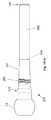
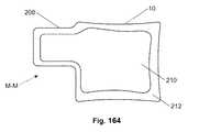
図1に示されるように、脊椎中の内部固定化は、しばしば、最初、固定ねじを椎骨10の椎弓根および椎体中にねじ込むことによって達成される。図2は、固定化ねじが次いで、代表的には、1つ以上の弱体化した椎骨10間の支持を提供する剛性の固定化ロッドまたはプレートに取り付けられることを示す。この支持は、しばしば、固定化ねじが挿入された椎骨10を固定化する。 As shown in FIG. 1, internal fixation in the spine is often accomplished by first screwing a fixation screw into the pedicle and vertebral body of the
図3は、しばしば、多数の固定化ねじ12が貫通して配備される(deployed)固定化ロッド14またはプレート220を有する現存する固定化システムを示す。ねじヘッド18は、固定化ロッド14が固定化ねじ12から分離することを防ぐ。固定化ねじ12はまた、しばしば固定化ロッド14に対して静止したねじ長手方向軸20を有するねじ本体16を有する。 FIG. 3 often shows an existing fixation system having a
図4は、いくつかの現存する固定化システムでは、固定化ねじ12が、矢印で示されるように、ねじの長手方向軸20が固定化ロッド14に対して回転し得るような様式で固定化ロッド14またはプレート220に取り付けられた多軸ねじであり得ることを示す。 FIG. 4 shows that in some existing fixation systems, the
固定化ねじ12を後退すること、または緩めることは、完全な破壊までの固定化の弱化を引き起こし得、またはさらなる合併症さえ生じる。 Retracting or loosening the
さらに、骨はしばしば弱く、そして重負荷の下では、骨は弱り得、そして固定化ねじ12は、骨から剥ぎ取られ得、完全な破壊および骨へのさらなる損傷を生じる。 Further, the bone is often weak and under heavy loads, the bone can weaken and the
従って、後退のリスクを実質的になくし得、そしてより高い係留力を提供し得る固定化ねじが所望される。骨破壊をまた最小にし得る固定化ねじが所望される。 Accordingly, a fixation screw that can substantially eliminate the risk of retraction and that can provide higher anchoring forces is desired. A fixation screw that can also minimize bone fracture is desired.
(発明の要旨)
拡大可能な取り付けデバイスおよびこのデバイスを用いる方法が開示される。この拡大可能な取り付けデバイスは、半径方向に拡大可能なセクションおよび遠位端を有し得る。この遠位端は、固定化ロッドまたはプレートのような別個のデバイスに取り付けられるような形態であり得る。このデバイスは、拡大可能でないセクションを有し得る。(Summary of the Invention)
An expandable attachment device and a method of using the device are disclosed. The expandable attachment device can have a radially expandable section and a distal end. This distal end may be configured to be attached to a separate device such as an immobilization rod or plate. The device may have a non-expandable section.
また開示されるのは、半径方向に拡大可能なセクションおよび拡大可能でないセクションを有し得る拡大可能な取り付けデバイスである。この拡大可能でないセクションおよび/または半径方向に拡大可能なセクションは、外部ねじを有し得る。 Also disclosed is an expandable attachment device that can have radially expandable sections and non-expandable sections. This non-expandable section and / or radially expandable section may have external threads.
本明細書に記載されるデバイスは、現存する固定化システムにおける固定化ねじの置換物として用いられ得る。このデバイスは、骨折した骨、脊柱側弯症、脊柱後弯症、脊椎辷り症および回転、分節不安定性、例えば、疾患および外傷および先天的欠損症によって引き起こされる円板変性および骨折、および腫瘍によって引き起こされる変性を処置するために用いられ得る。 The devices described herein can be used as replacements for fixation screws in existing fixation systems. This device is caused by fractured bones, scoliosis, kyphosis, spondylolisthesis and rotation, segmental instability, such as disc degeneration and fractures caused by disease and trauma and birth defects, and tumors Can be used to treat denaturation.
上記デバイスは、固定された長手方向軸または移動可能な多軸の軸をもつねじを備えるシステムで用いられる形態であり得る。 The device may be configured for use in a system comprising a screw having a fixed longitudinal axis or a movable multi-axis axis.
上記デバイスは、2片のデバイスであるような、複数の単一本体片から作製され得る。拡大するねじは、2つの構成要素、例えば、外側殻および内側構造要素から作製され得る。外側殻は、医療用インプラントグレードの金属、ポリマー、本明細書中に開示される任意の材料、またはそれらの組み合わせのような材料から作製され得る。例えば、この外側殻は、高い延性をもつ金属(例えば、グレード2のTiおよび/またはスチール)から作製され得る。 The device can be made from multiple single body pieces, such as a two piece device. The expanding screw can be made from two components, such as an outer shell and an inner structural element. The outer shell may be made from a material such as a medical implant grade metal, polymer, any material disclosed herein, or combinations thereof. For example, the outer shell can be made from a highly ductile metal (eg,
上記内側構造要素は、デバイスの移植の間および/または使用の寿命に亘り、上記外側殻と比較して多数、少数または等しい量の機械的負荷を支持し得る。デバイスに対する負荷は、ねじれ、曲げ剛度、ヒステリシス疲労、圧縮、張力、剪断、その他の負荷、またはそれらの組み合わせを含む。上記内側構造要素は、高強度材料のような、本明細書中に開示される任意の1つまたは複数の材料から作製され得る。例えば、上記構造要素は、合金グレードTi5、高強度スチール、またはそれらの組み合わせから作製され得る。 The inner structural element may support a greater, fewer or equal amount of mechanical load compared to the outer shell during device implantation and / or for the lifetime of use. The load on the device includes torsion, bending stiffness, hysteresis fatigue, compression, tension, shear, other loads, or combinations thereof. The inner structural element may be made from any one or more materials disclosed herein, such as high strength materials. For example, the structural element can be made from alloy grade Ti5, high strength steel, or a combination thereof.
上記デバイスは、脊椎中の骨および/または身体中のその他の組織(例えば、大腿骨、脛骨)中にねじ込まれ得る。上記外側殻および/または内側構造要素は、1つ以上の抗トルク要素を有し得る。この抗トルク要素は、上記内側構造要素に対する上記殻のトルク不全に対する抵抗性を増加し得る。上記外側殻はカニューレ(挿管)とし得る(例えば、中空長さを有する)。上記内側構造要素は、カニューレ(挿管)とし得る。この内側構造要素は、上記外側殻の中空長さ中に部分的または完全に挿入され得る。 The device may be screwed into bone in the spine and / or other tissue in the body (eg, femur, tibia). The outer shell and / or inner structural element may have one or more anti-torque elements. This anti-torque element may increase the resistance of the shell to torque failure against the inner structural element. The outer shell may be a cannula (eg, having a hollow length). The inner structural element may be a cannula. This inner structural element can be partially or fully inserted into the hollow length of the outer shell.
上記抗トルク要素は、外側殻の内径(すなわち、中空長さの壁)および/または内部構造要素の外径に対してねじ込まれ得る。外側殻および/または内側構造要素の抗トルク要素は、その他の構成要素(すなわち、それぞれ内側構造要素および/または外側殻)に回転可能に取り付けられ得る。例えば、外側殻の内径上の抗トルクねじは、内側構造要素の外径上の抗トルクねじ、または内側構造要素の外径の円滑またはテクスチャード加工壁表面と係合し得る(例えば、内側構造要素の外径がねじをまったく有さないか、または外側殻上のねじと整列するねじを有さないとき)。 The anti-torque element may be screwed against the inner diameter of the outer shell (ie, the hollow length wall) and / or the outer diameter of the inner structural element. The outer shell and / or the anti-torque element of the inner structural element may be rotatably attached to other components (ie, the inner structural element and / or the outer shell, respectively). For example, an anti-torque screw on the inner diameter of the outer shell may engage an anti-torque screw on the outer diameter of the inner structural element, or a smooth or textured wall surface of the outer diameter of the inner structural element (eg, inner structure When the outer diameter of the element has no threads at all, or no threads that align with the screws on the outer shell).
上記抗トルク要素は、外側殻内の中空長さを形成するチャンネルの傾斜のある壁、および/または内側構造要素の外径の傾斜のある壁の形態であり得る。1つまたは両方(すなわち、外側殻および/または内側構造要素上)の傾斜のある壁は、外側殻と内部構造要素との間の圧入を形成し得る。 The anti-torque element may be in the form of a sloped wall of channels forming a hollow length in the outer shell and / or a sloped wall of the outer diameter of the inner structural element. One or both (ie, on the outer shell and / or the inner structural element) sloped walls can form a press fit between the outer shell and the inner structural element.
上記抗トルク要素は、スロット内のピン、スロット内の移動止め、上記殻がねじ込まれた後に上にレーザー溶接される遠位キャップ、または本明細書中に開示される任意の抗トルク要素の組み合わせであり得るか、またはスロット内のピン、スロット内の移動止め、上記殻がねじ込まれた後に上にレーザー溶接される遠位キャップ、または本明細書中に開示される任意の抗トルク要素の組み合わせを有し得る。例えば、この抗トルク要素は、ねじ(単数または複数)および/または傾斜のある壁(単数または複数)および/またはピン(単数または複数)およびチャンネル(単数または複数)の組み合わせであり得る。 The anti-torque element is a pin in the slot, a detent in the slot, a distal cap that is laser welded onto the shell after it is screwed, or any combination of anti-torque elements disclosed herein Or a pin in the slot, a detent in the slot, a distal cap that is laser welded onto after the shell is screwed, or any anti-torque element combination disclosed herein Can have. For example, the anti-torque element may be a combination of screw (s) and / or sloped wall (s) and / or pin (s) and channel (s).
第1の構成要素(例えば、外側殻)上の抗トルク要素(例えば、外側殻上の内側ねじ)は、この第1の構成要素が第2の構成要素(例えば、内側構造要素)と接触またはそうでなければ第2の構成要素に取り付けられた後にこの第2の構成要素に係合し得る。 An anti-torque element (eg, an inner screw on the outer shell) on a first component (eg, outer shell) is in contact with the second component (eg, inner structural element) Otherwise, it may be engaged with the second component after being attached to the second component.
上記で列挙された任意の抗トルク要素が、組み合わせて用いられ得る。 Any of the anti-torque elements listed above can be used in combination.
充填剤は、内側構造要素および/または外側殻のカニューレとされた中空長さを通って、そしてデバイスの末端の遠位端から、ポンプ輸送またはそうでなければ送達され得る。内側構成要素および/または外側殻は、内側要素の壁を通る穴または開口を有し得る。充填剤は、近位端と遠位端との間のデバイスの側面中の開口から流れ得る。充填剤は、デバイス、拡大したねじ支柱を通り、そしてその周りで、そして周辺組織(例えば、骨)中に流れ得る。充填剤は、デバイスの移動要素または可撓性要素を、一緒に、または離して押し得、例えば、このデバイスをその場に、そして配備された形態にロックする。上記穴は、種々の形状、サイズ、単一の穴、または穴もしくはスペース穴の複数の群であり得る。上記穴は、外側殻支柱セクションの下にあり得るか、または上記穴は、拡大するよう設計されていない殻中の非ステント支柱穴と整列し得る。 The filler can be pumped or otherwise delivered through the inner structural element and / or the cannulated hollow length of the outer shell and from the distal end of the end of the device. The inner component and / or the outer shell may have a hole or opening through the wall of the inner element. The filler can flow from an opening in the side of the device between the proximal and distal ends. The filler can flow through and around the device, the enlarged screw strut, and into the surrounding tissue (eg, bone). The filler can push the moving or flexible elements of the device together or apart, for example to lock the device in place and in the deployed configuration. The holes can be of various shapes, sizes, single holes, or multiple groups of holes or space holes. The holes can be under the outer shell strut section or the holes can be aligned with non-stent strut holes in the shell that are not designed to expand.
充填剤は、本明細書中に記載される任意の材料、例えば、PMMA、BMP、硫酸カルシウム、リン酸カルシウム、またはそれらの組み合わせを有し得る。 The filler can have any material described herein, for example, PMMA, BMP, calcium sulfate, calcium phosphate, or combinations thereof.
内側配備ロッドは、例えば、内側要素および外側殻を連結し得、ねじを拡大する。張力(圧縮力)負荷が上記ロッドに付与され得、殻の遠位端を内側要素の遠位端に向かって引く。 The inner deployment rod may, for example, connect the inner element and the outer shell, expanding the screw. A tension (compression) load may be applied to the rod, pulling the distal end of the shell toward the distal end of the inner element.
配備ロッドは、この配備ロッドの長さに沿った中空チャンネルを有して中空であり得る。配備ロッド中の中空チャンネルは、遠位ポートを通って開かれ得る。この中空チャンネルは、配備ロッドの側面中の開口または穴を通って流体連通し得る。充填剤は、ロッドを通る中空チャンネル中の近位ポートを通って圧力下で挿入され得、そして/またはこのロッドは除去され得、そして充填剤が次いで内部構造要素の中空長さ中に注入され得る。ロッドは、内側構造要素中(またはそうでなけばデバイス中)に戻して置かれ得、例えば、内側構造要素を補強する(例えば、デバイスを曲げ負荷に対してより剛直にする)。配備ロッドは、その場に残され得るか、またはデバイスの長手方向圧縮の後、そして/または充填剤の配備の後に除去される。 The deployment rod may be hollow with a hollow channel along the length of the deployment rod. A hollow channel in the deployment rod can be opened through the distal port. This hollow channel may be in fluid communication through an opening or hole in the side of the deployment rod. The filler can be inserted under pressure through the proximal port in the hollow channel through the rod and / or the rod can be removed and the filler can then be injected into the hollow length of the internal structural element. obtain. The rod can be placed back into the inner structural element (or otherwise into the device), for example, to reinforce the inner structural element (eg, to make the device more rigid to bending loads). The deployment rod can be left in place or removed after longitudinal compression of the device and / or after deployment of the filler.
上記外側殻は、上記内側構成要素に固定またはロックされ得る。外側殻は、外側殻の長さに沿って、そして/または外側殻の近位方向で内側構成要素に固定され得る。外側殻は、ねじ、圧入、溶接、熱収縮ばめ、ピン留め、移動止め、またはそれらの組み合わせによって内側構成要素に固定され得る。この固定化は、第1の方法を経由してデバイスの近位端で、そして第2の方法を経由してデバイスの遠位端で起こり得る。例えば、外側殻の遠位端は1つ以上のロックピンで内側構造要素にロックされ得、そして外側殻の近位端は、内側構造要素の近位端に圧入され得る。ねじの遠位部分および近位部分は、例えば、たとえ遠位殻要素が割れても一緒に固定されたままである。 The outer shell may be fixed or locked to the inner component. The outer shell may be secured to the inner component along the length of the outer shell and / or in the proximal direction of the outer shell. The outer shell can be secured to the inner component by screws, press fit, welding, heat shrink fit, pinning, detents, or combinations thereof. This immobilization can occur at the proximal end of the device via the first method and at the distal end of the device via the second method. For example, the distal end of the outer shell can be locked to the inner structural element with one or more locking pins, and the proximal end of the outer shell can be press fit into the proximal end of the inner structural element. The distal and proximal portions of the screw remain secured together even if the distal shell element cracks, for example.
外側殻の内表面の遠位端は、内側構造要素の外面に対し干渉ばめし得る。外側殻と内側構造要素との干渉ばめは、半径方向拡大の間に起こる(例えば、内側構造要素が外側殻中に押されるか、またはねじられるとき)。干渉ばめは、デバイスの半径方向拡大を制限するように設計され得る。例えば、より長い内部構造要素が、同じ外側殻とともに用いられ得、より少ない半径方向拡大を得る。あるいは、より短い内側構造要素が同じ外側殻とともに用いられ得、デバイスのより多い半径方向拡大を得る。 The distal end of the inner surface of the outer shell may interference fit with the outer surface of the inner structural element. An interference fit between the outer shell and the inner structural element occurs during radial expansion (eg, when the inner structural element is pushed or twisted into the outer shell). Interference fits can be designed to limit the radial expansion of the device. For example, longer internal structural elements can be used with the same outer shell, resulting in less radial expansion. Alternatively, shorter inner structural elements can be used with the same outer shell to obtain more radial expansion of the device.
上記内側要素は、テーパー状セクションまたはショルダーを有し得、外側殻との自然の圧入を生成する。圧入された内側殻は、曲げ負荷がデバイスに付与されるとき、外側殻に対する負荷の大部分をとり得る。 The inner element can have a tapered section or shoulder, creating a natural press fit with the outer shell. The press-fitted inner shell can take up most of the load on the outer shell when a bending load is applied to the device.
上記デバイスは、外側殻から内側構造要素の一部分またはすべてを除去することにより半径方向に拡大されないことが可能である(すなわち、半径方向に収縮される)。外側殻における張力負荷は、支柱または外側壁が当初の形状に戻って曲がることを可能にし得る。 The device can be non-radially expanded (ie, radially contracted) by removing some or all of the inner structural elements from the outer shell. The tension load on the outer shell may allow the struts or outer walls to bend back to their original shape.
上記外側殻は、本明細書中に開示されるようなその他の拡大する要素、例えば、ランプ、皮膚、滑動要素またはそれらの組み合わせを有し得る。 The outer shell may have other expanding elements as disclosed herein, such as ramps, skin, sliding elements, or combinations thereof.
本発明は、さらに以下の手段を提供する。
(項目1)生物学的組織への配備のための取り付けデバイスであって:
外側殻であって、中空長さを有し、該外側殻の半径方向の内側に第1の取り付け要素を備える外側殻;および
内側構造であって、該中空長さに延びるシャフトを備え、そして該内側構造の半径方向の外側に第2の取り付け要素を備える内側構造;を備え、
ここで、該第2の取り付け要素が、該第1の取り付け要素に取り付けられるような形態である、デバイス。
(項目2)上記外側殻が、該外側殻の外側に第3の取り付け要素を備える、上記項目のうちのいずれか1項に記載のデバイス。
(項目3)上記第3の取り付け要素が、らせんねじを備える、上記項目のうちのいずれか1項に記載のデバイス。
(項目4)上記内側構造が、上記外側殻に圧入される、上記項目のうちのいずれか1項に記載のデバイス。
(項目5)上記外側殻の遠位端に取り付けられる配備ロッドをさらに備える、上記項目のうちのいずれか1項に記載のデバイス。
(項目6)上記内側構造が、上記外側殻に固定して取り付けられる、上記項目のうちのいずれか1項に記載のデバイス。
(項目7)生物学的組織への配備のための取り付けデバイスであって、該取り付けデバイスは長手方向軸を有し:
外側殻壁を有する外側殻であって、半径方向に縮小した状態および半径方向に拡大した状態を有する外側殻;
該外側殻の内側に少なくとも部分的にある内側構造であって、内側構造壁を有する内側構造;および
長手方向軸に対して該内側構造の該外側殻に対する回転を、最小にするような形態の抗トルク要素を備える、デバイス。
(項目8)上記抗トルク要素が、ロックピンを備える、上記項目のうちのいずれか1項に記載のデバイス。
(項目9)上記ロックピンが、上記外側殻壁および上記内側構造壁と交差する、上記項目のうちのいずれか1項に記載のデバイス。
(項目10)上記抗トルク要素が、上記外側殻の内表面上のねじを備える、上記項目のうちのいずれか1項に記載のデバイス。
(項目11)上記抗トルク要素が、上記内側構造の外表面上のねじを備える、上記項目のうちのいずれか1項に記載のデバイス。
(項目12)上記抗トルク要素が、上記外側殻の内表面上の移動止めを備える、上記項目のうちのいずれか1項に記載のデバイス。
(項目13)上記外側殻の遠位端に取り付けられる配備ロッドをさらに備える、上記項目のうちのいずれか1項に記載のデバイス。
(項目14)上記内側構造が、上記外側殻に固定して取り付けられる、上記項目のうちのいずれか1項に記載のデバイス。
(項目15)標的部位で生物学的組織に取り付ける方法であって:
取り付けデバイスをアセンブルする工程であって、内側構造を外側殻中に挿入することを包含し、該外側殻が拡大可能であり、そして該外側殻が外側殻中空長さを有し、そして該内側構造が該外側殻中空長さ中に完全にまたは部分的に挿入される、工程;
該取り付けデバイスを標的部位に送達する工程;
該外側殻を該標的部位で拡大する工程;および
充填剤を該標的部位に送達する工程であって、充填材を該内側構造および該外側殻を通って押すことを包含する、工程、を包含する、方法。
(項目16)上記外側殻を拡大する工程が、上記内側構造を上記外側殻に対して移動することを包含する、上記項目のうちのいずれか1項に記載の方法。
(項目17)上記外側殻を拡大する工程が、上記内側構造を上記外側殻にねじ込むことを包含する、上記項目のうちのいずれか1項に記載の方法。
(項目18)上記拡大する工程が、配備ロッドを上記外側殻の遠位端に取り付けること、および上記配備ロッドを近位方向に引くことを包含する、上記項目のうちのいずれか1項に記載の方法。
(項目19)上記充填剤を送達する工程が、上記充填剤を上記外側殻の側方ポートを通って送達することを包含する、上記項目のうちのいずれか1項に記載の方法。
(項目20)上記内部構造を上記外側殻に固定して取り付ける工程をさらに包含する、上記項目のうちのいずれか1項に記載の方法。
(項目15A)標的部位で生物学的組織に取り付けるためのシステムであって:
外側殻中に挿入されるように構成される内側構造を備える取り付けデバイスであって、該外側殻が拡大可能であり、そして該外側殻が外側殻中空長さを有し、そして該内側構造が該外側殻中空長さ中に完全にまたは部分的に挿入されるように構成される、取り付けデバイス;
該取り付けデバイスを標的部位に送達するための手段;および
充填材を該内側構造および該外側殻を通って押して、該充填剤を該標的部位に送達するための手段
を備える、システム。
(項目16A)前記外側殻が、前記内側構造の該外側殻に対する移動を介して拡大されるように構成される、上記項目に記載のシステム。
(項目17A)前記外側殻が、前記内側構造の該外側殻へのねじ込みを介して拡大されるように構成される、上記項目のうちのいずれか1項に記載のシステム。
(項目18A)前記外側殻の遠位端に取り付けられるように構成される配備ロッドをさらに備える、上記項目のうちのいずれか1項に記載のシステム。
(項目19A)前記外側殻が、さらに、前記充填剤を該外側殻を通って送達するための側方ポートを備える、上記項目のうちのいずれか1項に記載のシステム。The present invention further provides the following means.
(Item 1) An attachment device for deployment to a biological tissue comprising:
An outer shell having a hollow length and comprising a first attachment element radially inward of the outer shell; and an inner structure comprising a shaft extending to the hollow length; and An inner structure comprising a second attachment element radially outward of the inner structure;
Wherein the second attachment element is configured to be attached to the first attachment element.
(Item 2) The device according to any one of the preceding items, wherein the outer shell comprises a third attachment element outside the outer shell.
(Item 3) The device according to any one of the preceding items, wherein the third attachment element comprises a helical screw.
(Item 4) The device according to any one of the items above, wherein the inner structure is press-fitted into the outer shell.
5. The device of any one of the preceding items, further comprising a deployment rod attached to the distal end of the outer shell.
(Item 6) The device according to any one of the items above, wherein the inner structure is fixedly attached to the outer shell.
7. An attachment device for deployment to a biological tissue, the attachment device having a longitudinal axis:
An outer shell having an outer shell wall, the outer shell having a radially contracted state and a radially expanded state;
An inner structure at least partially inside the outer shell, the inner structure having an inner structural wall; and configured to minimize rotation of the inner structure relative to the outer shell relative to a longitudinal axis A device comprising an anti-torque element.
(Item 8) The device according to any one of the items above, wherein the anti-torque element comprises a lock pin.
(Item 9) The device according to any one of the items above, wherein the lock pin intersects the outer shell wall and the inner structural wall.
(Item 10) The device according to any one of the preceding items, wherein the anti-torque element comprises a screw on the inner surface of the outer shell.
(Item 11) A device according to any one of the preceding items, wherein the anti-torque element comprises a screw on the outer surface of the inner structure.
(Item 12) The device according to any one of the preceding items, wherein the anti-torque element comprises a detent on the inner surface of the outer shell.
(Item 13) The device of any one of the preceding items, further comprising a deployment rod attached to a distal end of the outer shell.
(Item 14) The device according to any one of the items above, wherein the inner structure is fixedly attached to the outer shell.
(Item 15) A method of attaching to a biological tissue at a target site, comprising:
Assembling an attachment device comprising inserting an inner structure into the outer shell, the outer shell being expandable, and the outer shell having an outer shell hollow length, and the inner A structure is fully or partially inserted into the outer shell hollow length;
Delivering the attachment device to a target site;
Expanding the outer shell at the target site; and delivering a filler to the target site comprising pushing a filler through the inner structure and the outer shell. how to.
(Item 16) A method according to any one of the preceding items, wherein the step of expanding the outer shell comprises moving the inner structure relative to the outer shell.
(Item 17) A method according to any one of the preceding items, wherein the step of expanding the outer shell comprises screwing the inner structure into the outer shell.
18. The method of claim 1, wherein the expanding step includes attaching a deployment rod to a distal end of the outer shell and pulling the deployment rod proximally. the method of.
19. The method of any one of the preceding items, wherein delivering the filler comprises delivering the filler through a lateral port of the outer shell.
(Item 20) The method according to any one of the above items, further comprising the step of fixing and attaching the internal structure to the outer shell.
(Item 15A) A system for attaching to biological tissue at a target site comprising:
An attachment device comprising an inner structure configured to be inserted into an outer shell, the outer shell being expandable, the outer shell having an outer shell hollow length, and the inner structure being An attachment device configured to be fully or partially inserted into the outer shell hollow length;
Means for delivering the attachment device to a target site; and means for pushing a filler through the inner structure and the outer shell to deliver the filler to the target site.
(Item 16A) The system of any preceding item, wherein the outer shell is configured to be expanded through movement of the inner structure relative to the outer shell.
(Item 17A) The system of any one of the preceding items, wherein the outer shell is configured to be expanded via screwing of the inner structure into the outer shell.
(Item 18A) The system of any one of the preceding items, further comprising a deployment rod configured to be attached to a distal end of the outer shell.
(Item 19A) The system of any one of the preceding items, wherein the outer shell further comprises a side port for delivering the filler through the outer shell.
(項目20A)前記内部構造を前記外側殻に固定して取り付けるための手段をさらに備える、上記項目のうちのいずれか1項に記載のシステム。 (Item 20A) A system according to any one of the preceding items, further comprising means for securing and attaching the internal structure to the outer shell.
(摘要)
半径方向に拡大可能なセクションを備えた取り付けデバイスが開示される。この取り付けデバイスは、例えば、この取り付けデバイスの骨中にねじ込むことを容易にするために、らせんねじを有し得る。この取り付けデバイスを用いる方法がまた開示される。この取り付けデバイスは、皮質骨によって実質的に取り囲まれる海綿質中で上記拡大可能なセクションを半径方向に拡大するために位置決めされ得る。(Summary)
An attachment device with a radially expandable section is disclosed. The attachment device may have a helical screw, for example, to facilitate screwing into the bone of the attachment device. A method of using this attachment device is also disclosed. The attachment device can be positioned to radially expand the expandable section in cancellous material substantially surrounded by cortical bone.
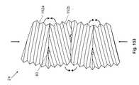
(詳細な説明)
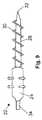
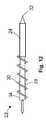
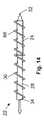
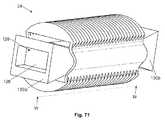
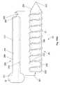
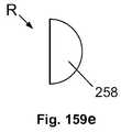
図5は、拡大可能な取り付けデバイス22が、近位端に拡大可能でないセクション28、この拡大可能な取り付けデバイス22に沿って中間長さに拡大可能なセクション24、および遠位端34を有し得ることを示す。この拡大可能な取り付けデバイス22のその他の改変例では、拡大可能でないセクション28は、拡大可能なセクション24の遠位方向にあり、そして/またはこの拡大可能な取り付けデバイス22は、1つ以上の拡大可能なセクション24および/または互いと散在され得る拡大可能でないセクション28を有し得る。(Detailed explanation)
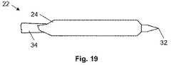
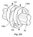
FIG. 5 shows that the
この拡大可能な取り付けデバイス22は、拡大可能な取り付けデバイス22の軸を有し得る。拡大可能なデバイスの軸26は、実質的に真っ直ぐであるか、または湾曲し得る。 The
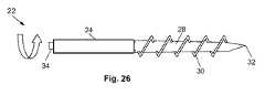
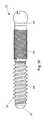
拡大可能な取り付けデバイス22の近位端は、先端部32を有し得る。この先端部32は、鋭いか、またはそうでなければ骨228中に拡大可能な取り付けデバイス22を着座させる形態である(例えば、切断歯を有する)。拡大可能でないセクション28は、例えば、拡大可能なデバイス22を骨228中にねじ込む形態の、拡大可能でないねじ30を有し得る。 The proximal end of the
図5は、拡大可能なデバイス22が、半径方向に縮小した形態を有し得ることを示す。図6は、拡大可能な取り付けデバイス22が、半径方向に拡大した形態を有し得ることを示す。例えば、拡大可能なセクション24は、矢印によって示されるように半径方向に拡大され得る。 FIG. 5 shows that the
拡大可能なセクション24は、弾力的に、そして/または変形可能に拡大可能であり得る。拡大可能なセクション24は、軸方向圧縮(例えば、図8〜11を参照のこと)、回転(例えば、図26〜29を参照のこと)、ウェッジ130、ランプ110またはジャッキ(例えば、図58〜64を参照のこと)、またはそれらの組み合わせにより、半径方向に拡大され得る。 The
拡大可能なセクション24は、付勢されて弾力的に半径方向に拡大され得る。例えば、拡大可能なセクション24は、自己拡大可能または解放可能なスプリングであり得る。拡大可能なセクション24は、弾力的に半径方向に拡大可能であり得、そして弾力的拡大単独によって達成される、より大きな半径までさらに変形により半径方向に拡大可能であり得る。 The
拡大可能なセクション24は、この拡大可能なセクション24が半径方向に拡大した形態にあるとき、それから半径方向に延びる1つ以上のアンカーを有し得る。これらアンカーは、無頭釘、フック、ピン、歯、ファスナー、釘152、ねじ、串、スパイク、杭、またはそれらの組み合わせであり得る。 The
図7は、拡大可能な取り付けデバイス22の軸が湾曲し得ることを示す。この拡大可能な取り付けデバイス22の軸は、湾曲した長さおよび真っ直ぐな長さを有し得る。例えば、この拡大可能な取り付けデバイス22の軸は、拡大可能でないセクション28および遠位端34に沿った実質的に真っ直ぐな長さ、および拡大可能なセクション24に沿った湾曲長さを有し得る。 FIG. 7 shows that the axis of the
図8および図9は、拡大可能な取り付けデバイス22が、図8の矢印によって示されるように遠位端34に近位端に向かう力132を付与することにより半径方向に拡大され得ることを示す。この近位端に向かう力132は、拡大可能な取り付けデバイス22の軸に実質的に平行であり得る。この近位の力132は、例えば、骨228および/または配備ツール60により付与される遠位の力132によって対向され得る。拡大可能なセクション24は、次いで、図9に矢印で示されるように半径方向に拡大する。 8 and 9 show that the
図10および11は、拡大可能な取り付けデバイス22が、拡大可能なセクション24上の拡大可能なねじ66、および拡大可能でないセクション28上に拡大可能でないねじ30を有し得ることを示す。拡大可能なねじ66は、拡大可能なセクション24上の残りの部分とともに半径方向に拡大し得る。図10および11に示される拡大可能な取り付けデバイス22は、図8および9に示されるような方法によって半径方向に拡大され得る。 FIGS. 10 and 11 show that the
図12および13は、拡大可能な取り付けデバイス22が、矢印によって示されるように遠位端34に遠位端に向かう力132を付与することにより半径方向に拡大され得ることを示す。この遠位端に向かう力132は、拡大可能な取り付けデバイス22の軸に実質的に平行であり得る。この遠位端の力132は、骨228および/または配備ツール60によって付与される近位端の力132によって対向され得る。拡大可能なセクション24は、次いで、図13に矢印によって示されるように半径方向に拡大し得る。 12 and 13 show that the
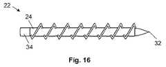
図14および15は、拡大可能な取り付けデバイス22が、拡大可能なセクション24上に拡大可能なねじ66、および拡大可能でないセクション28上に拡大可能でないねじ30を有し得ることを示す。この拡大可能なねじ66は、拡大可能なセクション24上の残りの部分とともに半径方向に拡大し得る。図14および15に示される拡大可能な取り付けデバイス22は、図12および13に示されるような方法によって半径方向に拡大され得る。 FIGS. 14 and 15 show that the
図16は、拡大可能な取り付けデバイス22の実質的に全体の長さが拡大可能なセクション24であり得ることを示す。遠位端34は、拡大可能セクション24から遠位に延びる。図17は、全体の拡大可能なセクション24が半径方向に拡大し得ることを示す。図16および17は、拡大可能なセクション24が拡大可能なねじ66を有し得ることを示す。図18および19は、拡大可能なねじ66なしで図16および17の拡大可能な取り付けデバイス22の改変例を示す。 FIG. 16 shows that the substantially entire length of the
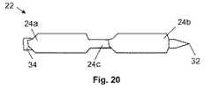
図20は、拡大可能な取り付けデバイス22が、遠位から近位まで、第1の拡大可能なセクション24a、第3の拡大可能なセクション24c、および第2の拡大可能なセクション24bを有し得ることを示す。これら第1、第2および第3の拡大可能なセクション24は、異なる割合で半径方向に拡大し得る(異なる配備負荷の下、例えば、1つ以上が弾力性により、そして1つ以上が変形により拡大可能である)。例えば、第1および第2の拡大可能なセクション24a、24bが同じ割合で半径方向に拡大可能であり、そして第3の拡大可能なセクション24cがより少ない割合で半径方向に拡大し得る。 FIG. 20 shows that the
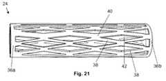
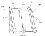
図21は、拡大可能なセクション24がジョイント40で互いに取り付けられる多数の支柱38を有し得ることを示す。拡大可能なセクション24から半径方向に縮小した形態にあるとき、支柱38は、ダイアモンド形状のポート42を形成するような形態であり得る。この拡大可能なセクション24は、遠位端34に末端フープ36aおよび/または近位端に末端フープ36bを有し得る。これらフープ36は、個々の端部ですべての支柱38に取り付けられ得る。これらフープ36と支柱38は、すべて互いと一体であり得、そして/または互いに取り付けられ得る。 FIG. 21 shows that the
図22は、長手方向の圧縮力44が拡大可能なセクション24に付与され得、例えば、半径方向の拡大46を生じる。半径方向に拡大した形態では、支柱38はジョイント40の近傍で変形し得る。フープ36は、実質的に変形しないままであり得る。 FIG. 22 shows that a longitudinal
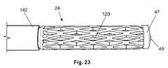
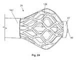
図23および24は、拡大可能なセクション24が、この拡大可能なセクション24を長手方向に圧縮することにより半径方向に拡大され得ることを示す。例えば、配備ツール60(または拡大可能な取り付けデバイス22)は、アンビル142および配備キャップ47を有し得る。このアンビル142は、遠位端34および/または拡大可能でないセクション28であり得る。配備キャップ47は、例えば、アンビル142とは反対の、拡大可能でないセクション28および/または遠位端34の一部であり得るか、またはそれらに取り付けられ得る。拡大可能なセクション24は、アンビル142と配備キャップ47との間で圧縮され得る。 FIGS. 23 and 24 show that the
配備ツール60(または拡大可能な取り付けデバイス22)は、配備ロッド128を有し得、例えば、圧縮力132を配備キャップ47に伝達する。配備ロッド128は、例えば、離脱可能な配備アンカー49により、配備キャップ47に離脱可能に取り付けられ得る。離脱可能な配備アンカー49は離脱され得、そしてこの配備ロッド128は、拡大可能なセクション24が半径方向に拡大された後、除去され得る。 The deployment tool 60 (or expandable attachment device 22) may have a
図25a〜eは、拡大可能なセクション24の支柱38、ポート42およびジョイント40の形態の改変例を示す。図25aは、ポート42が、端部領域52におけるより、拡大可能なセクション24の長手方向の中央近傍の中心領域54近傍でより大きくあり得ることを示す。より大きなポート42を備えた拡大可能なセクション24の長さは、より小さなポート42をもつ拡大可能なセクション24の長さの前に、長手方向圧縮44の期間に半径方向に拡大し得る。この拡大可能なセクション24は、1つの端部または両方の端部でねじ50および/またはその他の離脱可能な取り付け形態を有し得る。この拡大可能なセクション24は、この拡大可能なセクション24の近位端を通って配備ツール60(例えば、配備ロッド128)を受容する形態のツールポート48を有し得る。 FIGS. 25 a-e show a variation of the configuration of the
図25bは、支柱38とポスト42とが拡大可能なセクション24の全長に沿って実質的に同一であり得ることを示す。図25cは、主要支柱56、および複数の主要支柱56に取り付けられるより小さな折り畳まれた交差支柱58を有し得る。図25dは、支柱38およびポート42が拡大可能なセクション24の全長に沿って実質的に同一であり得、しかも、拡大可能なセクション24に対して、ポート42が角度のある方向におけるより長手方向でより長くあり得ることを示す。図25eは、支柱38およびポート42が拡大可能なセクション24の全長に沿って実質的に同一であり得、しかも、ポート42が、拡大可能なセクション24に対して、ポート42が角度のある方向におけるより長手方向において、より長くあり得、そして図25dに示されるようにより小さく、かつより多いことを示す。 FIG. 25 b shows that the
図26および27は、遠位端34および/または拡大可能なセクション24が、図26で矢印によって示されるように回転されるとき、拡大可能なセクション24が、図27で矢印によって示されるように半径方向に拡大し得ることを示す。図26および27は拡大可能なセクション24が、拡大可能でないセクション28に対して近位であり得ることを示す。 26 and 27 show that when the
図28および29は、遠位端34および/または拡大可能なセクション24が、図28で矢印によって示されるように回転されるとき、拡大可能なセクション24が、図29で矢印によって示されるように半径方向に拡大し得ることを示す。図28および29は拡大可能でないセクション28が、拡大可能なセクション24に対して近位であり得ることを示す。 28 and 29 show that when the
図30は、拡大可能なセクション24が、この拡大可能なセクション24を半径方向に通るスロット62を有し得ることを示す。このスロット62は、この拡大可能なセクション24に沿ってらせん形態を有し得る。遠位端34は、ねじ50であり得る。拡大可能な取り付けデバイス22は、配備ツール60に離脱可能に取り付けられ得る。 FIG. 30 shows that the
図31は、拡大可能なセクション24がテクスチャード加工表面を有し得ることを示す。拡大可能な取り付けデバイス22は、近位端に末端端部キャップ64を有し得る。この末端端部キャップ64は、実質的に球形形態である。 FIG. 31 shows that the
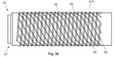
図32は、拡大可能なセクション24が、らせんスロット62および拡大可能なねじ66を有し得ることを示す。拡大可能なねじ66は、らせんスロット62とは実質的に反対の角度のらせんであり得る。拡大可能なねじ66は、拡大可能な取り付けデバイス22の軸に垂直な平面に対し正の角度または負の角度のらせんであり得る。らせんスロット62は、拡大可能なねじ66に対し、反対の徴候(すなわち、正または負)のらせんであり得る。 FIG. 32 shows that the
図32は、末端端部キャップ64の近位端が配備ツールアタッチメント68、例えば、キャップ64のヘッド上の交差ノッチを有し得ることを示す。この交差ノッチは、末端端部キャップ64を係合するために利用され得る。 FIG. 32 shows that the proximal end of the
中心シャフト80の遠位端34は、シャフト配備ツールアタッチメント70、例えば、アレンソケットまたは六角形ソケットまたは中隔(septagonal)ソケットを有し得る。 The
図34は、拡大可能なセクション24が半径方向に縮小した形態にあるとき、拡大可能なねじ66が、拡大可能な取り付けデバイス22の軸に対して拡大可能でないねじ30におけるのとほぼ同じ半径まで突出し得ることを示す。 FIG. 34 shows that when the
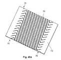
図35aおよび35bは、拡大可能なセクション24が、拡大可能な取り付けデバイス22の残りの部分に分離され得ることを示す。図35bは、らせんスロット62が、拡大可能なセクション24の壁184の厚みを通って延び得ることを示す。図36〜39は、拡大可能なセクション24のさらなる詳細を示す。 FIGS. 35 a and 35 b show that the
図38は、拡大可能なセクション24が、スロットのある壁セクション74中に多くのらせんスロット62を有し得る拡大可能なセクション壁72を有し得ることを示す。拡大可能なセクション壁72は、1つ以上のスロットのない壁セクション76を、例えば、拡大可能なセクション24の遠位端34および近位端に有し得る。スロット62は、このスロット62の1つの端部または両方の端部にジョイント40を有し得る。 FIG. 38 shows that the
図39は、ジョイント40が円形であり得ることを示す。このジョイント40は、スロット62の幅より大きな、より小さな、またはそれと等しい直径を有し得る。 FIG. 39 shows that the joint 40 can be circular. The joint 40 may have a diameter that is greater than, less than, or equal to the width of the
図40aおよび図40bは、拡大可能なセクションの壁72が1つ以上の逆行スロットセクション78、例えば、スロットのある壁セクション74の各端部に有し得ることを示す。この逆行スロットセクション78は、スロットのある壁セクション74の残りにあるスロット62とは実質的に反対の方向にあるスロット62を有し得る。主要(すなわち、逆行していない)スロット62は、拡大可能な取り付けデバイス22の軸に垂直な平面に対して正または負の角度のらせんであり得る。逆行スロットは、主要スロット62に対して反対の徴候(すなわち、正または負)のらせんであり得る。 40a and 40b show that the
逆行スロットセクション78は、例えば、衝撃吸収体として作用し得る。逆行スロットセクション78は、拡大可能なセクション24の最大半径方向拡大46を増加し得る。スロット62は、拡大可能なセクション24の長さに沿って正弦波状であり得る。 The
図40bは、スロット62の端部が、拡大可能なセクション24の端部から異なる長さで配置され得ることを示す。例えば、隣接するスロット62の長さを変えることは、拡大可能なセクション24条のひずみを拡散し得る。 FIG. 40 b shows that the end of the
図41〜45は、拡大可能なセクション24の寸法を示す(寸法は、アタッチレメントB上で示される)。 41-45 show the dimensions of the expandable section 24 (dimensions are shown on attachment B).
図41は、拡大可能でないセクション28が、中心シャフト80および遠位端34と一体であり得ることを示す。 FIG. 41 shows that the
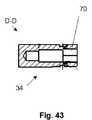
図43は、遠位端34が、それを通るシャフト配備ツールアタッチメント70を有し得ることを示す。 FIG. 43 shows that the
図46は、拡大可能でないセクション28、中心シャフト80および遠位端34の拡大を示す。 FIG. 46 shows an enlargement of the
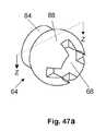
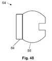
図47aおよび47bは、末端キャップ端部64がキャップボール88およびキャップスリーブ84を有し得ることを示す。キャップボール88および/またはキャップスリーブ84は、長さの全部または一部に沿って内部キャップねじ86を有し得る。 47a and 47b show that the
図48〜51は、拡大可能なセクション24の寸法を示す(寸法はアタッチメントC上で示される)。 48-51 show the dimensions of the expandable section 24 (dimensions are shown on attachment C).
図52は、拡大可能な取り付けデバイス22が、配備ツール60に離脱可能に取り付けられ得ることを示す。配備可能なツール60は、末端端部キャップ64と、例えば、キャップ配備ツールアタッチメント68において整列かつ相交わる配備係合歯90を有し得る。 FIG. 52 illustrates that the
図53は、拡大可能な取り付けデバイス22が、個別の要素に分解され得ることを示す。例えば、拡大可能でないセクション28は、中心シャフト80と一体であり得る。中心シャフト80は、例えば、遠位端34で、末端端部キャップ64に取り付けられ得るシャフトキャップアタッチメント82を有し得る。 FIG. 53 shows that the
図54は、拡大可能な取り付けデバイス22が、矢印によって示されるように、拡大可能なセクション24を中心シャフト80上で移動することによりアセンブルされ得ることを示す。末端端部キャップ64は次いで、矢印によって示されるように、シャフトキャップアタッチメント82上で回転され得る。 FIG. 54 shows that the
図55および56は、配備ツール60が、ポストツール100および歯ツール92を有し得ることを示す。歯ツール92は、ポストツール100と分離、それに取り付け、またはそれと一体であり得る。 55 and 56 show that the
ポストツール100は、ポストツールハンド102を有し得る。このポストツールハンド102は、配備係合ポスト96に取り付けられ得るか、またはそれと一体であり得る。ポストツール100は、配備ツールサスペンション98を有し得る。配備係合ポスト96は、シャフト配備ツールアタッチメント70に取り付けられる形態であり得る。 The
歯ツール92は、配備係合歯90を有し得る。この配備係合歯90は、キャップ配備ツールアタッチメント68に取り付けられる形態であり得る。歯ツール92は、例えば、歯ツール92の残りから半径方向に延びる、歯ツールハンドル94を有し得る。 The
配備ツールサスペンション98は、歯ツール92およびポストツール100を弾力性的に分離し得る。配備ツールサスペンション98は、配備係合ポスト96をポストツールハンドル102から吊し得る。 The
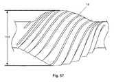
図57は、半径方向に拡大した形態にある拡大可能なセクション24が、約7mm(0.3インチ)〜約15mm(0.59インチ)、例えば約9.99mm(0.393インチ)または約9.31mm(0.367インチ)の外径を有し得ることを示す。 FIG. 57 illustrates that the
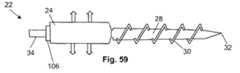
図58および59は、外部ウェッジ106が、図58中の矢印によって示されるように、拡大可能なセクション24中に挿入され得ることを示す。拡大可能なセクション24は次いで、図59中の矢印によって示されるように半径方向に拡大し得る。外部ウェッジ106は、拡大可能なセクション24中に残され得るか、または拡大可能なセクション24から除去され得る。ウェッジ130は、方形、丸(例えば、円錐形ウェッジ)、矩形、卵形、またはそれらの組み合わせである横断面を有し得る。 58 and 59 illustrate that the
図60は、拡大可能な取り付けデバイス22が、第1の外部ウェッジ106aおよび第2の外部ウェッジ106bを有し得ることを示す。第2の外部ウェッジ106bは、拡大可能でないセクション28に取り付けられ得るか、またはそれと一体であり得、そして/またはそうでなければ、拡大可能なセクション24が半径方向に縮小した形態にあるとき、拡大可能なセクション24と拡大可能でないセクション28との間に位置決めされる。第2の外部ウェッジ106bは、拡大可能な取り付けデバイス22の遠位端34にはじめに向かう尖った狭い端部であり得る。 FIG. 60 shows that the
近位端に向かう力が、矢印によって示されるように第1の外部ウェッジ106aおよび/または遠位端34に付与され得る。拡大可能なセクション24は次いで、ウェッジ130が拡大可能なセクション24中のチャンネル中に押されるとき、図61に矢印によって示されるように、半径方向に拡大し得る。 A force toward the proximal end may be applied to the first
図62は、拡大可能な取り付けデバイス22が、第1の拡大可能なセクション24a、第2の拡大可能なセクション24b、および第3の拡大可能なセクション24cを有し得ることを示す。この拡大可能なセクション24は、図58〜61に示されるように、各々が内部中空またはチャンネル中に入る1つまたは2つの外部ウェッジ106を有し得る。 FIG. 62 shows that the
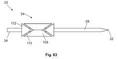
図63は、拡大可能なセクション24が、半径方向に拡大する形態の1つ以上の拡大要素108を有し得ることを示す。この拡大可能なセクション24は、1つ、2つまたはより多くの内部ウェッジ112を有し得る。拡大要素108は、内部ウェッジ112が拡大要素108中に圧縮されるとき、内部ウェッジ112をスライド可能に係合する形態のランプ110を有し得る。 FIG. 63 shows that the
図64は、内部ウェッジ112が、矢印によって示されるように、拡大要素108中に圧縮され得ることを示す。拡大要素108は次いで、矢印によって示されるように半径方向に拡大し得る。 FIG. 64 shows that the
図65は、内部ウェッジ112が、ランプ110と干渉ばめし得ることを示す。内部ウェッジ112がさらに圧縮されるとき、この内部ウェッジ112は、拡大要素108の変形またはその他の移動を引き起こし得る。 FIG. 65 shows that the
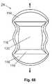
図66および67は、拡大可能なセクション24が、2つの側壁116によって連結される上壁114および底壁118を有し得ることを示す。上壁114および底壁118は、拡大可能なねじ66を有し得る。側壁116は、拡大可能なねじ66を有し得る。上壁114および/または底壁118は、拡大可能なセクション24の長手方向チャンネル120中に内方に延びる1つ以上のランプ110を有し得る。 66 and 67 illustrate that the
図68は、半径方向に拡大した形態で、上壁114および底壁118が、矢印によって示されるように、半径方向の外方に移動し得ることを示す。側壁116は、変形そして/または半径方向の内方に移動し得る。 FIG. 68 shows that in a radially expanded configuration, the
図69は、上壁114および/または底壁118が、実質的に長手方向にそれを通って完全または部分的に通過する操作チャンネル122を有し得ることを示す。この操作チャンネル122は、例えば、円筒形であり得る。 FIG. 69 shows that the
図70は、上壁114および/または底壁118が、長手方向のガイドスロット124を有し得ることを示す。このガイドスロット124は、長手方向チャンネル122と流体連通し得る。このガイドスロット124は、ランプ110と平行であり得る。 FIG. 70 illustrates that the
図71および72は、第1のウェッジ130aおよび第2のウェッジ130bが、拡大可能なセクション24の長手方向チャンネル122中に挿入され得ることを示す。第2のウェッジ130bおよび/または第1のウェッジ130aは、配備ロッド128と一体であり得る。第1のウェッジ130aは、長手方向のウェッジチャンネル126を有し得る。配備ロッド128は、ウェッジチャンネル126を通って第1のウェッジ130aにスライド可能に取り付けられ得る。第1のウェッジ130aおよび第2のウェッジ130bは、個々のランプ110に実質的に一致する形態を有し得る。 71 and 72 show that a
図73は、対向する圧縮の第1および第2の並進運動力132が、第1のウェッジ130aおよび配備ロッド128にそれぞれ付与され得ることを示す。第1のウェッジ130aおよび第2のウェッジ130bは、拡大可能なセクション24の中に変形して移動され得る。 FIG. 73 shows that opposing compressive first and second translational forces 132 can be applied to the
図74は、拡大可能なセクション24が、例えば、拡大可能なセクション24の端部の近傍で、そして/またはウェッジ130が挿入される長さまで半径方向に拡大し得ることを示す。 FIG. 74 illustrates that the
図75は、拡大可能なセクション24およびウェッジ130が一方の側でのみ半径方向に拡大する形態であり得ることを示す。例えば、ウェッジ130は、ウェッジ130の1つの側で角度をなすスロープを、そして角度のあるスロープの反対側に平坦な側面を有し得る。拡大可能なセクション24は、壁184を、半径方向に拡大される側にテーパー状の厚みをもつ壁184、および一定厚みの壁184そして/またはテーパー状の壁184とは反対側にテーパー状の壁184より厚い壁184として有し得る。 FIG. 75 illustrates that the
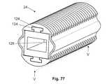
図76は、ウェッジ130がウェッジレール134を有し得ることを示す。ウェッジレール134は、ガイドスロット124と整列し、そしてその中に挿入し得る。図77および78は、ウェッジレール134がガイドスロット124にスライド可能に取り付けられ得ることを示す。 FIG. 76 shows that the
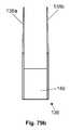
図79a〜79dは、操作ツール136がベース140、ベース140から延びる第1の脚138a、およびベース140から延びる第2の脚138bを有し得ることを示す。脚138は、拡大可能なセクション24の操作チャンネル122中に適合するように構成され得る。脚138は、操作チャンネル122中に挿入するために用いられ得、そして拡大可能なセクション24を操作(例えば、並進運動、回転、変形)する。脚138は、ベース140に対して関節運動し得る。脚138も関節運動は、ハンドル224またはトリガーのような、ベース140上のコントロール(図示はしていない)によって制御され得る。 79a-79d show that the
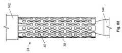
図80は、コーン144またはマンドレル188が、支柱38およびジョイント40を有する拡大可能なセクション24の長手方向チャンネル120中に並進運動され得ることを示す。この拡大可能なセクション24は、フープ36を有さなくてもよい。この拡大可能なセクション24は、コーン144の反対の端部にアンビル142を有し得る。 FIG. 80 shows that the
図81は、コーン144がアンビル142に向かって押され得、そして/またはアンビル142がコーン144に向かって押され得、長手軸チャンネル120を通って、アンビル142に向かうコーン144の矢印200によって示されるような長手方向の移動を生じることを示す。例えば遠位端34におけるコーン144上の拡大可能なセクション24は、矢印によって示されるように半径方向に拡大し得る。 81 illustrates that
図82は、コーン144が拡大可能なセクション24の全長に沿って長手方向に移動され得ることを示す。コーン144は、アンビル142中に受容され得る。拡大可能なセクション24の全長は、矢印によって示されるように半径方向に拡大し得る。この拡大は、弾力性および/または変形可能であり得る。コーン144は、除去され得るか、またはその場に残り得る。 FIG. 82 shows that the
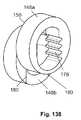
図83は、拡大可能なセクション24が、ジョイント40および/または支柱38と一体であり得るか、またはそれに取り付けられ得るプレート146を有し得ることを示す。これらプレート146は、拡大可能なセクション24の残りに柔軟に取り付けられるか、またはそれらと一体である形態であり得る。各プレート146は、各ポート42を実質的に覆う形態であり得る。 FIG. 83 illustrates that the
図84は、第1のプレート146aおよび第2のプレート146bがポート42を覆い得ることを示す。第1のプレート146aは、ポート42に隣接する第1のジョイント40aから延び得る。第2のプレート146bは、第1のプレート146aに対向するジョイント40から延び得る。 FIG. 84 shows that the
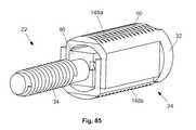
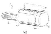
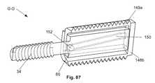
図85〜87は、第2の拡大可能な要素148bに直接または間接的にスライド可能に取り付けられた第1の拡大可能な要素148aを有し得る拡大可能なセクション24を有し得る拡大可能な取り付けデバイス22を示す。例えば、第1の拡大可能な要素148aは、中心シャフト80にスライド可能に取り付けられ得、中心シャフト80が遠位方向に移動させられるとき上方に移動し、そして第2の拡大可能な要素148bは、中心シャフト80にスライド可能に取り付けられ得、中心シャフト80が遠位方向に移動させられるとき下方に移動する。拡大可能な取り付けデバイス22が半径方向に縮小された形態にあるとき、中心シャフト80は、拡大可能な要素148の実質的に内側にあり得る。拡大可能な取り付けデバイス22が半径方向に拡大した形態にあるとき、中心シャフト80は、拡大可能な要素148の実質的に外側にある。 85-87 are expandable that may have an
第1の拡大可能な要素148aは先端部32を有し得る。この先端部32は、尖っているか、そして/または平坦であり得る。第1の拡大可能な要素148aは、頂部側にねじ50を有し得る。第1の拡大可能な要素148aは、半径方向の内方に延び得るペグ152(図87に示される)を有し得る。ペグ152は、中心シャフト80の側面上の第1のトラック150a中をスライドする形態であり得る。第1のトラック150aは、遠位方向で低くから近位方向で高くまで延び得る。 The first
第2の拡大可能な要素148bは、底面にねじ50を有し得る。第2の拡大可能な要素148bは、第1の拡大可能な要素148aのそれと類似の半径方向の内方に延び得るペグ152を有し得る。このペグ152は、第1のトラック150aの側とは反対の中心シャフト80の側面上の第2のトラック150b中をスライドする形態であり得る。第2のトラック150bは、遠位方向で高くから近位方向で低くまで延び得る。 The second
図88は、拡大可能な取り付けデバイス22が半径方向に拡大した形態にあるとき、第1の拡大可能な要素148aが第2の要素から分離され得ることを示す。 FIG. 88 shows that the first
中心シャフト80が拡大可能なセクション24から引から出されるとき、第1の拡大可能な要素148aのペグ152は上方に押され得、第1の拡大可能な要素148aを上方に押す。中心シャフト80が拡大可能なセクション24から引き出されるとき、第1の拡大可能な要素148aのペグ152は、図88に矢印によって示されるように上方に押され得、第2の拡大可能な要素148bを下方に押す。 When the
中心シャフト80が拡大可能なセクション24から引き出されるとき、第2の拡大可能な要素148bのペグ152は下方に押され得、図88中矢印で示されるように、第2の拡大可能な要素148bを下方に押す。 When the
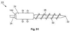
図94は、拡大可能な要素142デバイスが、側方視野から実質的に三角形であり得ることを示す。この拡大可能な要素142は互いにスライド可能に取り付けられ得る。拡大可能な取り付けデバイス22は、複数の拡大可能な要素148を有し得る。例えば、遠位端34および/または遠位の拡大可能な要素148に付与される近位端に向けられる力132を含む圧縮力132は、拡大可能な要素148を押し得、矢印によって示されるように半径方向に拡大する。 FIG. 94 shows that the
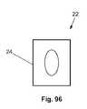
図95は、拡大可能な取り付けデバイス22の遠位端34、例えば、先端部32が、丸い、円形、卵形、方形、矩形、三角形、またはそれらの組み合わせであり得る横断面を有し得ることを示す。拡大可能なセクション24は、丸い、円形、卵形、方形、矩形、三角形、またはそれらの組み合わせであり得る横断面を有し得る。図96は、拡大可能なセクション24の改変例を示す。 FIG. 95 shows that the
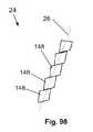
図97は、半径方向に縮小した形態にある拡大可能なセクション24が直線状の拡大可能なセクションの軸26を有し得ることを示す。図98は、半径方向に拡大した形態にある拡大可能なセクション24が、直線状のまたは湾曲した拡大可能なセクションの軸26を有し得、そして/または拡大可能なセクションの軸26が、半径方向に縮小した形態にある拡大可能なセクションの軸26に対して角度をなし得ることを示す。 FIG. 97 illustrates that the
図99および100は、拡大可能なセクション24が、それを通るスライド可能に取り付けられた中心シャフト80を有する一連の拡大可能な要素148を有し得ることを示す。中心シャフト80は、中心シャフトアンカー156を有し得る。中心シャフトアンカー156は、長手方向チャンネル120の直径より大きな直径を有し得る。歯154は、拡大可能な要素148、例えば、示されるように、交互する拡大可能な要素148の少なくとも対向する側面から半径方向に延び得る。 FIGS. 99 and 100 show that the
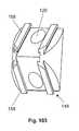
図101および102は、拡大可能な要素148がガイドレール158を有し得ることを示す。ガイドレール158は、隣接する拡大可能な要素148上の受容要素にスライド可能に取り付けられ得る。少なくともその他の拡大可能な要素148毎にある長手方向チャンネル120が横方向に細長くあり得る。 101 and 102 show that the
図103および104は、拡大可能な要素が、アセンブルされるとき、別の拡大可能な要素に隣接する各表面上に1つまたは2つのガイドレール158を有し得ることを示す。個々の拡大可能な要素中の長手方向チャンネル120の断面は、例えば、円形、卵形、方形、矩形、またはそれらの組み合わせであり得る。 103 and 104 show that an expandable element can have one or two
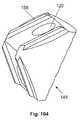
図105は、拡大可能な要素148が、アセンブルされるとき、別の拡大可能な要素に隣接する各表面上に2つ以上のガイド溝160を有し得ることを示す。このガイド溝160は、ガイドレール158にスライド可能に取り付けられ得る。 FIG. 105 shows that the
図106は、拡大可能な要素148が1つ以上の輪郭チャンネル162を有し得ることを示す。輪郭チャンネル162は、拡大可能な要素148内に、画定され、実質的に閉じた容量であり得る。輪郭チャンネル162は、例えば、使用の間に歯154に対して付与される力に起因して変形し得る。変形されるとき、輪郭チャンネル162は、例えば、移植されるとき、非変形形態にある拡大可能な要素148と比較して、隣接組織に付与される応力を低減し得る。 FIG. 106 illustrates that the
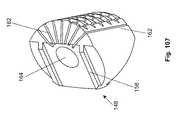
図107は、拡大可能な要素のチャンネル164から半径方向に離れて延びる、多くの輪郭チャンネル162を有する拡大可能な要素148を示す。この輪郭チャンネル162は、拡大可能な要素148の外側に開くスロットとしての形態であり得る。 FIG. 107 shows an
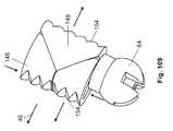
図108は、末端端部キャップ64が、最遠位の拡大可能な要素148の末端にあり得ることを示す。例えば、末端端部キャップ64は、中心シャフトアンカー156であり得るか、またはそれに取り付けられ得る。 FIG. 108 shows that the
図109は、矢印によって示されるように、長手方向の圧縮力が、末端端部キャップ64を介して送達され得ることを示す。この拡大可能な要素148は、次いで、矢印によって示されるように半径方向に拡大し得る。 FIG. 109 shows that a longitudinal compressive force can be delivered through the
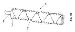
図110および111は、9および5個の拡大可能な要素148をそれぞれ有する拡大可能なセクション24を示す。 110 and 111 show an
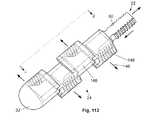
図112および113は、中心シャフト80が、1つ以上の交互する対向して面する一体ウェッジ112を有する形態であり得ることを示す。拡大可能なセクション24は、1つ以上の拡大可能な要素148を有し得る。拡大可能な要素148は、近位端上にガイドレール158、および遠位端34上にガイド溝160を有し得る。ガイド溝160およびガイドレール158は、単一の自由度に、拡大可能な要素148間の相対的運動(例えば、側方運動)を拘束し得る。拡大可能な要素148の内表面は、一体ウェッジ112を接する形態であり得る、交互に対向して面する内部ランプ166を有し得る。 112 and 113 illustrate that the
図113は、中心シャフト80が拡大可能なセクション24に対して移動され得、例えば、中心シャフト80が、拡大可能なセクション24から移動され得ることを示す。この拡大可能な要素148は、次いで、矢印によって示されるように、隣接する拡大可能な要素148とは反対の方向に、半径方向に拡大し得る。 FIG. 113 shows that the
図114は、拡大可能な要素148が、この拡大可能な要素148の遠位端34に1つまたは2つのガイド溝160を有し得ることを示す。このガイド溝160は、長手方向チャンネル120の周りの壁にあるノッチであり得る。この拡大可能な要素148は、この拡大可能な要素148の遠位端に1つまたは2つのガイドレール158を有し得る。ガイドレール158は、1つの拡大可能な要素148が別の拡大可能な要素148上に積み上げられるとき、ガイド溝160にスライド可能に取り付けられる形態であり得る。 FIG. 114 shows that the
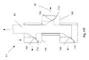
図115は、内部ランプ166が長手方向チャンネル120の内表面上のスロープであり得ることを示す。ねじ50が、拡大可能な要素148の1つの側面上に存在し得る。 FIG. 115 shows that the
図116および117は、図117に矢印で示されるように、拡大可能な要素148の内部ランプ166に中心シャフト80の内部ウェッジ112が押されるとき、拡大可能な要素148が、矢印によって示されるように、内部ウェッジ112によって半径方向外方に押され得ることを示す。 116 and 117 show that when the
図118は、拡大可能なセクション24が、カムまたはその他のオフセット−回転要素であり得る、第1、第2、第3およびそれより多い拡大可能な要素148a、148b、148cを有し得ることを示す。図119は、遠位端34が矢印によって示されるように回転され得ることを示す。拡大可能な要素148は、次いで、矢印によって示されるように、半径方向に移動するか、または拡大し得る。この拡大可能な要素148は、異なるタイミングで移動し得る。 FIG. 118 illustrates that the
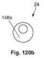
図120aは、拡大可能な要素148が、この拡大可能な要素148を通って延びる中心シャフト80を有し得ることを示す。この中心シャフト80は、拡大可能な取り付けデバイス22の軸に対して横断方向にある平面中の拡大可能な要素148の領域の中心からオフセットされ得る。 120a shows that the
図120bは、半径方向に縮小した形態にある拡大可能なセクション24が、拡大可能な取り付けデバイス22の軸に沿って実質的に整列させられたすべての拡大可能な要素148を有し得ることを示す。 FIG. 120 b shows that the
図120cは、拡大可能なセクション24が、中心シャフト80を回転すること、および/または中心シャフト80の周りで拡大可能な要素148を回転することにより半径方向に拡大され得ることを示す。拡大可能な要素148は、外に広がり、半径方向に拡大し得る。 FIG. 120 c shows that the
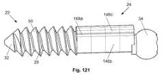
図121は、拡大可能な取り付けデバイス22が、中心シャフト80に偏心して取り付けられ、そして/または丸い突出部(ローブのある)形態を備えた複数の拡大可能な要素148を有し得ることを示す。 FIG. 121 shows that the
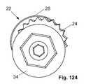
図122〜124は、拡大可能な取り付けデバイス22が、中心シャフト80(図示はされていない)に偏心して取り付けられた1〜4個の拡大可能な要素148を有し得ることを示す。この拡大可能な要素148は、拡大可能な要素148から半径方向に延びる歯154を有し得る。 122-124 illustrate that the
図125〜127は、半径方向に拡大した形態にある偏心して取り付けられた拡大可能な要素148を備えた拡大可能な取り付けデバイス22を示す。 125-127 show the
図128および129は、拡大可能なセクション24が、第1、第2および第3の拡大可能な要素148a、148b、148cを有し得ることを示す。この拡大可能な要素148は、相互ロックするレール110およびトラック150によってスライド可能に取り付けられ得る。このレール110およびトラック150は、隣接する拡大可能な要素148間の相対的運動を1つの自由度(例えば、垂直方向の相対運動)に拘束し得る。 128 and 129 show that the
拡大可能な要素148は、例えば、示されるように、複数の突出部をもつ中心シャフト80を受容する形態である長手方向のチャネル120を有し得、そして図128〜133に示されるように制御可能である。各々の拡大可能な要素148における長手方向チャンネル120の形態は、その他の拡大可能な要素148と同じか、または異なり得る。例えば、第1の拡大可能な要素148aおよび第3の拡大可能な要素148cは、実質的に同じ形態の長手方向チャンネル120を有し得る。第2の拡大可能な要素148bは、第1の拡大可能な要素148aの長手方向チャンネル120の水平方向に逆の形態であるような形態である長手方向チャンネル120を有し得る。第2の拡大可能な要素148bは、第1の拡大可能な要素148aの長手方向チャンネル120の約180゜回転である形態の長手方向チャンネル120を有し得る。中心シャフト80は、第1の突出部168aおよび第2の突出部168bを有し得る。 The
図130および131は、中心シャフト80が矢印によって示されるように回転させられ得ることを示す。中心シャフト80が回転させられると、突出部168は、拡大可能な要素148に対して力を及ぼし得る。拡大可能な要素148は、中心シャフト80の長手方向軸に実質的に垂直な方向に移動させられ得る。例えば、第1および第3の拡大可能な要素148a、148cは、矢印によって示されるように上方に向かって移動し得る。第2の拡大可能な要素148bは、矢印によって示されるように下方に移動し得る。 130 and 131 illustrate that the
図132および133は、中心シャフト80が、図130および131に示されるのとは反対方向に回転させられ得ることを示す。拡大可能な要素148は、図131から示されるのとは反対方向に移動し得る。 132 and 133 show that the
図134および135は、中心シャフト80が、中心シャフト80の長さに沿って、交互する第1の突出部168aおよび第2の突出部168bを有し得ることを示す。第1の突出部168aは、第1の突出部の軸170aを有し得る。第2の突出部168bは、第2の突出部の軸170bを有し得る。同じ平面でみるとき、第1の突出部の軸170aと第2の突出部の軸170bとの間の角度は、突出部の角度172であり得る。この突出部の角度172は、約90゜〜約180゜であり得る。第1の突出部168aは、第2の突出部168bとは反対の回転方向に作動され得る。 134 and 135 illustrate that the
図136は、中心シャフト80が回転させられるとき、第2の拡大可能な要素148bとは反対方向に移動し得る第1の拡大可能な要素148aを有し得る拡大可能なセクション24を示す。第1の拡大可能な要素148aは、第1の要素の歯176aを有し得る。第2の拡大可能な要素148bは、第2の要素の歯176bを有し得る。この第2の要素の歯176は、長手方向チャンネル120中で半径方向内方に延び得る。第1の要素の歯176aは、第2の要素の歯176bとは長手方向チャンネル120の反対側に存在し得る。中心シャフト80は、半径方向外方に延びるギア歯174を有し得る。このギア歯174は、第1の要素の歯176aおよび第2の要素の歯176bと係合し得る。 FIG. 136 shows the
図137〜139は、中心シャフト80が回転させられるとき、第1の拡大可能な要素148aが、第2の拡大可能な要素148bが下方に移動し得るのと同じ速度で上方に移動し得ることを示す。 FIGS. 137-139 show that when the
図140は、拡大可能なセクション24の壁184から半径方向に延びる1、2、3個またはそれより多い背骨186上にねじ50または歯154を有し得る拡大可能なセクション24を示す。半径方向に縮小した形態では、壁184は、複数の折り畳み182、例えば、各々2つの隣接する背骨186間に2つの折り畳み182を有し得る。折り畳み182は、隣接する背骨186間で不均一に間隔を置かれ得る。 140 shows the
図141は、壁184が、各々2つの隣接する背骨186間に2つの折り畳み182を有し得ることを示す。折り畳み182は、隣接する背骨186間で均一に間隔を置かれ得る。 FIG. 141 shows that the
図142は、壁184が隣接する背骨186間に1つの折り畳み182を有し得ることを示す。背骨186は、壁184から半径方向内方および/または外方に延び得る。 FIG. 142 illustrates that the
図143および144は、拡大可能なセクション24(例示の目的のために図141の拡大可能なセクション24として示される)が、拡大可能な取り付けデバイス22の中心シャフト80上に載せられ得ることを示す。この拡大可能なセクション24は、拡大可能な取り付けデバイス22上の第1の円錐144aと第2の円錐144bとの間に置かれ得る。拡大可能な取り付けデバイス22は、マンドレル188を有し得る。第2の円錐144bは、マンドレル188の一部であり得る。 FIGS. 143 and 144 illustrate that the expandable section 24 (shown as the
図145は、マンドレル188が、矢印によって示されるように、拡大可能なセクション24に向かって押され得ることを示す。この拡大可能なセクション24は、矢印によって示されるように半径方向に拡大し得る。 FIG. 145 shows that the
遠位端34は、固定化ロッド14またはプレート220のような別個のデバイスに取り付けられる形態であり得る。遠位端34はねじ50であり得る。 The
図146は、拡大可能な取り付けデバイス22が第1の拡大可能なセクション24aおよび第2の拡大可能なセクション24bを有し得ることを示す。各々の拡大可能なセクション24は、第1の円錐144aと第2の円錐144bとの間にあり得、そして図145に示されるのを含む、本明細書で記載されるように、半径方向に拡大され得る。 FIG. 146 shows that the
図147〜149は、拡大可能な取り付けデバイス22の中心シャフト80上に載せられた、図140〜142の拡大可能なセクション24をそれぞれ示す。 FIGS. 147-149 illustrate the
図150および153は、拡大可能なセクション24がほぼ4つの角度をなすポート42を有し得ることを示す。各ポート42は、ジョイント40を有し得る。2つの隣接するポート42の間に、個々の拡大可能なセグメント192、例えば、示されるような第1の拡大可能なセグメント192aおよび第2の拡大可能なセグメント192bが存在し得る。 FIGS. 150 and 153 illustrate that the
図152は、矢印によって示されるような長手方向圧縮力が、拡大可能なセクション24に付与され得ることを示す。拡大可能なセグメント192は、矢印によって示されるように、隣接するジョイント40の周りを回転し得る。ポート42は閉鎖し得る。半径方向に拡大した形態では、拡大可能なセクション24は、近位端から側方にシフトされる遠位端34を有し得る。 FIG. 152 illustrates that a longitudinal compressive force as indicated by the arrows can be applied to the
図153は、拡大可能なセクション24がより大きなポート42を有し得、そしてて/または拡大可能なセクション24が過剰に圧縮され得、ポート42が閉じた後に変形を引き起こすことを示す。遠位端34および拡大可能なセクション24の近位端は、側方が整列させられ得る。 FIG. 153 shows that the
図154aおよび154bは、取り付けデバイス22が外側殻252および内側構造258を有し得ることを示す。この内側構造258は、端部キャップ64およびこの端部キャップ64から延びるシャフトを有し得る。デバイス22がアセンブルされた形態にあるとき、シャフトは、外側殻252中に存在し得る。端部キャップ64は、シャフト配備ツールアタッチメント70を有し得る。 FIGS. 154a and 154b show that the
中空チャンネル260は、デバイス22の長手方向軸に沿って部分的または完全に延び得る。この中空チャンネル260は、端部キャップ64と、例えば、シャフト配備ツールアタッチメント70と流体連通し得る。 The
外側殻252は、拡大可能なセクション24および拡大可能でないセクション28を有し得る。拡大可能なセクション24は、通常の使用の間に拡大され得るか、または拡大されない(すなわち、改変例に依存して、この拡大可能なセクション24は拡大してもよいし、しなくてもよい)。 The
拡大可能なセクション24は、拡大可能なねじ30を有し得る。拡大可能なねじ30は、通常の使用の間に拡大され得るか、または拡大されない。 The
先端部32は、鋭く(例えば、外傷性)、鈍く(例えば、非外傷性)、(示されるような)鋭くなることと平坦な末端端部との組み合わせ、またはそれらのその他の組み合わせであり得る。先端部32は、骨228中の拡大可能な取り付けデバイス22に固定して取り付けられるか、またはそれに座る。 The
このデバイス22は、1つ以上の切断歯254を有し得る。例えば、このデバイスは、デバイスの末端端部近傍に切断歯254を有し得る。切断歯254は、外側殻252表面から、長手方向軸から半径方向に離れるように延び得、そして/または切断歯254は、(例えば、外側殻252の隣接する壁に対して切断の半径を増加することなく)外側殻252の先端部近傍で半径方向の外側外部壁の一部分の除去によって形成され得る。切断歯254は、外側殻252の長さに沿って長手方向に延び得る。切断歯254は、骨を通って切断するような形態であり得る。 The
デバイス22は、1つ以上の遠位ポート256を有し得る。遠位ポート256は、中空の長さと流体連通し得る。中空チャンネル260および遠位ポート256は、それを通る充填剤の流れを可能にする形態であり得る。流動可能、分配可能、またはそうでなければ、十分に小さな粒子サイズ、またはそれらの組み合わせにある本明細書に記載される任意の材料のような充填剤の供給源が、この中空の長さの近位端と流体連通し得る。充填剤は、圧力下で中空の長さに送達され得る。
図154cおよび154dは、取り付けデバイス22が1つ以上の流れポート266を有し得ることを示す。この流れポート266は、内側構造258のカニューレとした中空の長さと流体連通し得る。この流れポート266は、外側殻252および/または内側構造258の壁を通過し得る。内側構造258の壁を通る流れポート266は、デバイス22が充填剤送達形態にあるとき、外側殻252の壁を通って流れポート266と整列し得る。流れポート266は、このデバイス22に沿ってランダムまたは均一に分布され得る。例えば、流れポート266は、流れポート266が0゜に設定されるとき、長手方向の軸に対して0゜、約120゜、および約240゜の相対角度で角度をなして位置決めされ得る。 FIGS. 154c and 154d illustrate that the
充填剤、ロックまたは設定流体、エポキシ、本明細書に開示される任意の材料、またはそれらの組み合わせ(本明細書では、集合的に「充填剤」と称される)は、中空長さと流体連通する、シャフト配備ツールアタッチメント70および/または別個の充填剤取込みポートを通って送達され得る。この充填剤は、中空の長さを通って流れ得る。充填剤は、流れポート266および/または遠位ポート256を通って中空の長さを出得る。 Fillers, locks or setting fluids, epoxies, any material disclosed herein, or combinations thereof (collectively referred to herein as “fillers”) are in fluid communication with the hollow length. May be delivered through the shaft
図154eは、外側殻252および内側構造258が同軸の円筒であり得ることを示す。外側殻252と内側構造258との間のギャップは、実質的に流体密なインターフェースとして作用し得る。内側構造258は、外側殻252に対して軸方向および角度方向に(すなわち、回転可能に)スライド可能である。中空の長さは、外側殻252の遠位末端端部まで延び得る。中空の長さは、外側殻252の遠位末端端部で、外側殻252の遠位方向の環境と流体連通し得る。 FIG. 154e shows that the
図154fは、内側構造258と中空の長さが、外側殻252の遠位末端端部に到達する前に終結し得ることを示す。外側殻252の遠位末端端部は、中空の長さが、外側殻252の遠位末端端部で外側殻252の遠位方向の環境と流体連通することを妨げ得る。充填剤は、中空の長さを通って送達され得、外側殻252の遠位端を通ってではなく、外側殻252の側方壁中の流れポート266を通って、処置部位に送達され得る。 FIG. 154 f shows that the
図154gは、デバイスが、中空の長さを有さなくてもよいことを示す。 FIG. 154g shows that the device may not have a hollow length.
図154hは、外側殻252の内表面が実質的に六角形の横断面を有し得ることを示す。内側構造258の外表面は、実質的に六角形の横断面を有し得る。外側殻252の外表面の横断面は、六角形または円形であり得る。内側構造258の内表面の横断面は、六角形または円形であり得る。 FIG. 154h shows that the inner surface of the
図154iは、外側殻252の内表面が、実質的に矩形の横断面を有し得ることを示す。内側構造258の外表面は、実質的に方形の横断面を有し得る。外側殻252の内表面および内側構造258の外表面は、三角形、五角形またはその他の多角形の横断面を有し得る。 FIG. 154i shows that the inner surface of the
図154jは、内側構造258が長手方向の内側スロット272を有し得ることを示す。外側殻252は、長手方向の外側レール270を有し得る。この内側スロット272は、外側レール270と角度をなして整列され得る。外側レール270は、内側スロット272によって長手方向にスライド可能に受容され得る。内側スロット272と外側レール270とは、内側構造258が、外側構造に対し、長手方向の軸の周りに、1つの角度で(または、この内側構造258と外側殻252の反対側に実質的に等しいサイズおよび等しい形状の外側レール270および内側スロット272が存在する場合、より多くの角度で)、外側構造中に挿入され得るように、インターフェースし得る。 FIG. 154j shows that the
図154h〜154jは、内側構造258が外側殻252に対して軸方向にスライド可能であり得ることを示す。この内側構造258は、外側殻252に対して実質的に回転可能に固定され得る。六角形または方形(または三角形、五角形、またはその他の多角形)の横断面の側面、および図154jのレールおよびスロットは、移動止めであり得、長手方向軸(すなわち、図154h〜154に示される平面と垂直である)周りの回転の自由度において干渉ばめする。 FIGS. 154h-154j illustrate that the
トルクが内側構造258に付与され得、このトルクは、次に、内側構造258を介して、移動止めを介するか、またはそうでなく、外側殻252に伝達され得る。トルクは、外側殻252に付与され得、それは、次に、外側殻252を介して、移動止めを介するか、またはそうでなく、内側構造258に伝達され得る。 Torque can be applied to the
図154kおよび154lは、取り付けデバイス22が、外側殻252および内側構造258中に、トルクピンポート276を部分的または完全に通って挿入されるトルクピン273を有し得ることを示す。この取り付けデバイスは、トルクピンチャンネル274を有し得る。このトルクピン273は、トルクピンチャンネル274を通って挿入され得る。 FIGS. 154k and 154l illustrate that the
このトルクピン273は、トルクピンヘッド280およびトルクピンシャフト278を有し得る。トルクピンヘッド280は、トルクピンチャンネル274より広い直径を有し得る。トルクピンシャフト278は、滑らか、テクスチャード加工された、ねじのある壁、またはそれらの組み合わせを有し得る。トルクピン273は、トルクピンチャンネル274を通って滑り得るか、またはねじ込まれ得る。 The
トルクピン遠位端284がトルクピンチャンネル274を出ると、トルクピン留め金282は、(例えば、長手方向につぶれることにより)トルク遠位端の半径方向拡大によって取り付けられるか、コレットばめされるか、または変形可能であり、トルクピンチャンネル274の直径より広いように取り付け、または成形され得る。 When the torque pin
トルクピンチャンネル274には、ねじがあるか、または滑らかであり得る。トルクピンチャンネル274は、外側殻252および内側構造258の壁を通過し得る。トルクピンチャンネル274は中空の長さに開き得、そして/またはこのトルクピンチャンネル274は、中空の長さ内のトルクピンチャンネル274を囲む壁を有し得る。トルクピン273は、内側構造258と外側殻252との間でトルクを伝達するような形態であり得る。 The
図155aは、内側構造258がシャフト300を有し得ることを示す。このシャフト300は、シャフト末端端部288を有し得る。このシャフトは、外側殻252の内側および/または外側に、固定して、または離脱可能に取り付けられ得る。内側構造258は、矢印303によって示されるように、外側殻252に対して回転され得る。内側構造258は、矢印301によって示されるように、外側殻252に対して外側殻252中に移動され得る。構造外側ねじ262および/または殻の内側ねじ264は係合し得、そして/または単一の前述のねじが、対応する要素上の滑らかな壁を係合し得る。例えば、内側構造258は、外側殻252中にねじ込まれ得る。 FIG. 155 a shows that the
内側構造258横断面および外側殻252横断面は、実質的に同じ形状であるか、または異なる形状であり得る。例えば、内側構造258横断面および外側殻252横断面は、円形、卵形、方形、矩形、三角形、その他の多角形形状、またはそれらの組み合わせであり得る。外側殻252の横断面に対する類似でない形状の横断面をもつ内側構造258は、この非類似形状の断面が最初にインターフェースする場所(例えば、より高い圧縮力の位置)に圧力上昇部位を生成し得る。 The
取り付けデバイスは、2、3、またはそれ以上の分離可能な要素を有し得る。例えば、取り付けデバイスは、内側構造258、外側殻252、(例えば、図154kおよび154lに示されるような)トルクロックピン273、またはそれらの組み合わせを有し得る。 The attachment device may have 2, 3, or more separable elements. For example, the attachment device may have an
内側構造258は、1つ以上の内側構造ショルダー286を有し得る。この内側構造ショルダー286は、シャフトの近位端、遠位端、中央部分、またはそれらの組み合わせに存在し得る。内部構造ショルダー286は、傾斜のある壁を有し得る。例えば、内側構造ショルダー286は、このショルダーがより近位にあるとき、内側構造258の長手方向軸に対して増加する半径を有し得る。外側殻252は、このショルダーが外側殻252の中空の長さの中に押されるとき、半径方向に拡大し得る。
図155bは、外側構造中の流れポート266が、デバイスがアセンブルされ、かつ配置された形態にあるとき、内側構造258中の流れポート266のいくつか、またはすべてと整列し得ることを示す。外側殻252は、鋭い、平坦な、または弾丸状の先端部を有し得る遠位先端部305を有し得る。1つ以上の流れポート266は、遠位先端部305またはその近傍に出現し得る。流れポート266は、中空の長さと流体連通し得る。 FIG. 155b shows that the
内側構造258の外表面は、1つ以上の内側移動止め290を有し得る。この内側移動止め290は互いに整列され得るか、そして/または長手方向に千鳥状であるか、そして/または内側構造258の周りで角度をなし得る。この内側移動止め290は、リベット(divet)、スロット、レセプタクル、湾入、またはそれらの組み合わせであり得る。 The outer surface of the
外側構造の内表面は、1つ以上の外側移動止め292を有し得る。外側移動止め292は互いに整列され得るか、そして/または長手方向に千鳥状であるか、そして/または外側構造252の周りで角度をなし得る。この外側移動止め292は、レール、こぶ(nub)、隆起(bump)、ランプ、突出部、またはそれらの組み合わせであり得る。 The inner surface of the outer structure can have one or more
外側移動止め292は、デバイスがアセンブルされ、かつ配置された形態にあるとき、内側移動止め290と実質的に整列させられ得る。外側移動止め292は、内側移動止め290と干渉ばめし得、内側構造258を、長手方向軸に対して外側殻252に実質的に回転可能に固定する。 The
内側構造258の外表面は、実質的に六角形(またはその他の多角形)の横断面形態を有し得る。外側殻252は、内側構造258上にクリンプ留めされ得る。外側移動止め292は、クリンプ形成によって成形され得る。外側移動止め292は、内側構造258の外表面の六角形の横断面形態の側面とインターフェースし得る。例えば、外側移動止め292は、六角形の横断面形態の側面と干渉ばめし得、長手方向軸に対して、内側構造258を外側殻252に実質的に回転可能に固定する。 The outer surface of the
図156aおよび156bは、外側殻252(および/または、特に図157aおよび175bに示されるような内側殻)が、1、2またはそれ以上の取り付け可能なセクション、例えば、拡大可能なセクション24および拡大可能でないセクション28から作製され得ることを示す。拡大可能なセクション24は、取り付け外側縫い目294で拡大可能でないセクション28に取り付けられ得る。取り付け外側縫い目294は、溶接(例えば、レーザー溶接)、成形縫い目、熱シール、エポキシ、またはそれらの組み合わせを有し得る。 FIGS. 156a and 156b show that the outer shell 252 (and / or the inner shell as particularly shown in FIGS. 157a and 175b) has one, two or more attachable sections, such as an
図156bは、外側殻252が、中空の長さを有し得ることを示す。この中空の長さは、シャフトおよび/または内側構造258のその他の要素に離脱可能または固定して取り付けられる形態であり得る。 FIG. 156b shows that the
外側殻252は、遠位殻内側ストップ316を有し得る。遠位殻内側ストップ316は、移動止めであり得る。内側構造先端部306は、遠位殻内側ストップ316に対して干渉ばめし得、例えば、挿入の間に、内側構造258が外側殻252から遠位方向に出ることを防ぐ。遠位殻内側ストップ316は、内側構造先端部306に類似の形状を有し得る。この内側構造先端部306は、遠位殻内側ストップ316に着座し得る。 The
外側殻252は、殻内側ねじ264を有し得る。殻内側ねじ264は、構造外側ねじ262を係合する形態であり得る(例えば、同じピッチ、接近した半径など)。殻内側ねじ264は、内側構造258が殻内側ねじ264に対応する構造外側ねじ262を有さない場合、内側構造258に掘り込み、そして固定するような形態であり得る。 The
外側殻252は、外側殻壁296の内表面上に1つ以上の外側ショルダー309を有し得る。この外側ショルダー309は、外側殻252の近位端、遠位端、中央部分、またはそれらの組み合わせに存在し得る。外側ショルダー309は、テーパー状のランプ表面であり得る。例えば、内側構造258が外側殻252中に押し込まれるとき、外側ショルダー309は、内側ショルダー320と嵌合し得、そしてそれから圧力を受ける。外側ショルダー309と内側ショルダー320との嵌合は、殻内側ねじ264と構造外側ねじ262との間で伝達される耐えられない負荷を最小にし得るか、またはなくし得る。 The
図157aおよび157bは、内側構造258が構造外側ねじ262を有し得ることを示す。構造外側ねじ262は、使用の間に、対応する殻内側ねじ264と係合する形態であり得る。殻内側ねじ264は、内側構造258が殻内側ねじ264に対応する構造外側ねじ262を有さない場合、内側構造258に掘り込み、そして固定するような形態であり得る。構造外側ねじ262および/または殻内側ねじ264は、(例えば、旋盤加工より)機械加工され得る。 FIGS. 157a and 157b show that the
内側構造258は、この内側構造258の外表面上に1つ以上の内側ショルダー320を有し得る。内側ショルダー320は、内側構造258の近位端、遠位端、中央部分、またはその組み合わせに存在し得る。内側ショルダー320形態は、テーパー状のランプ表面であり得る。内側構造258は、内側シャフト300と内側ショルダー320との間に内側縫い目318を有し得る。
内側構造258は、中空の長さを取り囲む内側構造壁302を有し得る。
図158aおよび158bは、外側構造が外側殻遠位先端部305にロッド取り付けねじ308を有し得ることを示す。このロッド取り付けねじ308は、配備ロッドに取り付けられるような形態であり得る。 FIGS. 158a and 158b show that the outer structure can have a
外側殻252は、外側殻遠位先端部305を有し得る。外側殻遠位先端部305は、点にまで鋭くなり、平坦まで鋭くなり、平坦であり、丸められ(例えば、半球形、半卵形)、外傷性もしくは非外傷性、またはそれらの組み合わせであり得る。外側殻遠位先端部305は、軟組織および/または硬(例えば骨)組織を貫通するような形態であり得る。外側殻遠位先端部305は、例えば、外側殻遠位先端部305の半径の中心に位置する外側殻遠位ポート256を有し得る。狭くなった(または狭くならない)中空の長さは、外側殻遠位先端部305を通過し得る。この中空の長さは、例えば、遠位端および/または近位端で、ロッド取り付けねじ308を有し得る。 The
外側殻252および内側構造258は、加熱されると、拡大し得、そして冷却されると、縮小し得る。外側殻252および内側構造258は、加熱されるとき、より可鍛性(malleable)であり、そして冷却されるとき、より可鍛性でない。外側殻252は、使用の間に加熱され得、例えば、中空の長さへの内部構造の侵入を容易にする。外側殻252は、次いで、内部構造が外側殻252中に十分に侵入させられると、冷却され得る。内側構造258は、使用の間に冷却され得、例えば、中空の長さ中への内部構造の侵入を容易にする。内部構造258は、次いで、内部構造が外側殻252中に十分に侵入させられると、加熱され得る。 The
図158cは、外側殻252が、D形状の中空の長さを有し得ることを示す。図158dは、外側殻252が、中空の長さに向かって半径方向内方に突出する1つ、2つまたはより多くのガイド314を有し得ることを示す。外側ガイド314は、互いに対向して配置され得る。外側ガイド314は、中空の長さを部分的または完全に横断し得る。図158eは、外側殻252が、方形形状の横断面形態をもつ中空の長さを有し得るきとを示す。図158fは、外側殻252が六角形形状(またはその他の多角形形状)の横断面形態をもつ中空の長さであり得ることを示す。 FIG. 158c shows that the
図159aおよび159bは、内側構造258が内側構造近位ストップ304を有し得ることを示す。内側構造近位ストップ304は、内側ショルダー320の半径および/または内側構造近位ストップ304に直接隣接する内側シャフト300から半径方向に高められ得る。 FIGS. 159a and 159b show that the
内側構造258は、構造外部ねじ312を有し得る。この構造外部ねじ312は、標的部位(例えば、骨および/または軟組織)において組織を係合するような形態であり得る。
内側構造258は、末端端部キャップ64と構造外部ねじ312との間に内側ネック310を有し得る。この構造外部ねじ312は、末端端部キャップ64に直接隣接し得、そして末端端部キャップ64と構造外部ねじ312との間にネック310がなくてもよい。 The
図159cは、内側構造258が、内表面および/または外表面のC形状横断面を有し得ることを示す。図159dは、内部構造258が、内表面および/または外表面の中空のD形状横断面を有し得ることを示す。図159eは、内部構造258が、中空の長さがなく、内表面および/または外表面の中実のD形状横断面を有し得ることを示す。図159fは、内部構造258が、内表面および/または外表面の中空の方形形状の横断面形態を有し得ることを示す。図159gは、内部構造258が、内表面および/または外表面の六角形形状(またはその他の多角形形状)の横断面形態を有し得ることを示す。 FIG. 159c shows that the
図160aおよび160bは、構造外部ねじ312が、外側殻ねじ66とほぼ同じ半径であり得ることを示す(このねじは、所望の改変例に依存して拡大可能なねじ66および/または拡大可能でないねじ30であり得る)。構造外部ねじ312は、外側殻ねじ66と整列し得る。例えば、外側殻252の近位端部末端は、構造外部ねじ312の遠位末端端部に隣接され得る。 FIGS. 160a and 160b show that the structural
使用の間に、構造外部ねじ312と外側殻ねじ66とは、標的部位において組織と係合し得る。 During use, the structural
図160cおよび160dは、中空の長さのD形状の横断面形態を有する(例えば、図158cの外側殻252)および/または反対側で対向する外側ガイド314を有する(例えば、図158dの外側殻252)外側構造が、C形状またはD形状横断面形態を有する内側構造258(例えば、図159c、159dまたは159eの内側構造258)をスライド可能に受容し得ることを示す。 160c and 160d have a hollow length D-shaped cross-sectional configuration (eg,
図160dは、断面において示されるような、中空長さの2つ以上の別個のセクションを有し得る。この中空長さの2つ以上の別個のセクションは、互いに直接流体連通することはできない。異なる充填剤が、この中空の長さの各々の別個のセクションに送達され得る。例えば、2部分エポキシの異なる成分が、この中空の長さの各々の別個のセクションで別個に送達され得る。これらエポキシ成分は、処置部位で混合され得る。内部構造258は、外側ガイド314に対して回転方向の干渉ばめをなし得る。 FIG. 160d may have two or more separate sections of hollow length, as shown in cross section. Two or more separate sections of this hollow length cannot be in direct fluid communication with each other. Different fillers can be delivered to each separate section of this hollow length. For example, different components of a two-part epoxy can be delivered separately in each separate section of this hollow length. These epoxy components can be mixed at the treatment site. The
図160eは、中空の長さの方形形状の横断面形態を有する内側構造258(例えば、図158eの外側殻252)が、外表面の方形形状の横断面形態を有する内側構造258(図159fの内側構造258)をスイラド可能に受容し得ることを示す。内側構造258の内表面の横断面は、六角形または円形であり得る。 FIG. 160e illustrates that an inner structure 258 (eg,
図160fは、中空の長さの六角形形状(またはその他の多角形形状)の横断面形態を有する内側構造258(例えば、図158fの外側殻252)が、外表面の六角形形状(または外側殻252の内表面に一致するその他の多角形形状)の横断面形態を有する内側構造258(例えば、図159gの内側構造258)をスイラド可能に受容し得ることを示す。内側構造258の内表面の横断面は、六角形または円形であり得る。 FIG. 160f shows that the inner structure 258 (eg,
図160c〜160fに示される形態は、内側構造258と外側殻252との間の長手方向軸の周りで回転トルクを伝達し得る。六角形または方形(または三角形、五角形、またはその他の多角形)横断面の側面(例えば、それぞれ、図160fおよび160e)は、長手方向軸の周りの回転の自由度(すなわち、図160eおよび160fの示される平面と垂直)方向に干渉ばめする移動止めとして作用し得る。(例えば、図160cの)外側殻252のD形状内表面の真っ直ぐな内表面(横断面でみたとき)および/または(例えば、図160dの)外側ガイド314は、長手方向軸の周りで回転の自由度(すなわち、図160cおよび160dの示される平面と垂直)方向に干渉ばめする移動止めとして作用し得る。 The configurations shown in FIGS. 160c-160f may transmit rotational torque about the longitudinal axis between the
トルクは、内側構造258に付与され得、これは、次いで、内側構造258および移動止めを介し、そして外側殻252まで伝達され得る。トルクは、外側殻252に付与され得、これは、次いで、外側殻252および移動止めを介し、そして内側構造258まで伝達され得る。 Torque can be applied to the
図161は、内側構造近位ストップ304が、外側殻252の近位端に接し得ることを示す。外側殻252は、内側構造近位ストップ304に対して干渉ばめし得る。内側構造258に隣接する外側殻252表面は、内側構造258の表面と嵌合し得る。内側構造近位ストップ304は、隣接する内側構造258および外側殻252が、この内側構造258と外側殻252との間の接続部において、実質的な表面不整を有することができないような形態であり得る。 FIG. 161 shows that the inner structural
図162aは、いくつかの改変例では、内側構造遠位先端部305が遠位殻内側ストップ316と接触できないことを示す。例えば、外側殻252は、内側構造近位ストップに対して干渉ばめし得る。このデバイスは、例えば、デバイスが面取りされると、拡大を制限し得る。 FIG. 162a illustrates that in some variations, the inner structure
図162bは、デバイスが、配備ロッド128を有し得、例えば、圧縮力を外側殻252の遠位端に伝達することを示す。配備ロッド128は、内側構造要素の中空の長さを通って挿入され得る。配備ロッド128は、中空の長さの中に配備されると、中空の長さを実質的に満たし得るか、またはこの中空の長さの有意な部分を空に残し得る。配備ロッド128は、例えば、配備ロッドねじ49を介して、ロッド取り付けねじ308に離脱可能に取り付けられ得る。 FIG. 162 b shows that the device can have a
配備ロッド128は、デバイスが配備された後、外側殻252から離脱され得る。配備ロッド128は、デバイスが配備された後、外側殻252に取り付けられたままであり得る。配備ロッド128は、処置部位にあるデバイス中に残され得る。 The
高強度材料が、内側構造258および/または外側殻252を作製するために用いられ得る。 High strength materials can be used to make the
取り付け要素は、ねじ、傾斜のあるショルダー、または外側構造に内側構造258を取り付けるために用いられるその他の形態を含み得る。 The attachment elements may include screws, beveled shoulders, or other forms used to attach the
図154a〜162bに記載される外側殻252は、拡大可能そして/または拡大不能であり得る。外側殻252は、中実の壁、開窓を有する壁、支柱およびセルを備えた壁(例えば、拡大可能な足場、またはステント様の形態)、取り付けデバイスの要素について本明細書中に示されるその他の形態、またはそれらの組み合わせを有し得る。 The
図163は、脊椎202の側面図を示す。図164は、椎骨10中のより柔らかい海綿質246を取り囲むより硬い皮質骨212の側面図を示す。 FIG. 163 shows a side view of the
図165は、拡大可能な取り付けデバイス22が、椎弓根208中、および/または椎体10中に移動、および/または回転され得ることを示す。拡大されるセクション24は、皮質骨212中に位置決めされ得る。 FIG. 165 shows that the
図166および167は、拡大可能なセクション24が、例えば、椎弓根208および/または椎体10の海綿質246中で、半径方向に拡大され得ることを示す。半径方向に拡大したセクション24の半径は、椎骨10中に取り付けデバイスを挿入するために生成された侵入穴より大きくあり得る。 FIGS. 166 and 167 illustrate that the
遠位端34は、骨208から延び得る。固定ロッド14またはプレート220のような別個のデバイスが、遠位端34に取り付けられ得る。 The
図168は、拡大可能な取り付けデバイス22が、大腿骨または上腕骨におけるような、長い骨228の骨折を処置するために用いられ得ることを示す。拡大可能な取り付けデバイス22は、骨212の海綿質および/または皮質部分中に挿入され得る。拡大可能な取り付けデバイス22は、骨折214の第1の側に拡大可能なセクション24aを有するように位置決めされ得る。拡大可能な取り付けデバイス22は、骨折214の第2の側に拡大可能なセクション24bを有するように位置決めされ得る。拡大可能な取り付けデバイス22は、第1の拡大可能なセクション24aと第2の拡大可能なセクション24bとの間に拡大可能でないセクション28を有し得る。この拡大可能でないセクション28は、骨折214を横切って位置決めされ得る。 FIG. 168 shows that the
図169は、第1の拡大可能な取り付けデバイス22aが骨228a(例えば大腿骨頭部)の第1のセクションに配置され得ることを示す。第2の拡大可能な取り付けデバイス22bは、骨228bの第2のセクション中に配置され得る。この第2の拡大可能な取り付けデバイス22bは、第1の拡大可能な取り付けデバイス22aの拡大できないセクション28を固定して受容する形態のカラー216を有し得る。第1の拡大可能な取り付けデバイス22aの拡大できないセクション28は、カラー216に固定して取り付けられ得る。 FIG. 169 shows that the first
図170および171は、拡大可能な取り付けデバイス22が、矢印によって示されるように、遠位端34に取り付けられ得る形態である端部アタッチメント218を有し得ることを示す。例えば、この拡大可能な取り付けデバイス22は、骨228中に位置決めされ得、そして半径方向に拡大される。端部アタッチメント218は、図171に示されるように、遠位端34に取り付けられ得る。端部アタッチメント218は、図172に示されるように、固定化ロッド14またはプレート220のような別個のデバイスに取り付けられる形態であり得る。 170 and 171 illustrate that the
図174〜176は、拡大可能な取り付けデバイス22が、第1の拡大可能なセクション24aを第1の端部で半径方向に拡大することにより、そして同時に、または逐次的に、第2の端部で第2の拡大可能なセクション24bを半径方向に拡大することにより配備され得ることを示す。 FIGS. 174-176 show that the
図177および178は、拡大可能な取り付けデバイス22が、第1の拡大可能なセクション24aが椎弓根208または椎体10の中において半径方向に拡大され得るように位置決めされ得ることを示す。第2の拡大可能なセクション24bは、椎弓根208、椎体10、または骨228の外側、例えば、軟組織中または仮想空間の中において半径方向に拡大され得る。固定化ロッド14またはプレート220のような別個のデバイスが、第2の拡大可能なセクション24bに取り付けられ得る。 FIGS. 177 and 178 show that the
図179〜181は、固定化プレート220が、脊椎202の前部側に取り付けられ得ることを示す。図180は、拡大可能な取り付けデバイス22が固定化プレート220に取り付けられ得、そして第1の拡大可能なセクション24aが、半径方向に拡大され得ることを示す。図181は、拡大可能な取り付けデバイス22の第2の拡大可能なセクション24bが海綿質246に位置決めされ得ることを示す。この第2の拡大可能なセクション24bは、例えば、椎体10中の海綿質246中で、矢印によって示されるように半径方向に拡大され得る。 FIGS. 179-181 illustrate that the
図182は、配備ツール60が第2のハンドル173bに回転可能に取り付けられる第1のハンドル173aを有し得ることを示す。第1のハンドル173aおよび第2のハンドル173bを、矢印によって示されるように、互いに向かって回転することは、拡大可能な取り付けデバイス22の拡大可能なセクション24の長手方向の圧縮44を生じ得る。配備ツール60のさらなる要素のために取り込まれた適用を参照のこと。拡大可能な取り付けデバイス22は、配備ヘッド222に離脱可能に取り付けられ得る。 FIG. 182 shows that the
図183は、口腔空間に失われた歯230があり得ることを示す。この失われた歯230は、1つの側、両方の側、またはいずれかの側が歯154によって取り囲まれ得る。歯ぐき226、骨228、および歯根232がまた示される。 FIG. 183 shows that there can be a lost
図184は、拡大可能な取り付けデバイス22が、矢印で示されるように、骨228の中の失われた歯230の空間中にねじ込まれ得る(例えば、回転または並進)ことを示す。拡大可能でないねじ30は、拡大可能な取り付けデバイス22が骨228の中の失われた歯230の空間中に挿入されると、骨228を緻密にするか、または切断し得る。図185は、拡大可能な支持デバイスが、骨228の中に完全に挿入され得ることを示す。遠位端34は、歯ぐき226の上に延び得る。 FIG. 184 illustrates that the
図186は、拡大可能なセクション24が、例えば、骨228の中に完全に挿入された拡大可能な支持デバイスを用いて、矢印によって示されるように半径方向に拡大され得ることを示す。 FIG. 186 shows that the
図187は、置換歯248が、遠位端34に固定して、または除去可能に取り付けられ得ることを示す。遠位端34は、置換歯248に取り付けられる形態であり得る(例えば、ねじ、1つ以上のラッチ、留め金(clasp)、ロック)。置換歯248は、隣接する歯154の間に位置決めされ得る。置換歯248と歯ぐき226との間の空間は、充填剤234、例えば、生体適合性セメント(例えば、骨セメント)によって部分的または完全に充填され得る。 FIG. 187 shows that the
図188は、拡大可能な取り付けデバイス22が、拡大可能なセクション24の長さの全部または一部に沿って一方向および/または単方向の歯154を有し得ることを示す。拡大可能なセクション24は、例えば、置換歯248に取り付ける形態である遠位端34を除いて、拡大可能な取り付けデバイス22の実質的な全長に沿い得る。 FIG. 188 shows that the
図189は、拡大可能なセクション24が、矢印によって示されるように、半径方向に拡大され得ることを示す。置換歯248は、次いで、図178に示されるように取り付けられ得る。 FIG. 189 shows that the
図190および191は、拡大可能なセクション24が、この拡大可能なセクション24の1つ以上のセクションの周り(例えば、示されるように、拡大可能なセクション24の対向する側)に拡大可能なねじを有し得ることを示す。遠位ウェッジ242および/または近位ウェッジ244は、内径上にねじ50を有し得るか、または内径上にはねじがない。内部ねじ250は、中心シャフト80の近位長さに係合し得る(例えば、中心シャフト80の近位長さは、中心シャフト80の遠位長さの直径と比較したとき、より小さな、より大きな、または同じ直径を有する)。近位ウェッジ244は、近位ウェッジ244が中心シャフト80の遠位長さ、および/または中心シャフト80の近位長さ上を自由にスライドし得るようにこの中心シャフト80上のねじ50より大きくあり得る内径を有し得る。 190 and 191 illustrate that the
図192および193は、拡大可能でないセクション28の外径が、(例えば、半径方向に縮小した形態にある)拡大可能なセクション24および/またはウェッジ130の外径に実質的に等しくあり得ることを示す。(例えば、半径方向に縮小した形態にある)拡大可能なセクション24の外径は、拡大可能でないセクション28の外径よりわずかに大きく、より小さく、または実質的に等しくあり得る。 FIGS. 192 and 193 show that the outer diameter of the
拡大可能なセクション24および(例えば、図192および193に近位ウェッジ244のみとして示される)1つ以上のウェッジ130の内径は、例えば、中心シャフト80上のねじ50および/または歯154を係合するような形態の、内部ねじ250および/または歯154を有し得る。 The inner diameter of the
中心シャフト80は、この中心シャフト80の長手方向中間の近傍の長さに、(示されるような)低減された直径を有し得る。(例えば、拡大可能なセクション24の内径上の)内部ねじ250または歯154は、例えば、低減された直径を有する長さに沿う中心シャフト80の外径に沿って、幾何学的重複がないこと、および/または歯154またはねじ50の不在のために、低減された直径を有する長さに沿って中心シャフト80と係合しないかも知れない。 The
図194、195および196は、ウェッジ130が分割され得ることを示す。例えば、近位ウェッジ244は、隣接し、そして/または取り付けられた近位ウェッジ244の第1のセグメントおよび第2のセグメントを有し得る。遠位ウェッジ242は、隣接し、そして/または取り付けられた遠位ウェッジ242の第1のセグメントおよび第2のセグメントを有し得る。 Figures 194, 195 and 196 show that the
ウェッジ130のセグメントは、(例えば、中心シャフト80および/またはウェッジ130上のラチェット機構により)別々にまたは一体的に固定されるか、または中心シャフト80および/または拡大可能なセクション24に離脱可能に取り付けられ得る。例えば、拡大可能なセクション24および/または中心シャフト80は、1つ以上の雄または雌の形態(例えば、示されるように、Tスロットのようなガイドスロット124)を有し得、そしてウェッジ130のセグメントは、1つ以上の対応する雌または雄のセグメント(例えば、示されるように、T延長部のようなウェッジレール134)を有し得る。近位ウェッジ244が遠位方向に押され、そして/または遠位ウェッジ242が近位方向に押されると、1つまたは両方のウェッジ130は、拡大可能なセクション24を半径方向に拡大するように強制し得る132。近位ウェッジ244が近位方向に押され、そして/または遠位ウェッジ242が遠位方向に押されると132、1つまたは両方のウェッジ130は、拡大可能なセクション24を半径方向に縮小するように強制し得る。 The segments of the
拡大可能な取り付けデバイス22および/または本明細書に記載されるその他のデバイスもしくは装置の任意もしくはすべての要素は、例えば、単一もしくは複数のステンレス鋼合金、ニッケルチタン合金(例えば、Nitinol)、コバルト−クロム合金(例えば、Elgin Specialty Metals、Elgin、ILからのELGILOY(登録商標);Carpenter Metals Corp.、Wyomissing、PAからのCONICHROME(登録商標))、ニッケル−コバルト合金(例えば、Magellan Industrial Trading Company、Inc.、Westport、CTからのMP35N(登録商標))、モリブデン合金(例えば、2003年10月9日に公開され、その全体が参考として本明細書中に援用される国際公開番号WO03/082363 A2に開示されるようなモリブデンTZM合金)、例えば、国際公開番号WO03/082363中に開示されるようなタングステン−レニウム合金、ポリエチレンテレフタレート(PET)のようなポリマー、ポリエステル(例えば、E.I.Du Pont de Nemours and Company、Wilmington、DEからのDACRON(登録商標))、ポリエステルアミド(PEA)、ポリプロピレン、芳香族ポリエステル、例えば、液晶ポリマー(例えば、Kuraray Co.、Ltd.、Tokyo、JapanからのVectran)、超高分子量ポリエチレン(すなわち、延長された鎖の高引張応力または高性能ポリエチレン)ファイバーおよび/またはヤーン(例えば、Honeywell International、Inc.、Morris Township、NJからのSPECTRA(登録商標)FiberおよびSPECTRA(登録商標)Guard、またはRoyal DSM N.V.、Heerlen、the NetherlandsからのDYNEEMA(登録商標))、ポリテトラフルオロエチレン(PTFE)、延長PTFE(ePTFE)、ポリエーテルケトン(PEK)、ポリエーテルエーテルケトン(PEEK)、ポリエーテルケトンケトン(PEKK)(また、ポリアリールエーテルケトンケトン)、ナイロン、ポリエーテル−ブロックコ−ポリアミドポリマー(例えば、ATOFINA、Paris、FranceからのPEBAX(登録商標))、脂肪族ポリエーテルポリウレタン(例えば、Thermedics Polymer Products、Wilmington、MAからのTECOFLEX(登録商標))、ポリ塩化ビニル(PVC)、ポリウレタン、熱プラスチック、フッ素化エチレンプロピレン(FEP)、吸収性または再吸収性ポリマー、例えば、ポリグリコール酸(PGA)、ポリ−L−グリコール酸(PLGA)、ポリ乳酸(PLA)、ポリ−L−乳酸(PLLA)、ポリカプロラクトン(PCL)、ポリエチルアクリレート(PEA)、ポリジオキサノン(PDS)、および偽ポリアミノチロシンを基礎にした酸、押し出しコラーゲン、シリコーン、亜鉛、音響発生材料、放射活性材料、放射線不透過性材料、生体材料(例えば、死体組織、コラーゲン、同種移植片、自家移植片、異種移植片、骨セメント、断片化骨、骨形成粉末、骨のビーズ)、本明細書中に列挙されたその他の材料、またはそれらの組み合わせから作製され得る。放射線不透過性材料の例は、硫酸バリウム、酸化亜鉛、チタン、ステンレス鋼、ニッケル−チタン合金、タンタルおよび金である。 Any or all elements of the
拡大可能な取り付けデバイス22および/または本明細書中に記載されるその他のデバイスもしくは装置の任意またはすべての要素は、細胞内生長のための薬剤および/またはマトリックスを有するか、そして/または完全にもしくは部分的に被覆され得るか、あるいは、例えば、細胞内生長のためのマトリックスとして作用する織物とともに用いられ得る。マトリックスおよび/または織物は、例えば、ポリエステル(例えば、E.I.Du Pont de Nemours and Company、Wilmington、DE.、からのDACRON(登録商標))、ポリエステルアミド(PEA)、ポリプロピレン、PTFE、ePTFE、ナイロン、押し出しコラーゲン、シリコーン、本明細書中に開示される任意のその他の材料、またはそれらの組み合わせであり得る。 Any or all elements of the
拡大可能な取り付けデバイス22、および/または拡大可能な取り付けデバイス22もしくは本明細書中に記載されるその他のデバイスもしくは装置の要素および/または織物は、セメント、充填剤、接着剤、ならびに/または当業者に公知の薬剤送達マトリックスおよび/または治療および/または診断剤で充填され、被覆され、層にされ、そして/またはそうでなければそれらから作製され得る。これらセメントおよび/または充填剤および/または接着剤のいずれも、骨形成性因子および骨誘導性生長因子であり得る。 The
このようなセメントおよび/または充填剤234の例は、骨228チップ、脱塩骨マトリックス(DBM)、硫酸カルシウム、サンゴ質ヒドロキシアパタイト、生物サンゴ、リン酸三カルシウム、リン酸カルシウム、ポリメチルメタクリレート(PMMA)、生分解性セラミック、生物活性ガラス、ヒアルロン酸、ラクトフェリン、組み換えヒト骨形態形成タンパク質(rhBMP)のような骨形態形成タンパク質(BMP)、本明細書に記載されるその他の材料、またはそれらの組み合わせを含む。 Examples of such cements and / or
これらマトリックス内の作用剤は、本明細書中に開示される任意の作用剤またはそれらの組み合わせを含み得、放射活性材料;放射線不透過生材料;細胞発生剤;細胞毒性剤;静細胞剤;血栓形成剤、例えば、ポリウレタン、三酸化ビスマスと混合された酢酸セルロースポリマー、およびエチレンビニルアルコール;潤滑性、親水性材料;蛍光体コレン;抗炎症剤、例えば、シクロオキシゲナーゼ−1(COX−1)インヒビター(例えば、アセチルサリチル酸、例えば、Bayer AG、Leverkusen、GermanyからのASPIRIN(登録商標);イブプロフェン、例えば、Wyeth、Collegeville、PAからのADVIL(登録商標);インドメタシン;メフェナム酸)、COX−2インヒビター(例えば、Merck&Co.、Inc.、Whitehouse Station、NJからのVIOXX(登録商標);Pharmacia Corp.、Peapack、NJからのCELEBREX(登録商標);COX−1インヒビター);免疫抑制剤、例えば、シロリムス(Wyeth、Collegeville、PAからのRAPAMUNE(登録商標))、または炎症応答の経路内で初期に作用するマトリックスメタロプロテイナーゼ(MMP)インヒビター(例えば、テトラサイクリンおよびテトラサイクリン誘導体)のような非ステロイド系抗炎症剤(NSAID)を含む。その他の作用剤の例は、Waltonら、Inhibition of Prostoglandin E2 Synthesis in Abdominal Aortic Aneurysms、Circulation、1999年、7月6日、48−54;Tambiahら、Provocation of Experimental Aortic Inflammation Mediators and Chlamydia Pneumoniae、Brit.J.Surgery 88(7)、935−940;Franklinら、Uptake of Tetracycline by Aortic Aneurysm Wall and Its Effect on Inflammation and Proteolysis、Brit.J.Surgery 86(6)、771−775;Xuら、Sp1 Increases Expression of Cyclooxygenase−2 in Hypoxic Vascular Endothelium、J.Biological Chemistry 275(32) 24583−24589;およびPyoら、Targeted Gene Disruption of Matrix Metalloproteinase−9(Gelatinase B) Suppresses Development of Experimental Abdominal Aortic Aneurysms、J.Clinical Investigation 105(11)、1641−1649に提供され、これらはすべてそれらの全体が参考として援用される。 Agents within these matrices can include any of the agents disclosed herein or combinations thereof; radioactive materials; radiopaque biomaterials; cytogenetic agents; cytotoxic agents; static cell agents; Thrombus-forming agents such as polyurethane, cellulose acetate polymer mixed with bismuth trioxide, and ethylene vinyl alcohol; Lubricating, hydrophilic materials; Phosphor corene; Anti-inflammatory agents such as cyclooxygenase-1 (COX-1) inhibitors (Eg, acetylsalicylic acid, for example ASPIRIN® from Bayer AG, Leverkusen, Germany; ibuprofen, for example, ADVIL® from Wyeth, Collegeveville, PA; indomethacin; mefenamic acid), COX-2 inhibitor ( Example For example, VIOXX® from Merck & Co., Inc., Whitehouse Station, NJ; CELEBREX®; from Pharmacia Corp., Peapack, NJ; COX-1 inhibitor; immunosuppressive agents, such as sirolimus (Wyeth) Non-steroidal anti-inflammatory agents (NSAIDs) such as RAPAMUNE® from Collegville, PA, or matrix metalloproteinase (MMP) inhibitors (eg tetracycline and tetracycline derivatives) that act early in the pathway of the inflammatory response )including. Examples of other agents include: Walton et al., Inhibition of Prostaglandin E2 Synthesis in Abiological Aimandi er la m e la ren à la m à la s e m e m e n e s i n e m e n i t e n e m e n e i n b e n e i n e m e n i t e n e i n e m e n i t e n e i n e m i n e n e i n e i n i t e n i e n i m i n e n i t e n e i n e i n i t e n i. J. et al. Surgery 88 (7), 935-940; Franklin et al., Uptake of Tetracline by Auristic Anneum Wall and Its Effect on Inflation and Proteolysis, Brit. J. et al. Surgery 86 (6), 771-775; Xu et al., Sp1 Increases Expression of Cyclooxygenase-2 in Hypoxic Endothelium, J. MoI. Biological Chemistry 275 (32) 24583-24589; and Pyo et al., Targeted Gene Disruption of Matrix Metalloproteinase-9 (Gelatinase B) SuperAvelm Development Dev. Provided in Clinical Investigation 105 (11), 1641-1649, all of which are incorporated by reference in their entirety.
開示されるデバイスおよび方法で処置され得る骨折タイプのその他の例は、Greenstick骨折、横骨折、成長プレートを横切る骨折、単純骨折、くさび骨折、複雑骨折、複合骨折、不完全骨折、直線状骨折、らせん骨折、横骨折、斜め骨折、粉砕骨折、衝撃骨折、および軟組織引裂、分離(例えば、剥離骨折)、捻挫、およびそれらの組み合わせを含む。骨の塑性変形もまた、開示されるデバイスおよび方法で処置され得る。 Other examples of fracture types that can be treated with the disclosed devices and methods include Greenstick fractures, transverse fractures, fractures across growth plates, simple fractures, wedge fractures, complex fractures, compound fractures, incomplete fractures, straight fractures, Includes helical fractures, transverse fractures, oblique fractures, fractures of fracture, impact fractures, and soft tissue tears, separation (eg, exfoliation fractures), sprains, and combinations thereof. Plastic deformation of bone can also be treated with the disclosed devices and methods.
開示されるデバイスおよび方法で処置され得る骨のその他の例は、指(例えば、節骨)、手(例えば、中手骨、手根骨)、つま先(例えば、手根骨)、足(中足骨、足根骨)、脚,(例えば、大腿骨、脛骨、腓骨)、腕(例えば、上腕骨、橈骨、橈骨)、肩甲骨、尾骨、骨盤、鎖骨、肩甲骨、膝蓋骨、胸骨、肋骨、またはそれらの組み合わせを含む。 Other examples of bone that can be treated with the disclosed devices and methods include fingers (eg, phalanx), hands (eg, metacarpal, carpal), toes (eg, carpal), feet (medium) Foot bone, tarsal bone), leg, (eg, femur, tibia, rib), arm (eg, humerus, rib, rib), scapula, tailbone, pelvis, clavicle, scapula, patella, sternum, rib Or a combination thereof.
以下の出願において拡大可能な支持デバイスとして開示されるようなデバイス、要素および形態が、本出願における拡大可能なセクションのために用いられ得、そして以下の出願は、それらの全体が本明細書中に参考として援用される:2005年9月21日に出願されたPCT出願番号第2005/034115号、2006年4月27日に出願されたPCT出願番号第2006/016553号、2005年9月26日に出願されたPCT出願番号第2005/034742号、2005年9月26日に出願されたPCT出願番号第2005/034728号、2005年10月12に出願されたPCT出願番号第2005/037126号、2006年12月19日に出願されたPCT出願番号第2006/62333号、2006年10月4日に出願されたPCT出願番号第2006/038920号、2006年7月14日に出願されたPCT出願番号第06/027601号、2006年12月15日に出願されたPCT出願番号第2006/62201号、2006年12月19日に出願されたPCT出願番号第2006/62339号、2006年12月19日に出願されたPCT出願番号第2006/48667号、および2006年7月14日に出願された米国特許出願番号第11/457,772号。 Devices, elements and configurations as disclosed as expandable support devices in the following applications may be used for the expandable section in this application, and the following applications are hereby incorporated by reference in their entirety: No. 2005/034115, filed on Sep. 21, 2005, PCT Application No. 2006/016553, filed Apr. 27, 2006, September 26, 2005. PCT Application No. 2005/034742 filed on the same day, PCT Application No. 2005/034728 filed on September 26, 2005, PCT Application No. 2005/037126 filed on October 12, 2005. PCT application No. 2006/62333, filed on December 19, 2006, 2006 PCT Application No. 2006/038920 filed on 4th of April, PCT Application No. 06/027601 filed on 14th July 2006, PCT Application No. filed on 15th December 2006 2006/62201, PCT Application No. 2006/62339 filed on December 19, 2006, PCT Application No. 2006/48667 filed on December 19, 2006, and July 14, 2006 US patent application Ser. No. 11 / 457,772.
本明細書中に示されるすべての寸法は例示である。本明細書中に示される寸法は、本明細書中に示される例示の寸法の約50%〜約150%の範囲に、より狭くは本明細書中に示される例示の寸法の約75%〜約125%に拡大され得る。 All dimensions shown herein are exemplary. The dimensions shown herein may range from about 50% to about 150% of the exemplary dimensions shown herein, more narrowly from about 75% of the exemplary dimensions shown herein. It can be expanded to about 125%.
本明細書における、用語「半径方向拡大」の使用は、要素の容積増加もしくは要素自体の半径方向寸法における増加の両方、または拡大可能な取り付けデバイス22の軸から測定されるとき、要素の最大半径における増加をいう。 In this specification, the use of the term “radial expansion” refers to either the element's volume increase or an increase in the radial dimension of the element itself, or the maximum radius of the element as measured from the axis of the
単数として本明細書中に記載される任意の要素は、複数であり得る(すなわち、「1つ」として記載される任意のものは1つ以上であり得る)。属の要素の任意の種の要素は、その属の任意のその他の種の要素の特徴または要素を有し得る。本発明を実施するための上記に記載の形態、要素または完全アセンブリおよび方法およびそれらの要素、ならびに本発明の種々の局面は、任意の組み合わせで互い組み合わせられ得、そして改変され得る。 Any element described herein as a singular may be plural (ie, any described as “one” may be one or more). Any species element of a genus element may have the characteristics or elements of any other species element of that genus. The forms, elements or complete assemblies and methods described above for carrying out the invention and the elements and elements thereof, as well as the various aspects of the invention, can be combined with each other and modified in any combination.
22 拡大可能な取り付けデバイス
24 拡大可能なセクション
28 拡大可能でないセクション
30 ねじ
36 フープ
38 支柱
40 ジョイント
42 ポート
47 配備キャップ
49 配備アンカー
60 配備ツール
62 スロット
64 末端端部キャップ
66 拡大可能ねじ
142 アンビル22
Claims (20)
Translated fromJapanese外側殻であって、中空長さを有し、該外側殻の半径方向の内側に第1の取り付け要素を備える外側殻;および
内側構造であって、該中空長さに延びるシャフトを備え、そして該内側構造の半径方向の外側に第2の取り付け要素を備える内側構造;を備え、
ここで、該第2の取り付け要素が、該第1の取り付け要素に取り付けられるような形態である、デバイス。An attachment device for deployment to a biological tissue comprising:
An outer shell having a hollow length and comprising a first attachment element radially inward of the outer shell; and an inner structure comprising a shaft extending to the hollow length; and An inner structure comprising a second attachment element radially outward of the inner structure;
Wherein the second attachment element is configured to be attached to the first attachment element.
外側殻壁を有する外側殻であって、半径方向に縮小した状態および半径方向に拡大した状態を有する外側殻;
該外側殻の内側に少なくとも部分的にある内側構造であって、内側構造壁を有する内側構造;および
長手方向軸に対して該内側構造の該外側殻に対する回転を、最小にする形態の抗トルク要素を備える、デバイス。An attachment device for deployment to a biological tissue, the attachment device having a longitudinal axis:
An outer shell having an outer shell wall, the outer shell having a radially contracted state and a radially expanded state;
An inner structure at least partially inside the outer shell, the inner structure having an inner structure wall; and a anti-torque in a form that minimizes rotation of the inner structure relative to the outer shell relative to a longitudinal axis A device with elements.
外側殻中に挿入されるように構成される内側構造を備える取り付けデバイスであって、該外側殻が拡大可能であり、そして該外側殻が外側殻中空長さを有し、そして該内側構造が該外側殻中空長さ中に完全にまたは部分的に挿入されるように構成される、取り付けデバイス;
該取り付けデバイスを標的部位に送達するための手段;および
充填材を該内側構造および該外側殻を通って押して、該充填剤を該標的部位に送達するための手段
を備える、システム。A system for attaching to biological tissue at a target site comprising:
An attachment device comprising an inner structure configured to be inserted into an outer shell, the outer shell being expandable, the outer shell having an outer shell hollow length, and the inner structure being An attachment device configured to be fully or partially inserted into the outer shell hollow length;
Means for delivering the attachment device to a target site; and means for pushing a filler through the inner structure and the outer shell to deliver the filler to the target site.
Applications Claiming Priority (1)
| Application Number | Priority Date | Filing Date | Title |
|---|---|---|---|
| US12/400,735US20100228301A1 (en) | 2009-03-09 | 2009-03-09 | Attachment device and methods of use |
Publications (1)
| Publication Number | Publication Date |
|---|---|
| JP2010207574Atrue JP2010207574A (en) | 2010-09-24 |
Family
ID=42133635
Family Applications (1)
| Application Number | Title | Priority Date | Filing Date |
|---|---|---|---|
| JP2010045912APendingJP2010207574A (en) | 2009-03-09 | 2010-03-02 | Attachment device and method of use |
Country Status (4)
| Country | Link |
|---|---|
| US (1) | US20100228301A1 (en) |
| EP (1) | EP2228015B1 (en) |
| JP (1) | JP2010207574A (en) |
| ES (1) | ES2612116T3 (en) |
Cited By (1)
| Publication number | Priority date | Publication date | Assignee | Title |
|---|---|---|---|---|
| KR101545390B1 (en) | 2012-11-13 | 2015-08-18 | 창꿍 유니버시티 | Apparatus for reinforcing bone and tools for mounting the same |
Families Citing this family (45)
| Publication number | Priority date | Publication date | Assignee | Title |
|---|---|---|---|---|
| FR2884406B1 (en) | 2005-04-14 | 2008-10-17 | Memometal Technologies Soc Par | INTRAMEDULAR OSTEOSYNTHESIS DEVICE OF TWO BONE PARTS, IN PARTICULAR HAND AND / OR FOOT |
| US8361130B2 (en)* | 2006-10-06 | 2013-01-29 | Depuy Spine, Inc. | Bone screw fixation |
| FR2913876B1 (en) | 2007-03-20 | 2009-06-05 | Memometal Technologies Soc Par | OSTEOSYNTHESIS DEVICE |
| US8556949B2 (en) | 2007-11-14 | 2013-10-15 | DePuy Synthes Products, LLC | Hybrid bone fixation element and methods of using the same |
| KR20110033199A (en)* | 2008-06-19 | 2011-03-30 | 신세스 게엠바하 | Bone Screw Percussion Augmented Implants, Systems and Technologies |
| FR2935601B1 (en) | 2008-09-09 | 2010-10-01 | Memometal Technologies | INTRAMEDULLARY IMPLANT RESORBABLE BETWEEN TWO BONE OR TWO BONE FRAGMENTS |
| US20100114314A1 (en)* | 2008-11-06 | 2010-05-06 | Matthew Lomicka | Expandable bone implant |
| EP2408385A4 (en)* | 2009-03-12 | 2014-10-08 | Expanding Orthopedics Inc | BONE STABILIZATION AND IMPLANTATION ASSEMBLY HAVING A DEPLOYMENT DEVICE |
| US9566098B2 (en) | 2009-04-23 | 2017-02-14 | University Of Massachusetts | Bone fixture assembly |
| WO2010124230A1 (en) | 2009-04-23 | 2010-10-28 | University Of Massachusetts | Bone fixture assembly |
| US8747472B2 (en)* | 2009-08-14 | 2014-06-10 | Baxano Surgical, Inc. | Spinal therapy device with fixated distraction distance |
| US20120123481A1 (en)* | 2010-11-15 | 2012-05-17 | Lin Chih I | Bone fixation device |
| WO2012097326A2 (en)* | 2011-01-14 | 2012-07-19 | Alphatec Spine, Inc. | Expandable facet screw |
| US9161794B2 (en) | 2011-04-14 | 2015-10-20 | Globus Medical, Inc. | Expanding spinal anchor |
| WO2013116452A2 (en) | 2012-01-31 | 2013-08-08 | The University Of Toledo | Bioactive fusion device |
| US9155578B2 (en)* | 2012-02-28 | 2015-10-13 | DePuy Synthes Products, Inc. | Expandable fastener |
| US9393126B2 (en)* | 2012-04-20 | 2016-07-19 | Peter L. Mayer | Bilaterally placed disc prosthesis for spinal implant and method of bilateral placement |
| US9364339B2 (en)* | 2012-04-30 | 2016-06-14 | Peter L. Mayer | Unilaterally placed expansile spinal prosthesis |
| EP2676622B1 (en) | 2012-06-18 | 2015-12-30 | Biedermann Technologies GmbH & Co. KG | Bone anchor |
| EP2740428B1 (en) | 2012-12-05 | 2019-05-08 | Biedermann Technologies GmbH & Co. KG | Dynamic bone anchor and method of manufacturing a dynamic bone anchor |
| WO2014145902A1 (en)* | 2013-03-15 | 2014-09-18 | Si-Bone Inc. | Implants for spinal fixation or fusion |
| CN105916458B (en) | 2013-06-24 | 2019-09-27 | 托莱多大学 | Bioactive Fusion Devices |
| WO2015168478A1 (en)* | 2014-05-01 | 2015-11-05 | Lorio Morgan Packard | Sacroiliac joint fastener, systems, and methods of using the same |
| US10390865B2 (en) | 2014-05-16 | 2019-08-27 | Stryker European Holdings I, Llc | Orthopedic locking screw for an orthopedic fastening system and method of securing an orthopedic locking screw |
| US20150374503A1 (en)* | 2014-06-30 | 2015-12-31 | Bacterin International, Inc. | Implant for fusion between adjacent bone bodies |
| AU2014315021A1 (en)* | 2014-08-11 | 2016-02-25 | Wright Medical Technology, Inc. | Flexible screw and methods for syndesmosis repair |
| US9757168B2 (en) | 2015-03-03 | 2017-09-12 | Howmedica Osteonics Corp. | Orthopedic implant and methods of implanting and removing same |
| WO2016160445A1 (en)* | 2015-03-23 | 2016-10-06 | Conmed Corporation | Securing graft tissue in a bone tunnel and implementations thereof |
| US10492838B2 (en) | 2015-07-13 | 2019-12-03 | IntraFuse, LLC | Flexible bone implant |
| US10499960B2 (en) | 2015-07-13 | 2019-12-10 | IntraFuse, LLC | Method of bone fixation |
| US10485595B2 (en) | 2015-07-13 | 2019-11-26 | IntraFuse, LLC | Flexible bone screw |
| US10154863B2 (en) | 2015-07-13 | 2018-12-18 | IntraFuse, LLC | Flexible bone screw |
| WO2017086953A1 (en) | 2015-11-18 | 2017-05-26 | Stryker European Holdings I, Llc | Orthopedic locking screw for an orthopedic fastening system |
| WO2017143330A1 (en)* | 2016-02-18 | 2017-08-24 | K2M, Inc. | Surgical fixation assemblies and methods of use |
| EP3251621B1 (en) | 2016-06-03 | 2021-01-20 | Stryker European Holdings I, LLC | Intramedullary implant |
| US10172656B1 (en)* | 2017-09-15 | 2019-01-08 | Alphatec Spine, Inc. | Surgical screw |
| EP3501457A1 (en)* | 2017-12-20 | 2019-06-26 | Materialise N.V. | Flexible porous implant fixation system |
| US11253304B2 (en)* | 2018-01-03 | 2022-02-22 | Glw, Inc. | Hybrid cannulated orthopedic screws |
| ES3011907T3 (en) | 2018-03-28 | 2025-04-08 | Si Bone Inc | Threaded implants for use across bone segments |
| EP4613244A2 (en) | 2019-02-14 | 2025-09-10 | SI-Bone Inc. | Implants for spinal fixation and or fusion |
| JP7646654B2 (en) | 2019-11-21 | 2025-03-17 | エスアイ-ボーン・インコーポレイテッド | Rod coupling assembly for bone stabilization construct - Patent application |
| FR3111790B1 (en)* | 2020-06-29 | 2022-11-04 | Univ Bordeaux | ELASTICLY DEFORMABLE FIXING DEVICE |
| US20230248482A1 (en)* | 2020-10-14 | 2023-08-10 | Move Dental Ltd | Dental and orthopedic fastener with directional shock absorber |
| WO2025038769A1 (en) | 2023-08-15 | 2025-02-20 | Si-Bone Inc. | Pelvic stabilization implants, methods of use and manufacture |
| CN117462229B (en)* | 2023-12-26 | 2024-03-08 | 泓欣科创生物科技(北京)有限公司 | Interface screw assembly |
Citations (3)
| Publication number | Priority date | Publication date | Assignee | Title |
|---|---|---|---|---|
| US4013071A (en)* | 1974-11-11 | 1977-03-22 | Lior Rosenberg | Fasteners particularly useful as orthopedic screws |
| JPH07500520A (en)* | 1992-08-25 | 1995-01-19 | ウオルセル,アレクサンドル | osteosynthesis device |
| JP2000516824A (en)* | 1996-08-09 | 2000-12-19 | イノベーシブ デバイセズ インコーポレイテッド | Method and apparatus for preventing movement of suture through a transforaminal hole |
Family Cites Families (39)
| Publication number | Priority date | Publication date | Assignee | Title |
|---|---|---|---|---|
| US2522217A (en)* | 1946-11-06 | 1950-09-12 | Apex Machine & Tool Company | Composite bit device for screw drivers and the like |
| US3381566A (en)* | 1966-05-06 | 1968-05-07 | La Roy B. Passer | Hollow wall anchor bolt |
| GB1544508A (en)* | 1975-04-04 | 1979-04-19 | Millipore Corp | Filtration apparatus |
| CH648197A5 (en)* | 1980-05-28 | 1985-03-15 | Synthes Ag | IMPLANT AND SCREW FASTENING ON ITS BONE. |
| US4373159A (en)* | 1980-06-30 | 1983-02-08 | Claim Guard Associates | Heat and detection resistant identification apparatus |
| DE3800833C2 (en)* | 1988-01-14 | 1996-09-19 | Fischer Artur Werke Gmbh | Composite dowels |
| US4940467A (en)* | 1988-02-03 | 1990-07-10 | Tronzo Raymond G | Variable length fixation device |
| US5486197A (en)* | 1994-03-24 | 1996-01-23 | Ethicon, Inc. | Two-piece suture anchor with barbs |
| US5472452A (en)* | 1994-08-30 | 1995-12-05 | Linvatec Corporation | Rectilinear anchor for soft tissue fixation |
| US5649963A (en)* | 1994-11-10 | 1997-07-22 | Innovasive Devices, Inc. | Suture anchor assembly and methods |
| JPH08299362A (en)* | 1995-05-08 | 1996-11-19 | Terumo Corp | Bone screw assembly body |
| DE19607446A1 (en)* | 1996-02-28 | 1997-09-04 | Adolf Wuerth Gmbh & Co Kg | Knock-in dowels |
| US5964767A (en)* | 1997-09-12 | 1999-10-12 | Tapia; Eduardo Armando | Hollow sealable device for temporary or permanent surgical placement through a bone to provide a passageway into a cavity or internal anatomic site in a mammal |
| US6059818A (en)* | 1998-10-16 | 2000-05-09 | Cardiac Assist Technologies, Inc. | Grommet and method therefor |
| US6315779B1 (en)* | 1999-04-16 | 2001-11-13 | Sdgi Holdings, Inc. | Multi-axial bone anchor system |
| US7094239B1 (en)* | 1999-05-05 | 2006-08-22 | Sdgi Holdings, Inc. | Screws of cortical bone and method of manufacture thereof |
| US6319252B1 (en)* | 1999-07-23 | 2001-11-20 | Mcdevitt Dennis | System and method for attaching soft tissue to bone |
| BR0000275C1 (en)* | 2000-01-13 | 2001-09-18 | Vera Lucia Camargo Paes | Enhanced pedicle screw |
| US6740090B1 (en)* | 2000-02-16 | 2004-05-25 | Trans1 Inc. | Methods and apparatus for forming shaped axial bores through spinal vertebrae |
| US6350126B1 (en)* | 2000-09-01 | 2002-02-26 | Ricardo Levisman | Bone implant |
| US6668688B2 (en)* | 2001-06-28 | 2003-12-30 | Mayo Foundation | Expandable screw apparatus and method thereof |
| US7833255B2 (en)* | 2001-12-27 | 2010-11-16 | Osteotech, Inc. | Bone fasteners and method for stabilizing vertebral bone facets using the bone fasteners |
| US6743463B2 (en) | 2002-03-28 | 2004-06-01 | Scimed Life Systems, Inc. | Method for spray-coating a medical device having a tubular wall such as a stent |
| US6935821B2 (en)* | 2002-04-05 | 2005-08-30 | Illinois Tool Works, Inc. | Mushrooming expandable anchor |
| DE10246386B4 (en)* | 2002-10-04 | 2008-08-07 | Biedermann Motech Gmbh | Bone screw, bone fixation device and retaining element |
| US20060052788A1 (en)* | 2003-02-04 | 2006-03-09 | Thelen Sarah L | Expandable fixation devices for minimally invasive surgery |
| US7527611B2 (en)* | 2003-07-15 | 2009-05-05 | Spinal Generations, Llc | Method and device for delivering medicine to bone |
| DE102004009429A1 (en)* | 2004-02-24 | 2005-09-22 | Biedermann Motech Gmbh | Bone anchoring element |
| US20070276493A1 (en)* | 2005-02-17 | 2007-11-29 | Malandain Hugues F | Percutaneous spinal implants and methods |
| US8097018B2 (en)* | 2005-02-17 | 2012-01-17 | Kyphon Sarl | Percutaneous spinal implants and methods |
| US20070032791A1 (en)* | 2005-07-14 | 2007-02-08 | Greenhalgh E S | Expandable support device and method of use |
| US20070093899A1 (en)* | 2005-09-28 | 2007-04-26 | Christof Dutoit | Apparatus and methods for treating bone |
| US20070118131A1 (en)* | 2005-10-17 | 2007-05-24 | Gooch Hubert L | Anchor for Augmentation of Screw Purchase and Improvement of Screw Safety in Pedicle Screw Fixation and Bone Fracture Fixation Systems |
| EP2023864B1 (en)* | 2006-05-01 | 2019-07-10 | Stout Medical Group, L.P. | Expandable support device |
| FR2903293B1 (en)* | 2006-07-05 | 2008-09-19 | Implants Internal Ltd | BONE SCREW |
| US20080288003A1 (en)* | 2006-11-06 | 2008-11-20 | Mckinley Laurence M | Reversibly expandable fixation device |
| JP5631597B2 (en)* | 2007-03-12 | 2014-11-26 | スタウト メディカル グループ,エル.ピー. | Expandable mounting device and method |
| EP2205162B1 (en)* | 2007-11-02 | 2015-09-09 | Stout Medical Group LP | Expandable attachment device |
| US8556949B2 (en)* | 2007-11-14 | 2013-10-15 | DePuy Synthes Products, LLC | Hybrid bone fixation element and methods of using the same |
- 2009
- 2009-03-09USUS12/400,735patent/US20100228301A1/ennot_activeAbandoned
- 2009-06-05EPEP09251495.9Apatent/EP2228015B1/ennot_activeNot-in-force
- 2009-06-05ESES09251495.9Tpatent/ES2612116T3/enactiveActive
- 2010
- 2010-03-02JPJP2010045912Apatent/JP2010207574A/enactivePending
Patent Citations (3)
| Publication number | Priority date | Publication date | Assignee | Title |
|---|---|---|---|---|
| US4013071A (en)* | 1974-11-11 | 1977-03-22 | Lior Rosenberg | Fasteners particularly useful as orthopedic screws |
| JPH07500520A (en)* | 1992-08-25 | 1995-01-19 | ウオルセル,アレクサンドル | osteosynthesis device |
| JP2000516824A (en)* | 1996-08-09 | 2000-12-19 | イノベーシブ デバイセズ インコーポレイテッド | Method and apparatus for preventing movement of suture through a transforaminal hole |
Cited By (1)
| Publication number | Priority date | Publication date | Assignee | Title |
|---|---|---|---|---|
| KR101545390B1 (en) | 2012-11-13 | 2015-08-18 | 창꿍 유니버시티 | Apparatus for reinforcing bone and tools for mounting the same |
Also Published As
| Publication number | Publication date |
|---|---|
| EP2228015A2 (en) | 2010-09-15 |
| EP2228015A3 (en) | 2011-03-02 |
| EP2228015B1 (en) | 2016-09-14 |
| US20100228301A1 (en) | 2010-09-09 |
| ES2612116T3 (en) | 2017-05-12 |
Similar Documents
| Publication | Publication Date | Title |
|---|---|---|
| JP2010207574A (en) | Attachment device and method of use | |
| US12207854B2 (en) | Expandable attachment device and method | |
| JP5755297B2 (en) | Expandable mounting device and method | |
| EP2416716B1 (en) | Expandable spinal support device with attachable members | |
| US11510715B2 (en) | Surgical screw | |
| US20090018524A1 (en) | Expandable delivery device | |
| JP4988203B2 (en) | Spinal fixation method and spinal fixation device | |
| US20080294205A1 (en) | Expandable support device and method of use | |
| US20080071356A1 (en) | Expandable support device and methods of use | |
| US20100286692A1 (en) | Expandable orthopedic device and method | |
| WO2007076374A2 (en) | Expandable support device and method of using the same | |
| WO2007084239A2 (en) | Expandable support devices and methods | |
| US20240390048A1 (en) | Devices, systems, and methods for bone repair or implant fixation | |
| JP2024519903A (en) | Bone Fixation Device | |
| JP2023152972A (en) | Expandable bone core for pedicle screw fixation |
Legal Events
| Date | Code | Title | Description |
|---|---|---|---|
| A621 | Written request for application examination | Free format text:JAPANESE INTERMEDIATE CODE: A621 Effective date:20130228 | |
| RD03 | Notification of appointment of power of attorney | Free format text:JAPANESE INTERMEDIATE CODE: A7423 Effective date:20130228 | |
| A521 | Written amendment | Free format text:JAPANESE INTERMEDIATE CODE: A523 Effective date:20130308 | |
| A977 | Report on retrieval | Free format text:JAPANESE INTERMEDIATE CODE: A971007 Effective date:20131122 | |
| A131 | Notification of reasons for refusal | Free format text:JAPANESE INTERMEDIATE CODE: A131 Effective date:20131209 | |
| RD02 | Notification of acceptance of power of attorney | Free format text:JAPANESE INTERMEDIATE CODE: A7422 Effective date:20140220 | |
| A521 | Written amendment | Free format text:JAPANESE INTERMEDIATE CODE: A821 Effective date:20140220 | |
| A601 | Written request for extension of time | Free format text:JAPANESE INTERMEDIATE CODE: A601 Effective date:20140307 | |
| A602 | Written permission of extension of time | Free format text:JAPANESE INTERMEDIATE CODE: A602 Effective date:20140314 | |
| RD04 | Notification of resignation of power of attorney | Free format text:JAPANESE INTERMEDIATE CODE: A7424 Effective date:20140305 | |
| A521 | Written amendment | Free format text:JAPANESE INTERMEDIATE CODE: A523 Effective date:20140328 | |
| A131 | Notification of reasons for refusal | Free format text:JAPANESE INTERMEDIATE CODE: A131 Effective date:20140813 | |
| A601 | Written request for extension of time | Free format text:JAPANESE INTERMEDIATE CODE: A601 Effective date:20141112 | |
| A602 | Written permission of extension of time | Free format text:JAPANESE INTERMEDIATE CODE: A602 Effective date:20141117 | |
| A02 | Decision of refusal | Free format text:JAPANESE INTERMEDIATE CODE: A02 Effective date:20150313 |