JP2010202955A - Method for forming water-repellent layer and fuel injection valve provided with water-repellent layer - Google Patents
Method for forming water-repellent layer and fuel injection valve provided with water-repellent layerDownload PDFInfo
- Publication number
- JP2010202955A JP2010202955AJP2009052453AJP2009052453AJP2010202955AJP 2010202955 AJP2010202955 AJP 2010202955AJP 2009052453 AJP2009052453 AJP 2009052453AJP 2009052453 AJP2009052453 AJP 2009052453AJP 2010202955 AJP2010202955 AJP 2010202955A
- Authority
- JP
- Japan
- Prior art keywords
- repellent layer
- metal
- water
- forming
- water repellent
- Prior art date
- Legal status (The legal status is an assumption and is not a legal conclusion. Google has not performed a legal analysis and makes no representation as to the accuracy of the status listed.)
- Granted
Links
- 239000005871repellentSubstances0.000titleclaimsabstractdescription88
- 239000000446fuelSubstances0.000titleclaimsabstractdescription86
- 238000002347injectionMethods0.000titleclaimsabstractdescription81
- 239000007924injectionSubstances0.000titleclaimsabstractdescription81
- 238000000034methodMethods0.000titleclaimsabstractdescription43
- 229910052751metalInorganic materials0.000claimsabstractdescription78
- 239000002184metalSubstances0.000claimsabstractdescription78
- 150000002500ionsChemical class0.000claimsabstractdescription42
- 229910045601alloyInorganic materials0.000claimsabstractdescription27
- 239000000956alloySubstances0.000claimsabstractdescription27
- 230000001678irradiating effectEffects0.000claimsabstractdescription4
- XLYOFNOQVPJJNP-UHFFFAOYSA-NwaterSubstancesOXLYOFNOQVPJJNP-UHFFFAOYSA-N0.000claimsdescription63
- 230000002940repellentEffects0.000claimsdescription54
- 239000000463materialSubstances0.000claimsdescription43
- 239000007769metal materialSubstances0.000claimsdescription42
- 239000000758substrateSubstances0.000claimsdescription29
- XEEYBQQBJWHFJM-UHFFFAOYSA-NIronChemical group[Fe]XEEYBQQBJWHFJM-UHFFFAOYSA-N0.000claimsdescription14
- 229910052749magnesiumInorganic materials0.000claimsdescription8
- 229910052782aluminiumInorganic materials0.000claimsdescription7
- 229910052802copperInorganic materials0.000claimsdescription7
- 229910052742ironInorganic materials0.000claimsdescription7
- 229910052759nickelInorganic materials0.000claimsdescription7
- 229910052709silverInorganic materials0.000claimsdescription7
- 229910052804chromiumInorganic materials0.000claimsdescription6
- 229910052725zincInorganic materials0.000claimsdescription6
- 229910052737goldInorganic materials0.000claimsdescription5
- 229910052741iridiumInorganic materials0.000claimsdescription4
- 229910052750molybdenumInorganic materials0.000claimsdescription4
- 229910052758niobiumInorganic materials0.000claimsdescription4
- 230000001590oxidative effectEffects0.000claimsdescription4
- 229910052763palladiumInorganic materials0.000claimsdescription4
- 229910052697platinumInorganic materials0.000claimsdescription4
- 229910052702rheniumInorganic materials0.000claimsdescription4
- 229910052703rhodiumInorganic materials0.000claimsdescription4
- 229910052715tantalumInorganic materials0.000claimsdescription4
- 229910052719titaniumInorganic materials0.000claimsdescription4
- 229910052721tungstenInorganic materials0.000claimsdescription4
- 239000000243solutionSubstances0.000abstract1
- 238000002485combustion reactionMethods0.000description16
- 239000011777magnesiumSubstances0.000description16
- 230000003647oxidationEffects0.000description11
- 238000007254oxidation reactionMethods0.000description11
- 239000011651chromiumSubstances0.000description9
- 238000000576coating methodMethods0.000description9
- 239000011248coating agentSubstances0.000description8
- PXHVJJICTQNCMI-UHFFFAOYSA-NnickelSubstances[Ni]PXHVJJICTQNCMI-UHFFFAOYSA-N0.000description8
- 239000010949copperSubstances0.000description7
- 239000010931goldSubstances0.000description7
- 238000001020plasma etchingMethods0.000description7
- 238000012545processingMethods0.000description7
- 230000015572biosynthetic processEffects0.000description6
- 239000007921spraySubstances0.000description6
- 238000005530etchingMethods0.000description5
- 238000010438heat treatmentMethods0.000description5
- KDLHZDBZIXYQEI-UHFFFAOYSA-NpalladiumSubstances[Pd]KDLHZDBZIXYQEI-UHFFFAOYSA-N0.000description5
- 239000002245particleSubstances0.000description5
- 230000002093peripheral effectEffects0.000description5
- BASFCYQUMIYNBI-UHFFFAOYSA-NplatinumSubstances[Pt]BASFCYQUMIYNBI-UHFFFAOYSA-N0.000description5
- 239000010944silver (metal)Substances0.000description5
- 239000010935stainless steelSubstances0.000description5
- 229910001220stainless steelInorganic materials0.000description5
- 239000011701zincSubstances0.000description5
- 239000010955niobiumSubstances0.000description4
- 239000011368organic materialSubstances0.000description4
- 239000010948rhodiumSubstances0.000description4
- 239000010936titaniumSubstances0.000description4
- 230000000694effectsEffects0.000description3
- 239000010763heavy fuel oilSubstances0.000description3
- 150000002739metalsChemical class0.000description3
- 230000002265preventionEffects0.000description3
- 238000003466weldingMethods0.000description3
- XKRFYHLGVUSROY-UHFFFAOYSA-NArgonChemical compound[Ar]XKRFYHLGVUSROY-UHFFFAOYSA-N0.000description2
- IJGRMHOSHXDMSA-UHFFFAOYSA-NAtomic nitrogenChemical compoundN#NIJGRMHOSHXDMSA-UHFFFAOYSA-N0.000description2
- VYZAMTAEIAYCRO-UHFFFAOYSA-NChromiumChemical compound[Cr]VYZAMTAEIAYCRO-UHFFFAOYSA-N0.000description2
- FYYHWMGAXLPEAU-UHFFFAOYSA-NMagnesiumChemical compound[Mg]FYYHWMGAXLPEAU-UHFFFAOYSA-N0.000description2
- 238000004891communicationMethods0.000description2
- 239000013078crystalSubstances0.000description2
- 238000010586diagramMethods0.000description2
- 125000003709fluoroalkyl groupChemical group0.000description2
- 239000007789gasSubstances0.000description2
- 229910010272inorganic materialInorganic materials0.000description2
- 239000011147inorganic materialSubstances0.000description2
- 239000000696magnetic materialSubstances0.000description2
- 230000008018meltingEffects0.000description2
- 238000002844meltingMethods0.000description2
- 229910000510noble metalInorganic materials0.000description2
- 229920000620organic polymerPolymers0.000description2
- 238000007747platingMethods0.000description2
- 230000001629suppressionEffects0.000description2
- 238000005019vapor deposition processMethods0.000description2
- RYGMFSIKBFXOCR-UHFFFAOYSA-NCopperChemical compound[Cu]RYGMFSIKBFXOCR-UHFFFAOYSA-N0.000description1
- PXGOKWXKJXAPGV-UHFFFAOYSA-NFluorineChemical compoundFFPXGOKWXKJXAPGV-UHFFFAOYSA-N0.000description1
- GYHNNYVSQQEPJS-UHFFFAOYSA-NGalliumChemical compound[Ga]GYHNNYVSQQEPJS-UHFFFAOYSA-N0.000description1
- ZOKXTWBITQBERF-UHFFFAOYSA-NMolybdenumChemical compound[Mo]ZOKXTWBITQBERF-UHFFFAOYSA-N0.000description1
- BQCADISMDOOEFD-UHFFFAOYSA-NSilverChemical compound[Ag]BQCADISMDOOEFD-UHFFFAOYSA-N0.000description1
- RTAQQCXQSZGOHL-UHFFFAOYSA-NTitaniumChemical compound[Ti]RTAQQCXQSZGOHL-UHFFFAOYSA-N0.000description1
- XAGFODPZIPBFFR-UHFFFAOYSA-NaluminiumChemical compound[Al]XAGFODPZIPBFFR-UHFFFAOYSA-N0.000description1
- 238000013459approachMethods0.000description1
- 229910052786argonInorganic materials0.000description1
- 238000000151depositionMethods0.000description1
- 230000008021depositionEffects0.000description1
- 238000005137deposition processMethods0.000description1
- 239000011737fluorineSubstances0.000description1
- 229910052731fluorineInorganic materials0.000description1
- 229910052733galliumInorganic materials0.000description1
- PCHJSUWPFVWCPO-UHFFFAOYSA-NgoldChemical compound[Au]PCHJSUWPFVWCPO-UHFFFAOYSA-N0.000description1
- GKOZUEZYRPOHIO-UHFFFAOYSA-Niridium atomChemical compound[Ir]GKOZUEZYRPOHIO-UHFFFAOYSA-N0.000description1
- 230000001788irregularEffects0.000description1
- 239000007788liquidSubstances0.000description1
- 229910021645metal ionInorganic materials0.000description1
- 238000012986modificationMethods0.000description1
- 230000004048modificationEffects0.000description1
- 239000011733molybdenumSubstances0.000description1
- GUCVJGMIXFAOAE-UHFFFAOYSA-Nniobium atomChemical compound[Nb]GUCVJGMIXFAOAE-UHFFFAOYSA-N0.000description1
- 229910052757nitrogenInorganic materials0.000description1
- 239000003921oilSubstances0.000description1
- 230000000149penetrating effectEffects0.000description1
- 239000011347resinSubstances0.000description1
- 229920005989resinPolymers0.000description1
- WUAPFZMCVAUBPE-UHFFFAOYSA-Nrhenium atomChemical compound[Re]WUAPFZMCVAUBPE-UHFFFAOYSA-N0.000description1
- MHOVAHRLVXNVSD-UHFFFAOYSA-Nrhodium atomChemical compound[Rh]MHOVAHRLVXNVSD-UHFFFAOYSA-N0.000description1
- 239000004332silverSubstances0.000description1
- 238000005507sprayingMethods0.000description1
- 238000004544sputter depositionMethods0.000description1
- GUVRBAGPIYLISA-UHFFFAOYSA-Ntantalum atomChemical compound[Ta]GUVRBAGPIYLISA-UHFFFAOYSA-N0.000description1
- JBQYATWDVHIOAR-UHFFFAOYSA-NtellanylidenegermaniumChemical compound[Te]=[Ge]JBQYATWDVHIOAR-UHFFFAOYSA-N0.000description1
- -1that isSubstances0.000description1
- 238000005979thermal decomposition reactionMethods0.000description1
- WFKWXMTUELFFGS-UHFFFAOYSA-NtungstenChemical compound[W]WFKWXMTUELFFGS-UHFFFAOYSA-N0.000description1
- 239000010937tungstenSubstances0.000description1
- 238000007740vapor depositionMethods0.000description1
Images


Classifications
- C—CHEMISTRY; METALLURGY
- C23—COATING METALLIC MATERIAL; COATING MATERIAL WITH METALLIC MATERIAL; CHEMICAL SURFACE TREATMENT; DIFFUSION TREATMENT OF METALLIC MATERIAL; COATING BY VACUUM EVAPORATION, BY SPUTTERING, BY ION IMPLANTATION OR BY CHEMICAL VAPOUR DEPOSITION, IN GENERAL; INHIBITING CORROSION OF METALLIC MATERIAL OR INCRUSTATION IN GENERAL
- C23F—NON-MECHANICAL REMOVAL OF METALLIC MATERIAL FROM SURFACE; INHIBITING CORROSION OF METALLIC MATERIAL OR INCRUSTATION IN GENERAL; MULTI-STEP PROCESSES FOR SURFACE TREATMENT OF METALLIC MATERIAL INVOLVING AT LEAST ONE PROCESS PROVIDED FOR IN CLASS C23 AND AT LEAST ONE PROCESS COVERED BY SUBCLASS C21D OR C22F OR CLASS C25
- C23F4/00—Processes for removing metallic material from surfaces, not provided for in group C23F1/00 or C23F3/00
- C—CHEMISTRY; METALLURGY
- C23—COATING METALLIC MATERIAL; COATING MATERIAL WITH METALLIC MATERIAL; CHEMICAL SURFACE TREATMENT; DIFFUSION TREATMENT OF METALLIC MATERIAL; COATING BY VACUUM EVAPORATION, BY SPUTTERING, BY ION IMPLANTATION OR BY CHEMICAL VAPOUR DEPOSITION, IN GENERAL; INHIBITING CORROSION OF METALLIC MATERIAL OR INCRUSTATION IN GENERAL
- C23C—COATING METALLIC MATERIAL; COATING MATERIAL WITH METALLIC MATERIAL; SURFACE TREATMENT OF METALLIC MATERIAL BY DIFFUSION INTO THE SURFACE, BY CHEMICAL CONVERSION OR SUBSTITUTION; COATING BY VACUUM EVAPORATION, BY SPUTTERING, BY ION IMPLANTATION OR BY CHEMICAL VAPOUR DEPOSITION, IN GENERAL
- C23C14/00—Coating by vacuum evaporation, by sputtering or by ion implantation of the coating forming material
- C23C14/06—Coating by vacuum evaporation, by sputtering or by ion implantation of the coating forming material characterised by the coating material
- C23C14/14—Metallic material, boron or silicon
- C23C14/16—Metallic material, boron or silicon on metallic substrates or on substrates of boron or silicon
- C23C14/165—Metallic material, boron or silicon on metallic substrates or on substrates of boron or silicon by cathodic sputtering
- C—CHEMISTRY; METALLURGY
- C23—COATING METALLIC MATERIAL; COATING MATERIAL WITH METALLIC MATERIAL; CHEMICAL SURFACE TREATMENT; DIFFUSION TREATMENT OF METALLIC MATERIAL; COATING BY VACUUM EVAPORATION, BY SPUTTERING, BY ION IMPLANTATION OR BY CHEMICAL VAPOUR DEPOSITION, IN GENERAL; INHIBITING CORROSION OF METALLIC MATERIAL OR INCRUSTATION IN GENERAL
- C23C—COATING METALLIC MATERIAL; COATING MATERIAL WITH METALLIC MATERIAL; SURFACE TREATMENT OF METALLIC MATERIAL BY DIFFUSION INTO THE SURFACE, BY CHEMICAL CONVERSION OR SUBSTITUTION; COATING BY VACUUM EVAPORATION, BY SPUTTERING, BY ION IMPLANTATION OR BY CHEMICAL VAPOUR DEPOSITION, IN GENERAL
- C23C14/00—Coating by vacuum evaporation, by sputtering or by ion implantation of the coating forming material
- C23C14/58—After-treatment
- C23C14/5826—Treatment with charged particles
- F—MECHANICAL ENGINEERING; LIGHTING; HEATING; WEAPONS; BLASTING
- F02—COMBUSTION ENGINES; HOT-GAS OR COMBUSTION-PRODUCT ENGINE PLANTS
- F02M—SUPPLYING COMBUSTION ENGINES IN GENERAL WITH COMBUSTIBLE MIXTURES OR CONSTITUENTS THEREOF
- F02M61/00—Fuel-injectors not provided for in groups F02M39/00 - F02M57/00 or F02M67/00
- F02M61/16—Details not provided for in, or of interest apart from, the apparatus of groups F02M61/02 - F02M61/14
- F02M61/166—Selection of particular materials
- F—MECHANICAL ENGINEERING; LIGHTING; HEATING; WEAPONS; BLASTING
- F02—COMBUSTION ENGINES; HOT-GAS OR COMBUSTION-PRODUCT ENGINE PLANTS
- F02M—SUPPLYING COMBUSTION ENGINES IN GENERAL WITH COMBUSTIBLE MIXTURES OR CONSTITUENTS THEREOF
- F02M61/00—Fuel-injectors not provided for in groups F02M39/00 - F02M57/00 or F02M67/00
- F02M61/16—Details not provided for in, or of interest apart from, the apparatus of groups F02M61/02 - F02M61/14
- F02M61/18—Injection nozzles, e.g. having valve seats; Details of valve member seated ends, not otherwise provided for
- F02M61/1806—Injection nozzles, e.g. having valve seats; Details of valve member seated ends, not otherwise provided for characterised by the arrangement of discharge orifices, e.g. orientation or size
- F—MECHANICAL ENGINEERING; LIGHTING; HEATING; WEAPONS; BLASTING
- F02—COMBUSTION ENGINES; HOT-GAS OR COMBUSTION-PRODUCT ENGINE PLANTS
- F02M—SUPPLYING COMBUSTION ENGINES IN GENERAL WITH COMBUSTIBLE MIXTURES OR CONSTITUENTS THEREOF
- F02M61/00—Fuel-injectors not provided for in groups F02M39/00 - F02M57/00 or F02M67/00
- F02M61/16—Details not provided for in, or of interest apart from, the apparatus of groups F02M61/02 - F02M61/14
- F02M61/18—Injection nozzles, e.g. having valve seats; Details of valve member seated ends, not otherwise provided for
- F02M61/1853—Orifice plates
- F—MECHANICAL ENGINEERING; LIGHTING; HEATING; WEAPONS; BLASTING
- F02—COMBUSTION ENGINES; HOT-GAS OR COMBUSTION-PRODUCT ENGINE PLANTS
- F02M—SUPPLYING COMBUSTION ENGINES IN GENERAL WITH COMBUSTIBLE MIXTURES OR CONSTITUENTS THEREOF
- F02M2200/00—Details of fuel-injection apparatus, not otherwise provided for
- F02M2200/90—Selection of particular materials
- F02M2200/9038—Coatings
Landscapes
- Engineering & Computer Science (AREA)
- Chemical & Material Sciences (AREA)
- Mechanical Engineering (AREA)
- Materials Engineering (AREA)
- Metallurgy (AREA)
- Organic Chemistry (AREA)
- Combustion & Propulsion (AREA)
- General Engineering & Computer Science (AREA)
- Chemical Kinetics & Catalysis (AREA)
- Fuel-Injection Apparatus (AREA)
- ing And Chemical Polishing (AREA)
Abstract
Description
Translated fromJapanese本発明は、撥水層を形成する撥水層の形成方法、および撥水層を備えた燃料噴射弁に関する。 The present invention relates to a water repellent layer forming method for forming a water repellent layer, and a fuel injection valve provided with the water repellent layer.
燃料噴射弁としては、例えば内燃機関の気筒に燃料を直接噴射するものが知られている(特許文献1参照)。この種の燃料噴射弁では、噴孔を形成する噴孔形成部を有し、噴孔直下にある気筒の燃焼室内に向けて、燃料を噴孔から噴射させている。 As a fuel injection valve, for example, a fuel injection valve that directly injects fuel into a cylinder of an internal combustion engine is known (see Patent Document 1). This type of fuel injection valve has an injection hole forming portion that forms an injection hole, and fuel is injected from the injection hole toward the combustion chamber of a cylinder immediately below the injection hole.
このような燃料噴射弁の一種として特許文献1の開示する技術では、噴孔形成部において、噴孔の内周および噴孔の周囲部分が、フルオロアルキルシラン(以下、FAS)からなるFAS被膜で被覆されるようにしている。この技術では、FAS被膜が、フルオロアルキル基の存在により撥水性を有しており、噴孔の内周及び周囲へデポジットの付着抑制を可能にする。 In the technique disclosed in
特許文献1による従来技術では、燃焼室内で発生するデポジットに対し、噴孔への付着抑制機能が低下するという懸念がある。即ち、撥水性を有するFAS被膜が噴孔にコーティングされているものの、噴孔形成部が燃焼室内の高温ガスに晒される環境にあるため、燃焼室側の噴孔形成部の表面が高温状態になることにより、FAS被膜が熱劣化する。FAS被膜の熱劣化が生じると、噴孔へのデポジット付着抑制機能の低下を招くのである。 In the prior art according to
上記FAS皮膜に関し、発明者らが鋭意研究の結果、フッ素を含む有機系の高分子からなるフルオロアルキル基が、噴孔形成部での燃焼室側表面温度より比較的低い温度(約250℃)で熱分解を開始する。そのようなFAS被膜は、撥水性機能が上記有機系の高分子でもたらされるものであるため、耐熱性に係わる耐久性の低下を招くと発明者らは考えている。 As a result of intensive studies by the inventors on the FAS film, the fluoroalkyl group composed of an organic polymer containing fluorine is relatively lower than the combustion chamber side surface temperature (about 250 ° C.) at the nozzle hole forming portion. Start thermal decomposition. The inventors believe that such a FAS coating has a water-repellent function provided by the above-described organic polymer, which causes a decrease in durability related to heat resistance.
本発明は、このような事情を考慮してなされたものであり、その目的は、耐熱性に係わる耐久性の向上と、噴孔へのデポジット付着抑制の保証とが両立する撥水層を形成する撥水層の形成方法および撥水層を備えた燃料噴射弁を提供することにある。 The present invention has been made in consideration of such circumstances, and its purpose is to form a water-repellent layer that achieves both improved durability related to heat resistance and guarantees of prevention of deposit adhesion to the nozzle holes. Another object of the present invention is to provide a method for forming a water repellent layer and a fuel injection valve provided with the water repellent layer.
本発明は、上記目的を達成するために以下の技術的手段を備える。 In order to achieve the above object, the present invention comprises the following technical means.
即ち、請求項1に記載の発明では、金属基材の表面に形成する撥水層の形成方法において、前記金属素地にプラズマイオンを照射することにより金属素地の表面に凹凸を形成する方法であって、金属素地の金属とプラズマイオンにより合金を形成し、金属素地のうち、合金によりエッチングされない部位と、合金化されていない金属素地部分がエッチングされる部位とで、凹凸を形成し、前記凹凸を形成することで撥水層を形成することを特徴とする。 That is, the invention according to
これによると、金属基材の金属素地の表面にプラズマイオンを照射することにより微細な凹凸を有する撥水層を形成する。このような撥水層は、有機物ではなく、金属を含む無機物で構成されることになるので、従来技術の有機物で構成される撥水層に比べて、耐熱性の向上が図れる。 According to this, the water-repellent layer having fine irregularities is formed by irradiating the surface of the metal substrate of the metal substrate with plasma ions. Since such a water-repellent layer is composed of an inorganic material including a metal, not an organic material, heat resistance can be improved as compared with a water-repellent layer composed of an organic material of the prior art.
さらに、プラズマイオンを金属素地に照射する際に、プラズマイオンの衝突により金属素地の金属原子が弾き飛ばされることで金属素地の表面がエッチングされる。弾き飛ばされた金属原子のうち、表面に浮遊する金属原子にプラズマイオンが衝突すると、金属原子とプラズマイオンが結合し合金となる。そのような合金は、金属素地に衝突しても金属原子を弾き飛ばすエネルギーはなく、金属素地に着く。 Further, when the plasma base is irradiated with the plasma ions, the metal base surface is etched by the metal ions of the metal base being repelled by the collision of the plasma ions. When plasma ions collide with metal atoms floating on the surface among the repelled metal atoms, the metal atoms and the plasma ions are combined to form an alloy. Such an alloy does not have the energy to blow off metal atoms when it collides with the metal substrate, and arrives at the metal substrate.
そのような金属素地に着く合金部分がエッチングされないことにより、微細な凹凸の凸部を確実に形成することができる。微細な凹凸のうちの凸部間には空気層が形成されるので、微細な凹凸を形成することで撥水層が形成できる。 By not etching the alloy part that arrives at such a metal substrate, it is possible to reliably form fine irregularities. Since an air layer is formed between the convex portions of the fine irregularities, the water-repellent layer can be formed by forming the fine irregularities.
以上の請求項1の記載の発明によれば、耐熱性に係わる耐久性の向上と、噴孔へのデポジット付着抑制の保証とが両立する撥水層を形成し得るのである。 According to the first aspect of the present invention, it is possible to form a water-repellent layer that achieves both improvement in durability related to heat resistance and guarantee of suppression of deposit adhesion to the nozzle holes.
また、請求項2に記載の発明では、凹凸のうちの凸部は、円錐状を呈する柱状突起であることを特徴とする。これによると、デポジットが万が一撥水層、即ち凹凸に付着する場合には、凸部間の空気層と凸部とへの付着割合に関し、空気層に対し凸部の付着割合を小さくすることになるので、撥水性を高めることができ、ひいてはデポジット付着抑制の効果を高めることができる。 Further, the invention according to
また、請求項3乃至4に記載の発明では、金属は、Al、Ag、Zn、Ni、Cu、及びMgからなる金属材料群から選ばれた少なくとも一種の金属材料であることを特徴とする。 In the inventions according to claims 3 to 4, the metal is at least one metal material selected from a metal material group consisting of Al, Ag, Zn, Ni, Cu, and Mg.
これによると、プラズマイオンとの衝突により合金が形成される金属としては、Al、Ag、Zn、Ni、Cu、及びMgからなる金属材料群のうちの少なくとも一種の金属材料を用いることができる。 According to this, at least one metal material of a metal material group consisting of Al, Ag, Zn, Ni, Cu, and Mg can be used as a metal from which an alloy is formed by collision with plasma ions.
また、上記Al、Ag、Zn、Ni、Cu、及びMgは、耐酸化性が比較的低い金属であるため、請求項4に記載の発明の如く、このような金属からなる金属基材に対し、凹凸を形成した後に、酸化雰囲気中で加熱酸化することが好ましい。これにより、耐酸化性及び耐熱性に係わる耐久性を向上させつつ、噴孔へのデポジット付着抑制を保証する撥水層を形成し得るのである。 In addition, since Al, Ag, Zn, Ni, Cu, and Mg are metals with relatively low oxidation resistance, the metal substrate made of such a metal as in the invention described in claim 4 is used. It is preferable to heat and oxidize in an oxidizing atmosphere after forming the irregularities. As a result, it is possible to form a water-repellent layer that guarantees the prevention of deposit adhesion to the nozzle hole while improving the durability related to oxidation resistance and heat resistance.
また、請求項5に記載の発明では、金属は、Pt、Ir、Au、Pd、及びRhからなる金属材料群、W、Mo、Ta、Nb、Reからなる金属材料群、およびCr、及びTiからなる金属材料群から選ばれた少なくとも一種の金属材料であることを特徴とする。 In the invention described in claim 5, the metal is composed of a metal material group consisting of Pt, Ir, Au, Pd, and Rh, a metal material group consisting of W, Mo, Ta, Nb, and Re, and Cr and Ti. It is at least one metal material selected from the group of metal materials consisting of:
これによると、プラズマイオンとの衝突により合金が形成される金属としては、Pt、Ir、Au、Pd、及びRhなどの貴金属からなる金属材料群や、W、Mo、Ta、Nb、Reなどの融点が比較的高い金属からなる金属材料群や、Cr、及びTiなどの耐酸化性が比較的優れる金属からなる金属材料群のうちの少なくとも一種の金属材料を用いることができる。 According to this, as a metal in which an alloy is formed by collision with plasma ions, a metal material group made of noble metals such as Pt, Ir, Au, Pd, and Rh, W, Mo, Ta, Nb, Re, etc. At least one metal material of a metal material group made of a metal having a relatively high melting point and a metal material group made of a metal having relatively excellent oxidation resistance such as Cr and Ti can be used.
また、請求項6に記載の発明では、金属基材を有する被覆部材であって、被覆部材の被覆すべき表面に金属基材を被覆する被覆部材に用いることを特徴とする。 The invention according to claim 6 is a covering member having a metal base material, wherein the covering member covers a surface of the covering member to be coated with the metal base material.
これによると、被覆部材の本体に対し、本体以外の一部を金属基材で形成する構成とするので、被覆部材のうち、撥水層が必要な部位のみを、金属基材で構成でき、ひいては金属基材の金属の材料使用量を抑えることができる。 According to this, since it is configured to form a part other than the main body with a metal base material with respect to the main body of the covering member, only the portion of the covering member that requires a water-repellent layer can be configured with the metal base material, As a result, the amount of metal material used in the metal substrate can be suppressed.
また、請求項7に記載の発明では、被覆部材の内部本体は、鉄を含む鉄系基材であることを特徴とする。これにより、被覆部材は、金属基材を被覆すべき内部本体を、ステンレス鋼などの鉄を含む鉄系基材で形成することができる。 The invention according to claim 7 is characterized in that the inner main body of the covering member is an iron-based substrate containing iron. Thereby, the coating | coated member can form the internal main body which should coat | cover a metal base material with the iron-type base material containing iron, such as stainless steel.
また、請求項8に記載の発明では、燃料を噴射する噴孔を有する燃料噴射弁であって、
少なくとも噴孔の噴孔内壁面、及び噴孔の開口部周辺に、請求項1から請求項7のいずれか一項に記載の撥水層を備えることを特徴とする。The invention according to claim 8 is a fuel injection valve having an injection hole for injecting fuel,
The water repellent layer according to any one of
これによると、燃料を噴射する噴孔を有する燃料噴射弁には、少なくとも噴孔の噴孔内壁面、及び噴孔の開口部周辺に、請求項1から請求項7のいずれか一項に記載の撥水層を備えるので、噴孔の噴孔内壁面、及び噴孔の開口部周辺は、デポジットの付着抑制機能を長期にわたって維持し得るのである。 According to this, in the fuel injection valve having the injection hole for injecting the fuel, at least on the inner wall surface of the injection hole and the periphery of the opening of the injection hole, the fuel injection valve according to any one of
以下、本発明の実施形態を、図面に基づいて説明する。図7〜図9は撥水層を適用する燃料噴射弁を示している。図1及び図4は、撥水層を適用する燃料噴射弁の噴孔形成部を示しており、図2及び図3は、撥水層の形成方法を示している。 Hereinafter, embodiments of the present invention will be described with reference to the drawings. 7 to 9 show a fuel injection valve to which a water repellent layer is applied. 1 and 4 show a nozzle hole forming part of a fuel injection valve to which a water repellent layer is applied, and FIGS. 2 and 3 show a method of forming the water repellent layer.
図9に示すように、燃料噴射弁10はシリンダヘッド102に取り付けられ、シリンダヘッド102の壁面と、シリンダブロック100の内壁面と、ピストン104の上端面とで形成される燃焼室106に直接燃料を噴射する直噴ガソリンエンジン用の燃料噴射弁である。燃料噴射弁10には、図示しない燃料供給ポンプにより燃料噴射圧力相当に加圧された燃料が供給される。当該燃料圧は、1MPaから40MPaの範囲の所定圧に設定されており、燃料噴射弁10は燃焼室106へ当該範囲相当の燃料噴射圧の燃料を噴射する。 As shown in FIG. 9, the
燃料噴射弁10から噴射される燃料の噴霧24は、燃焼室106内に拡散されるように霧化されることが望ましく、例えば中空円錐状の噴霧形状を基本としている。噴霧形状は、燃料噴射弁10の先端側に設けられた噴孔の形状、配置等を適宜設定することで形成される。 The
燃料噴射弁10は、エンジンの燃焼室106の角部側の上記壁面に斜め搭載され、その燃料噴射方向、即ち噴霧24が、燃料噴射弁10の中心軸108に対し、ピストン104の端面に向けて離れるように、中心軸108に対し傾斜している。燃料噴射弁10の中心軸108に対し上記噴霧24を傾斜させる角度が最適な角度に適宜設定されることで、点火プラグ105並びに燃焼室106の内壁面に、噴霧24の燃料が付着するのを抑制している。 The
図7に示すように、弁ボディ12は弁ハウジング16の噴孔側端部内壁に溶接などにより固定されている。弁ボディ12は、燃料通路を形成するとともに燃料下流側に向けて縮径する円錐面13を有している。円錐面13には、弁部材30が着座及び離座する弁座14が形成されている。 As shown in FIG. 7, the
噴孔形成部としての噴孔プレート20は、噴孔21を有しており、燃料噴射弁10の先端に、弁ボディ12と一体または一体的に設けられている。噴孔プレート20は、図7の一例に示すように、有底筒状に形成されており、弁ハウジング16の底部内壁と弁ボディ12の底部外壁との間に一体的に挟持されている。なお、噴孔プレート20の詳細については後述する。 The
筒部材40は、噴孔プレート20側から第1磁性筒部42、非磁性筒部44および第2磁性筒部46により構成されている。非磁性筒部44は第1磁性筒部42と第2磁性筒部46との磁気的短絡を防止する。 The
可動コア50は、磁性材料で円筒状に形成されており、弁部材30の反噴孔側の端部34と溶接などにより固定されている。可動コア50は弁部材30と協働して往復移動する。可動コア50は、内部を貫通する連絡通路52を有しており、連絡通路52は燃料通路と連通している。固定コア54は磁性材料で形成され、可動コア50と同軸上に配置されている。固定コア54は筒部材40内に挿入され、筒部材40と溶接などにより固定されている。 The
アジャスティングパイプ56は、例えば圧入などにより固定コア54に固定される構造となっており、内部に燃料通路を形成している。スプリング58は、その両端部が可動コア50とアジャスティングパイプ56とに挟み込まれるように配置されている。スプリング58は、可動コア50及び弁部材30を弁座14に着座する方向へ押し付けている。固定コア54に圧入されるアジャスティングパイプ56の圧入量を調整することにより、スプリング58の付勢力が調整される。 The adjusting
駆動コイル60はコイル61とスプール62とを有している。スプール62は、樹脂材で筒状に形成され、外周側にコイル61が巻かれている。巻回されたコイル61の両端部は、コネクタ64の端子部65に電気的に接続されている。筒部材40を挟んで駆動コイル60の内周側には固定コア54が設置されている。 The
駆動コイル60に通電していないとき、可動コア50及び弁部材30は弁座14側へ押し付けられ、弁部材30のシート部が弁座14に着座する。これにより噴孔21からの燃料噴射が遮断される。駆動コイル60に通電すると、可動コア50が固定コア54に吸引されて弁部材30が弁座14から離座し、噴孔21から燃料が噴射される。 When the
ここで、弁部材30が弁座14から離座している状態を、弁部材30のリフト時と呼ぶ。弁部材30のリフト量は、可動コア50及び固定コア54の両磁極面間のエアギャップにより決まる。 Here, the state in which the
燃料噴射弁10の燃料入口部11には、上記燃料供給ポンプによって燃料(本実施形態ではガソリン燃料)が供給され、燃料入口部11に供給された燃料は、異物を除去するフィルタ70を経由して筒部材40、弁ハウジング16、及び弁ボディ12の内周側を流通する。 Fuel (in this embodiment, gasoline fuel) is supplied to the
以上、燃料噴射弁10の基本構成について説明した。以下、燃料噴射弁10の特徴的構成について説明する。 The basic configuration of the
(燃料噴射弁10の特徴的構成)
噴孔プレート20は、図8に示すように、弁ボディ12の先端部分に一体的または一体に固定されている。噴孔プレート20は、円錐面13の内側に、噴孔プレート20を貫いて内壁面26と外壁面27に開口する複数の噴孔21を有している。燃料入口部11に供給された燃料は、噴孔21からエンジンの燃焼室106に噴射される。(Characteristic configuration of the fuel injection valve 10)
As shown in FIG. 8, the
図8は、燃料噴射弁10の噴孔プレート20周りを示す断面図であって、図7の弁ボディ12の先端部分を拡大した断面図である。図8に示すように、複数の噴孔21の入口部21bが同一の仮想円上に配置されている。即ち、上記複数の噴孔入口部21bは、仮想円上に一重環状に配置されている。仮想円の中心は、いわゆる燃料噴射弁10の中心軸108と一致しており、弁ボディ12及び噴孔プレート20の中心軸20jにほぼ一致する。 FIG. 8 is a cross-sectional view showing the periphery of the
噴孔21は、円錐面13及び噴孔プレート20で形成される凹部の内周側に形成されており、この凹部と弁部材30とで区画される燃料室80は、概ね円筒状に形成されている。この燃料室80には、弁部材30の離座時に弁座14側から噴孔21に向かう燃料通路の燃料が、流入する。この燃料室80は、燃料室80に流入する燃料を、各噴孔21に分配し易くしている。 The
噴孔21の中心軸21jの方向は、噴孔21の出口部21aが入口部21bよりも噴孔プレートの中心軸21jから離れる側に位置するように傾斜していることが好ましい。 The direction of the
噴孔プレート20は、本体部22と、本体部22に被着される撥水層23を有しており、撥水層23が噴孔プレート20の外壁面27に設けられている。撥水層23は、水や燃料等の油などの液体の液滴を表面から持ち上げ弾く機能を有する。 The
例えば噴孔21からの燃料噴射終了後に、噴孔21内に残留し、デポジットの核になるおそれのある残留燃料に対し、噴孔21の出口部21a周辺に設けられた撥水層23により、残留燃料が、出口部21a以外の周辺外側に移動または弾かれる(撥ねられる)ようにし得る。一方、燃料噴射時には、噴孔21の噴孔内壁面21cにデポジットが付着した場合があったとしても、噴射時の燃料の力、即ち燃料噴射圧力により、デポジットを噴孔内壁面21cから剥離し得る。 For example, after the fuel injection from the
このように撥水層23を噴孔21の出口部21a周辺に設けることにより、噴孔21の出口部21a周辺に付着する残存燃料の低減、ひいては噴孔21の出口部21aへのデポジット付着抑制が図れる。 By providing the
なお、噴孔プレート20において撥水層23を設ける壁面範囲を、燃焼室106側の外壁面27に限定するものに限らず、少なくとも噴孔内壁面21c及び外壁面27の壁面範囲に、撥水層23を設ける構成としてもよい。こうした構成では、噴孔内壁面21c及び外壁面27に関し、その壁面範囲でのデポジット付着抑制ができる。燃料噴射及び噴射停止の繰返しにより、噴孔内壁面21cに薄いデポジットがいく層にも堆積するのを抑制できる。 In addition, the wall surface range in which the
上記噴孔プレートにおいて本体部22は、ステンレス鋼(SUS)などの鉄系金属材料で形成されている。撥水層23は、本体部22と異なる金属材料からなる基材231に形成されており、基材231は本体部22に、メッキ処理または蒸着処理により形成され、上記壁面範囲を被覆している。なお、本実施形態では、撥水層23が基材231に一体に形成されている。基材231は請求範囲に記載の金属基材に相当する。 In the nozzle plate, the
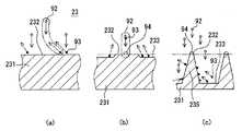
撥水層23は、その外壁面27に、図4に示すような微細な凹凸を有する凹凸構造を設けている。この凹凸構造は、凹凸のうち、凸部235が円錐状を呈する柱状突起であって、円錐状を呈する柱状突起が基材231の底部より燃焼室106側(図1中の下方向、図4中では上方向)に延びている。 The
図5は、撥水層23の凹凸構造を模式的に示している。凹凸構造には、基材231の表面に、燃料の液滴の大きさより十分に小さい微細な凹凸が形成されている。なお、この微細な凹凸を有する撥水層23の形成方法については、後述する。 FIG. 5 schematically shows the uneven structure of the
図5に示されるように、燃料の液滴は、凸部235と、凸部235間に形成された空気層とに接し、凸部235の丁部表面及び空気層の表面によって支持されている。ここで、液滴が接触する表面に関し、凸部235の丁部表面が占める割合をS1とし、空気層表面が占める割合をS2とする。また、凸部235、即ち基材231における金属材料の真の接触角をθ1とし、空気層の真の接触角をθ2とする。 As shown in FIG. 5, the fuel droplet is in contact with the
このとき、液滴に対する撥水層23の接触角θは、以下の式で表される。 At this time, the contact angle θ of the
cosθ=S1×cosθ1+S2×cosθ2
空気層の場合はθ2=180°であるので、凸部235の丁部表面割合S1を小さく設定することにより、撥水層23の接触角θを大きくし得るのである。cos θ = S1 × cos θ1 + S2 × cos θ2
In the case of the air layer, θ2 = 180 °. Therefore, the contact angle θ of the water-
凸部235は、その丁部表面に、プラズマイオン92と基材231の金属の原子93で形成される合金94が形成されている。この合金94の大きさにより、微細な丁部表面の大きさが決定されている。なお、本実施形態では、プラズマイオン92を、Gaイオンとし、基材231、撥水層23の原子93を、Mgとした。 The
このような凸部235を有する凹凸構造では、基材231の金属材料の真の接触角が90°以下のものであっても、撥水層23の接触角θを90°より大きくし得るので、基材231の金属材料が撥水性、親水性のいずれであるかにかかわらず、撥水層23の接触角θを大きくし、撥水層23に優れた撥水性を付与することができる。 In such a concavo-convex structure having the
こうした撥水層23は、凸部235を含む微細な凹凸により撥水性が付与されるものであるので、基材231の金属、及びその合金94で構成されている。言い換えると、撥水層23は、従来技術のFAS被膜のような有機物ではなく、基材231の金属を含む無機物で構成されるので、FAS被膜などの有機物で構成される撥水層に比べて、耐熱性の向上が図れる。 Such a
以上、燃料噴射弁10の特徴的構成について説明した。以下、撥水層23を有する噴孔プレート20の形成方法を、図2〜図3に基づいて説明する。 The characteristic configuration of the
(撥水層23を有する噴孔プレート20の形成方法)
噴孔プレート20の形成工程は、本体部形成工程、基材蒸着工程、及びプラズマエッチング工程を備えている。
(本体部形成工程)
本体部形成工程は、本体部22を、ステンレス鋼(SUS)製で形成する。本体部22には、プレス加工などにより噴孔21を形成する。噴孔21の噴孔内壁面21cに撥水層23を形成する場合には、エンジンの要求性能から決まる噴孔21の最適な内径に対し、撥水層23の厚さを考慮し、最適内径より大きく形成する。(Method for forming
The formation process of the
(Main body forming process)
In the main body portion forming step, the
以下の説明では、説明の簡略化のため、撥水層23を噴孔プレート20の外壁面27に形成する場合で説明する。
(基材蒸着工程)
噴孔プレート20の本体部22の表面に、マグネシウム(Mg)からなる基材231を被着する。基材231の本体部22への被着はメッキ処理またはスパッタなどの蒸着処理を用い、撥水層23のもととなる基材231を外壁面27に被膜する。なお、このような噴孔プレート20は、その外壁面27に基材231を被覆する構成でもあり、請求範囲に記載の被覆部材に相当する。
(プラズマエッチング工程)
プラズマエッチング工程では、図2に示す加工装置91により、プラズマイオン92を、噴孔プレート20の基材231の金属表面232に照射する。加工装置91により照射されるプラズマイオン92は、ガリウム(Ga)イオンを照射する。加工装置91は、噴孔プレート20及び図示しない支持台を収容し、真空にする真空装置を有し、アルゴン(Ar)または窒素(N)などのガス雰囲気下で、プラズマを発生させ、プラズマイオン92に運動エネルギーを付与する。In the following description, a case where the
(Base material deposition process)
A
(Plasma etching process)
In the plasma etching process,
加工装置91がプラズマイオン92に付与する運動エネルギーは、プラズマイオン92を基材231に付着させる皮膜形成のためのエネルギーより大きく、プラズマイオン92を基材231にイオン注入するエネルギーより小さい運動エネルギーに調整されている。 The kinetic energy imparted to the
加工装置91から基材231へ照射されるプラズマイオン92は、図3(a)〜図3(c)の撥水層23の形成過程に示されるように、基材231をエッチングする運動エネルギーを有している。 As shown in the formation process of the
図3(a)のエッチング初期過程に示すように、加工装置91から照射されるプラズマイオン92は、基材231の金属表面232に高速で接近し、金属表面232の原子93に衝突し、その原子93を弾き飛ばす。プラズマイオン92は原子93を弾き飛ばすと共に、自らも弾かれて金属表面232から遠ざかる。原子93が弾き飛ばされた部位は、金属表面232がエッチングされる。 As shown in the initial etching process of FIG. 3A, the
ここで、図3(a)及び図3(b)の二点鎖線枠内に示すように、プラズマイオン92により弾き飛ばされた原子93の一部に、新たに照射され、金属表面232に高速で接近するプラズマイオン92が衝突する場合がある。このとき、基材231の結晶内の原子93にプラズマイオン92が衝突する場合と異なり、衝突によりエネルギーが高められた原子93とプラズマイオン92の衝突により合金94の粒子が形成される。 Here, as shown in the two-dot chain line frame in FIGS. 3A and 3B, a part of the
衝突により形成された合金94の粒子の運動エネルギーは、プラズマイオン92の運動エネルギーより小さくなる。合金94粒子の運動エネルギーは、原子93を弾き飛ばすエネルギーはなく、基材231の金属表面232に到達しても、金属表面232に合金94の粒子が付着して固定される。 The kinetic energy of the particles of the
基材231の金属表面232に被着した合金94は、基材231の結晶内の原子93に比べてプラズマイオン92によりエッチングされににくくなる。言い換えると、図3(b)及び図3(c)に示されるように、金属表面232のうち、合金94形成がなされていない表面部分が、プラズマイオン92の金属表面232への衝突により、エッチングが促進される。合金94形成がなされていない表面部分は、合金94形成がなされた表面部分より深くエッチングされ、凹部233が形成されることになる。 The
図3(b)及び図3(c)の間、凹部233において、プラズマイオン92により弾き飛ばされた原子93の一部は、凸部235の側壁面に再付着する場合がある。弾き飛ばされた原子93が凸部235の側壁面に再付着する確率は、凹部233の底部側ほど高くなる。 Between FIG. 3B and FIG. 3C, in the
そのように合金94形成がなされた表面部分がエッチングされないことにより、微細な凹凸の凸部235を確実に形成することができる。これにより特徴構成で説明したように、微細な凹凸のうちの凸部235間には空気層が形成されるので、基材231の表面に微細な凹凸を形成することで、優れた撥水性を有する撥水層23を形成し得るのである。 By not etching the surface portion on which the
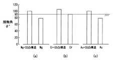
ここで、発明者らは本実施形態による撥水層23の接触角θを測定した。図6(a)はMgの金属材料製の基材231に凹凸構造を形成した場合(図中の左の棒グラフ)と、凹凸構造を形成しない場合(図中の右の棒グラフ)を示している。Mgの真の接触角θ1が約80°程度であっても、本実施形態による凸部235を有する凹凸構造を備えた撥水層23の接触角θは、90°をはるかに超え、約100°に到達することができる。 Here, the inventors measured the contact angle θ of the
微細な凹凸のうちの凸部235は、円錐状を呈する柱状突起に形成されているので、デポジットまたは残留燃料が凹凸構造に付着する場合、凸部235間の空気層と凸部235とへの付着割合に関し、空気層に対し凸部235の付着割合を効果的に小さくすることができる。したがって、そのような撥水層23は、撥水性を高めることができ、ひいてはデポジット付着抑制の効果を高めることができる。 Since the
なお、基材231の金属材料がマグネシウム(Mg)の場合には、上記プラズマエッチング工程が終了した後に、噴孔プレート20の基材231を、酸化雰囲気中で加熱酸化する加熱酸化工程を備えていることが好ましい。これにより、噴孔プレート20における撥水層23は、耐酸化性及び耐熱性に係わる耐久性向上が図れるとともに、噴孔へのデポジット付着抑制を保証し得るのである。 In addition, when the metal material of the
以上説明した本実施形では、噴孔プレート20の本体部22に対し、本体部22以外の一部を金属の基材231で形成する構成としている。それ故に、噴孔プレート20のうち、撥水層23が必要な部位のみを、金属の基材231で構成することができる。したがって、金属の基材231からなる撥水層23を備える噴孔プレート20は、当該金属基材231の金属の材料使用量を抑えることができる。 In the present embodiment described above, a part other than the
また、噴孔プレート20の本体部22は、ステンレス鋼で形成されている。これに限らず、噴孔プレート20の本体部22は、ステンレス鋼などの鉄を含む鉄系基材で形成するもので構成することができる。 Moreover, the main-
また、以上説明した本実施形では、燃料を噴射する噴孔21を有する燃料噴射弁10であって、少なくとも噴孔21の噴孔内壁面21c、及び噴孔21の開口部周辺に、撥水層23を備える燃料噴射弁10であることが好ましい。そのような燃料噴射弁10においては、噴孔21の噴孔内壁面21c、及び噴孔21の出口部21aなどの開口部周辺は、デポジットの付着抑制機能を長期にわたって維持し得るのである。 Further, in the present embodiment described above, the
(他の実施形態)
以上、本発明の一実施形態について説明したが、本発明は本実施形態に限定して解釈されるものではなく、その要旨を逸脱しない範囲内において種々の実施形態に適用することができる。(Other embodiments)
As mentioned above, although one Embodiment of this invention was described, this invention is limited to this embodiment and is not interpreted and can be applied to various embodiment within the range which does not deviate from the summary.
(1)以上説明した本実施形態では、プラズマイオン92を、Gaイオンとし、基材231、撥水層23の原子93を、Mgとした。プラズマイオン92としては、Gaイオンに限らず、基材231を構成する金属の原子と合金を形成するプラズマイオンであれば、いずれであってもよい。 (1) In the present embodiment described above, the
(2)上記原子93を、Mgに代えて、クロム(Cr)としてもよい。この場合、Crの真の接触角θ1は約92°程度である。これに対し、凸部235を有する凹凸構造を備えた撥水層23の接触角θは、約105°に到達し、撥水層23の撥水性を効果的に高めることができる。 (2) The
(3)上記基材231の金属材料がクロム(Cr)の場合には、プラズマエッチング工程が終了した後に、加熱酸化工程を備える必要がないので、噴孔プレート20の撥水層23を形成する工程の簡素化が図れる。 (3) When the metal material of the
(4)また、上記基材231の金属材料を、金(Au)とする構成であってもよい。この場合、Auの真の接触角θ1が約80°程度であるものの、凸部235を有する凹凸構造を備えた撥水層23の接触角θを、約100°に高めることができる。 (4) Further, the metal material of the
(5)以上説明した本実施形態において、基材231の金属材料がMgの場合には、プラズマエッチング工程が終了した後に、加熱酸化工程を備えるようにした。基材231の金属材料としては、Mgに限らず、アルミニウム(Al)、銀(Ag)、亜鉛(Zn)、ニッケル(Ni)、及び銅(Cu)からなる金属材料群から選ばれた少なくとも一種の金属材料であればよい。これによると、プラズマイオンとの衝突により合金が形成される金属としては、Al、Ag、Zn、Ni、Cu、及びMgからなる金属材料群のうちの少なくとも一種の金属材料を用いることができる。 (5) In the present embodiment described above, when the metal material of the
また、上記Al、Ag、Zn、Ni、Cu、及びMgは、耐酸化性が比較的低い金属である。そのため、プラズマエッチング工程が終了した後に、加熱酸化工程を備える構成とすることにより、耐酸化性及び耐熱性に係わる耐久性の向上と、噴孔21へのデポジット付着抑制を保証することとを両立させることができる。 Further, Al, Ag, Zn, Ni, Cu, and Mg are metals with relatively low oxidation resistance. For this reason, after the plasma etching process is completed, a structure including a heating oxidation process achieves both improvement in durability related to oxidation resistance and heat resistance and guaranteeing prevention of deposit adhesion to the
(6)以上説明した本実施形態において、基材231の金属材料を、Au、またはCrとした。ここで、Auに限らず、白金(Pt)、イリジウム(Ir)、パラジウム(Pd)、及びロジウム(Rh)、などの貴金属からなる金属材料群のうちの少なくとも一種の金属材料を用いることができる。 (6) In the present embodiment described above, the metal material of the
また、Crに限らず、チタン(Ti)などの耐酸化性が比較的優れる金属からなる金属材料群のうちの少なくとも一種の金属材料を用いることができる。 Moreover, not only Cr but at least 1 type of metal material in the metal material group which consists of metals with comparatively excellent oxidation resistance, such as titanium (Ti), can be used.
また、タングステン(W)、モリブデン(Mo)、タンタル(Ta)、ニオブ(Nb)、及びレニウム(Re)などの融点が比較的高い金属からなる金属材料群のうちの少なくとも一種の金属材料を用いることができる。 Further, at least one metal material of a metal material group made of a metal having a relatively high melting point such as tungsten (W), molybdenum (Mo), tantalum (Ta), niobium (Nb), and rhenium (Re) is used. be able to.
10 燃料噴射弁
12 弁ボディ
13 円錐面
14 弁座
20 噴孔プレート(噴孔形成部、被覆部材)
20j 中心軸
21 噴孔
21a 出口部(開口部)
21b 入口部
21c 噴孔内壁面
21j 中心軸
22 本体部
23 撥水層
231 基材(金属基材)
232 金属表面(表面)
233 凹部
235 凸部
26 内壁面
27 外壁面
30 弁部材
91 加工装置
92 プラズマイオン
93 原子
94 合金DESCRIPTION OF
20j
232 Metal surface (surface)
233
Claims (8)
Translated fromJapanese前記金属素地にプラズマイオンを照射することにより前記金属素地の表面に凹凸を形成する方法であって、
前記金属素地の金属とプラズマイオンにより合金を形成し、
前記金属素地のうち、前記合金によりエッチングされない部位と、前記合金化されていない金属素地部分がエッチングされる部位とで、凹凸を形成し、
前記凹凸を形成することで撥水層を形成することを特徴とする撥水層の形成方法。In the method of forming the water repellent layer formed on the surface of the metal substrate,
A method of forming irregularities on the surface of the metal substrate by irradiating the metal substrate with plasma ions,
Forming an alloy with the metal of the metal substrate and plasma ions;
Of the metal base, a portion that is not etched by the alloy and a portion where the non-alloyed metal base portion is etched form irregularities,
A method for forming a water-repellent layer, comprising forming the water-repellent layer by forming the irregularities.
少なくとも前記噴孔の噴孔内壁面、及び前記噴孔の開口部周辺に、請求項1から請求項7のいずれか一項に記載の撥水層を備えることを特徴とする燃料噴射弁。A fuel injection valve having an injection hole for injecting fuel,
A fuel injection valve comprising the water-repellent layer according to any one of claims 1 to 7 at least around an inner wall surface of the nozzle hole and around an opening of the nozzle hole.
Priority Applications (3)
| Application Number | Priority Date | Filing Date | Title |
|---|---|---|---|
| JP2009052453AJP4811476B2 (en) | 2009-03-05 | 2009-03-05 | Water repellent layer forming method for forming water repellent layer and fuel injection valve having water repellent layer |
| US12/715,751US8794548B2 (en) | 2009-03-05 | 2010-03-02 | Formation method of water repellent layer and injector having water repellent layer |
| DE102010002593ADE102010002593A1 (en) | 2009-03-05 | 2010-03-04 | Formation method for water-repellent layer and injector with water-repellent layer |
Applications Claiming Priority (1)
| Application Number | Priority Date | Filing Date | Title |
|---|---|---|---|
| JP2009052453AJP4811476B2 (en) | 2009-03-05 | 2009-03-05 | Water repellent layer forming method for forming water repellent layer and fuel injection valve having water repellent layer |
Publications (2)
| Publication Number | Publication Date |
|---|---|
| JP2010202955Atrue JP2010202955A (en) | 2010-09-16 |
| JP4811476B2 JP4811476B2 (en) | 2011-11-09 |
Family
ID=42677353
Family Applications (1)
| Application Number | Title | Priority Date | Filing Date |
|---|---|---|---|
| JP2009052453AExpired - Fee RelatedJP4811476B2 (en) | 2009-03-05 | 2009-03-05 | Water repellent layer forming method for forming water repellent layer and fuel injection valve having water repellent layer |
Country Status (3)
| Country | Link |
|---|---|
| US (1) | US8794548B2 (en) |
| JP (1) | JP4811476B2 (en) |
| DE (1) | DE102010002593A1 (en) |
Cited By (4)
| Publication number | Priority date | Publication date | Assignee | Title |
|---|---|---|---|---|
| KR101258465B1 (en) | 2013-02-18 | 2013-04-26 | 한국기계연구원 | A surface structure of metal having an Superhydrophobic/Superhydrophilic property coatings |
| KR101311754B1 (en) | 2011-04-08 | 2013-09-26 | 한국기계연구원 | Method for fabricating of surface structure of metal having an Superhydrophobic/Superhydrophilic property coatings |
| KR101506714B1 (en) | 2013-03-22 | 2015-04-07 | 리엔리하이테크(주) | Manufacturing method for super-hydrophobic surface with self cleaning capability |
| WO2018154892A1 (en)* | 2017-02-24 | 2018-08-30 | 株式会社日立製作所 | Fuel injection device |
Families Citing this family (11)
| Publication number | Priority date | Publication date | Assignee | Title |
|---|---|---|---|---|
| JP2011125914A (en)* | 2009-12-18 | 2011-06-30 | Denso Corp | Method for forming periodic structure and device for injecting fuel having the periodic structure |
| DE102011086958A1 (en)* | 2011-11-23 | 2013-05-23 | Robert Bosch Gmbh | Component for a fuel injection system with a surface structure and method of manufacturing the component |
| US9546633B2 (en) | 2012-03-30 | 2017-01-17 | Electro-Motive Diesel, Inc. | Nozzle for skewed fuel injection |
| DE102012206913A1 (en)* | 2012-04-26 | 2013-10-31 | Robert Bosch Gmbh | Fuel injection device and method of making such a device |
| DE102012214522B3 (en)* | 2012-08-15 | 2014-03-27 | Ford Global Technologies, Llc | Injector |
| EP2811148B1 (en) | 2013-06-04 | 2016-03-23 | Continental Automotive GmbH | Fluid injector for a combustion engine |
| EP2824313B1 (en)* | 2013-07-10 | 2017-09-06 | Continental Automotive GmbH | Fuel injection valve for a combustion engine |
| US9845779B2 (en) | 2014-06-26 | 2017-12-19 | Continental Automotive Systems, Inc. | Coated high pressure gasoline injector seat to reduce particle emissions |
| JP2019100208A (en)* | 2017-11-29 | 2019-06-24 | 株式会社デンソー | Fuel injection valve |
| DE102018217595A1 (en)* | 2018-10-15 | 2020-04-16 | Continental Automotive Gmbh | Fuel injector and method for producing a nozzle body for a fuel injector |
| DE102018217598A1 (en)* | 2018-10-15 | 2020-04-16 | Continental Automotive Gmbh | Fuel injector and method for producing a nozzle body for a fuel injector |
Citations (3)
| Publication number | Priority date | Publication date | Assignee | Title |
|---|---|---|---|---|
| JP2006220072A (en)* | 2005-02-10 | 2006-08-24 | Denso Corp | Fuel injection valve |
| JP2009030489A (en)* | 2007-07-25 | 2009-02-12 | Toyota Motor Corp | Fuel injection valve |
| JP2009034630A (en)* | 2007-08-03 | 2009-02-19 | Oji Paper Co Ltd | A method for producing a non-planar single particle film, a method for producing a fine structure using the single particle film etching mask, and a fine structure obtained by the production method. |
Family Cites Families (15)
| Publication number | Priority date | Publication date | Assignee | Title |
|---|---|---|---|---|
| US4742964A (en)* | 1985-10-30 | 1988-05-10 | Aisan Kogyo Kabushiki Kaisha | Electromagnetic fuel injector |
| DE3611492A1 (en)* | 1986-04-05 | 1987-10-22 | Leybold Heraeus Gmbh & Co Kg | METHOD AND DEVICE FOR COATING TOOLS FOR CUTTING AND FORMING TECHNOLOGY WITH PLASTIC LAYERS |
| JPH0524887A (en) | 1991-07-15 | 1993-02-02 | Nissan Motor Co Ltd | Water repellent glass |
| JP3060876B2 (en)* | 1995-02-15 | 2000-07-10 | 日新電機株式会社 | Metal ion implanter |
| JP3145322B2 (en) | 1996-11-29 | 2001-03-12 | トヨタ自動車株式会社 | Fuel injection valve for in-cylinder internal combustion engine |
| US20020189931A1 (en)* | 1997-12-04 | 2002-12-19 | Korea Institute Of Science And Technology | Plasma polymerization enhancement of surface of metal for use in refrigerating and air conditioning |
| JP2001199069A (en) | 2000-01-21 | 2001-07-24 | Casio Comput Co Ltd | Method of manufacturing inkjet printer head and inkjet printing apparatus |
| US7026009B2 (en)* | 2002-03-27 | 2006-04-11 | Applied Materials, Inc. | Evaluation of chamber components having textured coatings |
| JP2005089771A (en) | 2003-09-12 | 2005-04-07 | Casio Comput Co Ltd | Water-repellent structure and manufacturing method thereof |
| JP2005254637A (en) | 2004-03-12 | 2005-09-22 | Casio Comput Co Ltd | Water-repellent structure and manufacturing method thereof |
| JP2006161731A (en) | 2004-12-08 | 2006-06-22 | Denso Corp | Fuel injection device |
| TWI322833B (en)* | 2005-12-27 | 2010-04-01 | Ind Tech Res Inst | Water-repellent structure and method for making the same |
| US20080132060A1 (en)* | 2006-11-30 | 2008-06-05 | Macronix International Co., Ltd. | Contact barrier layer deposition process |
| US7383792B1 (en)* | 2006-12-27 | 2008-06-10 | Sharpe Thomas H | Hydrogen gas injector plug |
| JP4492696B2 (en)* | 2007-12-25 | 2010-06-30 | 株式会社デンソー | Fuel injection valve |
- 2009
- 2009-03-05JPJP2009052453Apatent/JP4811476B2/ennot_activeExpired - Fee Related
- 2010
- 2010-03-02USUS12/715,751patent/US8794548B2/enactiveActive
- 2010-03-04DEDE102010002593Apatent/DE102010002593A1/ennot_activeWithdrawn
Patent Citations (3)
| Publication number | Priority date | Publication date | Assignee | Title |
|---|---|---|---|---|
| JP2006220072A (en)* | 2005-02-10 | 2006-08-24 | Denso Corp | Fuel injection valve |
| JP2009030489A (en)* | 2007-07-25 | 2009-02-12 | Toyota Motor Corp | Fuel injection valve |
| JP2009034630A (en)* | 2007-08-03 | 2009-02-19 | Oji Paper Co Ltd | A method for producing a non-planar single particle film, a method for producing a fine structure using the single particle film etching mask, and a fine structure obtained by the production method. |
Cited By (4)
| Publication number | Priority date | Publication date | Assignee | Title |
|---|---|---|---|---|
| KR101311754B1 (en) | 2011-04-08 | 2013-09-26 | 한국기계연구원 | Method for fabricating of surface structure of metal having an Superhydrophobic/Superhydrophilic property coatings |
| KR101258465B1 (en) | 2013-02-18 | 2013-04-26 | 한국기계연구원 | A surface structure of metal having an Superhydrophobic/Superhydrophilic property coatings |
| KR101506714B1 (en) | 2013-03-22 | 2015-04-07 | 리엔리하이테크(주) | Manufacturing method for super-hydrophobic surface with self cleaning capability |
| WO2018154892A1 (en)* | 2017-02-24 | 2018-08-30 | 株式会社日立製作所 | Fuel injection device |
Also Published As
| Publication number | Publication date |
|---|---|
| US20100224706A1 (en) | 2010-09-09 |
| US8794548B2 (en) | 2014-08-05 |
| JP4811476B2 (en) | 2011-11-09 |
| DE102010002593A1 (en) | 2010-11-04 |
Similar Documents
| Publication | Publication Date | Title |
|---|---|---|
| JP4811476B2 (en) | Water repellent layer forming method for forming water repellent layer and fuel injection valve having water repellent layer | |
| JP4492696B2 (en) | Fuel injection valve | |
| US6508416B1 (en) | Coated fuel injector valve | |
| JP3742651B2 (en) | Solenoid operated valve | |
| JP4267824B2 (en) | Fuel injector with scale deposition prevention ceramic coating for direct injection | |
| CN102575627B (en) | Electromagnetic fuel injection valve | |
| JP4416023B2 (en) | Fuel injection valve | |
| US20070228193A1 (en) | Fuel injector | |
| US20110147493A1 (en) | Method for forming periodic structure and fuel injection system having the periodic structure | |
| JPH09112392A (en) | Fuel injection nozzle for internal combustion engine and manufacture thereof | |
| WO2016063390A1 (en) | Valve device for fuel injection valve | |
| KR20020020754A (en) | Fuel-injection valve | |
| US20080057195A1 (en) | Non-line of sight coating technique | |
| CN1171013C (en) | fuel injection valve | |
| EP2674514B1 (en) | Structure and method for coating a nozzle for a fuel injection valve | |
| CN101446253B (en) | Fuel injector | |
| JP2007247519A (en) | Fuel injection valve and manufacturing method thereof | |
| JP6266428B2 (en) | Fuel injection valve | |
| JP2007510093A (en) | Air-assisted fuel injector with a piece of leg / seat | |
| JP2006220072A (en) | Fuel injection valve | |
| JP2009052521A (en) | Fuel injection nozzle and method for manufacturing the same | |
| JP2008064095A (en) | Fuel injection valve | |
| JP6501500B2 (en) | Fuel injection valve | |
| JP4305858B2 (en) | Fuel injection valve | |
| JP3664106B2 (en) | In-cylinder fuel injection valve |
Legal Events
| Date | Code | Title | Description |
|---|---|---|---|
| A621 | Written request for application examination | Free format text:JAPANESE INTERMEDIATE CODE: A621 Effective date:20100622 | |
| A977 | Report on retrieval | Free format text:JAPANESE INTERMEDIATE CODE: A971007 Effective date:20110512 | |
| A131 | Notification of reasons for refusal | Free format text:JAPANESE INTERMEDIATE CODE: A131 Effective date:20110517 | |
| A521 | Request for written amendment filed | Free format text:JAPANESE INTERMEDIATE CODE: A523 Effective date:20110628 | |
| TRDD | Decision of grant or rejection written | ||
| A01 | Written decision to grant a patent or to grant a registration (utility model) | Free format text:JAPANESE INTERMEDIATE CODE: A01 Effective date:20110726 | |
| A01 | Written decision to grant a patent or to grant a registration (utility model) | Free format text:JAPANESE INTERMEDIATE CODE: A01 | |
| A61 | First payment of annual fees (during grant procedure) | Free format text:JAPANESE INTERMEDIATE CODE: A61 Effective date:20110808 | |
| R151 | Written notification of patent or utility model registration | Ref document number:4811476 Country of ref document:JP Free format text:JAPANESE INTERMEDIATE CODE: R151 | |
| FPAY | Renewal fee payment (event date is renewal date of database) | Free format text:PAYMENT UNTIL: 20140902 Year of fee payment:3 | |
| R250 | Receipt of annual fees | Free format text:JAPANESE INTERMEDIATE CODE: R250 | |
| R250 | Receipt of annual fees | Free format text:JAPANESE INTERMEDIATE CODE: R250 | |
| R250 | Receipt of annual fees | Free format text:JAPANESE INTERMEDIATE CODE: R250 | |
| R250 | Receipt of annual fees | Free format text:JAPANESE INTERMEDIATE CODE: R250 | |
| R250 | Receipt of annual fees | Free format text:JAPANESE INTERMEDIATE CODE: R250 | |
| R250 | Receipt of annual fees | Free format text:JAPANESE INTERMEDIATE CODE: R250 | |
| R250 | Receipt of annual fees | Free format text:JAPANESE INTERMEDIATE CODE: R250 | |
| R250 | Receipt of annual fees | Free format text:JAPANESE INTERMEDIATE CODE: R250 | |
| LAPS | Cancellation because of no payment of annual fees |