JP2010202269A - Reaction card manufacturing device - Google Patents
Reaction card manufacturing deviceDownload PDFInfo
- Publication number
- JP2010202269A JP2010202269AJP2009052539AJP2009052539AJP2010202269AJP 2010202269 AJP2010202269 AJP 2010202269AJP 2009052539 AJP2009052539 AJP 2009052539AJP 2009052539 AJP2009052539 AJP 2009052539AJP 2010202269 AJP2010202269 AJP 2010202269A
- Authority
- JP
- Japan
- Prior art keywords
- carrier
- reaction
- card
- container
- dispensing
- Prior art date
- Legal status (The legal status is an assumption and is not a legal conclusion. Google has not performed a legal analysis and makes no representation as to the accuracy of the status listed.)
- Withdrawn
Links
- 238000004519manufacturing processMethods0.000titleclaimsabstractdescription40
- 238000003756stirringMethods0.000claimsabstractdescription22
- 238000003860storageMethods0.000claimsdescription24
- 238000012856packingMethods0.000claimsdescription12
- 238000007789sealingMethods0.000claimsdescription12
- 230000006837decompressionEffects0.000claimsdescription7
- 238000000605extractionMethods0.000claimsdescription3
- 238000012423maintenanceMethods0.000claimsdescription3
- 230000009467reductionEffects0.000claimsdescription3
- 238000013019agitationMethods0.000claims1
- 238000004458analytical methodMethods0.000abstractdescription14
- 230000007246mechanismEffects0.000abstractdescription11
- 239000000969carrierSubstances0.000abstract1
- 239000007788liquidSubstances0.000description15
- 238000010586diagramMethods0.000description11
- 238000000034methodMethods0.000description9
- 230000008569processEffects0.000description8
- 239000003153chemical reaction reagentSubstances0.000description7
- 230000004520agglutinationEffects0.000description5
- 238000012545processingMethods0.000description4
- 230000001900immune effectEffects0.000description3
- 230000002776aggregationEffects0.000description2
- 238000004220aggregationMethods0.000description2
- 239000011324beadSubstances0.000description2
- 238000007872degassingMethods0.000description2
- 238000010438heat treatmentMethods0.000description2
- 239000000203mixtureSubstances0.000description2
- 239000000427antigenSubstances0.000description1
- 102000036639antigensHuman genes0.000description1
- 108091007433antigensProteins0.000description1
- 230000008859changeEffects0.000description1
- 238000004891communicationMethods0.000description1
- 230000000694effectsEffects0.000description1
- 239000011521glassSubstances0.000description1
- 238000003384imaging methodMethods0.000description1
- 238000011534incubationMethods0.000description1
- 239000002184metalSubstances0.000description1
- 210000002381plasmaAnatomy0.000description1
- 239000011347resinSubstances0.000description1
- 229920005989resinPolymers0.000description1
- 210000002966serumAnatomy0.000description1
- 239000000126substanceSubstances0.000description1
- 238000012360testing methodMethods0.000description1
- 238000012546transferMethods0.000description1
- 230000000007visual effectEffects0.000description1
Images


Classifications
- B—PERFORMING OPERATIONS; TRANSPORTING
- B01—PHYSICAL OR CHEMICAL PROCESSES OR APPARATUS IN GENERAL
- B01L—CHEMICAL OR PHYSICAL LABORATORY APPARATUS FOR GENERAL USE
- B01L3/00—Containers or dishes for laboratory use, e.g. laboratory glassware; Droppers
- B01L3/52—Containers specially adapted for storing or dispensing a reagent
- B—PERFORMING OPERATIONS; TRANSPORTING
- B01—PHYSICAL OR CHEMICAL PROCESSES OR APPARATUS IN GENERAL
- B01F—MIXING, e.g. DISSOLVING, EMULSIFYING OR DISPERSING
- B01F29/00—Mixers with rotating receptacles
- B01F29/30—Mixing the contents of individual packages or containers, e.g. by rotating tins or bottles
- B01F29/31—Mixing the contents of individual packages or containers, e.g. by rotating tins or bottles the containers being supported by driving means, e.g. by rotating rollers
- B—PERFORMING OPERATIONS; TRANSPORTING
- B01—PHYSICAL OR CHEMICAL PROCESSES OR APPARATUS IN GENERAL
- B01J—CHEMICAL OR PHYSICAL PROCESSES, e.g. CATALYSIS OR COLLOID CHEMISTRY; THEIR RELEVANT APPARATUS
- B01J19/00—Chemical, physical or physico-chemical processes in general; Their relevant apparatus
- B01J19/0006—Controlling or regulating processes
- B01J19/004—Multifunctional apparatus for automatic manufacturing of various chemical products
- B—PERFORMING OPERATIONS; TRANSPORTING
- B01—PHYSICAL OR CHEMICAL PROCESSES OR APPARATUS IN GENERAL
- B01J—CHEMICAL OR PHYSICAL PROCESSES, e.g. CATALYSIS OR COLLOID CHEMISTRY; THEIR RELEVANT APPARATUS
- B01J19/00—Chemical, physical or physico-chemical processes in general; Their relevant apparatus
- B01J19/28—Moving reactors, e.g. rotary drums
- B—PERFORMING OPERATIONS; TRANSPORTING
- B01—PHYSICAL OR CHEMICAL PROCESSES OR APPARATUS IN GENERAL
- B01J—CHEMICAL OR PHYSICAL PROCESSES, e.g. CATALYSIS OR COLLOID CHEMISTRY; THEIR RELEVANT APPARATUS
- B01J4/00—Feed or outlet devices; Feed or outlet control devices
- B01J4/02—Feed or outlet devices; Feed or outlet control devices for feeding measured, i.e. prescribed quantities of reagents
- B—PERFORMING OPERATIONS; TRANSPORTING
- B01—PHYSICAL OR CHEMICAL PROCESSES OR APPARATUS IN GENERAL
- B01J—CHEMICAL OR PHYSICAL PROCESSES, e.g. CATALYSIS OR COLLOID CHEMISTRY; THEIR RELEVANT APPARATUS
- B01J2219/00—Chemical, physical or physico-chemical processes in general; Their relevant apparatus
- B01J2219/00002—Chemical plants
- B01J2219/00027—Process aspects
- B01J2219/00038—Processes in parallel
- B—PERFORMING OPERATIONS; TRANSPORTING
- B01—PHYSICAL OR CHEMICAL PROCESSES OR APPARATUS IN GENERAL
- B01L—CHEMICAL OR PHYSICAL LABORATORY APPARATUS FOR GENERAL USE
- B01L2200/00—Solutions for specific problems relating to chemical or physical laboratory apparatus
- B01L2200/06—Fluid handling related problems
- B01L2200/0642—Filling fluids into wells by specific techniques
- B—PERFORMING OPERATIONS; TRANSPORTING
- B01—PHYSICAL OR CHEMICAL PROCESSES OR APPARATUS IN GENERAL
- B01L—CHEMICAL OR PHYSICAL LABORATORY APPARATUS FOR GENERAL USE
- B01L2200/00—Solutions for specific problems relating to chemical or physical laboratory apparatus
- B01L2200/06—Fluid handling related problems
- B01L2200/0684—Venting, avoiding backpressure, avoid gas bubbles
- B—PERFORMING OPERATIONS; TRANSPORTING
- B01—PHYSICAL OR CHEMICAL PROCESSES OR APPARATUS IN GENERAL
- B01L—CHEMICAL OR PHYSICAL LABORATORY APPARATUS FOR GENERAL USE
- B01L2200/00—Solutions for specific problems relating to chemical or physical laboratory apparatus
- B01L2200/12—Specific details about manufacturing devices
- B—PERFORMING OPERATIONS; TRANSPORTING
- B01—PHYSICAL OR CHEMICAL PROCESSES OR APPARATUS IN GENERAL
- B01L—CHEMICAL OR PHYSICAL LABORATORY APPARATUS FOR GENERAL USE
- B01L3/00—Containers or dishes for laboratory use, e.g. laboratory glassware; Droppers
- B01L3/50—Containers for the purpose of retaining a material to be analysed, e.g. test tubes
- B01L3/502—Containers for the purpose of retaining a material to be analysed, e.g. test tubes with fluid transport, e.g. in multi-compartment structures
- B01L3/5021—Test tubes specially adapted for centrifugation purposes
- G—PHYSICS
- G01—MEASURING; TESTING
- G01N—INVESTIGATING OR ANALYSING MATERIALS BY DETERMINING THEIR CHEMICAL OR PHYSICAL PROPERTIES
- G01N35/00—Automatic analysis not limited to methods or materials provided for in any single one of groups G01N1/00 - G01N33/00; Handling materials therefor
- G01N35/02—Automatic analysis not limited to methods or materials provided for in any single one of groups G01N1/00 - G01N33/00; Handling materials therefor using a plurality of sample containers moved by a conveyor system past one or more treatment or analysis stations
- G01N35/04—Details of the conveyor system
- G01N2035/0401—Sample carriers, cuvettes or reaction vessels
- G01N2035/0429—Sample carriers adapted for special purposes
- G01N2035/0436—Sample carriers adapted for special purposes with pre-packaged reagents, i.e. test-packs
- G—PHYSICS
- G01—MEASURING; TESTING
- G01N—INVESTIGATING OR ANALYSING MATERIALS BY DETERMINING THEIR CHEMICAL OR PHYSICAL PROPERTIES
- G01N35/00—Automatic analysis not limited to methods or materials provided for in any single one of groups G01N1/00 - G01N33/00; Handling materials therefor
- G01N35/02—Automatic analysis not limited to methods or materials provided for in any single one of groups G01N1/00 - G01N33/00; Handling materials therefor using a plurality of sample containers moved by a conveyor system past one or more treatment or analysis stations
- G01N35/026—Automatic analysis not limited to methods or materials provided for in any single one of groups G01N1/00 - G01N33/00; Handling materials therefor using a plurality of sample containers moved by a conveyor system past one or more treatment or analysis stations having blocks or racks of reaction cells or cuvettes
Landscapes
- Chemical & Material Sciences (AREA)
- Chemical Kinetics & Catalysis (AREA)
- Organic Chemistry (AREA)
- Health & Medical Sciences (AREA)
- Engineering & Computer Science (AREA)
- Manufacturing & Machinery (AREA)
- Medicinal Chemistry (AREA)
- Clinical Laboratory Science (AREA)
- Automatic Analysis And Handling Materials Therefor (AREA)
- Basic Packing Technique (AREA)
- Mixers With Rotating Receptacles And Mixers With Vibration Mechanisms (AREA)
- Feeding, Discharge, Calcimining, Fusing, And Gas-Generation Devices (AREA)
Abstract
Description
Translated fromJapanese本発明は、免疫学的凝集反応を行う複数の反応容器を有する反応カードの製造方法に関するものである。 The present invention relates to a method for producing a reaction card having a plurality of reaction vessels for performing an immunological agglutination reaction.
従来、血漿、血球または血清などの検体を免疫学的に分析する分析方法においては、検査内容に対応した試薬を専用の反応カード内の反応容器で検体と混和して反応させ、必要に応じてインキュベーションを行った後、その反応カードを遠心器で遠心することによって生じる反応像から凝集の有無を確認し、検体と試薬との凝集反応パターンをもとに検体が抗体または抗原に対して陰性であるか陽性であるかを判定する。 Conventionally, in an analysis method for immunologically analyzing a sample such as plasma, blood cells, or serum, a reagent corresponding to the test content is mixed with the sample in a reaction container in a dedicated reaction card and reacted. After incubation, the presence or absence of agglutination is confirmed from the reaction image generated by centrifuging the reaction card with a centrifuge. The sample is negative for antibody or antigen based on the agglutination pattern of the sample and reagent. Determine if it is positive or negative.
ところで、上述した反応カードの反応容器は、検体と試薬とを混合させて免疫学的凝集反応を行なわせる反応部と、反応部下部に連結され、免疫学的凝集反応を行なわせた反応液を、反応液の大きさに応じて移動度を変化させる担体を収容した分析部とを有している。分析部に収容する担体において、担体内に気泡が混入すると、気泡を凝集と誤判定する、または反応液の担体内へ移動度が変化する等、分析の結果に影響を及ぼすという問題があり、反応容器内に収容された担体内に気泡が混入していないことが望まれている。この問題に対し、気泡の混入を防ぐ方法として、混合物を収容した容器内を陰圧に設定して、脱気を行う製造方法が開示されている(例えば、特許文献1参照)。 By the way, the reaction container of the above-mentioned reaction card includes a reaction part that mixes a sample and a reagent to perform an immunological agglutination reaction, and a reaction solution that is connected to the lower part of the reaction part and that performs the immunological agglutination reaction. And an analysis unit containing a carrier whose mobility is changed according to the size of the reaction solution. In the carrier housed in the analysis unit, if bubbles are mixed in the carrier, there is a problem that the analysis results are affected, such as misjudging the bubbles as aggregation or the mobility of the reaction solution changes into the carrier, It is desired that bubbles are not mixed in the carrier accommodated in the reaction vessel. In order to prevent this problem, a manufacturing method is disclosed in which degassing is performed by setting the inside of the container containing the mixture to a negative pressure as a method for preventing the mixture of bubbles (for example, see Patent Document 1).
しかしながら、特許文献1に示す製造方法では、脱気処理を行いながら分注処理を行なう機構がないため、数時間を要する担体の分注においては、分注時に担体内に気泡が混入するおそれがあった。 However, in the manufacturing method shown in Patent Document 1, there is no mechanism for performing a dispensing process while performing a deaeration process. Therefore, in the dispensing of a carrier that requires several hours, there is a possibility that bubbles are mixed in the carrier at the time of dispensing. there were.
本発明は、上記に鑑みてなされたものであって、分析精度を向上させる反応カードの製造を行う反応カード製造装置を提供することを目的とする。 This invention is made | formed in view of the above, Comprising: It aims at providing the reaction card manufacturing apparatus which manufactures the reaction card which improves analysis accuracy.
上述した課題を解決し、目的を達成するために、本発明は、担体を収容する反応容器を少なくとも1つ以上有する反応カードを製造する反応カード製造装置において、前記反応容器に収容される前記担体を保持する担体保持容器を回転させ、該担体保持容器に収容された前記担体の攪拌を行なう攪拌手段と、前記担体保持容器の内部空間を減圧する減圧手段と、前記攪拌手段による攪拌と前記減圧手段よる減圧とを行ないつつ、前記担体を前記反応容器に分注する分注手段と、を備えたことを特徴とする。 In order to solve the above-described problems and achieve the object, the present invention provides a reaction card manufacturing apparatus for manufacturing a reaction card having at least one reaction container for storing a carrier, and the carrier accommodated in the reaction container. A carrier holding container for holding the carrier, stirring means for stirring the carrier housed in the carrier holding container, pressure reducing means for reducing the internal space of the carrier holding container, stirring by the stirring means and the pressure reduction Dispensing means for dispensing the carrier into the reaction vessel while performing pressure reduction by the means.
また、本発明にかかる反応カード製造装置は、上記の発明において、前記担体保持容器は、密閉可能な筒状であって、上端開口部に開閉可能な蓋と、底部に設けられた管状の、前記担体を取り出す取出管と、を有し、前記攪拌手段は、前記担体保持容器を収納し、底部に前記取出管を貫通させる孔を有する収納部と、前記収納部の側面に設けられた歯合部と、前記歯合部と歯合するギアを有する駆動部と、を備え、前記駆動部の駆動によるギアの駆動によって、該ギアが歯合している前記歯合部に動力を伝達させることで前記収納部を回転させ、前記担体保持容器に収容された前記担体を攪拌することを特徴とする。 Further, in the reaction card manufacturing apparatus according to the present invention, in the above invention, the carrier holding container has a cylindrical shape that can be sealed, a lid that can be opened and closed at an upper end opening, and a tubular shape provided at the bottom. A take-out pipe for taking out the carrier, and the stirring means contains the carrier holding container and has a housing part having a hole through which the take-out pipe penetrates, and a tooth provided on a side surface of the storage part And a drive unit having a gear meshing with the meshing part, and driving the gear by driving the drive part transmits power to the meshing part meshed with the gear. Thus, the storage portion is rotated to stir the carrier accommodated in the carrier holding container.
また、本発明にかかる反応カード製造装置は、上記の発明において、前記担体保持容器は、密閉可能な筒状であって、上端開口部に開閉可能な蓋と、底部に設けられた管状の、前記担体を取り出す取出管と、前記担体保持容器外周に形成された歯合部と、を備え、前記攪拌手段は、前記歯合部に動力を伝達させることで、該担体保持容器に収容された前記担体を攪拌することを特徴とする。 Further, in the reaction card manufacturing apparatus according to the present invention, in the above invention, the carrier holding container has a cylindrical shape that can be sealed, a lid that can be opened and closed at an upper end opening, and a tubular shape provided at the bottom. An extraction tube for taking out the carrier; and a meshing portion formed on the outer periphery of the carrier holding container; and the stirring means is accommodated in the carrier holding container by transmitting power to the meshing portion. The carrier is stirred.
また、本発明にかかる反応カード製造装置は、上記の発明において、前記減圧手段は、前記蓋に配置された脱気配管を介して前記担体保持容器内の脱気を行なうことを特徴とする。 In the reaction card manufacturing apparatus according to the present invention as set forth in the invention described above, the decompression means performs deaeration in the carrier holding container through a deaeration pipe disposed on the lid.
また、本発明にかかる反応カード製造装置は、上記の発明において、前記分注手段は、前記担体保持容器の前記取出管に接続された分注配管を介して前記反応容器に分注することを特徴とする。 In the reaction card manufacturing apparatus according to the present invention, in the above invention, the dispensing means dispenses the reaction container via the dispensing pipe connected to the take-out pipe of the carrier holding container. Features.
また、本発明にかかる反応カード製造装置は、上記の発明において、前記担体保持容器は、前記反応容器に収容する前記担体の種別に対応して設けられ、前記分注手段は、各担体保持容器に対応して接続された前記分注配管によって各反応容器に前記担体の分注を行なうことを特徴とする。 Further, in the reaction card manufacturing apparatus according to the present invention, in the above invention, the carrier holding container is provided corresponding to a type of the carrier accommodated in the reaction container, and the dispensing means includes each carrier holding container. The carrier is dispensed to each reaction vessel by the dispensing pipe connected corresponding to the above.
また、本発明にかかる反応カード製造装置は、上記の発明において、担体収容前の反応カードを収容し、前記反応カードを供給するカード供給部と、前記分注手段による前記担体の分注が終了した前記反応カードに対して、前記反応容器を封止する封止部材および前記反応カードに関する情報が記載されたシールを貼付する貼付部と、前記貼付部によって前記封止部材および前記シールが貼付された前記反応カードを梱包する梱包部と、前記カード供給部と前記梱包部との間の前記反応カードの搬送を行なうカード搬送手段と、をさらに備えたことを特徴とする。 In the reaction card manufacturing apparatus according to the present invention, in the above invention, the reaction card before receiving the carrier is stored, the card supply unit for supplying the reaction card, and the dispensing of the carrier by the dispensing means is completed. The sealing member and the seal are affixed to the reaction card, the affixing part for affixing the sealing member that seals the reaction container and the information on the reaction card, and the affixing part. The apparatus further comprises a packing section for packing the reaction card, and a card transfer means for transferring the reaction card between the card supply section and the packing section.
本発明によれば、反応容器に収容された担体内に気泡が混入しないようにしたため、分析精度を向上させ、安定した分析を行うことが可能となるという効果を奏する。 According to the present invention, since bubbles are not mixed in the carrier accommodated in the reaction container, the analysis accuracy is improved and stable analysis can be performed.
以下、図面を参照して、この発明の実施の形態である反応カードについて説明する。なお、この実施の形態によりこの発明が限定されるものではない。また、図面の記載において、同一部分には同一の符号を付している。なお、以下の説明で参照する図面は模式的なものであって、同じ物体を異なる図面で示す場合には、寸法や縮尺等が異なる場合もある。 A reaction card according to an embodiment of the present invention will be described below with reference to the drawings. Note that the present invention is not limited to the embodiments. In the description of the drawings, the same parts are denoted by the same reference numerals. Note that the drawings referred to in the following description are schematic, and when the same object is shown in different drawings, dimensions, scales, and the like may be different.
(実施の形態1)
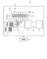
図1は、本発明の実施の形態1にかかる反応カード製造装置1を示す模式図である。図1に示す反応カード製造装置1は、大別して、反応カード3を複数枚収容し、カード搬送ライン10に反応カード3を供給するカード供給部11と、搬送された反応カード3の反応容器31に単体を分注する分注部12と、反応カード3の各反応容器31の開口部を封止する封止部材および識別用のバーコードやロット番号、有効年月日等が印刷されているとともに、検体の情報や反応結果の記載欄を有する情報シートを反応カード3に貼付する貼付部13と、貼付部13から搬送された反応カード3の梱包を行なうカード梱包部14とを有する製造部1aと、製造部1aを含む反応カード製造装置1全体の制御を行なう制御部1bとで構成される。(Embodiment 1)
FIG. 1 is a schematic diagram showing a reaction card manufacturing apparatus 1 according to a first embodiment of the present invention. The reaction card manufacturing apparatus 1 shown in FIG. 1 is roughly divided into a plurality of reaction cards 3, a
カード供給部11は、反応カード3を複数枚整列して収容され、順次カード搬送ライン10に反応カード3を送り込む。反応カード3は、図示しない駆動部によってカード供給部11内を移動して、カード搬送ライン10まで移送される。 The
分注部12は、担体を収容する担体保持容器18を保持する保持部15と、各担体保持容器18底部に接続された分注配管16を連結し、反応カード3の各反応容器31内に担体の分注を行なう分注機構17とを備える。また、各担体保持容器18は、保持部15に列をなして設けられた各容器収納部152に収納され、容器収納部152側面には、歯合部153が形成されている。容器収納部152が、モータの回転駆動によるギア191の回転によって歯合部153に動力が伝達されて回転することで、収納している担体保持容器18を回転させ、担体保持容器18内に収容されている担体の攪拌を行なう。ここで、各担体保持容器18上部には脱気配管181が接続され、ポンプ20による吸気によって担体保持容器18内部の減圧を行なう。 The dispensing unit 12 connects the
貼付部13は、カード搬送ライン10によって搬送される担体を収容した反応カード3の各反応容器31の上部開口部を封止する封止部材を貼付する。また、反応カード3の本体部に、識別用のバーコードやロット番号、有効年月日等が印刷されているとともに、検体の情報や反応結果の記載欄を有する情報シートを貼付する。 The affixing unit 13 affixes a sealing member that seals the upper opening of each
カード梱包部14は、カード搬送ライン10によって搬送される封止部材および情報シートが貼付された反応カード3を、所定数毎にまとめ、梱包する。梱包された反応カード3は、図示しない保管庫へと送られる。 The
以上のように構成された反応カード製造装置1では、制御部1bの制御のもと、列をなして順次搬送される複数の反応カード3に対して、分注部12が反応カード3の各反応容器31に担体を分注した後、貼付部13が反応カード3の各反応容器31を封止する封止部材を貼付して反応容器31を密閉し、カード梱包部14が各反応カード3を梱包することで反応カードの製造が自動的に行なわれる。 In the reaction card manufacturing apparatus 1 configured as described above, the dispensing unit 12 is provided for each of the reaction cards 3 with respect to the plurality of reaction cards 3 that are sequentially conveyed in a row under the control of the control unit 1b. After dispensing the carrier into the
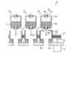
ここで、分注部12について、図2を参照して説明する。図2は、分注部12を模式的に示す模式図である。図2に示す分注部12は、担体保持容器18を収納し、モータ19を有するブロック151で構成される保持部15と、反応カード3が有する反応容器31の数に応じて設けられた分注ノズル172を有する分注機構17と、担体保持容器18底部に連結され、分注機構17と接続された分注配管16とを有する。分注配管16は、電磁弁16a,16bと、シリンジポンプ161とを有し、このシリンジポンプ161によって担体保持容器18内の担体を吸引して、分注ノズル172に送り込み、分注機構17は、所定位置に搬送された反応カード3の各反応容器31に担体を所定量分注する。電磁弁16aは、シリンジポンプ161が各担体保持容器18内の担体を吸引する場合に開放され、シリンジポンプ161が吸引した担体を分注ノズル172から吐出する場合に閉鎖される。また、電磁弁16bは、シリンジポンプ161が各担体保持容器18内の担体を吸引する場合に閉鎖され、シリンジポンプ161が吸引した担体を分注ノズル172から吐出する場合に開放される。電磁弁16a,16bは、図1に示す制御部1bの制御によって切り替えられ、各担体保持容器18内の担体を各反応容器31に分注する。この電磁弁の切り替えによって、担体保持容器18内を減圧しながら反応容器31への分注を行なうことが可能となる。また、各担体保持容器18上部には脱気配管181が接続され、図示しない制御部の制御のもと、ポンプ20による吸気によって担体保持容器18内部の減圧を行なう。 Here, the dispensing unit 12 will be described with reference to FIG. FIG. 2 is a schematic diagram schematically showing the dispensing unit 12. The dispensing unit 12 shown in FIG. 2 accommodates the
図2において、担体保持容器18が容器収納部152に収納され、分注配管16と脱気配管181とが接続されると、図示しない駆動部によってモータ19が駆動し、ギア191が回転する。ギア191の回転によって、隣接して歯合された歯合部153に動力が伝達され、歯合部153が回転し、この回転に従って容器収納部152が回転する。なお、歯合部153を隣接して配置することによって隣り合う容器収納部152を回転させることが可能となる。容器収納部152が回転すると、内部に収納されている担体保持容器18が回転し、担体保持容器18の内部に収容されている担体が回転攪拌され、担体を均一に攪拌することができる。また、各容器収納部152の回転は、隣接するギアまたは容器収納部と逆方向に回転する。ここで、担体保持容器18は、底部に分注配管16を接続し、シリンジポンプ161における図示しない駆動部によるピストン163の駆動によってシリンジ162の内部圧力が変化し、分注配管16を介して担体保持容器18内部の担体を吸引することができる。その後、分注配管16を接続し、分注ノズル172に担体を送り込む接続部171を支持する板状部材173が、図示しない駆動部によって昇降されることで、各分注ノズル172が、各反応容器31内部に挿入されて、反応容器31に担体の分注を行なう。 In FIG. 2, when the
また、図3は、図1,2に示す反応カード3を模式的に示す斜視図である。反応カード3は、カード状をなす本体部30と、本体部の上端平面部に開口を有する反応容器31と、本体部30に貼付され、識別用のバーコードやロット番号、有効年月日等が印刷されているとともに、検体の情報や反応結果の記載欄を有するシール34とを有する。反応容器31は、略円筒形状をなし、検体と試薬とを反応させる反応部32と、反応部32の底部に連通して設けられ、反応の結果に応じた凝集の有無を判定するための反応像を生じさせる担体としてゲル、ガラスビーズまたはプラスチックビーズが充填されて、検体と試薬との抗原抗体反応による反応液を遠心器によって遠心したものを保持する分析部33とを有する。反応カード3は、半透明の樹脂を用いて形成されている。分析部33における凝集像は、目視または撮像によって確認される。また、本体部30の上部平面は、封止部材35によって各反応容器31の上部開口部を封止され、各反応容器31内部の密閉性が保たれている。反応カード3を使用する場合は、封止部材35を剥がすか、若しくは開口部分を穿孔することによって、反応容器31内に検体及び試薬を分注して使用する。 FIG. 3 is a perspective view schematically showing the reaction card 3 shown in FIGS. The reaction card 3 is a card-shaped
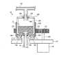
ここで、保持部15について、図4を参照して説明する。図4は、図1,2に示す分注部12の保持部15を模式的に示す模式図である。図4において、ブロック151の一方の端部側下方にはモータ19が設けられ、モータ19は、モータ19上部に接続され、ブロック151を貫通してギア191を支持してモータ19の回転動力をギア191に伝達する棒状部材192を有する。また、ブロック151には、円筒状の孔が形成され、ブロック151の上部平面であって、孔の外周近傍に環状のベアリング154が設けられている。さらに、ベアリング154上部には、内部に空間領域を形成し、空間領域に担体保持容器18を収納する、円筒状の容器収納部152が配置され、容器収納部152外周には歯合部153が形成されている。 Here, the holding |
また、担体保持容器18は、大別して、上部に開口部を有し、担体Cを収容する担体収容部182と、担体収容部182の上部開口部を密閉する蓋183とで構成される。ここで、担体収容部182底部中央部には、送液管185が接続されており、送液管185外周と担体収容部182との間はベアリング184によって接続されている。同様に、蓋183においても、蓋183中央部に排気管186が接続され、排気管186外周は、ベアリング184を介して蓋183と接続されている。なお、送液管185は、担体保持容器18が容器収納部152に収納された場合に、容器収納部152およびブロック151に形成された孔に挿入される。上述した構成が、担体保持容器18に対応して複数設けられ、ギア191と歯合した歯合部153が、モータ19の駆動によるギア191の回転動力を受けて回転することで、隣接する歯合部153に動力を伝達する。歯合部153の回転に従って容器収納部152が回転することによって、担体保持容器18も回転し、担体保持容器18内に収容された担体Cが攪拌される。なお、容器収納部152の回転動力は、ベアリング154によってブロック151に伝達されない。 The
上述した構成によって、モータ19の動力をギア191が担体保持容器18の歯合部153に伝達することによる担体Cの回転攪拌と、排気管186による減圧処理と、送液管185による分注処理とを同時に行なうことで、気泡を除去した担体Cを安定して反応容器に供給することができる。 With the configuration described above, the
つづいて、図5は、担体保持容器18が容器収納部152に収容された場合を示す模式図である。容器収納部152に収納された担体保持容器18には、送液管185に分注配管16が接続され、排気管186に脱気配管181が接続される。送液管185に連結された分注配管16は、容器収納部152およびブロック151に形成された孔を介してブロック151底部から図1,2に示す分注機構17まで延伸される。また、脱気配管181は、図1,2に示すように、一方がポンプ20に連結され、担体保持容器18内部の減圧を行なう。また、ベアリング184によって、担体保持容器18が回転した場合でも送液管185および排気管186は回転しないため、分注配管16および脱気配管181へ回転の動力が伝達されない。 FIG. 5 is a schematic diagram showing a case where the
ここで、図2に示すポンプ20とシリンジポンプ161との各圧力は、ポンプ20の圧力が、シリンジポンプ161の圧力と比して低いことが好ましい。特に、ポンプ20の吸引圧力が−40kPa〜−80kPaであって、シリンジポンプ161の吸引圧力が−100kPa〜−150kPaであることが好ましい。なお、上記範囲内であれば、ポンプ20とシリンジポンプ161との各吸引圧力は、如何なる組み合わせでもよい。また、分注時以外に送液管185による分注配管16または外部への担体Cの流出を防ぐため、送液管185に、圧力変化によって開閉する蓋を設けることが好ましく、分注配管16が接続された場合に開放可能な開閉機構を送液管185の外部側先端に設けてもよい。ここで、開閉機構は、分注配管16が接続されて送液管185が開放された場合であっても、分注配管16の内部圧力によって担体Cの流出を防止し、シリンジポンプ161の駆動によってのみ担体Cが放出されることが好ましい。 Here, each pressure of the
また、攪拌の効率を向上させるために加温する場合は、担体C中の内容物の活性が失活しない温度以下であれば加温してもよい。各容器収納部152に加温機構を設けることで温度調節を行なうことが可能となる。 Moreover, when heating in order to improve the efficiency of stirring, as long as it is below the temperature which the activity of the content in the support | carrier C does not deactivate, you may heat. Temperature adjustment can be performed by providing a heating mechanism in each
上述した実施の形態1にかかる反応カード製造装置は、攪拌処理、減圧処理および分注処理を同時に行なうことで、担体中の気泡を除去して反応容器内に分注することができるため、分析結果の安定した精度の高い分析を行うことが可能となる。 The reaction card manufacturing apparatus according to the first embodiment described above can remove bubbles in the carrier and dispense into the reaction container by simultaneously performing the stirring process, the decompression process, and the dispensing process. It is possible to perform a stable and accurate analysis of the results.
(実施の形態2)
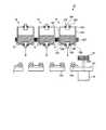
図6,7は、実施の形態2にかかる反応カード製造装置の保持部を示す模式図である。図6,7に示す保持部15において、担体保持容器18は、担体収容部182側面に歯合部187を有し、ベアリング154の上部の形状に対応した凹部188が底部に形成されている。担体保持容器18の凹部188がベアリング154と嵌合することによって、担体保持容器18がブロック151に支持され、歯合部187がギア191若しくは隣接する担体保持容器18の歯合部と歯合して、ギア191を介してモータ19の動力が伝達され、担体保持容器18を回転させることができる。(Embodiment 2)
6 and 7 are schematic diagrams illustrating a holding unit of the reaction card manufacturing apparatus according to the second embodiment. In the holding
また、図7に示すように、担体保持容器18の凹部188がベアリング154と嵌合すると、送液管185に分注配管16を接続し、排気管186に脱気配管181を接続する。実施の形態1と同様に、担体保持容器18の回転動力は、ベアリング154,184によってブロック151、送液管185および排気管186には伝達しない。上述した構成によって、モータ19の動力をギア191が担体保持容器18の歯合部187に伝達することによる担体Cの回転攪拌と、排気管186による減圧処理と、送液管185による分注処理とを同時に行なうことで、気泡を除去した担体Cを安定して反応容器に供給することができる。 Further, as shown in FIG. 7, when the
実施の形態2にかかる反応カード製造装置は、担体保持容器の外周に歯合部を設けたため、簡易な構成で攪拌処理を行うことが可能となる。 Since the reaction card manufacturing apparatus according to the second embodiment is provided with the engagement portion on the outer periphery of the carrier holding container, it is possible to perform the stirring process with a simple configuration.
なお、ブロックにおける容器収納部またはベアリングの配置は、行と列との二次元の配置でもよい。また、分注配管は、金属等の剛性の高い部材を用いてもよく、ゴム等の剛性の低い部材を用いてもよい。 The arrangement of the container storage portion or the bearing in the block may be a two-dimensional arrangement of rows and columns. In addition, the dispensing pipe may be made of a highly rigid member such as metal, or may be made of a less rigid member such as rubber.
上述した実施の形態1,2にかかる反応カード製造装置は、攪拌処理および減圧処理を行いながら分注処理が可能なため、反応容器に分注した担体内に気泡が混入することを防止し、安定して精度の高い分析を行うことができる反応カードを製造することが可能となる。また、均一に攪拌された担体を反応容器に分注することができるため、内容物に試薬等が混合されている場合でも、各反応容器に均一に分注することが可能となる。 The reaction card manufacturing apparatus according to the first and second embodiments described above is capable of dispensing while performing a stirring process and a decompression process, thus preventing bubbles from being mixed into the carrier dispensed in the reaction vessel, It becomes possible to manufacture a reaction card capable of performing a stable and highly accurate analysis. In addition, since the uniformly stirred carrier can be dispensed into the reaction container, even when a reagent or the like is mixed in the contents, it can be evenly dispensed into each reaction container.
1 反応カード製造装置
1a 製造部
1b 制御部
3 反応カード
10 カード搬送ライン
11 カード供給部
12 分注部
13 貼付部
14 カード梱包部
15 保持部
16 分注配管
16a,16b 電磁弁
17 分注機構
18 担体保持容器
19 モータ
20 ポンプ
30 本体部
31 反応容器
32 反応部
33 分析部
34 シール
35 封止部材
151 ブロック
152 容器収納部
153,187 歯合部
154,184 ベアリング
161 シリンジポンプ
162 シリンジ
163 ピストン
171 接続部
172 分注ノズル
173 板状部材
181 脱気配管
182 担体収容部
183 蓋
185 送液管
186 排気管
191 ギア
192 棒状部材
C 担体DESCRIPTION OF SYMBOLS 1 Reaction
Claims (7)
Translated fromJapanese前記反応容器に収容される前記担体を保持する担体保持容器を回転させ、該担体保持容器に収容された前記担体の攪拌を行なう攪拌手段と、
前記担体保持容器の内部空間を減圧する減圧手段と、
前記攪拌手段による攪拌と前記減圧手段よる減圧とを行ないつつ、前記担体を前記反応容器に分注する分注手段と、
を備えたことを特徴とする反応カード製造装置。In a reaction card manufacturing apparatus for manufacturing a reaction card having at least one reaction container containing a carrier,
A stirring means for rotating the carrier holding container for holding the carrier contained in the reaction vessel and stirring the carrier contained in the carrier holding container;
Decompression means for decompressing the internal space of the carrier holding container;
Dispensing means for dispensing the carrier into the reaction vessel while performing stirring by the stirring means and pressure reduction by the pressure reducing means;
A reaction card manufacturing apparatus comprising:
上端開口部に開閉可能な蓋と、
底部に設けられた管状の、前記担体を取り出す取出管と、
を有し、
前記攪拌手段は、
前記担体保持容器を収納し、底部に前記取出管を貫通させる孔を有する収納部と、
前記収納部の側面に設けられた歯合部と、
前記歯合部と歯合するギアを有する駆動部と、
を備え、前記駆動部の駆動によるギアの駆動によって、該ギアが歯合している前記歯合部に動力を伝達させることで前記収納部を回転させ、前記担体保持容器に収容された前記担体を攪拌することを特徴とする請求項1に記載の反応カード製造装置。The carrier holding container has a cylindrical shape that can be sealed,
A lid that can be opened and closed at the upper end opening;
A tube provided at the bottom, and an extraction tube for taking out the carrier;
Have
The stirring means includes
A storage portion for storing the carrier holding container and having a hole through which the take-out pipe penetrates at the bottom;
A meshing portion provided on a side surface of the storage portion;
A drive unit having a gear that meshes with the meshing part;
The carrier housed in the carrier holding container by rotating the housing portion by transmitting power to the meshing portion engaged with the gear by driving the gear by driving the driving portion. The reaction card manufacturing apparatus according to claim 1, wherein the reaction card is stirred.
上端開口部に開閉可能な蓋と、
底部に設けられた管状の、前記担体を取り出す取出管と、
前記担体保持容器外周に形成された歯合部と、
を備え、
前記攪拌手段は、前記歯合部に動力を伝達させることで、該担体保持容器に収容された前記担体を攪拌することを特徴とする請求項1に記載の反応カード製造装置。The carrier holding container has a cylindrical shape that can be sealed,
A lid that can be opened and closed at the upper end opening;
A tube provided at the bottom, and an extraction tube for taking out the carrier;
A meshing portion formed on the outer periphery of the carrier holding container;
With
The reaction card manufacturing apparatus according to claim 1, wherein the agitation unit agitates the carrier contained in the carrier holding container by transmitting power to the meshing portion.
前記分注手段は、各担体保持容器に対応して接続された前記分注配管によって各反応容器に前記担体の分注を行なうことを特徴とする請求項1〜5のいずれか一つに記載の反応カード製造装置。The carrier holding container is provided corresponding to the type of the carrier accommodated in the reaction container,
The said dispensing means dispenses the said support | carrier to each reaction container by the said dispensing piping connected corresponding to each support | carrier holding | maintenance container. Reaction card manufacturing equipment.
前記分注手段による前記担体の分注が終了した前記反応カードに対して、前記反応容器を封止する封止部材および前記反応カードに関する情報が記載されたシールを貼付する貼付部と、
前記貼付部によって前記封止部材および前記シールが貼付された前記反応カードを梱包する梱包部と、
前記カード供給部と前記梱包部との間の前記反応カードの搬送を行なうカード搬送手段と、
をさらに備えたことを特徴とする請求項1〜6のいずれか一つに記載の反応カード製造装置。A card supply unit for storing the reaction card before receiving the carrier and supplying the reaction card;
An affixing unit for affixing a seal on which the information on the reaction card and the sealing member that seals the reaction container is written to the reaction card after the dispensing of the carrier by the dispensing unit is completed,
A packing portion for packing the reaction card to which the sealing member and the seal are attached by the attaching portion;
Card conveying means for conveying the reaction card between the card supply unit and the packing unit;
The reaction card manufacturing apparatus according to claim 1, further comprising:
Priority Applications (2)
| Application Number | Priority Date | Filing Date | Title |
|---|---|---|---|
| JP2009052539AJP2010202269A (en) | 2009-03-05 | 2009-03-05 | Reaction card manufacturing device |
| PCT/JP2010/053347WO2010101151A1 (en) | 2009-03-05 | 2010-03-02 | Reaction card production device |
Applications Claiming Priority (1)
| Application Number | Priority Date | Filing Date | Title |
|---|---|---|---|
| JP2009052539AJP2010202269A (en) | 2009-03-05 | 2009-03-05 | Reaction card manufacturing device |
Publications (1)
| Publication Number | Publication Date |
|---|---|
| JP2010202269Atrue JP2010202269A (en) | 2010-09-16 |
Family
ID=42709707
Family Applications (1)
| Application Number | Title | Priority Date | Filing Date |
|---|---|---|---|
| JP2009052539AWithdrawnJP2010202269A (en) | 2009-03-05 | 2009-03-05 | Reaction card manufacturing device |
Country Status (2)
| Country | Link |
|---|---|
| JP (1) | JP2010202269A (en) |
| WO (1) | WO2010101151A1 (en) |
Cited By (1)
| Publication number | Priority date | Publication date | Assignee | Title |
|---|---|---|---|---|
| US20140086004A1 (en)* | 2012-09-21 | 2014-03-27 | Aoi Seiki, Co., Ltd. | Stirring device and stirring method |
Families Citing this family (1)
| Publication number | Priority date | Publication date | Assignee | Title |
|---|---|---|---|---|
| JP6134503B2 (en)* | 2012-09-21 | 2017-05-24 | あおい精機株式会社 | Sample processing apparatus and sample processing method |
Family Cites Families (5)
| Publication number | Priority date | Publication date | Assignee | Title |
|---|---|---|---|---|
| DE69031334T2 (en)* | 1989-12-22 | 1998-01-29 | Alfa Biotech S.P.A., Pomezia, Rom/Roma | Device for the selective stirring of reaction components |
| KR100704324B1 (en)* | 1998-05-01 | 2007-04-09 | 젠-프로브 인코포레이티드 | Automated Analytical Instruments and Automated Analytical Methods |
| EP1291654B1 (en)* | 2000-04-28 | 2006-11-22 | Mitsubishi Kagaku Iatron, Inc. | Automatic measuring cartridge and measuring method using it |
| DE10360526A1 (en)* | 2003-12-22 | 2005-07-14 | Roche Diagnostics Gmbh | Reagent cassette with reagent container for particle-containing reagent for its noninvasive homogenization |
| JP2007183174A (en)* | 2006-01-06 | 2007-07-19 | Matsushita Electric Ind Co Ltd | Suspension dispensing apparatus and suspension dispensing method |
- 2009
- 2009-03-05JPJP2009052539Apatent/JP2010202269A/ennot_activeWithdrawn
- 2010
- 2010-03-02WOPCT/JP2010/053347patent/WO2010101151A1/enactiveApplication Filing
Cited By (4)
| Publication number | Priority date | Publication date | Assignee | Title |
|---|---|---|---|---|
| US20140086004A1 (en)* | 2012-09-21 | 2014-03-27 | Aoi Seiki, Co., Ltd. | Stirring device and stirring method |
| US9126157B2 (en)* | 2012-09-21 | 2015-09-08 | Aoi Seiki Co., Ltd. | Stirring device and stirring method |
| KR20150105280A (en)* | 2012-09-21 | 2015-09-16 | 아오이 세이키 가부시키가이샤 | Agitating apparatus and method |
| KR101598762B1 (en) | 2012-09-21 | 2016-02-29 | 아오이 세이키 가부시키가이샤 | Agitating apparatus and method |
Also Published As
| Publication number | Publication date |
|---|---|
| WO2010101151A1 (en) | 2010-09-10 |
Similar Documents
| Publication | Publication Date | Title |
|---|---|---|
| JP4926554B2 (en) | A container that reduces or eliminates foam formation | |
| JP6151350B2 (en) | Sample processing system for processing biological samples | |
| US20100322822A1 (en) | System for managing inventory of bulk liquids | |
| JP7100985B2 (en) | Method of circulating air in the sample measuring device and reagent storage | |
| JPH10123136A (en) | Automatic immunoanalysis device | |
| JP6987653B2 (en) | Specimen measuring device, reagent container and sample measuring method | |
| US7790108B2 (en) | Reagent cartridge with a reagent container for a particle-charged reagent, for non-invasive homogenization of the latter | |
| JP2010085125A (en) | Stirring apparatus and analyzer | |
| US20190018029A1 (en) | Automated Analysis Device and Automated Analysis Method | |
| JP2007303882A (en) | Autoanalyzer | |
| CN103487595A (en) | Kit for full-automatic chemiluminiscence immunity analyzer | |
| JP4653771B2 (en) | Reagent container transport device | |
| JPH10311837A (en) | Chemiluminescence enzyme immunoassay device | |
| WO2010101151A1 (en) | Reaction card production device | |
| EP3747545B1 (en) | Reagent dispensers, dispensing apparatus, and methods | |
| JP2015068701A (en) | Automatic analyzer | |
| JP7093188B2 (en) | Reagent container, reagent suction method and sample measuring device | |
| CN102338727A (en) | Device for measuring diffusion performance of soluble gas in hydrogel | |
| JP3333160B2 (en) | Dispensing device for automatic analyzer | |
| JPH03175361A (en) | Automatic immunoassay apparatus | |
| WO2014002954A1 (en) | Stirring mechanism, and stirring method | |
| JP2010169620A (en) | Reaction card, method of manufacturing reaction card, and automatic analyzer using reaction card | |
| CN216764909U (en) | Multifunctional liquid workstation | |
| CN223082306U (en) | A kind of extract preparation device | |
| TW581869B (en) | Filtration system and method for obtaining a cytology layer |
Legal Events
| Date | Code | Title | Description |
|---|---|---|---|
| A300 | Application deemed to be withdrawn because no request for examination was validly filed | Free format text:JAPANESE INTERMEDIATE CODE: A300 Effective date:20120605 |