JP2010199991A - Location measuring system - Google Patents
Location measuring systemDownload PDFInfo
- Publication number
- JP2010199991A JP2010199991AJP2009042652AJP2009042652AJP2010199991AJP 2010199991 AJP2010199991 AJP 2010199991AJP 2009042652 AJP2009042652 AJP 2009042652AJP 2009042652 AJP2009042652 AJP 2009042652AJP 2010199991 AJP2010199991 AJP 2010199991A
- Authority
- JP
- Japan
- Prior art keywords
- signal
- timing
- base station
- prach
- specific base
- Prior art date
- Legal status (The legal status is an assumption and is not a legal conclusion. Google has not performed a legal analysis and makes no representation as to the accuracy of the status listed.)
- Withdrawn
Links
Images


Landscapes
- Position Fixing By Use Of Radio Waves (AREA)
- Mobile Radio Communication Systems (AREA)
Abstract
Description
Translated fromJapanese本発明は、位置測定システムに関し、特に、各基地局が同期していない移動通信において、携帯電話機の位置を推定する技術に関する。 The present invention relates to a position measurement system, and more particularly to a technique for estimating the position of a mobile phone in mobile communication in which each base station is not synchronized.
第三世代携帯電話(3G)システムの仕様の検討・作成をする標準化プロジェクトである3GPP(Third Generation Partnership Project)や3GPP2によって、新たな仕様が提唱されている。3GPPと3GPP2とでは、通信方式以外にも、ファイルフォーマットなど多くの点で異なる仕様を含んでおり、互換性が確保されていないという事実がある。 New specifications have been proposed by 3GPP (Third Generation Partnership Project) and 3GPP2, which are standardization projects that examine and create specifications for third-generation mobile phone (3G) systems. 3GPP and 3GPP2 include different specifications in many respects such as file formats in addition to the communication method, and there is a fact that compatibility is not ensured.
3GPP2の仕様に則った携帯電話システムでは、各基地局が同期している。そのために、各基地局から携帯電話機への信号の到達時間を比較して、携帯電話機の位置を推定することは容易である。しかしながら、3GPPの仕様に則ったシステムでは、各基地局が同期していない。そのために、各基地局からの信号の到達時間を正確に比較することが出来ず、信号の到達時間から携帯電話機の位置を推定する事が困難であった。 In the mobile phone system conforming to the specification of 3GPP2, each base station is synchronized. Therefore, it is easy to estimate the position of the mobile phone by comparing the arrival times of signals from each base station to the mobile phone. However, in a system that complies with the 3GPP specifications, the base stations are not synchronized. For this reason, it is difficult to accurately compare the arrival times of the signals from the respective base stations, and it is difficult to estimate the position of the mobile phone from the arrival times of the signals.
3GPPの仕様に則ったシステムで携帯電話機の位置を推定する技術として、無線信号の強度から、大まかな位置を推定する技術が知られている。また、携帯電話機にGPS機能を搭載することで、その位置を測定する技術が知られている。 As a technique for estimating the position of a mobile phone using a system conforming to 3GPP specifications, a technique for estimating a rough position from the strength of a radio signal is known. Also, a technique for measuring the position of a mobile phone by mounting a GPS function is known.
各基地局が同期していないシステムにおいて、基地局側から携帯電話機へ信号を送信し、携帯電話機がその信号のタイミングに従って応答を送信することで、基地局側で携帯電話機との時間差を測定し、携帯電話機の位置を推定する技術が知られている(例えば、特許文献1、2参照)。 In a system where each base station is not synchronized, the base station transmits a signal to the mobile phone, and the mobile phone transmits a response according to the timing of the signal, so that the base station measures the time difference from the mobile phone. A technique for estimating the position of a mobile phone is known (for example, see Patent Documents 1 and 2).
携帯電話機にGPS機能を搭載することは、その携帯電話機の大型化・複雑化を必要とし、携帯電話機の電池保持時間の短縮や価格の上昇を招くことがある。また、特許文献1、2に記載の技術では、位置の推定を開始できるのは基地局であり、携帯電話機、またはそのユーザが、自発的に位置の推定を開始することが困難である。 Incorporating a GPS function in a mobile phone requires an increase in size and complexity of the mobile phone, which may lead to a reduction in battery holding time and an increase in price of the mobile phone. In the techniques described in
上記の課題を解決するために、携帯電話機と、携帯電話機と無線通信可能な複数の基地局とを具備する位置測定システムを構成する。ここにおいて、携帯電話機は、複数の基地局のうちの特定基地局から供給される同期チャネルに応答して、特定基地局とのフレーム同期とスロット同期とを実行するタイミング制御部と、特定基地局に供給するPRACH(Physical Random Access Channel:物理ランダムアクセスチャネル)信号を送信するPRACH信号発生部と、PRACH信号に応答して特定基地局から供給されるDPCH(Dedicated Physical Channel:個別物理チャネル)信号を検出するDPCH信号検出部と、PRACH信号の送信タイミングとDPCH信号の検出タイミングとの時間差と、特定基地局から供給される位置情報とに基づいて、携帯電話機の位置を計算する位置計算部とを備えることが好ましい。 In order to solve the above problems, a position measurement system including a mobile phone and a plurality of base stations capable of wireless communication with the mobile phone is configured. Here, the mobile phone includes a timing control unit that performs frame synchronization and slot synchronization with a specific base station in response to a synchronization channel supplied from a specific base station among a plurality of base stations, and a specific base station A PRACH signal generation unit for transmitting a PRACH (Physical Random Access Channel) signal to be supplied to the network, and a DPCH (Dedicated Physical Channel) signal supplied from a specific base station in response to the PRACH signal A DPCH signal detection unit to detect, a position calculation unit to calculate the position of the mobile phone based on the time difference between the transmission timing of the PRACH signal and the detection timing of the DPCH signal, and the position information supplied from the specific base station It is preferable to provide.
本願において開示される発明のうち、代表的なものによって得られる効果を簡単に説明すれば、携帯電話機と基地局の間の距離を正確に測定することを可能にするという効果がある。 The effects obtained by typical ones of the inventions disclosed in the present application will be briefly described, and there is an effect that the distance between the mobile phone and the base station can be accurately measured.
また、この距離の測定を、複数の基地局に対して実施することで、複数の基地局との距離を得ることが出来る。 Moreover, the distance with several base stations can be obtained by measuring this distance with respect to several base stations.
さらに、基地局から携帯電話機へ信号を送信する際に、各基地局の位置情報を加えて送信することで、携帯電話機は、自ら携帯電話機の位置を推定することが可能である。 Furthermore, when transmitting a signal from the base station to the mobile phone, the mobile phone can estimate the position of the mobile phone by adding the location information of each base station and transmitting the signal.
具体的には、各基地局が相互に同期していない携帯電話システムにおいて、携帯電話機と各基地局の間の距離を測定し、携帯電話機の位置を推定する機能を提供している。そのため、携帯電話機にGPS機能などを追加することなく、携帯電話機の位置を特定することが可能であり、その位置情報に付随したサービスを提供できる。 Specifically, in a mobile phone system in which the base stations are not synchronized with each other, a function of measuring the distance between the mobile phone and each base station and estimating the position of the mobile phone is provided. Therefore, the position of the mobile phone can be specified without adding a GPS function or the like to the mobile phone, and a service associated with the position information can be provided.
以下、本発明の実施の形態を図面に基づいて説明する。なお、実施の形態を説明するための図において、同一の部材には原則として同一の符号を付し、その繰り返しの説明は省略する。 Hereinafter, embodiments of the present invention will be described with reference to the drawings. Note that components having the same function are denoted by the same reference symbols throughout the drawings for describing the embodiment, and the repetitive description thereof will be omitted.
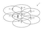
図1は、本実施形態の位置測定システム1の構成を例示するブロック図である。本実施形態の位置測定システム1は、複数の基地局2と、その複数の基地局2と通信可能な携帯電話機3とを含んでいる。携帯電話機3は、その複数の基地局2の少なくとも1つと通信可能に構成され、好ましくは、3つ以上の基地局2と同時に通信可能に構成されている。 FIG. 1 is a block diagram illustrating the configuration of a position measurement system 1 according to this embodiment. The position measurement system 1 according to the present embodiment includes a plurality of
図2は、基地局2と携帯電話機3との構成を例示するブロック図である。携帯電話機3は、タイミング制御部11と、PRACH(Physical Random Access Channel:物理ランダムアクセスチャネル)信号発生部12と、DPCH(Dedicated Physical Channel:個別物理チャネル)信号検出部13と、位置計算部14とを含んでいる。また、携帯電話機3は、後述する遅延時間DTに関する情報を保持している。 FIG. 2 is a block diagram illustrating the configuration of the
タイミング制御部11は、複数の基地局2から送信される同期チャネルを受信して、その基地局2と携帯電話機3とのフレーム同期とスロット同期を取る機能ブロックである。タイミング制御部11は、複数の基地局2の各々からの同期チャネル(SCH)から、フレーム同期とスロット同期のタイミングを検出し、PRACH信号の発生・送信タイミングと、DPCH信号の受信タイミングを検出する。 The
また、タイミング制御部11は、後述するPRACH信号発生部12と後述するDPCH信号検出部13とからの信号の時間差を検出し、その時間差を後述する位置計算部14へ通知する。また、タイミング制御部11は、各基地局2から送信される、予め定められた位置情報21を、位置計算部14へ通知する。 Further, the
PRACH信号発生部12は、そのタイミング制御部11から指示されるタイミングに従って、PRACHチャネルを使って、特定のビットパターンを持つ上り信号を発生させる機能ブロックである。PRACH信号発生部12は、PRACHを用いた上りチャネルにおいて、タイミング制御部11から指示されるタイミングで、ある特定のビットパターンの信号を発生させて、基地局2へ向けて送信する。 The PRACH
DPCH信号検出部13は、基地局2から送信されるDPCHチャネルを受信して、その中から、ある特定のビットパターンを検出し、その受信タイミングをタイミング制御部11へ通知する機能ブロックである。位置計算部14は、タイミング制御部11から通知される、複数の基地局2の各々から受け取った信号の時間差と、複数の基地局2の各々の位置情報21から、携帯電話機3が存在する位置を計算する機能ブロックである。 The DPCH
複数の基地局2の各々は、記憶部15と、PRACH上り信号検出部16と、基地局タイミング制御部17と、DPCH信号発生部18とを含んでいる。 Each of the plurality of
記憶部15は、基地局2に備えられた情報記憶装置である。記憶部15は、各基地局2の位置を示す位置情報21を保持している。PRACH上り信号検出部16は、携帯電話機3より送信されるPRACHチャネルを受信して、特定ビットパターンを検出する機能ブロックである。PRACH上り信号検出部16は、その検出タイミングを、後述する基地局タイミング制御部17へ通知する。 The
基地局タイミング制御部17は、PRACH上り信号検出部16から通知されるPRACH信号の受信タイミングと、事前に定められた待ち時間(遅延時間DT)から、後述するDPCH信号発生部18へ指示する特定ビットパターンの発生タイミングDPCHを用いた送信を指示する機能ブロックである。 The base station
DPCH信号発生部18は、基地局タイミング制御部17から指示されるタイミングで、ある特定ビットパターンを、DPCHチャネルを用いて携帯電話機3へ送信する機能ブロックである。また、このDPCH信号発生部18は、特定のビットパターンに加えて、その基地局2の設置位置を示す位置情報21を送信する機能を有する。 The DPCH
以下に、本実施形態の位置測定システム1の動作について説明を行う。図3は、本実施形態の位置測定システム1の動作を例示するシーケンス図である。 Below, operation | movement of the position measurement system 1 of this embodiment is demonstrated. FIG. 3 is a sequence diagram illustrating the operation of the position measurement system 1 of this embodiment.
ステップS101において、タイミング制御部11は、PRACH信号発生部12に、特定のビットパターンをPRACH上り信号検出部16へ送信するよう指示を出力する。ステップS102において、PRACH信号発生部12は、その命令に応答して、時刻t1のタイミングで、特定のビットパターンをPRACH上り信号検出部16へ送信する。 In step S <b> 101, the
PRACH上り信号検出部16は、PRACH信号発生部12から送信された特定のビットパターンを検出する。ステップS103において、PRACH上り信号検出部16は、その検出タイミング(時刻t2)を、基地局タイミング制御部17へ通知する。 The PRACH uplink
ステップS104において、基地局タイミング制御部17は、DPCH信号発生部18へ、特定のビットパターンの発生を支持する。このとき基地局タイミング制御部17は、PRACH上り信号検出部16から通知された検出タイミング(時刻t2)から、予め定められた待ち時間(DT)を経過した後のタイミング(時刻t3)で、DPCHを用いて、基地局2へ送信するように指示を出す。 In step S104, the base station
ステップS105において、DPCH信号発生部18は、基地局タイミング制御部17から指示されたタイミング(時刻t3)に、特定のビットパターンを発生させる。DPCH信号発生部18は、さらに、その基地局2の設置位置を示す位置情報21を特定のビットパターンに追加して、DPCHを用いて携帯電話機3へ送信する。 In step S105, the DPCH
携帯電話機3のDPCH信号検出部13は、DPCH信号発生部18からDPCHを用いて送信された信号を受信し、その信号に含まれる特定のビットパターンを検出する。ステップS106において、DPCH信号検出部13は、その検出タイミング(時刻t4)を示す情報をタイミング制御部11へ通知する。 The
タイミング制御部11は、DPCH信号検出部13から通知されたタイミング(時刻t4)と、時刻t1の差から、信号の往復に要した時間
往復時間:t4−t1
を計算する。タイミング制御部11は、その往復時間から、さらに、基地局2での待ち時間(遅延時間DT)を差し引くことで
実質往復時間:(t4−t1)−DT
を計算する。タイミング制御部11は、その実質往復時間を、無線信号が往復するのに必要な時間とする。さらに、その半分{(t4−t1)−DT}/2を計算することで、携帯電話機と基地局の間を無線電波が伝播するに要する伝播時間を得る。The
Calculate The
Calculate The
ステップS107において、タイミング制御部11は、算出した伝播時間に関する情報を位置計算部14に供給する。さらに、ステップS108において、DPCH信号検出部13は、基地局2の位置情報21を位置計算部14に供給する。 In step S <b> 107, the
位置計算部14は、複数の基地局2の各々から受け取った信号の時間差をタイミング制御部11から受け取り、各基地局2の位置情報21をDPCH信号検出部13から受け取って、携帯電話機3が存在する位置を計算する。 The
上述のように、本実施形態の位置測定システム1では、携帯電話から基地局へ、基地局から送信されるP−SCH(Primary Synchronization Channel)/S−SCH(Secondary Synchronization Channel)信号によって規定されるフレームとスロットに同期したタイミングで信号を送信する。それを受信した基地局で、予め定められた時間後に、携帯電話に向けて信号を送信する。携帯電話機側では、携帯電話機と基地局間での信号の往復時間を、拡散信号のChip単位で測定する。このようにして、位置測定システム1では、携帯電話機3から複数の基地局2へ信号を送信し、それを受信した基地局2から送信される信号を、携帯電話機3が受信するまでの時間から、各基地局2と携帯電話機3の間の距離を測定しているので、GPS機能などに依存することなく携帯電話機3の位置を推定することができる。 As described above, in the position measurement system 1 of the present embodiment, it is defined by the P-SCH (Primary Synchronization Channel) / S-SCH (Secondary Synchronization Channel) signal transmitted from the base station to the base station. A signal is transmitted at a timing synchronized with the frame and the slot. The base station that has received the signal transmits a signal to the mobile phone after a predetermined time. On the mobile phone side, the round trip time of the signal between the mobile phone and the base station is measured in units of chip of the spread signal. Thus, in the position measurement system 1, a signal is transmitted from the
以上、本願発明の実施の形態を具体的に説明した。本願発明は上述の実施の形態に限定されるものではなく、その要旨を逸脱しない範囲で種々変更可能である。 The embodiment of the present invention has been specifically described above. The present invention is not limited to the above-described embodiment, and various modifications can be made without departing from the scope of the invention.
1…位置測定システム
2…基地局
3…携帯電話機
11…タイミング制御部
12…PRACH信号発生部
13…DPCH信号検出部
14…位置計算部
15…記憶部
16…PRACH上り信号検出部
17…基地局タイミング制御部
18…DPCH信号発生部
21…位置情報
DT…遅延時間DESCRIPTION OF SYMBOLS 1 ...
Claims (14)
Translated fromJapanese前記携帯電話機と無線通信可能な複数の基地局と
を具備し、
前記携帯電話機は、
前記複数の基地局のうちの特定基地局から供給される同期チャネルに応答して、前記特定基地局とのフレーム同期とスロット同期とを実行するタイミング制御部と、
前記特定基地局に供給するPRACH信号を送信するPRACH信号発生部と、
前記PRACH信号に応答して前記特定基地局から供給されるDPCH信号を検出するDPCH信号検出部と、
前記PRACH信号の送信タイミングと前記DPCH信号の検出タイミングとの時間差と、前記特定基地局から供給される位置情報とに基づいて、前記携帯電話機の位置を計算する位置計算部とを備える
位置測定システム。A mobile phone,
A plurality of base stations capable of wireless communication with the mobile phone;
The mobile phone is
A timing control unit that performs frame synchronization and slot synchronization with the specific base station in response to a synchronization channel supplied from the specific base station of the plurality of base stations;
A PRACH signal generator for transmitting a PRACH signal to be supplied to the specific base station;
A DPCH signal detector for detecting a DPCH signal supplied from the specific base station in response to the PRACH signal;
A position measurement system comprising: a position calculator that calculates a position of the mobile phone based on a time difference between a transmission timing of the PRACH signal and a detection timing of the DPCH signal and position information supplied from the specific base station .
前記タイミング制御部は、
前記PRACH信号を送信するタイミングを示す送信命令を出力し、
前記PRACH信号発生部は、
前記タイミング制御部からの送信命令に応じたタイミングで前記PRACH信号を前記特定基地局に送信する
位置測定システム。The position measurement system according to claim 1,
The timing controller is
Outputting a transmission command indicating the timing of transmitting the PRACH signal;
The PRACH signal generator is
A position measurement system that transmits the PRACH signal to the specific base station at a timing according to a transmission command from the timing control unit.
前記DPCH信号検出部は、
前記DPCH信号から第1のビットパターンの信号を抽出し、抽出した前記第1のビットパターンの信号の受信タイミングを示す受信タイミング情報を前記タイミング制御部に通知し、
前記タイミング制御部は、
前記送信命令と前記受信タイミング情報とに基づいて、前記時間差を算出し、
前記位置計算部は、
前記タイミング制御部が算出した前記時間差と、前記位置情報とに基づいて、前記携帯電話機の位置を計算する
位置測定システム。The position measurement system according to claim 2,
The DPCH signal detector is
Extracting a first bit pattern signal from the DPCH signal, and notifying the timing control unit of reception timing information indicating a reception timing of the extracted first bit pattern signal;
The timing controller is
Based on the transmission command and the reception timing information, to calculate the time difference,
The position calculator is
A position measurement system that calculates the position of the mobile phone based on the time difference calculated by the timing control unit and the position information.
前記PRACH信号発生部は、
PRACHチャネルを使用して、第2のビットパターンを持つ上り信号を前記PRACH信号として前記特定基地局に供給する
位置測定システム。The position measurement system according to claim 3.
The PRACH signal generator is
A position measurement system that uses an PRACH channel to supply an uplink signal having a second bit pattern to the specific base station as the PRACH signal.
前記複数の基地局の各々は、
前記携帯電話機から供給される前記第2のビットパターンを持つ上り信号から、前記第2のビットパターンを抽出するPRACH上り信号検出部と、
前記携帯電話機に供給する前記DPCH信号のタイミングを制御する基地局タイミング制御部と、
前記特定基地局タイミング制御部からの命令に応答して、DPCHチャネルを使用して前記第1のビットパターンを有する信号を前記DPCH信号として送信するDPCH信号発生部と
を備える
位置測定システム。The position measurement system according to claim 4,
Each of the plurality of base stations is
A PRACH uplink signal detection unit that extracts the second bit pattern from an uplink signal having the second bit pattern supplied from the mobile phone;
A base station timing control unit for controlling the timing of the DPCH signal supplied to the mobile phone;
A DPCH signal generation unit that transmits a signal having the first bit pattern as the DPCH signal using a DPCH channel in response to a command from the specific base station timing control unit.
前記PRACH上り信号検出部は、
前記第2のビットパターンを抽出したタイミングを示す抽出タイミング情報を前記特定基地局タイミング制御部に通知し、
前記特定基地局タイミング制御部は、
前記抽出タイミング情報と予め設定された遅延時間とに基づいて、前記DPCH信号のタイミングを制御する
位置測定システム。The position measurement system according to claim 5,
The PRACH uplink signal detection unit is
Notifying the specific base station timing control unit of extraction timing information indicating the timing of extracting the second bit pattern,
The specific base station timing controller is
A position measurement system that controls the timing of the DPCH signal based on the extraction timing information and a preset delay time.
(a)前記複数の基地局のうちの特定基地局から供給される同期チャネルに応答して、前記特定基地局とのフレーム同期とスロット同期とを実行するステップと、
(b)前記特定基地局に供給するPRACH信号を送信するステップと、
(c)前記特定基地局から供給されるDPCH信号を検出するステップと、
(d)前記PRACH信号の送信タイミングと前記DPCH信号の検出タイミングとの時間差と、前記特定基地局から供給される位置情報とに基づいて、前記携帯電話機の位置を計算するステップと
を備える
位置測定方法。A position measurement method executed by a position measurement system comprising a mobile phone and a plurality of base stations capable of wireless communication with the mobile phone,
(A) executing frame synchronization and slot synchronization with the specific base station in response to a synchronization channel supplied from the specific base station of the plurality of base stations;
(B) transmitting a PRACH signal to be supplied to the specific base station;
(C) detecting a DPCH signal supplied from the specific base station;
(D) calculating a position of the mobile phone based on a time difference between the transmission timing of the PRACH signal and the detection timing of the DPCH signal and position information supplied from the specific base station. Method.
前記(a)ステップは、
前記PRACH信号を送信するタイミングを示す送信命令を出力するステップを含み、
前記(b)ステップは、
前記送信命令に応じたタイミングで前記PRACH信号を前記特定基地局に送信するステップを含む
位置測定方法。The position measuring method according to claim 7,
The step (a) includes:
Outputting a transmission command indicating a timing of transmitting the PRACH signal;
The step (b)
A position measurement method comprising the step of transmitting the PRACH signal to the specific base station at a timing according to the transmission command.
前記(c)ステップは、
前記DPCH信号から、第1のビットパターンの信号を抽出するステップと、
抽出した前記第1のビットパターンの信号の受信タイミングを示す受信タイミング情報を通知するステップと
前記(d)ステップは、
前記送信命令と前記受信タイミング情報とに基づいて算出された時間差と、前記位置情報とに基づいて、前記携帯電話機の位置を計算するステップを含む
位置測定方法。The position measurement method according to claim 8,
The step (c) includes:
Extracting a first bit pattern signal from the DPCH signal;
A step of notifying reception timing information indicating a reception timing of the extracted signal of the first bit pattern; and the step (d),
A position measurement method, comprising: calculating a position of the mobile phone based on a time difference calculated based on the transmission command and the reception timing information and the position information.
前記(b)ステップは、
PRACHチャネルを使用して、第2のビットパターンを持つ上り信号を前記PRACH信号として前記特定基地局に供給するステップを含む
位置測定方法。The position measuring method according to claim 9, wherein
The step (b)
A position measurement method comprising the step of supplying an uplink signal having a second bit pattern to the specific base station as the PRACH signal using a PRACH channel.
(e)前記携帯電話機から供給される前記第2のビットパターンを持つ上り信号から、前記第2のビットパターンを抽出するステップと、
(f)前記携帯電話機に供給する前記DPCH信号のタイミングを制御するステップと、
(g)所定の送信指示に応答して、DPCHチャネルを使用して前記第1のビットパターンを有する信号を前記DPCH信号として送信するステップと
を備える
位置測定方法。The position measurement method according to claim 10, further comprising:
(E) extracting the second bit pattern from an upstream signal having the second bit pattern supplied from the mobile phone;
(F) controlling the timing of the DPCH signal supplied to the mobile phone;
(G) transmitting a signal having the first bit pattern as the DPCH signal using a DPCH channel in response to a predetermined transmission instruction.
前記(e)ステップは、
前記第2のビットパターンを抽出したタイミングを示す抽出タイミング情報を通知するステップを含み、
前記(f)ステップは、
前記抽出タイミング情報と予め設定された遅延時間とに基づいて、前記DPCH信号のタイミングを制御するステップを含む
位置測定方法。The position measuring method according to claim 10,
The step (e) includes:
Notifying extraction timing information indicating the timing at which the second bit pattern is extracted,
The step (f)
A position measurement method comprising the step of controlling the timing of the DPCH signal based on the extraction timing information and a preset delay time.
前記特定基地局に供給するPRACH信号を送信するPRACH信号発生部と、
前記PRACH信号に応答して前記特定基地局から供給されるDPCH信号を検出するDPCH信号検出部と、
前記PRACH信号の送信タイミングと前記DPCH信号の検出タイミングとの時間差と、前記特定基地局から供給される位置情報とに基づいて、前記携帯電話機の位置を計算する位置計算部と
を具備し、
前記タイミング制御部は、
前記PRACH信号を送信するタイミングを示す送信命令を出力し、
前記PRACH信号発生部は、
前記タイミング制御部からの送信命令に応じたタイミングで、PRACHチャネルを使用して、第1のビットパターンを持つ上り信号を前記PRACH信号として前記特定基地局に供給し、
前記DPCH信号検出部は、
前記DPCH信号から第1のビットパターンの信号を抽出し、抽出した前記第1のビットパターンの信号の受信タイミングを示す受信タイミング情報を前記タイミング制御部に通知し、
前記タイミング制御部は、
前記送信命令と前記受信タイミング情報とに基づいて、前記時間差を算出し、
前記位置計算部は、
前記タイミング制御部が算出した前記時間差と、前記位置情報とに基づいて、前記携帯電話機の位置を計算する
携帯電話機。A timing control unit that performs frame synchronization and slot synchronization with the specific base station in response to a synchronization channel supplied from the specific base station of the plurality of base stations;
A PRACH signal generator for transmitting a PRACH signal to be supplied to the specific base station;
A DPCH signal detector for detecting a DPCH signal supplied from the specific base station in response to the PRACH signal;
A position calculator that calculates the position of the mobile phone based on the time difference between the transmission timing of the PRACH signal and the detection timing of the DPCH signal and the position information supplied from the specific base station,
The timing controller is
Outputting a transmission command indicating the timing of transmitting the PRACH signal;
The PRACH signal generator is
Using a PRACH channel at a timing according to a transmission command from the timing control unit, an uplink signal having a first bit pattern is supplied to the specific base station as the PRACH signal,
The DPCH signal detector is
Extracting a first bit pattern signal from the DPCH signal, and notifying the timing control unit of reception timing information indicating a reception timing of the extracted first bit pattern signal;
The timing controller is
Based on the transmission command and the reception timing information, to calculate the time difference,
The position calculator is
A mobile phone that calculates the position of the mobile phone based on the time difference calculated by the timing control unit and the position information.
(a)複数の基地局のうちの特定基地局から供給される同期チャネルに応答して、前記特定基地局とのフレーム同期とスロット同期とを実行するステップと、
(b)前記特定基地局に供給するPRACH信号を送信するステップと、
(c)前記PRACH信号に応答して前記特定基地局から供給されるDPCH信号を検出するステップと、
(d)前記PRACH信号の送信タイミングと前記DPCH信号の検出タイミングとの時間差と、前記特定基地局から供給される位置情報とに基づいて、前記携帯電話機の位置を計算するステップと
を具備し、
前記(a)ステップは、
前記PRACH信号を送信するタイミングを示す送信命令を出力するステップを含み、
前記(b)ステップは、
前送信命令に応じたタイミングで、PRACHチャネルを使用して、第1のビットパターンを持つ上り信号を前記PRACH信号として前記特定基地局に供給するステップを含み、
前記(c)ステップは、
前記DPCH信号から第1のビットパターンの信号を抽出するステップと、
抽出した前記第1のビットパターンの信号の受信タイミングを示す受信タイミング情報を通知するステップと
を含み、
前記(d)ステップは、
前記送信命令と前記受信タイミング情報とに基づいて算出された前記時間差と、前記位置情報とに基づいて、前記携帯電話機の位置を計算するステップを含む
位置測定プログラム。A position measurement program showing a procedure for measuring the position of a mobile phone,
(A) executing frame synchronization and slot synchronization with the specific base station in response to a synchronization channel supplied from a specific base station of the plurality of base stations;
(B) transmitting a PRACH signal to be supplied to the specific base station;
(C) detecting a DPCH signal supplied from the specific base station in response to the PRACH signal;
(D) calculating the position of the mobile phone based on the time difference between the transmission timing of the PRACH signal and the detection timing of the DPCH signal and the position information supplied from the specific base station,
The step (a) includes:
Outputting a transmission command indicating a timing of transmitting the PRACH signal;
The step (b)
Supplying an uplink signal having a first bit pattern to the specific base station as the PRACH signal using a PRACH channel at a timing according to a previous transmission command;
The step (c) includes:
Extracting a signal of a first bit pattern from the DPCH signal;
Notifying reception timing information indicating a reception timing of the extracted signal of the first bit pattern,
The step (d) includes:
A position measurement program, comprising: calculating a position of the mobile phone based on the time difference calculated based on the transmission command and the reception timing information and the position information.
Priority Applications (1)
| Application Number | Priority Date | Filing Date | Title |
|---|---|---|---|
| JP2009042652AJP2010199991A (en) | 2009-02-25 | 2009-02-25 | Location measuring system |
Applications Claiming Priority (1)
| Application Number | Priority Date | Filing Date | Title |
|---|---|---|---|
| JP2009042652AJP2010199991A (en) | 2009-02-25 | 2009-02-25 | Location measuring system |
Publications (1)
| Publication Number | Publication Date |
|---|---|
| JP2010199991Atrue JP2010199991A (en) | 2010-09-09 |
Family
ID=42824247
Family Applications (1)
| Application Number | Title | Priority Date | Filing Date |
|---|---|---|---|
| JP2009042652AWithdrawnJP2010199991A (en) | 2009-02-25 | 2009-02-25 | Location measuring system |
Country Status (1)
| Country | Link |
|---|---|
| JP (1) | JP2010199991A (en) |
Cited By (2)
| Publication number | Priority date | Publication date | Assignee | Title |
|---|---|---|---|---|
| JP2014526164A (en)* | 2011-06-28 | 2014-10-02 | クゥアルコム・インコーポレイテッド | Distributed positioning mechanism for wireless communication devices |
| US9332383B2 (en) | 2011-09-19 | 2016-05-03 | Qualcomm Incorporated | Time of arrival based positioning system |
- 2009
- 2009-02-25JPJP2009042652Apatent/JP2010199991A/ennot_activeWithdrawn
Cited By (2)
| Publication number | Priority date | Publication date | Assignee | Title |
|---|---|---|---|---|
| JP2014526164A (en)* | 2011-06-28 | 2014-10-02 | クゥアルコム・インコーポレイテッド | Distributed positioning mechanism for wireless communication devices |
| US9332383B2 (en) | 2011-09-19 | 2016-05-03 | Qualcomm Incorporated | Time of arrival based positioning system |
Similar Documents
| Publication | Publication Date | Title |
|---|---|---|
| NZ600677A (en) | Method and arrangement of determining timing uncertainty | |
| KR101343304B1 (en) | A method and an apparatus for synchronization among the neighboring base stations in the wireless communication system | |
| KR20130085357A (en) | Method and device for establishing uplink synchronization | |
| PH12018501953A1 (en) | Ue reported srs swtching capability | |
| WO2008008685A3 (en) | Wireless access network base station and method for determining location information for a mobile station using uplink time-difference of arrival | |
| RU2008132875A (en) | METHOD AND DEVICE FOR PERFORMING THE PROCEDURE OF TEMPORARY SYNCHRONIZATION OF THE RISING COMMUNICATION LINES WHEN TRANSFERRING SERVICE IN THE MOBILE COMMUNICATION SYSTEM | |
| WO2010095888A3 (en) | Method and apparatus for handover by calculating the distance between a mobile user equipment and an intermediate access point in a wireless communication system | |
| JP5117507B2 (en) | Wireless communication system, synchronization method between base stations, and base station | |
| WO2010135090A3 (en) | Systems, apparatus and methods for interference management on uplink channels in wireless communication systems | |
| WO2012099412A3 (en) | Method and apparatus for transmitting an uplink signal by a relay in a wireless communication system | |
| NZ595555A (en) | Selecting signal power measurement method based on determined timing for a base station | |
| WO2011031064A3 (en) | Method and apparatus for transceiving a signal in a communication system | |
| WO2009082728A3 (en) | Methods, systems and apparatus for integrated wireless device location determination | |
| WO2012046985A3 (en) | Apparatus and method for controlling mdt measurement report in 3gpp system | |
| RU2014150510A (en) | METHODS AND DEVICES FOR DETERMINING THE ASSESSMENT OF SIGNAL POWER BY MEASURING ZOOM | |
| US20170339527A9 (en) | Method and Apparatus for Indoor Location Estimation Among Peer-To-Peer Devices | |
| WO2012019321A8 (en) | Automatic guard period adjustment in time division duplexed wireless communication | |
| NO20035020D0 (en) | Channel quality metrics for down-line resource allocation | |
| RU2012153169A (en) | METHODS AND DEVICES FOR SUPPORTING INTERFREQUENCY MEASUREMENTS | |
| US20160337808A1 (en) | Method and Apparatus for Indoor Location Estimation Among Peer-To-Peer Devices | |
| WO2013009775A3 (en) | Methods and apparatuses for low -overhead wireless beacons having next full beacon time indications | |
| WO2013036058A3 (en) | Method and apparatus for channel estimation in a distributed multi-node system | |
| PH12022553245A1 (en) | User equipment positioning estimate for specified time | |
| WO2009038075A1 (en) | User device, base station device, and method used in mobile communication system | |
| WO2008090592A1 (en) | Intermittent communication system, base station apparatus, and mobile station apparatus |
Legal Events
| Date | Code | Title | Description |
|---|---|---|---|
| A300 | Withdrawal of application because of no request for examination | Free format text:JAPANESE INTERMEDIATE CODE: A300 Effective date:20120501 |