JP2010199672A - Stand for flat screen tv - Google Patents
Stand for flat screen tvDownload PDFInfo
- Publication number
- JP2010199672A JP2010199672AJP2009038968AJP2009038968AJP2010199672AJP 2010199672 AJP2010199672 AJP 2010199672AJP 2009038968 AJP2009038968 AJP 2009038968AJP 2009038968 AJP2009038968 AJP 2009038968AJP 2010199672 AJP2010199672 AJP 2010199672A
- Authority
- JP
- Japan
- Prior art keywords
- thin
- stand
- frame
- acceleration sensor
- body case
- Prior art date
- Legal status (The legal status is an assumption and is not a legal conclusion. Google has not performed a legal analysis and makes no representation as to the accuracy of the status listed.)
- Pending
Links
- 230000001133accelerationEffects0.000claimsabstractdescription21
- 230000003028elevating effectEffects0.000claimsdescription12
- 230000001174ascending effectEffects0.000claimsdescription8
- 239000004973liquid crystal related substanceSubstances0.000description7
- 238000000034methodMethods0.000description5
- 230000000630rising effectEffects0.000description5
- 239000007787solidSubstances0.000description3
- 239000002184metalSubstances0.000description2
- 239000011347resinSubstances0.000description2
- 229920005989resinPolymers0.000description2
- 229910000831SteelInorganic materials0.000description1
- 230000004308accommodationEffects0.000description1
- 238000005452bendingMethods0.000description1
- 230000001276controlling effectEffects0.000description1
- 230000003111delayed effectEffects0.000description1
- 239000000428dustSubstances0.000description1
- 239000000463materialSubstances0.000description1
- 230000001105regulatory effectEffects0.000description1
- 239000010959steelSubstances0.000description1
- 239000010409thin filmSubstances0.000description1
Images


Landscapes
- Devices For Indicating Variable Information By Combining Individual Elements (AREA)
Abstract
Description
Translated fromJapanese本発明は、液晶TVなどの薄型TV用スタンドに関する。 The present invention relates to a thin TV stand such as a liquid crystal TV.
最近、液晶TVやプラズマTVなどの薄型TVが普及してきている。また、画面サイズの大型化が進んでおり、これらの薄型TVを室内に設置するために、薄型TVを直立姿勢に保持する専用スタンドが提供されている。 Recently, thin TVs such as liquid crystal TVs and plasma TVs have become widespread. Further, the screen size has been increased, and in order to install these thin TVs indoors, a dedicated stand for holding the thin TVs in an upright posture is provided.
しかし、画面サイズが大きな薄型TVであれば、揺れや衝撃に対して転倒しやすい構成となり、地震などにより大きな揺れが発生したときに転倒してしまう虞が生じる。特に日本のような地震国では、頻繁に地震が発生するので、薄型TVを、ただ直立姿勢に保持するだけの専用スタンドでは十分安全とは言えない。 However, a thin TV with a large screen size has a configuration that easily falls over when it is shaken or impacted, and there is a risk that it will fall down when a large shake occurs due to an earthquake or the like. Especially in earthquake-prone countries like Japan, earthquakes frequently occur, so a dedicated stand that simply holds a flat-screen TV in an upright position is not safe enough.
そのために、液晶TVをフレームベースに固定して、このフレームベースをケース内部と外部とに昇降自在とし、液晶TVを視聴しないときにはケースに収納するとした液晶テレビ収納ケースが既に提案されている(例えば、特許文献1参照)。 For this reason, there has already been proposed a liquid crystal television storage case in which the liquid crystal TV is fixed to the frame base, the frame base can be moved up and down inside and outside the case, and stored in the case when the liquid crystal TV is not viewed (for example, , See Patent Document 1).
しかし、特許文献1に記載された収納ケースは、スイッチ操作によって液晶TVを昇降するものであって、揺れを感知して収納するものではないので、液晶TVを視聴中に地震が発生した際には、対応が遅れるという問題を生じる。 However, since the storage case described in
また、TVは、スイッチを入れてすぐに見たいときがあり、さらに、室内に設置するTVは、室内のインテリアの一部であるので、TVを見ないときにも、室内でその姿が見える状態に設置しておくことが好ましい。 In addition, there are times when you want to watch the TV immediately after switching it on. Furthermore, since the TV installed in the room is part of the interior of the room, you can see it when you are not watching the TV. It is preferable to install in a state.
しかし、薄型TVは転倒しやすい構成であるので、地震などにより大きな揺れが発生したときには、転倒を防止する構成とすることが好ましい。そのために、薄型TVが倒れる虞が生じる程度の大きな揺れが発生したときに、スタンドの上に直立している薄型TVを保護する機能を備える専用スタンドの開発が望まれる。 However, since a thin TV has a configuration that easily falls, it is preferable to have a configuration that prevents a fall when a large shake occurs due to an earthquake or the like. For this reason, it is desired to develop a dedicated stand having a function of protecting the thin TV standing upright on the stand when a large shaking that may cause the thin TV to fall is generated.
本発明は、上記問題点に鑑み、画面サイズの大きな薄型TVであっても、地震などによりの大きな揺れが発生したときに、薄型TVの転倒を防止して保護する機能を有する薄型TV用スタンドを提供することを目的とする。 In view of the above problems, the present invention is a thin TV stand having a function of preventing and protecting a thin TV from overturning when a large shake due to an earthquake or the like occurs even in a thin TV having a large screen size. The purpose is to provide.
上記目的を達成するために本発明は、薄型TVをその上部に設ける開口部から出し入れして視聴位置に立設すると共にその内部に収納可能な本体ケースと、薄型TVを視聴位置と収納位置とに昇降移動する昇降手段と、揺れを感知する加速度センサと、該加速度センサからの信号を受信して前記昇降手段を制御する制御部とを備え、前記加速度センサが感知した揺れが予め設定された所定の揺れ以上の大きさと前記制御部が判定したときに、前記昇降手段を駆動して前記本体ケース内に薄型TVを収納する構成の薄型TV用スタンドとしたことを特徴としている。 In order to achieve the above object, the present invention provides a main body case that can be stowed and stowed in a viewing position by inserting / removing a thin TV from an opening provided in the upper portion thereof, and a viewing position and a housing position of the thin TV. Lifting and lowering means that moves up and down, an acceleration sensor that senses shaking, and a control unit that receives the signal from the acceleration sensor and controls the raising and lowering means, and the shaking sensed by the acceleration sensor is preset. When the control unit determines that the magnitude is greater than or equal to a predetermined amount of shaking, the elevating means is driven to form a thin TV stand configured to store the thin TV in the main body case.
この構成によると、地震などにより大きな揺れが発生したときに、直ちに薄型TVを本体ケース内に収納することができ、薄型TVの転倒を防止して保護することが可能な薄型TV用スタンドとなる。 According to this configuration, when a large shake occurs due to an earthquake or the like, the thin TV can be immediately stored in the main body case, and the thin TV stand can be protected by preventing the thin TV from falling. .
また本発明は、上記構成の薄型TV用スタンドにおいて、前記本体ケースが、堅固に構成されたフレーム枠と該フレーム枠をカバーすると共に前記開口部を有する外装カバーを備え、前記昇降手段を前記フレーム枠に装着したことを特徴としている。この構成によると、薄型TVを昇降手段を介して堅固に支持可能であり、本体ケース内に収納した薄型TVを確実に保護可能な薄型TV用スタンドとなる。 Further, according to the present invention, in the thin TV stand having the above-described configuration, the main body case includes a rigidly configured frame frame and an exterior cover that covers the frame frame and has the opening, and the lifting means is mounted on the frame. It is characterized by being attached to a frame. According to this configuration, the thin TV can be firmly supported through the lifting / lowering means, and the thin TV stand that can reliably protect the thin TV stored in the main body case is obtained.
また本発明は、上記構成の薄型TV用スタンドにおいて、前記昇降手段が、上下方向に周回する周回ベルトを正逆転して昇降操作する装置であって、前記フレーム枠に上下一対のシャフトを並行して設け、下シャフトに駆動ローラを回転自在に取り付け、上シャフトに従動ローラを回転自在に取り付け、前記周回ベルトをこれらのローラに巻回し、該周回ベルトに取付部材を介して薄型TVを装着して、前記駆動ローラを回転駆動する駆動モータを正逆転して昇降操作することを特徴としている。この構成によると、駆動ローラを支持する下シャフトと従動ローラを支持する上シャフトが堅固なフレーム枠に支持されるので、周回ベルトに装着する薄型TVを安定して昇降させることができる。 In the thin TV stand having the above-described configuration, the lifting and lowering means may be operated to move up and down by rotating a revolving belt that circulates in the vertical direction, and a pair of upper and lower shafts are parallel to the frame frame. The drive roller is rotatably attached to the lower shaft, the driven roller is rotatably attached to the lower shaft, the belt is wound around these rollers, and a thin TV is mounted on the belt through an attachment member. The drive motor for rotating the drive roller is moved up and down to move up and down. According to this configuration, since the lower shaft that supports the driving roller and the upper shaft that supports the driven roller are supported by the rigid frame frame, it is possible to stably raise and lower the thin TV attached to the circulating belt.
また本発明は、上記構成の薄型TV用スタンドにおいて、前記取付部材の位置を感知して、前記取付部材に装着された薄型TVの視聴位置となる上昇端と、収納位置となる下降端とを規定することを特徴としている。この構成によると、装着する薄型TVのタイプやサイズに拘らずに、視聴位置と収納位置とに安定して移動することができる。 Further, according to the present invention, in the thin TV stand having the above-described configuration, the position of the mounting member is sensed, and an ascending end serving as a viewing position of the thin TV mounted on the mounting member and a descending end serving as a storage position are provided. It is characterized by prescribing. According to this configuration, it is possible to move stably between the viewing position and the storage position regardless of the type and size of the thin TV to be mounted.
また本発明は、上記構成の薄型TV用スタンドにおいて、前記周回ベルトが幅広の歯付きベルトであり、前記駆動ローラと前記従動ローラが歯付きローラであることを特徴としている。この構成によると、周回ベルトのベルト強度が高く耐荷重性が大きくなって、比較的大型の薄型TVも昇降自在に装着することができる。 According to the present invention, in the thin TV stand having the above-described configuration, the rotating belt is a wide toothed belt, and the driving roller and the driven roller are toothed rollers. According to this configuration, the belt strength of the circling belt is high and the load resistance is large, so that a relatively large thin TV can be mounted freely.
また本発明は、上記構成の薄型TV用スタンドにおいて、前記外装カバーに操作スイッチを備える操作部を設け、前記操作スイッチを介して昇降操作可能な構成としたことを特徴としている。この構成によると、手動操作でも昇降自在となるので、地震発生時以外でも任意にスタンド内に収納して保護可能となる。 According to the present invention, in the thin TV stand having the above-described configuration, an operation unit including an operation switch is provided in the exterior cover, and the structure can be moved up and down via the operation switch. According to this configuration, since it can be moved up and down even by manual operation, it can be arbitrarily stored in the stand and protected even when an earthquake occurs.
また本発明は、上記構成の薄型TV用スタンドにおいて、前記操作部に、前記制御部に設定する所定の揺れの大きさを変更可能とする閾値設定ボタンを設けたことを特徴としている。この構成によると、薄型TVのタイプやサイズに応じて、また、TV所有者や薄型TVを設置する周囲の環境に応じて、スタンド内に収納する揺れの大きさを変更できるので、使い勝手のよい薄型TV用スタンドとなる。 According to the present invention, in the thin TV stand having the above-described configuration, a threshold value setting button is provided on the operation unit so as to change a magnitude of a predetermined shaking set in the control unit. According to this configuration, the size of shaking stored in the stand can be changed according to the type and size of the thin TV, and according to the TV owner and the surrounding environment where the flat TV is installed, so it is easy to use. It becomes a stand for thin TV.
また本発明は、上記構成の薄型TV用スタンドにおいて、前記操作部に、前記昇降手段の昇降速度を変更可能とする昇降速度設定ボタンを設けたことを特徴としている。この構成によると、設置する薄型TVのタイプやサイズによって最適な昇降速度に設定可能となり、種々のタイプのTVに対応可能な薄型TV用スタンドとなる。 Further, the present invention is characterized in that, in the thin TV stand having the above-described configuration, an elevation speed setting button is provided on the operation unit so that the elevation speed of the elevation means can be changed. According to this configuration, it is possible to set the optimum lifting speed depending on the type and size of the thin TV to be installed, and the thin TV stand that can be used for various types of TVs.
本発明によれば、薄型TVを収納可能な本体ケースと、薄型TVを視聴位置と収納位置とに昇降移動する昇降手段と、揺れを感知する加速度センサと、該加速度センサからの信号を受信して前記昇降手段を制御する制御部とを備え、前記加速度センサが感知した揺れが予め設定された所定の揺れ以上の大きさと前記制御部が判定したときに、前記昇降手段を駆動して本体ケース内に収納する構成としたので、地震などにより大きな揺れが発生したときに、直ちに薄型TVを本体ケース内に収納することができ、薄型TVの転倒を防止して保護する機能を有する薄型TV用スタンドを得ることができる。 According to the present invention, a main body case capable of storing a thin TV, elevating means for moving the flat TV up and down between a viewing position and a storage position, an acceleration sensor for detecting shaking, and a signal from the acceleration sensor are received. A control unit for controlling the lifting means, and when the control unit determines that the swing sensed by the acceleration sensor is greater than a predetermined swing set in advance, the lifting means is driven to drive the body case Because it is configured to be housed inside, when a large shake occurs due to an earthquake or the like, the thin TV can be immediately stored in the main body case, and it has a function to prevent and protect the thin TV from overturning. You can get a stand.
以下に本発明の実施形態を図面を参照して説明する。また、同一構成部材については同一の符号を用い、詳細な説明は適宜省略する。 Embodiments of the present invention will be described below with reference to the drawings. Moreover, the same code | symbol is used about the same structural member, and detailed description is abbreviate | omitted suitably.
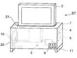
図1に示す本実施形態の薄型TV用スタンドSTは、薄型TV2を収納可能な本体ケース1と、薄型TV2を昇降する昇降手段3とを備え、本体ケース1の上部に設ける開口部21から薄型TV2を出し入れして、視聴位置と収納位置とに昇降移動するスタンドである。 A thin-screen TV stand ST of the present embodiment shown in FIG. 1 includes a
また、本体ケース1に揺れを感知する加速度センサ4と、該加速度センサ4からの信号を受信して揺れの大きさを判定して昇降手段3を制御する制御部5を設け、該制御部5が予め設定される所定以上の揺れと判定したときに、昇降手段3を駆動して視聴位置に立設している薄型TV2を本体ケース1内に収納する構成としている。 Further, the
そのために、地震などにより大きな揺れが発生したときに、加速度センサ4が感知した揺れの大きさが予め設定される所定以上の揺れと判定されたときに薄型TV2を本体ケース1内に収納するので、薄型TV2の転倒を防止して保護することができる。 For this reason, when a large shake occurs due to an earthquake or the like, the
本体ケース1は、図2(a)に示すフレーム枠10と、図2(b)に示す外装カバー20とを備えている。フレーム枠10は、例えば金属製の型鋼を枠状に接合したフレームであって堅固な構成とされている。また、フレーム枠10に脚部11や底板(不図示)を設けることができる。外装カバー20は、このフレーム枠10をカバーする外装材であって樹脂板や樹脂成形品を用いることができる。また、開口部21はこの外装カバー20の上面部に形成されている。 The
また、昇降手段3は、堅固な構成のフレーム枠10を利用して装着するようにしている。この構成であれば、フレーム枠10に固定される昇降手段3を介して薄型TV2を堅固に支持可能となる。また、堅固な構成のフレーム枠10内に薄型TV2を収納するので、薄型TV2を確実に保護可能な薄型TV用スタンドとなる。 The elevating
昇降手段3は、例えば上下にスライドする往復動装置や、上下方向に周回する周回装置を正逆転させて用いることができる。本実施形態では、薄型TV2が比較的軽量であるために、駆動ローラと従動ローラとを上下に並行に配置して、このローラ間に周回ベルトを巻回し、駆動ローラを正逆転させて、周回ベルトに装着する薄型TV2を上下に移動する構成としている。 The elevating
また、駆動ローラと従動ローラとをフレーム枠10に装着するために、フレーム枠10に取り付けるバー12(12A、12B)に下シャフト32を取り付け、フレーム枠10に取り付けるバー13(13A、13B)に上シャフト35を取り付け、これらの上下に並行して設けられる一対のシャフトに、駆動ローラおよび従動ローラをそれぞれ回転自在に装着する構成としている。 Further, in order to attach the driving roller and the driven roller to the
この昇降手段3の具体的な構成について図3を用いて説明する。 A specific configuration of the lifting means 3 will be described with reference to FIG.
図3(a)に示すように、バー12に下シャフト32を取り付け、この下シャフト32に駆動ローラ33を回転自在に装着している。また、バー13に上シャフト35を取り付け、この上シャフト35に従動ローラ36を回転自在に装着し、駆動ローラ33と従動ローラ36を巻回する周回ベルト34を装着している。また、駆動ローラ33を回転駆動する駆動モータ31と制御装置5、および、加速度センサ4を備え、該加速度センサ4が感知する揺れの大きさにより制御装置5を介して駆動モータ31の駆動を制御している。制御装置5は各部へ所要の電力を供給する電源供給部も備えており、家庭用電源から直接入力する電力、もしくは、TV用電源から入力する電力を用いることができる。さらに、周回ベルト34に取付部材37を介して薄型TV2を装着して、駆動モータ31を正逆転して薄型TV2を昇降する構成としている。 As shown in FIG. 3A, a
図3(b)に示すように取付部材37は、薄型TV2を周回ベルト34に固定する部材であって、ベルト固定部37aとTV固定部とを有する部材(例えば板金製)を用いることができる。また、TV固定部として、垂直方向の平面状ベルト固定部から水平方向に屈曲して薄型TV2の底面を支持する水平支持部37bと、ベルト固定部と同一平面となる薄型TV2の裏面を支持する垂直支持部37cとのいずれか一方の支持部、もしくはこれら両方の支持部を同時に用いることができる。 As shown in FIG. 3B, the
バー12に下シャフト32を取り付ける方法、バー13に上シャフト35を取り付ける方法は、螺子固定式でも、嵌め込み式でもよく特に限定されない。また、それぞれのシャフトにローラを回転自在に装着するには、ベアリングなどの回転補助部材を用いて装着すればよい。また、駆動モータ31を用いて駆動ローラ33を回転駆動する方法も適宜選択可能であって、図中の31Aに示すギヤ駆動を用いた駆動系や直接駆動系31Bなどの公知の駆動方法から適当な方法を選択することができる。 The method of attaching the
上記のような構成としているので、駆動ローラ33を支持する下シャフト32と従動ローラ36を支持する上シャフト35が堅固な構成のフレーム枠10に支持される構成となり、周回ベルト34に装着する薄型TV2を安定して昇降させることができる。 Since it is configured as described above, the
この際、周回ベルト34は、図3(b)に示すように幅広の歯付きベルトが好ましい。これは幅広の歯付きベルトであれば、ベルト強度が高く耐荷重性が大きいからである。そのために、駆動ローラ33と従動ローラ36も歯付きローラとしている。この構成であれば、周回ベルト34の耐荷重性が大きくなって、比較的大型の薄型TVも昇降自在に装着することができる。 At this time, the
また、昇降移動する薄型TV2の上昇端と下降端とは予め定めておくことが好ましい。これは、上昇端が図中の実線に示す視聴位置2Aとなって、下降端が想像線に示す収納位置2Bとなるからである。また、この上昇端と下降端は、薄型TV2の所定部位を検知して感知することも可能であるが、本実施形態においては、取付部材37の位置から、上昇端と下降端を規定する構成としている。 Moreover, it is preferable that the rising end and the falling end of the
取付部材37の位置により上昇端と下降端を規定するには、取付部材37の所定部位の上昇位置と下降位置にそれぞれリミットスイッチ(不図示)やセンサなどを設けておき、それぞれの位置に到達したことを検知する方法を用いることができる。 In order to define the ascending end and the descending end according to the position of the mounting
このように、取付部材37の位置により薄型TV2の上昇端と下降端を規定する構成であれば、設置する薄型TV2のタイプやサイズに拘らずに、薄型TV2を視聴位置と収納位置とに安定して移動することができるので、種々のタイプのTVに対応可能となって好ましい。さらに、薄型TV2を視聴位置まで上昇したときに、取付部材37が開口部21を塞ぐような形状として、通常の視聴状態では、開口部21から本体ケース1内にゴミや異物が侵入しない構成とすることも可能である。 As described above, if the configuration is such that the rising end and the falling end of the
また、地震でない時に薄型TV2をスタンド内に収納したい場合も想定されるので、昇降操作のための操作スイッチを設けることが好ましい。そのために、本実施形態では、外装カバー20に操作スイッチとなる手動ボタンを有する操作部6(図1参照)を設ける構成としている。この構成であれば、手動操作でも昇降自在となるので、所望のタイミングで任意にスタンド内に収納して保護可能となって使い勝手のよい薄型TV用スタンドとなる。 Further, since it is assumed that the
また、薄型TVをスタンド内に収納開始する揺れの大きさは変更可能であることが好ましい。さらに、昇降速度も変更可能であることが好ましい。これは、設置する薄型TVのタイプやサイズによって倒れやすさも異なり、適した昇降速度も異なる場合があるからである。 Moreover, it is preferable that the magnitude | size of the shake which starts accommodation of a thin TV in a stand can be changed. Furthermore, it is preferable that the raising / lowering speed can also be changed. This is because the ease of falling differs depending on the type and size of the thin TV to be installed, and the appropriate lifting speed may be different.
薄型TVをスタンド内に収納開始する揺れの大きさが変更可能であれば、薄型TVのタイプやサイズに応じて、また、TV所有者や薄型TVを設置する周囲の環境に応じて、スタンド内に収納する揺れの大きさを変更できるので、使い勝手のよい薄型TV用スタンドとなる。さらに、昇降速度が変更可能であれば、設置する薄型TVのタイプやサイズによって最適な昇降速度に設定可能となり、種々のタイプのTVに対応可能な薄型TV用スタンドとなる。 If you can change the size of the shaking to start storing the flat-screen TV in the stand, depending on the type and size of the flat-screen TV, and depending on the TV owner and the surrounding environment where the flat-screen TV is installed, Since the amount of shaking stored in the can be changed, it becomes a convenient thin TV stand. Furthermore, if the ascending / descending speed can be changed, the optimum ascending / descending speed can be set according to the type and size of the thin TV to be installed, and the thin TV stand can be adapted to various types of TVs.
昇降速度を変更可能とするには、駆動モータ31として可変速モータを採用し、操作部6に昇降速度を設定するボタンを設けることで実現可能となる。 In order to be able to change the ascending / descending speed, a variable speed motor is adopted as the
上記したように本実施形態に係る薄型TV用スタンドSTは、本体ケース1の内部に装着している加速度センサ4が揺れを感知すると、その揺れの大きさに応じた信号を制御部5に伝達し、制御部5がこの揺れの大きさが予め規定された所定の揺れ(閾値)よりも大きいと判定したときに、薄型TV2を降下させる方向に駆動モータ31を駆動し、薄型TV2を本体ケース1の内部に収納する。 As described above, when the
揺れが収まると、周囲の安全を確認した跡で操作部6に設ける操作スイッチを操作して、収納されている薄型TV2を視聴位置に上昇することができる。 When the shaking is settled, it is possible to raise the housed
また、操作部6には、閾値となる所定の揺れの大きさを変更して設定するために、閾値設定ボタンや、昇降速度を変更して設定するための昇降速度設定ボタンなどを仕様に応じて設けることができる。 In addition, the
このように、薄型TV2を本体ケース1に収納する揺れの大きさを予め規定しているので、子供のいたずらなどで軽くゆすっただけでは、駆動しない構成とすることができ、また、大きな揺れが発生したときには、自動的に本体ケース内に収納開始するので、安心して薄型TV2を設置することができる。 Thus, since the magnitude | size of the shake which accommodates the thin-
特に、タワーマンションなどの高層住宅内に薄型TV2を設置する際には、地震による揺れも大きくなるので、揺れや衝撃に対して転倒しやすい薄型TV2にとって、特に有効な薄型TV用スタンドSTとなる。 In particular, when a flat-
上記したように、本発明に係る薄型TV用スタンドによれば、薄型TVを収納可能な本体ケースと、薄型TVを視聴位置と収納位置とに昇降移動する昇降手段と、揺れを感知する加速度センサと、該加速度センサからの信号を受信して前記昇降手段を制御する制御部とを備え、前記加速度センサが感知した揺れが予め設定された所定の揺れ以上の大きさと前記制御部が判定したときに、前記昇降手段を駆動して本体ケース内に収納する構成としたので、地震などの大きな揺れが発生したときに、直ちに薄型TVを本体ケース内に収納することができ、薄型TVの転倒を防止して保護する機能を有する薄型TV用スタンドとなる。 As described above, according to the thin TV stand according to the present invention, the main body case capable of storing the thin TV, the elevating means for moving the thin TV up and down between the viewing position and the storage position, and the acceleration sensor for detecting shaking. And a control unit that receives the signal from the acceleration sensor and controls the elevating means, and when the control unit determines that the vibration sensed by the acceleration sensor is greater than or equal to a predetermined vibration set in advance. In addition, since the elevating means is driven and stored in the main body case, when a large shake such as an earthquake occurs, the thin TV can be immediately stored in the main body case, and the thin TV can be overturned. It becomes a thin TV stand having a function of preventing and protecting.
また、本体ケースが、堅固に構成されたフレーム枠を備え、昇降手段を堅固なフレーム枠に装着する構成としているので、薄型TVを堅固に支持可能であり、本体ケース内に収納した薄型TVを確実に保護可能な薄型TV用スタンドとなる。そのために、本体ケース内に収納した後、スタンドが転倒しても、薄型TVの周囲を堅固なフレーム枠で覆っているので、損傷せずに転倒時の被害を抑制することができる。 In addition, since the main body case has a rigid frame frame and the lifting means is mounted on the rigid frame frame, the thin TV can be firmly supported, and the thin TV housed in the main body case It becomes a thin TV stand that can be reliably protected. For this reason, even if the stand falls down after being stored in the main body case, the thin TV is covered with a solid frame frame, so that damage during the fall can be suppressed without being damaged.
さらに、薄型TVをスタンド内に収納開始する揺れの大きさを変更可能とすることで、薄型TVのタイプやサイズに応じて、また、TV所有者や薄型TVを設置する周囲の環境に応じて、スタンド内に収納する揺れの大きさを変更でき、使い勝手のよい薄型TV用スタンドとなる。 Furthermore, by making it possible to change the size of the shaking that starts storing the flat-screen TV in the stand, it depends on the type and size of the flat-screen TV, and also on the TV owner and the surrounding environment where the flat-screen TV is installed. The size of shaking stored in the stand can be changed, and it becomes an easy-to-use thin TV stand.
そのために、本発明に係る薄型TV用スタンドは、地震発生時に揺れが大きくなる高層住宅に設置する薄型TV用スタンドに好適に適用することができる。また、地震が多く発生する日本のような地震国の薄型TV用スタンドとして好適に適用することができる。 Therefore, the thin TV stand according to the present invention can be suitably applied to a thin TV stand installed in a high-rise house that shakes greatly when an earthquake occurs. Further, it can be suitably applied as a thin TV stand in an earthquake country such as Japan, where many earthquakes occur.
1 本体ケース
2 薄型TV
3 昇降手段
4 加速度センサ
5 制御部
6 操作部
10 フレーム枠
20 外装カバー
21 開口部
31 駆動モータ
33 駆動ローラ
34 周回ベルト(歯付きベルト)
36 従動ローラ
37 取付部材
ST 薄型TV用スタンド1
DESCRIPTION OF
36
Claims (8)
Translated fromJapanese前記加速度センサが感知した揺れが予め設定された所定の揺れ以上の大きさと前記制御部が判定したときに、前記昇降手段を駆動して前記本体ケース内に薄型TVを収納する構成としたことを特徴とする薄型TV用スタンド。A thin TV is put in and out of an opening provided in the upper portion thereof, and stands in a viewing position and can be accommodated therein, a lifting / lowering means for moving the thin TV up and down between a viewing position and a storage position, and sensing a shake. An acceleration sensor that receives the signal from the acceleration sensor, and a controller that controls the lifting means.
When the control unit determines that the vibration detected by the acceleration sensor is greater than or equal to a predetermined vibration set in advance, the elevating means is driven to store the thin TV in the main body case. Characteristic flat TV stand.
Priority Applications (1)
| Application Number | Priority Date | Filing Date | Title |
|---|---|---|---|
| JP2009038968AJP2010199672A (en) | 2009-02-23 | 2009-02-23 | Stand for flat screen tv |
Applications Claiming Priority (1)
| Application Number | Priority Date | Filing Date | Title |
|---|---|---|---|
| JP2009038968AJP2010199672A (en) | 2009-02-23 | 2009-02-23 | Stand for flat screen tv |
Publications (1)
| Publication Number | Publication Date |
|---|---|
| JP2010199672Atrue JP2010199672A (en) | 2010-09-09 |
Family
ID=42823978
Family Applications (1)
| Application Number | Title | Priority Date | Filing Date |
|---|---|---|---|
| JP2009038968APendingJP2010199672A (en) | 2009-02-23 | 2009-02-23 | Stand for flat screen tv |
Country Status (1)
| Country | Link |
|---|---|
| JP (1) | JP2010199672A (en) |
Cited By (4)
| Publication number | Priority date | Publication date | Assignee | Title |
|---|---|---|---|---|
| JP2011095686A (en)* | 2009-11-02 | 2011-05-12 | Gaia Promotion Inc | Display stand |
| KR20190129793A (en)* | 2015-12-18 | 2019-11-20 | 삼성전자주식회사 | Audio-visual system and control method thereof |
| WO2021177096A1 (en)* | 2020-03-04 | 2021-09-10 | ソニーグループ株式会社 | Information display device, method for controlling information display device, and information processing device |
| JP2022091695A (en)* | 2020-12-09 | 2022-06-21 | エルジー ディスプレイ カンパニー リミテッド | Display device |
- 2009
- 2009-02-23JPJP2009038968Apatent/JP2010199672A/enactivePending
Cited By (16)
| Publication number | Priority date | Publication date | Assignee | Title |
|---|---|---|---|---|
| JP2011095686A (en)* | 2009-11-02 | 2011-05-12 | Gaia Promotion Inc | Display stand |
| US11956566B2 (en) | 2015-12-18 | 2024-04-09 | Samsung Electronics Co., Ltd. | Audio-visual system and method for controlling the same |
| KR20190129793A (en)* | 2015-12-18 | 2019-11-20 | 삼성전자주식회사 | Audio-visual system and control method thereof |
| KR102103300B1 (en) | 2015-12-18 | 2020-04-22 | 삼성전자주식회사 | Audio-visual system and control method thereof |
| US10778935B2 (en) | 2015-12-18 | 2020-09-15 | Samsung Electronics Co., Ltd. | Audio-visual system and method for controlling the same |
| US10805573B1 (en) | 2015-12-18 | 2020-10-13 | Samsung Electronics Co., Ltd. | Audio-visual system and method for controlling the same |
| US10880512B2 (en) | 2015-12-18 | 2020-12-29 | Samsung Electronics Co., Ltd. | Audio-visual system and method for controlling the same |
| US10917606B2 (en) | 2015-12-18 | 2021-02-09 | Samsung Electronics Co., Ltd. | Audio-visual system and method for controlling the same |
| US11089258B2 (en) | 2015-12-18 | 2021-08-10 | Samsung Electronics Co., Ltd. | Audio-visual system and method for controlling the same |
| US11223793B2 (en) | 2015-12-18 | 2022-01-11 | Samsung Electronics Co., Ltd. | Audio-visual system and method for controlling the same |
| US12302033B2 (en) | 2015-12-18 | 2025-05-13 | Samsung Electronics Co., Ltd. | Audio-visual system and method for controlling the same |
| US11588997B2 (en) | 2015-12-18 | 2023-02-21 | Samsung Electronics Co., Ltd. | Audio-visual system and method for controlling the same |
| WO2021177096A1 (en)* | 2020-03-04 | 2021-09-10 | ソニーグループ株式会社 | Information display device, method for controlling information display device, and information processing device |
| US12080198B2 (en) | 2020-03-04 | 2024-09-03 | Sony Group Corporation | Information display apparatus, method for controlling information display apparatus, and information processing apparatus |
| JP7291767B2 (en) | 2020-12-09 | 2023-06-15 | エルジー ディスプレイ カンパニー リミテッド | display device |
| JP2022091695A (en)* | 2020-12-09 | 2022-06-21 | エルジー ディスプレイ カンパニー リミテッド | Display device |
Similar Documents
| Publication | Publication Date | Title |
|---|---|---|
| US8023049B2 (en) | Thin-shaped television | |
| JP2010199672A (en) | Stand for flat screen tv | |
| US20070272815A1 (en) | Flat-Panel Television Hanger | |
| JP5009082B2 (en) | Display device | |
| EP1568966A3 (en) | Portable electronic device and method for changing menu display state according to rotating degree | |
| KR20070018556A (en) | LCD TV Storage Case | |
| KR100950106B1 (en) | Wall Mount Display Stand Rotating System | |
| JP2011017738A (en) | Display support device | |
| JP2003005279A (en) | Projector tilt device | |
| KR101337556B1 (en) | a display apparatus with adjustable view angle | |
| KR20080004885A (en) | How to automatically adjust the height of the monitor and the screen angle | |
| KR100915862B1 (en) | Photographic Crane | |
| CN109674228A (en) | Furred ceiling supporter | |
| CN209964174U (en) | Liquid crystal television with dustproof function | |
| KR100726813B1 (en) | Audio Visual Controls on Wall Mounted TVs | |
| KR20060133854A (en) | Height adjustment structure of the display device | |
| JP2017224747A (en) | Leg length variable support leg device, device including the same, and device that requires leveling, and image forming apparatus | |
| CN204733257U (en) | Handheld three-axis imaging gimbal device and inverted three-axis imaging gimbal device | |
| JPH0649819A (en) | Fence pillar | |
| KR200397678Y1 (en) | Tv cradle | |
| CN207283627U (en) | It is a kind of to have the function of to increase steady electronic self-shooting bar | |
| CN222746990U (en) | Intelligent horizontal foot cup system and equipment with intelligent levelness adjusting function | |
| CN216715752U (en) | Touch screen device | |
| KR20080079561A (en) | Display device, rotating device of display device, and method of using display device | |
| JP4411470B2 (en) | Parking equipment |