JP2010194330A - Cervical intervertebral disc substitute - Google Patents
Cervical intervertebral disc substituteDownload PDFInfo
- Publication number
- JP2010194330A JP2010194330AJP2010084935AJP2010084935AJP2010194330AJP 2010194330 AJP2010194330 AJP 2010194330AJP 2010084935 AJP2010084935 AJP 2010084935AJP 2010084935 AJP2010084935 AJP 2010084935AJP 2010194330 AJP2010194330 AJP 2010194330A
- Authority
- JP
- Japan
- Prior art keywords
- curvature
- constant radius
- articulating
- spine
- joint
- Prior art date
- Legal status (The legal status is an assumption and is not a legal conclusion. Google has not performed a legal analysis and makes no representation as to the accuracy of the status listed.)
- Granted
Links
- 239000007943implantSubstances0.000claimsabstractdescription61
- 238000005452bendingMethods0.000claimsabstractdescription31
- 210000000988bone and boneAnatomy0.000claimsdescription19
- 108091005804PeptidasesProteins0.000abstract1
- 239000004365ProteaseSubstances0.000abstract1
- 102100037486Reverse transcriptase/ribonuclease HHuman genes0.000abstract1
- 230000007850degenerationEffects0.000description9
- 210000003484anatomyAnatomy0.000description8
- 239000000463materialSubstances0.000description8
- 230000013011matingEffects0.000description6
- 230000007774longtermEffects0.000description5
- 238000000926separation methodMethods0.000description5
- 230000004927fusionEffects0.000description4
- 210000003739neckAnatomy0.000description4
- 230000002138osteoinductive effectEffects0.000description4
- 238000011882arthroplastyMethods0.000description3
- 238000000034methodMethods0.000description3
- 210000003813thumbAnatomy0.000description3
- 229910000684Cobalt-chromeInorganic materials0.000description2
- 206010061246Intervertebral disc degenerationDiseases0.000description2
- MCMNRKCIXSYSNV-UHFFFAOYSA-NZirconium dioxideChemical compoundO=[Zr]=OMCMNRKCIXSYSNV-UHFFFAOYSA-N0.000description2
- 230000002159abnormal effectEffects0.000description2
- 230000015556catabolic processEffects0.000description2
- 239000010952cobalt-chromeSubstances0.000description2
- 238000006731degradation reactionMethods0.000description2
- 239000013536elastomeric materialSubstances0.000description2
- 238000003780insertionMethods0.000description2
- 230000037431insertionEffects0.000description2
- 229910052751metalInorganic materials0.000description2
- 239000002184metalSubstances0.000description2
- 230000000278osteoconductive effectEffects0.000description2
- 230000004962physiological conditionEffects0.000description2
- 210000004872soft tissueAnatomy0.000description2
- 238000011282treatmentMethods0.000description2
- 0CCC1C(*)CCC1Chemical compoundCCC1C(*)CCC10.000description1
- 241000282412HomoSpecies0.000description1
- 239000004698PolyethyleneSubstances0.000description1
- RTAQQCXQSZGOHL-UHFFFAOYSA-NTitaniumChemical compound[Ti]RTAQQCXQSZGOHL-UHFFFAOYSA-N0.000description1
- 230000009471actionEffects0.000description1
- PNEYBMLMFCGWSK-UHFFFAOYSA-Naluminium oxideInorganic materials[O-2].[O-2].[O-2].[Al+3].[Al+3]PNEYBMLMFCGWSK-UHFFFAOYSA-N0.000description1
- 238000013459approachMethods0.000description1
- 238000005422blastingMethods0.000description1
- 210000000845cartilageAnatomy0.000description1
- 229910010293ceramic materialInorganic materials0.000description1
- 208000019669cervical disc degenerative diseaseDiseases0.000description1
- 239000011248coating agentSubstances0.000description1
- 238000000576coating methodMethods0.000description1
- 230000002301combined effectEffects0.000description1
- 230000006835compressionEffects0.000description1
- 238000007906compressionMethods0.000description1
- 208000018180degenerative disc diseaseDiseases0.000description1
- 230000003412degenerative effectEffects0.000description1
- 201000010099diseaseDiseases0.000description1
- 208000037265diseases, disorders, signs and symptomsDiseases0.000description1
- 230000000694effectsEffects0.000description1
- 238000009760electrical discharge machiningMethods0.000description1
- 238000005530etchingMethods0.000description1
- 239000000835fiberSubstances0.000description1
- 238000010304firingMethods0.000description1
- 230000002068genetic effectEffects0.000description1
- 208000021600intervertebral disc degenerative diseaseDiseases0.000description1
- 230000003902lesionEffects0.000description1
- 210000003041ligamentAnatomy0.000description1
- 238000011866long-term treatmentMethods0.000description1
- 210000004705lumbosacral regionAnatomy0.000description1
- 238000012423maintenanceMethods0.000description1
- 150000002739metalsChemical class0.000description1
- 230000003278mimic effectEffects0.000description1
- 238000012986modificationMethods0.000description1
- 230000004048modificationEffects0.000description1
- 210000005036nerveAnatomy0.000description1
- 210000004126nerve fiberAnatomy0.000description1
- 229910052755nonmetalInorganic materials0.000description1
- 230000002093peripheral effectEffects0.000description1
- -1polyethylenePolymers0.000description1
- 229920000573polyethylenePolymers0.000description1
- 239000011148porous materialSubstances0.000description1
- 230000002035prolonged effectEffects0.000description1
- 230000002269spontaneous effectEffects0.000description1
- 239000010935stainless steelSubstances0.000description1
- 229910001220stainless steelInorganic materials0.000description1
- 208000024891symptomDiseases0.000description1
- 210000002435tendonAnatomy0.000description1
- 210000001519tissueAnatomy0.000description1
- 239000010936titaniumSubstances0.000description1
- 229910052719titaniumInorganic materials0.000description1
- 230000000472traumatic effectEffects0.000description1
- 210000002517zygapophyseal jointAnatomy0.000description1
Images


Classifications
- A—HUMAN NECESSITIES
- A61—MEDICAL OR VETERINARY SCIENCE; HYGIENE
- A61F—FILTERS IMPLANTABLE INTO BLOOD VESSELS; PROSTHESES; DEVICES PROVIDING PATENCY TO, OR PREVENTING COLLAPSING OF, TUBULAR STRUCTURES OF THE BODY, e.g. STENTS; ORTHOPAEDIC, NURSING OR CONTRACEPTIVE DEVICES; FOMENTATION; TREATMENT OR PROTECTION OF EYES OR EARS; BANDAGES, DRESSINGS OR ABSORBENT PADS; FIRST-AID KITS
- A61F2/00—Filters implantable into blood vessels; Prostheses, i.e. artificial substitutes or replacements for parts of the body; Appliances for connecting them with the body; Devices providing patency to, or preventing collapsing of, tubular structures of the body, e.g. stents
- A61F2/02—Prostheses implantable into the body
- A61F2/30—Joints
- A61F2/44—Joints for the spine, e.g. vertebrae, spinal discs
- A61F2/442—Intervertebral or spinal discs, e.g. resilient
- A61F2/4425—Intervertebral or spinal discs, e.g. resilient made of articulated components
- A—HUMAN NECESSITIES
- A61—MEDICAL OR VETERINARY SCIENCE; HYGIENE
- A61B—DIAGNOSIS; SURGERY; IDENTIFICATION
- A61B17/00—Surgical instruments, devices or methods
- A61B17/56—Surgical instruments or methods for treatment of bones or joints; Devices specially adapted therefor
- A61B17/58—Surgical instruments or methods for treatment of bones or joints; Devices specially adapted therefor for osteosynthesis, e.g. bone plates, screws or setting implements
- A61B17/68—Internal fixation devices, including fasteners and spinal fixators, even if a part thereof projects from the skin
- A61B17/70—Spinal positioners or stabilisers, e.g. stabilisers comprising fluid filler in an implant
- A61B17/7059—Cortical plates
- A—HUMAN NECESSITIES
- A61—MEDICAL OR VETERINARY SCIENCE; HYGIENE
- A61B—DIAGNOSIS; SURGERY; IDENTIFICATION
- A61B17/00—Surgical instruments, devices or methods
- A61B17/56—Surgical instruments or methods for treatment of bones or joints; Devices specially adapted therefor
- A61B17/58—Surgical instruments or methods for treatment of bones or joints; Devices specially adapted therefor for osteosynthesis, e.g. bone plates, screws or setting implements
- A61B17/68—Internal fixation devices, including fasteners and spinal fixators, even if a part thereof projects from the skin
- A61B17/80—Cortical plates, i.e. bone plates; Instruments for holding or positioning cortical plates, or for compressing bones attached to cortical plates
- A61B17/8033—Cortical plates, i.e. bone plates; Instruments for holding or positioning cortical plates, or for compressing bones attached to cortical plates having indirect contact with screw heads, or having contact with screw heads maintained with the aid of additional components, e.g. nuts, wedges or head covers
- A61B17/8042—Cortical plates, i.e. bone plates; Instruments for holding or positioning cortical plates, or for compressing bones attached to cortical plates having indirect contact with screw heads, or having contact with screw heads maintained with the aid of additional components, e.g. nuts, wedges or head covers the additional component being a cover over the screw head
- A—HUMAN NECESSITIES
- A61—MEDICAL OR VETERINARY SCIENCE; HYGIENE
- A61B—DIAGNOSIS; SURGERY; IDENTIFICATION
- A61B17/00—Surgical instruments, devices or methods
- A61B17/56—Surgical instruments or methods for treatment of bones or joints; Devices specially adapted therefor
- A61B17/58—Surgical instruments or methods for treatment of bones or joints; Devices specially adapted therefor for osteosynthesis, e.g. bone plates, screws or setting implements
- A61B17/68—Internal fixation devices, including fasteners and spinal fixators, even if a part thereof projects from the skin
- A61B17/84—Fasteners therefor or fasteners being internal fixation devices
- A61B17/86—Pins or screws or threaded wires; nuts therefor
- A61B17/8625—Shanks, i.e. parts contacting bone tissue
- A—HUMAN NECESSITIES
- A61—MEDICAL OR VETERINARY SCIENCE; HYGIENE
- A61F—FILTERS IMPLANTABLE INTO BLOOD VESSELS; PROSTHESES; DEVICES PROVIDING PATENCY TO, OR PREVENTING COLLAPSING OF, TUBULAR STRUCTURES OF THE BODY, e.g. STENTS; ORTHOPAEDIC, NURSING OR CONTRACEPTIVE DEVICES; FOMENTATION; TREATMENT OR PROTECTION OF EYES OR EARS; BANDAGES, DRESSINGS OR ABSORBENT PADS; FIRST-AID KITS
- A61F2/00—Filters implantable into blood vessels; Prostheses, i.e. artificial substitutes or replacements for parts of the body; Appliances for connecting them with the body; Devices providing patency to, or preventing collapsing of, tubular structures of the body, e.g. stents
- A61F2/02—Prostheses implantable into the body
- A61F2/30—Joints
- A61F2/44—Joints for the spine, e.g. vertebrae, spinal discs
- A61F2/442—Intervertebral or spinal discs, e.g. resilient
- A—HUMAN NECESSITIES
- A61—MEDICAL OR VETERINARY SCIENCE; HYGIENE
- A61F—FILTERS IMPLANTABLE INTO BLOOD VESSELS; PROSTHESES; DEVICES PROVIDING PATENCY TO, OR PREVENTING COLLAPSING OF, TUBULAR STRUCTURES OF THE BODY, e.g. STENTS; ORTHOPAEDIC, NURSING OR CONTRACEPTIVE DEVICES; FOMENTATION; TREATMENT OR PROTECTION OF EYES OR EARS; BANDAGES, DRESSINGS OR ABSORBENT PADS; FIRST-AID KITS
- A61F2/00—Filters implantable into blood vessels; Prostheses, i.e. artificial substitutes or replacements for parts of the body; Appliances for connecting them with the body; Devices providing patency to, or preventing collapsing of, tubular structures of the body, e.g. stents
- A61F2/02—Prostheses implantable into the body
- A61F2/30—Joints
- A61F2/46—Special tools for implanting artificial joints
- A61F2/4603—Special tools for implanting artificial joints for insertion or extraction of endoprosthetic joints or of accessories thereof
- A61F2/4611—Special tools for implanting artificial joints for insertion or extraction of endoprosthetic joints or of accessories thereof of spinal prostheses
- A—HUMAN NECESSITIES
- A61—MEDICAL OR VETERINARY SCIENCE; HYGIENE
- A61F—FILTERS IMPLANTABLE INTO BLOOD VESSELS; PROSTHESES; DEVICES PROVIDING PATENCY TO, OR PREVENTING COLLAPSING OF, TUBULAR STRUCTURES OF THE BODY, e.g. STENTS; ORTHOPAEDIC, NURSING OR CONTRACEPTIVE DEVICES; FOMENTATION; TREATMENT OR PROTECTION OF EYES OR EARS; BANDAGES, DRESSINGS OR ABSORBENT PADS; FIRST-AID KITS
- A61F2/00—Filters implantable into blood vessels; Prostheses, i.e. artificial substitutes or replacements for parts of the body; Appliances for connecting them with the body; Devices providing patency to, or preventing collapsing of, tubular structures of the body, e.g. stents
- A61F2/02—Prostheses implantable into the body
- A61F2/30—Joints
- A61F2/46—Special tools for implanting artificial joints
- A61F2/4684—Trial or dummy prostheses
- A—HUMAN NECESSITIES
- A61—MEDICAL OR VETERINARY SCIENCE; HYGIENE
- A61B—DIAGNOSIS; SURGERY; IDENTIFICATION
- A61B17/00—Surgical instruments, devices or methods
- A61B17/16—Instruments for performing osteoclasis; Drills or chisels for bones; Trepans
- A61B17/17—Guides or aligning means for drills, mills, pins or wires
- A61B17/1728—Guides or aligning means for drills, mills, pins or wires for holes for bone plates or plate screws
- A—HUMAN NECESSITIES
- A61—MEDICAL OR VETERINARY SCIENCE; HYGIENE
- A61B—DIAGNOSIS; SURGERY; IDENTIFICATION
- A61B17/00—Surgical instruments, devices or methods
- A61B17/56—Surgical instruments or methods for treatment of bones or joints; Devices specially adapted therefor
- A61B17/58—Surgical instruments or methods for treatment of bones or joints; Devices specially adapted therefor for osteosynthesis, e.g. bone plates, screws or setting implements
- A61B17/68—Internal fixation devices, including fasteners and spinal fixators, even if a part thereof projects from the skin
- A61B17/84—Fasteners therefor or fasteners being internal fixation devices
- A61B17/86—Pins or screws or threaded wires; nuts therefor
- A61B17/866—Material or manufacture
- A—HUMAN NECESSITIES
- A61—MEDICAL OR VETERINARY SCIENCE; HYGIENE
- A61F—FILTERS IMPLANTABLE INTO BLOOD VESSELS; PROSTHESES; DEVICES PROVIDING PATENCY TO, OR PREVENTING COLLAPSING OF, TUBULAR STRUCTURES OF THE BODY, e.g. STENTS; ORTHOPAEDIC, NURSING OR CONTRACEPTIVE DEVICES; FOMENTATION; TREATMENT OR PROTECTION OF EYES OR EARS; BANDAGES, DRESSINGS OR ABSORBENT PADS; FIRST-AID KITS
- A61F2/00—Filters implantable into blood vessels; Prostheses, i.e. artificial substitutes or replacements for parts of the body; Appliances for connecting them with the body; Devices providing patency to, or preventing collapsing of, tubular structures of the body, e.g. stents
- A61F2/02—Prostheses implantable into the body
- A61F2/30—Joints
- A61F2002/30001—Additional features of subject-matter classified in A61F2/28, A61F2/30 and subgroups thereof
- A61F2002/30108—Shapes
- A61F2002/30199—Three-dimensional shapes
- A61F2002/30301—Three-dimensional shapes saddle-shaped
- A—HUMAN NECESSITIES
- A61—MEDICAL OR VETERINARY SCIENCE; HYGIENE
- A61F—FILTERS IMPLANTABLE INTO BLOOD VESSELS; PROSTHESES; DEVICES PROVIDING PATENCY TO, OR PREVENTING COLLAPSING OF, TUBULAR STRUCTURES OF THE BODY, e.g. STENTS; ORTHOPAEDIC, NURSING OR CONTRACEPTIVE DEVICES; FOMENTATION; TREATMENT OR PROTECTION OF EYES OR EARS; BANDAGES, DRESSINGS OR ABSORBENT PADS; FIRST-AID KITS
- A61F2/00—Filters implantable into blood vessels; Prostheses, i.e. artificial substitutes or replacements for parts of the body; Appliances for connecting them with the body; Devices providing patency to, or preventing collapsing of, tubular structures of the body, e.g. stents
- A61F2/02—Prostheses implantable into the body
- A61F2/30—Joints
- A61F2002/30001—Additional features of subject-matter classified in A61F2/28, A61F2/30 and subgroups thereof
- A61F2002/30316—The prosthesis having different structural features at different locations within the same prosthesis; Connections between prosthetic parts; Special structural features of bone or joint prostheses not otherwise provided for
- A61F2002/30535—Special structural features of bone or joint prostheses not otherwise provided for
- A61F2002/30576—Special structural features of bone or joint prostheses not otherwise provided for with extending fixation tabs
- A61F2002/30578—Special structural features of bone or joint prostheses not otherwise provided for with extending fixation tabs having apertures, e.g. for receiving fixation screws
- A—HUMAN NECESSITIES
- A61—MEDICAL OR VETERINARY SCIENCE; HYGIENE
- A61F—FILTERS IMPLANTABLE INTO BLOOD VESSELS; PROSTHESES; DEVICES PROVIDING PATENCY TO, OR PREVENTING COLLAPSING OF, TUBULAR STRUCTURES OF THE BODY, e.g. STENTS; ORTHOPAEDIC, NURSING OR CONTRACEPTIVE DEVICES; FOMENTATION; TREATMENT OR PROTECTION OF EYES OR EARS; BANDAGES, DRESSINGS OR ABSORBENT PADS; FIRST-AID KITS
- A61F2/00—Filters implantable into blood vessels; Prostheses, i.e. artificial substitutes or replacements for parts of the body; Appliances for connecting them with the body; Devices providing patency to, or preventing collapsing of, tubular structures of the body, e.g. stents
- A61F2/02—Prostheses implantable into the body
- A61F2/30—Joints
- A61F2002/30001—Additional features of subject-matter classified in A61F2/28, A61F2/30 and subgroups thereof
- A61F2002/30316—The prosthesis having different structural features at different locations within the same prosthesis; Connections between prosthetic parts; Special structural features of bone or joint prostheses not otherwise provided for
- A61F2002/30535—Special structural features of bone or joint prostheses not otherwise provided for
- A61F2002/30604—Special structural features of bone or joint prostheses not otherwise provided for modular
- A61F2002/30616—Sets comprising a plurality of prosthetic parts of different sizes or orientations
- A—HUMAN NECESSITIES
- A61—MEDICAL OR VETERINARY SCIENCE; HYGIENE
- A61F—FILTERS IMPLANTABLE INTO BLOOD VESSELS; PROSTHESES; DEVICES PROVIDING PATENCY TO, OR PREVENTING COLLAPSING OF, TUBULAR STRUCTURES OF THE BODY, e.g. STENTS; ORTHOPAEDIC, NURSING OR CONTRACEPTIVE DEVICES; FOMENTATION; TREATMENT OR PROTECTION OF EYES OR EARS; BANDAGES, DRESSINGS OR ABSORBENT PADS; FIRST-AID KITS
- A61F2/00—Filters implantable into blood vessels; Prostheses, i.e. artificial substitutes or replacements for parts of the body; Appliances for connecting them with the body; Devices providing patency to, or preventing collapsing of, tubular structures of the body, e.g. stents
- A61F2/02—Prostheses implantable into the body
- A61F2/30—Joints
- A61F2002/30001—Additional features of subject-matter classified in A61F2/28, A61F2/30 and subgroups thereof
- A61F2002/30621—Features concerning the anatomical functioning or articulation of the prosthetic joint
- A61F2002/30649—Ball-and-socket joints
- A61F2002/3065—Details of the ball-shaped head
- A—HUMAN NECESSITIES
- A61—MEDICAL OR VETERINARY SCIENCE; HYGIENE
- A61F—FILTERS IMPLANTABLE INTO BLOOD VESSELS; PROSTHESES; DEVICES PROVIDING PATENCY TO, OR PREVENTING COLLAPSING OF, TUBULAR STRUCTURES OF THE BODY, e.g. STENTS; ORTHOPAEDIC, NURSING OR CONTRACEPTIVE DEVICES; FOMENTATION; TREATMENT OR PROTECTION OF EYES OR EARS; BANDAGES, DRESSINGS OR ABSORBENT PADS; FIRST-AID KITS
- A61F2/00—Filters implantable into blood vessels; Prostheses, i.e. artificial substitutes or replacements for parts of the body; Appliances for connecting them with the body; Devices providing patency to, or preventing collapsing of, tubular structures of the body, e.g. stents
- A61F2/02—Prostheses implantable into the body
- A61F2/30—Joints
- A61F2/30767—Special external or bone-contacting surface, e.g. coating for improving bone ingrowth
- A61F2/30771—Special external or bone-contacting surface, e.g. coating for improving bone ingrowth applied in original prostheses, e.g. holes or grooves
- A61F2002/30841—Sharp anchoring protrusions for impaction into the bone, e.g. sharp pins, spikes
- A61F2002/30843—Pyramidally-shaped
- A—HUMAN NECESSITIES
- A61—MEDICAL OR VETERINARY SCIENCE; HYGIENE
- A61F—FILTERS IMPLANTABLE INTO BLOOD VESSELS; PROSTHESES; DEVICES PROVIDING PATENCY TO, OR PREVENTING COLLAPSING OF, TUBULAR STRUCTURES OF THE BODY, e.g. STENTS; ORTHOPAEDIC, NURSING OR CONTRACEPTIVE DEVICES; FOMENTATION; TREATMENT OR PROTECTION OF EYES OR EARS; BANDAGES, DRESSINGS OR ABSORBENT PADS; FIRST-AID KITS
- A61F2/00—Filters implantable into blood vessels; Prostheses, i.e. artificial substitutes or replacements for parts of the body; Appliances for connecting them with the body; Devices providing patency to, or preventing collapsing of, tubular structures of the body, e.g. stents
- A61F2/02—Prostheses implantable into the body
- A61F2/30—Joints
- A61F2/44—Joints for the spine, e.g. vertebrae, spinal discs
- A61F2002/449—Joints for the spine, e.g. vertebrae, spinal discs comprising multiple spinal implants located in different intervertebral spaces or in different vertebrae
- A—HUMAN NECESSITIES
- A61—MEDICAL OR VETERINARY SCIENCE; HYGIENE
- A61F—FILTERS IMPLANTABLE INTO BLOOD VESSELS; PROSTHESES; DEVICES PROVIDING PATENCY TO, OR PREVENTING COLLAPSING OF, TUBULAR STRUCTURES OF THE BODY, e.g. STENTS; ORTHOPAEDIC, NURSING OR CONTRACEPTIVE DEVICES; FOMENTATION; TREATMENT OR PROTECTION OF EYES OR EARS; BANDAGES, DRESSINGS OR ABSORBENT PADS; FIRST-AID KITS
- A61F2/00—Filters implantable into blood vessels; Prostheses, i.e. artificial substitutes or replacements for parts of the body; Appliances for connecting them with the body; Devices providing patency to, or preventing collapsing of, tubular structures of the body, e.g. stents
- A61F2/02—Prostheses implantable into the body
- A61F2/30—Joints
- A61F2/46—Special tools for implanting artificial joints
- A61F2/4603—Special tools for implanting artificial joints for insertion or extraction of endoprosthetic joints or of accessories thereof
- A61F2002/4625—Special tools for implanting artificial joints for insertion or extraction of endoprosthetic joints or of accessories thereof with relative movement between parts of the instrument during use
- A61F2002/4627—Special tools for implanting artificial joints for insertion or extraction of endoprosthetic joints or of accessories thereof with relative movement between parts of the instrument during use with linear motion along or rotating motion about the instrument axis or the implantation direction, e.g. telescopic, along a guiding rod, screwing inside the instrument
- A—HUMAN NECESSITIES
- A61—MEDICAL OR VETERINARY SCIENCE; HYGIENE
- A61F—FILTERS IMPLANTABLE INTO BLOOD VESSELS; PROSTHESES; DEVICES PROVIDING PATENCY TO, OR PREVENTING COLLAPSING OF, TUBULAR STRUCTURES OF THE BODY, e.g. STENTS; ORTHOPAEDIC, NURSING OR CONTRACEPTIVE DEVICES; FOMENTATION; TREATMENT OR PROTECTION OF EYES OR EARS; BANDAGES, DRESSINGS OR ABSORBENT PADS; FIRST-AID KITS
- A61F2/00—Filters implantable into blood vessels; Prostheses, i.e. artificial substitutes or replacements for parts of the body; Appliances for connecting them with the body; Devices providing patency to, or preventing collapsing of, tubular structures of the body, e.g. stents
- A61F2/02—Prostheses implantable into the body
- A61F2/30—Joints
- A61F2/46—Special tools for implanting artificial joints
- A61F2/4603—Special tools for implanting artificial joints for insertion or extraction of endoprosthetic joints or of accessories thereof
- A61F2002/4625—Special tools for implanting artificial joints for insertion or extraction of endoprosthetic joints or of accessories thereof with relative movement between parts of the instrument during use
- A61F2002/4628—Special tools for implanting artificial joints for insertion or extraction of endoprosthetic joints or of accessories thereof with relative movement between parts of the instrument during use with linear motion along or rotating motion about an axis transverse to the instrument axis or to the implantation direction, e.g. clamping
- A—HUMAN NECESSITIES
- A61—MEDICAL OR VETERINARY SCIENCE; HYGIENE
- A61F—FILTERS IMPLANTABLE INTO BLOOD VESSELS; PROSTHESES; DEVICES PROVIDING PATENCY TO, OR PREVENTING COLLAPSING OF, TUBULAR STRUCTURES OF THE BODY, e.g. STENTS; ORTHOPAEDIC, NURSING OR CONTRACEPTIVE DEVICES; FOMENTATION; TREATMENT OR PROTECTION OF EYES OR EARS; BANDAGES, DRESSINGS OR ABSORBENT PADS; FIRST-AID KITS
- A61F2/00—Filters implantable into blood vessels; Prostheses, i.e. artificial substitutes or replacements for parts of the body; Appliances for connecting them with the body; Devices providing patency to, or preventing collapsing of, tubular structures of the body, e.g. stents
- A61F2/02—Prostheses implantable into the body
- A61F2/30—Joints
- A61F2/46—Special tools for implanting artificial joints
- A61F2/4603—Special tools for implanting artificial joints for insertion or extraction of endoprosthetic joints or of accessories thereof
- A61F2002/4629—Special tools for implanting artificial joints for insertion or extraction of endoprosthetic joints or of accessories thereof connected to the endoprosthesis or implant via a threaded connection
- A—HUMAN NECESSITIES
- A61—MEDICAL OR VETERINARY SCIENCE; HYGIENE
- A61F—FILTERS IMPLANTABLE INTO BLOOD VESSELS; PROSTHESES; DEVICES PROVIDING PATENCY TO, OR PREVENTING COLLAPSING OF, TUBULAR STRUCTURES OF THE BODY, e.g. STENTS; ORTHOPAEDIC, NURSING OR CONTRACEPTIVE DEVICES; FOMENTATION; TREATMENT OR PROTECTION OF EYES OR EARS; BANDAGES, DRESSINGS OR ABSORBENT PADS; FIRST-AID KITS
- A61F2230/00—Geometry of prostheses classified in groups A61F2/00 - A61F2/26 or A61F2/82 or A61F9/00 or A61F11/00 or subgroups thereof
- A61F2230/0063—Three-dimensional shapes
- A61F2230/0065—Three-dimensional shapes toroidal, e.g. ring-shaped, doughnut-shaped
- A—HUMAN NECESSITIES
- A61—MEDICAL OR VETERINARY SCIENCE; HYGIENE
- A61F—FILTERS IMPLANTABLE INTO BLOOD VESSELS; PROSTHESES; DEVICES PROVIDING PATENCY TO, OR PREVENTING COLLAPSING OF, TUBULAR STRUCTURES OF THE BODY, e.g. STENTS; ORTHOPAEDIC, NURSING OR CONTRACEPTIVE DEVICES; FOMENTATION; TREATMENT OR PROTECTION OF EYES OR EARS; BANDAGES, DRESSINGS OR ABSORBENT PADS; FIRST-AID KITS
- A61F2230/00—Geometry of prostheses classified in groups A61F2/00 - A61F2/26 or A61F2/82 or A61F9/00 or A61F11/00 or subgroups thereof
- A61F2230/0063—Three-dimensional shapes
- A61F2230/0095—Saddle-shaped
- Y—GENERAL TAGGING OF NEW TECHNOLOGICAL DEVELOPMENTS; GENERAL TAGGING OF CROSS-SECTIONAL TECHNOLOGIES SPANNING OVER SEVERAL SECTIONS OF THE IPC; TECHNICAL SUBJECTS COVERED BY FORMER USPC CROSS-REFERENCE ART COLLECTIONS [XRACs] AND DIGESTS
- Y10—TECHNICAL SUBJECTS COVERED BY FORMER USPC
- Y10S—TECHNICAL SUBJECTS COVERED BY FORMER USPC CROSS-REFERENCE ART COLLECTIONS [XRACs] AND DIGESTS
- Y10S623/00—Prosthesis, i.e. artificial body members, parts thereof, or aids and accessories therefor
- Y10S623/902—Method of implanting
- Y10S623/908—Bone
- Y—GENERAL TAGGING OF NEW TECHNOLOGICAL DEVELOPMENTS; GENERAL TAGGING OF CROSS-SECTIONAL TECHNOLOGIES SPANNING OVER SEVERAL SECTIONS OF THE IPC; TECHNICAL SUBJECTS COVERED BY FORMER USPC CROSS-REFERENCE ART COLLECTIONS [XRACs] AND DIGESTS
- Y10—TECHNICAL SUBJECTS COVERED BY FORMER USPC
- Y10S—TECHNICAL SUBJECTS COVERED BY FORMER USPC CROSS-REFERENCE ART COLLECTIONS [XRACs] AND DIGESTS
- Y10S623/00—Prosthesis, i.e. artificial body members, parts thereof, or aids and accessories therefor
- Y10S623/909—Method or apparatus for assembling prosthetic
- Y10S623/911—Bone
Landscapes
- Health & Medical Sciences (AREA)
- Orthopedic Medicine & Surgery (AREA)
- Engineering & Computer Science (AREA)
- Biomedical Technology (AREA)
- Life Sciences & Earth Sciences (AREA)
- Neurology (AREA)
- Surgery (AREA)
- Heart & Thoracic Surgery (AREA)
- Veterinary Medicine (AREA)
- Public Health (AREA)
- Animal Behavior & Ethology (AREA)
- General Health & Medical Sciences (AREA)
- Transplantation (AREA)
- Nuclear Medicine, Radiotherapy & Molecular Imaging (AREA)
- Medical Informatics (AREA)
- Molecular Biology (AREA)
- Vascular Medicine (AREA)
- Oral & Maxillofacial Surgery (AREA)
- Cardiology (AREA)
- Physical Education & Sports Medicine (AREA)
- Prostheses (AREA)
- Surgical Instruments (AREA)
Abstract
Description
Translated fromJapanese本発明は、頸部接合部代替インプラントに関し、特に、半径が一定の対向するサドル形状関節面を有する頸部椎間板プロテーゼに関する。 The present invention relates to cervical joint replacement implants and, more particularly, to a cervical disc prosthesis having opposing saddle-shaped articulating surfaces of constant radius.
人間の脊椎の頸部骨間に配置される椎間板の構造は、柔軟に変形可能な材料から成る球(核)を取り囲む末梢繊維側板(環帯)を備えている。核は、衝撃を和らげ且つ骨間の分離をサポートする親水性のエラストマー軟骨性物質を備えている。そのような関節結合の範囲での2つの椎骨の互いに対する可能な関節結合は、椎間板を取り囲む他の軟組織および骨構造によって許容されている。様々な形態の動作の経路を規定する更なる骨構造は、後部接合部(関節面)および側部椎間接合部(錐体鉤状関節)を含んでいる。靱帯および腱等の軟組織成分は、全体の分節動作を同様に制約している。 The structure of the intervertebral disc placed between the cervical bones of the human spine includes a peripheral fiber side plate (annulus) that surrounds a sphere (core) made of a flexible deformable material. The nucleus comprises a hydrophilic elastomeric cartilage material that cushions the impact and supports separation between bones. Possible articulation of the two vertebrae to each other in the range of such articulation is tolerated by other soft tissues and bone structures surrounding the disc. Additional bone structures that define various forms of motion paths include posterior joints (joint surfaces) and lateral intervertebral joints (cone-rod joints). Soft tissue components such as ligaments and tendons constrain the overall segmental motion as well.
外傷性の遺伝的な長期消耗現象は、人間の脊椎の核の変性(退化)に寄与するものである。椎骨の分離および柔軟性をサポートする水和エラストマー材料から、平坦で柔軟性がない状態へと至る、この重大な椎間板材料のこの変性は、分節の移動性(不安定性および限られた範囲の適切な動作)に深刻な影響を及ぼすとともに、状態に伴う個々の苦痛に著しい痛みを引き起こすことになる。頸部脊椎に変性した椎間板病変を伴う患者の痛みの特定の原因はこれといって明らかにされていないが、神経が関与する結果(神経線維が圧迫される)として痛みが生じ、及び/又は、その後の周囲組織の過負荷に伴う変性(面関節の関節変性)の結果として痛みが起こるものと認識されてきている。 Traumatic genetic long-term depletion contributes to the degeneration (degeneration) of the human spinal nucleus. This degeneration of this critical disc material, from a hydrated elastomeric material that supports vertebral separation and flexibility, to a flat and inflexible state, is associated with segmental mobility (instability and limited range of Serious action) and cause significant pain in the individual pain associated with the condition. The specific cause of pain in patients with degenerative disc lesions in the cervical spine has not yet been clarified, but pain occurs as a result of nerve involvement (nerve fibers are compressed), and / or It has been recognized that pain occurs as a result of subsequent degeneration associated with overloading of the surrounding tissue (joint degeneration of the facet joint).
従来、頸部椎間板が著しく変性している患者を介護する医者が選択する治療は、損傷した椎間板の一部または全てを除去することである。椎間板材料のかなりの部分が除去される事例、または、脊椎間の必要な間隔の多くが失われてしまっている(著しい陥没)事例では、椎間分離の回復が必要である。 Traditionally, the treatment chosen by a physician who cares for a patient with severely degenerated cervical discs is to remove some or all of the damaged discs. In cases where a significant portion of the disc material is removed, or where many of the required spacing between the vertebrae has been lost (significant depression), restoration of the intervertebral separation is necessary.
残念なことに、脊椎関節形成装置の出現まで、必要な椎間板高さを維持するために医師に知られた唯一の方法は、分節を固定することであった。この固定は、一般に、金属プレートを頸部脊椎の前側部分または後側部分に取り付けるとともに、分節の隣接する脊椎間に幾つかの骨誘導材料(自家移植片、同種移植片、または、他の多孔質材料)を挿入することにより行なわれている。この固定および骨誘導材料の挿入は、毎年何万という痛みを伴う患者に対して行なわれる処置である骨の融合を得ようとして使用されてきた。 Unfortunately, until the advent of the spinal arthroplasty device, the only way known to physicians to maintain the required disc height was to fix the segments. This fixation typically involves attaching a metal plate to the anterior or posterior portion of the cervical spine and some osteoinductive material (autograft, allograft, or other porous material) between adjacent vertebrae of the segment. This is done by inserting material). This fixation and insertion of osteoinductive material has been used to obtain bone fusion, a procedure performed on tens of thousands of painful patients each year.
しかしながら、固定され或いは融合された分節における動きに関するこの犠牲は、影響がないわけではない。従来から行なわれているように、患者の周囲の接合部分は、融合された分節の非移動性により通常の動作中にそれらに求められる任意の更なる関節結合を受け入れてきた。これは短期間にわたって有効(たった1つ又は多くても2つの分節が融合される場合)であるが、これらの隣接する分節に求められるこの増大された関節範囲の影響は、最近、関心を持たれるようになってきた。具体的には、隣接するレベルで変性を受ける患者を復帰させる頻度の増大が報告されてきた。 However, this sacrifice for movement in fixed or fused segments is not without its influence. As is conventional, the joints around the patient have accepted any additional articulation required for them during normal operation due to the non-mobility of the fused segments. This is effective over a short period (if only one or at most two segments are merged), but the effect of this increased joint range required on these adjacent segments has recently been of interest. It has come to be. Specifically, increased frequency of returning patients undergoing degeneration at adjacent levels has been reported.
隣接レベル劣化におけるこの増大が真に強固な融合に関連しているかどうか、あるいは、それが単なる個々の患者の変性に対する傾向の問題なのかどうかは、定かではない。しかしながら、いずれの方法も、患者の生活の質の観点から、また、患者に複数の手術を受けさせるという観点から、長い一連の脊椎の連続的な融合が望ましくないことは明らかである。 It is unclear whether this increase in adjacent level degradation is associated with a truly strong fusion or whether it is simply a matter of propensity for individual patient degeneration. It is clear, however, that either method is not desirable for continuous fusion of a long series of vertebrae in terms of the patient's quality of life and in terms of having the patient undergo multiple operations.
過去数十年にわたって理論上、脊椎関節形成術が発達し、また、腰部の脊椎における多くの早期試みが有望な結果を示すことも分かってきたが、脊椎の関節形成術が本当に実現可能な気配となってきたのは、ごく最近のことである。脊椎関節形成術の分野は、幾つかの装置のクラスを有している。これらの中で最も良く知られているものは、(a)健全な核を真似できるエラストマー材料で満たされた柔軟な容器によって特徴付けられる核代替物、(b)健全な分節的動作を模倣して促進させようとする機械的な関節構造を収容する硬質な終板を有して形成された椎間板全体の代替物である。 Over the past few decades, spinal arthroplasty has theoretically developed, and many early attempts at the lumbar spine have shown promising results. It has only recently been. The field of spinal arthroplasty has several device classes. The best known of these are: (a) a nuclear substitute characterized by a flexible container filled with an elastomeric material that can mimic a healthy nucleus; (b) imitating a healthy segmental behavior It is an alternative to the entire intervertebral disc formed with a rigid endplate that houses the mechanical joint structure to be promoted.
これらの解決策のうち、椎間板全体の交換は、中程度の深刻な腰部椎間板変性を有する患者にとって最も有望な長期処置として見なされ始めてきた。頸部脊椎においても、おそらく、これらの機械的な解決策が治療として選択されると考えられる。現在、頸部椎間板変性の表示のため、人間において臨床的に検査されている2つの装置が存在している。これらの装置のうちの第1の装置は、米国特許第6,001,130号に部分的に開示されたブライアンディスクである。ブライアンディスクは、脊椎内の隣接する椎骨間で核を保持する凹凸状の上側部材と下側部材との間に配置された弾性を有する核体から構成されている。これらの凹凸部材は、隣接する椎体に固定するための骨ネジを受け入れる前翼を有するL字状の支持体である。 Of these solutions, replacement of the entire disc has begun to be regarded as the most promising long-term treatment for patients with moderate and severe lumbar disc degeneration. Even in the cervical spine, these mechanical solutions are probably chosen as treatment. Currently, there are two devices that have been clinically examined in humans for the indication of cervical disc degeneration. The first of these devices is the Brian disk partially disclosed in US Pat. No. 6,001,130. The Brian disk is composed of an elastic core body disposed between an uneven upper member and a lower member that hold the nucleus between adjacent vertebrae in the spine. These concavo-convex members are L-shaped supports having a front wing for receiving a bone screw for fixing to an adjacent vertebral body.
臨床的に検査されているこれらの装置のうちの第2の装置は、米国特許第6,113,637号に実質的に開示されたブリストルディスクである。ブリストルディスクは2つのL字状の部材から構成されている。この場合、各部材の脚部のうちの対応する脚部は、脊椎間に互いに反対方向で介装されている。2つの脚部のうちの他方は、椎間板空間の外側に配置されているとともに、ネジ穴を有し、このネジ穴を通じて部材を対応する椎骨に対して固定することが可能となっている。この場合、上部材が上側の椎体に対して固定され、下部材が下側の椎体に取り付けられている。各部材の対向する部分は、下側部材に形成された楕円形のチャンネルおよび該チャンネル内に配置された凸半球構造を含む関節面を備えている。 A second of these devices being clinically tested is the Bristol disk substantially disclosed in US Pat. No. 6,113,637. The Bristol disk is composed of two L-shaped members. In this case, the corresponding leg of the legs of each member is interposed between the vertebrae in opposite directions. The other of the two legs is disposed outside the intervertebral disc space and has a screw hole through which the member can be fixed to the corresponding vertebra. In this case, the upper member is fixed to the upper vertebral body, and the lower member is attached to the lower vertebral body. Opposing portions of each member include an articulating surface including an elliptical channel formed in the lower member and a convex hemispherical structure disposed within the channel.
前述した説明から明らかなように、人間の被検者において臨床的に検査されているこれらの装置の両方における回転中心は、ディスク空間の幾つかの点に配置されている。特に、ブライアンディスクに関しては、回転中心が核の中心部、したがってディスク空間の中心に維持されている。ブリストルディスクは、その細長いチャンネル(その長尺な軸は、前後方向に沿って向けられている)に応じて、半球の回転中心(上側部材の上端近傍)においてディスク空間内に常に維持される間、移動する回転中心を有している。 As will be apparent from the foregoing description, the centers of rotation in both of these devices being clinically examined in human subjects are located at several points in the disk space. In particular, for Bryan discs, the center of rotation is maintained at the center of the nucleus and hence the center of the disc space. The Bristol disc is always maintained in the disc space at the center of rotation of the hemisphere (near the upper end of the upper member), depending on its elongated channel (its long axis is oriented along the longitudinal direction). , Has a moving center of rotation.
明示的に述べられていない本発明の用途、特徴、利点は、後述する実施形態の説明に記載されており、当該説明と併せて更に明確に理解されるであろう。 Applications, features, and advantages of the present invention that have not been explicitly described will be described in the description of embodiments described below, and will be more clearly understood in conjunction with the description.
前述の目的は、動作の1つの形態(横曲げ)において隣接する椎体終板面よりも上側にインプラントの回転中心を与え且つ動作の他の形態(屈曲/伸張)においてこれらの面よりも下側にインプラントの回転中心を与える嵌合する関節面を有する一対の対向する上側部材および下側部材を備えるとともに、対向する部材の互いに対する軸方向回転(例えば、脊柱の例えば長軸等の1つの軸を中心とする回転)を、所定の角度範囲にわたって、その範囲内で対向する部材を互いから離れる方向(例えば、軸方向回転の軸に沿う反対の方向)に移動させることなく許容する関節接合インプラントを提供する本発明によって達成されることになる。好ましい実施形態において、関節面は、更に、その範囲を超える対向部材のそのような反対方向(または、互いから離れる方向)の移動を引き起こしている。 The foregoing aims to provide the center of rotation of the implant above one adjacent vertebral endplate surface in one form of motion (lateral bending) and below these surfaces in the other form of motion (flexion / extension). A pair of opposing upper and lower members having mating articulation surfaces that provide the center of rotation of the implant on the side and the axial rotation of the opposing members relative to each other (e.g. Articulation that allows rotation about an axis without moving the opposing members within that range in a direction away from each other (eg, the opposite direction along the axis of axial rotation) It will be achieved by the present invention which provides an implant. In a preferred embodiment, the articulating surface further causes movement of the opposing member beyond that range in such opposite directions (or away from each other).
特に、本発明は、頸部の解剖学的構造に関して、移動するか、もしくは移動しない回転中心をディスク空間内に維持する装置が、健全な動作を適切にサポートするのに不適切であり、当該サポートを損なうということを検討している。具体的には、頸部接合部は、5つの別個の関節要素、すなわち、分節の後部の面関節、側部錐体鉤状関節、椎間板空間の核を備えている。本発明によれば、頸部関節面によって規定される軌道が上側関節面の下面と下側関節面の上面との間の面に沿って収まり、また、この面が上方および前方に延び、それにより、全体の接合部が、屈曲/伸張関節結合において下側の椎骨中に存在する回転中心周りで回動するということが考慮されている。 In particular, the present invention is inadequate for a device that maintains a rotational center in the disk space that moves or does not move with respect to the anatomy of the neck, to properly support healthy operation, We are considering losing support. Specifically, the cervical joint comprises five separate articulating elements: the posterior face joint of the segment, the lateral cone-shaped condylar joint, and the nucleus of the disc space. According to the present invention, the trajectory defined by the cervical joint surface fits along a surface between the lower surface of the upper joint surface and the upper surface of the lower joint surface, and this surface extends upward and forward, Thus, it is considered that the entire joint rotates about the center of rotation present in the lower vertebra in flexion / extension articulation.
逆に、本発明によれば、横曲げ時に、錐体鉤状関節が動きの軌道に影響を与えるということが考慮されている。具体的には、錐体鉤状関節は、椎間板空間の側縁に形成されているとともに、下椎骨終板の一対の上方に延びる面および上骨終板の対応する面によって画成されている。本発明によれば、このU字状の構造が分節を横曲げする間に、上椎骨内にある中心周りでの回転へと案内するということが検討されている。 On the contrary, according to the present invention, it is considered that the conical saddle joint affects the motion trajectory during lateral bending. Specifically, the pyramidal saddle joint is formed at the side edge of the intervertebral disc space and is defined by a pair of upwardly extending surfaces of the lower vertebral endplate and corresponding surfaces of the upper bone endplate. . According to the present invention, it is contemplated that this U-shaped structure guides rotation around the center in the upper vertebra while bending the segment laterally.
最後に、本発明では、脊柱の長軸を中心とする頸部分節の隣接する椎骨の互いに対する軸方向回転中に、対向する骨が、互いに対して数度を超えて軸方向に回転するだけでなく、錐体鉤状関節および核の結合した影響に従い、また、回転が続く際にこの結合した動作が面関節の対向する骨を垂直に分け、そのため、関節面が同時にロックした場合(変性頸部疾患の症状としてよく見られる)に認められるように、骨が更に自由に回転するということを考慮している。 Finally, in the present invention, during the axial rotation of adjacent vertebrae of the cervical segment about the long axis of the spinal column relative to each other, the opposing bones only rotate axially more than a few degrees relative to each other. Rather, according to the combined effects of the cone-rod joint and the nucleus, and as the rotation continues, this combined movement vertically divides the opposing bone of the face joint vertically, so that the joint surface locks simultaneously (degeneration) It takes into account that the bones rotate more freely, as is often seen as a symptom of cervical disease.
前述したブライアンディスクおよびブリストルディスクの両方は、椎間板高さの伸延および維持を行ない、これにより、痛みを即座に且つ短期間で取り除くものである。しかしながら、本発明によって検討された前述した解剖学的構造を考慮すると、いずれも、その各回転中心がディスク空間内に位置しているため、適切な解剖学的動作を与えないことは言うまでもない。したがって、いずれも、大きな動作維持が得られず、これらの装置がその首に埋め込まれた患者は、埋め込まれた分節において大きな移動性を見出せないことになる。これにより、自発的な融合、長期間にわたる関節面の劣化、及び/又は、隣接するレベルの加速度的な変性を招く場合がある。 Both the Brian and Bristol discs described above distract and maintain the disc height, thereby removing pain immediately and in a short period of time. However, in view of the anatomical structures discussed above that have been considered by the present invention, it is obvious that any of these rotation centers are located in the disk space and therefore do not provide an appropriate anatomical operation. Therefore, none of them can maintain significant motion maintenance, and patients with these devices implanted in their necks will not find great mobility in the implanted segments. This may lead to spontaneous fusion, prolonged joint surface degradation, and / or adjacent levels of accelerated degeneration.
前述した解剖学的構造によりプロテーゼに課された制約は、かなりのものである。一対の関節面を有するインプラントであって、動きの1つの形態(横曲げ)において間接面よりも上側にインプラントの回転中心を与えかつ動きの他の形態(屈曲/伸張)において関節面よりも下側にインプラントの回転中心を与えるとともに、脊柱の長軸に沿って反対方向に関節面を移動させることなく脊柱の長軸を中心に所定の角度範囲にわたって関節面を互いに対して軸方向に回転させることができ、また、その範囲を超えてそのような動作(したがって、関節面接合部の垂直分離)を引き起こすインプラントを提供することは、困難な技術的課題である。本発明は、サドル接合構造がこの課題に対する幾何学的アプローチを提供することについて検討している。 The constraints imposed on the prosthesis by the anatomy described above are considerable. An implant having a pair of articular surfaces, which provides a center of rotation of the implant above the indirect surface in one form of movement (lateral bending) and below the joint surface in the other form of movement (flexion / extension) Provides the center of rotation of the implant to the side and rotates the joint surfaces axially relative to each other over a predetermined angular range about the long axis of the spine without moving the joint surface in the opposite direction along the long axis of the spine It is a difficult technical challenge to provide an implant that can and beyond that range causes such movement (and thus vertical separation of the articular surface joint). The present invention contemplates that the saddle joint structure provides a geometric approach to this problem.
しかしながら、この問題に対する解決策は、いずれのサドル接合構造においても見出せない。米国特許第5,405,400号および米国特許第5,645,605号は、人工親指接合部(関節)のために使用されるサドル接合部について記載している。特に、米国特許第5,405,400号(「Linscheid」)は、嵌合する双曲放物面である一対の面を備える人工親指接合部(関節)について開示している。双曲放物面は、第1の特定の幾何学的形状(双曲線)によって規定される面である。この第1の特定の幾何学的形状は、これに対して垂直な第2の幾何学的形状(放物線)に沿って延びており、これらの第1および第2の形状は、これらの凸部の方向で対向している。双曲線および放物線の両方の共通の特徴は、これらのいずれも、その範囲に沿って一定の曲率半径を有していないという点である。一定の曲率半径は、一対の面が互いにわたって滑らかに流れるために必要である。したがって、引用文献に記載された嵌合する双曲放物面は、滑らかな関節結合が不可能である。任意の試みられた関節結合によって、その2つの面が直ちに反対方向に移動することになる。更に簡単に述べると、嵌合する双曲放物面は、連続的に変化する回転中心を有している(選択された幾何学的形状の性質により)。本発明は、頸部接合の解剖学的構造により、2つの動作形態(横曲げおよび屈曲/伸張)で滑らかな関節結合が可能であり、また、脊柱の長軸を中心とする小さな角度範囲にわたる滑らかな相対的軸方向回転も可能であることを検討している。自然の頸部接合(関節)部の垂直な分離動作が、直ちに生じず、相対的軸方向回転の小さな角度範囲外でのみ生じることは、本発明により理解される。したがって、本発明は、Linscheidによって開示された嵌合する双曲放物面が頸部接合部での使用において不適切であると考えている。 However, no solution to this problem can be found in any saddle junction structure. U.S. Pat. Nos. 5,405,400 and 5,645,605 describe saddle joints used for artificial thumb joints (joints). In particular, US Pat. No. 5,405,400 (“Linscheid”) discloses an artificial thumb joint (joint) with a pair of surfaces that are hyperbolic paraboloids to fit. A hyperbolic paraboloid is a surface defined by a first specific geometric shape (hyperbola). The first specific geometric shape extends along a second geometric shape (parabola) perpendicular thereto, and these first and second shapes are defined by these protrusions. It faces in the direction of. A common feature of both hyperbola and parabola is that none of these has a constant radius of curvature along its range. A constant radius of curvature is necessary for the pair of surfaces to flow smoothly over each other. Thus, the mating hyperbolic paraboloid described in the cited document is not capable of smooth articulation. Any attempted articulation will immediately move the two faces in opposite directions. More simply, the mating hyperbolic paraboloid has a continuously changing center of rotation (due to the nature of the selected geometry). The cervical joint anatomy allows for smooth articulation in two modes of motion (lateral bending and flexion / extension) and spans a small angular range about the long axis of the spine We are investigating that smooth relative axial rotation is possible. It is understood by the present invention that the vertical separation of the natural cervical joint (joint) does not occur immediately, but only outside a small angular range of relative axial rotation. Thus, the present invention considers the mating hyperbolic paraboloid disclosed by Linscheid to be inappropriate for use at the neck joint.
米国特許第5,645,605号(「Klawitter」)は、サドル面の他の形態を開示している。この形態も、同様に人工親指接合部で使用でき、一対の嵌合するトロイダル面を備えている。トロイダル面は、他方の円の円弧に沿って延びる一方の円の円弧によって画成され、この場合も同様に対向する凸部を有する。円が一定の曲率半径を有するため、これらの面を用いて、2つの垂直な面内で滑らかな動作を実現できる。特に、対応する曲率半径がほぼ等しい場合、2つの面は、試みられた関節結合時に反対方向に移動することなく、互いに嵌合して、屈曲/伸張時および横曲げ時において滑らかに関節を成すことができる。しかしながら、Klawitterは、接合部の軸方向回転動作を抑制する必要がある限りにおいては、これらのトロイダル面が同じ曲率半径を有していなければならず、あるいは、それが起こることが許される場合には、それによって直ちに接合部の軸方向伸延が生じなければならないことを教示している。前述したように、Linscheidにおけるサドル接合部に関しては、僅かな角度範囲であっても互いに対して軸方向に回転するという面の能力のこのような除去により、頸部のディスク(椎間板)用途においてそのような構成が効果的に使用されることが妨げられる。 US Pat. No. 5,645,605 (“Klawitter”) discloses another form of saddle surface. This form can also be used at the artificial thumb joint and has a pair of toroidal surfaces that fit together. The toroidal surface is defined by a circular arc of one circle extending along the circular arc of the other circle, and in this case also has opposing convex portions. Since the circle has a constant radius of curvature, these surfaces can be used to achieve smooth motion in two perpendicular planes. In particular, if the corresponding radii of curvature are approximately equal, the two surfaces will fit together without moving in opposite directions during the attempted articulation and will articulate smoothly during flexion / extension and lateral bending be able to. However, Klawiter does not know that these toroidal surfaces must have the same radius of curvature, or if it is allowed to occur, as long as it is necessary to suppress the axial rotational movement of the joint. Teaches that an axial extension of the joint must immediately occur thereby. As mentioned above, with respect to saddle joints in Linscheid, this removal of the ability to rotate axially relative to each other, even in a small angular range, makes it possible in cervical disc applications. Such a configuration is prevented from being used effectively.
2つの嵌合するトロイダルサドルが同じ面内で回転するように、面の各曲率半径は、その嵌合される凸面の曲率半径よりも大きくなければならない。屈曲/伸張中に下側で椎骨に回転中心を与え、かつ横曲げ中に上側で椎骨に回転中心を与えるとともに、面の反対方向の動きを引き起こす前に小さな角度範囲内で軸方向に回転できる人工頸部接合部(関節)は、そのような構成を有する嵌合面を必要としている。 In order for the two mating toroidal saddles to rotate in the same plane, each radius of curvature of the surface must be greater than the radius of curvature of the mating convex surface. Provides center of rotation to the vertebra on the lower side during flexion / extension, and center of rotation to the vertebra on the upper side during lateral bending, and can rotate axially within a small angular range before causing opposite movement of the face The artificial neck joint (joint) requires a fitting surface having such a configuration.
したがって、本発明は、頸部脊椎で使用するための関節接合インプラントであって、第1の(例えば上側)部材および第2の(例えば下側)部材を備え、各部材が外側に面する椎体接触面を有しているとともに、各部材が内側に面する関節面を有している関節接合インプラントを提供するものである。部材は、関節面が互いに嵌め合わされ、かつ椎体接触面が互いに離れるように向いた状態で配置されている。インプラントが頸部脊椎の椎間板空間内に配置されると、この構成において、椎体接触面が対応する隣接する椎体終板と係合した状態では、インプラントにより、隣り合う椎骨は、適切な解剖学的動作にしたがって互いに対して動くことが可能である。 Accordingly, the present invention is an articulating implant for use in the cervical spine comprising a first (eg, upper) member and a second (eg, lower) member, each member facing outward. An articulating implant having a body contacting surface and each member having an articulating surface facing inward is provided. The members are arranged with the joint surfaces facing each other and the vertebral body contact surfaces facing away from each other. When the implant is placed in the disc space of the cervical spine, in this configuration, with the vertebral body contact surface engaged with the corresponding adjacent vertebral endplate, the implant causes the adjacent vertebrae to properly dissect. It is possible to move relative to each other according to the geometrical movement.
各部材は、部材を隣接する椎体に対して固定するための少なくとも1つの特徴(例えば貫通孔)を有する少なくとも1つの長期固定構造(例えば、フランジ)を有していることが好ましい。例えば、上側部材は、上側へ延びかつそれぞれが骨ネジを受け入れる2つの貫通孔を有する前フランジを有している。また、例えば、下側部材は、下側に延びかつ骨ネジを受け入れる1つの貫通孔を有する前フランジを有している。更に好ましくは、各部材は、部材を隣接する椎体終板に対して固定するための少なくとも1つの短期固定構造(例えば、外側に向けられた椎体接触面上のスパイク)を有している。 Each member preferably has at least one long-term fixation structure (eg, a flange) having at least one feature (eg, a through hole) for fixing the member to an adjacent vertebral body. For example, the upper member has a front flange that extends upward and has two through holes each receiving a bone screw. Also, for example, the lower member has a front flange that extends downward and has one through hole that receives a bone screw. More preferably, each member has at least one short-term fixation structure (eg, a spike on an outwardly directed vertebral body contact surface) for securing the member to an adjacent vertebral endplate. .
更に好ましくは、外側に向けられた椎体接触面は、それが位置決め接触される隣接する椎体の終板に適合するように形成されている。例えば、上側部材の椎体接触面は、(上椎体終板の解剖学的構造に適合するように)湾曲しており、下側部材の椎体接触面は、(下椎体終板の解剖学的構造に適合するように)平坦である。更に好ましくは、各椎体接触面は、例えば多孔質または粗面等の骨誘導特徴または骨伝導特徴を有している。 More preferably, the outwardly directed vertebral body contact surface is configured to conform to the endplate of an adjacent vertebral body to which it is positioned and contacted. For example, the vertebral body contact surface of the upper member is curved (to fit the anatomy of the upper vertebral body endplate) and the vertebral body contact surface of the lower member is (of the lower vertebral body endplate) Flat (to fit the anatomy). More preferably, each vertebral body contact surface has osteoinductive or osteoconductive features such as a porous or rough surface.
上側部材の長手方向内側に向けられた関節面は、半径が一定のサドル形状の関節面を形成している。特に、サドル面は、凸状の円弧に対して垂直に押しつけられ、かつ当該円弧に沿って延びる凹状の円弧によって画成されている。関節面は、凹状の円弧を形成する断面を一方の面内に有しているとともに、凸状の円弧を形成する断面を他方の面(前述の面に対して垂直な面)内に有している。凹状の円弧は、一方の面に対して垂直な軸を中心とする対応する一定の曲率半径を有している。凸状の円弧は、他方の面に対して垂直な軸を中心とする対応する一定の曲率半径を有している。 The joint surface directed inward in the longitudinal direction of the upper member forms a saddle-shaped joint surface having a constant radius. In particular, the saddle surface is defined by a concave arc that is pressed perpendicularly to the convex arc and extends along the arc. The joint surface has a cross section forming a concave arc in one surface, and a cross section forming a convex arc in the other surface (a surface perpendicular to the aforementioned surface). ing. The concave arc has a corresponding constant radius of curvature about an axis perpendicular to one surface. The convex arc has a corresponding constant radius of curvature about an axis perpendicular to the other surface.
好ましい実施形態において、凹状の円弧は、前後面に対して垂直な軸を中心とする一定の曲率半径Aを有し、凸状の円弧は、横方向の面に対して垂直な軸を中心とする一定の曲率半径Bを有している。半径Aは、半径Bよりも小さいことが好ましい。 In a preferred embodiment, the concave arc has a constant radius of curvature A centered on an axis perpendicular to the front and back planes, and the convex arc is centered on an axis perpendicular to the lateral plane. It has a certain radius of curvature B. The radius A is preferably smaller than the radius B.
また、下側部材の長手方向内側に向けられた関節面は、半径が一定のサドル形状の関節面を形成している。特に、サドル面は、凹状の円弧に対して垂直に押しつけられ、かつ当該円弧に沿って延びる凸状の円弧によって画成されている。関節面は、凸状の円弧を形成する断面を一方の面内に有しているとともに、凹状の円弧を形成する断面を他方の面(前記面に対して垂直な面)内に有している。凸状の円弧は、一方の面に対して垂直な軸を中心とする対応する一定の曲率半径を有している。凹状の円弧は、他方の面に対して垂直な軸を中心とする対応する一定の曲率半径を有している。 Further, the joint surface directed inward in the longitudinal direction of the lower member forms a saddle-shaped joint surface having a constant radius. In particular, the saddle surface is defined by a convex arc that is pressed perpendicularly to the concave arc and extends along the arc. The joint surface has a cross section forming a convex arc in one surface and a cross section forming a concave arc in the other surface (a surface perpendicular to the surface). Yes. The convex arc has a corresponding constant radius of curvature about an axis perpendicular to one surface. The concave arc has a corresponding constant radius of curvature about an axis perpendicular to the other surface.
好ましい実施形態において、凸状の円弧は、前後面に対して垂直な軸を中心とする一定の曲率半径Cを有し、凹状の円弧は、横方向の面に対して垂直な軸を中心とする一定の曲率半径Dを有している。半径Cは、半径Dよりも小さいことが好ましい。 In a preferred embodiment, the convex arc has a constant radius of curvature C about an axis perpendicular to the front and back planes, and the concave arc is centered on an axis perpendicular to the lateral plane. It has a certain radius of curvature D. The radius C is preferably smaller than the radius D.
半径が一定のサドル形状の関節面は、互いに嵌合可能で且つ互いに関節を成すことが可能であるように構成されて寸法付けられており、これにより、(上側および下側部材がそれぞれ椎間板空間内で接触して配置される)隣接する椎骨は、屈曲、伸長、および横曲げ時に関節を成すことが可能となっている。特に、本発明の人工椎間板は、椎体接触面が互いに離れるように方向付けられ且つ関節面が互いに嵌め合わされることにより凹状の円弧が凸状の円弧を受け入れるように上側部材および下側部材を配置することによって組み立てられている。 Saddle-shaped articulating surfaces with a constant radius are constructed and dimensioned so that they can fit and articulate with each other so that (the upper and lower members are respectively in the disc space) Adjacent vertebrae (located in contact within) can be articulated during flexion, extension, and lateral bending. In particular, the artificial intervertebral disc of the present invention has an upper member and a lower member that are oriented so that the vertebral body contact surfaces are separated from each other and the joint surfaces are fitted to each other so that the concave arc receives the convex arc. It is assembled by placing.
したがって、隣接する椎骨同士の互いに対する動きは、上側部材と下側部材との相対的な動きによって許容されることになる。屈曲および伸張時、上側部材の凹状の円弧は、関節面よりも下側にある回転中心を中心に、下側部材の凸状の円弧上で揺動するようになっている。横曲げ時、下側部材の凹状の円弧は、関節面よりも上側にある回転中心を中心に、上側部材の凸状の円弧上で揺動するようになっている。これらの関節結合中、部材は、一定の相対的な伸延位置に維持されている。すなわち、部材は、互いに離れる方向に動かない(例えば、互いに反対の軸方向に(例えば脊椎の長軸に沿って)移動しない)。したがって、本発明は、動きの1つの形態(横曲げ)において関節面よりも上側に回転中心を有し、かつ動きの他の形態(屈曲/伸張)において関節面よりも下側に回転中心を有しているとともに、これらの関連において自然の椎間接合部と矛盾しない一対の関節面を提供するものである。関節面は、屈曲/伸張および横曲げを受けることができるそれぞれの角度範囲が頸部脊椎内でのそのような動きにおけるそれぞれの通常の生理学的範囲と等しく或いは当該生理学的範囲よりも大きくなるように寸法付けられて構成されていることが好ましい。 Accordingly, the movement of adjacent vertebrae relative to each other is allowed by the relative movement of the upper and lower members. When bent and extended, the concave arc of the upper member swings on the convex arc of the lower member around the center of rotation below the joint surface. At the time of lateral bending, the concave arc of the lower member swings on the convex arc of the upper member around the center of rotation above the joint surface. During these articulations, the members are maintained in a fixed relative distraction position. That is, the members do not move away from each other (eg, do not move in opposite axial directions (eg, along the long axis of the spine)). Therefore, the present invention has a center of rotation above the joint surface in one form of movement (lateral bending) and a center of rotation below the joint surface in the other form of movement (flexion / extension). It provides a pair of articular surfaces that have and do not conflict with natural intervertebral joints in these respects. The articular surface can be subjected to flexion / extension and lateral bending so that the respective angular range is equal to or greater than the respective normal physiological range in such movement within the cervical spine. It is preferable that it is dimensioned and configured.
前述した屈曲、伸張、および横曲げ動作に加えて、隣接する椎骨は、人工椎間板インプラントにより、小さな角度範囲にわたって、その範囲内で反対の(あるいは、互いに離れるように向けられた)方向に(例えば長軸に沿って)動くことなく、互いに対して軸方向に(例えば脊柱の長軸を中心に)回転でき、その後、その範囲を超えると、そのような反対方向(あるいは、互いに離れる方向)の移動時に係合できることが好ましい。したがって、関節204,304面は、そのような動きを許容するように構成されて寸法付けられていることが好ましい。好ましい構成において、一定の曲率半径Aは、一定の曲率半径Cよりも大きく、また、一定の曲率半径Dは、一定の曲率半径Bよりも大きい。異なる半径によって得られる空間により、関節面の縁部において、上側部材および下側部材は、椎体接触面を長軸に沿って互いに離れるように移動させることなく、所定の角度範囲にわたって脊柱の長軸を中心に互いに対して軸方向に回転することが可能である。軸方向の回転がその範囲を超えると、関節面が互いに干渉し、凹状の円弧が互いに平行になる位置へと移動することになる。また、連続する軸方向回転によって凹状の円弧がそれらの反対に向けられた傾斜面に対して乗り上がるため、椎体接触面間の距離が増大することになる。したがって、異常な即時の軸方向反対側の(あるいは、互いに離れるように向けられた)移動を生じさせることなく、長軸を中心とする隣接する椎骨の通常の生理学的な軸方向回転動作を、所定の角度範囲にわたって許容するように、また、そのような軸方向反対側の(あるいは、互いに離れるように向けられた)移動を通常の生理学的条件下でそれが起こるべき時にすなわちその角度範囲外で許容するように、本発明にしたがって関節面を形成することができる。 In addition to the flexing, stretching, and lateral bending operations described above, adjacent vertebrae can be reversed (or directed away from each other) within that range over a small angular range by an artificial disc implant (e.g., oriented away from each other). Can rotate axially with respect to each other (eg, about the long axis of the spinal column) without moving (along the long axis) and then in such opposite directions (or away from each other) beyond that range It is preferable that it can be engaged when moving. Accordingly, the
一定の曲率半径Aが一定の曲率半径Cよりも大きく、かつ一定の曲率半径Dが一定の曲率半径Bよりも大きい好ましい実施形態において、関節面は、隣接する椎骨間での通常の生理学的な関節動作の範囲にわたって二地点間接触を維持している。すなわち、屈曲、伸張、横曲げ、および軸方向回転にわたって関節面が互いに二地点間接触している。 In a preferred embodiment where the constant radius of curvature A is greater than the constant radius of curvature C and the constant radius of curvature D is greater than the constant radius of curvature B, the articular surface is the normal physiological path between adjacent vertebrae. Maintain point-to-point contact over the range of joint motion. That is, the joint surfaces are in point-to-point contact with each other over bending, stretching, lateral bending, and axial rotation.
関節面の表面積の大きさは、選択された曲率半径に関しては、試みられた関節結合の通常の生理学的範囲の限界に達する前に、サドル面の縁部(特に、凹状の円弧の縁部)が周囲の任意の解剖学的構造または対向する上側または下側部材の他の部分にぶつからないように選択されることが好ましい。 The size of the surface area of the articular surface is, for the selected radius of curvature, the edge of the saddle surface (especially the edge of the concave arc) before reaching the limits of the normal physiological range of attempted articulation. Is preferably selected so that it does not hit any surrounding anatomy or other parts of the opposing upper or lower member.
本発明の新規な特徴および本発明自体は、その構造およびその動作の両方に関して、添付の説明と併せて解釈される添付図面から理解されるだろう。添付図面においては、全体にわたって、同様の参照符号が同様の部品を示している。 The novel features of the present invention, as well as the invention itself, will be understood from the accompanying drawings, which are to be interpreted in conjunction with the accompanying description, both in terms of its structure and its operation. In the accompanying drawings, like reference numerals designate like parts throughout.
次に、本発明の原理の理解を促すため、図面に示された実施形態を参照する。また、当該実施形態を説明するために特定の専門用語を使用することにする。しかしながら、それによって本発明の範囲が限定されるものではなく、図示の装置における変形および更なる改良や、図示のような本発明の原理の更なる適用を、本発明に関与する当業者が一般に想起し得るように考えられることは言うまでもない。 Reference will now be made to the embodiments illustrated in the drawings to facilitate understanding of the principles of the invention. Also, specific terminology will be used to describe the embodiment. However, this is not intended to limit the scope of the present invention, and modifications and further improvements in the apparatus shown, and further application of the principles of the invention as shown will generally be apparent to those skilled in the art. Needless to say, it can be recalled.
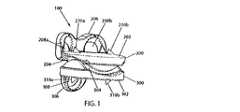
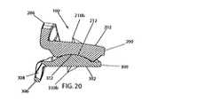
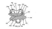
ここで、図1〜図5を参照すると、本発明の人工椎間板インプラント100が、斜視図、正面図、側面図、側断面図、後側断面図でそれぞれ示されている。インプラント100は、第1の(例えば上側)部材200および第2の(例えば下側)部材300を備えており、各部材は、外側に面する椎体接触面202,302を有しているとともに、内側に面する関節面204,304を有している。部材200,300は、図示のように、関節面204,304が互いに嵌め合わされ、かつ椎体接触面202,302が互いに離れるように向いた状態で配置されている。インプラント100が頸部脊椎の椎間板空間内に配置されると、この構成において、椎体接触面202,302が対応の隣接する椎体終板(図示せず)と係合した状態では、インプラント100により、隣り合う椎骨は、後述するように適切な解剖学的動作に従って互いに対して動くことが可能である。 1 to 5, an
部材200,300のうちの少なくとも一方(より好ましくは、両方)は、部材を隣接する椎体に対して固定するための少なくとも1つの特徴(例えば、貫通孔208a,208b,308)を有する少なくとも1つの長期固定構造(例えば、フランジ206,306)を有していることが好ましい。例えば、上側部材200は、上側へ延びかつそれぞれが骨ネジ(図示せず)を受け入れる2つの貫通孔208a,208bを有する前フランジ206を有している。また、例えば、下側部材300は、下側に延びかつ骨ネジ(図示せず)を受け入れる1つの貫通孔308を有する前フランジ306を有している。椎体接触面202,302が対応の隣接する椎体終板(図示せず)と係合した状態で部材200,300が椎間板空間内に配置されると、骨ネジが貫通孔208a,208b,308を介して隣接する椎骨の前面に対して固定することで、部材が椎間板空間から脱落したり或いは椎間板空間内で動いたりすることを防止できる。貫通孔208a,208b,308の孔軸は、図示のように隣接する椎体に向かって曲げられていることが好ましい。 At least one of the
また、部材200,300のうちの少なくとも一方(より好ましくは、両方)は、部材を隣接する椎体に対して(より好ましくは、隣接する椎体終板に対して)固定するための少なくとも1つの短期固定構造(例えば、スパイク210a,210b,310a,310b)を有していることが好ましい。例えば、各部材200,300は、対応する一対の外側に向けられたスパイク210a,210b,310a,310bを有している。椎体接触面202,302が対応の隣接する椎体終板(図示せず)と係合した状態で部材200,300が椎間板空間内に配置されると、スパイク210a,210b,310a,310bが脊柱の長軸に沿って隣接する椎体終板中に圧縮下で埋め込まれ、したがって、部材が椎間板空間から脱落したり或いは椎間板空間内で動いたりすることを防止できる。好ましくは、各スパイク210a,210b,310a,310bは、椎間板空間内へのインプラント100の挿入の容易性を促進するために、図示のようにその後側が椎体接触面202,302に向かって後方へと傾斜しているとともに、部材200,300が椎間板空間から前側(あるいは、それ以外の方向)に抜け出ないようにするために、(図示のように)その前側が椎体接触面202,302に対して垂直になっており、あるいは、その前側が椎体接触面202,302に向かって後方へと傾斜している(図示せず)。 Also, at least one of
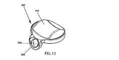
特に、ここで、図6〜図12を参照すると、図1〜図5に示される人工椎間板インプラント100の上側部材200が、斜視図、底面図(長手方向で見上げた図)、側面図、前面図、側断面図、平面図(長手方向で見下した図)、後側断面図でそれぞれ示されている。また、特に、図13〜図19を参照すると、図1〜図5における人工椎間板インプラント100の下側部材300が、斜視図、平面図(長手方向で見下した図)、側面図、正面図、側断面図、底面図(長手方向で見上げた図)、後側断面図でそれぞれ示されている。 In particular, referring now to FIGS. 6-12, the
前述したように、各部材200,300は、長手方向外側に向けられた椎体接触面202,302を有している。各面202,302は、それが位置決め接触される隣接する椎体(図示せず)の終板に適合するように形成されていることが好ましい。例えば、頸部脊椎における椎骨の下側の終板のそれぞれが中心凹部を有することが関連する解剖学的検査によって分かっている限りにおいては、中心凹部に適合するように、面202が湾曲されている(より好ましくは、図示のようにドーム状を成している、あるいは、半円柱状を成している)ことが好ましい。また、例えば、頸部脊椎における椎骨の上側の終板が略平坦であることが関連する解剖学的検査によって分かっている限りにおいては、図示のように面302が平坦であることが好ましい。本発明の範囲から逸脱することなく、隣接する椎体終板に厳密に適合するこれらの形状または他の形状を成すように面202,302を形成することができ或いは動的に形成できることは言うまでもない。 As described above, each of the
また、各椎体接触面202,302は、骨誘導特徴または骨伝導特徴を更に有していることが好ましい。例えば、各面202,302は、多孔質及び/又は粗面であることが好ましい。これは、例えばグリットブラスト、ポーラスコーティング(多孔質被覆)、エッチング、焼成、放電加工、焼結ビーディングを含む技術的に知られた任意の方法によって達成可能である。両方の面202,302にそのような特徴が設けられていることが好ましいが、本発明の範囲から逸脱することなく、一方の面だけがそのような特徴を有していてもよいことは言うまでもない。また、全面がそのように特徴付けられている必要はなく、一部だけ、幾つかの部分だけ、あるいは、面の全てがそのように特徴付けられていてもよく、または、本発明の範囲から逸脱することなく、様々なそのような特徴を有していてもよいことは言うまでもない。 In addition, each vertebral
また、各椎体接触面202,302は、前述し且つこれらの図6〜図19で対応する参照符号により示された長期固定構造および短期固定構造を有していることが好ましい。 Each vertebral
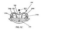
前述したように、上側部材200は、長手方向内側に向けられた関節面204を有している。好ましくは、図示のように、関節面204は、凸状の円弧(図12に参照符号214で示されている)に対して垂直に押しつけられ、かつ当該円弧に沿って延びる凹状の円弧(図10に参照符号212で示されている)によって画成されるサドル面を備えている。図4、図5、図10および図12に最も良く示されるように、関節面204は、凹状の円弧212を形成する断面を一方の面内に有しているとともに、凸状の円弧214を形成する断面を他方の面(前述の面に対して垂直な面)内に有している。凹状の円弧212は、一方の面に対して垂直な軸を中心とする対応する一定の曲率半径を有する。凸状の円弧214は、他方の面に対して垂直な軸を中心とする対応する一定の曲率半径を有している。したがって、関節面204は、半径が一定のサドル形状の関節面を形成している。 As described above, the
この好ましい実施形態においては、図10に示されるように、凹状の円弧212は、前後面に対して垂直な軸を中心とする一定の曲率半径Aを有している。また、この好ましい実施形態においては、図12に示されるように、凸状の円弧214は、横方向の面に対して垂直な軸を中心とする一定の曲率半径Bを有している。半径Aが半径Bよりも短いことが好ましく、半径Aが0.329インチ(0.826センチ)であり、かつ半径Bが0.340インチ(0.864センチ)であることが最も好ましい。しかしながら、本発明は任意の特定の寸法組に限定されず、本発明の幾つかの実施形態においては、半径Aが半径Bと等しく、あるいは、半径Aが半径Bよりも長い。 In this preferred embodiment, as shown in FIG. 10, the
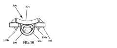
また、前述したように、下側部材300は、長手方向内側に向けられた関節面304を有している。好ましくは、図示のように、関節面304は、凹状の円弧(図19に参照符号314で示されている)に対して垂直に押しつけられ、かつ当該円弧に沿って延びる凸状の円弧(図17に参照符号312で示されている)によって画成されるサドル面を備えている。図4、図5、図17および図19に最も良く示されるように、関節面304は、凸状の円弧312を形成する断面を一方の面内に有しているとともに、凹状の円弧314を形成する断面を他方の面(前述の面に対して垂直な面)内に有している。凸状の円弧312は、一方の面に対して垂直な軸を中心とする対応する一定の曲率半径を有している。凹状の円弧314は、他方の面に対して垂直な軸を中心とする対応する一定の曲率半径を有している。したがって、関節面304も、半径が一定のサドル形状の関節面を形成している。 Further, as described above, the
この好ましい実施形態においては、図17に示されるように、凸状の円弧312は、前後面に対して垂直な軸を中心とする一定の曲率半径Cを有している。また、この好ましい実施形態においては、図19に示されるように、凹状の円弧314は、横方向の面に対して垂直な軸を中心とする一定の曲率半径Dを有している。半径Cが半径Dよりも小さいことが好ましく、半径Cが0.280インチ(0.711センチ)であり、かつ半径Dが0.401インチ(1.119センチ)であることが最も好ましい。しかしながら、本発明は特定の寸法組に限定されず、本発明の幾つかの実施形態においては、半径Cが半径Dと等しく、あるいは、半径Cが半径Dよりも長い。また、幾つかの実施形態においては、半径A、B、CおよびDが等しい寸法からなっている。 In this preferred embodiment, as shown in FIG. 17, the
重要なことには、半径が一定のサドル形状の関節面204,304は、互いに嵌合可能でかつ互いに関節を成すことが可能であるように構成されて寸法付けられており、これにより、(上側および下側部材200,300がそれぞれ椎間板空間内で接触して配置されている)隣接する椎骨は、屈曲、伸長、および横曲げ時に関節を成すことが可能となっている。特に、図1〜図5に最も良く示されるように、本発明の人工椎間板100は、椎体接触面202,302が互いに離れるように方向付けられ、かつ関節面204,304が互いに嵌め合わされることにより凹状の円弧212が凸状の円弧312を受け入れるとともに、凸状の円弧214が凹状の円弧314により受け入れられるように上側部材200および下側部材300を配置することによって組み立てられている。インプラント100のそのような組立中または組立後、上側部材200の椎体接触面202が上椎体(図示せず)の下側終板に対して固定されるとともに、下側部材300の椎体接触面302が下椎体(図示せず)の上側終板に対して固定される。前述したように、部材200,300をこれらの隣接する椎骨に対して固定するためには、部材200,300の好ましい長期固定構造および短期固定構造が役立つことになる。 Importantly, the saddle-shaped articulating
したがって、隣接する椎骨同士の互いに対する動きは、上側部材200と下側部材300との相対的な動きによって許容されることになる。隣接する椎骨が屈曲、伸長、および横曲げ時に関節を成すことが可能であるように構成されて寸法付けられた関節面204,304に関しては、屈曲および伸張時に凸状の円弧312によって規定される円の中心における回転中心(図18にR3で示されている)回りで上側部材200の凹状の円弧(例えば212)が下側部材300の凸状の円弧(例えば312)上で揺動することは、インプラント100が組み立てられて埋め込まれた際の上側部材200および下側部材300の前述した幾何学的構造および位置合わせから理解される。この回転中心R3は関節面304よりも下側にある。横曲げ時に凸状の円弧214によって画成される円の中心における回転中心(図12にR2で示されている)回りで下側部材300の凹状の円弧(例えば314)が上側部材200の凸状の円弧(例えば214)上で揺動することは、上側部材200および下側部材300の前述した幾何学的構造および位置合わせから更に理解される。この回転中心R2は関節面204よりも上側にある。これらの関節結合中、部材200,300は、一定の相対的な伸延位置に維持されている。すなわち、部材200,300は、互いに離れる方向に移動しない(例えば、互いに反対の軸方向に(例えば脊椎の長軸に沿って)移動しない)。したがって、本発明は、動きの1つの形態(横曲げ)において関節面よりも上側に回転中心を有し、かつ動きの他の形態(屈曲/伸張)において関節面よりも下側に回転中心を有するとともに、頸部脊椎における自然の椎間接合部とのこれらの関連において矛盾しない一対の関節面204,304を提供するものである。関節面204,304は、屈曲/伸張および横曲げを受けることができる対応する角度範囲が頸部脊椎内でのそのような動きにおける通常の対応する生理学的範囲と等しくなる或いは当該生理学的範囲よりも大きくなるように寸法付けられて構成されていることが好ましい。本発明は特定の寸法に限定されないが、好ましい実施形態は、凸状の円弧312および凸状の円弧214に関して以下の曲率半径を有している。すなわち、C=0.280インチであり、B=0.340インチである。そのような好ましい曲率半径により、好ましい実施形態では、±7.5°(全体で15°)の屈曲/伸張範囲および±7.5°(全体で15°)の横曲げ範囲が得られる。 Therefore, the movement of adjacent vertebrae relative to each other is allowed by the relative movement of the
凹状の円弧212が凸状の円弧312の一定の曲率半径Cよりも大きい一定の曲率半径Aを有し(後述する理由により)、かつ凹状の円弧314が凸状の円弧214の一定の曲率半径Bよりも大きい一定の曲率半径Dを有した(後述する理由により)状態で好ましい実施形態が示されているが、前述した機能も他の相対的な半径サイズを使用して得られることは言うまでもない。例えば、凹状の円弧212の一定の曲率半径Aが凸状の円弧312の一定の曲率半径Cと一致しない(例えば小さい)或いは一致する(すなわち等しい)場合、及び/又は、凹状の円弧314の一定の曲率半径Dが凸状の円弧214の一定の曲率半径Bと一致しない(例えば小さい)或いは一致する(すなわち等しい)場合でも、屈曲、伸張、および横曲げは可能である。 The
前述したように、上記屈曲、伸張、および横曲げ動作に加えて、隣接する椎骨は、人工椎間板インプラント100により、所定の角度範囲にわたって、その範囲内で反対の(あるいは、互いに離れるように向けられた)方向に(例えば長軸に沿って)動くことなく、互いに対して軸方向に(例えば脊柱の長軸を中心に)回転可能であることが好ましい。したがって、関節面204,304は、そのような動きを許容するように構成されて寸法付けられていることが好ましい。再び図1〜図5を参照すると、一例として好ましい構成が示されている。この構成において、凹状の円弧212の一定の曲率半径Aは、凸状の円弧312の一定の曲率半径Cよりも大きく、また、凹状の円弧314の一定の曲率半径Dは、凸状の円弧214の一定の曲率半径Bよりも大きい。異なる半径によって得られる空間により、関節面204,304の縁部において、椎体接触面202,302を反対の(あるいは、互いに離れるように向けられた)方向に(例えば長軸に沿って)移動させることなく、上側部材200および下側部材300が所定の範囲にわたって互いに対して(例えば長軸を中心に)軸方向に回転できることは、上側部材200および下側部材300の前述した幾何学的構造および位置合わせから理解される。軸方向の回転がその範囲を超えると、凹状の円弧212,314が互いに平行になる位置へと移動するため、関節面204,304が互いに干渉し、また、凹状の円弧212,314がそれらの反対に向けられた傾斜面に対して乗り上がるため、連続する軸方向回転と共に椎体接触面202,302間の距離が増大することになる。したがって、脊柱の長軸を中心とする隣接する椎骨の通常の生理学的な軸方向回転動作を、異常な即時の軸方向反対側の(あるいは、互いに離れるように向けられた)移動を生じさせることなく、所定の角度範囲にわたって許容するように、また、そのような軸方向反対側の(あるいは、互いに離れるように向けられた)移動を通常の生理学的条件下でそれが起こるべき時にすなわちその角度範囲外で許容するように、本発明に従って関節面204,304を形成することができる。本発明は任意の特定の寸法に限定されないが、好ましい実施形態は以下の曲率半径を有する。すなわち、A=0.329インチであり、B=0.340インチであり、C=0.280インチであり、D=0.401インチである。そのような好ましい曲率半径により、好ましい実施形態では、関節面の反対方向の移動が生じる前に、±3°(全体で6°)の長軸回転範囲が得られる。 As described above, in addition to the bending, stretching, and lateral bending operations, adjacent vertebrae are directed opposite (or separated from) each other within a predetermined angular range by the
なお、好ましい実施形態において、また、凹状の円弧212の一定の曲率半径Aが凸状の円弧312の一定の曲率半径Cよりも大きく、かつ凹状の円弧314の一定の曲率半径Dが凸状の円弧214の一定の曲率半径Bよりも大きい他の好ましい実施形態において、関節面204,304は、隣接する椎骨間での通常の生理学的な関節動作の範囲にわたって二地点間接触を維持している。これが図4、図5、図20および図21に示されている。特に、屈曲、伸張、横曲げ、および軸方向回転にわたって関節面204,304が図4および図5の状態にある時に互いに二地点間接触することは、上側部材200および下側部材300の前述した幾何学的構造および位置合わせから理解される。伸張および横曲げ状態にそれぞれあるインプラント100を示すために、また、この好ましい特徴を示すために、図20および図21が与えられている。 In the preferred embodiment, the constant radius of curvature A of the
なお、関節面204,304の曲率半径寸法が、隣接する椎骨の通常の生理学的な屈曲動作、伸張動作、横曲げ動作、および軸方向回転動作を許容する関節面204,304の構成および寸法付けに関連していることに加えて、特に選択された曲率半径に関しては、表面積の大きさも関連している。特に、頸部脊椎の通常の生理学的範囲内にある相対的な角度範囲を与えるためには、前述したように選択された曲率半径を適切にしなければならないだけでなく、それに応じて、選択された曲率半径が与えられると、試みられた関節結合の通常の生理学的範囲の限界に達する前に、サドル面の縁部(特に、凹状の円弧(例えば212,314)の縁部)が周囲の任意の解剖学的構造または対向する部材(200または300)の他の部分にぶつからないようにする大きさにサドル面の表面積を設定しなければならない。図示のように、上側部材200および下側部材300の内側に向いた面の一方または両方は、適切な表面積の大きさを確保してそのような干渉を防止するため、その関節面(204または304)を形成する前に内側に先細っていてもよい。本発明は任意の特定の表面積の大きさに限定されないが、図示の好ましい実施形態は、0.146平方インチに等しい関節面204の表面積および0.153平方インチに等しい関節面304の表面積を有している。 It should be noted that the radius of curvature of the articulating
更に好ましくは、関節面204,304は、滑らかな軸受面を形成するように研磨されたコバルトクロムによって形成されている。関節面204,304は、好ましくはコバルトクロムによって形成されているが、これに加えて或いはこれに代えて、本発明の範囲から逸脱することなく、例えばステンレススチール及び/又はチタン等の他の金属または例えばポリエチレン及び/又はセラミック材料(例えばアルミナおよびジルコニア)等の非金属あるいは他の任意の適当な材料によって形成されていてもよいことは言うまでもない。 More preferably, the articulating
なお、本発明は、頸部脊椎で使用するための人工椎間板インプラントとして図示されて説明されているが、本発明の人工椎間板インプラントは、本発明の範囲から逸脱することなく、脊椎の任意の他の部分での使用にも適合し得る。 It should be noted that although the present invention is illustrated and described as an artificial disc implant for use in the cervical spine, the artificial disc implant of the present invention may be used in any other spine without departing from the scope of the present invention. It can also be adapted for use in these parts.
ここに示されて詳細に開示された脊椎の頸部椎間板接合のための特定のプロテーゼはそれぞれ、目的を十分に達成できるとともに、前述した利点を与えることができるが、これらのバリエーションは、本発明の現在において好ましい実施形態の単なる例示であり、ここに示された構造または形状の内容から推測されるように本発明の範囲に限定を加えるものではないことは言うまでもない。 Each of the specific prostheses for spinal cervical intervertebral joints shown and disclosed in detail herein can fully accomplish the objectives and provide the aforementioned advantages, although these variations are It is to be understood that the presently preferred embodiments are merely exemplary, and are not intended to limit the scope of the invention, as may be inferred from the structure or shape shown herein.
Claims (10)
Translated fromJapanese上椎体の終板に当接するための上側表面と下側関節面とを有し、前記下側関節面の全体は単一のサドル面であり、脊柱の前後の面に対して垂直な第1の軸を中心とする一定の曲率半径Aを有する凹状の円弧と、脊柱の横方向の面に対して垂直な第1の軸を中心とする一定の曲率半径Bを有する凸状の円弧とによって前記サドル面が画成される第1の部材と、
下椎体の終板に当接するための下側表面と上側関節面とを有し、前記上側関節面の全体は単一のサドル面であり、脊柱の前後の面に対して垂直な第2の軸を中心とする一定の曲率半径Cを有する凸状の円弧と、脊柱の横方向の面に対して垂直な第2の軸を中心とする一定の曲率半径Dを有する凹状の円弧とによって前記サドル面が画成され、前記一定の曲率半径Aは前記一定の曲率半径Cよりも大きく、且つ前記一定の曲率半径Bは前記一定の曲率半径Dよりも小さい第2の部材と、
を備え、
前記第1の部材の前記サドル面および前記第2の部材の前記サドル面は、互いに嵌合可能であるとともに、脊柱の前後の面内での屈曲/伸張時および脊柱の横方向の面内での横曲げ時においてそれぞれ互いに対して関節を成すことが可能である、関節接合インプラント。An articulating implant for use in the spinal column,
An upper surface for contacting the endplate of the upper vertebral body and a lower articular surface, wherein the entire lower articular surface is a single saddle surface and is perpendicular to the anterior and posterior surfaces of the spinal column. A concave arc having a constant radius of curvature A centered on one axis, and a convex arc having a constant radius of curvature B centered on a first axis perpendicular to the transverse plane of the spine; A first member defining the saddle surface by:
A lower surface for abutting the endplate of the inferior vertebral body and an upper articulating surface, the entire upper articulating surface being a single saddle surface, and a second perpendicular to the anterior and posterior surfaces of the spinal column A convex arc having a constant radius of curvature C centered on the axis and a concave arc having a constant radius of curvature D centered on a second axis perpendicular to the transverse plane of the spinal column. A saddle surface is defined, the constant radius of curvature A is greater than the constant radius of curvature C, and the constant radius of curvature B is smaller than the constant radius of curvature D;
With
The saddle surface of the first member and the saddle surface of the second member are matable with each other, and when flexing / extending in the front and back planes of the spine and in the lateral plane of the spine Articulating implants that can each be articulated with respect to each other during lateral bending.
Applications Claiming Priority (2)
| Application Number | Priority Date | Filing Date | Title |
|---|---|---|---|
| US10/382,702 | 2003-03-06 | ||
| US10/382,702US6908484B2 (en) | 2003-03-06 | 2003-03-06 | Cervical disc replacement |
Related Parent Applications (1)
| Application Number | Title | Priority Date | Filing Date |
|---|---|---|---|
| JP2006508715ADivisionJP4701162B2 (en) | 2003-03-06 | 2004-02-11 | Cervical disc replacement |
Publications (2)
| Publication Number | Publication Date |
|---|---|
| JP2010194330Atrue JP2010194330A (en) | 2010-09-09 |
| JP5209661B2 JP5209661B2 (en) | 2013-06-12 |
Family
ID=32926947
Family Applications (5)
| Application Number | Title | Priority Date | Filing Date |
|---|---|---|---|
| JP2006508715AExpired - Fee RelatedJP4701162B2 (en) | 2003-03-06 | 2004-02-11 | Cervical disc replacement |
| JP2010084935AExpired - Fee RelatedJP5209661B2 (en) | 2003-03-06 | 2010-04-01 | Cervical disc replacement |
| JP2010093684AExpired - Fee RelatedJP5346316B2 (en) | 2003-03-06 | 2010-04-15 | Intervertebral disk replacement device |
| JP2012261106ACeasedJP2013056207A (en) | 2003-03-06 | 2012-11-29 | Drill assembly |
| JP2014047540APendingJP2014176647A (en) | 2003-03-06 | 2014-03-11 | Artificial intervertebral disk and insert plate |
Family Applications Before (1)
| Application Number | Title | Priority Date | Filing Date |
|---|---|---|---|
| JP2006508715AExpired - Fee RelatedJP4701162B2 (en) | 2003-03-06 | 2004-02-11 | Cervical disc replacement |
Family Applications After (3)
| Application Number | Title | Priority Date | Filing Date |
|---|---|---|---|
| JP2010093684AExpired - Fee RelatedJP5346316B2 (en) | 2003-03-06 | 2010-04-15 | Intervertebral disk replacement device |
| JP2012261106ACeasedJP2013056207A (en) | 2003-03-06 | 2012-11-29 | Drill assembly |
| JP2014047540APendingJP2014176647A (en) | 2003-03-06 | 2014-03-11 | Artificial intervertebral disk and insert plate |
Country Status (6)
| Country | Link |
|---|---|
| US (30) | US6908484B2 (en) |
| EP (1) | EP1599150A4 (en) |
| JP (5) | JP4701162B2 (en) |
| AU (1) | AU2010201667B2 (en) |
| CA (3) | CA2518068C (en) |
| WO (1) | WO2004080349A1 (en) |
Cited By (1)
| Publication number | Priority date | Publication date | Assignee | Title |
|---|---|---|---|---|
| JP2015504772A (en)* | 2012-01-31 | 2015-02-16 | ブラックストーン メディカル,インコーポレイテッド | Intervertebral disc prosthesis and method |
Families Citing this family (527)
| Publication number | Priority date | Publication date | Assignee | Title |
|---|---|---|---|---|
| US7494507B2 (en)* | 2000-01-30 | 2009-02-24 | Diamicron, Inc. | Articulating diamond-surfaced spinal implants |
| US5774670A (en)* | 1995-10-06 | 1998-06-30 | Netscape Communications Corporation | Persistent client state in a hypertext transfer protocol based client-server system |
| US6936071B1 (en) | 1999-07-02 | 2005-08-30 | Spine Solutions, Inc. | Intervertebral implant |
| US8540704B2 (en)* | 1999-07-14 | 2013-09-24 | Cardiofocus, Inc. | Guided cardiac ablation catheters |
| EP1792586B1 (en) | 1999-09-14 | 2012-12-26 | Spine Solutions Inc. | Insert instrument for an implant between vertebrae |
| US6730127B2 (en)* | 2000-07-10 | 2004-05-04 | Gary K. Michelson | Flanged interbody spinal fusion implants |
| US7833250B2 (en) | 2004-11-10 | 2010-11-16 | Jackson Roger P | Polyaxial bone screw with helically wound capture connection |
| US7169182B2 (en) | 2001-07-16 | 2007-01-30 | Spinecore, Inc. | Implanting an artificial intervertebral disc |
| US6673113B2 (en) | 2001-10-18 | 2004-01-06 | Spinecore, Inc. | Intervertebral spacer device having arch shaped spring elements |
| US7695521B2 (en) | 2001-05-01 | 2010-04-13 | Amedica Corporation | Hip prosthesis with monoblock ceramic acetabular cup |
| US20050177238A1 (en)* | 2001-05-01 | 2005-08-11 | Khandkar Ashok C. | Radiolucent bone graft |
| EP2055267B1 (en)* | 2001-05-01 | 2013-04-17 | Amedica Corporation | Radiolucent bone graft |
| US7776085B2 (en)* | 2001-05-01 | 2010-08-17 | Amedica Corporation | Knee prosthesis with ceramic tibial component |
| US10729469B2 (en) | 2006-01-09 | 2020-08-04 | Roger P. Jackson | Flexible spinal stabilization assembly with spacer having off-axis core member |
| US8292926B2 (en) | 2005-09-30 | 2012-10-23 | Jackson Roger P | Dynamic stabilization connecting member with elastic core and outer sleeve |
| US10258382B2 (en) | 2007-01-18 | 2019-04-16 | Roger P. Jackson | Rod-cord dynamic connection assemblies with slidable bone anchor attachment members along the cord |
| US7862587B2 (en) | 2004-02-27 | 2011-01-04 | Jackson Roger P | Dynamic stabilization assemblies, tool set and method |
| US8353932B2 (en) | 2005-09-30 | 2013-01-15 | Jackson Roger P | Polyaxial bone anchor assembly with one-piece closure, pressure insert and plastic elongate member |
| US20070173858A1 (en)* | 2001-06-14 | 2007-07-26 | Alexandria Research Technologies, Llc | Apparatus and Method for Sculpting the Surface of a Joint |
| EP1408874B1 (en)* | 2001-06-14 | 2012-08-08 | Amedica Corporation | Metal-ceramic composite articulation |
| US7713302B2 (en) | 2001-10-01 | 2010-05-11 | Spinecore, Inc. | Intervertebral spacer device utilizing a spirally slotted belleville washer having radially spaced concentric grooves |
| US7771477B2 (en) | 2001-10-01 | 2010-08-10 | Spinecore, Inc. | Intervertebral spacer device utilizing a belleville washer having radially spaced concentric grooves |
| AU2003215099A1 (en)* | 2002-02-07 | 2003-09-02 | Ebi, L.P. | Anterior spinal implant |
| AR038680A1 (en) | 2002-02-19 | 2005-01-26 | Synthes Ag | INTERVERTEBRAL IMPLANT |
| US20090182341A1 (en)* | 2002-03-12 | 2009-07-16 | Cervitech, Inc. | Instrument set for fitting an intervertebral jont prosthesis |
| EP1344493B1 (en)* | 2002-03-12 | 2009-09-02 | Cervitech, Inc. | Instument set for insertion of intervertebral prostheses |
| US7527629B2 (en)* | 2002-03-12 | 2009-05-05 | Cervitech, Inc. | Instrument set for fitting an intervertebral joint prosthesis |
| US8038713B2 (en) | 2002-04-23 | 2011-10-18 | Spinecore, Inc. | Two-component artificial disc replacements |
| US20080027548A9 (en) | 2002-04-12 | 2008-01-31 | Ferree Bret A | Spacerless artificial disc replacements |
| US6706068B2 (en)* | 2002-04-23 | 2004-03-16 | Bret A. Ferree | Artificial disc replacements with natural kinematics |
| US8388684B2 (en) | 2002-05-23 | 2013-03-05 | Pioneer Signal Technology, Inc. | Artificial disc device |
| US8876868B2 (en) | 2002-09-06 | 2014-11-04 | Roger P. Jackson | Helical guide and advancement flange with radially loaded lip |
| WO2006052796A2 (en) | 2004-11-10 | 2006-05-18 | Jackson Roger P | Helical guide and advancement flange with break-off extensions |
| AU2003226586A1 (en) | 2002-09-19 | 2004-04-08 | Malan De Villiers | Intervertebral prosthesis |
| JP4654125B2 (en)* | 2002-10-29 | 2011-03-16 | スパインコア,インコーポレイテッド | Instruments, methods, and functions for use in implanting an artificial disc |
| US7204852B2 (en) | 2002-12-13 | 2007-04-17 | Spine Solutions, Inc. | Intervertebral implant, insertion tool and method of inserting same |
| AU2003297195A1 (en)* | 2002-12-17 | 2004-07-22 | Amedica Corporation | Total disc implant |
| GB0301085D0 (en)* | 2003-01-17 | 2003-02-19 | Krishna Manoj | Articulating spinal disc prosthesis |
| ZA200506029B (en)* | 2003-01-31 | 2006-10-25 | Spinalmotion Inc | Spinal Midline Indicator |
| WO2004066884A1 (en) | 2003-01-31 | 2004-08-12 | Spinalmotion, Inc. | Intervertebral prosthesis placement instrument |
| CA2515247C (en) | 2003-02-06 | 2010-10-05 | Synthes (U.S.A.) | Intervertebral implant |
| US7235101B2 (en) | 2003-09-15 | 2007-06-26 | Warsaw Orthopedic, Inc. | Revisable prosthetic device |
| US6908484B2 (en)* | 2003-03-06 | 2005-06-21 | Spinecore, Inc. | Cervical disc replacement |
| AU2004220634B2 (en)* | 2003-03-06 | 2009-09-17 | Spinecore, Inc. | Instrumentation and methods for use in implanting a cervical disc replacement device |
| US7819903B2 (en) | 2003-03-31 | 2010-10-26 | Depuy Spine, Inc. | Spinal fixation plate |
| BRPI0409091A (en)* | 2003-04-07 | 2006-04-11 | Cervitech Inc | intervertebral joint prosthesis for the cervical spine |
| US8012212B2 (en)* | 2003-04-07 | 2011-09-06 | Nuvasive, Inc. | Cervical intervertebral disk prosthesis |
| US20070016200A1 (en)* | 2003-04-09 | 2007-01-18 | Jackson Roger P | Dynamic stabilization medical implant assemblies and methods |
| US7621918B2 (en) | 2004-11-23 | 2009-11-24 | Jackson Roger P | Spinal fixation tool set and method |
| US8540753B2 (en) | 2003-04-09 | 2013-09-24 | Roger P. Jackson | Polyaxial bone screw with uploaded threaded shank and method of assembly and use |
| US7491204B2 (en)* | 2003-04-28 | 2009-02-17 | Spine Solutions, Inc. | Instruments and method for preparing an intervertebral space for receiving an artificial disc implant |
| US7377923B2 (en) | 2003-05-22 | 2008-05-27 | Alphatec Spine, Inc. | Variable angle spinal screw assembly |
| US10052211B2 (en) | 2003-05-27 | 2018-08-21 | Simplify Medical Pty Ltd. | Prosthetic disc for intervertebral insertion |
| US7442211B2 (en) | 2003-05-27 | 2008-10-28 | Spinalmotion, Inc. | Intervertebral prosthetic disc |
| US7575599B2 (en)* | 2004-07-30 | 2009-08-18 | Spinalmotion, Inc. | Intervertebral prosthetic disc with metallic core |
| US8366753B2 (en) | 2003-06-18 | 2013-02-05 | Jackson Roger P | Polyaxial bone screw assembly with fixed retaining structure |
| US7776067B2 (en) | 2005-05-27 | 2010-08-17 | Jackson Roger P | Polyaxial bone screw with shank articulation pressure insert and method |
| US7967850B2 (en) | 2003-06-18 | 2011-06-28 | Jackson Roger P | Polyaxial bone anchor with helical capture connection, insert and dual locking assembly |
| US8092500B2 (en) | 2007-05-01 | 2012-01-10 | Jackson Roger P | Dynamic stabilization connecting member with floating core, compression spacer and over-mold |
| US7766915B2 (en) | 2004-02-27 | 2010-08-03 | Jackson Roger P | Dynamic fixation assemblies with inner core and outer coil-like member |
| US8926670B2 (en) | 2003-06-18 | 2015-01-06 | Roger P. Jackson | Polyaxial bone screw assembly |
| US7803162B2 (en)* | 2003-07-21 | 2010-09-28 | Spine Solutions, Inc. | Instruments and method for inserting an intervertebral implant |
| FR2858546B1 (en)* | 2003-08-04 | 2006-04-28 | Spine Next Sa | INTERVERTEBRAL DISC PROSTHESIS |
| US9254137B2 (en)* | 2003-08-29 | 2016-02-09 | Lanterna Medical Technologies Ltd | Facet implant |
| US7938858B2 (en)* | 2003-09-15 | 2011-05-10 | Warsaw Orthopedic, Inc. | Spinal implant system |
| WO2005037135A2 (en)* | 2003-10-14 | 2005-04-28 | The University Of Iowa Research Foundation | Ankle prosthesis and method for implanting ankle prosthesis |
| DE602004006709T2 (en)* | 2003-11-07 | 2008-02-07 | Impliant Ltd. | SPINE GRAFT |
| US7588590B2 (en) | 2003-12-10 | 2009-09-15 | Facet Solutions, Inc | Spinal facet implant with spherical implant apposition surface and bone bed and methods of use |
| US11419642B2 (en) | 2003-12-16 | 2022-08-23 | Medos International Sarl | Percutaneous access devices and bone anchor assemblies |
| US7527638B2 (en) | 2003-12-16 | 2009-05-05 | Depuy Spine, Inc. | Methods and devices for minimally invasive spinal fixation element placement |
| US7179261B2 (en) | 2003-12-16 | 2007-02-20 | Depuy Spine, Inc. | Percutaneous access devices and bone anchor assemblies |
| US8123757B2 (en) | 2003-12-31 | 2012-02-28 | Depuy Spine, Inc. | Inserter instrument and implant clip |
| US7771479B2 (en) | 2004-01-09 | 2010-08-10 | Warsaw Orthopedic, Inc. | Dual articulating spinal device and method |
| US7556651B2 (en)* | 2004-01-09 | 2009-07-07 | Warsaw Orthopedic, Inc. | Posterior spinal device and method |
| US20050171610A1 (en)* | 2004-01-09 | 2005-08-04 | Sdgi Holdings, Inc. | Mobile bearing spinal device and method |
| US20050171608A1 (en) | 2004-01-09 | 2005-08-04 | Sdgi Holdings, Inc. | Centrally articulating spinal device and method |
| US7901459B2 (en)* | 2004-01-09 | 2011-03-08 | Warsaw Orthopedic, Inc. | Split spinal device and method |
| US20050154467A1 (en)* | 2004-01-09 | 2005-07-14 | Sdgi Holdings, Inc. | Interconnected spinal device and method |
| US7875077B2 (en)* | 2004-01-09 | 2011-01-25 | Warsaw Orthopedic, Inc. | Support structure device and method |
| GB2410189A (en)* | 2004-01-23 | 2005-07-27 | Corin Ltd | Intervertebral disc prosthesis |
| US20050165407A1 (en)* | 2004-01-23 | 2005-07-28 | Diaz Robert L. | Disk arthroplasty instrumentation and implants |
| US20050165487A1 (en) | 2004-01-28 | 2005-07-28 | Muhanna Nabil L. | Artificial intervertebral disc |
| US7846183B2 (en) | 2004-02-06 | 2010-12-07 | Spinal Elements, Inc. | Vertebral facet joint prosthesis and method of fixation |
| US8562649B2 (en) | 2004-02-17 | 2013-10-22 | Gmedelaware 2 Llc | System and method for multiple level facet joint arthroplasty and fusion |
| US8333789B2 (en) | 2007-01-10 | 2012-12-18 | Gmedelaware 2 Llc | Facet joint replacement |
| US11241261B2 (en) | 2005-09-30 | 2022-02-08 | Roger P Jackson | Apparatus and method for soft spinal stabilization using a tensionable cord and releasable end structure |
| JP2007525274A (en) | 2004-02-27 | 2007-09-06 | ロジャー・ピー・ジャクソン | Orthopedic implant rod reduction instrument set and method |
| US8152810B2 (en) | 2004-11-23 | 2012-04-10 | Jackson Roger P | Spinal fixation tool set and method |
| US7160300B2 (en) | 2004-02-27 | 2007-01-09 | Jackson Roger P | Orthopedic implant rod reduction tool set and method |
| US7383164B2 (en)* | 2004-03-05 | 2008-06-03 | Depuy Products, Inc. | System and method for designing a physiometric implant system |
| US7282065B2 (en)* | 2004-04-09 | 2007-10-16 | X-Spine Systems, Inc. | Disk augmentation system and method |
| US7963981B2 (en)* | 2004-04-19 | 2011-06-21 | Globus Medical, Inc. | Bone fixation plate |
| US8236034B2 (en) | 2004-04-19 | 2012-08-07 | Globus Medical, Inc. | Bone fixation plate |
| US8535379B2 (en) | 2006-04-04 | 2013-09-17 | Nathan C. Moskowitz | Artificial cervical and lumbar discs, disc plate insertion gun for performing sequential single plate intervertebral implantation enabling symmetric bi-disc plate alignment for interplate mobile core placement |
| US7854766B2 (en) | 2004-05-13 | 2010-12-21 | Moskowitz Nathan C | Artificial total lumbar disc for unilateral safe and simple posterior placement in the lumbar spine, and removable bifunctional screw which drives vertical sliding expansile plate expansion, and interplate widening, and angled traction spikes |
| US11806244B2 (en) | 2004-05-13 | 2023-11-07 | Moskowitz Family Llc | Artificial cervical and lumbar disc system |
| WO2005117725A2 (en)* | 2004-05-27 | 2005-12-15 | Depuy Spine, Inc. | Tri-joint implant |
| US7507242B2 (en) | 2004-06-02 | 2009-03-24 | Facet Solutions | Surgical measurement and resection framework |
| US9504583B2 (en) | 2004-06-10 | 2016-11-29 | Spinal Elements, Inc. | Implant and method for facet immobilization |
| US9237958B2 (en)* | 2004-06-30 | 2016-01-19 | Synergy Disc Replacement Inc. | Joint prostheses |
| MXPA06014714A (en)* | 2004-06-30 | 2007-06-22 | Synergy Disc Replacement Inc | Artificial spinal disc. |
| US8172904B2 (en)* | 2004-06-30 | 2012-05-08 | Synergy Disc Replacement, Inc. | Artificial spinal disc |
| US8454699B2 (en)* | 2004-06-30 | 2013-06-04 | Synergy Disc Replacement, Inc | Systems and methods for vertebral disc replacement |
| US7205177B2 (en)* | 2004-07-01 | 2007-04-17 | Interuniversitair Microelektronica Centrum (Imec) | Methods of bonding two semiconductor devices |
| US20060020342A1 (en)* | 2004-07-21 | 2006-01-26 | Ferree Bret A | Facet-preserving artificial disc replacements |
| EP1623685A1 (en)* | 2004-08-06 | 2006-02-08 | WALDEMAR LINK GmbH & Co. KG | Hip prosthesis with stem for implantation into the femur |
| US7585326B2 (en) | 2004-08-06 | 2009-09-08 | Spinalmotion, Inc. | Methods and apparatus for intervertebral disc prosthesis insertion |
| US20060036327A1 (en)* | 2004-08-11 | 2006-02-16 | Albert Enayati | Prosthetic intervertebral disc implant |
| DE102004043996B4 (en)* | 2004-09-08 | 2008-04-17 | Aesculap Ag & Co. Kg | Surgical instrument and implant system |
| US20060052870A1 (en)* | 2004-09-09 | 2006-03-09 | Ferree Bret A | Methods and apparatus to prevent movement through artificial disc replacements |
| US7651502B2 (en) | 2004-09-24 | 2010-01-26 | Jackson Roger P | Spinal fixation tool set and method for rod reduction and fastener insertion |
| US9763668B2 (en) | 2004-10-08 | 2017-09-19 | Covidien Lp | Endoscopic surgical clip applier |
| EP2641548B1 (en) | 2004-10-08 | 2015-08-19 | Covidien LP | Endoscopic surgical clip applier |
| CA2809110A1 (en) | 2004-10-08 | 2006-04-20 | Tyco Healthcare Group Lp | Apparatus for applying surgical clips |
| US20060085076A1 (en)* | 2004-10-15 | 2006-04-20 | Manoj Krishna | Posterior spinal arthroplasty-development of a new posteriorly inserted artificial disc and an artificial facet joint |
| US20060085077A1 (en)* | 2004-10-18 | 2006-04-20 | Ebi, L.P. | Intervertebral implant and associated method |
| WO2006042485A1 (en)* | 2004-10-18 | 2006-04-27 | Buettner-Janz Karin | Intervertebral disk endoprosthesis for lumbar and cervical spine, which corresponds to the physiology of movement |
| US8721722B2 (en)* | 2004-10-18 | 2014-05-13 | Ebi, Llc | Intervertebral implant and associated method |
| USD598105S1 (en) | 2004-10-21 | 2009-08-11 | Disc Motion Technologies, Inc. | Convex intervertebral disc prosthesis |
| USD597674S1 (en) | 2004-10-21 | 2009-08-04 | Disc Motion Technologies, Inc. | Concave intervertebral disc prosthesis |
| US20060265074A1 (en)* | 2004-10-21 | 2006-11-23 | Manoj Krishna | Posterior spinal arthroplasty-development of a new posteriorly inserted artificial disc, a new anteriorly inserted artifical disc and an artificial facet joint |
| US7566346B2 (en)* | 2004-10-29 | 2009-07-28 | X-Spine Systems, Inc. | Prosthetic implant and method |
| US8926672B2 (en) | 2004-11-10 | 2015-01-06 | Roger P. Jackson | Splay control closure for open bone anchor |
| US20060111780A1 (en)* | 2004-11-22 | 2006-05-25 | Orthopedic Development Corporation | Minimally invasive facet joint hemi-arthroplasty |
| EP1835868A2 (en) | 2004-11-22 | 2007-09-26 | Orthopedic Development Corporation | Implant device used in mimimally invasive facet joint hemi-arthroplasty |
| US8444681B2 (en) | 2009-06-15 | 2013-05-21 | Roger P. Jackson | Polyaxial bone anchor with pop-on shank, friction fit retainer and winged insert |
| US7887589B2 (en)* | 2004-11-23 | 2011-02-15 | Glenn Bradley J | Minimally invasive spinal disc stabilizer and insertion tool |
| US9168069B2 (en) | 2009-06-15 | 2015-10-27 | Roger P. Jackson | Polyaxial bone anchor with pop-on shank and winged insert with lower skirt for engaging a friction fit retainer |
| US9980753B2 (en) | 2009-06-15 | 2018-05-29 | Roger P Jackson | pivotal anchor with snap-in-place insert having rotation blocking extensions |
| US9216041B2 (en) | 2009-06-15 | 2015-12-22 | Roger P. Jackson | Spinal connecting members with tensioned cords and rigid sleeves for engaging compression inserts |
| WO2006057837A1 (en) | 2004-11-23 | 2006-06-01 | Jackson Roger P | Spinal fixation tool attachment structure |
| WO2006058221A2 (en) | 2004-11-24 | 2006-06-01 | Abdou Samy M | Devices and methods for inter-vertebral orthopedic device placement |
| US8029540B2 (en) | 2005-05-10 | 2011-10-04 | Kyphon Sarl | Inter-cervical facet implant with implantation tool |
| US7776090B2 (en)* | 2004-12-13 | 2010-08-17 | Warsaw Orthopedic, Inc. | Inter-cervical facet implant and method |
| US20060149372A1 (en)* | 2004-12-17 | 2006-07-06 | Paxson Robert D | Artificial spinal disc |
| US20060155284A1 (en)* | 2005-01-07 | 2006-07-13 | Depuy Spine Sarl | Occipital plate and guide systems |
| EP1681039A1 (en)* | 2005-01-17 | 2006-07-19 | Cervitech, Inc. | Pair of intervertebral implants |
| US8083797B2 (en) | 2005-02-04 | 2011-12-27 | Spinalmotion, Inc. | Intervertebral prosthetic disc with shock absorption |
| US10076361B2 (en) | 2005-02-22 | 2018-09-18 | Roger P. Jackson | Polyaxial bone screw with spherical capture, compression and alignment and retention structures |
| US7901437B2 (en) | 2007-01-26 | 2011-03-08 | Jackson Roger P | Dynamic stabilization member with molded connection |
| AU2012211502B2 (en)* | 2005-03-17 | 2014-09-18 | Spinal Elements, Inc. | Implant and method for treating a spine |
| US20060235403A1 (en)* | 2005-03-17 | 2006-10-19 | Jason Blain | Flanged interbody fusion device with locking plate |
| WO2006109132A1 (en)* | 2005-04-12 | 2006-10-19 | Malan De Villiers | Spinal fusion device |
| GB0508678D0 (en) | 2005-04-28 | 2005-06-08 | Cope Aiden | Motion segment intervertebral disc prosthesis |
| AU2006242416A1 (en)* | 2005-05-02 | 2006-11-09 | Seaspine, Inc. | Motion restoring intervertebral device |
| US7799083B2 (en)* | 2005-05-02 | 2010-09-21 | Seaspine, Inc. | Prosthesis for restoring motion in an appendage or spinal joint and an intervertebral spacer |
| US8777959B2 (en) | 2005-05-27 | 2014-07-15 | Spinecore, Inc. | Intervertebral disc and insertion methods therefor |
| US8177823B2 (en) | 2005-06-30 | 2012-05-15 | Depuy Spine Sarl | Orthopedic clamping hook assembly |
| JP4341594B2 (en)* | 2005-06-30 | 2009-10-07 | セイコーエプソン株式会社 | Program for causing computer to execute information processing apparatus and power control method |
| US20070021837A1 (en)* | 2005-07-20 | 2007-01-25 | Ashman Richard B | Stabilizing augment for prosthetic disc |
| US8105368B2 (en) | 2005-09-30 | 2012-01-31 | Jackson Roger P | Dynamic stabilization connecting member with slitted core and outer sleeve |
| FR2894130B1 (en)* | 2005-12-05 | 2012-07-13 | Spineart Sa | CAGES OF CONTENTION AND INTERSOMATIC FUSION OF VERTEBRATES |
| US7887595B1 (en)* | 2005-12-05 | 2011-02-15 | Nuvasive, Inc. | Methods and apparatus for spinal fusion |
| NZ568985A (en) | 2005-12-08 | 2010-11-26 | Fbcdevice Aps | Disc implant |
| US20070135923A1 (en)* | 2005-12-14 | 2007-06-14 | Sdgi Holdings, Inc. | Ceramic and polymer prosthetic device |
| US7704271B2 (en) | 2005-12-19 | 2010-04-27 | Abdou M Samy | Devices and methods for inter-vertebral orthopedic device placement |
| WO2007130699A2 (en)* | 2006-01-13 | 2007-11-15 | Clifford Tribus | Spine reduction and stabilization device |
| US8016885B2 (en)* | 2006-01-23 | 2011-09-13 | Altus Partners, Llc | Cervical motion preservation device |
| US7588599B2 (en)* | 2006-01-26 | 2009-09-15 | Spinal Generations, Llc | Interbody cage system |
| US7811326B2 (en) | 2006-01-30 | 2010-10-12 | Warsaw Orthopedic Inc. | Posterior joint replacement device |
| US7635389B2 (en)* | 2006-01-30 | 2009-12-22 | Warsaw Orthopedic, Inc. | Posterior joint replacement device |
| US8377072B2 (en) | 2006-02-06 | 2013-02-19 | Depuy Spine, Inc. | Medical device installation tool |
| US8252058B2 (en)* | 2006-02-16 | 2012-08-28 | Amedica Corporation | Spinal implant with elliptical articulatory interface |
| US20070198093A1 (en)* | 2006-02-17 | 2007-08-23 | Amedica Corporation | Spinal implant with offset keels |
| KR101337707B1 (en)* | 2006-02-23 | 2013-12-06 | 퍼네윌 이노베이션스 인베스트먼트 엘티디. | Intervertebral disc replacement |
| EP1988855A2 (en) | 2006-02-27 | 2008-11-12 | Synthes GmbH | Intervertebral implant with fixation geometry |
| US20070213826A1 (en)* | 2006-03-08 | 2007-09-13 | Seaspine, Inc. | Intervertebral spacer and insertion tool providing multiple angles of insertion |
| US8409290B2 (en) | 2006-03-08 | 2013-04-02 | Seaspine, Inc. | Interbody device for spinal applications |
| US7875034B2 (en)* | 2006-03-14 | 2011-01-25 | Warsaw Orthopedic, Inc. | Spinal disc space preparation instruments and methods for interbody spinal implants |
| WO2007121320A2 (en) | 2006-04-12 | 2007-10-25 | Spinalmotion, Inc. | Posterior spinal device and method |
| US8366776B2 (en)* | 2006-04-13 | 2013-02-05 | Warsaw Orthopedic, Inc. | Vertebral implants having predetermined angular correction and method of use |
| US8747471B2 (en)* | 2006-04-13 | 2014-06-10 | Warsaw Orthopedic, Inc. | Vertebral implants including asymmetric endplate contours and methods of use |
| US8303601B2 (en)* | 2006-06-07 | 2012-11-06 | Stryker Spine | Collet-activated distraction wedge inserter |
| US7905906B2 (en) | 2006-06-08 | 2011-03-15 | Disc Motion Technologies, Inc. | System and method for lumbar arthroplasty |
| US7780676B2 (en) | 2006-07-11 | 2010-08-24 | Ebi, Llc | Intervertebral implantation apparatus |
| EP1878398B1 (en)* | 2006-07-14 | 2009-06-17 | Stryker Trauma GmbH | A medical device and kit for handling an implant |
| EP3628244A1 (en) | 2006-07-24 | 2020-04-01 | Centinel Spine Schweiz GmbH | Intervertebral implant with keel |
| US20080051901A1 (en) | 2006-07-28 | 2008-02-28 | Spinalmotion, Inc. | Spinal Prosthesis with Multiple Pillar Anchors |
| US20080051900A1 (en)* | 2006-07-28 | 2008-02-28 | Spinalmotion, Inc. | Spinal Prosthesis with Offset Anchors |
| BRPI0714955A2 (en) | 2006-07-31 | 2013-07-23 | Systhes Gmbh | instrument system and method for preparing an intervertebral space to receive an implant, and milling guide for use with an instrument system |
| US8114162B1 (en) | 2006-08-09 | 2012-02-14 | Nuvasive, Inc. | Spinal fusion implant and related methods |
| US7976550B2 (en)* | 2006-08-10 | 2011-07-12 | Pioneer Surgical Technology | Insertion instrument for artificial discs |
| US8409213B2 (en)* | 2006-08-10 | 2013-04-02 | Pioneer Surgical Technology, Inc. | Insertion instrument for artificial discs |
| US8118872B2 (en) | 2006-08-10 | 2012-02-21 | Pioneer Surgical Technology, Inc. | System and methods for inserting a spinal disc device into an intervertebral space |
| US8414616B2 (en) | 2006-09-12 | 2013-04-09 | Pioneer Surgical Technology, Inc. | Mounting devices for fixation devices and insertion instruments used therewith |
| EP2073761B1 (en) | 2006-09-21 | 2010-07-07 | SpineCore, Inc. | Intervertebral disc implants and tooling |
| US8372084B2 (en)* | 2006-09-22 | 2013-02-12 | Pioneer Surgical Technology, Inc. | System and methods for inserting a spinal disc device into an intervertebral space |
| USD708747S1 (en) | 2006-09-25 | 2014-07-08 | Nuvasive, Inc. | Spinal fusion implant |
| CA2605135C (en) | 2006-10-17 | 2014-12-30 | Tyco Healthcare Group Lp | Apparatus for applying surgical clips |
| US20110166671A1 (en) | 2006-11-07 | 2011-07-07 | Kellar Franz W | Prosthetic joint |
| US9005307B2 (en) | 2006-11-07 | 2015-04-14 | Biomedflex, Llc | Prosthetic ball-and-socket joint |
| US7905919B2 (en) | 2006-11-07 | 2011-03-15 | Biomedflex Llc | Prosthetic joint |
| US8512413B2 (en) | 2006-11-07 | 2013-08-20 | Biomedflex, Llc | Prosthetic knee joint |
| WO2008058205A1 (en) | 2006-11-07 | 2008-05-15 | Biomedflex, Llc | Medical implants |
| US7914580B2 (en) | 2006-11-07 | 2011-03-29 | Biomedflex Llc | Prosthetic ball-and-socket joint |
| US8029574B2 (en) | 2006-11-07 | 2011-10-04 | Biomedflex Llc | Prosthetic knee joint |
| US8070823B2 (en) | 2006-11-07 | 2011-12-06 | Biomedflex Llc | Prosthetic ball-and-socket joint |
| US8308812B2 (en) | 2006-11-07 | 2012-11-13 | Biomedflex, Llc | Prosthetic joint assembly and joint member therefor |
| US9867640B2 (en) | 2006-12-07 | 2018-01-16 | Nexus Spine, LLC | Press-on pedicle screw assembly |
| CA2670988C (en) | 2006-12-08 | 2014-03-25 | Roger P. Jackson | Tool system for dynamic spinal implants |
| US9039768B2 (en) | 2006-12-22 | 2015-05-26 | Medos International Sarl | Composite vertebral spacers and instrument |
| US8075596B2 (en) | 2007-01-12 | 2011-12-13 | Warsaw Orthopedic, Inc. | Spinal prosthesis systems |
| US8366745B2 (en) | 2007-05-01 | 2013-02-05 | Jackson Roger P | Dynamic stabilization assembly having pre-compressed spacers with differential displacements |
| US8475498B2 (en) | 2007-01-18 | 2013-07-02 | Roger P. Jackson | Dynamic stabilization connecting member with cord connection |
| WO2008098228A2 (en) | 2007-02-09 | 2008-08-14 | Diamicron, Inc. | Multi-lobe artificial spine joint |
| US8012177B2 (en) | 2007-02-12 | 2011-09-06 | Jackson Roger P | Dynamic stabilization assembly with frusto-conical connection |
| US9314346B2 (en)* | 2007-02-12 | 2016-04-19 | Brigham Young University | Spinal implant |
| US8308801B2 (en)* | 2007-02-12 | 2012-11-13 | Brigham Young University | Spinal implant |
| US20080234689A1 (en)* | 2007-02-21 | 2008-09-25 | Warsaw Orthopedic, Inc. | Vertebral Plate Measuring Device and Method of Use |
| US8992533B2 (en) | 2007-02-22 | 2015-03-31 | Spinal Elements, Inc. | Vertebral facet joint drill and method of use |
| EP2813190B1 (en) | 2007-02-22 | 2017-04-26 | Spinal Elements, Inc. | Vertebral facet joint drill |
| US7842074B2 (en) | 2007-02-26 | 2010-11-30 | Abdou M Samy | Spinal stabilization systems and methods of use |
| US10335288B2 (en)* | 2007-03-10 | 2019-07-02 | Spinesmith Partners, L.P. | Surgical implant secured by pegs and associated methods |
| US9358121B2 (en)* | 2007-03-10 | 2016-06-07 | Spinesmith Partners, L.P. | Artificial disc with unique articulating geometry and associated methods |
| US9289310B2 (en) | 2007-03-10 | 2016-03-22 | Spinesmith Partners, L.P. | Artificial disc with post and modular collar |
| EP2157920B1 (en) | 2007-03-26 | 2017-09-27 | Covidien LP | Endoscopic surgical clip applier |
| CN102327136B (en) | 2007-04-11 | 2014-04-23 | 柯惠Lp公司 | Surgical clip applier |
| US8454622B2 (en)* | 2007-04-25 | 2013-06-04 | Spinal Elements, Inc. | Spinal implant distractor/inserter |
| US8062304B2 (en) | 2007-04-25 | 2011-11-22 | Spinal Elements, Inc. | Spinal implant distractor/inserter |
| US20080269899A1 (en)* | 2007-04-27 | 2008-10-30 | Horton Kenneth L | Allograft anterior cervical plating system |
| US10383660B2 (en) | 2007-05-01 | 2019-08-20 | Roger P. Jackson | Soft stabilization assemblies with pretensioned cords |
| US8979904B2 (en) | 2007-05-01 | 2015-03-17 | Roger P Jackson | Connecting member with tensioned cord, low profile rigid sleeve and spacer with torsion control |
| US8579910B2 (en) | 2007-05-18 | 2013-11-12 | DePuy Synthes Products, LLC | Insertion blade assembly and method of use |
| US8480715B2 (en)* | 2007-05-22 | 2013-07-09 | Zimmer Spine, Inc. | Spinal implant system and method |
| CA2690038C (en) | 2007-05-31 | 2012-11-27 | Roger P. Jackson | Dynamic stabilization connecting member with pre-tensioned solid core |
| US8864832B2 (en)* | 2007-06-20 | 2014-10-21 | Hh Spinal Llc | Posterior total joint replacement |
| US10821003B2 (en) | 2007-06-20 | 2020-11-03 | 3Spline Sezc | Spinal osteotomy |
| US8486081B2 (en) | 2007-07-23 | 2013-07-16 | DePuy Synthes Products, LLC | Implant insertion device and method |
| US20090043391A1 (en) | 2007-08-09 | 2009-02-12 | Spinalmotion, Inc. | Customized Intervertebral Prosthetic Disc with Shock Absorption |
| US8496693B2 (en)* | 2007-10-16 | 2013-07-30 | Amendia Inc. | Bone screw retaining and removal system |
| US20090105834A1 (en) | 2007-10-22 | 2009-04-23 | Spinalmotion, Inc. | Dynamic Spacer Device and Method for Spanning a Space Formed upon Removal of an Intervertebral Disc |
| US8911477B2 (en) | 2007-10-23 | 2014-12-16 | Roger P. Jackson | Dynamic stabilization member with end plate support and cable core extension |
| US8109971B2 (en)* | 2007-10-29 | 2012-02-07 | Horace Winston Hale | Orthopedic fixation mechanism |
| JP2011502708A (en) | 2007-11-16 | 2011-01-27 | ジンテス ゲゼルシャフト ミット ベシュレンクテル ハフツング | Low profile intervertebral implant |
| US8894687B2 (en) | 2011-04-25 | 2014-11-25 | Nexus Spine, L.L.C. | Coupling system for surgical construct |
| AU2009205679B2 (en) | 2008-01-18 | 2013-12-05 | Spinecore, Inc. | Instruments and methods for inserting artificial intervertebral implants |
| WO2009099963A2 (en)* | 2008-01-31 | 2009-08-13 | Cayenne Medical, Inc | Self-tapping biocompatible interference bone screw |
| US8088163B1 (en) | 2008-02-06 | 2012-01-03 | Kleiner Jeffrey B | Tools and methods for spinal fusion |
| WO2009100400A1 (en)* | 2008-02-06 | 2009-08-13 | Nuvasive, Inc. | Systems and methods for spinal fusion |
| US8764833B2 (en) | 2008-03-11 | 2014-07-01 | Spinalmotion, Inc. | Artificial intervertebral disc with lower height |
| US8864770B2 (en)* | 2008-03-12 | 2014-10-21 | Spinal Elements, Inc. | Offset opposing arm spinal implant distractor/inserter |
| US20090248092A1 (en) | 2008-03-26 | 2009-10-01 | Jonathan Bellas | Posterior Intervertebral Disc Inserter and Expansion Techniques |
| CN104068925B (en)* | 2008-03-26 | 2017-07-14 | 斯恩蒂斯有限公司 | For the universal anchor by physical attachment on bone tissue |
| US9034038B2 (en) | 2008-04-11 | 2015-05-19 | Spinalmotion, Inc. | Motion limiting insert for an artificial intervertebral disc |
| EP2278941A1 (en) | 2008-05-05 | 2011-02-02 | Spinalmotion Inc. | Polyaryletherketone artificial intervertebral disc |
| US20210378834A1 (en) | 2008-05-22 | 2021-12-09 | Spinal Surgical Strategies, Inc., A Nevada Corporation D/B/A Kleiner Device Labs | Spinal fusion cage system with inserter |
| CN102046111A (en) | 2008-06-05 | 2011-05-04 | 斯恩蒂斯有限公司 | Articulating disc implant |
| US8882838B2 (en)* | 2008-06-05 | 2014-11-11 | DePuy Synthes Products, LLC | Articulating disc implant |
| US20090312801A1 (en)* | 2008-06-16 | 2009-12-17 | Lemoine Jeremy J | Multi-guide plate holder |
| US9220603B2 (en) | 2008-07-02 | 2015-12-29 | Simplify Medical, Inc. | Limited motion prosthetic intervertebral disc |
| EP2299944A4 (en) | 2008-07-17 | 2013-07-31 | Spinalmotion Inc | SYSTEM FOR INSTALLING ARTIFICIAL INTERVERTEBRAL DISCS |
| EP2299941A1 (en) | 2008-07-18 | 2011-03-30 | Spinalmotion Inc. | Posterior prosthetic intervertebral disc |
| AU2010260521C1 (en) | 2008-08-01 | 2013-08-01 | Roger P. Jackson | Longitudinal connecting member with sleeved tensioned cords |
| US8465502B2 (en) | 2008-08-25 | 2013-06-18 | Covidien Lp | Surgical clip applier and method of assembly |
| US20110208212A1 (en) | 2010-02-19 | 2011-08-25 | Zergiebel Earl M | Surgical clip applier |
| US9358015B2 (en) | 2008-08-29 | 2016-06-07 | Covidien Lp | Endoscopic surgical clip applier with wedge plate |
| US8267944B2 (en) | 2008-08-29 | 2012-09-18 | Tyco Healthcare Group Lp | Endoscopic surgical clip applier with lock out |
| US8409223B2 (en) | 2008-08-29 | 2013-04-02 | Covidien Lp | Endoscopic surgical clip applier with clip retention |
| US8709083B2 (en) | 2009-06-04 | 2014-04-29 | William E. Duffield | Intervertebral fusion implant |
| US8328872B2 (en) | 2008-09-02 | 2012-12-11 | Globus Medical, Inc. | Intervertebral fusion implant |
| US7927375B2 (en) | 2008-09-12 | 2011-04-19 | Doty Keith L | Dynamic six-degrees-of-freedom intervertebral spinal disc prosthesis |
| USD853560S1 (en) | 2008-10-09 | 2019-07-09 | Nuvasive, Inc. | Spinal implant insertion device |
| US8545566B2 (en) | 2008-10-13 | 2013-10-01 | Globus Medical, Inc. | Articulating spacer |
| US8147554B2 (en) | 2008-10-13 | 2012-04-03 | Globus Medical, Inc. | Intervertebral spacer |
| CN102256570B (en)* | 2008-11-07 | 2015-09-02 | 斯恩蒂斯有限公司 | Spacer and connecting plate assembly between vertebral bodies |
| US9060808B2 (en) | 2008-12-05 | 2015-06-23 | DePuy Synthes Products, Inc. | Anchor-in-anchor system for use in bone fixation |
| US8366748B2 (en) | 2008-12-05 | 2013-02-05 | Kleiner Jeffrey | Apparatus and method of spinal implant and fusion |
| JP5759900B2 (en) | 2008-12-05 | 2015-08-05 | ジンテス ゲゼルシャフト ミット ベシュレンクテル ハフツング | Anchor-in-anchor system for use in bone fixation |
| US8323292B2 (en)* | 2008-12-15 | 2012-12-04 | Spinecore, Inc. | Adjustable pin drill guide and methods therefor |
| WO2010075195A1 (en)* | 2008-12-22 | 2010-07-01 | Synthes Usa, Llc | Orthopedic implant with flexible keel |
| US9066816B2 (en) | 2009-01-21 | 2015-06-30 | Warsaw Orthopedic, Inc. | Spinal nucleus replacement implants |
| US9011539B2 (en)* | 2009-01-21 | 2015-04-21 | Warsaw Orthopedic, Inc. | Spinal nucleus replacement implant |
| USD656610S1 (en) | 2009-02-06 | 2012-03-27 | Kleiner Jeffrey B | Spinal distraction instrument |
| US9247943B1 (en) | 2009-02-06 | 2016-02-02 | Kleiner Intellectual Property, Llc | Devices and methods for preparing an intervertebral workspace |
| USD623743S1 (en)* | 2009-02-17 | 2010-09-14 | Orthohelix Surgical Designs, Inc. | Orthopedic plate |
| USD623745S1 (en)* | 2009-02-17 | 2010-09-14 | Orthohelix Surgical Designs, Inc. | Orthopedic plate |
| CA2743721A1 (en)* | 2009-02-19 | 2010-08-26 | Anton E. Bowden | Compliant dynamic spinal implant |
| WO2010096829A2 (en) | 2009-02-23 | 2010-08-26 | Crocker Spinal, L.L.C. | Press-on link for surgical screws |
| US8292962B2 (en)* | 2009-03-04 | 2012-10-23 | Warsaw Orthopedic, Inc. | Spinal nucleus replacement implants |
| US8574270B2 (en) | 2009-03-13 | 2013-11-05 | Spinal Simplicity Llc | Bone plate assembly with bone screw retention features |
| JP5548710B2 (en) | 2009-03-13 | 2014-07-16 | スパイナル シンプリシティ エルエルシー | Dynamic spine plate system |
| US8167945B1 (en) | 2009-03-18 | 2012-05-01 | Cardinal Spine, Llc | Doughnut-like spinal implant |
| US8075620B1 (en) | 2009-03-18 | 2011-12-13 | Cardinalspine, LLC | Doughnut-like spinal implant |
| US9220547B2 (en) | 2009-03-27 | 2015-12-29 | Spinal Elements, Inc. | Flanged interbody fusion device |
| US9526620B2 (en) | 2009-03-30 | 2016-12-27 | DePuy Synthes Products, Inc. | Zero profile spinal fusion cage |
| US8906033B2 (en) | 2009-03-30 | 2014-12-09 | DePuy Synthes Products, LLC | Cervical motion disc inserter |
| US10842642B2 (en) | 2009-04-16 | 2020-11-24 | Nuvasive, Inc. | Methods and apparatus of performing spine surgery |
| EP2432429B1 (en) | 2009-05-19 | 2016-03-30 | Synthes GmbH | Dynamic trial implants |
| US9668771B2 (en) | 2009-06-15 | 2017-06-06 | Roger P Jackson | Soft stabilization assemblies with off-set connector |
| US11229457B2 (en) | 2009-06-15 | 2022-01-25 | Roger P. Jackson | Pivotal bone anchor assembly with insert tool deployment |
| US8998959B2 (en) | 2009-06-15 | 2015-04-07 | Roger P Jackson | Polyaxial bone anchors with pop-on shank, fully constrained friction fit retainer and lock and release insert |
| CN103826560A (en) | 2009-06-15 | 2014-05-28 | 罗杰.P.杰克逊 | Polyaxial Bone Anchor with Socket Stem and Winged Inserts with Friction Fit Compression Collars |
| US8226724B2 (en)* | 2009-06-18 | 2012-07-24 | Doty Keith L | Intervertebral spinal disc prosthesis |
| US8394125B2 (en)* | 2009-07-24 | 2013-03-12 | Zyga Technology, Inc. | Systems and methods for facet joint treatment |
| US8419739B2 (en)* | 2009-08-24 | 2013-04-16 | Amir A. Jamali | Method and apparatus for allograft disc transplantation |
| USD723682S1 (en) | 2013-05-03 | 2015-03-03 | Spinal Surgical Strategies, Llc | Bone graft delivery tool |
| USD750249S1 (en) | 2014-10-20 | 2016-02-23 | Spinal Surgical Strategies, Llc | Expandable fusion cage |
| US20170238984A1 (en) | 2009-09-18 | 2017-08-24 | Spinal Surgical Strategies, Llc | Bone graft delivery device with positioning handle |
| US10245159B1 (en) | 2009-09-18 | 2019-04-02 | Spinal Surgical Strategies, Llc | Bone graft delivery system and method for using same |
| US9186193B2 (en) | 2009-09-18 | 2015-11-17 | Spinal Surgical Strategies, Llc | Fusion cage with combined biological delivery system |
| US9060877B2 (en) | 2009-09-18 | 2015-06-23 | Spinal Surgical Strategies, Llc | Fusion cage with combined biological delivery system |
| US9629729B2 (en) | 2009-09-18 | 2017-04-25 | Spinal Surgical Strategies, Llc | Biological delivery system with adaptable fusion cage interface |
| US8685031B2 (en) | 2009-09-18 | 2014-04-01 | Spinal Surgical Strategies, Llc | Bone graft delivery system |
| US9173694B2 (en) | 2009-09-18 | 2015-11-03 | Spinal Surgical Strategies, Llc | Fusion cage with combined biological delivery system |
| US8906028B2 (en) | 2009-09-18 | 2014-12-09 | Spinal Surgical Strategies, Llc | Bone graft delivery device and method of using the same |
| US10973656B2 (en) | 2009-09-18 | 2021-04-13 | Spinal Surgical Strategies, Inc. | Bone graft delivery system and method for using same |
| EP2485654B1 (en) | 2009-10-05 | 2021-05-05 | Jackson P. Roger | Polyaxial bone anchor with non-pivotable retainer and pop-on shank, some with friction fit |
| US9204906B2 (en) | 2009-10-22 | 2015-12-08 | Nuvasive, Inc. | Posterior cervical fusion system and techniques |
| US10098674B2 (en) | 2009-10-22 | 2018-10-16 | Nuvasive, Inc. | System and method for posterior cervical fusion |
| US9157497B1 (en) | 2009-10-30 | 2015-10-13 | Brigham Young University | Lamina emergent torsional joint and related methods |
| US8764806B2 (en) | 2009-12-07 | 2014-07-01 | Samy Abdou | Devices and methods for minimally invasive spinal stabilization and instrumentation |
| US9186136B2 (en) | 2009-12-09 | 2015-11-17 | Covidien Lp | Surgical clip applier |
| US9393129B2 (en) | 2009-12-10 | 2016-07-19 | DePuy Synthes Products, Inc. | Bellows-like expandable interbody fusion cage |
| US8545486B2 (en) | 2009-12-15 | 2013-10-01 | Covidien Lp | Surgical clip applier |
| WO2011082343A1 (en)* | 2009-12-31 | 2011-07-07 | Tristar Medical Solutions, Llc | Method and apparatus for fusing the bones of a joint |
| US8945227B2 (en)* | 2010-02-01 | 2015-02-03 | X-Spine Systems, Inc. | Spinal implant co-insertion system and method |
| US8403945B2 (en) | 2010-02-25 | 2013-03-26 | Covidien Lp | Articulating endoscopic surgical clip applier |
| US9155631B2 (en) | 2010-04-08 | 2015-10-13 | Globus Medical Inc. | Intervertbral implant |
| US12150865B2 (en)* | 2010-04-21 | 2024-11-26 | Globus Medical, Inc. | Implant packaging cartridge and insertion tool |
| US8377139B2 (en) | 2010-06-17 | 2013-02-19 | Aesculap Implant Systems, Llc | Standalone interbody fusion device with locking and release mechanism |
| US8403946B2 (en) | 2010-07-28 | 2013-03-26 | Covidien Lp | Articulating clip applier cartridge |
| US8968337B2 (en) | 2010-07-28 | 2015-03-03 | Covidien Lp | Articulating clip applier |
| AU2011299558A1 (en) | 2010-09-08 | 2013-05-02 | Roger P. Jackson | Dynamic stabilization members with elastic and inelastic sections |
| US20120078373A1 (en) | 2010-09-23 | 2012-03-29 | Thomas Gamache | Stand alone intervertebral fusion device |
| US20120078372A1 (en) | 2010-09-23 | 2012-03-29 | Thomas Gamache | Novel implant inserter having a laterally-extending dovetail engagement feature |
| US11529241B2 (en) | 2010-09-23 | 2022-12-20 | DePuy Synthes Products, Inc. | Fusion cage with in-line single piece fixation |
| AU2011324058A1 (en) | 2010-11-02 | 2013-06-20 | Roger P. Jackson | Polyaxial bone anchor with pop-on shank and pivotable retainer |
| US9011464B2 (en) | 2010-11-02 | 2015-04-21 | Covidien Lp | Self-centering clip and jaw |
| US9241809B2 (en) | 2010-12-21 | 2016-01-26 | DePuy Synthes Products, Inc. | Intervertebral implants, systems, and methods of use |
| WO2012088238A2 (en) | 2010-12-21 | 2012-06-28 | Synthes Usa, Llc | Intervertebral implants, systems, and methods of use |
| US9358122B2 (en) | 2011-01-07 | 2016-06-07 | K2M, Inc. | Interbody spacer |
| US9186153B2 (en) | 2011-01-31 | 2015-11-17 | Covidien Lp | Locking cam driver and jaw assembly for clip applier |
| US9271765B2 (en) | 2011-02-24 | 2016-03-01 | Spinal Elements, Inc. | Vertebral facet joint fusion implant and method for fusion |
| USD724733S1 (en) | 2011-02-24 | 2015-03-17 | Spinal Elements, Inc. | Interbody bone implant |
| US8740949B2 (en) | 2011-02-24 | 2014-06-03 | Spinal Elements, Inc. | Methods and apparatus for stabilizing bone |
| JP5663674B2 (en) | 2011-03-11 | 2015-02-04 | エフビーシー デバイス エーピーエス | Spine implant, pretreatment instrument and method of use |
| JP5865479B2 (en) | 2011-03-24 | 2016-02-17 | ロジャー・ピー・ジャクソン | Multiaxial bone anchor with compound joint and pop-mounted shank |
| US9775623B2 (en) | 2011-04-29 | 2017-10-03 | Covidien Lp | Surgical clip applier including clip relief feature |
| WO2012177412A2 (en) | 2011-06-07 | 2012-12-27 | Brigham Young University | Serpentine spinal stability device and associated methods |
| US8277505B1 (en) | 2011-06-10 | 2012-10-02 | Doty Keith L | Devices for providing up to six-degrees of motion having kinematically-linked components and methods of use |
| US9681959B2 (en) | 2011-09-16 | 2017-06-20 | Globus Medical, Inc. | Low profile plate |
| US9248028B2 (en) | 2011-09-16 | 2016-02-02 | DePuy Synthes Products, Inc. | Removable, bone-securing cover plate for intervertebral fusion cage |
| US9149365B2 (en) | 2013-03-05 | 2015-10-06 | Globus Medical, Inc. | Low profile plate |
| US9848994B2 (en) | 2011-09-16 | 2017-12-26 | Globus Medical, Inc. | Low profile plate |
| US9237957B2 (en) | 2011-09-16 | 2016-01-19 | Globus Medical, Inc. | Low profile plate |
| US10245155B2 (en) | 2011-09-16 | 2019-04-02 | Globus Medical, Inc. | Low profile plate |
| US10881526B2 (en) | 2011-09-16 | 2021-01-05 | Globus Medical, Inc. | Low profile plate |
| US9539109B2 (en) | 2011-09-16 | 2017-01-10 | Globus Medical, Inc. | Low profile plate |
| US8845728B1 (en) | 2011-09-23 | 2014-09-30 | Samy Abdou | Spinal fixation devices and methods of use |
| US20140058446A1 (en)* | 2011-09-28 | 2014-02-27 | Avi Bernstein | Spinal implant system |
| USD739935S1 (en) | 2011-10-26 | 2015-09-29 | Spinal Elements, Inc. | Interbody bone implant |
| US11123117B1 (en) | 2011-11-01 | 2021-09-21 | Nuvasive, Inc. | Surgical fixation system and related methods |
| US20130131697A1 (en) | 2011-11-21 | 2013-05-23 | Covidien Lp | Surgical clip applier |
| US8287598B1 (en) | 2011-12-05 | 2012-10-16 | TrueMotion Spine, Inc. | True spinal motion preserving, shock absorbing, intervertebral spinal disc prosthesis |
| US9364239B2 (en) | 2011-12-19 | 2016-06-14 | Covidien Lp | Jaw closure mechanism for a surgical clip applier |
| US8852278B2 (en) | 2011-12-22 | 2014-10-07 | DePuy Synthes Products, LLC | Lateral cage with integrated plate |
| US9364216B2 (en) | 2011-12-29 | 2016-06-14 | Covidien Lp | Surgical clip applier with integrated clip counter |
| US8911479B2 (en) | 2012-01-10 | 2014-12-16 | Roger P. Jackson | Multi-start closures for open implants |
| US9750616B2 (en) | 2012-02-17 | 2017-09-05 | Spinal Elements, Inc. | Interbody fusion device |
| KR101286070B1 (en) | 2012-02-22 | 2013-07-15 | (주)티디엠 | Prosthesis of intervertebral disc for cervical spine |
| US20130226240A1 (en) | 2012-02-22 | 2013-08-29 | Samy Abdou | Spinous process fixation devices and methods of use |
| US9271836B2 (en) | 2012-03-06 | 2016-03-01 | DePuy Synthes Products, Inc. | Nubbed plate |
| US20130261746A1 (en)* | 2012-03-28 | 2013-10-03 | Linares Medical Devices, Llc | Implantable inter-vertebral disk having upper and lower layers of a metal exhibiting bone fusing characteristics and which sandwich therebetween a soft plastic cushioning disc for providing dynamic properties mimicking that of a natural inter-vertebral disc |
| US9408610B2 (en) | 2012-05-04 | 2016-08-09 | Covidien Lp | Surgical clip applier with dissector |
| US8974504B2 (en) | 2012-05-10 | 2015-03-10 | Spinal Simplicity Llc | Dynamic bone fracture plates |
| US20130325071A1 (en) | 2012-05-30 | 2013-12-05 | Marcin Niemiec | Aligning Vertebral Bodies |
| US9532787B2 (en) | 2012-05-31 | 2017-01-03 | Covidien Lp | Endoscopic clip applier |
| US10076364B2 (en) | 2012-06-29 | 2018-09-18 | K2M, Inc. | Minimal-profile anterior cervical plate and cage apparatus and method of using same |
| US9326861B2 (en) | 2012-08-03 | 2016-05-03 | Globus Medical, Inc. | Stabilizing joints |
| US9198767B2 (en) | 2012-08-28 | 2015-12-01 | Samy Abdou | Devices and methods for spinal stabilization and instrumentation |
| US9107763B2 (en) | 2012-10-04 | 2015-08-18 | DePuy Synthes Products, Inc. | Articulating intervertebral implant |
| US9320617B2 (en) | 2012-10-22 | 2016-04-26 | Cogent Spine, LLC | Devices and methods for spinal stabilization and instrumentation |
| US10182921B2 (en) | 2012-11-09 | 2019-01-22 | DePuy Synthes Products, Inc. | Interbody device with opening to allow packing graft and other biologics |
| EP2922504A1 (en)* | 2012-11-21 | 2015-09-30 | K2M, Inc. | Flanged endplate for an intervertebral disc prosthesis and intervertebral disc prosthesis incorporating same |
| US8911478B2 (en) | 2012-11-21 | 2014-12-16 | Roger P. Jackson | Splay control closure for open bone anchor |
| US9572684B2 (en)* | 2012-12-26 | 2017-02-21 | Innovasis, Inc. | Interbody insertion tool and method |
| US9968362B2 (en) | 2013-01-08 | 2018-05-15 | Covidien Lp | Surgical clip applier |
| US9113892B2 (en) | 2013-01-08 | 2015-08-25 | Covidien Lp | Surgical clip applier |
| US9750500B2 (en) | 2013-01-18 | 2017-09-05 | Covidien Lp | Surgical clip applier |
| US10058354B2 (en) | 2013-01-28 | 2018-08-28 | Roger P. Jackson | Pivotal bone anchor assembly with frictional shank head seating surfaces |
| US10105239B2 (en) | 2013-02-14 | 2018-10-23 | Globus Medical, Inc. | Devices and methods for correcting vertebral misalignment |
| US9585765B2 (en) | 2013-02-14 | 2017-03-07 | Globus Medical, Inc | Devices and methods for correcting vertebral misalignment |
| US8852239B2 (en) | 2013-02-15 | 2014-10-07 | Roger P Jackson | Sagittal angle screw with integral shank and receiver |
| US10117754B2 (en) | 2013-02-25 | 2018-11-06 | Globus Medical, Inc. | Expandable intervertebral implant |
| USD765853S1 (en) | 2013-03-14 | 2016-09-06 | Spinal Elements, Inc. | Flexible elongate member with a portion configured to receive a bone anchor |
| US9421044B2 (en) | 2013-03-14 | 2016-08-23 | Spinal Elements, Inc. | Apparatus for bone stabilization and distraction and methods of use |
| US9820784B2 (en) | 2013-03-14 | 2017-11-21 | Spinal Elements, Inc. | Apparatus for spinal fixation and methods of use |
| US10327910B2 (en) | 2013-03-14 | 2019-06-25 | X-Spine Systems, Inc. | Spinal implant and assembly |
| US9456906B2 (en) | 2013-03-15 | 2016-10-04 | Globus Medical, Inc. | Expandable intervertebral implant |
| US9474622B2 (en) | 2013-03-15 | 2016-10-25 | Globus Medical, Inc | Expandable intervertebral implant |
| US9233009B2 (en) | 2013-03-15 | 2016-01-12 | Globus Medical, Inc. | Expandable intervertebral implant |
| US9186258B2 (en) | 2013-03-15 | 2015-11-17 | Globus Medical, Inc. | Expandable intervertebral implant |
| US9572677B2 (en) | 2013-03-15 | 2017-02-21 | Globus Medical, Inc. | Expandable intervertebral implant |
| US9539103B2 (en) | 2013-03-15 | 2017-01-10 | Globus Medical, Inc. | Expandable intervertebral implant |
| US9149367B2 (en) | 2013-03-15 | 2015-10-06 | Globus Medical Inc | Expandable intervertebral implant |
| US9034045B2 (en) | 2013-03-15 | 2015-05-19 | Globus Medical, Inc | Expandable intervertebral implant |
| US9775624B2 (en) | 2013-08-27 | 2017-10-03 | Covidien Lp | Surgical clip applier |
| US9456855B2 (en) | 2013-09-27 | 2016-10-04 | Spinal Elements, Inc. | Method of placing an implant between bone portions |
| US9839450B2 (en) | 2013-09-27 | 2017-12-12 | Spinal Elements, Inc. | Device and method for reinforcement of a facet |
| US9566092B2 (en) | 2013-10-29 | 2017-02-14 | Roger P. Jackson | Cervical bone anchor with collet retainer and outer locking sleeve |
| US9717533B2 (en) | 2013-12-12 | 2017-08-01 | Roger P. Jackson | Bone anchor closure pivot-splay control flange form guide and advancement structure |
| US10507119B2 (en)* | 2013-12-19 | 2019-12-17 | Aesculap Implant Systems, Llc | Spinal interbody device, system and method |
| US9451993B2 (en) | 2014-01-09 | 2016-09-27 | Roger P. Jackson | Bi-radial pop-on cervical bone anchor |
| US20150230926A1 (en) | 2014-02-18 | 2015-08-20 | Biomet Manufacturing, Llc | Method and device for reducing implant contamination from handling |
| CN103800101B (en)* | 2014-02-28 | 2016-01-13 | 西安交通大学 | An anti-dislocation non-fusion artificial cervical spine and intervertebral disc system |
| US11160666B2 (en) | 2014-05-15 | 2021-11-02 | Globus Medical, Inc. | Laterally insertable intervertebral spinal implant |
| US9486327B2 (en) | 2014-05-15 | 2016-11-08 | Globus Medical, Inc. | Standalone interbody implants |
| US9968461B2 (en) | 2014-05-15 | 2018-05-15 | Globus Medical, Inc. | Standalone interbody implants |
| US9675465B2 (en) | 2014-05-15 | 2017-06-13 | Globus Medical, Inc. | Standalone interbody implants |
| US9545320B2 (en) | 2014-05-15 | 2017-01-17 | Globus Medical, Inc. | Standalone interbody implants |
| US9597119B2 (en) | 2014-06-04 | 2017-03-21 | Roger P. Jackson | Polyaxial bone anchor with polymer sleeve |
| US10064658B2 (en) | 2014-06-04 | 2018-09-04 | Roger P. Jackson | Polyaxial bone anchor with insert guides |
| US9642651B2 (en) | 2014-06-12 | 2017-05-09 | Brigham Young University | Inverted serpentine spinal stability device and associated methods |
| JP6629833B2 (en)* | 2014-07-19 | 2020-01-15 | ミュールバウアー マンフレート | Disc implant |
| US11478275B2 (en) | 2014-09-17 | 2022-10-25 | Spinal Elements, Inc. | Flexible fastening band connector |
| GB201416867D0 (en)* | 2014-09-24 | 2014-11-05 | Fitzbionics Ltd | A prosthetic intervertebral disc joint assembly |
| US9867718B2 (en) | 2014-10-22 | 2018-01-16 | DePuy Synthes Products, Inc. | Intervertebral implants, systems, and methods of use |
| US10702278B2 (en) | 2014-12-02 | 2020-07-07 | Covidien Lp | Laparoscopic surgical ligation clip applier |
| US9931124B2 (en) | 2015-01-07 | 2018-04-03 | Covidien Lp | Reposable clip applier |
| JP6488313B2 (en)* | 2015-01-12 | 2019-03-20 | ライト メディカル テクノロジー インコーポレイテッドWright Medical Technology, Inc. | Implant and drill guide |
| CN107205747B (en) | 2015-01-15 | 2020-09-08 | 柯惠有限合伙公司 | Reusable endoscopic surgical clip applier |
| AU2016212009C1 (en) | 2015-01-27 | 2021-02-25 | Spinal Elements, Inc. | Facet joint implant |
| US10292712B2 (en) | 2015-01-28 | 2019-05-21 | Covidien Lp | Surgical clip applier with integrated cutter |
| US10342678B2 (en) | 2015-02-02 | 2019-07-09 | Spinal Elements, Inc. | Interbody implant inserter |
| US10159491B2 (en) | 2015-03-10 | 2018-12-25 | Covidien Lp | Endoscopic reposable surgical clip applier |
| US9615931B2 (en)* | 2015-03-20 | 2017-04-11 | Globus Medical, Inc. | Surgical plate systems |
| EP3273918B1 (en)* | 2015-03-24 | 2019-12-04 | Xpandortho, Inc. | Balancing device for arthroplasty |
| US9901461B2 (en)* | 2015-04-21 | 2018-02-27 | Warsaw Orthopedic, Inc. | Spinal implant system and method of use |
| US9408714B1 (en) | 2015-06-12 | 2016-08-09 | Amendia, Inc. | Artificial disc |
| US10123829B1 (en) | 2015-06-15 | 2018-11-13 | Nuvasive, Inc. | Reduction instruments and methods |
| CN105055055B (en)* | 2015-08-12 | 2017-03-15 | 陈伟 | A kind of biomimetic prosthetic centrum that with mobility and conveniently inserts |
| WO2017175024A2 (en)* | 2015-08-31 | 2017-10-12 | Retrospine Pty Ltd | Spinal plate selection and positioning system |
| US10034768B2 (en) | 2015-09-02 | 2018-07-31 | Globus Medical, Inc. | Implantable systems, devices and related methods |
| US10857003B1 (en) | 2015-10-14 | 2020-12-08 | Samy Abdou | Devices and methods for vertebral stabilization |
| USD797290S1 (en) | 2015-10-19 | 2017-09-12 | Spinal Surgical Strategies, Llc | Bone graft delivery tool |
| CN108348259B (en) | 2015-11-03 | 2020-12-11 | 柯惠有限合伙公司 | Endoscopic Surgical Fixture Applicator |
| US10702280B2 (en) | 2015-11-10 | 2020-07-07 | Covidien Lp | Endoscopic reposable surgical clip applier |
| US10390831B2 (en) | 2015-11-10 | 2019-08-27 | Covidien Lp | Endoscopic reposable surgical clip applier |
| US10905425B2 (en) | 2015-11-10 | 2021-02-02 | Covidien Lp | Endoscopic reposable surgical clip applier |
| CN105534590B (en)* | 2015-12-07 | 2016-08-17 | 张英泽 | The connection of one seed coat outside fix plate and notch graft hone lamella and clamping and conveying device |
| US10327787B2 (en) | 2015-12-28 | 2019-06-25 | Nuvasive, Inc | Adjustable depth drill guide |
| CN108472044B (en) | 2016-01-11 | 2021-04-16 | 柯惠有限合伙公司 | endoscope-reserved surgical clip applier |
| AU2016388454A1 (en) | 2016-01-18 | 2018-07-19 | Covidien Lp | Endoscopic surgical clip applier |
| CA2958160A1 (en) | 2016-02-24 | 2017-08-24 | Covidien Lp | Endoscopic reposable surgical clip applier |
| US10856992B2 (en)* | 2016-04-27 | 2020-12-08 | AOD Holdings, LLC | Implant device(s) including tapered protrusions and method(s) for inserting the same into bone |
| CN105997309B (en)* | 2016-04-29 | 2018-05-04 | 西安交通大学第二附属医院 | A kind of bionical anti-dislocation goat lumbar vertebrae junctional complex |
| US9918750B2 (en)* | 2016-08-04 | 2018-03-20 | Osseus Fusion Systems, Llc | Method, system, and apparatus for temporary anterior cervical plate fixation |
| WO2018027788A1 (en) | 2016-08-11 | 2018-02-15 | Covidien Lp | Endoscopic surgical clip applier and clip applying systems |
| CN109640844B (en) | 2016-08-25 | 2021-08-06 | 柯惠Lp公司 | Endoscopic Surgical Clip Appliers and Applicator Systems |
| US10744000B1 (en) | 2016-10-25 | 2020-08-18 | Samy Abdou | Devices and methods for vertebral bone realignment |
| US10973648B1 (en) | 2016-10-25 | 2021-04-13 | Samy Abdou | Devices and methods for vertebral bone realignment |
| US10660651B2 (en) | 2016-10-31 | 2020-05-26 | Covidien Lp | Endoscopic reposable surgical clip applier |
| US10639044B2 (en) | 2016-10-31 | 2020-05-05 | Covidien Lp | Ligation clip module and clip applier |
| US10492795B2 (en) | 2016-11-01 | 2019-12-03 | Covidien Lp | Endoscopic surgical clip applier |
| US10426489B2 (en) | 2016-11-01 | 2019-10-01 | Covidien Lp | Endoscopic reposable surgical clip applier |
| US10610236B2 (en) | 2016-11-01 | 2020-04-07 | Covidien Lp | Endoscopic reposable surgical clip applier |
| US10912654B2 (en) | 2016-12-13 | 2021-02-09 | Apical Healthcare Solutions Inc. | Method and apparatus for fusing a joint |
| US10709455B2 (en) | 2017-02-02 | 2020-07-14 | Covidien Lp | Endoscopic surgical clip applier |
| US10758244B2 (en) | 2017-02-06 | 2020-09-01 | Covidien Lp | Endoscopic surgical clip applier |
| US11116514B2 (en) | 2017-02-06 | 2021-09-14 | Covidien Lp | Surgical clip applier with user feedback feature |
| US10660725B2 (en) | 2017-02-14 | 2020-05-26 | Covidien Lp | Endoscopic surgical clip applier including counter assembly |
| US10603038B2 (en) | 2017-02-22 | 2020-03-31 | Covidien Lp | Surgical clip applier including inserts for jaw assembly |
| US10548602B2 (en) | 2017-02-23 | 2020-02-04 | Covidien Lp | Endoscopic surgical clip applier |
| US11583291B2 (en) | 2017-02-23 | 2023-02-21 | Covidien Lp | Endoscopic surgical clip applier |
| US10376385B2 (en) | 2017-04-05 | 2019-08-13 | Globus Medical, Inc. | Decoupled spacer and plate and method of installing the same |
| US11452608B2 (en) | 2017-04-05 | 2022-09-27 | Globus Medical, Inc. | Decoupled spacer and plate and method of installing the same |
| US10675043B2 (en) | 2017-05-04 | 2020-06-09 | Covidien Lp | Reposable multi-fire surgical clip applier |
| US10722235B2 (en) | 2017-05-11 | 2020-07-28 | Covidien Lp | Spring-release surgical clip |
| US10660723B2 (en) | 2017-06-30 | 2020-05-26 | Covidien Lp | Endoscopic reposable surgical clip applier |
| US10639032B2 (en) | 2017-06-30 | 2020-05-05 | Covidien Lp | Endoscopic surgical clip applier including counter assembly |
| US10940016B2 (en) | 2017-07-05 | 2021-03-09 | Medos International Sarl | Expandable intervertebral fusion cage |
| US10675112B2 (en) | 2017-08-07 | 2020-06-09 | Covidien Lp | Endoscopic surgical clip applier including counter assembly |
| US10932790B2 (en) | 2017-08-08 | 2021-03-02 | Covidien Lp | Geared actuation mechanism and surgical clip applier including the same |
| US10786262B2 (en) | 2017-08-09 | 2020-09-29 | Covidien Lp | Endoscopic reposable surgical clip applier |
| US10786263B2 (en) | 2017-08-15 | 2020-09-29 | Covidien Lp | Endoscopic reposable surgical clip applier |
| WO2019051260A1 (en) | 2017-09-08 | 2019-03-14 | Pioneer Surgical Technology, Inc. | Intervertebral implants, instruments, and methods |
| US10835341B2 (en) | 2017-09-12 | 2020-11-17 | Covidien Lp | Endoscopic surgical clip applier and handle assemblies for use therewith |
| US10835260B2 (en) | 2017-09-13 | 2020-11-17 | Covidien Lp | Endoscopic surgical clip applier and handle assemblies for use therewith |
| US10653429B2 (en) | 2017-09-13 | 2020-05-19 | Covidien Lp | Endoscopic surgical clip applier |
| US10758245B2 (en) | 2017-09-13 | 2020-09-01 | Covidien Lp | Clip counting mechanism for surgical clip applier |
| USD907771S1 (en) | 2017-10-09 | 2021-01-12 | Pioneer Surgical Technology, Inc. | Intervertebral implant |
| US10828036B2 (en) | 2017-11-03 | 2020-11-10 | Covidien Lp | Endoscopic surgical clip applier and handle assemblies for use therewith |
| US10945734B2 (en) | 2017-11-03 | 2021-03-16 | Covidien Lp | Rotation knob assemblies and surgical instruments including the same |
| US11116513B2 (en) | 2017-11-03 | 2021-09-14 | Covidien Lp | Modular surgical clip cartridge |
| US10932791B2 (en) | 2017-11-03 | 2021-03-02 | Covidien Lp | Reposable multi-fire surgical clip applier |
| US11376015B2 (en) | 2017-11-03 | 2022-07-05 | Covidien Lp | Endoscopic surgical clip applier and handle assemblies for use therewith |
| US10722236B2 (en) | 2017-12-12 | 2020-07-28 | Covidien Lp | Endoscopic reposable surgical clip applier |
| US10849630B2 (en) | 2017-12-13 | 2020-12-01 | Covidien Lp | Reposable multi-fire surgical clip applier |
| US10743887B2 (en) | 2017-12-13 | 2020-08-18 | Covidien Lp | Reposable multi-fire surgical clip applier |
| US10959737B2 (en) | 2017-12-13 | 2021-03-30 | Covidien Lp | Reposable multi-fire surgical clip applier |
| US11051827B2 (en) | 2018-01-16 | 2021-07-06 | Covidien Lp | Endoscopic surgical instrument and handle assemblies for use therewith |
| EP4108194A1 (en) | 2018-03-02 | 2022-12-28 | Stryker European Holdings I, LLC | Bone plates and associated screws |
| US11096802B2 (en) | 2018-03-03 | 2021-08-24 | K2M, Inc. | Intervertebral trial with marker |
| US10993721B2 (en) | 2018-04-25 | 2021-05-04 | Covidien Lp | Surgical clip applier |
| US10786273B2 (en) | 2018-07-13 | 2020-09-29 | Covidien Lp | Rotation knob assemblies for handle assemblies |
| US11278267B2 (en) | 2018-08-13 | 2022-03-22 | Covidien Lp | Latch assemblies and surgical instruments including the same |
| US11344316B2 (en) | 2018-08-13 | 2022-05-31 | Covidien Lp | Elongated assemblies for surgical clip appliers and surgical clip appliers incorporating the same |
| US11219463B2 (en) | 2018-08-13 | 2022-01-11 | Covidien Lp | Bilateral spring for surgical instruments and surgical instruments including the same |
| US11051828B2 (en) | 2018-08-13 | 2021-07-06 | Covidien Lp | Rotation knob assemblies and surgical instruments including same |
| US11246601B2 (en) | 2018-08-13 | 2022-02-15 | Covidien Lp | Elongated assemblies for surgical clip appliers and surgical clip appliers incorporating the same |
| AU2019342137A1 (en) | 2018-09-20 | 2021-03-25 | Spinal Elements, Inc. | Spinal implant device |
| EP3856042B1 (en)* | 2018-09-27 | 2025-07-02 | Triqueue Holdings, Llc | Implant systems, plates, bone fusion systems |
| US11147566B2 (en) | 2018-10-01 | 2021-10-19 | Covidien Lp | Endoscopic surgical clip applier |
| US11179248B2 (en) | 2018-10-02 | 2021-11-23 | Samy Abdou | Devices and methods for spinal implantation |
| CN109124833A (en)* | 2018-11-08 | 2019-01-04 | 北京爱康宜诚医疗器材有限公司 | Artificial dentata |
| US11779378B2 (en) | 2019-01-11 | 2023-10-10 | Medcom Advisors, Llc | Self-aligning plating system and method |
| US11524398B2 (en) | 2019-03-19 | 2022-12-13 | Covidien Lp | Gear drive mechanisms for surgical instruments |
| JP2022531020A (en) | 2019-05-07 | 2022-07-05 | スパイナル・エレメンツ・インコーポレーテッド | Neck plate and inserter |
| BR112021022695A2 (en) | 2019-05-22 | 2021-12-28 | Spinal Elements Inc | Bone tethering and bone tethering inserter |
| US11457959B2 (en) | 2019-05-22 | 2022-10-04 | Spinal Elements, Inc. | Bone tie and bone tie inserter |
| NL2023241B1 (en)* | 2019-05-31 | 2020-12-07 | Petrus Stegmann Johann | Intervertebral fusion cage |
| US11452618B2 (en) | 2019-09-23 | 2022-09-27 | Dimicron, Inc | Spinal artificial disc removal tool |
| US11779340B2 (en) | 2020-01-02 | 2023-10-10 | Covidien Lp | Ligation clip loading device |
| US11723669B2 (en) | 2020-01-08 | 2023-08-15 | Covidien Lp | Clip applier with clip cartridge interface |
| WO2021163313A1 (en) | 2020-02-14 | 2021-08-19 | Spinal Elements, Inc. | Bone tie methods |
| US12114866B2 (en) | 2020-03-26 | 2024-10-15 | Covidien Lp | Interoperative clip loading device |
| US12290443B2 (en) | 2020-05-01 | 2025-05-06 | Ensemble Orthopedics, Inc. | Implantable interpositional orthopedic pain management |
| US11642226B2 (en) | 2020-05-01 | 2023-05-09 | Ensemble Orthopedics, Inc. | Implantable interpositional orthopedic pain management |
| EP4142627A4 (en)* | 2020-05-01 | 2024-05-22 | Ensemble Orthopedics, LLC | Implantable interpositional orthopedic pain management |
| WO2022027068A1 (en)* | 2020-07-30 | 2022-02-03 | NovApproach Spine, LLC | Interbody cage device and methods of use |
| US11911284B2 (en) | 2020-11-19 | 2024-02-27 | Spinal Elements, Inc. | Curved expandable interbody devices and deployment tools |
| WO2022133456A1 (en) | 2020-12-17 | 2022-06-23 | Spinal Elements, Inc. | Spinal implant device |
| US12369952B2 (en) | 2021-12-10 | 2025-07-29 | Spinal Elements, Inc. | Bone tie and portal |
| US12409046B2 (en) | 2022-04-12 | 2025-09-09 | 3Spine, Inc. | Total spinal joint systems with motion moderators |
| US12419648B2 (en) | 2022-09-26 | 2025-09-23 | Covidien Lp | Two-part fasteners for surgical clip appliers and surgical clip appliers for deploying the same |
| US12324753B2 (en) | 2022-10-05 | 2025-06-10 | Warsaw Orthopedic, Inc. | Interbody trial instrument with screw trajectory indicators |
| US12232790B2 (en) | 2022-12-30 | 2025-02-25 | IvyTech Design LLC | Adjustable angle orthopedic distractor, compressor, and distractor-compressor |
Citations (5)
| Publication number | Priority date | Publication date | Assignee | Title |
|---|---|---|---|---|
| JPH067390A (en)* | 1992-03-13 | 1994-01-18 | Waldemar Link Gmbh & Co | Internal prosthesis for intervertebral disk |
| JPH07241306A (en)* | 1993-12-17 | 1995-09-19 | Sutter Corp | Prosthesis of carpometacarpal joints of thumb and its production |
| JPH0880311A (en)* | 1994-03-23 | 1996-03-26 | Howmedica Internatl Inc | Kneepan femur joint assembly as prosthetic apparatus |
| US5514180A (en)* | 1994-01-14 | 1996-05-07 | Heggeness; Michael H. | Prosthetic intervertebral devices |
| JP2002528171A (en)* | 1998-10-27 | 2002-09-03 | ディスク リプレイスメント テクノロジーズ インコーポレイテッド | Articulated artificial spinal disc |
Family Cites Families (450)
| Publication number | Priority date | Publication date | Assignee | Title |
|---|---|---|---|---|
| US109928A (en)* | 1870-12-06 | Improvement in apparatus for dressing and furrowing millstones | ||
| US74064A (en)* | 1868-02-04 | Improvement in hoese eay-foeis | ||
| US167092A (en)* | 1875-08-24 | Improvement in faucets | ||
| US24459A (en)* | 1859-06-21 | Improved electro-magnetic machine | ||
| US149482A (en)* | 1874-04-07 | Improvement in horse-powers | ||
| US229397A (en)* | 1880-06-29 | Carpet-tacker | ||
| US30390A (en)* | 1860-10-16 | Improvement in tanning | ||
| US233097A (en)* | 1880-10-12 | Watch-maker s lathe-chuck | ||
| US28249A (en)* | 1860-05-15 | Beehive | ||
| US30389A (en)* | 1860-10-16 | Improvement in rotary engines | ||
| US199983A (en)* | 1878-02-05 | Improvement in shoes | ||
| US125748A (en)* | 1872-04-16 | Improvement in rotary engines | ||
| US6343A (en)* | 1849-04-17 | Moetising-machine | ||
| US2761A (en)* | 1842-08-25 | Thomas banks | ||
| US78668A (en)* | 1868-06-09 | Fleury huot and constant baudouin | ||
| US60886A (en)* | 1867-01-01 | Chaelbs hamilton | ||
| US82701A (en)* | 1868-10-06 | Jambs s | ||
| US107571A (en)* | 1870-09-20 | Improvement in car-couplings | ||
| US300390A (en)* | 1884-06-17 | Wagon-dasher | ||
| US216744A (en)* | 1879-06-24 | Improvement in harvesters | ||
| US916421A (en) | 1908-10-09 | 1909-03-30 | Orlando Crittenden | Nut-lock. |
| US2193122A (en) | 1937-09-23 | 1940-03-12 | Westinghouse Electric & Mfg Co | Electric switch |
| US2669896A (en) | 1951-01-19 | 1954-02-23 | Robert S Clough | Retractable jaw wrench having parallel resilient jaws |
| US2774350A (en) | 1952-09-08 | 1956-12-18 | Jr Carl S Cleveland | Spinal clamp or splint |
| US3086208A (en)* | 1960-10-06 | 1963-04-23 | Ethicon Inc | Surgical clip assembly |
| US3278107A (en)* | 1963-07-24 | 1966-10-11 | Cv Heljestrand Ab | Instrument for applying so-called staple sutures |
| US3486505A (en)* | 1967-05-22 | 1969-12-30 | Gordon M Morrison | Orthopedic surgical instrument |
| US3604487A (en) | 1969-03-10 | 1971-09-14 | Richard S Gilbert | Orthopedic screw driving means |
| SE391122B (en) | 1971-01-25 | 1977-02-07 | Cutter Lab | PROTESTS IN THE FORM OF A SPINE BONIC DISC AND PROCEDURES FOR MANUFACTURE THEREOF |
| US3872519A (en) | 1974-04-04 | 1975-03-25 | Nicholas J Giannestras | Total ankle prosthesis |
| US4105407A (en) | 1975-04-24 | 1978-08-08 | Sanderson Roger S | Sterilizing and storing medical items |
| US4021864A (en) | 1976-04-14 | 1977-05-10 | The Regents Of The University Of California | Ankle prosthesis |
| US4217902A (en)* | 1977-05-02 | 1980-08-19 | March Alfred L | Hemostatic clip |
| US4303001A (en) | 1977-08-18 | 1981-12-01 | Trungold Emanuel H | Bolt tension indicating means |
| US4263903A (en) | 1979-01-08 | 1981-04-28 | Richards Manufacturing Co., Inc. | Medical staple means |
| US4296751A (en)* | 1979-08-02 | 1981-10-27 | Blake Joseph W Iii | Surgical device |
| DE3023492C2 (en) | 1980-06-24 | 1982-08-26 | Chemische Fabrik Kalk GmbH, 5000 Köln | Fire protection components, their manufacture and use |
| US4309777A (en) | 1980-11-13 | 1982-01-12 | Patil Arun A | Artificial intervertebral disc |
| US4457484A (en)* | 1981-12-28 | 1984-07-03 | Hameister Helen M | Display mounting assembly for collector plates |
| US4531517A (en) | 1983-03-24 | 1985-07-30 | Forte Thomas E | Extractor for intramedullary fasteners |
| US4528980A (en)* | 1983-10-19 | 1985-07-16 | Howmedica, Inc. | Acetabulum sizer and drill guide |
| DE3414374C2 (en) | 1984-04-16 | 1986-12-18 | Patrick Dr. 3590 Bad Wildungen Kluger | Device for setting up a spine with damaged vertebral bodies |
| US4566466A (en) | 1984-04-16 | 1986-01-28 | Ripple Dale B | Surgical instrument |
| EP0176728B1 (en)* | 1984-09-04 | 1989-07-26 | Humboldt-Universität zu Berlin | Intervertebral-disc prosthesis |
| US4605417A (en) | 1984-10-03 | 1986-08-12 | Fleischauer K E | Prosthetic joint |
| US5034254A (en) | 1984-10-29 | 1991-07-23 | The Boeing Company | Blind-side panel repair patch |
| CH665349A5 (en) | 1985-01-08 | 1988-05-13 | Sulzer Ag | METALLIC BONE IMPLANT. |
| DE3768794D1 (en)* | 1986-12-22 | 1991-04-25 | Siemens Ag | CLAMPING DEVICE FOR PARTICULAR DENTAL TOOLS. |
| CH671691A5 (en) | 1987-01-08 | 1989-09-29 | Sulzer Ag | |
| CA1283501C (en)* | 1987-02-12 | 1991-04-30 | Thomas P. Hedman | Artificial spinal disc |
| CH672589A5 (en) | 1987-07-09 | 1989-12-15 | Sulzer Ag | |
| CH672588A5 (en) | 1987-07-09 | 1989-12-15 | Sulzer Ag | |
| DE3809793A1 (en)* | 1988-03-23 | 1989-10-05 | Link Waldemar Gmbh Co | SURGICAL INSTRUMENT SET |
| DE8807485U1 (en) | 1988-06-06 | 1989-08-10 | Mecron Medizinische Produkte Gmbh, 1000 Berlin | Intervertebral disc endoprosthesis |
| EP0703757B1 (en) | 1988-06-13 | 2003-08-27 | Karlin Technology, Inc. | Apparatus for inserting spinal implants |
| CA1333209C (en) | 1988-06-28 | 1994-11-29 | Gary Karlin Michelson | Artificial spinal fusion implants |
| SU1560184A1 (en) | 1988-07-29 | 1990-04-30 | Харьковский Научно-Исследовательский Институт Ортопедии И Травматологии Им.Проф.М.И.Ситенко | Endoprosthesis of spinal column segments |
| CA1318469C (en) | 1989-02-15 | 1993-06-01 | Acromed Corporation | Artificial disc |
| DE8912648U1 (en) | 1989-10-23 | 1990-11-22 | Mecron Medizinische Produkte Gmbh, 1000 Berlin | Vertebral body implant |
| US4997342A (en)* | 1989-11-13 | 1991-03-05 | Conger William W Iv | Air blower with flexible housing |
| US5030219A (en)* | 1990-01-22 | 1991-07-09 | Boehringer Mannheim Corporation | Glenoid component installation tools |
| US5236460A (en)* | 1990-02-12 | 1993-08-17 | Midas Rex Pneumatic Tools, Inc. | Vertebral body prosthesis |
| FR2659226B1 (en) | 1990-03-07 | 1992-05-29 | Jbs Sa | PROSTHESIS FOR INTERVERTEBRAL DISCS AND ITS IMPLEMENTATION INSTRUMENTS. |
| DE4025146A1 (en) | 1990-08-08 | 1992-02-27 | Teckentrup Gmbh & Co Kg | SPRING WASHER FOR LOCKING SCREWS, NUTS OR THE LIKE |
| US5269790A (en)* | 1990-10-16 | 1993-12-14 | Noboru Funatsu | Clip forceps |
| CN1037526C (en) | 1991-03-01 | 1998-02-25 | 中国医学科学院医药生物技术研究所 | Method for producing kanglemycin C |
| US5192327A (en) | 1991-03-22 | 1993-03-09 | Brantigan John W | Surgical prosthetic implant for vertebrae |
| US5366504A (en)* | 1992-05-20 | 1994-11-22 | Boston Scientific Corporation | Tubular medical prosthesis |
| GB9125798D0 (en) | 1991-12-04 | 1992-02-05 | Customflex Limited | Improvements in or relating to spinal vertebrae implants |
| DE4202717C1 (en) | 1991-12-11 | 1993-06-17 | Dietmar Prof. Dr. 3350 Kreiensen De Kubein-Meesenburg | |
| US5258031A (en)* | 1992-01-06 | 1993-11-02 | Danek Medical | Intervertebral disk arthroplasty |
| US5425773A (en)* | 1992-01-06 | 1995-06-20 | Danek Medical, Inc. | Intervertebral disk arthroplasty device |
| DE4208116C2 (en) | 1992-03-13 | 1995-08-03 | Link Waldemar Gmbh Co | Intervertebral disc prosthesis |
| EP0566810B1 (en) | 1992-04-21 | 1996-08-14 | SULZER Medizinaltechnik AG | Artificial spinal disc |
| US5306309A (en) | 1992-05-04 | 1994-04-26 | Calcitek, Inc. | Spinal disk implant and implantation kit |
| US5258007A (en) | 1992-05-14 | 1993-11-02 | Robert F. Spetzler | Powered surgical instrument |
| FR2694882B1 (en) | 1992-08-24 | 1994-10-21 | Sofamor | Intervertebral disc prosthesis. |
| US5246458A (en)* | 1992-10-07 | 1993-09-21 | Graham Donald V | Artificial disk |
| US5263991A (en) | 1992-10-21 | 1993-11-23 | Biomet, Inc. | Method for heating biocompatible implants in a thermal packaging line |
| DE9216092U1 (en) | 1992-11-26 | 1993-01-14 | S + G Implants GmbH, 2400 Lübeck | Disc-shaped implant for stiffening adjacent vertebral bones |
| JPH06178787A (en) | 1992-12-14 | 1994-06-28 | Shima Yumiko | Centrum spacer with joint, intervertebral cavity measuring device and centrum spacer pattern |
| US5676701A (en) | 1993-01-14 | 1997-10-14 | Smith & Nephew, Inc. | Low wear artificial spinal disc |
| US5364399A (en) | 1993-02-05 | 1994-11-15 | Danek Medical, Inc. | Anterior cervical plating system |
| US6066175A (en) | 1993-02-16 | 2000-05-23 | Henderson; Fraser C. | Fusion stabilization chamber |
| RU2077288C1 (en) | 1993-03-21 | 1997-04-20 | Российский научно-исследовательский нейрохирургический институт им.проф.А.Л.Поленова | Device for stabilization of vertebral column |
| DE4315757C1 (en) | 1993-05-11 | 1994-11-10 | Plus Endoprothetik Ag | Vertebral implant |
| ATE263511T1 (en) | 1993-06-10 | 2004-04-15 | Karlin Technology Inc | PROTECTIVE DEVICE WITH TWO PASSAGES FOR SURGERY OF THE INTERVERBEL SPACE |
| US5360430A (en)* | 1993-07-29 | 1994-11-01 | Lin Chih I | Intervertebral locking device |
| US5458641A (en) | 1993-09-08 | 1995-10-17 | Ramirez Jimenez; Juan J. | Vertebral body prosthesis |
| US5443514A (en) | 1993-10-01 | 1995-08-22 | Acromed Corporation | Method for using spinal implants |
| US5405400A (en) | 1993-10-05 | 1995-04-11 | Orthomet, Inc. | Joint prosthesis enabling rotary circumduction |
| US5458642A (en) | 1994-01-18 | 1995-10-17 | Beer; John C. | Synthetic intervertebral disc |
| CA2144211C (en)* | 1994-03-16 | 2005-05-24 | David T. Green | Surgical instruments useful for endoscopic spinal procedures |
| US5653762A (en) | 1994-03-18 | 1997-08-05 | Pisharodi; Madhavan | Method of stabilizing adjacent vertebrae with rotating, lockable, middle-expanded intervertebral disk stabilizer |
| US6093207A (en)* | 1994-03-18 | 2000-07-25 | Pisharodi; Madhavan | Middle expanded, removable intervertebral disk stabilizer disk |
| FR2718635B1 (en) | 1994-04-15 | 1996-07-05 | Axcyl Medical | Cervical prosthesis. |
| US5593456A (en) | 1994-05-17 | 1997-01-14 | Crp, Inc. | Foot and leg prosthesis and method of making same |
| US6517583B1 (en) | 2000-01-30 | 2003-02-11 | Diamicron, Inc. | Prosthetic hip joint having a polycrystalline diamond compact articulation surface and a counter bearing surface |
| US6290726B1 (en)* | 2000-01-30 | 2001-09-18 | Diamicron, Inc. | Prosthetic hip joint having sintered polycrystalline diamond compact articulation surfaces |
| FR2724109A1 (en) | 1994-09-05 | 1996-03-08 | Medinov Sa | INTERVERTEBRAL SLIDING PROSTHESIS, ESPECIALLY CERVICAL |
| ATE203885T1 (en) | 1994-09-08 | 2001-08-15 | Stryker Technologies Corp | HYDROGEL DISC CORE |
| US5562736A (en) | 1994-10-17 | 1996-10-08 | Raymedica, Inc. | Method for surgical implantation of a prosthetic spinal disc nucleus |
| US5674296A (en) | 1994-11-14 | 1997-10-07 | Spinal Dynamics Corporation | Human spinal disc prosthesis |
| TW316844B (en) | 1994-12-09 | 1997-10-01 | Sofamor Danek Group Inc | |
| FR2728159B1 (en) | 1994-12-16 | 1997-06-27 | Tornier Sa | ELASTIC DISC PROSTHESIS |
| US5548642A (en) | 1994-12-23 | 1996-08-20 | At&T Corp. | Optimization of adaptive filter tap settings for subband acoustic echo cancelers in teleconferencing |
| US6051751A (en) | 1995-01-20 | 2000-04-18 | Spire Corporation | Arthroplasty process for securely anchoring prostheses to bone, and arthroplasty products therefor |
| FR2730159B1 (en) | 1995-02-06 | 1997-04-25 | Teule Jean Germain | PROSTHESIS FOR INTERVERTEBRAL DISC |
| US5658335A (en)* | 1995-03-09 | 1997-08-19 | Cohort Medical Products Group, Inc. | Spinal fixator |
| US6206922B1 (en)* | 1995-03-27 | 2001-03-27 | Sdgi Holdings, Inc. | Methods and instruments for interbody fusion |
| US5634927A (en)* | 1995-07-06 | 1997-06-03 | Zimmer, Inc. | Sizing plate and drill guide assembly for orthopaedic knee instrumentation |
| DE19529605C2 (en)* | 1995-08-11 | 1997-10-09 | Bernhard Zientek | Intervertebral implant |
| WO1997007745A1 (en) | 1995-08-24 | 1997-03-06 | Nobles-Lai Engineering, Inc. | Method and apparatus for suturing |
| US5645605A (en)* | 1995-09-18 | 1997-07-08 | Ascension Orthopedics, Inc. | Implant device to replace the carpometacarpal joint of the human thumb |
| US5734959A (en) | 1995-10-12 | 1998-03-31 | Zimmer, Inc. | Method of making an orthopaedic implant having a porous surface using an organic binder |
| US6423095B1 (en) | 1995-10-16 | 2002-07-23 | Sdgi Holdings, Inc. | Intervertebral spacers |
| US5782830A (en)* | 1995-10-16 | 1998-07-21 | Sdgi Holdings, Inc. | Implant insertion device |
| US5919185A (en) | 1997-04-25 | 1999-07-06 | Peyman; Gholam A. | Universal implant blank for modifying corneal curvature and methods of modifying corneal curvature therewith |
| CA2242645A1 (en) | 1995-12-08 | 1997-06-12 | Robert S. Bray, Jr. | Anterior stabilization device |
| US5733290A (en)* | 1995-12-21 | 1998-03-31 | Johnson & Johnson Professional, Inc. | Quick-release tibial alignment handle |
| US5683465A (en) | 1996-03-18 | 1997-11-04 | Shinn; Gary Lee | Artificial intervertebral disk prosthesis |
| FR2747034B1 (en)* | 1996-04-03 | 1998-06-19 | Scient X | INTERSOMATIC CONTAINMENT AND MERGER SYSTEM |
| US5792477A (en)* | 1996-05-07 | 1998-08-11 | Alkermes Controlled Therapeutics, Inc. Ii | Preparation of extended shelf-life biodegradable, biocompatible microparticles containing a biologically active agent |
| US5800433A (en) | 1996-05-31 | 1998-09-01 | Acromed Corporation | Spinal column retaining apparatus |
| US5755796A (en) | 1996-06-06 | 1998-05-26 | Ibo; Ivo | Prosthesis of the cervical intervertebralis disk |
| US5769856A (en)* | 1996-06-24 | 1998-06-23 | Osteonics Corp. | Drill guide and implant method |
| US6159214A (en) | 1996-07-31 | 2000-12-12 | Michelson; Gary K. | Milling instrumentation and method for preparing a space between adjacent vertebral bodies |
| US5782832A (en) | 1996-10-01 | 1998-07-21 | Surgical Dynamics, Inc. | Spinal fusion implant and method of insertion thereof |
| US6190414B1 (en) | 1996-10-31 | 2001-02-20 | Surgical Dynamics Inc. | Apparatus for fusion of adjacent bone structures |
| US5895428A (en) | 1996-11-01 | 1999-04-20 | Berry; Don | Load bearing spinal joint implant |
| DE19646891A1 (en)* | 1996-11-13 | 1998-05-14 | Kubein Meesenburg Dietmar | Artificial joint, especially an endoprosthesis to replace natural joints |
| US5827328A (en) | 1996-11-22 | 1998-10-27 | Buttermann; Glenn R. | Intervertebral prosthetic device |
| US5720751A (en)* | 1996-11-27 | 1998-02-24 | Jackson; Roger P. | Tools for use in seating spinal rods in open ended implants |
| US5732992A (en) | 1996-12-26 | 1998-03-31 | Exactech, Incorporated | Medical appliance tool providing one hand actuation |
| US5836948A (en)* | 1997-01-02 | 1998-11-17 | Saint Francis Medical Technologies, Llc | Spine distraction implant and method |
| US7101375B2 (en)* | 1997-01-02 | 2006-09-05 | St. Francis Medical Technologies, Inc. | Spine distraction implant |
| US6712819B2 (en) | 1998-10-20 | 2004-03-30 | St. Francis Medical Technologies, Inc. | Mating insertion instruments for spinal implants and methods of use |
| US6902566B2 (en) | 1997-01-02 | 2005-06-07 | St. Francis Medical Technologies, Inc. | Spinal implants, insertion instruments, and methods of use |
| US6139550A (en) | 1997-02-11 | 2000-10-31 | Michelson; Gary K. | Skeletal plating system |
| US5910141A (en) | 1997-02-12 | 1999-06-08 | Sdgi Holdings, Inc. | Rod introduction apparatus |
| US5916267A (en) | 1997-04-07 | 1999-06-29 | Arthit Sitiso | Anterior spinal implant system for vertebral body prosthesis |
| US5983889A (en) | 1997-04-10 | 1999-11-16 | Thomas; Mark R. | Portable water tank heating system |
| AU735572B2 (en) | 1997-04-25 | 2001-07-12 | Tegementa, L.L.C. | Threaded fusion cage anchoring device and method |
| US6641614B1 (en) | 1997-05-01 | 2003-11-04 | Spinal Concepts, Inc. | Multi-variable-height fusion device |
| DE19719052C1 (en) | 1997-05-06 | 1998-08-06 | Thomas Dr Gausepohl | Marrow-chamber-preparation awl for hip-pinning |
| US6129547A (en)* | 1997-05-06 | 2000-10-10 | Ballard Medical Products | Oral care system |
| US5893889A (en) | 1997-06-20 | 1999-04-13 | Harrington; Michael | Artificial disc |
| GB9713330D0 (en) | 1997-06-25 | 1997-08-27 | Bridport Gundry Plc | Surgical implant |
| US6280458B1 (en) | 1997-07-22 | 2001-08-28 | Karl Storz Gmbh & Co. Kg | Surgical grasping and holding forceps |
| AU8768998A (en)* | 1997-08-04 | 1999-02-22 | Gordon, Maya, Roberts & Thomas Number 1 Llc | Multiple axis intervertebral prosthesis |
| US6146421A (en) | 1997-08-04 | 2000-11-14 | Gordon, Maya, Roberts And Thomas, Number 1, Llc | Multiple axis intervertebral prosthesis |
| US20010016773A1 (en) | 1998-10-15 | 2001-08-23 | Hassan Serhan | Spinal disc |
| US5824094A (en) | 1997-10-17 | 1998-10-20 | Acromed Corporation | Spinal disc |
| CA2311803A1 (en) | 1997-10-24 | 1999-05-06 | Robert S. Bray, Jr. | Bone plate and bone screw guide mechanism |
| US6139579A (en) | 1997-10-31 | 2000-10-31 | Depuy Motech Acromed, Inc. | Spinal disc |
| US5888226A (en) | 1997-11-12 | 1999-03-30 | Rogozinski; Chaim | Intervertebral prosthetic disc |
| US6042599A (en)* | 1997-11-12 | 2000-03-28 | Bionix Development Corp. | Tissue approximation forceps |
| ES2226186T3 (en) | 1997-11-29 | 2005-03-16 | Surgicraft Limited | SURGICAL IMPLANT AND SURGICAL FIXING SCREW. |
| US6325828B1 (en) | 1997-12-02 | 2001-12-04 | Rose Biomedical Research | Apparatus for knee prosthesis |
| US5899941A (en) | 1997-12-09 | 1999-05-04 | Chubu Bearing Kabushiki Kaisha | Artificial intervertebral disk |
| US6348058B1 (en) | 1997-12-12 | 2002-02-19 | Surgical Navigation Technologies, Inc. | Image guided spinal surgery guide, system, and method for use thereof |
| US6162252A (en) | 1997-12-12 | 2000-12-19 | Depuy Acromed, Inc. | Artificial spinal disc |
| US6050999A (en) | 1997-12-18 | 2000-04-18 | Keravision, Inc. | Corneal implant introducer and method of use |
| US6214049B1 (en) | 1999-01-14 | 2001-04-10 | Comfort Biomedical, Inc. | Method and apparatus for augmentating osteointegration of prosthetic implant devices |
| US6159215A (en) | 1997-12-19 | 2000-12-12 | Depuy Acromed, Inc. | Insertion instruments and method for delivering a vertebral body spacer |
| US6086613A (en)* | 1997-12-23 | 2000-07-11 | Depuy Acromed, Inc. | Spacer assembly for use in spinal surgeries |
| DE19903764B4 (en) | 1998-01-23 | 2005-03-31 | Aesculap Ag & Co. Kg | Intervertebral implant |
| US5989291A (en) | 1998-02-26 | 1999-11-23 | Third Millennium Engineering, Llc | Intervertebral spacer device |
| US6241740B1 (en) | 1998-04-09 | 2001-06-05 | Origin Medsystems, Inc. | System and method of use for ligating and cutting tissue |
| DE19816782A1 (en) | 1998-04-16 | 1999-10-28 | Ulrich Gmbh & Co Kg | Implant for insertion between the vertebral body of the spine |
| US6019792A (en) | 1998-04-23 | 2000-02-01 | Cauthen Research Group, Inc. | Articulating spinal implant |
| US6679915B1 (en)* | 1998-04-23 | 2004-01-20 | Sdgi Holdings, Inc. | Articulating spinal implant |
| WO1999053871A1 (en) | 1998-04-23 | 1999-10-28 | Cauthen Research Group, Inc. | Articulating spinal implant |
| FR2778088B1 (en) | 1998-04-30 | 2000-09-08 | Materiel Orthopedique En Abreg | ANTERIOR IMPLANT, PARTICULARLY FOR THE CERVICAL RACHIS |
| US6241769B1 (en) | 1998-05-06 | 2001-06-05 | Cortek, Inc. | Implant for spinal fusion |
| US6800093B2 (en) | 1998-05-06 | 2004-10-05 | Cortek, Inc. | Device for spinal fusion |
| US6001030A (en) | 1998-05-27 | 1999-12-14 | Delaney; William | Golf putter having insert construction with controller compression |
| US6136031A (en) | 1998-06-17 | 2000-10-24 | Surgical Dynamics, Inc. | Artificial intervertebral disc |
| WO1999065412A1 (en) | 1998-06-18 | 1999-12-23 | Pioneer Laboratories, Inc. | Spinal fixation system |
| US6682561B2 (en) | 1998-06-18 | 2004-01-27 | Pioneer Laboratories, Inc. | Spinal fixation system |
| US6111222A (en) | 1998-06-23 | 2000-08-29 | Japan Unix Co., Ltd. | Soldering apparatus with safety device |
| US6231609B1 (en) | 1998-07-09 | 2001-05-15 | Hamid M. Mehdizadeh | Disc replacement prosthesis |
| US5928284A (en) | 1998-07-09 | 1999-07-27 | Mehdizadeh; Hamid M. | Disc replacement prosthesis |
| DE29813139U1 (en) | 1998-07-23 | 1998-12-03 | Howmedica GmbH, 24232 Schönkirchen | Vertebral body reconstruction system |
| US6063121A (en)* | 1998-07-29 | 2000-05-16 | Xavier; Ravi | Vertebral body prosthesis |
| US5989294A (en) | 1998-07-29 | 1999-11-23 | Marlow; Aaron L. | Ball-and-socket joint, particularly a prosthetic hip joint |
| DE29814174U1 (en) | 1998-08-07 | 1999-12-16 | Howmedica GmbH, 24232 Schönkirchen | Instruments for inserting an implant into the human spine |
| AU760821B2 (en) | 1998-10-02 | 2003-05-22 | Synthes Gmbh | Spinal disc space distractor |
| US20030114936A1 (en)* | 1998-10-12 | 2003-06-19 | Therics, Inc. | Complex three-dimensional composite scaffold resistant to delimination |
| EP1123069B1 (en) | 1998-10-20 | 2008-02-06 | Synthes GmbH | Strain regulating fusion cage for spinal fusion surgery |
| US6652534B2 (en) | 1998-10-20 | 2003-11-25 | St. Francis Medical Technologies, Inc. | Apparatus and method for determining implant size |
| WO2000023015A1 (en) | 1998-10-22 | 2000-04-27 | Sdgi Holdings, Inc. | Artificial intervertebral joint permitting translational and rotational motion |
| US6113637A (en)* | 1998-10-22 | 2000-09-05 | Sofamor Danek Holdings, Inc. | Artificial intervertebral joint permitting translational and rotational motion |
| US6174311B1 (en)* | 1998-10-28 | 2001-01-16 | Sdgi Holdings, Inc. | Interbody fusion grafts and instrumentation |
| US6193757B1 (en)* | 1998-10-29 | 2001-02-27 | Sdgi Holdings, Inc. | Expandable intervertebral spacers |
| US6241732B1 (en) | 1998-11-03 | 2001-06-05 | David W. Overaker | Biocompatible absorbable rivets and pins for use in surgical procedures |
| FR2787016B1 (en)* | 1998-12-11 | 2001-03-02 | Dimso Sa | INTERVERTEBRAL DISK PROSTHESIS |
| FR2787019B1 (en) | 1998-12-11 | 2001-03-02 | Dimso Sa | INTERVERTEBRAL DISC PROSTHESIS WITH IMPROVED MECHANICAL BEHAVIOR |
| FR2787014B1 (en) | 1998-12-11 | 2001-03-02 | Dimso Sa | INTERVERTEBRAL DISC PROSTHESIS WITH REDUCED FRICTION |
| FR2787018B1 (en) | 1998-12-11 | 2001-03-02 | Dimso Sa | INTERVERTEBRAL DISC PROSTHESIS WITH LIQUID ENCLOSURE |
| FR2787015B1 (en) | 1998-12-11 | 2001-04-27 | Dimso Sa | INTERVERTEBRAL DISC PROSTHESIS WITH COMPRESSIBLE BODY |
| US6213055B1 (en)* | 1998-12-21 | 2001-04-10 | J. W. Pet Company | Ergonomic handle for grooming brush |
| ATE464847T1 (en) | 1999-01-25 | 2010-05-15 | Warsaw Orthopedic Inc | INSTRUMENT FOR CREATION OF AN INTERVERBEL SPACE FOR ACCOMMODATION OF AN IMPLANT |
| DE19903762C1 (en) | 1999-01-30 | 2000-11-16 | Aesculap Ag & Co Kg | Surgical instrument for inserting intervertebral implants |
| US6228023B1 (en) | 1999-02-17 | 2001-05-08 | Abiomed, Inc. | Tissue pick and method for use in minimally invasive surgical procedures |
| US6113638A (en)* | 1999-02-26 | 2000-09-05 | Williams; Lytton A. | Method and apparatus for intervertebral implant anchorage |
| DK1158915T3 (en)* | 1999-03-09 | 2004-11-08 | Synthes Ag | bone plate |
| US6368350B1 (en) | 1999-03-11 | 2002-04-09 | Sulzer Spine-Tech Inc. | Intervertebral disc prosthesis and method |
| US6113639A (en) | 1999-03-23 | 2000-09-05 | Raymedica, Inc. | Trial implant and trial implant kit for evaluating an intradiscal space |
| US6113602A (en)* | 1999-03-26 | 2000-09-05 | Sulzer Spine-Tech Inc. | Posterior spinal instrument guide and method |
| US6332887B1 (en) | 1999-04-06 | 2001-12-25 | Benjamin D. Knox | Spinal fusion instrumentation system |
| US7094239B1 (en) | 1999-05-05 | 2006-08-22 | Sdgi Holdings, Inc. | Screws of cortical bone and method of manufacture thereof |
| AU4988700A (en) | 1999-05-05 | 2000-11-17 | Gary K. Michelson | Spinal fusion implants with opposed locking screws |
| WO2000066011A1 (en) | 1999-05-05 | 2000-11-09 | Michelson Gary K | Screws of cortical bone and method of manufacture thereof |
| US6579321B1 (en) | 1999-05-17 | 2003-06-17 | Vanderbilt University | Intervertebral disc replacement prosthesis |
| ES2195470T3 (en)* | 1999-05-21 | 2003-12-01 | Link Waldemar Gmbh Co | INTERVERTEBRAL ENDOPROTESIS WITH A DENTED CONNECTION PLATE. |
| US6261324B1 (en) | 1999-05-26 | 2001-07-17 | Crp, Inc. | Foot prosthesis |
| AU770261B2 (en)* | 1999-06-04 | 2004-02-19 | Warsaw Orthopedic, Inc. | Artificial disc implant |
| US6520996B1 (en) | 1999-06-04 | 2003-02-18 | Depuy Acromed, Incorporated | Orthopedic implant |
| US20020128714A1 (en) | 1999-06-04 | 2002-09-12 | Mark Manasas | Orthopedic implant and method of making metal articles |
| US6277149B1 (en) | 1999-06-08 | 2001-08-21 | Osteotech, Inc. | Ramp-shaped intervertebral implant |
| US6502867B2 (en) | 1999-06-16 | 2003-01-07 | United States Pipe & Foundry | Flanged pipe fitting |
| US6770096B2 (en) | 1999-07-01 | 2004-08-03 | Spinevision S.A. | Interbody spinal stabilization cage and spinal stabilization method |
| US6936071B1 (en) | 1999-07-02 | 2005-08-30 | Spine Solutions, Inc. | Intervertebral implant |
| AU5701200A (en) | 1999-07-02 | 2001-01-22 | Petrus Besselink | Reinforced expandable cage |
| US6499595B1 (en) | 1999-07-29 | 2002-12-31 | The Gillette Company | Container for shaving cartridge or other stored item |
| US6419675B1 (en) | 1999-09-03 | 2002-07-16 | Conmed Corporation | Electrosurgical coagulating and cutting instrument |
| AU7118100A (en) | 1999-09-03 | 2001-04-10 | Daniel J. Cook | Temporary spine fixation device and method |
| US6878167B2 (en)* | 2002-04-24 | 2005-04-12 | Bret A. Ferree | Methods and apparatus for placing intradiscal devices |
| US20030040796A1 (en) | 1999-10-08 | 2003-02-27 | Ferree Bret A. | Devices used to treat disc herniation and attachment mechanisms therefore |
| US6436101B1 (en) | 1999-10-13 | 2002-08-20 | James S. Hamada | Rasp for use in spine surgery |
| FR2799638B1 (en) | 1999-10-14 | 2002-08-16 | Fred Zacouto | FIXATOR AND VERTEBRAL JOINT |
| US6277122B1 (en) | 1999-10-15 | 2001-08-21 | Sdgi Holdings, Inc. | Distraction instrument with fins for maintaining insertion location |
| US6524318B1 (en)* | 1999-10-18 | 2003-02-25 | Sulzer Spine-Tech Inc. | Spinal surgery instruments and methods |
| FR2799639B1 (en)* | 1999-10-18 | 2002-07-19 | Dimso Sa | TOOTHED FACED INTERVERTEBRAL DISC PROSTHESIS |
| US6592625B2 (en) | 1999-10-20 | 2003-07-15 | Anulex Technologies, Inc. | Spinal disc annulus reconstruction method and spinal disc annulus stent |
| US6461359B1 (en)* | 1999-11-10 | 2002-10-08 | Clifford Tribus | Spine stabilization device |
| US6432106B1 (en) | 1999-11-24 | 2002-08-13 | Depuy Acromed, Inc. | Anterior lumbar interbody fusion cage with locking plate |
| US6592624B1 (en) | 1999-11-24 | 2003-07-15 | Depuy Acromed, Inc. | Prosthetic implant element |
| JP4294818B2 (en)* | 1999-12-03 | 2009-07-15 | 本田技研工業株式会社 | Car front pillar |
| NZ518391A (en) | 1999-12-10 | 2004-05-28 | Synthes Ag | Device for distracting or compressing bones or bone parts |
| US6319257B1 (en) | 1999-12-20 | 2001-11-20 | Kinamed, Inc. | Inserter assembly |
| US6447512B1 (en)* | 2000-01-06 | 2002-09-10 | Spinal Concepts, Inc. | Instrument and method for implanting an interbody fusion device |
| DE60110375T2 (en) | 2000-02-04 | 2006-03-02 | Michelson, Gary Karlin, Los Angeles | EXPANDABLE INTERSPINAL FUSION IMPLANT |
| ATE293940T1 (en) | 2000-02-04 | 2005-05-15 | Michelson Gary K | EXPANDABLE INTERSPINAL FUSION IMPLANT |
| US6500205B1 (en) | 2000-04-19 | 2002-12-31 | Gary K. Michelson | Expandable threaded arcuate interbody spinal fusion implant with cylindrical configuration during insertion |
| FR2805733B1 (en)* | 2000-03-03 | 2002-06-07 | Scient X | DISC PROSTHESIS FOR CERVICAL VERTEBRUS |
| FR2805985B1 (en) | 2000-03-10 | 2003-02-07 | Eurosurgical | INTERVERTEBRAL DISK PROSTHESIS |
| US6296665B1 (en) | 2000-03-20 | 2001-10-02 | Electro-Biology, Inc. | Method and apparatus for spinal fixation |
| EP1142544B1 (en) | 2000-04-04 | 2008-03-26 | Link Spine Group, Inc. | Intervertebral implant |
| US6821298B1 (en) | 2000-04-18 | 2004-11-23 | Roger P. Jackson | Anterior expandable spinal fusion cage system |
| US6342057B1 (en) | 2000-04-28 | 2002-01-29 | Synthes (Usa) | Remotely aligned surgical drill guide |
| US6478800B1 (en) | 2000-05-08 | 2002-11-12 | Depuy Acromed, Inc. | Medical installation tool |
| US20030229348A1 (en) | 2000-05-25 | 2003-12-11 | Sevrain Lionel C. | Auxiliary vertebrae connecting device |
| US6579318B2 (en) | 2000-06-12 | 2003-06-17 | Ortho Development Corporation | Intervertebral spacer |
| US7018416B2 (en) | 2000-07-06 | 2006-03-28 | Zimmer Spine, Inc. | Bone implants and methods |
| US6808537B2 (en) | 2000-07-07 | 2004-10-26 | Gary Karlin Michelson | Expandable implant with interlocking walls |
| US6730127B2 (en) | 2000-07-10 | 2004-05-04 | Gary K. Michelson | Flanged interbody spinal fusion implants |
| FR2811543B1 (en)* | 2000-07-12 | 2003-07-04 | Spine Next Sa | INTERSOMATIC IMPLANT |
| US6638310B2 (en) | 2000-07-26 | 2003-10-28 | Osteotech, Inc. | Intervertebral spacer and implant insertion instrumentation |
| US6610093B1 (en)* | 2000-07-28 | 2003-08-26 | Perumala Corporation | Method and apparatus for stabilizing adjacent vertebrae |
| US20020035400A1 (en) | 2000-08-08 | 2002-03-21 | Vincent Bryan | Implantable joint prosthesis |
| CA2429246C (en) | 2000-08-08 | 2011-06-07 | Vincent Bryan | Implantable joint prosthesis |
| US6599291B1 (en) | 2000-10-20 | 2003-07-29 | Sdgi Holdings, Inc. | Methods and instruments for interbody surgical techniques |
| DE10053446B4 (en) | 2000-10-27 | 2006-03-02 | Wacker Construction Equipment Ag | Steerable vibration plate and mobile vibrating plate system |
| AU2001212621A1 (en) | 2000-11-03 | 2002-05-15 | Hopital Sainte-Justine | Adjustable surgical templates |
| GB0027206D0 (en) | 2000-11-07 | 2000-12-27 | Benoist Girard & Cie | Handling device for bearing liner |
| US6666866B2 (en) | 2000-11-07 | 2003-12-23 | Osteotech, Inc. | Spinal intervertebral implant insertion tool |
| US6413259B1 (en)* | 2000-12-14 | 2002-07-02 | Blackstone Medical, Inc | Bone plate assembly including a screw retaining member |
| US6743257B2 (en) | 2000-12-19 | 2004-06-01 | Cortek, Inc. | Dynamic implanted intervertebral spacer |
| DE10065232C2 (en) | 2000-12-27 | 2002-11-14 | Ulrich Gmbh & Co Kg | Implant for insertion between the vertebral body and surgical instrument for handling the implant |
| US7153304B2 (en) | 2000-12-29 | 2006-12-26 | Zimmer Trabecular Metal Technology, Inc. | Instrument system for preparing a disc space between adjacent vertebral bodies to receive a repair device |
| EP1222903B1 (en) | 2001-01-12 | 2005-01-19 | Link Spine Group, Inc. | Surgical instrument for implanting an intervertebral prosthesis |
| US6972019B2 (en)* | 2001-01-23 | 2005-12-06 | Michelson Gary K | Interbody spinal implant with trailing end adapted to receive bone screws |
| US6814738B2 (en) | 2001-01-23 | 2004-11-09 | Depuy Acromed, Inc. | Medical impacting device and system |
| KR100368115B1 (en)* | 2001-01-26 | 2003-01-15 | 삼성전자 주식회사 | Bonding pad structure of semiconductor device and method for fabricating the same |
| DE60224850T2 (en) | 2001-02-04 | 2009-01-22 | Warsaw Orthopedic, Inc., Warsaw | Instrumentation for introducing and positioning an expandable intervertebral fusion implant |
| US6562073B2 (en)* | 2001-02-06 | 2003-05-13 | Sdgi Holding, Inc. | Spinal bone implant |
| US6576017B2 (en) | 2001-02-06 | 2003-06-10 | Sdgi Holdings, Inc. | Spinal implant with attached ligament and methods |
| US20020111687A1 (en) | 2001-02-15 | 2002-08-15 | Ralph James D. | Intervertebral spacer device utilizing a belleville washer having radially extending grooves |
| US7235081B2 (en) | 2001-07-16 | 2007-06-26 | Spinecore, Inc. | Wedge plate inserter/impactor and related methods for use in implanting an artificial intervertebral disc |
| US6607559B2 (en) | 2001-07-16 | 2003-08-19 | Spine Care, Inc. | Trial intervertebral distraction spacers |
| US7563285B2 (en) | 2001-07-16 | 2009-07-21 | Spinecore, Inc. | Artificial intervertebral disc utilizing a ball joint coupling |
| US6863688B2 (en) | 2001-02-15 | 2005-03-08 | Spinecore, Inc. | Intervertebral spacer device utilizing a spirally slotted belleville washer having radially spaced concentric grooves |
| US6863689B2 (en) | 2001-07-16 | 2005-03-08 | Spinecore, Inc. | Intervertebral spacer having a flexible wire mesh vertebral body contact element |
| US20020111682A1 (en) | 2001-02-15 | 2002-08-15 | Ralph James D. | Intervertebral spacer device having a radially thinning belleville spring |
| US6989032B2 (en) | 2001-07-16 | 2006-01-24 | Spinecore, Inc. | Artificial intervertebral disc |
| US6740117B2 (en) | 2001-02-15 | 2004-05-25 | Spinecore, Inc. | Intervertebral spacer device having a radially thinning slotted belleville spring |
| US6887274B2 (en) | 2001-02-15 | 2005-05-03 | Spinecore, Inc. | Intervertebral spacer device utilizing a belleville washer having radially spaced concentric grooves |
| US7169182B2 (en) | 2001-07-16 | 2007-01-30 | Spinecore, Inc. | Implanting an artificial intervertebral disc |
| US7115132B2 (en)* | 2001-07-16 | 2006-10-03 | Spinecore, Inc. | Static trials and related instruments and methods for use in implanting an artificial intervertebral disc |
| US6764515B2 (en) | 2001-02-15 | 2004-07-20 | Spinecore, Inc. | Intervertebral spacer device utilizing a spirally slotted belleville washer and a rotational mounting |
| US6669730B2 (en) | 2001-02-15 | 2003-12-30 | Spinecore, Inc. | Intervertebral spacer device utilizing a spirally slotted belleville washer having radially extending grooves |
| US6673113B2 (en) | 2001-10-18 | 2004-01-06 | Spinecore, Inc. | Intervertebral spacer device having arch shaped spring elements |
| US20030069642A1 (en) | 2001-10-04 | 2003-04-10 | Ralph James D. | Artificial intervertebral disc having a flexible wire mesh vertebral body contact element |
| US6827743B2 (en) | 2001-02-28 | 2004-12-07 | Sdgi Holdings, Inc. | Woven orthopedic implants |
| US6602292B2 (en) | 2001-03-06 | 2003-08-05 | Centerpulse Orthopedic Inc. | Mobile bearing patella prosthesis |
| US6849093B2 (en) | 2001-03-09 | 2005-02-01 | Gary K. Michelson | Expansion constraining member adapted for use with an expandable interbody spinal fusion implant and method for use thereof |
| US6749636B2 (en) | 2001-04-02 | 2004-06-15 | Gary K. Michelson | Contoured spinal fusion implants made of bone or a bone composite material |
| AU2002338239B2 (en) | 2001-04-02 | 2005-12-22 | Warsaw Orthopedic, Inc. | Contoured spinal fusion implants |
| DE10116412C1 (en)* | 2001-04-02 | 2003-01-16 | Ulrich Gmbh & Co Kg | Implant to be inserted between the vertebral body of the spine |
| FR2823096B1 (en)* | 2001-04-06 | 2004-03-19 | Materiel Orthopedique En Abreg | PLATE FOR LTE AND LTE VERTEBRATE OSTEOSYNTHESIS DEVICE, OSTEOSYNTHESIS DEVICE INCLUDING SUCH A PLATE, AND INSTRUMENT FOR LAYING SUCH A PLATE |
| WO2002085261A1 (en) | 2001-04-20 | 2002-10-31 | Douglas Stafford Maclennan | Intervertebral disc implant device |
| US6440142B1 (en) | 2001-04-27 | 2002-08-27 | Third Millennium Engineering, Llc | Femoral ring loader |
| US20030149438A1 (en) | 2001-04-30 | 2003-08-07 | Howmedica Osteonics Corp. | Insertion instrument |
| US6719794B2 (en) | 2001-05-03 | 2004-04-13 | Synthes (U.S.A.) | Intervertebral implant for transforaminal posterior lumbar interbody fusion procedure |
| FR2824261B1 (en) | 2001-05-04 | 2004-05-28 | Ldr Medical | INTERVERTEBRAL DISC PROSTHESIS AND IMPLEMENTATION METHOD AND TOOLS |
| DE10130825A1 (en) | 2001-06-26 | 2002-03-07 | Helge Steffen | Inter articular disk prosthesis, comprises a spiral which is made of a metal with memory, and has spherical ends extending into the prosthesis coupling knobs |
| US6607558B2 (en) | 2001-07-03 | 2003-08-19 | Axiomed Spine Corporation | Artificial disc |
| DE10132588C2 (en) | 2001-07-05 | 2003-05-22 | Fehling Instr Gmbh | Disc prosthesis |
| US6447548B1 (en) | 2001-07-16 | 2002-09-10 | Third Millennium Engineering, Llc | Method of surgically treating scoliosis |
| US6428544B1 (en)* | 2001-07-16 | 2002-08-06 | Third Millennium Engineering, Llc | Insertion tool for use with trial intervertebral distraction spacers |
| US6478801B1 (en) | 2001-07-16 | 2002-11-12 | Third Millennium Engineering, Llc | Insertion tool for use with tapered trial intervertebral distraction spacers |
| US7160327B2 (en) | 2001-07-16 | 2007-01-09 | Spinecore, Inc. | Axially compressible artificial intervertebral disc having limited rotation using a captured ball and socket joint with a solid ball and compression locking post |
| US20030014115A1 (en) | 2001-07-16 | 2003-01-16 | Ralph James D. | Insertion tool for use with intervertebral spacers |
| US6527806B2 (en) | 2001-07-16 | 2003-03-04 | Third Millennium Engineering, Llc | Intervertebral spacer device having a spiral wave washer force restoring element |
| US7153310B2 (en) | 2001-07-16 | 2006-12-26 | Spinecore, Inc. | Vertebral bone distraction instruments |
| US6554864B2 (en) | 2001-07-16 | 2003-04-29 | Spinecore, Inc | Surgical method of treating scoliosis |
| US6562047B2 (en) | 2001-07-16 | 2003-05-13 | Spine Core, Inc. | Vertebral bone distraction instruments |
| US6471725B1 (en) | 2001-07-16 | 2002-10-29 | Third Millenium Engineering, Llc | Porous intervertebral distraction spacers |
| US6436102B1 (en) | 2001-07-16 | 2002-08-20 | Third Millennium Engineering, Llc | Method of distracting vertebral bones |
| ATE426377T1 (en) | 2001-07-16 | 2009-04-15 | Spinecore Inc | ARTIFICIAL DISC WITH A FORCE-RESTORING ELEMENT IN THE FORM OF A WAVE WASHER |
| US6468310B1 (en) | 2001-07-16 | 2002-10-22 | Third Millennium Engineering, Llc | Intervertebral spacer device having a wave washer force restoring element |
| US6805716B2 (en) | 2001-07-16 | 2004-10-19 | Spine Core, Inc. | Orthopedic device set for reorienting vertebral bones for the treatment of scoliosis |
| US6375682B1 (en) | 2001-08-06 | 2002-04-23 | Lewis W. Fleischmann | Collapsible, rotatable and expandable spinal hydraulic prosthetic device |
| DE50114038D1 (en) | 2001-08-24 | 2008-07-31 | Zimmer Gmbh | Artificial disc |
| US20030055503A1 (en) | 2001-09-19 | 2003-03-20 | O'neil Michael J. | Alignment verification device and method of use |
| US6652533B2 (en)* | 2001-09-20 | 2003-11-25 | Depuy Acromed, Inc. | Medical inserter tool with slaphammer |
| CA2461407A1 (en) | 2001-09-28 | 2003-04-03 | Sulzer Spine-Tech Inc. | Skeletal stabilization implant |
| US6648917B2 (en)* | 2001-10-17 | 2003-11-18 | Medicinelodge, Inc. | Adjustable bone fusion implant and method |
| WO2003037230A2 (en) | 2001-10-29 | 2003-05-08 | Waldemar Link (Gmbh & Co.) | Instrumentation for insertion of an inter-vertebral prosthesis |
| EP1439802A2 (en) | 2001-10-30 | 2004-07-28 | Osteotech, Inc. | Bone implant and insertion tools |
| US6923814B1 (en) | 2001-10-30 | 2005-08-02 | Nuvasive, Inc. | System and methods for cervical spinal fusion |
| US6709439B2 (en) | 2001-10-30 | 2004-03-23 | Depuy Spine, Inc. | Slaphammer tool |
| US20030083749A1 (en) | 2001-10-31 | 2003-05-01 | Kuslich Stephen D. | Corpectomy device |
| FR2831796B1 (en) | 2001-11-06 | 2003-12-26 | Ldr Medical | BONE ANCHORING DEVICE FOR PROSTHESIS |
| US6709437B2 (en)* | 2001-11-26 | 2004-03-23 | Bioplate, Inc. | Bone alignment and fixation device and installation method, using bowed strut attachment structure |
| US6679885B2 (en)* | 2001-11-29 | 2004-01-20 | Bioplate, Inc. | Bone alignment and fixation device and installation method, using multiple clip section attachment structure |
| US6669699B2 (en) | 2001-11-30 | 2003-12-30 | Spinecore, Inc. | Distraction instrument for use in anterior cervical fixation surgery |
| US6527320B1 (en) | 2001-12-06 | 2003-03-04 | Idm Products, Inc. | Animal droppings collector |
| US6572653B1 (en) | 2001-12-07 | 2003-06-03 | Rush E. Simonson | Vertebral implant adapted for posterior insertion |
| US7238203B2 (en) | 2001-12-12 | 2007-07-03 | Vita Special Purpose Corporation | Bioactive spinal implants and method of manufacture thereof |
| WO2003051212A2 (en)* | 2001-12-13 | 2003-06-26 | Sdgi Holdings, Inc. | Instrumentation and method for delivering an implant into a vertebral space |
| US6736850B2 (en) | 2001-12-28 | 2004-05-18 | Spinal Concepts, Inc. | Vertebral pseudo arthrosis device and method |
| US6652562B2 (en)* | 2001-12-28 | 2003-11-25 | Ethicon, Inc. | Suture anchoring and tensioning device |
| US6740118B2 (en) | 2002-01-09 | 2004-05-25 | Sdgi Holdings, Inc. | Intervertebral prosthetic joint |
| US6652233B2 (en) | 2002-01-14 | 2003-11-25 | Toyota Jidosha Kabushiki Kaisha | Control system for a turbo-charged diesel aircraft engine |
| US7011684B2 (en) | 2002-01-17 | 2006-03-14 | Concept Matrix, Llc | Intervertebral disk prosthesis |
| US20040106927A1 (en) | 2002-03-01 | 2004-06-03 | Ruffner Brian M. | Vertebral distractor |
| US20030181982A1 (en) | 2002-03-04 | 2003-09-25 | Spineology, Inc. | No-profile, lumbo-sacral fixation device and method |
| US6682563B2 (en)* | 2002-03-04 | 2004-01-27 | Michael S. Scharf | Spinal fixation device |
| US6893464B2 (en) | 2002-03-05 | 2005-05-17 | The Regents Of The University Of California | Method and apparatus for providing an expandable spinal fusion cage |
| EP1482877B1 (en) | 2002-03-11 | 2007-05-30 | Spinal Concepts Inc. | Instrumentation for implanting spinal implant devices |
| RU2303422C2 (en) | 2002-03-12 | 2007-07-27 | Сервитек Инк. | Intervertebral prosthesis and system of intervertebral prostheses, in peculiar case, for cervical department of vertebral column |
| US20030176921A1 (en) | 2002-03-13 | 2003-09-18 | Lawson Kevin Jon | Two-part prosthetic nucleus replacement for surgical reconstruction of intervertebral discs |
| US7717959B2 (en)* | 2002-03-30 | 2010-05-18 | Lytton William | Intervertebral device and method of use |
| US20080027548A9 (en) | 2002-04-12 | 2008-01-31 | Ferree Bret A | Spacerless artificial disc replacements |
| US8038713B2 (en) | 2002-04-23 | 2011-10-18 | Spinecore, Inc. | Two-component artificial disc replacements |
| US6706068B2 (en) | 2002-04-23 | 2004-03-16 | Bret A. Ferree | Artificial disc replacements with natural kinematics |
| US20030233097A1 (en) | 2002-04-23 | 2003-12-18 | Ferree Bret A. | Artificial disc replacement (ADR) distraction sleeves and cutting guides |
| US20030233148A1 (en)* | 2002-04-23 | 2003-12-18 | Ferree Bret A. | Modular components to improve the fit of artificial disc replacements |
| US20040030390A1 (en)* | 2002-04-23 | 2004-02-12 | Ferree Bret A. | Intradiscal component installation apparatus and methods |
| US20040030391A1 (en)* | 2002-04-24 | 2004-02-12 | Bret Ferree | Artificial intervertebral disc spacers |
| US8696749B2 (en) | 2002-04-25 | 2014-04-15 | Blackstone Medical, Inc. | Artificial intervertebral disc |
| US7338525B2 (en)* | 2002-04-30 | 2008-03-04 | Ferree Bret A | Methods and apparatus for preventing the migration of intradiscal devices |
| AU2003234508A1 (en) | 2002-05-06 | 2003-11-17 | Warsaw Orthopedic, Inc. | Instrumentation and methods for preparation of an intervertebral space |
| US20040024461A1 (en) | 2002-05-10 | 2004-02-05 | Ferree Bret A. | Spring and spherical joint artificial disc replacements |
| ATE381295T1 (en) | 2002-05-21 | 2008-01-15 | Warsaw Orthopedic Inc | DEVICE FOR DISTRACTING BONE SEGMENTS |
| US7278995B2 (en) | 2002-06-04 | 2007-10-09 | Howmedica Osteonics Corp. | Apparatus for securing a spinal rod system |
| US6770095B2 (en)* | 2002-06-18 | 2004-08-03 | Depuy Acroned, Inc. | Intervertebral disc |
| US7153303B2 (en) | 2002-06-19 | 2006-12-26 | Sdgi Holdings, Inc. | Guide and blade for contouring vertebral bodies |
| US7087055B2 (en) | 2002-06-25 | 2006-08-08 | Sdgi Holdings, Inc. | Minimally invasive expanding spacer and method |
| US7147642B2 (en) | 2002-06-26 | 2006-12-12 | Depuy Acromed, Inc. | Endplate shaping device |
| US6793678B2 (en) | 2002-06-27 | 2004-09-21 | Depuy Acromed, Inc. | Prosthetic intervertebral motion disc having dampening |
| US20040024471A1 (en)* | 2002-06-27 | 2004-02-05 | Ferree Bret A. | Bone cell covered arthroplasty devices |
| US8287561B2 (en)* | 2002-06-28 | 2012-10-16 | Boston Scientific Scimed, Inc. | Balloon-type actuator for surgical applications |
| US20040002759A1 (en) | 2002-06-28 | 2004-01-01 | Ferree Bret A. | Fusion and arthroplasty devices configured to receive bone growth promoting substances |
| US6880787B2 (en) | 2002-07-30 | 2005-04-19 | Nmc Group, Inc. | Ring-post fastener |
| EP1542626B1 (en) | 2002-08-15 | 2012-09-26 | Synthes GmbH | Controlled artificial intervertebral disc implant |
| US7862597B2 (en) | 2002-08-22 | 2011-01-04 | Warsaw Orthopedic, Inc. | System for stabilizing a portion of the spine |
| ES2269743T3 (en) | 2002-09-02 | 2007-04-01 | Synthes Gmbh | INTERVERTEBRAL IMPLANT WITH THREE PIECES ARTICULATION. |
| US7537614B2 (en) | 2002-09-18 | 2009-05-26 | Synthes Usa, Llc | Implant comprising a two-piece joint |
| JP2006500105A (en)* | 2002-09-20 | 2006-01-05 | エスディージーアイ・ホールディングス・インコーポレーテッド | Surgical extraction instruments and methods |
| US6837905B1 (en)* | 2002-09-26 | 2005-01-04 | Daniel M. Lieberman | Spinal vertebral fusion implant and method |
| US6899735B2 (en)* | 2002-10-02 | 2005-05-31 | Sdgi Holdings, Inc. | Modular intervertebral prosthesis system |
| US20040068320A1 (en) | 2002-10-04 | 2004-04-08 | Robie Bruce H. | Prosthetic disc and vertebral body replacement device having pyrolytic carbon bearing members |
| US7063725B2 (en)* | 2002-10-21 | 2006-06-20 | Sdgi Holdings, Inc. | Systems and techniques for restoring and maintaining intervertebral anatomy |
| US7125425B2 (en) | 2002-10-21 | 2006-10-24 | Sdgi Holdings, Inc. | Systems and techniques for restoring and maintaining intervertebral anatomy |
| US7497859B2 (en) | 2002-10-29 | 2009-03-03 | Kyphon Sarl | Tools for implanting an artificial vertebral disk |
| US6966929B2 (en)* | 2002-10-29 | 2005-11-22 | St. Francis Medical Technologies, Inc. | Artificial vertebral disk replacement implant with a spacer |
| AU2003287370B2 (en) | 2002-10-31 | 2009-05-07 | Zimmer Spine, Inc. | Movable disc implant |
| US7204852B2 (en) | 2002-12-13 | 2007-04-17 | Spine Solutions, Inc. | Intervertebral implant, insertion tool and method of inserting same |
| AU2003297195A1 (en)* | 2002-12-17 | 2004-07-22 | Amedica Corporation | Total disc implant |
| US20040148028A1 (en) | 2002-12-19 | 2004-07-29 | Ferree Bret A. | Artificial disc replacement (ADR) extraction methods and apparatus |
| US7641696B2 (en) | 2003-01-07 | 2010-01-05 | Ascension Orthopedics, Inc. | Carpometacarpal joint prosthesis |
| US20040158254A1 (en) | 2003-02-12 | 2004-08-12 | Sdgi Holdings, Inc. | Instrument and method for milling a path into bone |
| AU2004220634B2 (en) | 2003-03-06 | 2009-09-17 | Spinecore, Inc. | Instrumentation and methods for use in implanting a cervical disc replacement device |
| US6908484B2 (en) | 2003-03-06 | 2005-06-21 | Spinecore, Inc. | Cervical disc replacement |
| EP1605836A1 (en) | 2003-03-13 | 2005-12-21 | SDGI Holdings, Inc. | Vertebral endplate preparation tool kit |
| BRPI0408872A (en) | 2003-03-31 | 2006-04-11 | Depuy Spine Inc | method and apparatus for inserting artificial discs |
| EP1470803A1 (en)* | 2003-04-23 | 2004-10-27 | Sepitec Foundation | Spondylodesis device |
| US7079092B2 (en) | 2003-04-25 | 2006-07-18 | Barco Nv | Organic light-emitting diode (OLED) pre-charge circuit for use in a common anode large-screen display |
| US7491204B2 (en) | 2003-04-28 | 2009-02-17 | Spine Solutions, Inc. | Instruments and method for preparing an intervertebral space for receiving an artificial disc implant |
| US7270679B2 (en) | 2003-05-30 | 2007-09-18 | Warsaw Orthopedic, Inc. | Implants based on engineered metal matrix composite materials having enhanced imaging and wear resistance |
| US7320689B2 (en) | 2003-07-15 | 2008-01-22 | Cervitech, Inc. | Multi-part cervical endoprosthesis with insertion instrument |
| US20050015095A1 (en) | 2003-07-15 | 2005-01-20 | Cervitech, Inc. | Insertion instrument for cervical prostheses |
| US20050021040A1 (en) | 2003-07-21 | 2005-01-27 | Rudolf Bertagnoli | Vertebral retainer-distracter and method of using same |
| US7803162B2 (en) | 2003-07-21 | 2010-09-28 | Spine Solutions, Inc. | Instruments and method for inserting an intervertebral implant |
| US7621956B2 (en) | 2003-07-31 | 2009-11-24 | Globus Medical, Inc. | Prosthetic spinal disc replacement |
| US7153325B2 (en) | 2003-08-01 | 2006-12-26 | Ultra-Kinetics, Inc. | Prosthetic intervertebral disc and methods for using the same |
| DE50307429D1 (en) | 2003-08-04 | 2007-07-19 | Cervitech Inc | Cervical prosthesis with insertion instrument |
| US20050033430A1 (en)* | 2003-08-05 | 2005-02-10 | Russell Powers | Surgical kit and method for providing sterilized equipment for use in spinal surgery |
| US7300441B2 (en) | 2003-08-20 | 2007-11-27 | Sdgi Holdings, Inc. | Technique and instrumentation for preparation of vertebral members |
| DE10339170B4 (en)* | 2003-08-22 | 2009-10-15 | Aesculap Ag | Intervertebral implant |
| US7794465B2 (en)* | 2003-09-10 | 2010-09-14 | Warsaw Orthopedic, Inc. | Artificial spinal discs and associated implantation instruments and methods |
| US7766914B2 (en) | 2003-09-10 | 2010-08-03 | Warsaw Orthopedic, Inc. | Adjustable drill guide |
| US7032791B2 (en)* | 2003-10-01 | 2006-04-25 | The Clip Company | All plastic clip |
| AU2004283727A1 (en) | 2003-10-23 | 2005-05-06 | Trans1 Inc. | Tools and tool kits for performing minimally invasive procedures on the spine |
| US20050283237A1 (en) | 2003-11-24 | 2005-12-22 | St. Francis Medical Technologies, Inc. | Artificial spinal disk replacement device with staggered vertebral body attachments |
| US8123757B2 (en) | 2003-12-31 | 2012-02-28 | Depuy Spine, Inc. | Inserter instrument and implant clip |
| GB2410189A (en) | 2004-01-23 | 2005-07-27 | Corin Ltd | Intervertebral disc prosthesis |
| US20050165487A1 (en) | 2004-01-28 | 2005-07-28 | Muhanna Nabil L. | Artificial intervertebral disc |
| ATE387165T1 (en) | 2004-03-08 | 2008-03-15 | Impliant Ltd | SPINAL PROSTHESIS |
| US20050203533A1 (en) | 2004-03-12 | 2005-09-15 | Sdgi Holdings, Inc. | Technique and instrumentation for intervertebral prosthesis implantation |
| DE102004018872A1 (en) | 2004-04-19 | 2005-11-03 | Cervitech, Inc. | bone spreader |
| US7594919B2 (en)* | 2004-07-23 | 2009-09-29 | Warsaw Orthopedic, Inc. | Artificial disc inserter |
| US7585326B2 (en) | 2004-08-06 | 2009-09-08 | Spinalmotion, Inc. | Methods and apparatus for intervertebral disc prosthesis insertion |
| US7763024B2 (en) | 2004-09-23 | 2010-07-27 | Spine Solutions, Inc. | Adjustable cutting of cutout in vertebral bone |
| US7575600B2 (en) | 2004-09-29 | 2009-08-18 | Kyphon Sarl | Artificial vertebral disk replacement implant with translating articulation contact surface and method |
| US20060085077A1 (en) | 2004-10-18 | 2006-04-20 | Ebi, L.P. | Intervertebral implant and associated method |
| US8721722B2 (en) | 2004-10-18 | 2014-05-13 | Ebi, Llc | Intervertebral implant and associated method |
| US7566346B2 (en)* | 2004-10-29 | 2009-07-28 | X-Spine Systems, Inc. | Prosthetic implant and method |
| US20060100634A1 (en) | 2004-11-09 | 2006-05-11 | Sdgi Holdings, Inc. | Technique and instrumentation for measuring and preparing a vertebral body for device implantation using datum block |
| US7235104B2 (en) | 2004-11-19 | 2007-06-26 | Depuy Spine, Inc. | Method of protecting and lubricating bearing surfaces of an artificial disc |
| WO2006058221A2 (en) | 2004-11-24 | 2006-06-01 | Abdou Samy M | Devices and methods for inter-vertebral orthopedic device placement |
| WO2006060416A2 (en) | 2004-11-30 | 2006-06-08 | Osteobiologics, Inc. | Implants and delivery system for treating defects in articulating surfaces |
| AU2005314224B2 (en) | 2004-12-06 | 2009-10-08 | Axiomed Spine Corporation | Method for replacing a spinal disc |
| US20060217731A1 (en) | 2005-03-28 | 2006-09-28 | Sdgi Holdings, Inc. | X-ray and fluoroscopic visualization slots |
| US7618424B2 (en) | 2005-04-29 | 2009-11-17 | Warsaw Orthopedic, Inc. | Orthopedic instrument |
| US7578822B2 (en) | 2005-04-29 | 2009-08-25 | Warsaw Orthopedic, Inc. | Instrument for compression or distraction |
| US8394142B2 (en) | 2005-06-13 | 2013-03-12 | Synthes Usa, Llc | Customizing an intervertebral implant |
| JP4740337B2 (en) | 2005-09-22 | 2011-08-03 | ブラックストーン メディカル,インコーポレイティド | Artificial disc |
| US7993376B2 (en) | 2005-09-29 | 2011-08-09 | Depuy Spine, Inc. | Methods of implanting a motion segment repair system |
| US20070123989A1 (en) | 2005-10-21 | 2007-05-31 | Synthes (U.S.A.) | Method and instruments to treat spondylolisthesis by an anterior minimally invasive approach of the spine |
| DE102005056824A1 (en) | 2005-11-24 | 2007-05-31 | Aesculap Ag & Co. Kg | Surgical management instrument |
| US7662183B2 (en) | 2006-01-24 | 2010-02-16 | Timothy Haines | Dynamic spinal implants incorporating cartilage bearing graft material |
| US20070191856A1 (en) | 2006-01-31 | 2007-08-16 | Sdgi Holdings, Inc. | Adjustable height spinal distractor |
| WO2007140382A2 (en) | 2006-05-26 | 2007-12-06 | Abdou M S | Inter-vertebral disc motion devices and methods of use |
| US20080077155A1 (en) | 2006-09-25 | 2008-03-27 | Jennifer Diederich | System and method for displacement of bony structures |
| US9381098B2 (en) | 2006-09-28 | 2016-07-05 | Spinal Kinetics, Inc. | Tool systems for implanting prosthetic intervertebral discs |
- 2003
- 2003-03-06USUS10/382,702patent/US6908484B2/ennot_activeExpired - Lifetime
- 2003-10-17USUS10/688,632patent/US6896676B2/ennot_activeExpired - Fee Related
- 2004
- 2004-02-11USUS10/776,656patent/US7198643B2/ennot_activeExpired - Fee Related
- 2004-02-11USUS10/776,650patent/US6994729B2/ennot_activeExpired - Fee Related
- 2004-02-11EPEP04710192Apatent/EP1599150A4/ennot_activeWithdrawn
- 2004-02-11USUS10/776,434patent/US6972037B2/ennot_activeExpired - Fee Related
- 2004-02-11USUS10/776,471patent/US6972038B2/ennot_activeExpired - Fee Related
- 2004-02-11CACA002518068Apatent/CA2518068C/ennot_activeExpired - Fee Related
- 2004-02-11USUS10/776,491patent/US6994728B2/ennot_activeExpired - Fee Related
- 2004-02-11JPJP2006508715Apatent/JP4701162B2/ennot_activeExpired - Fee Related
- 2004-02-11USUS10/776,488patent/US6997954B2/ennot_activeExpired - Fee Related
- 2004-02-11WOPCT/US2004/003966patent/WO2004080349A1/enactiveApplication Filing
- 2004-02-11USUS10/776,651patent/US6997955B2/ennot_activeExpired - Fee Related
- 2004-02-18USUS10/781,498patent/US7226452B2/ennot_activeExpired - Fee Related
- 2004-02-18USUS10/781,505patent/US7648511B2/ennot_activeExpired - Fee Related
- 2004-02-18USUS10/781,507patent/US7637911B2/ennot_activeExpired - Fee Related
- 2004-02-18USUS10/781,177patent/US20040176773A1/ennot_activeAbandoned
- 2004-02-18USUS10/781,303patent/US7641654B2/ennot_activeExpired - Fee Related
- 2004-02-19CACA2802827Apatent/CA2802827A1/ennot_activeAbandoned
- 2004-02-19CACA2653994Apatent/CA2653994C/ennot_activeExpired - Fee Related
- 2004-05-06USUS10/781,504patent/US7674292B2/ennot_activeExpired - Fee Related
- 2004-05-06USUS10/781,484patent/US7618439B2/ennot_activeExpired - Fee Related
- 2004-05-06USUS10/781,506patent/US7641665B2/ennot_activeExpired - Fee Related
- 2004-11-19USUS10/993,907patent/US7708780B2/ennot_activeExpired - Fee Related
- 2005
- 2005-05-09USUS11/125,379patent/US8936640B2/ennot_activeExpired - Fee Related
- 2005-05-09USUS11/124,777patent/US20050240270A1/ennot_activeAbandoned
- 2005-05-09USUS11/125,383patent/US9028552B2/ennot_activeExpired - Fee Related
- 2009
- 2009-09-22USUS12/564,554patent/US8435297B2/ennot_activeExpired - Fee Related
- 2009-11-30USUS12/627,489patent/US8231628B2/ennot_activeExpired - Fee Related
- 2009-12-09USUS12/634,182patent/US8109979B2/ennot_activeExpired - Fee Related
- 2010
- 2010-04-01JPJP2010084935Apatent/JP5209661B2/ennot_activeExpired - Fee Related
- 2010-04-15JPJP2010093684Apatent/JP5346316B2/ennot_activeExpired - Fee Related
- 2010-04-27AUAU2010201667Apatent/AU2010201667B2/ennot_activeCeased
- 2012
- 2012-11-29JPJP2012261106Apatent/JP2013056207A/ennot_activeCeased
- 2013
- 2013-04-04USUS13/856,491patent/US8961608B2/ennot_activeExpired - Fee Related
- 2014
- 2014-03-11JPJP2014047540Apatent/JP2014176647A/enactivePending
- 2015
- 2015-02-16USUS14/623,151patent/US9603716B2/ennot_activeExpired - Fee Related
- 2016
- 2016-01-11USUS14/992,705patent/US10369005B2/ennot_activeExpired - Fee Related
- 2017
- 2017-02-16USUS15/434,436patent/US10159578B2/ennot_activeExpired - Lifetime
- 2018
- 2018-11-16USUS16/193,503patent/US10835385B2/ennot_activeExpired - Fee Related
- 2020
- 2020-09-24USUS17/031,044patent/US11382762B2/ennot_activeExpired - Lifetime
Patent Citations (5)
| Publication number | Priority date | Publication date | Assignee | Title |
|---|---|---|---|---|
| JPH067390A (en)* | 1992-03-13 | 1994-01-18 | Waldemar Link Gmbh & Co | Internal prosthesis for intervertebral disk |
| JPH07241306A (en)* | 1993-12-17 | 1995-09-19 | Sutter Corp | Prosthesis of carpometacarpal joints of thumb and its production |
| US5514180A (en)* | 1994-01-14 | 1996-05-07 | Heggeness; Michael H. | Prosthetic intervertebral devices |
| JPH0880311A (en)* | 1994-03-23 | 1996-03-26 | Howmedica Internatl Inc | Kneepan femur joint assembly as prosthetic apparatus |
| JP2002528171A (en)* | 1998-10-27 | 2002-09-03 | ディスク リプレイスメント テクノロジーズ インコーポレイテッド | Articulated artificial spinal disc |
Cited By (1)
| Publication number | Priority date | Publication date | Assignee | Title |
|---|---|---|---|---|
| JP2015504772A (en)* | 2012-01-31 | 2015-02-16 | ブラックストーン メディカル,インコーポレイテッド | Intervertebral disc prosthesis and method |
Also Published As
Similar Documents
| Publication | Publication Date | Title |
|---|---|---|
| JP5209661B2 (en) | Cervical disc replacement | |
| US10154910B2 (en) | Articulating disc implant | |
| US20100262241A1 (en) | Prosthesis and Method for Replacing Degenerative Vertebral Portions | |
| US9937051B2 (en) | Artificial disc devices and related methods of use | |
| CA2298652A1 (en) | Multiple axis intervertebral prosthesis | |
| AU2013200332B2 (en) | Cervical disc replacement | |
| AU2004220630B2 (en) | Cervical disc replacement | |
| AU2015200028A1 (en) | Cervical disc replacement |
Legal Events
| Date | Code | Title | Description |
|---|---|---|---|
| A131 | Notification of reasons for refusal | Free format text:JAPANESE INTERMEDIATE CODE: A131 Effective date:20120511 | |
| TRDD | Decision of grant or rejection written | ||
| A01 | Written decision to grant a patent or to grant a registration (utility model) | Free format text:JAPANESE INTERMEDIATE CODE: A01 Effective date:20130125 | |
| A61 | First payment of annual fees (during grant procedure) | Free format text:JAPANESE INTERMEDIATE CODE: A61 Effective date:20130221 | |
| FPAY | Renewal fee payment (event date is renewal date of database) | Free format text:PAYMENT UNTIL: 20160301 Year of fee payment:3 | |
| R150 | Certificate of patent or registration of utility model | Free format text:JAPANESE INTERMEDIATE CODE: R150 | |
| LAPS | Cancellation because of no payment of annual fees |