JP2010194309A - Receiving part for receiving rod for coupling the rod to bone anchoring element and bone anchoring device with the receiving part - Google Patents
Receiving part for receiving rod for coupling the rod to bone anchoring element and bone anchoring device with the receiving partDownload PDFInfo
- Publication number
- JP2010194309A JP2010194309AJP2010030782AJP2010030782AJP2010194309AJP 2010194309 AJP2010194309 AJP 2010194309AJP 2010030782 AJP2010030782 AJP 2010030782AJP 2010030782 AJP2010030782 AJP 2010030782AJP 2010194309 AJP2010194309 AJP 2010194309A
- Authority
- JP
- Japan
- Prior art keywords
- receiving
- pressure element
- head
- receiving part
- rod
- Prior art date
- Legal status (The legal status is an assumption and is not a legal conclusion. Google has not performed a legal analysis and makes no representation as to the accuracy of the status listed.)
- Granted
Links
- 210000000988bone and boneAnatomy0.000titleclaimsabstractdescription71
- 238000004873anchoringMethods0.000titleclaimsabstractdescription41
- 230000008878couplingEffects0.000titleabstractdescription3
- 238000010168coupling processMethods0.000titleabstractdescription3
- 238000005859coupling reactionMethods0.000titleabstractdescription3
- 230000004308accommodationEffects0.000claimsabstractdescription6
- 238000003780insertionMethods0.000claimsdescription6
- 230000037431insertionEffects0.000claimsdescription6
- 230000000903blocking effectEffects0.000claims1
- 238000001356surgical procedureMethods0.000description6
- 239000000463materialSubstances0.000description2
- 230000004048modificationEffects0.000description2
- 238000012986modificationMethods0.000description2
- 239000011347resinSubstances0.000description2
- 229920005989resinPolymers0.000description2
- 239000004696Poly ether ether ketoneSubstances0.000description1
- RTAQQCXQSZGOHL-UHFFFAOYSA-NTitaniumChemical compound[Ti]RTAQQCXQSZGOHL-UHFFFAOYSA-N0.000description1
- JUPQTSLXMOCDHR-UHFFFAOYSA-Nbenzene-1,4-diol;bis(4-fluorophenyl)methanoneChemical compoundOC1=CC=C(O)C=C1.C1=CC(F)=CC=C1C(=O)C1=CC=C(F)C=C1JUPQTSLXMOCDHR-UHFFFAOYSA-N0.000description1
- 239000000560biocompatible materialSubstances0.000description1
- 230000007423decreaseEffects0.000description1
- 230000001419dependent effectEffects0.000description1
- 230000000881depressing effectEffects0.000description1
- 238000011161developmentMethods0.000description1
- 230000018109developmental processEffects0.000description1
- 238000009826distributionMethods0.000description1
- 239000007943implantSubstances0.000description1
- 238000004519manufacturing processMethods0.000description1
- 229910052751metalInorganic materials0.000description1
- 239000002184metalSubstances0.000description1
- 229910001092metal group alloyInorganic materials0.000description1
- HLXZNVUGXRDIFK-UHFFFAOYSA-Nnickel titaniumChemical compound[Ti].[Ti].[Ti].[Ti].[Ti].[Ti].[Ti].[Ti].[Ti].[Ti].[Ti].[Ni].[Ni].[Ni].[Ni].[Ni].[Ni].[Ni].[Ni].[Ni].[Ni].[Ni].[Ni].[Ni].[Ni]HLXZNVUGXRDIFK-UHFFFAOYSA-N0.000description1
- 229910001000nickel titaniumInorganic materials0.000description1
- 230000000149penetrating effectEffects0.000description1
- 229920002530polyetherether ketonePolymers0.000description1
- 238000003825pressingMethods0.000description1
- 239000010935stainless steelSubstances0.000description1
- 229910001220stainless steelInorganic materials0.000description1
- 238000003860storageMethods0.000description1
- 239000010936titaniumSubstances0.000description1
- 229910052719titaniumInorganic materials0.000description1
Images


Classifications
- A—HUMAN NECESSITIES
- A61—MEDICAL OR VETERINARY SCIENCE; HYGIENE
- A61B—DIAGNOSIS; SURGERY; IDENTIFICATION
- A61B17/00—Surgical instruments, devices or methods
- A61B17/56—Surgical instruments or methods for treatment of bones or joints; Devices specially adapted therefor
- A61B17/58—Surgical instruments or methods for treatment of bones or joints; Devices specially adapted therefor for osteosynthesis, e.g. bone plates, screws or setting implements
- A61B17/68—Internal fixation devices, including fasteners and spinal fixators, even if a part thereof projects from the skin
- A61B17/70—Spinal positioners or stabilisers, e.g. stabilisers comprising fluid filler in an implant
- A61B17/7001—Screws or hooks combined with longitudinal elements which do not contact vertebrae
- A61B17/7035—Screws or hooks, wherein a rod-clamping part and a bone-anchoring part can pivot relative to each other
- A61B17/7037—Screws or hooks, wherein a rod-clamping part and a bone-anchoring part can pivot relative to each other wherein pivoting is blocked when the rod is clamped
- A—HUMAN NECESSITIES
- A61—MEDICAL OR VETERINARY SCIENCE; HYGIENE
- A61B—DIAGNOSIS; SURGERY; IDENTIFICATION
- A61B17/00—Surgical instruments, devices or methods
- A61B17/56—Surgical instruments or methods for treatment of bones or joints; Devices specially adapted therefor
- A61B17/58—Surgical instruments or methods for treatment of bones or joints; Devices specially adapted therefor for osteosynthesis, e.g. bone plates, screws or setting implements
- A61B17/88—Osteosynthesis instruments; Methods or means for implanting or extracting internal or external fixation devices
- A—HUMAN NECESSITIES
- A61—MEDICAL OR VETERINARY SCIENCE; HYGIENE
- A61B—DIAGNOSIS; SURGERY; IDENTIFICATION
- A61B17/00—Surgical instruments, devices or methods
- A61B17/56—Surgical instruments or methods for treatment of bones or joints; Devices specially adapted therefor
- A61B17/58—Surgical instruments or methods for treatment of bones or joints; Devices specially adapted therefor for osteosynthesis, e.g. bone plates, screws or setting implements
- A61B17/68—Internal fixation devices, including fasteners and spinal fixators, even if a part thereof projects from the skin
- A61B17/70—Spinal positioners or stabilisers, e.g. stabilisers comprising fluid filler in an implant
- A61B17/7001—Screws or hooks combined with longitudinal elements which do not contact vertebrae
- A61B17/7032—Screws or hooks with U-shaped head or back through which longitudinal rods pass
- A—HUMAN NECESSITIES
- A61—MEDICAL OR VETERINARY SCIENCE; HYGIENE
- A61B—DIAGNOSIS; SURGERY; IDENTIFICATION
- A61B17/00—Surgical instruments, devices or methods
- A61B17/56—Surgical instruments or methods for treatment of bones or joints; Devices specially adapted therefor
- A61B17/58—Surgical instruments or methods for treatment of bones or joints; Devices specially adapted therefor for osteosynthesis, e.g. bone plates, screws or setting implements
- A61B17/68—Internal fixation devices, including fasteners and spinal fixators, even if a part thereof projects from the skin
- A61B17/70—Spinal positioners or stabilisers, e.g. stabilisers comprising fluid filler in an implant
- A61B17/7001—Screws or hooks combined with longitudinal elements which do not contact vertebrae
- A61B17/7035—Screws or hooks, wherein a rod-clamping part and a bone-anchoring part can pivot relative to each other
- A—HUMAN NECESSITIES
- A61—MEDICAL OR VETERINARY SCIENCE; HYGIENE
- A61B—DIAGNOSIS; SURGERY; IDENTIFICATION
- A61B17/00—Surgical instruments, devices or methods
- A61B17/56—Surgical instruments or methods for treatment of bones or joints; Devices specially adapted therefor
- A61B17/58—Surgical instruments or methods for treatment of bones or joints; Devices specially adapted therefor for osteosynthesis, e.g. bone plates, screws or setting implements
- A61B17/68—Internal fixation devices, including fasteners and spinal fixators, even if a part thereof projects from the skin
- A61B17/70—Spinal positioners or stabilisers, e.g. stabilisers comprising fluid filler in an implant
- A61B17/7049—Connectors, not bearing on the vertebrae, for linking longitudinal elements together
- A—HUMAN NECESSITIES
- A61—MEDICAL OR VETERINARY SCIENCE; HYGIENE
- A61B—DIAGNOSIS; SURGERY; IDENTIFICATION
- A61B17/00—Surgical instruments, devices or methods
- A61B17/56—Surgical instruments or methods for treatment of bones or joints; Devices specially adapted therefor
- A61B17/58—Surgical instruments or methods for treatment of bones or joints; Devices specially adapted therefor for osteosynthesis, e.g. bone plates, screws or setting implements
- A61B17/68—Internal fixation devices, including fasteners and spinal fixators, even if a part thereof projects from the skin
- A61B17/70—Spinal positioners or stabilisers, e.g. stabilisers comprising fluid filler in an implant
- A61B17/7074—Tools specially adapted for spinal fixation operations other than for bone removal or filler handling
- A61B17/7076—Tools specially adapted for spinal fixation operations other than for bone removal or filler handling for driving, positioning or assembling spinal clamps or bone anchors specially adapted for spinal fixation
- A—HUMAN NECESSITIES
- A61—MEDICAL OR VETERINARY SCIENCE; HYGIENE
- A61B—DIAGNOSIS; SURGERY; IDENTIFICATION
- A61B17/00—Surgical instruments, devices or methods
- A61B17/56—Surgical instruments or methods for treatment of bones or joints; Devices specially adapted therefor
- A61B17/58—Surgical instruments or methods for treatment of bones or joints; Devices specially adapted therefor for osteosynthesis, e.g. bone plates, screws or setting implements
- A61B17/68—Internal fixation devices, including fasteners and spinal fixators, even if a part thereof projects from the skin
- A61B17/84—Fasteners therefor or fasteners being internal fixation devices
- A61B17/86—Pins or screws or threaded wires; nuts therefor
- A—HUMAN NECESSITIES
- A61—MEDICAL OR VETERINARY SCIENCE; HYGIENE
- A61B—DIAGNOSIS; SURGERY; IDENTIFICATION
- A61B17/00—Surgical instruments, devices or methods
- A61B17/56—Surgical instruments or methods for treatment of bones or joints; Devices specially adapted therefor
- A61B2017/564—Methods for bone or joint treatment
Landscapes
- Health & Medical Sciences (AREA)
- Orthopedic Medicine & Surgery (AREA)
- Life Sciences & Earth Sciences (AREA)
- Surgery (AREA)
- Neurology (AREA)
- Heart & Thoracic Surgery (AREA)
- Engineering & Computer Science (AREA)
- Biomedical Technology (AREA)
- Nuclear Medicine, Radiotherapy & Molecular Imaging (AREA)
- Medical Informatics (AREA)
- Molecular Biology (AREA)
- Animal Behavior & Ethology (AREA)
- General Health & Medical Sciences (AREA)
- Public Health (AREA)
- Veterinary Medicine (AREA)
- Surgical Instruments (AREA)
Abstract
Description
Translated fromJapanese本発明は、ロッドを骨固定要素と結合するために該ロッドを受ける受け部、および、そのような受け部を有する骨固定装置に関するものである。受け部は、受け部本体と、この受け部本体の収容空間内の少なくとも一部に位置する圧力要素とを含む。圧力要素は、頭部を締め付ける可撓性部を有する。圧力要素は、受け部本体内において、頭部の導入および取外しを可能にする挿入状態、受け部本体内で頭部が固定される固定状態、および、圧力要素によって作用する予応力により頭部が締め付けられる予備固定状態の形態をとることができる。 The present invention relates to a receiving part for receiving a rod for coupling the rod with a bone anchoring element and a bone anchoring device having such a receiving part. The receiving part includes a receiving part main body and a pressure element located in at least a part of the receiving space of the receiving part main body. The pressure element has a flexible part that clamps the head. The pressure element is inserted into the receiving body in an insertion state that allows introduction and removal of the head, a fixed state in which the head is fixed in the receiving body, and a prestress applied by the pressure element. It can take the form of a pre-fixed state that is tightened.
骨ねじの回転位置を固定するために側方から頭部が締め付けられる、多軸骨ねじの種々の構造が知られている。 Various structures of polyaxial bone screws are known in which the head is tightened from the side to fix the rotational position of the bone screw.
特許文献1(US 5,672,176)には、円錐形の座部、および、頭部に上および側方から押圧力を加える円錐形の圧力要素を有する、骨ねじが記載されている。もし円錐面の角度が特定の範囲内の値であれば、受け部内の圧力要素の自動固定が生じ、それによって、受け部内における頭部の予備固定が可能になるが、その状態で、ロッドはその位置の調節できる程度に移動可能である。 US Pat. No. 5,672,176 describes a bone screw having a conical seat and a conical pressure element that applies a pressing force to the head from above and from the side. If the angle of the conical surface is within a certain range, an automatic fixation of the pressure element in the receptacle occurs, which allows a pre-fixation of the head in the receptacle, in which state the rod It can move to such an extent that its position can be adjusted.
特許文献2(WO 2007/038350 A2)は、コネクタ本体およびキャップを含む支持ロッドに骨固定具を接続するための装置を開示する。コネクタ本体は、骨固定具の挿入、角度調整、および移動のためのソケットを有する。コネクタ本体に嵌る形状のスリーブが、骨固定具の挿入を許容する仮の位置に設けられ、このスリーブは、骨固定具の角度調整を可能にするが移動が防止される仮固定状態まで移動し、さらに、骨固定具の角度調整および移動の両方を止める固定状態まで移動する。 Patent document 2 (WO 2007/0383350 A2) discloses an apparatus for connecting a bone anchor to a support rod including a connector body and a cap. The connector body has a socket for insertion, angle adjustment and movement of the bone anchor. A sleeve shaped to fit into the connector body is provided at a temporary position allowing insertion of the bone anchor, and the sleeve moves to a temporarily fixed state that allows angle adjustment of the bone anchor but prevents movement. Further, the bone fixing device is moved to a fixed state where both the angle adjustment and the movement of the bone fixing device are stopped.
特許文献3(US 6,063,090)には、長手の支持部材を、その支持部材を収容するチャネルを有する収容ヘッドによって柄付きねじに接続するために用いられる装置が記載されている。その柄付きねじおよび収容ヘッドは、収容ヘッド内において、柄付きねじ上の球状ヘッドによって、円錐形のコレットチャックを介して接続されている。この装置によれば、柄付きねじを骨に挿入した後に、収納ヘッド内で柄付きねじを係合させることができる。 US Pat. No. 6,063,090 describes an apparatus used to connect a longitudinal support member to a handle screw by a receiving head having a channel for receiving the support member. The handle screw and the receiving head are connected in the receiving head by a spherical head on the handle screw via a conical collet chuck. According to this device, the handle screw can be engaged in the storage head after the handle screw is inserted into the bone.
特許文献4(US 6,132,432)には、ねじや、骨固定要素に作動的に接続されるロッド受け座のような骨固定部材を含む、脊椎インプラント固定用アセンブリが記載されている。1つの実施形態において、ねじ頭部受け挿入物が設けられ、これは、アセンブリ内において、ねじ頭部を封じ込める固定状態と、ねじ頭部を出し入れする非固定状態との間で移動可能である。 US Pat. No. 6,132,432 describes a spinal implant fixation assembly that includes a bone fixation member such as a screw and a rod seat that is operatively connected to a bone fixation element. In one embodiment, a screw head receptacle insert is provided that is movable within the assembly between a fixed state that contains the screw head and an unfixed state that allows the screw head to be retracted.
本発明の目的は、骨固定要素にロッドを連結するためにロッドを受ける改良された受け部と、そのような受け部を有するとともに、部品点数が少なくかつ手術中の取り扱いが改良された、骨固定装置とを提供することである。 It is an object of the present invention to provide an improved receiving part for receiving a rod for connecting the rod to a bone anchoring element, a bone having such a receiving part, with a reduced number of parts and improved handling during surgery. Providing a fixing device.
この目的は、請求項1に記載の受け部および請求項15に記載の骨固定装置によって達成される。本発明のさらなる展開は、従属請求項に記載されている。 This object is achieved by a receiving part according to
圧力要素は、受け部本体内において3つの位置で配置し得る。挿入状態においては、頭部は受け部本体内の収容空間に底から挿入できる。予備固定状態においては、圧力要素は収容空間内で頭部を予備固定し、それによって、受け部本体からの頭部の意図しない外れを防止するとともに、手術中における受け部本体に対する頭部の意図しない動きを防止する。これにより、手術中の骨固定装置の安全な取り扱いを可能にする。固定状態においては、頭部が受け部に最終的に固定される。圧力要素は、挿入状態および予備固定状態において取外し可能に保持される。これにより、取り扱い易くなる。 The pressure element can be arranged in three positions within the receiving body. In the inserted state, the head can be inserted into the receiving space in the receiving body from the bottom. In the pre-fixed state, the pressure element pre-fixes the head within the receiving space, thereby preventing unintentional detachment of the head from the receiver body and the intention of the head relative to the receiver body during surgery. Prevent movements that do not. This allows safe handling of the bone fixation device during surgery. In the fixed state, the head is finally fixed to the receiving part. The pressure element is detachably held in the inserted state and the pre-fixed state. This facilitates handling.
頭部の予備固定および最終的な固定は、同一の圧力要素によって成し遂げられる。よって、本発明による受け部および骨固定装置は、少ない要素により構成されるため、製造コストを低減するとともに、取り扱いを容易にする。この発明は、骨固定要素の頭部の外周を側面から締め付ける原理を利用しており、それにより、頭部を安全に締め付けるために必要な力が低減される。このような受け部の構造は、頭部を受け部の底から導入することを可能にすることから、モジュラーシステムが準備されて異なる受け部を有する種々の骨固定具を手術前に使用可能である場合に利点がある。 The pre-fixation and final fixation of the head is accomplished by the same pressure element. Therefore, since the receiving part and the bone anchoring device according to the present invention are configured with a small number of elements, the manufacturing cost is reduced and the handling is facilitated. This invention utilizes the principle of tightening the outer periphery of the head of the bone anchoring element from the side, thereby reducing the force required to safely tighten the head. Since the structure of the receiving part allows the head to be introduced from the bottom of the receiving part, a modular system is prepared and various bone anchors having different receiving parts can be used before surgery. There are advantages in some cases.
本発明のさらなる特徴および利点は、添付図面を用いた実施形態の説明により明らかにされる。 Further features and advantages of the present invention will become apparent from the description of embodiments using the accompanying drawings.
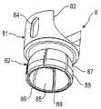
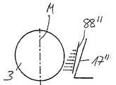
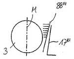
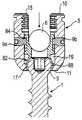
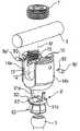
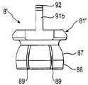
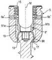
図1および2に示すように、第1実施形態の骨固定装置は、ねじが切られたシャフト2および頭部3を有する骨ねじの形態の骨固定要素1を備え、頭部3は、この実施形態においては球形の部分の形状を有する。頭部3は、ねじ込み工具と係合するための凹部4を有する。この骨固定装置は、さらに、骨固定要素1にロッド6を接続するためにロッド6を受ける受け部本体5を備える。さらに、内部ねじの形態の閉塞要素7が、受け部本体5内に固定するために設けられている。この骨固定装置はさらに、頭部を受け部本体5内に固定するための圧力要素8を含む。圧力要素8は、たとえばピン9a,9bによって、受け部本体5内に保持される。 As shown in FIGS. 1 and 2, the bone anchoring device of the first embodiment comprises a
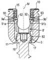
次に、受け部本体5について、図1および8〜14を参照して説明する。受け部本体5は、第1端10と、その反対側の第2端11と、第1および第2端を通る対称軸Mとを備える。また、対称軸Mと同軸の穴12が設けられる。第1端10に隣接する第1領域において、受け部本体5は、対称軸Mに関して対象なU字形状の凹部13を有し、この凹部13は、第2端11を向いた底部と、第1端10に向かって延びる、開放端を持つ2つの脚部14a,14bを有する。脚部14a,14bの領域には、閉塞要素としての内側ねじ7と螺合する雌ねじ15が設けられている。U字形状の凹部13により形成される溝は、複数の固定装置を接続するロッドを受けるような大きさを有する。第2端11近傍の第2領域には、穴12の円柱状部に続いて、円錐角をなして第2端11に向かって先細になる第1テーパ状部分16が設けられている。第1テーパ状部分16に続いて、円錐角をなして第2端11に向かって先細になる第2テーパ部分17が設けられ、その円錐角は、第1テーパ部の円錐角よりも小さい。第2端には開口18が設けられている。開口18の直径は頭部3の直径よりも大きく、穴12の内径よりも小さい。同軸の穴12は、ねじの頭部3のための収容空間を提供する。 Next, the receiving
脚部14a,14bの各々には、脚部14a,14bを貫通する穴20a,20bが、ピン9a,9bを受けるために設けられている。これらの穴は、各脚部のほぼ中央に位置している。 Each of the
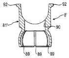
図1および3〜7からわかるように、圧力要素8は本質的に、ほぼ円筒状で、圧力要素8が穴12内を移動可能なように、穴12の内径よりもわずかに小さい外径を有する、第1部分81と、第1の部分よりも内側に窪み、穴12の内径よりも小さい最大外径を有する第2の部分82とを含む。第1の部分81は、第2の部分82とは反対側の端に、圧力要素8が受け部本体5内に位置するときにロッド6を受ける、U字状凹部83を有する。U字状の凹部の両側面において、圧力要素は外壁に、互いに対向するように配置され、その長手方向が受け部本体5の対称軸Mと平行になるように配された、長手の凹部84を備える。図4からわかるように、第1の部分81の横幅は、自由端に向かって小さくなっている。 As can be seen from FIGS. 1 and 3 to 7, the
第2の部分82はカラーと同様に形成され、第1の部分81側に第1の部分に対して窪んだ第1端と、中に球状の頭部3を締め付けるためにほぼ球状をなす中空の内部85とを備える。第2の部分82の第2端には、頭部3を導入するための開口86が設けられている。第2の部分82の外壁は、先細になっている第2の部分の開口86に近接する、球状をなす第1の部分87を備える。テーパ状の第2の部分88は、受け部本体の第2テーパ状部分17と協働する。圧力要素の第1の部分81はさらに、第2の部分82を貫く開口86から伸びる複数のスリット89を備える。スリット89の数および寸法は、第1の部分が、頭部3を挿入するときに頭部がスナップ嵌合するのに十分な可撓性を有するように設定される。さらに、圧力要素は、工具をねじに到達させるために設けられた同軸穴90を備える。 The
図8〜14からわかるように、圧力要素が穴12の内径よりもわずかに小さい最大外径を有するので、圧力要素は第1端10から受け部本体5に挿入することができる。圧力要素が一旦挿入されると、ピン9a,9bが穴20a,20b内に導入されて、長手の凹部83と係合し、それによって、受け部本体のU字状凹部13と位置がそろうU字状凹部83とともに圧力要素を保持し、圧力要素第1端を通って離脱することを防止する。圧力要素の第2の部分82が穴12の内径よりも小さい外径を有するため、また、圧力要素の第2の部分82が可撓性を有する外壁を有するため、第2の部分は、ねじの頭部が導入されるときに、収容空間19の範囲内で拡張可能である。 As can be seen from FIGS. 8 to 14, since the pressure element has a maximum outer diameter that is slightly smaller than the inner diameter of the
上述したすべての部品は、生体適合性のある材料、すなわち、たとえばステンレス鋼のような生体適合性のある金属、チタン、または、たとえばニチノールのような生体適合性のある金属合金により形成されるか、あるいは、たとえばPEEKのような生体適合性のある樹脂材料から形成される。 Are all the parts mentioned above made of a biocompatible material, i.e. a biocompatible metal such as stainless steel, titanium or a biocompatible metal alloy such as Nitinol? Alternatively, it is formed from a biocompatible resin material such as PEEK.
骨固定装置を組み立てるステップについて、以下、図8〜14に基づいて説明する。まず、圧力要素8が受け部本体に導入され、ピン9a,9bによって保持されるとき、開口86が受け部本体の第2端11に向けられるように、圧力要素の方向が定められる。図8に示すように、圧力要素8は、ねじの頭部3を挿入可能にする挿入状態である、最も上の位置にある。挿入状態においては、圧力要素の可撓性のある第2の部分が、収容空間19内において自由に位置する。挿入状態は、上昇運動に対して、この実施形態ではピンを凹部84の下端と係合して設けられた当接部(abutment)によって制限される。図9に示すように、次に、ねじの頭部3が開口18を通して収容空間19に収納され、その位置に、圧力要素8の第2の部分82が配置される。ねじの頭部3は開口86を通して、圧力要素の第2の部分82の中空の内部85に導入される。スリット89により可撓性が付与される壁によって、第2の部分は図9に示すように収容空間19内で拡張される。第2の部分は、ねじの頭部3を包囲するまでねじの頭部にスナップ嵌合する。ピンはまた、ねじの頭部が挿入されるときに、圧力要素8が開口する第2端11を貫いて離脱することを防止する。挿入状態においては、ねじの頭部3は受け部において旋回可能であり、また、圧力要素がこの位置にとどまれば、ねじの頭部は取外し可能である。圧力要素を一時的に挿入状態に保持するための手段(図示せず)が設けられてもよい。それに代えて、圧力要素を工具(図示せず)により挿入状態に保持することも可能である。 The steps for assembling the bone anchoring device will be described below with reference to FIGS. First, when the
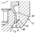
図11および12は、圧力要素の予備固定状態を示す。ねじの頭部が挿入され圧力要素がわずかに押し下げられると、圧力要素の第2の部分82の外壁が第1テーパ状部分16によって案内され、それによって、第2の部分82の外壁は受け部本体の第2テーパ状部分17と接触する。圧力要素の外壁のテーパ状の第2の部分88および第2テーパ状部分17は互いに係合し、それによって、圧力要素の第2の部分82がねじの頭部に対して予応力を作用し、頭部3を予備固定する。予備固定とは、手術中に生じる状態の下で、受け部本体5に対する骨固定要素1の角度位置が維持され、かつ、受け部本体またはねじ要素に付加的な力を作用させることのみで、緩めることができることを意味する。圧力要素の予備固定状態は圧力要素を手で押し下げることによって、あるいは、ロッドを挿入し内側ねじ7をねじ込むことによりロッドが圧力要素を押し下げて、圧力要素をわずかに下方に動かすことによって、達成され得る。 11 and 12 show the pre-fixed state of the pressure element. When the head of the screw is inserted and the pressure element is pushed down slightly, the outer wall of the
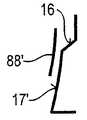
図13a、13bは、予備固定状態における、圧力要素の外側表面部分と受け部本体の内側表面部分との係合を示す。上述のように、表面17,88は、図13aに示すようにテーパ状にすることができる。それに代えて、表面88′,17′を、図13bに示すように丸くしてもよい。受け部本体5の第1テーパ状部分16は、案内のためのみに作用するものであり、省略してもよい。 Figures 13a, 13b show the engagement of the outer surface part of the pressure element and the inner surface part of the receiving body in the pre-fixed state. As mentioned above, the
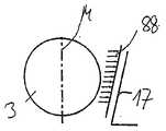
図13cにおいて、2つのテーパ状部分17,88は、ほぼ同じ角度で先細になっている。これにより、圧力要素の第2の部分88と受け部本体の先細になった部分17との間において、図中に矢印で示すようにほぼ均一な圧力分布が得られる。図13d,13eは、部分がそれぞれ異なった角度で先細になっている2つの異なった構造を示す。図13dは底部の主要接触領域を示し、図13eは部分17″′の上部の主要接触領域を示す。図13fは、圧力要素のテーパ状の第2の部分88″″と、受け部本体の丸くされた部分17″″とが示され、この丸くされた部分17″″の湾曲は、受け部本体の中央に向いている。そのような形状を有することにより、丸くされた部分に接触領域を位置させることができる。 In FIG. 13c, the two
図13g,13hには、受け部本体5の変形例の狭くする部分170が、互いに重なり合う2つの湾曲部分170a,170bによって形成される二重の球状領域を有し、それらの間に溝170cが形成されている。その湾曲は、中心軸Mに向けられている。同様に、変形された圧力要素180は、その下端に、湾曲部分170a,170bに対応する2つの逆に湾曲した部分180a,180bを有し、それらの間には稜180cが形成され、圧力要素の曲がり易い外側端部に外側稜180dが形成されている。 In FIGS. 13g and 13h, the narrowing
図13eに示すように、圧力要素180が下方へ移動すると、その最下端が溝170cを係合する。この部分において、頭部3の摩擦による締め付けが生じるが、それによってもなお、力が作用すると旋回させることができ、その力は、頭部3が挿入状態に導入されるときに頭部を旋回させるための力よりも大きい。これが予備固定状態である。図13hに示すように、圧力要素180をさらに押し下げることにより、圧力要素180の湾曲部分は狭くする部分170の湾曲部分と係合し、頭部が最終的に固定される。 As shown in FIG. 13e, when the
固定状態である第3の位置が、図14に示される。固定状態は、ねじの頭部3が最終的に受け部本体内に固定されるときの、圧力要素の位置として定義される。この位置では、圧力要素の先細になった外側表面が、大きな領域にわたって、受け部本体の第2の先細になった部分と係合する。それによって、圧力要素の第2の部分の可撓性のある壁が頭部3に押し付けられ、その結果として頭部3が固定される。この位置は、最終的に内側ねじ7を締め付け、それによりロッド6を押し下げることによって達成される。 The third position, which is fixed, is shown in FIG. The fixed state is defined as the position of the pressure element when the
使用時には、骨固定装置は、たとえば、適切な骨固定要素1が選択され、挿入された圧力要素とともに受け部本体に導入されるというような態様によって、予備組立てを行なうことができる。圧力要素をわずかに押し下げることによっても、予備組立ての状態をもたらすことができる。その後、ねじ要素が骨にねじ込まれる。頭部3の凹部4に、同軸穴12および穴90を通して、ねじ工具を到達させることができる。受け部を、それに接続されるロッドに対して正確に位置をそろえるために、手で、あるいは道具を用いて、受け部に付加的な力が加えられる。ロッドの位置を他の骨固定装置に対して一旦正しく位置決めされると、内側ねじ7が締め付けられ、それによって、圧力要素を固定状態まで下降させる。内側ねじの最終的な締め付けにより、ロッドおよび頭部が同時に固定される。 In use, the bone anchoring device can be preassembled, for example in such a way that an appropriate
骨固定装置は、製造者により、あるいは手術中またはその準備の際、あるいはその他のどのようなときにおいても、予備組み立てを行なうことができる。好都合なことに、外科医は、手術の前に、臨床用途に特有の要求にしたがって、骨固定要素に必要な受け部を選ぶことができる。このような骨固定装置の構造により、固定部分の直径、長さ、および他の形状の観点から、適切な骨固定要素を選ぶことができる。よって、複数の受け部および数個の骨固定要素を含むモジュラーシステムが提供され、それから個別に選んで適用することができる。 The bone anchoring device can be pre-assembled by the manufacturer, during or during surgery, or at any other time. Conveniently, the surgeon can select the required receptacle for the bone anchoring element according to the requirements specific to the clinical application prior to surgery. Due to the structure of such a bone anchoring device, an appropriate bone anchoring element can be selected in terms of the diameter, length and other shapes of the anchoring portion. Thus, a modular system comprising a plurality of receptacles and several bone anchoring elements is provided, from which it can be individually selected and applied.
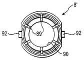
次に、第2実施形態の骨固定装置について、図15〜26に基づいて説明する。第1実施形態の部品と同一の部品については、同じ参照番号を付して、その説明を省略する。第2実施形態の骨固定装置は、圧力要素およびピンの構造において、第1実施形態と異なる。圧力要素8′は、第1の部分において圧力要素8と異なる。圧力要素8′の第1の部分81′には、ほぼ円柱の部分の形状を有する、ロッド6をガイドするための浅い窪み83′が設けられている。圧力要素8′の第1の部分81′はさらに、2つの直立する弾力のあるの指状部91a,91bを含み、これらは、窪み83′の両側部側から受け部本体の第1端10の方向に延びている。これらの直立する指状部は、それらの自由端のそれぞれに、外側を向く部分92を有する。少なくとも指状部の領域においては、弾力のある指状部が移動可能であるように、第1の部分81′の外径は、同軸穴12の内径よりも小さくなっている。 Next, the bone anchoring device of 2nd Embodiment is demonstrated based on FIGS. Components that are the same as those of the first embodiment are given the same reference numerals, and descriptions thereof are omitted. The bone anchoring device of the second embodiment differs from the first embodiment in the structure of the pressure element and the pin. The pressure element 8 'differs from the
ピン9a,9bはそれぞれ、平坦にされた部分93を有し、その部分93の幅は、弾力のある指状部の外側に延びる部分92の幅とほぼ同じである。ピンが穴20a,20bに挿入されると、部分93は図20に示すように、受け部本体5の同軸穴12の中まで延びている。この構造により、圧力要素8′のための当接部が提供される。 Each of the
次に、第2実施形態による骨固定装置の組み立てについて、図20〜25に基づいて説明する。まず図20に示すように、圧力要素8′が第1端10から受け部本体5に挿入される。その後、ピン9a′,9b′が脚部の穴に挿入される。圧力要素8′は、弾力のある指状部の外側へ伸びる部分92がピンの平坦にされた部分93の上に配置するような位置にある。この位置において、圧力要素8′は挿入状態にある。その後、ねじの頭部が、圧力要素8′の第2の部分82がねじの頭部3を包囲するまで、開口18および86を通して挿入される。その後、図22に示すように、圧力要素8′がわずかに下降して、予備固定状態に入る。それによって、弾力のある指状部91a,91bは、外側に延びる部分92がピンの平坦にされた部分93の周りを動くことにより、内側に押し付けられる。図23に示すように、外側に延びる部分92が外側へ移動し、平坦にされた部分93が圧力要素のための当接部を構成する。この予備固定状態において、第2の部分82のテーパ状の外側表面部分が、受け部本体のテーパ状部分17と係合する。ピンが止め部材として作用するため、予備固定状態が確実になる。 Next, assembly of the bone anchoring device according to the second embodiment will be described with reference to FIGS. First, as shown in FIG. 20, the
ロッドを挿入し、内側ねじ7をねじ込むことにより、圧力要素は、図26に示すような最終的固定状態に達するまで、さらに圧力要素を下降させる。 By inserting the rod and screwing in the
骨固定装置の臨床用途は、第1実施形態のものと同じである。
示された実施形態をさらに変更することが可能である。たとえば、骨固定要素の頭部は、円柱形のような他の形状を有してもよい。頭部をたとえば円柱形にすることにより、単一の軸まわりに受け部に対してねじ要素を旋回可能にする単軸骨ねじが供給される。頭部3を、円錐形状にし、圧力要素の中空の内側部85をこの形状に適合させることも可能である。さらなる変形例においては、受け部本体5または少なくとも圧力要素の第2の部分82は、ある程度弾性を有する生体適合性のある樹脂材料で形成される。この場合、スリットは設けなくてもよい。The clinical use of the bone anchoring device is the same as that of the first embodiment.
The illustrated embodiment can be further modified. For example, the head of the bone anchoring element may have other shapes such as a cylindrical shape. A monoaxial bone screw is provided that allows the screw element to pivot relative to the receiver about a single axis, for example by making the head cylindrical. It is also possible for the
第2実施形態に代えて、圧力要素の部分と協働する受け部本体に弾力部が設けられてもよい。一般的には、ピンが、圧力要素の係止部の目的を果たす唯一の例であるが、スナップリングやその他の構造物を用いることも考えられる。 Instead of the second embodiment, a resilient portion may be provided in the receiving portion main body that cooperates with the pressure element portion. In general, a pin is the only example that serves the purpose of a locking element for a pressure element, but it is also conceivable to use a snap ring or other structure.
受け部本体は、一つの方向により大きな角度を付与可能にするために、傾斜した回後端を有してもよい。圧力要素の第2の部分82の外側表面は、テーパ上であってもよく、また、受け部本体の第2の部分17が内側に湾曲していてもよい。 The receiving part body may have an inclined back end in order to be able to give a larger angle in one direction. The outer surface of the
今回開示された実施の形態は、すべての点で例示であって制限的なものではないと考えられるべきである。本発明の範囲は上記した説明ではなくて特許請求の範囲によって示され、特許請求の範囲と均等の意味および範囲内でのすべての変更が含まれることが意図される。 The embodiment disclosed this time should be considered as illustrative in all points and not restrictive. The scope of the present invention is defined by the terms of the claims, rather than the description above, and is intended to include any modifications within the scope and meaning equivalent to the terms of the claims.
1 骨固定要素、2 シャフト、3 頭部、4 凹部、5 受け部本体、6 ロッド、7 閉塞要素、8,8′ 180 圧力要素、9a,9b ピン、10 第1端、11 第2端、12 穴、13 凹部、14a,14b 脚部、16 第1テーパ状部分、17 第2テーパ状部分,18 開口、19 収容空間、20a,20b 穴、81,81′ 第1の部分、82 第2の部分、83 U字状凹部、83′ 窪み、86 開口、87 第1の部分、88 第2の部分、89 スリット、90 同軸穴、91a,91b 指状部、170a,170b 湾曲部分、170c 溝、180c 稜、180d 外側稜、M 対称軸。 DESCRIPTION OF
Claims (15)
Translated fromJapanese前記ロッドを受ける溝(13)を有する受け部本体(5)と、
骨固定要素(1)の頭部(3)を導入する開口(18)を有し、該頭部(3)を収容するための収容空間(19)と、
前記頭部を締め付けるための可撓性部(83,83′)を有する、前記収容空間(19)の少なくとも一部に配置された圧力要素(8,8′)とを備え、
前記圧力要素(8,8′)は、前記受け部本体(5)内において、前記頭部の導入を可能にする挿入状態、前記頭部が前記受け部内において固定される固定状態、および、前記頭部が前記圧力要素によって作用する予応力により締め付けられる予備固定状態をとることができる、受け部。A receiving portion for receiving the rod to couple the rod to the bone anchoring element,
A receiving body (5) having a groove (13) for receiving the rod;
An opening (18) for introducing the head (3) of the bone anchoring element (1), a receiving space (19) for receiving the head (3);
A pressure element (8, 8 ') arranged in at least a part of the accommodating space (19), having a flexible part (83, 83') for tightening the head;
The pressure element (8, 8 ') is inserted in the receiving portion main body (5) to enable the introduction of the head, a fixed state in which the head is fixed in the receiving portion, and the A receiving part capable of taking a pre-fixed state in which a head is tightened by a pre-stress acting by the pressure element.
Applications Claiming Priority (4)
| Application Number | Priority Date | Filing Date | Title |
|---|---|---|---|
| US15430609P | 2009-02-20 | 2009-02-20 | |
| EP09002468.8AEP2221013B1 (en) | 2009-02-20 | 2009-02-20 | Receiving part for receiving a rod for coupling the rod to a bone anchoring element and a bone anchoring device with such a receiving part |
| US61/154,306 | 2009-02-20 | ||
| EP09002468.8 | 2009-02-20 |
Related Child Applications (1)
| Application Number | Title | Priority Date | Filing Date |
|---|---|---|---|
| JP2014098461ADivisionJP5865428B2 (en) | 2009-02-20 | 2014-05-12 | Receiving part for receiving the rod and connecting it to the bone anchoring element, and a bone anchoring device having such a receiving part |
Publications (2)
| Publication Number | Publication Date |
|---|---|
| JP2010194309Atrue JP2010194309A (en) | 2010-09-09 |
| JP5622402B2 JP5622402B2 (en) | 2014-11-12 |
Family
ID=40578492
Family Applications (2)
| Application Number | Title | Priority Date | Filing Date |
|---|---|---|---|
| JP2010030782AActiveJP5622402B2 (en) | 2009-02-20 | 2010-02-16 | Receiving part for receiving the rod and connecting it to the bone anchoring element, and a bone anchoring device having such a receiving part |
| JP2014098461AActiveJP5865428B2 (en) | 2009-02-20 | 2014-05-12 | Receiving part for receiving the rod and connecting it to the bone anchoring element, and a bone anchoring device having such a receiving part |
Family Applications After (1)
| Application Number | Title | Priority Date | Filing Date |
|---|---|---|---|
| JP2014098461AActiveJP5865428B2 (en) | 2009-02-20 | 2014-05-12 | Receiving part for receiving the rod and connecting it to the bone anchoring element, and a bone anchoring device having such a receiving part |
Country Status (7)
| Country | Link |
|---|---|
| US (6) | US8926671B2 (en) |
| EP (3) | EP2221013B1 (en) |
| JP (2) | JP5622402B2 (en) |
| KR (1) | KR101673524B1 (en) |
| CN (1) | CN101810510B (en) |
| ES (2) | ES2548580T3 (en) |
| TW (1) | TWI527559B (en) |
Cited By (11)
| Publication number | Priority date | Publication date | Assignee | Title |
|---|---|---|---|---|
| JP2012110700A (en)* | 2010-11-22 | 2012-06-14 | Biedermann Technologies Gmbh & Co Kg | Polyaxial bone anchoring device, and method and caulking tool for manufacturing the same |
| JP2012135618A (en)* | 2010-12-27 | 2012-07-19 | Biedermann Technologies Gmbh & Co Kg | Polyaxial bone anchoring device |
| JP2013154172A (en)* | 2012-01-30 | 2013-08-15 | Biedermann Technologies Gmbh & Co Kg | Bone anchoring device and method for manufacturing the same |
| JP2013244412A (en)* | 2012-05-29 | 2013-12-09 | Biedermann Technologies Gmbh & Co Kg | Receiving part and bone anchoring device including the same |
| JP2014500068A (en)* | 2008-08-01 | 2014-01-09 | ロジャー・ピー・ジャクソン | A polyaxial bone anchor having a pop-on shank, a friction-fitted and fully constrained retainer, an insert, and an instrument receiving component |
| JP2014018664A (en)* | 2012-07-18 | 2014-02-03 | Biedermann Technologies Gmbh & Co Kg | Polyaxial bone anchoring device |
| JP2014151203A (en)* | 2013-02-11 | 2014-08-25 | Biedermann Technologies Gmbh & Co Kg | Coupling assembly for coupling rod to bone anchoring element, and bone anchoring device with such coupling assembly |
| CN104771220A (en)* | 2014-01-13 | 2015-07-15 | 比德尔曼技术有限责任两合公司 | Coupling assembly for coupling a rod to a bone anchoring element, and polyaxial bone anchoring device |
| JP2018064966A (en)* | 2011-03-24 | 2018-04-26 | ロジャー・ピー・ジャクソン | Polyaxial bone anchor with compound articulation and pop-on shank |
| KR20180059899A (en)* | 2015-09-30 | 2018-06-05 | 상하이 산유 메디컬 씨오., 엘티디. | Transverse shifting screw tail, transversely adjustable spinal screw and implantation method |
| JP2022068848A (en)* | 2020-10-22 | 2022-05-10 | ビーダーマン・テクノロジーズ・ゲゼルシャフト・ミット・ベシュレンクテル・ハフツング・ウント・コンパニー・コマンディートゲゼルシャフト | Coupling device for connecting the rod to the bone anchor |
Families Citing this family (115)
| Publication number | Priority date | Publication date | Assignee | Title |
|---|---|---|---|---|
| US7833250B2 (en) | 2004-11-10 | 2010-11-16 | Jackson Roger P | Polyaxial bone screw with helically wound capture connection |
| US8876868B2 (en) | 2002-09-06 | 2014-11-04 | Roger P. Jackson | Helical guide and advancement flange with radially loaded lip |
| US7377923B2 (en) | 2003-05-22 | 2008-05-27 | Alphatec Spine, Inc. | Variable angle spinal screw assembly |
| US8366753B2 (en) | 2003-06-18 | 2013-02-05 | Jackson Roger P | Polyaxial bone screw assembly with fixed retaining structure |
| US8926670B2 (en) | 2003-06-18 | 2015-01-06 | Roger P. Jackson | Polyaxial bone screw assembly |
| US7766915B2 (en) | 2004-02-27 | 2010-08-03 | Jackson Roger P | Dynamic fixation assemblies with inner core and outer coil-like member |
| US7776067B2 (en) | 2005-05-27 | 2010-08-17 | Jackson Roger P | Polyaxial bone screw with shank articulation pressure insert and method |
| US7503924B2 (en) | 2004-04-08 | 2009-03-17 | Globus Medical, Inc. | Polyaxial screw |
| US8475495B2 (en) | 2004-04-08 | 2013-07-02 | Globus Medical | Polyaxial screw |
| US8926672B2 (en) | 2004-11-10 | 2015-01-06 | Roger P. Jackson | Splay control closure for open bone anchor |
| US9980753B2 (en)* | 2009-06-15 | 2018-05-29 | Roger P Jackson | pivotal anchor with snap-in-place insert having rotation blocking extensions |
| US7875065B2 (en) | 2004-11-23 | 2011-01-25 | Jackson Roger P | Polyaxial bone screw with multi-part shank retainer and pressure insert |
| US8444681B2 (en) | 2009-06-15 | 2013-05-21 | Roger P. Jackson | Polyaxial bone anchor with pop-on shank, friction fit retainer and winged insert |
| US9168069B2 (en) | 2009-06-15 | 2015-10-27 | Roger P. Jackson | Polyaxial bone anchor with pop-on shank and winged insert with lower skirt for engaging a friction fit retainer |
| US7901437B2 (en) | 2007-01-26 | 2011-03-08 | Jackson Roger P | Dynamic stabilization member with molded connection |
| US10792074B2 (en) | 2007-01-22 | 2020-10-06 | Roger P. Jackson | Pivotal bone anchor assemly with twist-in-place friction fit insert |
| US8979904B2 (en) | 2007-05-01 | 2015-03-17 | Roger P Jackson | Connecting member with tensioned cord, low profile rigid sleeve and spacer with torsion control |
| EP2484300B1 (en)* | 2008-09-05 | 2015-05-20 | Biedermann Technologies GmbH & Co. KG | Stabilization device for bones, in particular for the spinal column |
| ES2548580T3 (en) | 2009-02-20 | 2015-10-19 | Biedermann Technologies Gmbh & Co. Kg | Receiving part for housing a rod for coupling to a bone anchoring element and bone anchoring device that includes such receiving part |
| US9668771B2 (en) | 2009-06-15 | 2017-06-06 | Roger P Jackson | Soft stabilization assemblies with off-set connector |
| US11229457B2 (en) | 2009-06-15 | 2022-01-25 | Roger P. Jackson | Pivotal bone anchor assembly with insert tool deployment |
| CN103826560A (en) | 2009-06-15 | 2014-05-28 | 罗杰.P.杰克逊 | Polyaxial Bone Anchor with Socket Stem and Winged Inserts with Friction Fit Compression Collars |
| US8998959B2 (en)* | 2009-06-15 | 2015-04-07 | Roger P Jackson | Polyaxial bone anchors with pop-on shank, fully constrained friction fit retainer and lock and release insert |
| US11464549B2 (en) | 2009-06-15 | 2022-10-11 | Roger P. Jackson | Pivotal bone anchor assembly with horizontal tool engagement grooves and insert with upright arms having flared outer portions |
| EP2283786B1 (en) | 2009-08-12 | 2015-06-17 | Biedermann Technologies GmbH & Co. KG | A receiving part for receiving a rod for coupling the rod to a bone anchoring element |
| EP2286748B1 (en) | 2009-08-20 | 2014-05-28 | Biedermann Technologies GmbH & Co. KG | Bone anchoring device |
| US20240341816A1 (en)* | 2009-10-05 | 2024-10-17 | Roger P. Jackson | Pivotal bone anchor assembly with temporary positional locking by tooling |
| EP2485654B1 (en) | 2009-10-05 | 2021-05-05 | Jackson P. Roger | Polyaxial bone anchor with non-pivotable retainer and pop-on shank, some with friction fit |
| US10172647B2 (en)* | 2009-11-16 | 2019-01-08 | Nexxt Spine, LLC | Poly-axial implant fixation system |
| WO2011106339A1 (en)* | 2010-02-23 | 2011-09-01 | K2M, Inc. | Polyaxial bone screw assembly |
| US12383311B2 (en) | 2010-05-14 | 2025-08-12 | Roger P. Jackson | Pivotal bone anchor assembly and method for use thereof |
| WO2012030712A1 (en)* | 2010-08-30 | 2012-03-08 | Zimmer Spine, Inc. | Polyaxial pedicle screw |
| AU2011324058A1 (en) | 2010-11-02 | 2013-06-20 | Roger P. Jackson | Polyaxial bone anchor with pop-on shank and pivotable retainer |
| EP2460484A1 (en)* | 2010-12-01 | 2012-06-06 | FACET-LINK Inc. | Variable angle bone screw fixation assembly |
| EP2737864B1 (en)* | 2010-12-10 | 2017-04-12 | Biedermann Technologies GmbH & Co. KG | Receiving part for receiving a rod for coupling the rod to a bone anchoring element and a bone anchoring device |
| CN102133132B (en)* | 2010-12-31 | 2013-01-02 | 上海微创骨科医疗科技有限公司 | Dynamic screw implant for pedicle of vertebral arch |
| US9198694B2 (en) | 2011-07-15 | 2015-12-01 | Globus Medical, Inc. | Orthopedic fixation devices and methods of installation thereof |
| US9358047B2 (en) | 2011-07-15 | 2016-06-07 | Globus Medical, Inc. | Orthopedic fixation devices and methods of installation thereof |
| US9186187B2 (en) | 2011-07-15 | 2015-11-17 | Globus Medical, Inc. | Orthopedic fixation devices and methods of installation thereof |
| US8888827B2 (en) | 2011-07-15 | 2014-11-18 | Globus Medical, Inc. | Orthopedic fixation devices and methods of installation thereof |
| US9993269B2 (en)* | 2011-07-15 | 2018-06-12 | Globus Medical, Inc. | Orthopedic fixation devices and methods of installation thereof |
| EP2559389B1 (en)* | 2011-08-18 | 2013-04-03 | Biedermann Technologies GmbH & Co. KG | Polyaxial bone anchoring device |
| EP2574297B1 (en) | 2011-09-30 | 2015-11-11 | Biedermann Technologies GmbH & Co. KG | Bone anchoring device and tool cooperating with such a bone anchoring device |
| EP2606841B1 (en)* | 2011-12-23 | 2016-03-09 | Biedermann Technologies GmbH & Co. KG | Polyaxial bone anchoring device |
| US8911479B2 (en) | 2012-01-10 | 2014-12-16 | Roger P. Jackson | Multi-start closures for open implants |
| US9427260B2 (en) | 2012-03-01 | 2016-08-30 | Globus Medical, Inc. | Closed-head polyaxial and monaxial screws |
| ES2563785T3 (en)* | 2012-06-01 | 2016-03-16 | Biedermann Technologies Gmbh & Co. Kg | Polyaxial bone anchoring device |
| EP2674123B1 (en) | 2012-06-11 | 2018-03-21 | Biedermann Technologies GmbH & Co. KG | Polyaxial bone anchoring device |
| US9763702B2 (en)* | 2012-11-16 | 2017-09-19 | DePuy Synthes Products, Inc. | Bone fixation assembly |
| US8911478B2 (en) | 2012-11-21 | 2014-12-16 | Roger P. Jackson | Splay control closure for open bone anchor |
| US10058354B2 (en) | 2013-01-28 | 2018-08-28 | Roger P. Jackson | Pivotal bone anchor assembly with frictional shank head seating surfaces |
| US20220160402A1 (en)* | 2013-02-09 | 2022-05-26 | Vertiscrew, Llc | Bone screw |
| US8852239B2 (en) | 2013-02-15 | 2014-10-07 | Roger P Jackson | Sagittal angle screw with integral shank and receiver |
| EP2772212B1 (en) | 2013-03-01 | 2019-05-08 | Biedermann Technologies GmbH & Co. KG | Instrument for inserting a bone anchoring element and system of such an instrument and a polyaxial bone anchoring element |
| US20140336709A1 (en)* | 2013-03-13 | 2014-11-13 | Baxano Surgical, Inc. | Multi-threaded pedicle screw system |
| TWI572319B (en)* | 2013-03-27 | 2017-03-01 | 梓源生技有限公司 | Pedicle screw system |
| US20150073488A1 (en)* | 2013-09-09 | 2015-03-12 | James A. Rinner | Spinal stabilization system |
| EP2851021B1 (en) | 2013-09-19 | 2016-12-14 | Biedermann Technologies GmbH & Co. KG | Coupling assembly for coupling a rod to a bone anchoring element, polyaxial bone anchoring device and modular stabilization device |
| US9566092B2 (en) | 2013-10-29 | 2017-02-14 | Roger P. Jackson | Cervical bone anchor with collet retainer and outer locking sleeve |
| EP2873383B1 (en) | 2013-11-14 | 2016-10-19 | Biedermann Technologies GmbH & Co. KG | Polyaxial bone anchoring device with enlarged pivot angle |
| US9717533B2 (en) | 2013-12-12 | 2017-08-01 | Roger P. Jackson | Bone anchor closure pivot-splay control flange form guide and advancement structure |
| US9451993B2 (en) | 2014-01-09 | 2016-09-27 | Roger P. Jackson | Bi-radial pop-on cervical bone anchor |
| US10039572B2 (en)* | 2014-02-17 | 2018-08-07 | FloSpine LLC | Polyaxial bone anchor incorporating a two position saddle assembly |
| CN103908331B (en)* | 2014-04-02 | 2015-10-28 | 山东冠龙医疗用品有限公司 | A kind of Minimally Invasive Surgery pedicle nail |
| AU2015246029B2 (en) | 2014-04-10 | 2018-11-29 | Medacta International Sa | Device for fixing surgical implants in place and relative assembly procedure with anchoring means |
| US9597119B2 (en) | 2014-06-04 | 2017-03-21 | Roger P. Jackson | Polyaxial bone anchor with polymer sleeve |
| US10064658B2 (en) | 2014-06-04 | 2018-09-04 | Roger P. Jackson | Polyaxial bone anchor with insert guides |
| US9924975B2 (en) | 2014-10-21 | 2018-03-27 | Roger P. Jackson | Bone anchor having a snap-fit assembly |
| US10543021B2 (en)* | 2014-10-21 | 2020-01-28 | Roger P. Jackson | Pivotal bone anchor assembly having an open ring positioner for a retainer |
| US11219471B2 (en) | 2014-10-21 | 2022-01-11 | Roger P. Jackson | Pivotal bone anchor receiver having an insert with post-placement tool deployment |
| EP3031415B1 (en) | 2014-12-10 | 2018-10-31 | Biedermann Technologies GmbH & Co. KG | Coupling assembly and polyaxial bone anchoring device comprising the same |
| US10219844B2 (en)* | 2015-03-25 | 2019-03-05 | Robert Reid, Inc. | Spine fixation device and spine fixation system |
| EP3280339A1 (en)* | 2015-04-07 | 2018-02-14 | K2M, Inc. | Spinal stabilization device, system, and method of use |
| WO2016170199A1 (en) | 2015-04-23 | 2016-10-27 | Sanpera Trigueros Ignacio | Fixation system for spinal instrumentation |
| EP3092963B1 (en) | 2015-05-12 | 2017-07-12 | Biedermann Technologies GmbH & Co. KG | Coupling device for coupling a rod to a bone anchoring element and bone anchoring device with such a coupling device |
| EP3092962B1 (en) | 2015-05-12 | 2017-10-04 | Biedermann Technologies GmbH & Co. KG | Instrument for use with a polyaxial bone anchoring device and system including the instrument and a polyaxial bone anchoring device |
| DE102015008036A1 (en) | 2015-06-09 | 2016-12-15 | Signus Medizintechnik Gmbh | Pedicle screw with tulip |
| EP3106110B1 (en) | 2015-06-16 | 2017-10-11 | Biedermann Technologies GmbH & Co. KG | Extension device for a bone anchor |
| EP3120791B1 (en) | 2015-07-24 | 2017-11-22 | Biedermann Technologies GmbH & Co. KG | Polyaxial bone anchoring device and instrument for use with the same |
| US20170086886A1 (en)* | 2015-09-30 | 2017-03-30 | Amendia, Inc. | Modular bone screw assembly |
| EP3184063B1 (en)* | 2015-12-21 | 2019-07-10 | Biedermann Technologies GmbH & Co. KG | Polyaxial bone anchoring device |
| CN108697445B (en) | 2016-02-26 | 2022-04-19 | 美多斯国际有限公司 | Polyaxial bone fixation element |
| US10485594B2 (en)* | 2016-10-04 | 2019-11-26 | Amendia, Inc. | Modular tulip assembly |
| US11154331B2 (en) | 2016-10-04 | 2021-10-26 | Spinal Elements, Inc. | Modular tulip assembly |
| KR101868694B1 (en)* | 2016-10-21 | 2018-06-18 | 주식회사 지비에스커먼웰스 | Apparatus of bone fixation screw and fastening method thereof |
| US10595907B2 (en)* | 2017-02-16 | 2020-03-24 | Rubicon Spine Llc | Polyaxial pedicle screw |
| US11298156B2 (en) | 2017-03-30 | 2022-04-12 | K2M, Inc. | Modular screw |
| AU2018243875B2 (en) | 2017-03-30 | 2022-05-26 | K2M, Inc. | Bone anchor apparatus and method of use thereof |
| WO2018183486A1 (en) | 2017-03-30 | 2018-10-04 | K2M, Inc. | Modular offset screw |
| US11026730B2 (en) | 2017-05-10 | 2021-06-08 | Medos International Sarl | Bone anchors with drag features and related methods |
| US10299843B2 (en)* | 2017-06-02 | 2019-05-28 | Bret Michael Berry | Tulip head and collet for a poly axial screw |
| US10610265B1 (en) | 2017-07-31 | 2020-04-07 | K2M, Inc. | Polyaxial bone screw with increased angulation |
| CN107693098B (en)* | 2017-10-31 | 2024-02-06 | 李照文 | Anti-loosening pedicle screw rod system |
| EP3510954B1 (en)* | 2018-01-10 | 2021-07-28 | Biedermann Technologies GmbH & Co. KG | Polyaxial bone anchoring device and system of an instrument and a polyaxial bone anchoring device |
| US11596449B2 (en) | 2018-09-13 | 2023-03-07 | Roger P. Jackson | Pivotal bone anchor assembly with modular receiver and universal shank head |
| WO2020097691A1 (en)* | 2018-11-16 | 2020-05-22 | Southern Cross Patents Pty Ltd | Pedicle screws |
| WO2020102787A1 (en) | 2018-11-16 | 2020-05-22 | Surber, James L. | Pivotal bone anchor assembly having a deployable collet insert with internal pressure ring |
| US11219470B2 (en) | 2019-07-30 | 2022-01-11 | Spine Wave, Inc. | Modular tensioned spinal screw |
| DE102019005374A1 (en) | 2019-07-30 | 2021-02-04 | Signus Medizintechnik Gmbh | SPINE IMPLANT CONNECTION DEVICE |
| DE102019005376A1 (en) | 2019-07-30 | 2021-02-04 | Signus Medizintechnik Gmbh | CONNECTING DEVICE FOR SPINE SUPPORT |
| EP3785649B1 (en) | 2019-08-30 | 2022-08-03 | Biedermann Technologies GmbH & Co. KG | Bone anchoring device |
| EP3831322B1 (en) | 2019-12-06 | 2025-03-19 | Biedermann Technologies GmbH & Co. KG | Coupling device for coupling a rod to a bone anchor |
| WO2021127251A1 (en) | 2019-12-17 | 2021-06-24 | Jackson Roger P | Bone anchor assembly with closed ring retainer and internal snap ring |
| EP3871624B1 (en) | 2020-02-25 | 2023-07-19 | Biedermann Technologies GmbH & Co. KG | Bone anchoring device |
| USD956233S1 (en)* | 2020-04-24 | 2022-06-28 | Solco Biomedical Co., Ltd. | Cervical screw |
| WO2021263088A1 (en) | 2020-06-26 | 2021-12-30 | K2M, Inc. | Modular head assembly |
| WO2022108875A1 (en) | 2020-11-19 | 2022-05-27 | K2M, Inc. | Modular head assembly for spinal fixation |
| US12364515B2 (en) | 2021-03-05 | 2025-07-22 | Medos International Sàrl | Multi-feature polyaxial screw |
| EP4111992B1 (en) | 2021-07-01 | 2024-01-31 | Biedermann Technologies GmbH & Co. KG | Bone anchoring device |
| US11751915B2 (en) | 2021-07-09 | 2023-09-12 | Roger P. Jackson | Modular spinal fixation system with bottom-loaded universal shank heads |
| EP4260823B1 (en)* | 2022-04-11 | 2024-10-09 | Biedermann Technologies GmbH & Co. KG | Coupling device for coupling a rod to a bone anchoring element and method of manufacturing the same |
| EP4580530A1 (en)* | 2022-09-01 | 2025-07-09 | Getset Surgical SA | Bone securing systems |
| WO2024081268A1 (en)* | 2022-10-10 | 2024-04-18 | Astura Medical Inc. | Modular tulip assembly |
| US20240277379A1 (en)* | 2023-02-22 | 2024-08-22 | Nexxt Spine, LLC | Modular bone screw fixation system |
| WO2024216074A1 (en)* | 2023-04-13 | 2024-10-17 | Warsaw Orthopedic, Inc. | Devices and systems for treating spinal disorders |
Citations (7)
| Publication number | Priority date | Publication date | Assignee | Title |
|---|---|---|---|---|
| JPH08257035A (en)* | 1995-03-15 | 1996-10-08 | Juergen Harms | Anchor component |
| JPH10225467A (en)* | 1996-10-18 | 1998-08-25 | Spinal Innovations | Spinal implant fixing assembly |
| JPH11318933A (en)* | 1998-04-03 | 1999-11-24 | Spinal Innov Llc | Spine fixing assembly, method, implant and insertion body |
| JP2001505469A (en)* | 1996-12-12 | 2001-04-24 | ジンテーズ アクチエンゲゼルシャフト クール | Device for joining longitudinal members to pedicle screws |
| WO2007038350A2 (en)* | 2005-09-23 | 2007-04-05 | Synthes (Usa) | Bone support apparatus |
| US20080243193A1 (en)* | 2005-05-25 | 2008-10-02 | Ensign Michael D | Low Profile Pedicle Screw Assembly |
| JP2008541880A (en)* | 2005-05-25 | 2008-11-27 | アルパインスパイン リミテッド ライアビリティ カンパニー | Pedicle screw and rod assembly |
Family Cites Families (55)
| Publication number | Priority date | Publication date | Assignee | Title |
|---|---|---|---|---|
| DE19936286C2 (en)* | 1999-08-02 | 2002-01-17 | Lutz Biedermann | bone screw |
| US6485491B1 (en)* | 2000-09-15 | 2002-11-26 | Sdgi Holdings, Inc. | Posterior fixation system |
| US6368321B1 (en)* | 2000-12-04 | 2002-04-09 | Roger P. Jackson | Lockable swivel head bone screw |
| DE10064571C2 (en)* | 2000-12-22 | 2003-07-10 | Juergen Harms | fixing |
| US7678136B2 (en) | 2002-02-04 | 2010-03-16 | Spinal, Llc | Spinal fixation assembly |
| US7066937B2 (en) | 2002-02-13 | 2006-06-27 | Endius Incorporated | Apparatus for connecting a longitudinal member to a bone portion |
| US6837889B2 (en) | 2002-03-01 | 2005-01-04 | Endius Incorporated | Apparatus for connecting a longitudinal member to a bone portion |
| US6716214B1 (en)* | 2003-06-18 | 2004-04-06 | Roger P. Jackson | Polyaxial bone screw with spline capture connection |
| US7322981B2 (en)* | 2003-08-28 | 2008-01-29 | Jackson Roger P | Polyaxial bone screw with split retainer ring |
| US7087057B2 (en) | 2003-06-27 | 2006-08-08 | Depuy Acromed, Inc. | Polyaxial bone screw |
| AU2003304415A1 (en)* | 2003-07-25 | 2005-03-07 | Traiber, S.A. | Vertebral fixation device for the treatment of spondylolisthesis |
| US7857834B2 (en)* | 2004-06-14 | 2010-12-28 | Zimmer Spine, Inc. | Spinal implant fixation assembly |
| US20070239159A1 (en)* | 2005-07-22 | 2007-10-11 | Vertiflex, Inc. | Systems and methods for stabilization of bone structures |
| US7604655B2 (en)* | 2004-10-25 | 2009-10-20 | X-Spine Systems, Inc. | Bone fixation system and method for using the same |
| US20060161153A1 (en)* | 2004-10-25 | 2006-07-20 | Alphaspine, Inc. | Pedicle screw systems and methods of assembling/installing the same |
| US7691129B2 (en)* | 2004-10-27 | 2010-04-06 | Felix Brent A | Spinal stabilizing system |
| US9980753B2 (en) | 2009-06-15 | 2018-05-29 | Roger P Jackson | pivotal anchor with snap-in-place insert having rotation blocking extensions |
| US8444681B2 (en) | 2009-06-15 | 2013-05-21 | Roger P. Jackson | Polyaxial bone anchor with pop-on shank, friction fit retainer and winged insert |
| US7445627B2 (en)* | 2005-01-31 | 2008-11-04 | Alpinespine, Llc | Polyaxial pedicle screw assembly |
| US10076361B2 (en)* | 2005-02-22 | 2018-09-18 | Roger P. Jackson | Polyaxial bone screw with spherical capture, compression and alignment and retention structures |
| TWI375545B (en)* | 2005-04-25 | 2012-11-01 | Synthes Gmbh | Bone anchor with locking cap and method of spinal fixation |
| EP1749489B1 (en) | 2005-08-03 | 2010-11-17 | BIEDERMANN MOTECH GmbH | Bone anchoring device |
| ES2313182T3 (en) | 2005-10-12 | 2009-03-01 | Biedermann Motech Gmbh | PIVOTABLE POLIAXIAL STORM IN A SINGLE FLAT. |
| US8097025B2 (en)* | 2005-10-25 | 2012-01-17 | X-Spine Systems, Inc. | Pedicle screw system configured to receive a straight or curved rod |
| ES2313189T3 (en)* | 2005-11-17 | 2009-03-01 | Biedermann Motech Gmbh | POLIAXIAL SCREW FOR FLEXIBLE BAR. |
| ES2318603T3 (en)* | 2006-03-31 | 2009-05-01 | Biedermann Motech Gmbh | FIXING SYSTEM TO INSURE A ROD IN A RECEPTION PART INTENDED TO BE USED IN VERTEBRAL OR TRAUMATOLOGICAL SURGERY, BEAR ANCHORAGE DEVICE THAT INCLUDES SUCH ASSOCIATED FIXING AND TOOL SYSTEM. |
| US20070270813A1 (en)* | 2006-04-12 | 2007-11-22 | Laszlo Garamszegi | Pedicle screw assembly |
| EP2078506A4 (en) | 2006-06-05 | 2011-11-09 | Traiber S L | Device for vertebral attachment and tool for fitting of the said device |
| US7922748B2 (en)* | 2006-06-16 | 2011-04-12 | Zimmer Spine, Inc. | Removable polyaxial housing for a pedicle screw |
| WO2008008511A2 (en) | 2006-07-14 | 2008-01-17 | Laszlo Garamszegi | Pedicle screw assembly with inclined surface seat |
| ES2334811T3 (en) | 2006-11-17 | 2010-03-16 | Biedermann Motech Gmbh | OSEO ANCHORAGE DEVICE. |
| WO2008118295A2 (en)* | 2007-03-26 | 2008-10-02 | Laszlo Garamszegi | Bottom-loading pedicle screw assembly |
| WO2008121343A1 (en) | 2007-03-30 | 2008-10-09 | Vertiflex, Inc. | Multi-level minimally invasive spinal stabilization system |
| US8221471B2 (en)* | 2007-05-24 | 2012-07-17 | Aesculap Implant Systems, Llc | Pedicle screw fixation system |
| PL2170192T3 (en)* | 2007-07-20 | 2011-07-29 | Synthes Gmbh | Polyaxial bone fixation element |
| US20100160980A1 (en)* | 2007-07-26 | 2010-06-24 | Biotechni America Spine Group, Inc. | Spinal fixation assembly |
| ES2348814T3 (en)* | 2007-07-31 | 2010-12-15 | Biedermann Motech Gmbh | ANCHORAGE DEVICE Ã “SEO. |
| DE102007042958B4 (en)* | 2007-08-30 | 2015-03-19 | Aesculap Ag | Surgical holding system |
| DE102007042953B4 (en)* | 2007-08-30 | 2015-01-22 | Aesculap Ag | Orthopedic retention system |
| US8287576B2 (en) | 2007-10-23 | 2012-10-16 | K2M, Inc. | Mono-axial, taper lock bone screw |
| CA2742399A1 (en) | 2008-11-03 | 2010-06-03 | Dustin M. Harvey | Uni-planar bone fixation assembly |
| US20100114171A1 (en) | 2008-11-05 | 2010-05-06 | K2M, Inc. | Multi-planar spinal fixation assembly with locking element |
| US9247967B2 (en) | 2008-12-03 | 2016-02-02 | Warsaw Orthopedic, Inc. | Rod and anchor system and method for using |
| ES2548580T3 (en) | 2009-02-20 | 2015-10-19 | Biedermann Technologies Gmbh & Co. Kg | Receiving part for housing a rod for coupling to a bone anchoring element and bone anchoring device that includes such receiving part |
| FR2942951B1 (en) | 2009-03-12 | 2012-03-30 | Euros Sa | SPINAL IMPLANT WITH LOCKING BALL JOINT |
| US8998959B2 (en) | 2009-06-15 | 2015-04-07 | Roger P Jackson | Polyaxial bone anchors with pop-on shank, fully constrained friction fit retainer and lock and release insert |
| EP2283786B1 (en) | 2009-08-12 | 2015-06-17 | Biedermann Technologies GmbH & Co. KG | A receiving part for receiving a rod for coupling the rod to a bone anchoring element |
| EP2548525B1 (en) | 2009-09-25 | 2014-04-02 | Biedermann Technologies GmbH & Co. KG | Bone anchoring device |
| JP2013500127A (en) | 2009-10-05 | 2013-01-07 | ロジャー・ピー・ジャクソン | A polyaxial bone anchor with a non-rotatable retainer and a pop-on shank, optionally using a friction fit |
| EP2485654B1 (en) | 2009-10-05 | 2021-05-05 | Jackson P. Roger | Polyaxial bone anchor with non-pivotable retainer and pop-on shank, some with friction fit |
| US20110202094A1 (en) | 2009-11-11 | 2011-08-18 | Pereira Mario L | Trans-polyaxial screw |
| US8579949B2 (en)* | 2011-01-28 | 2013-11-12 | Warsaw Orthopedic, Inc. | Provisional fixation for a multi-axial screw assembly |
| US8337530B2 (en)* | 2011-03-09 | 2012-12-25 | Zimmer Spine, Inc. | Polyaxial pedicle screw with increased angulation |
| EP2559389B1 (en)* | 2011-08-18 | 2013-04-03 | Biedermann Technologies GmbH & Co. KG | Polyaxial bone anchoring device |
| EP2764840B1 (en) | 2013-02-11 | 2017-05-03 | Biedermann Technologies GmbH & Co. KG | Coupling assembly for coupling a rod to a bone anchoring element and bone anchoring device with such a coupling assembly |
- 2009
- 2009-02-20ESES09002468.8Tpatent/ES2548580T3/enactiveActive
- 2009-02-20EPEP09002468.8Apatent/EP2221013B1/enactiveActive
- 2010
- 2010-02-11CNCN201010121215.0Apatent/CN101810510B/enactiveActive
- 2010-02-12TWTW099104528Apatent/TWI527559B/ennot_activeIP Right Cessation
- 2010-02-16JPJP2010030782Apatent/JP5622402B2/enactiveActive
- 2010-02-16KRKR1020100013817Apatent/KR101673524B1/ennot_activeExpired - Fee Related
- 2010-02-19ESES10154145.6Tpatent/ES2455122T3/enactiveActive
- 2010-02-19EPEP13151162.8Apatent/EP2581057B1/enactiveActive
- 2010-02-19USUS12/709,375patent/US8926671B2/enactiveActive
- 2010-02-19EPEP10154145.6Apatent/EP2221012B1/enactiveActive
- 2014
- 2014-05-12JPJP2014098461Apatent/JP5865428B2/enactiveActive
- 2014-10-17USUS14/517,624patent/US10182848B2/enactiveActive
- 2016
- 2016-05-16USUS15/156,274patent/US10076363B2/enactiveActive
- 2018
- 2018-12-31USUS16/237,431patent/US10898235B2/enactiveActive
- 2020
- 2020-10-22USUS17/077,339patent/US11793552B2/enactiveActive
- 2023
- 2023-08-08USUS18/446,215patent/US20240032971A1/enactivePending
Patent Citations (7)
| Publication number | Priority date | Publication date | Assignee | Title |
|---|---|---|---|---|
| JPH08257035A (en)* | 1995-03-15 | 1996-10-08 | Juergen Harms | Anchor component |
| JPH10225467A (en)* | 1996-10-18 | 1998-08-25 | Spinal Innovations | Spinal implant fixing assembly |
| JP2001505469A (en)* | 1996-12-12 | 2001-04-24 | ジンテーズ アクチエンゲゼルシャフト クール | Device for joining longitudinal members to pedicle screws |
| JPH11318933A (en)* | 1998-04-03 | 1999-11-24 | Spinal Innov Llc | Spine fixing assembly, method, implant and insertion body |
| US20080243193A1 (en)* | 2005-05-25 | 2008-10-02 | Ensign Michael D | Low Profile Pedicle Screw Assembly |
| JP2008541880A (en)* | 2005-05-25 | 2008-11-27 | アルパインスパイン リミテッド ライアビリティ カンパニー | Pedicle screw and rod assembly |
| WO2007038350A2 (en)* | 2005-09-23 | 2007-04-05 | Synthes (Usa) | Bone support apparatus |
Cited By (29)
| Publication number | Priority date | Publication date | Assignee | Title |
|---|---|---|---|---|
| JP2014500068A (en)* | 2008-08-01 | 2014-01-09 | ロジャー・ピー・ジャクソン | A polyaxial bone anchor having a pop-on shank, a friction-fitted and fully constrained retainer, an insert, and an instrument receiving component |
| JP2012110700A (en)* | 2010-11-22 | 2012-06-14 | Biedermann Technologies Gmbh & Co Kg | Polyaxial bone anchoring device, and method and caulking tool for manufacturing the same |
| US9192413B2 (en) | 2010-11-22 | 2015-11-24 | Biedermann Technologies Gmbh & Co. Kg | Polyaxial bone anchoring device |
| JP2012135618A (en)* | 2010-12-27 | 2012-07-19 | Biedermann Technologies Gmbh & Co Kg | Polyaxial bone anchoring device |
| JP2018064966A (en)* | 2011-03-24 | 2018-04-26 | ロジャー・ピー・ジャクソン | Polyaxial bone anchor with compound articulation and pop-on shank |
| JP2019141683A (en)* | 2011-03-24 | 2019-08-29 | ロジャー・ピー・ジャクソン | Multiple spindle bone anchor having composite joint and pop attachment shank |
| US11058462B2 (en) | 2012-01-30 | 2021-07-13 | Biedermann Technologies Gmbh & Co. Kg | Bone anchoring device |
| US10448976B2 (en) | 2012-01-30 | 2019-10-22 | Biedermann Technologies Gmbh & Co. Kg | Bone anchoring device |
| US12193712B2 (en) | 2012-01-30 | 2025-01-14 | Biedermann Technologies Gmbh & Co. Kg | Bone anchoring device |
| US9597121B2 (en) | 2012-01-30 | 2017-03-21 | Biedermann Technologies Gmbh & Co. Kg | Bone anchoring device |
| JP2013154172A (en)* | 2012-01-30 | 2013-08-15 | Biedermann Technologies Gmbh & Co Kg | Bone anchoring device and method for manufacturing the same |
| US10335204B2 (en) | 2012-01-30 | 2019-07-02 | Biedermann Technologies Gmbh & Co. Kg | Bone anchoring device |
| JP2013244412A (en)* | 2012-05-29 | 2013-12-09 | Biedermann Technologies Gmbh & Co Kg | Receiving part and bone anchoring device including the same |
| US10076362B2 (en) | 2012-07-18 | 2018-09-18 | Biedermann Technologies Gmbh & Co. Kg | Polyaxial bone anchoring device |
| JP2014018664A (en)* | 2012-07-18 | 2014-02-03 | Biedermann Technologies Gmbh & Co Kg | Polyaxial bone anchoring device |
| US11129647B2 (en) | 2012-07-18 | 2021-09-28 | Biedermann Technologies Gmbh & Co. Kg | Polyaxial bone anchoring device |
| US11963698B2 (en) | 2012-07-18 | 2024-04-23 | Biedermann Technologies Gmbh & Co. Kg | Polyaxial bone anchoring device |
| JP2014151203A (en)* | 2013-02-11 | 2014-08-25 | Biedermann Technologies Gmbh & Co Kg | Coupling assembly for coupling rod to bone anchoring element, and bone anchoring device with such coupling assembly |
| US11617608B2 (en) | 2014-01-13 | 2023-04-04 | Biedermann Technologies Gmbh & Co. Kg | Coupling assembly for coupling a rod to a bone anchoring element, and polyaxial bone anchoring device |
| US12171474B2 (en) | 2014-01-13 | 2024-12-24 | Biedermann Technologies Gmbh & Co. Kg | Coupling assembly for coupling a rod to a bone anchoring element, and polyaxial bone anchoring device |
| JP2015131111A (en)* | 2014-01-13 | 2015-07-23 | ビーダーマン・テクノロジーズ・ゲゼルシャフト・ミット・ベシュレンクテル・ハフツング・ウント・コンパニー・コマンディートゲゼルシャフトBiedermann Technologies Gmbh & Co. Kg | Coupling assembly and polyaxial bone anchor device for coupling a rod to a bone anchor element |
| CN104771220A (en)* | 2014-01-13 | 2015-07-15 | 比德尔曼技术有限责任两合公司 | Coupling assembly for coupling a rod to a bone anchoring element, and polyaxial bone anchoring device |
| US10716609B2 (en) | 2014-01-13 | 2020-07-21 | Biedermann Technologies Gmbh & Co. Kg | Coupling assembly for coupling a rod to a bone anchoring element, and polyaxial bone anchoring device |
| US10058367B2 (en) | 2014-01-13 | 2018-08-28 | Biedermann Technologies Gmbh & Co. Kg | Coupling assembly for coupling a rod to a bone anchoring element, and polyaxial bone anchoring device |
| KR102240675B1 (en) | 2015-09-30 | 2021-04-14 | 상하이 산유 메디컬 씨오., 엘티디. | Transverse Shifting Screw Tail, Transverse Adjustable Spinal Screw and Implantation Method |
| KR20180059899A (en)* | 2015-09-30 | 2018-06-05 | 상하이 산유 메디컬 씨오., 엘티디. | Transverse shifting screw tail, transversely adjustable spinal screw and implantation method |
| JP2018531081A (en)* | 2015-09-30 | 2018-10-25 | 上海三友医▲療▼器械股▲フン▼有限公司Shanghai Sanyou Medical Co.,Ltd. | Lateral displacement screw tail, laterally adjustable spine screw and method of embedding the same |
| JP2022068848A (en)* | 2020-10-22 | 2022-05-10 | ビーダーマン・テクノロジーズ・ゲゼルシャフト・ミット・ベシュレンクテル・ハフツング・ウント・コンパニー・コマンディートゲゼルシャフト | Coupling device for connecting the rod to the bone anchor |
| JP7672945B2 (en) | 2020-10-22 | 2025-05-08 | ビーダーマン・テクノロジーズ・ゲゼルシャフト・ミット・ベシュレンクテル・ハフツング・ウント・コンパニー・コマンディートゲゼルシャフト | Coupling device for coupling a rod to a bone anchor - Patents.com |
Also Published As
| Publication number | Publication date |
|---|---|
| TWI527559B (en) | 2016-04-01 |
| EP2581057B1 (en) | 2017-08-30 |
| US20240032971A1 (en) | 2024-02-01 |
| TW201031380A (en) | 2010-09-01 |
| EP2221013B1 (en) | 2015-08-05 |
| EP2221012A1 (en) | 2010-08-25 |
| ES2455122T3 (en) | 2014-04-14 |
| JP5622402B2 (en) | 2014-11-12 |
| CN101810510A (en) | 2010-08-25 |
| US11793552B2 (en) | 2023-10-24 |
| KR20100095373A (en) | 2010-08-30 |
| US20100234902A1 (en) | 2010-09-16 |
| US10898235B2 (en) | 2021-01-26 |
| ES2548580T3 (en) | 2015-10-19 |
| JP2014198248A (en) | 2014-10-23 |
| KR101673524B1 (en) | 2016-11-07 |
| JP5865428B2 (en) | 2016-02-17 |
| EP2221013A1 (en) | 2010-08-25 |
| CN101810510B (en) | 2014-02-12 |
| US10076363B2 (en) | 2018-09-18 |
| US20160256199A1 (en) | 2016-09-08 |
| EP2581057A1 (en) | 2013-04-17 |
| US20160045228A1 (en) | 2016-02-18 |
| US20190167311A1 (en) | 2019-06-06 |
| EP2221012B1 (en) | 2014-01-01 |
| US8926671B2 (en) | 2015-01-06 |
| US20210106361A1 (en) | 2021-04-15 |
| US10182848B2 (en) | 2019-01-22 |
Similar Documents
| Publication | Publication Date | Title |
|---|---|---|
| JP5865428B2 (en) | Receiving part for receiving the rod and connecting it to the bone anchoring element, and a bone anchoring device having such a receiving part | |
| US12419669B2 (en) | Coupling assembly for coupling a rod to a bone anchoring element and bone anchoring device with such a coupling assembly | |
| US20240268867A1 (en) | Receiving part for receiving a rod for coupling the rod to a bone anchoring element | |
| US20220240988A1 (en) | Modular tulip assembly | |
| US9681895B2 (en) | Bone anchoring device and tool cooperating with such a bone anchoring device | |
| US12070248B2 (en) | Polyaxial bone anchoring device and system including an instrument and a polyaxial bone anchoring device | |
| JP2010148874A (en) | Receiving part for receiving rod for coupling the rod to bone anchoring element and bone anchoring device with such receiving part |
Legal Events
| Date | Code | Title | Description |
|---|---|---|---|
| A621 | Written request for application examination | Free format text:JAPANESE INTERMEDIATE CODE: A621 Effective date:20121203 | |
| A711 | Notification of change in applicant | Free format text:JAPANESE INTERMEDIATE CODE: A711 Effective date:20121219 | |
| A977 | Report on retrieval | Free format text:JAPANESE INTERMEDIATE CODE: A971007 Effective date:20131018 | |
| A131 | Notification of reasons for refusal | Free format text:JAPANESE INTERMEDIATE CODE: A131 Effective date:20131112 | |
| A601 | Written request for extension of time | Free format text:JAPANESE INTERMEDIATE CODE: A601 Effective date:20140212 | |
| A602 | Written permission of extension of time | Free format text:JAPANESE INTERMEDIATE CODE: A602 Effective date:20140217 | |
| A601 | Written request for extension of time | Free format text:JAPANESE INTERMEDIATE CODE: A601 Effective date:20140411 | |
| A602 | Written permission of extension of time | Free format text:JAPANESE INTERMEDIATE CODE: A602 Effective date:20140416 | |
| A521 | Request for written amendment filed | Free format text:JAPANESE INTERMEDIATE CODE: A523 Effective date:20140512 | |
| TRDD | Decision of grant or rejection written | ||
| A01 | Written decision to grant a patent or to grant a registration (utility model) | Free format text:JAPANESE INTERMEDIATE CODE: A01 Effective date:20140902 | |
| A61 | First payment of annual fees (during grant procedure) | Free format text:JAPANESE INTERMEDIATE CODE: A61 Effective date:20140922 | |
| R150 | Certificate of patent or registration of utility model | Ref document number:5622402 Country of ref document:JP Free format text:JAPANESE INTERMEDIATE CODE: R150 | |
| R250 | Receipt of annual fees | Free format text:JAPANESE INTERMEDIATE CODE: R250 | |
| R250 | Receipt of annual fees | Free format text:JAPANESE INTERMEDIATE CODE: R250 | |
| R250 | Receipt of annual fees | Free format text:JAPANESE INTERMEDIATE CODE: R250 | |
| R250 | Receipt of annual fees | Free format text:JAPANESE INTERMEDIATE CODE: R250 | |
| R250 | Receipt of annual fees | Free format text:JAPANESE INTERMEDIATE CODE: R250 | |
| R250 | Receipt of annual fees | Free format text:JAPANESE INTERMEDIATE CODE: R250 | |
| R250 | Receipt of annual fees | Free format text:JAPANESE INTERMEDIATE CODE: R250 | |
| R250 | Receipt of annual fees | Free format text:JAPANESE INTERMEDIATE CODE: R250 |