JP2010193247A - Hdmi apparatus - Google Patents
Hdmi apparatusDownload PDFInfo
- Publication number
- JP2010193247A JP2010193247AJP2009036269AJP2009036269AJP2010193247AJP 2010193247 AJP2010193247 AJP 2010193247AJP 2009036269 AJP2009036269 AJP 2009036269AJP 2009036269 AJP2009036269 AJP 2009036269AJP 2010193247 AJP2010193247 AJP 2010193247A
- Authority
- JP
- Japan
- Prior art keywords
- output
- image
- sound
- signal processing
- quality
- Prior art date
- Legal status (The legal status is an assumption and is not a legal conclusion. Google has not performed a legal analysis and makes no representation as to the accuracy of the status listed.)
- Pending
Links
- 238000012545processingMethods0.000claimsabstractdescription129
- 230000008859changeEffects0.000claimsdescription10
- 230000006870functionEffects0.000description14
- 230000005236sound signalEffects0.000description12
- 238000000034methodMethods0.000description8
- 230000005540biological transmissionEffects0.000description7
- 230000009467reductionEffects0.000description6
- 238000006243chemical reactionMethods0.000description5
- 238000004891communicationMethods0.000description5
- 238000012937correctionMethods0.000description5
- 230000008569processEffects0.000description3
- 230000002457bidirectional effectEffects0.000description2
- 238000003384imaging methodMethods0.000description2
- 230000004044responseEffects0.000description2
- 230000003321amplificationEffects0.000description1
- 238000010586diagramMethods0.000description1
- 238000001914filtrationMethods0.000description1
- 239000004973liquid crystal related substanceSubstances0.000description1
- 229910044991metal oxideInorganic materials0.000description1
- 150000004706metal oxidesChemical class0.000description1
- 238000012544monitoring processMethods0.000description1
- 238000003199nucleic acid amplification methodMethods0.000description1
- 239000004065semiconductorSubstances0.000description1
- 230000011664signalingEffects0.000description1
- 230000001360synchronised effectEffects0.000description1
- 238000012546transferMethods0.000description1
- 230000007704transitionEffects0.000description1
Images


Classifications
- H—ELECTRICITY
- H04—ELECTRIC COMMUNICATION TECHNIQUE
- H04N—PICTORIAL COMMUNICATION, e.g. TELEVISION
- H04N21/00—Selective content distribution, e.g. interactive television or video on demand [VOD]
- H04N21/40—Client devices specifically adapted for the reception of or interaction with content, e.g. set-top-box [STB]; Operations thereof
- H04N21/43—Processing of content or additional data, e.g. demultiplexing additional data from a digital video stream; Elementary client operations, e.g. monitoring of home network or synchronising decoder's clock; Client middleware
- H04N21/432—Content retrieval operation from a local storage medium, e.g. hard-disk
- H04N21/4325—Content retrieval operation from a local storage medium, e.g. hard-disk by playing back content from the storage medium
- H—ELECTRICITY
- H04—ELECTRIC COMMUNICATION TECHNIQUE
- H04N—PICTORIAL COMMUNICATION, e.g. TELEVISION
- H04N21/00—Selective content distribution, e.g. interactive television or video on demand [VOD]
- H04N21/40—Client devices specifically adapted for the reception of or interaction with content, e.g. set-top-box [STB]; Operations thereof
- H04N21/41—Structure of client; Structure of client peripherals
- H04N21/4104—Peripherals receiving signals from specially adapted client devices
- H04N21/4122—Peripherals receiving signals from specially adapted client devices additional display device, e.g. video projector
- H—ELECTRICITY
- H04—ELECTRIC COMMUNICATION TECHNIQUE
- H04N—PICTORIAL COMMUNICATION, e.g. TELEVISION
- H04N21/00—Selective content distribution, e.g. interactive television or video on demand [VOD]
- H04N21/40—Client devices specifically adapted for the reception of or interaction with content, e.g. set-top-box [STB]; Operations thereof
- H04N21/41—Structure of client; Structure of client peripherals
- H04N21/422—Input-only peripherals, i.e. input devices connected to specially adapted client devices, e.g. global positioning system [GPS]
- H04N21/4223—Cameras
- H—ELECTRICITY
- H04—ELECTRIC COMMUNICATION TECHNIQUE
- H04N—PICTORIAL COMMUNICATION, e.g. TELEVISION
- H04N21/00—Selective content distribution, e.g. interactive television or video on demand [VOD]
- H04N21/40—Client devices specifically adapted for the reception of or interaction with content, e.g. set-top-box [STB]; Operations thereof
- H04N21/43—Processing of content or additional data, e.g. demultiplexing additional data from a digital video stream; Elementary client operations, e.g. monitoring of home network or synchronising decoder's clock; Client middleware
- H04N21/436—Interfacing a local distribution network, e.g. communicating with another STB or one or more peripheral devices inside the home
- H04N21/4363—Adapting the video stream to a specific local network, e.g. a Bluetooth® network
- H04N21/43632—Adapting the video stream to a specific local network, e.g. a Bluetooth® network involving a wired protocol, e.g. IEEE 1394
- H—ELECTRICITY
- H04—ELECTRIC COMMUNICATION TECHNIQUE
- H04N—PICTORIAL COMMUNICATION, e.g. TELEVISION
- H04N21/00—Selective content distribution, e.g. interactive television or video on demand [VOD]
- H04N21/40—Client devices specifically adapted for the reception of or interaction with content, e.g. set-top-box [STB]; Operations thereof
- H04N21/43—Processing of content or additional data, e.g. demultiplexing additional data from a digital video stream; Elementary client operations, e.g. monitoring of home network or synchronising decoder's clock; Client middleware
- H04N21/44—Processing of video elementary streams, e.g. splicing a video clip retrieved from local storage with an incoming video stream or rendering scenes according to encoded video stream scene graphs
- H04N21/4402—Processing of video elementary streams, e.g. splicing a video clip retrieved from local storage with an incoming video stream or rendering scenes according to encoded video stream scene graphs involving reformatting operations of video signals for household redistribution, storage or real-time display
- H—ELECTRICITY
- H04—ELECTRIC COMMUNICATION TECHNIQUE
- H04N—PICTORIAL COMMUNICATION, e.g. TELEVISION
- H04N21/00—Selective content distribution, e.g. interactive television or video on demand [VOD]
- H04N21/40—Client devices specifically adapted for the reception of or interaction with content, e.g. set-top-box [STB]; Operations thereof
- H04N21/45—Management operations performed by the client for facilitating the reception of or the interaction with the content or administrating data related to the end-user or to the client device itself, e.g. learning user preferences for recommending movies, resolving scheduling conflicts
- H04N21/4508—Management of client data or end-user data
- H04N21/4516—Management of client data or end-user data involving client characteristics, e.g. Set-Top-Box type, software version or amount of memory available
- H—ELECTRICITY
- H04—ELECTRIC COMMUNICATION TECHNIQUE
- H04N—PICTORIAL COMMUNICATION, e.g. TELEVISION
- H04N21/00—Selective content distribution, e.g. interactive television or video on demand [VOD]
- H04N21/40—Client devices specifically adapted for the reception of or interaction with content, e.g. set-top-box [STB]; Operations thereof
- H04N21/45—Management operations performed by the client for facilitating the reception of or the interaction with the content or administrating data related to the end-user or to the client device itself, e.g. learning user preferences for recommending movies, resolving scheduling conflicts
- H04N21/454—Content or additional data filtering, e.g. blocking advertisements
- H—ELECTRICITY
- H04—ELECTRIC COMMUNICATION TECHNIQUE
- H04N—PICTORIAL COMMUNICATION, e.g. TELEVISION
- H04N5/00—Details of television systems
- H04N5/76—Television signal recording
- H04N5/765—Interface circuits between an apparatus for recording and another apparatus
- H04N5/775—Interface circuits between an apparatus for recording and another apparatus between a recording apparatus and a television receiver
Landscapes
- Engineering & Computer Science (AREA)
- Multimedia (AREA)
- Signal Processing (AREA)
- Databases & Information Systems (AREA)
- Computer Networks & Wireless Communication (AREA)
- Two-Way Televisions, Distribution Of Moving Picture Or The Like (AREA)
Abstract
Description
Translated fromJapanese本発明は、HDMI(High-Definition Multimedia Interface)規格に準拠した電子機器であるHDMI機器に関する。 The present invention relates to an HDMI device which is an electronic device compliant with the HDMI (High-Definition Multimedia Interface) standard.
HDMIは、デジタルAV機器向けのデジタルインタフェースで、映像や音声のデータを1本のケーブルで高速転送することができる。近年の薄型TVやDVDレコーダなどのデジタルAV機器は、HDMI端子を標準搭載する機器が増加している。 HDMI is a digital interface for digital AV equipment, and can transfer video and audio data at high speed with a single cable. In recent years, digital AV devices such as thin TVs and DVD recorders are increasingly equipped with HDMI terminals as standard.
HDMI端子を有するデジタルAV機器間の接続に用いられるHDMIケーブルは、以下の第1〜第5の信号線を有している。 An HDMI cable used for connection between digital AV devices having an HDMI terminal has the following first to fifth signal lines.
第1の信号線は、音声・映像データ(以下、AVデータという)とインフォフレーム(AVデータのフォーマットなどの情報)をTMDS(Transition Minimized Differential Signaling)形式でソース機器からシンク機器へ片方向で伝送するTMDSデータ信号線である。 The first signal line transmits audio / video data (hereinafter referred to as AV data) and info frame (information such as AV data format) in one direction from the source device to the sink device in the TMDS (Transition Minimized Differential Signaling) format. TMDS data signal line.
第2の信号線は、主に、ソース機器からシンク機器へのAVデータの送出開始タイミングを指示するために使用されるHPD(Hot Plug Detect)信号線である。 The second signal line is mainly an HPD (Hot Plug Detect) signal line used for instructing the transmission start timing of AV data from the source device to the sink device.
第3の信号線は、シンク機器の固有情報(ベンダ名、型番、許容解像度、HDMIの端子番号など)をソース機器に伝送するために使用されるDDC(Display Data Channel)信号線である。また、DDC信号線はHDCP(High-bandwidth Digital Content Protection)認証にも使用される。DDC信号線は、HDMIケーブルがシンク機器のHDMI端子に接続されているときに、シンク機器内のNVRAM(Non Volatile RAM)に接続されることになる。 The third signal line is a DDC (Display Data Channel) signal line used to transmit the unique information of the sink device (vendor name, model number, allowable resolution, HDMI terminal number, etc.) to the source device. The DDC signal line is also used for HDCP (High-bandwidth Digital Content Protection) authentication. The DDC signal line is connected to NVRAM (Non Volatile RAM) in the sink device when the HDMI cable is connected to the HDMI terminal of the sink device.
第4の信号線は、ソース機器からシンク機器に5V電源を供給するためのDDC5V信号線である。尚、シンク機器は、ソース機器からの5V電源が第4の信号線によって供給されてから、HDMI端子のHPDピンに5VのHPD信号を出力するハード構成となっている。 The fourth signal line is a DDC 5V signal line for supplying 5V power from the source device to the sink device. The sink device is configured to output a 5V HPD signal to the HPD pin of the HDMI terminal after 5V power from the source device is supplied by the fourth signal line.
第5の信号線は、CEC(Consumer Electronics Control)機能を実現するために使用されるCEC信号線である。 The fifth signal line is a CEC signal line used to realize a CEC (Consumer Electronics Control) function.
CEC機能とは、ソース機器とシンク機器との間の双方向制御を可能とする機能であり、AVデータ出力の規格と共にHDMI規格に規定されている。CEC機能に対応する電子機器も既に多数販売されている。CEC機能は、ソース機器とシンク機器との間で双方向でのコマンドのやりとりが可能であるため、1対1の機器制御、1対複数の機器制御のいずれも可能である。 The CEC function is a function that enables bidirectional control between the source device and the sink device, and is defined in the HDMI standard together with the AV data output standard. Many electronic devices corresponding to the CEC function have already been sold. Since the CEC function allows bidirectional exchange of commands between the source device and the sink device, one-to-one device control and one-to-multiple device control are possible.
CEC規格には、いろいろな機能が規定されている。例えば、One Touch Play機能は、ソース機器(例えばDVDレコーダ)のPlayボタンを押すと、シンク機器(例えばデジタルテレビ)が、省電力待機状態を維持するスタンバイモードから通常動作状態を維持する電源ONモードに自動で移行し、HDMIケーブルによってソース機器に接続されているHDMI端子を“入力”として選択するという動作を行うものである。CEC規格には、他にも数多く機能が定義されているが、どの機能を製品で実現するかは、メーカーに委ねられている。 Various functions are defined in the CEC standard. For example, in the One Touch Play function, when a Play button of a source device (for example, a DVD recorder) is pressed, a sink device (for example, a digital TV) is switched from a standby mode for maintaining a power saving standby state to a power ON mode for maintaining a normal operation state. And the operation of selecting the HDMI terminal connected to the source device via the HDMI cable as “input” is performed. Many other functions are defined in the CEC standard, but it is up to the manufacturer to decide which functions to implement in the product.
ところで、HDMI機器であるソース機器及びシンク機器はそれぞれ、通常、出力画像及び出力音声の画質及び音質に関連する信号処理の設定を変更することができる構成である。そして、出力画像及び出力音声の画質及び音質に関連する信号処理の設定をユーザが容易に変更することができるように、HDMI機器であるソース機器及びシンク機器の中には、出力画像及び出力音声の画質及び音質に関連する信号処理の設定変更用メニュー画面を表示するための映像信号を出力したり、当該メニュー画面の表示を行ったりするものがある。 By the way, the source device and the sink device, which are HDMI devices, are usually configured to change the image processing quality of the output image and the output sound and the signal processing settings related to the sound quality. Then, in order to allow the user to easily change the image processing and the signal processing settings related to the sound quality of the output image and output sound, the source device and the sink device which are HDMI devices include the output image and the output sound. Some of them output a video signal for displaying a menu screen for changing signal processing settings related to image quality and sound quality, and display the menu screen.
しかしながら、HDMI機器であるソース機器及びシンク機器をHDMIケーブルで接続したAVシステムでは、システム全体の出力画像及び出力音声の画質及び音質を上手く向上させることはユーザにとって容易ではない。 However, in an AV system in which a source device and a sink device, which are HDMI devices, are connected by an HDMI cable, it is not easy for the user to improve the image quality and sound quality of the output image and output sound of the entire system.
例えば、上記AVシステムでは、ソース機器及びシンク機器の双方において同様の信号処理(映像データに対するノイズリダクション処理、映像データに対するガンマ補正処理、音声データに対するフィルタリング処理など)を行っている場合が多く、ソース機器のみにおいて上記信号処理を有効にするか、シンク機器のみにおいて上記信号処理を有効にするか、ソース機器及びシンク機器の双方において上記信号処理を有効にするかのいずれを選択するかによって、上記AVシステム全体の画質及び音質が変わってくる。しかし、どの選択をすれば、上記AVシステム全体の出力画像及び出力音声の画質及び音質が向上するかを把握することは困難である。 For example, in the AV system, the same signal processing (noise reduction processing for video data, gamma correction processing for video data, filtering processing for audio data, etc.) is often performed in both the source device and the sink device. Depending on whether to enable the signal processing only on the device, enable the signal processing only on the sink device, or enable the signal processing on both the source device and the sink device, The image quality and sound quality of the entire AV system will change. However, it is difficult to grasp which selection will improve the image quality and sound quality of the output image and output sound of the entire AV system.
なぜなら、HDMI機器において、出力画像及び出力音声の画質及び音質に関連する信号処理の性能特性は、機器の種類(例えば、デジタルテレビ、デジタルビデオカメラ、DVDレコーダのいずれであるか)によって異なっており、また、同じ種類の機器であってもグレード(例えば上級グレード、廉価グレードのいずれであるか)によって異なっており、ユーザが、ソース機器及びシンク機器の出力画像及び出力音声の画質及び音質に関連する信号処理の性能特性をきちんと把握していることは稀であるからである。 This is because in HDMI devices, the image processing performance characteristics of the output image and output sound and the signal processing performance characteristics are different depending on the type of the device (for example, digital TV, digital video camera, or DVD recorder). In addition, even if the same type of equipment is used, it differs depending on the grade (for example, advanced grade or low-grade grade), and the user is related to the image quality and sound quality of the output image and output sound of the source device and sink device. This is because it is rare to properly grasp the performance characteristics of the signal processing to be performed.
また、一般的には、高価なHDMI機器ほど、出力画像及び出力音声の画質及び音質に関連する信号処理の性能が高くなるが、当該信号処理の各性能の全てが一律に高くなるというものではないため、単純に高価なHDMI機器を優先すれば良いというものでもない。 In general, the more expensive the HDMI device, the higher the signal processing performance related to the image quality and sound quality of the output image and output sound. However, all of the performance of the signal processing is uniformly increased. Therefore, it is not simply a matter of giving priority to expensive HDMI devices.
ここで、HDMI機器であるデジタルビデオカメラ及びデジタルテレビをHDMIケーブルで接続したAVシステムにおいて、システム全体の出力画像の画質や出力音声の音質が悪くなる例について説明する。 Here, an example will be described in which the image quality of the output image and the sound quality of the output sound of the entire system deteriorate in an AV system in which a digital video camera and a digital television as HDMI devices are connected by an HDMI cable.
例えば、デジタルビデオカメラがMPEG又はJPEG形式の映像データをSDカードなどの記録メディアに保存している場合、再生時にデジタルテレビに映像データを送信する前処理として映像データにノイズリダクション処理を施すことが多い。また、デジタルテレビにおいても、MPEG又はJPEG形式の映像データのノイズを低減するためのノイズリダクション処理機能を備えている。ところが、AVシステムのデジタルビデオカメラ、デジタルテレビ双方のノイズリダクション処理を有効にすると、ノイズリダクション処理の重畳により映像の解像度感が低下してしまうことがある。また、ガンマ補正処理やコントラスト補正処理についても、AVシステムのデジタルビデオカメラ、デジタルテレビ双方の設定いかんによっては、AVシステム全体の出力画像の画質が悪くなる場合がある。 For example, when a digital video camera stores MPEG or JPEG format video data on a recording medium such as an SD card, noise reduction processing may be performed on the video data as a pre-process for transmitting the video data to a digital television during playback. Many. Digital television also has a noise reduction processing function for reducing noise in video data in the MPEG or JPEG format. However, when the noise reduction processing of both the digital video camera and the digital television in the AV system is enabled, the sense of resolution of the video may be reduced due to the superposition of the noise reduction processing. As for gamma correction processing and contrast correction processing, depending on the settings of both the digital video camera and digital television of the AV system, the quality of the output image of the entire AV system may be deteriorated.
また、例えば、デジタルビデオカメラでの保存形式がSD画質の場合、デジタルビデオカメラでスケーリングして高解像度のフォーマットに変換してデジタルテレビへ転送することも可能となっている。デジタルテレビの方がデジタルビデオカメラよりもスケーリング性能が良い場合には、デジタルテレビでスケーリングした方が良いが、反対にデジタルビデオカメラの方がデジタルテレビよりもスケーリング性能が良い場合(例えばデジタルテレビが小型テレビである場合など)には、デジタルテレビでスケーリングすると、デジタルビデオカメラでスケーリングするよりもAVシステム全体の出力画像の画質が悪くなる。 For example, when the storage format of the digital video camera is SD image quality, the digital video camera can be scaled and converted into a high-resolution format and transferred to the digital television. When digital TV has better scaling performance than digital video camera, it is better to scale with digital TV. Conversely, when digital video camera has better scaling performance than digital TV (for example, digital TV In the case of a small television, for example, when scaling with a digital television, the quality of the output image of the entire AV system is worse than when scaling with a digital video camera.
また、シャープネス処理は低解像度の状態で行うことも可能であるが、スケーリングした後にシャープネス処理が施されるように設定しないと、AVシステム全体の出力画像の画質が悪くなる。 The sharpness processing can be performed in a low resolution state, but if the setting is not made so that the sharpness processing is performed after scaling, the quality of the output image of the entire AV system is deteriorated.
また、音声データに関しては、例えば、デジタルテレビが高機能な音声処理を行う専用チップを実装している場合、デジタルビデオカメラでの音声処理を有効にすると、デジタルテレビの音声処理の妨げとなることがある。 As for audio data, for example, if a digital TV has a dedicated chip that performs high-performance audio processing, enabling audio processing with a digital video camera will hinder digital TV audio processing. There is.
なお、特許文献1には、第1の機器から第2の機器に対して、例えばHDMIケーブルを介して、放送の視聴に必要なデータを送る放送視聴システムが提案されているが、当該システム全体の出力画像及び出力音声の画質及び音質の向上を図ることができるものではない。 Patent Document 1 proposes a broadcast viewing system that sends data necessary for viewing a broadcast from the first device to the second device via, for example, an HDMI cable. However, it is not possible to improve the image quality and sound quality of the output image and output sound.
本発明は、上記の状況に鑑み、HDMI接続される外部機器とともにAVシステムを構成するHDMI機器であって、AVシステム全体の出力画像及び出力音声の画質及び音質の向上を図ることができるHDMI機器を提供することを目的とする。 In view of the above situation, the present invention is an HDMI device that constitutes an AV system together with an external device connected to HDMI, and can improve the image quality and sound quality of an output image and output audio of the entire AV system. The purpose is to provide.
上記目的を達成するために本発明に係るHDMI機器は、接続相手機器とHDMI接続され、前記接続相手機器とともにAVシステムを構成するHDMI機器であって、前記HDMI機器の出力画像及び出力音声の画質及び音質に関連する信号処理の性能特性に関する情報を記憶する記憶部と、前記接続相手機器の出力画像及び出力音声の画質及び音質に関連する信号処理の性能特性に関する情報をCECコマンド受信により前記接続相手機器から取得する情報取得部と、前記記憶部が記憶している前記HDMI機器の出力画像及び出力音声の画質及び音質に関連する信号処理の性能特性に関する情報と、前記情報取得部が取得した前記接続相手機器の出力画像及び出力音声の画質及び音質に関連する信号処理の性能特性に関する情報とに基づいて、前記HDMI機器の出力画像及び出力音声の画質及び音質に関連する信号処理の設定を決定し、その決定した設定に変更する設定変更部とを備える構成とする。 In order to achieve the above object, an HDMI device according to the present invention is an HDMI device that is HDMI-connected to a connection partner device and constitutes an AV system together with the connection partner device, and the output image and output image quality of the HDMI device. And a storage unit for storing information related to performance characteristics of signal processing related to sound quality, and information relating to performance characteristics of signal processing related to image quality and sound quality of output image and output sound of the connection partner device by receiving the CEC command. The information acquisition unit acquired from the counterpart device, the information about the output image and output image quality of the HDMI device stored in the storage unit and the signal processing performance characteristics related to the sound quality, and the information acquisition unit Based on the output image of the connection partner device and the image quality of the output sound and the information on the performance characteristics of the signal processing related to the sound quality. There are, the determines the configuration of the signal processing associated with the output image and the output audio quality and the sound quality of the HDMI equipment, a structure and a setting changing unit that changes the setting that decision.
このような構成によると、接続相手機器が同様の構成のHDMI機器であれば、双方の機器において、自己の出力画像及び出力音声の画質及び音質に関連する信号処理の性能特性に関する情報と、接続相手機器の出力画像及び出力音声の画質及び音質に関連する信号処理の性能特性に関する情報とに基づいて、自己の出力画像及び出力音声の画質及び音質に関連する信号処理の設定が決定・変更されるので、AVシステム全体の出力画像及び出力音声の画質及び音質の向上を図ることができる。 According to such a configuration, if the connection partner device is an HDMI device having the same configuration, the information regarding the performance characteristics of the signal processing related to the image quality and sound quality of the output image and output sound of both devices, Signal processing settings related to the image quality and sound quality of the output image and output sound are determined and changed based on the output image of the counterpart device and information on the performance characteristics of the signal processing related to the image quality and sound quality of the output sound. Therefore, the image quality and sound quality of the output image and output sound of the entire AV system can be improved.
また、前記情報取得部が、前記接続相手機器の出力画像及び出力音声の画質及び音質に関連する信号処理の性能特性に関する情報をCECコマンド送信により前記接続相手機器に要求するようにしてもよい。 Further, the information acquisition unit may request the connection partner device for information related to the image quality of the output image and output sound of the connection partner device and the signal processing performance characteristics related to the sound quality by transmitting a CEC command.
また、前記設定変更部が、前記記憶部が記憶している前記HDMI機器の出力画像及び出力音声の画質及び音質に関連する信号処理の性能特性に関する情報と、前記情報取得部が取得した前記接続相手機器の出力画像及び出力音声の画質及び音質に関連する信号処理の性能特性に関する情報とに基づいて、前記接続相手機器の出力画像及び出力音声の画質及び音質に関連する信号処理の設定も決定し、前記設定変更部によって決定された前記接続相手機器の出力画像及び出力音声の画質及び音質に関連する信号処理の設定をCECコマンド送信により前記接続相手機器に通知する設定通知部を備えるようにしてもよい。このような構成によると、接続相手機器が設定通知部からの通知に従って設定を変更する構成のHDMI機器であれば、AVシステム全体の出力画像及び出力音声の画質及び音質の向上を図ることができる。 In addition, the setting changing unit stores information related to the image processing characteristics of the output image and output sound of the HDMI device and the sound quality of the HDMI device stored in the storage unit, and the connection acquired by the information acquisition unit. Based on the output image of the counterpart device and the information on the performance characteristics of the signal processing related to the image quality and sound quality of the output sound, the setting of the signal processing related to the image quality and sound quality of the output image and output sound of the connected counterpart device is also determined. And a setting notification unit for notifying the connection counterpart device of the output image and output audio image quality determined by the setting change unit and signal processing settings related to the sound quality by transmitting a CEC command. May be. According to such a configuration, if the connection partner device is an HDMI device configured to change the setting in accordance with the notification from the setting notification unit, it is possible to improve the image quality and sound quality of the output image and output sound of the entire AV system. .
本発明によると、HDMI接続される外部機器とともにAVシステムを構成するHDMI機器であって、AVシステム全体の出力画像及び出力音声の画質及び音質の向上を図ることができるHDMI機器を実現することができる。 According to the present invention, it is possible to realize an HDMI device that constitutes an AV system together with external devices connected by HDMI, and can improve the image quality and sound quality of the output image and output sound of the entire AV system. it can.
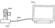
本発明の実施形態について図面を参照して以下に説明する。ソース機器とシンク機器とのHDMI接続例を図1に示す。デジタルテレビ100がシンク機器であり、デジタルビデオカメラ200がソース機器である。デジタルテレビ100、デジタルビデオカメラ200はそれぞれ本発明に係るHDMI機器の例である。 Embodiments of the present invention will be described below with reference to the drawings. An example of HDMI connection between the source device and the sink device is shown in FIG. The
デジタルテレビ100は、電源クレードル300を介して、デジタルビデオカメラ200とHDMIケーブル400で接続されている。HDMIケーブル400の一端は、デジタルテレビ100に設けられているHDMI端子に接続される。また、HDMIケーブル400の他端は、電源クレードル300に設けられているHDMI端子に接続される。そして、デジタルビデオカメラ200が電源クレードル300に載置されると、デジタルビデオカメラ200のコネクタと電源クレードル300のコネクタが接続され、デジタルテレビ100のHDMI入力部3(図2参照)とデジタルビデオカメラ200のHDMI出力部37(図3参照)とがHDMIケーブル400及び電源クレードル300を介して接続される。 The
次に、デジタルテレビ100の概略構成例を図2に示す。デジタルテレビ100は、チューナ2と、HDMI入力部3と、AV入力部4と、DEMUX(デマルチプレクサ)5と、AVデコーダ6と、リモコン受光部8と、スイッチ9と、映像処理部10と、OSD/スケーラ11と、映像出力部12と、音声処理部13と、音声出力部14と、スピーカ15と、第1のCPU(Central Processing Unit)16と、第2のCPU17と、メモリ18と、表示部19と、ホットプラグ制御部20とを備える。 Next, a schematic configuration example of the
アンテナ1は、屋外に配置されており、デジタル放送波を受信し、高周波デジタル変調信号をチューナ2に出力する。 The antenna 1 is disposed outdoors, receives a digital broadcast wave, and outputs a high-frequency digital modulation signal to the tuner 2.
チューナ2は、第1のCPU16からのチャンネル選択信号によって物理チャンネルを選択する。チューナ2は、このチャンネル選択プロセスによって、高周波デジタル変調信号を特定周波数の信号に変換する。また、チューナ2は、選択されたデジタル変調信号を復調してトランスポートストリームを生成し、その生成したトランスポートストリームをDEMUX5に出力する。 The tuner 2 selects a physical channel by a channel selection signal from the
DEMUX5は、チューナ2から受け取ったトランスポートストリームを、MPEG−2(Moving Picture Experts Group-2)のビデオストリーム、オーディオストリーム、およびPSI/SI(Program Specific Information/Service Information)等に分離する。 The DEMUX 5 separates the transport stream received from the tuner 2 into MPEG-2 (Moving Picture Experts Group-2) video stream, audio stream, PSI / SI (Program Specific Information / Service Information), and the like.
AVデコーダ6はビデオストリームに対してデコードを行うビデオデコーダ(不図示)と、オーディオストリームに対してデコードを行うオーディオデコーダ(不図示)とを備え、デコード後の映像音声情報をスイッチ9に出力する。 The
HDMI入力部3は、3つのHDMI端子(不図示)を有しており、各HDMI端子にHDMIケーブルが接続可能である。外部機器からHDMIケーブルのTMDSデータ信号線を介してHDMI入力部3に入力された映像音声情報は、スイッチ9に入力される。また、3つのHDMI端子のCECピンは直結されて第1のCPU16に接続されているため、外部機器(ソース機器)からHDMIケーブルのCEC信号線を介してHDMI入力部3に入力されたCECコマンドは、第1のCPU16に入力される。また、第1のCPU16からHDMI入力部3へ出力されたCECコマンドは、HDMIケーブルのCEC信号線を介して外部機器(ソース機器)に入力される。また、外部機器(ソース機器)からHDMIケーブルのDDC5V信号線、HDMI入力部3を介して5V電源がホットプラグ制御部20に供給される。NVRAM(不図示)がHDMI端子毎に個別に設けられ、その個別に設けられたNVRAMのうち、HDMIケーブルが接続されているHDMI端子に対応するNVRAMにのみ、外部機器(ソース機器)からHDMIケーブルのDDC5V信号線、HDMI入力部3を介して5V電源が供給される。ホットプラグ制御部20は、HDMI入力部3にLowレベル又はHighレベルの制御信号を出力することでソース機器からシンク機器へのAVデータの送出開始タイミングを指示する。 The HDMI input unit 3 has three HDMI terminals (not shown), and an HDMI cable can be connected to each HDMI terminal. Video / audio information input from the external device to the HDMI input unit 3 via the TMDS data signal line of the HDMI cable is input to the switch 9. Since the CEC pins of the three HDMI terminals are directly connected to the
また、AV入力部4は図示しないS端子、D端子、RCA端子を有し、外部機器からS端子ケーブルまたはD端子ケーブル及びRCA端子を介してAV入力部4に入力された映像音声情報はスイッチ9へ出力される。 The
スイッチ9は、AVデコーダ6、HDMI入力部3、AV入力部4の各映像音声入力を切り替えるスイッチである。映像処理部10は、スイッチ9を介して入力される映像情報に対してデジタル映像処理を行う。OSD/スケーラ11は、第2のCPU17から指示された文字情報や色情報に基づく映像データを生成したり、放送受信映像の縮小処理を行う回路である。このOSD/スケーラ11により、番組情報に基づくEPG(Electronic Program Guide)表示、データ放送表示、メニュー画面表示などが行える。映像出力部12は、ODS/スケーラ11から入力される映像情報を表示部19の入力信号形式に変換する。そして、表示部19は、映像出力部12から入力される映像信号に基づき映像を表示する。 The switch 9 is a switch for switching video / audio inputs of the
音声処理部13は、スイッチ9を介して音声情報を受け取り、D/A変換によるアナログ音声信号を音声出力部14に出力する。音声出力部14は、音声処理部13から入力された音声信号を増幅等しスピーカ15に出力する。そして、スピーカ15は、音声出力部14から入力された音声信号に基づき音声を発する。 The
リモコン送信機7は、デジタルテレビ100に指令を送出するための送信機である。このリモコン送信機7に設けられたキーが操作されると、そのキーに対応したリモコン信号がリモコン送信機7の発光部から送出される。リモコン受光部8は、リモコン信号を受光し、これを電気信号に変換して第1のCPU16に与える。 The remote control transmitter 7 is a transmitter for sending commands to the
第1のCPU16は、リモコン送信機7からのリモコン信号や図示しない操作部のキー操作による信号に対する処理、チューナ2などに対する制御を主に行う。そして、第1のCPU16は、リモコン送信機7による電源OFF(パワーセーブモードへの移行)が行われたときでも、電力供給を受けて動作しており、リモコン信号を監視する等の処理を行う。一方、第2のCPU17は、OSD/スケーラ11、映像処理部10、表示部19などに対する制御を主に行う。第1のCPU16と第2のCPU17とは、相互に通信ができる仕様となっており、第1のCPU16の制御により、第2のCPU17や映像・音声処理部21の各ブロックを停止/起動することが可能となっている。 The
メモリ18は、不揮発性メモリであって、制御プログラムや各種データを格納している。出力画像及び出力音声の画質及び音質に関連する信号処理の性能特性に関する情報並びに出力画像及び出力音声の画質及び音質に関連する信号処理の設定もメモリ18に格納されている。映像処理部10やOSD/スケーラ11は、メモリ18に格納されている出力画像の画質に関連する信号処理の設定に基づいて、映像信号の処理を実行し、音声処理部13や音声出力部14は、メモリ18に格納されている出力音声の音質に関連する信号処理の設定に基づいて、音声信号の処理を実行する。 The
次に、デジタルビデオカメラ200の概略構成例を図3に示す。デジタルビデオカメラ200は、レンズ31と、CCD(Charge Coupled Device)またはCMOS(Complimentary Metal Oxide Semiconductor)センサなどの撮像素子32と、A/D変換部33と、信号処理部34と、CPU35と、CEC用CPU36と、HDMI出力部37と、NTSC(National Television System Committee)エンコーダ38と、フラッシュメモリ39と、制御部40と、信号処理部41と、OSD部42と、LCD(Liquid Crystal Display)インタフェース43と、LCD44と、SDRAM(Synchronous Dynamic Random Access Memory)45と、JPEG(Joint Photographic Experts Group)コーディック部46と、MPEG−4コーディック部47と、USB(Universal Serial Bus)インタフェース48と、カードインタフェース49と、SDRAM50と、オーディオコーディック部51とを備える。信号処理部34、CPU35、フラッシュメモリ39、制御部40、信号処理部41、SDRAM45、JPEGコーディック部46、MPEG−4コーディック部47、USBインタフェース48、及びカードインタフェース49はそれぞれバスに接続されている。 Next, an example of a schematic configuration of the
デジタルビデオカメラ200は、レンズ31から入射される光を撮像素子32によって光電変換することによって、電気信号である映像データを取得する。撮像素子32で取得された映像データは、A/D変換部33によってアナログ信号からデジタル信号へと変換されたのち、信号処理部34に送られる。信号処理部34は、A/D変換部33から受け取った映像データに対して、YCbCrフォーマットへの変換、ホワイトバランス調整、レベル調整などの各種信号処理を施す。撮像素子32とA/D変換部33とは制御部40により制御される。但し、デジタルビデオカメラ200の全体的な制御はCPU35が行っており、制御部40もCPU35からの指令により制御の開始と停止を行う。 The
信号処理部34から出力される映像データは、動画撮影時の場合、MPEG−4コーディック部47に転送され、MPEG−4フォーマット形式に圧縮変換された後、カードインタフェース49を経由してSDカードに書き込まれ、静止画撮影時の場合、JPEGコーディック部46に転送され、圧縮変換された後、カードインタフェース49を経由してSDカードに書き込まれる。 The video data output from the
画像再生時においては、カードインタフェース49がSDカードから映像データを読み出す。その読み出された映像データは、動画データである場合MPEG−4コーディック部47によって復号処理され、静止画データである場合JPEGコーディック部46によって復号処理され、その後、信号処理部41によってスケーリング、画質調整、ノイズ除去などの各種信号処理が施され、OSD部42によってメニュー画面表示用の文字情報などが任意に付加され、LCDインタフェース43を経由してLCD44に出力される。また、OSD部42から出力される映像データは、NTSCエンコーダ38によってNTSC信号となり、S端子やRCA端子などの外部出力端子を経由して外部機器に外部出力される。また、OSD部42から出力される映像データは、HDMI出力部37によってTMDS形式の信号となり、HDMI端子を経由してシンク機器(本実施形態ではデジタルテレビ100)に外部出力される。 At the time of image reproduction, the card interface 49 reads video data from the SD card. The read video data is decoded by the MPEG-4
CEC用CPU36は、CPU35の制御に従って、CEC通信処理を行う。CEC用CPU36によって生成されたCECコマンドは、HDMI端子を経由してシンク機器(本実施形態ではデジタルテレビ100)に外部出力される。また、シンク機器(本実施形態ではデジタルテレビ100)から送信されたCECコマンドは、HDMI端子を経由してCEC用CPU36に入力され、CEC用CPU36によって処理される。 The
また、デジタルビデオカメラ200においては、マイクアンプやALC(Auto Level Control)を内蔵したオーディオコーディック部51が、内蔵マイクや外付けマイクから送られている音声信号に対して、A/D変換処理、増幅処理、レベル調整処理、指向性処理などの各種信号処理を施す。オーディオコーディック部51から出力される音声データは、MPEG−4コーディック部47によってAAC(Advanced Audio Coding)フォーマット形式に圧縮変換された後、カードインタフェース49を経由してSDカードに書き込まれる。 Further, in the
音声再生時においては、カードインタフェース49がSDカードから音声データを読み出す。その読み出された音声データは、MPEG−4コーディック部47によって復号処理され、スピーカアンプを内蔵したオーディオコーディック部51によってD/A変換されたのち、内蔵スピーカや外付けスピーカに出力される。また、オーディオコーディック部51は、復号された音声データをHDMI出力部37へ出力する。 At the time of audio reproduction, the card interface 49 reads audio data from the SD card. The read audio data is decoded by the MPEG-4
デジタルビデオカメラ200は、制御プログラムや各種データを格納している不揮発性メモリ(不図示)も備えている。出力画像及び出力音声の画質及び音質に関連する信号処理の性能特性に関する情報並びに出力画像及び出力音声の画質及び音質に関連する信号処理の設定も前記不揮発性メモリに格納されている。信号処理部41やOSD部42は、前記不揮発性メモリに格納されている出力画像の画質に関連する信号処理の設定に基づいて、映像信号の処理を実行し、オーディオコーディック部51は、前記不揮発性メモリに格納されている出力音声の音質に関連する信号処理の設定に基づいて、音声信号の処理を実行する。 The
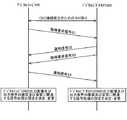
次に、デジタルテレビ100及びデジタルビデオカメラ200の双方において、出力画像及び出力音声の画質及び音質に関連する信号処理の設定を変更する例について図4を参照して以下に説明する。 Next, an example in which both the
HDMIインタフェースを利用してデジタルテレビ100とデジタルビデオカメラ200とでAVシステムを構築する場合、まず、デジタルビデオカメラ200を電源クレードル300に載置し、HDMIケーブル400の一端をデジタルテレビ100に設けられているHDMI端子に接続し、HDMIケーブル400の他端を電源クレードル300に設けられているHDMI端子に接続する。これにより、デジタルテレビ100とデジタルビデオカメラ200とがHDMI接続される。 When an AV system is constructed with the
続いて、デジタルビデオカメラ200とデジタルテレビ100との間で、CEC接続確立のためのやり取りが行われる。CEC接続確立のためのやり取りとしては、HPDやHDCPの認証などがある。但し、HDCPの認証はソース機器の種類によって行われないこともある。 Subsequently, exchange for establishing a CEC connection is performed between the
その後、デジタルテレビ100は、デジタルビデオカメラ200に対して、デジタルビデオカメラ200の出力画像及び出力音声の画質及び音質に関連する信号処理の性能特性情報を要求する取得要求信号S1を送信する。取得要求信号S1は、ベンダーが独自に定義したCECコマンド(ベンダーコマンド)であって、例えば、以下の表1のようなフォーマットにすればよい。 Thereafter, the

1バイト目のAddressは、デジタルテレビ100(論理Address0)からデジタルビデオカメラ200(論理Address4)への通信であることを示している。通信方向によりAddressは変化する。デジタルビデオカメラ200(論理Address4)からデジタルテレビ100(論理Address0)への通信である場合には、例えば、後述する表2のように1バイト目のAddressを0x40にすればよい。2バイト目のOP_Codeは、コマンドがベンダーの独自コードであることを示している。3バイト目は、コマンドが接続相手機器への機能問い合わせ(接続相手機器の出力画像及び出力音声の画質及び音質に関連する信号処理の性能特性の取得要求)であることを示している。 Address of the first byte indicates communication from the digital television 100 (logical address 0) to the digital video camera 200 (logical address 4). Address changes depending on the communication direction. In the case of communication from the digital video camera 200 (logical address 4) to the digital television 100 (logical address 0), for example, the first byte address may be set to 0x40 as shown in Table 2 described later. The OP_Code in the second byte indicates that the command is a vendor unique code. The third byte indicates that the command is a function inquiry to the connection partner device (request for obtaining performance characteristics of signal processing related to the image quality and sound quality of the output image and output sound of the connection partner device).
デジタルビデオカメラ200は、取得要求信号S1に対応して、デジタルビデオカメラ200の出力画像及び出力音声の画質及び音質に関連する信号処理の性能特性情報を通知する通知信号S2を、デジタルテレビ100に送信する。通知信号S2は、ベンダーが独自に定義したCECコマンド(ベンダーコマンド)であって、例えば、以下の表2のようなフォーマットにすればよい。 In response to the acquisition request signal S1, the
1バイト目のAddressは、デジタルビデオカメラ200(論理Address4)からデジタルテレビ100(論理Address0)への通信であることを示している。2バイト目のOP_Codeは、コマンドがベンダーの独自コードであることを示している。3バイト目は、機能通知(自己の出力画像及び出力音声の画質及び音質に関連する信号処理の性能特性通知)であることを示している。4バイト目は、映像、音声の信号処理分類の送信数を示している。5バイト目以降は、2バイト単位で機能番号(映像、音声の信号処理分類)とその機能番号における性能特性を表す数値とを示している。 Address of the first byte indicates communication from the digital video camera 200 (logical address 4) to the digital television 100 (logical address 0). The OP_Code in the second byte indicates that the command is a vendor unique code. The third byte indicates a function notification (image quality of own output image and output sound and signal processing performance characteristic related to sound quality). The fourth byte indicates the number of transmissions of the video and audio signal processing classification. The fifth and subsequent bytes indicate function numbers (video and audio signal processing classifications) and numerical values representing performance characteristics in the function numbers in units of 2 bytes.
なお、映像、音声の信号処理分類の例は以下の通りである。映像の信号処理であれば、バックライトの明るさ(液晶モニタの場合)、コントラスト、ブライトネス、色の濃さ、シャープネス、ノイズリダクション、色温度、肌色補正、シネマオート、ダイナミックAI(ダイナミック・オート・イメージ・コントロール)、ガンマ補正、出力解像度などに分類することができる。また、音声の信号処理であれば、高音、低音、3Dサラウンド、FOUCUS、ウーハーレベルなどに分類することができる。 Examples of video and audio signal processing classification are as follows. For video signal processing, backlight brightness (for LCD monitors), contrast, brightness, color saturation, sharpness, noise reduction, color temperature, skin color correction, cinema auto, dynamic AI (dynamic auto Image control), gamma correction, output resolution, etc. Further, in the case of audio signal processing, it can be classified into treble, bass, 3D surround, FOUCUS, woofer level, and the like.
デジタルビデオカメラ200は、通知信号S2の送信後、デジタルテレビ100に対して、デジタルテレビ100の出力画像及び出力音声の画質及び音質に関連する信号処理の性能特性情報を要求する取得要求信号S3を送信する。取得要求信号S3は、ベンダーが独自に定義したCECコマンド(ベンダーコマンド)であって、取得要求信号S1と同様のフォーマットにすればよい。 After transmitting the notification signal S2, the
デジタルテレビ100は、取得要求信号S3に対応して、デジタルテレビ100の出力画像及び出力音声の画質及び音質に関連する信号処理の性能特性情報を通知する通知信号S4を、デジタルビデオカメラ200に送信する。通知信号S4は、ベンダーが独自に定義したCECコマンド(ベンダーコマンド)であって、通知信号S2と同様のフォーマットにすればよい。 In response to the acquisition request signal S3, the
デジタルテレビ100は、メモリ18に格納されている自己の出力画像及び出力音声の画質及び音質に関連する信号処理の性能特性に関する情報とデジタルビデオカメラ200から送られてきた通知信号S2とに基づいて、自己の出力画像及び出力音声の画質及び音質に関連する信号処理の設定を決定し、その決定した設定に変更する。また、デジタルビデオカメラ200は、内部の不揮発性メモリに格納されている自己の出力画像及び出力音声の画質及び音質に関連する信号処理の性能特性に関する情報とデジタルテレビ100から送られてきた通知信号S4とに基づいて、自己の出力画像及び出力音声の画質及び音質に関連する信号処理の設定を決定し、その決定した設定に変更する。映像、音声の信号処理の種類により上記の決定方法は異なるが、例えば、ノイズフィルタによる信号処理の場合は、デジタルテレビ100のノイズフィルタとデジタルビデオカメラ200のノイズフィルタのうち性能の良い方のみが有効になるように、デジタルテレビ100、デジタルビデオカメラ200がそれぞれ自己の出力画像及び出力音声の画質及び音質に関連する信号処理の設定を決定すればよい。 The
なお、上記の方法で決定した設定をメモリに一時的に記憶しておいてHDMI接続が解除されると元の設定に戻すようにするか、又は、上記の方法で決定した設定をメモリに不揮発的に記憶しておいてHDMI接続が解除されると元の設定に戻しそれ以後対象機器がHDMI接続されている場合のみ上記の方法で決定した設定をメモリから読み出してその読み出した設定に変更するようにすることが望ましい。 Note that the setting determined by the above method is temporarily stored in the memory and restored to the original setting when the HDMI connection is released, or the setting determined by the above method is stored in the memory in a nonvolatile manner. When the HDMI connection is released, the original setting is restored and the setting determined by the above method is read from the memory and changed to the read setting only when the target device is HDMI connected thereafter. It is desirable to do so.
また、図4に示す手順の説明は、デジタルテレビ100とデジタルビデオカメラ200の双方が、上述した取得要求信号及び通知信号の送受信に対応している場合である。一方、例えば、デジタルテレビ100は上述した取得要求信号及び通知信号の送受信に対応しているがデジタルビデオカメラ200は上述した取得要求信号及び通知信号の送受信に対応していない場合、デジタルテレビ100は、取得要求信号S1を送信したにもかかわらずデジタルビデオカメラ200から通知信号S2が送られてこないことにより、デジタルビデオカメラ200が上述した取得要求信号及び通知信号の送受信に対応していないことを認識することができる。 4 is a case where both the
また、図4に示す手順の説明では、デジタルテレビ100とデジタルビデオカメラ200の双方がそれぞれ、送られてきた通知信号を基に、自己の出力画像及び出力音声の画質及び音質に関連する信号処理の設定を決定していたが、デジタルテレビ100とデジタルビデオカメラ200の片方のみが、送られてきた通知信号を基に、自己の出力画像及び出力音声の画質及び音質に関連する信号処理の設定を決定するようにしてもよい。例えば、デジタルテレビ100とデジタルビデオカメラ200の片方のみが、送られてきた通知信号を基に、自己の出力画像及び出力音声の画質及び音質に関連する信号処理の設定を決定するようにする場合、取得要求信号S3及び通知信号S4の送受信を行わないようにし、デジタルテレビ100が、メモリ18に格納されている自己の出力画像及び出力音声の画質及び音質に関連する信号処理の性能特性に関する情報と通知信号S2とに基づいて、自己の出力画像及び出力音声の画質及び音質に関連する信号処理の設定及び接続相手機器(デジタルビデオカメラ200)の出力画像及び出力音声の画質及び音質に関連する信号処理の設定を決定し、決定した接続相手機器(デジタルビデオカメラ200)の出力画像及び出力音声の画質及び音質に関連する信号処理の設定を、ベンダーが独自に定義したCECコマンド(ベンダーコマンド)で接続相手機器(デジタルビデオカメラ200)に通知するようにすることができる。 In the description of the procedure shown in FIG. 4, both the
以上、本発明に係る実施形態について説明したが、本発明の範囲はこれに限定されるものではなく、発明の主旨を逸脱しない範囲で種々の変更を加えて実行することができる。例えば、デジタルビデオカメラ200にHDMI端子を設け、デジタルテレビ100とデジタルビデオカメラ200とが電源クレードル300を介さずにHDMIケーブル400で接続されるようにしてもよい。 As mentioned above, although embodiment which concerns on this invention was described, the range of this invention is not limited to this, A various change can be added and implemented in the range which does not deviate from the main point of invention. For example, the
100 デジタルテレビ
200 デジタルビデオカメラ
300 電源クレードル
400 HDMIケーブル
1 アンテナ
2 チューナ
3 HDMI入力部
4 AV入力部
5 DEMUX(デマルチプレクサ)
6 AVデコーダ
7 リモコン送信機
8 リモコン受光部
9 スイッチ
10 映像処理部
11 OSD/スケーラ
12 映像出力部
13 音声処理部
14 音声出力部
15 スピーカ
16 第1のCPU
17 第2のCPU
18 メモリ
19 表示部
20 ホットプラグ制御部
21 映像・音声処理部
31 レンズ
32 撮像素子
33 A/D変換部
34 信号処理部
35 CPU
36 CEC用CPU
37 HDMI出力部
38 NTSCエンコーダ
39 フラッシュメモリ
40 制御部
41 信号処理部
42 OSD部
43 LCDインタフェース
44 LCD
45 SDRAM
46 JPEGコーディック部
47 MPEG−4コーディック部
48 USBインタフェース
49 カードインタフェース
50 SDRAM
51 オーディオコーディック部DESCRIPTION OF
6 AV decoder 7 Remote control transmitter 8 Remote control light receiving unit 9
17 Second CPU
36 CPU for CEC
37
45 SDRAM
46
51 Audio codec club
Claims (3)
Translated fromJapanese前記HDMI機器の出力画像及び出力音声の画質及び音質に関連する信号処理の性能特性に関する情報を記憶する記憶部と、
前記接続相手機器の出力画像及び出力音声の画質及び音質に関連する信号処理の性能特性に関する情報をCECコマンド受信により前記接続相手機器から取得する情報取得部と、
前記記憶部が記憶している前記HDMI機器の出力画像及び出力音声の画質及び音質に関連する信号処理の性能特性に関する情報と、前記情報取得部が取得した前記接続相手機器の出力画像及び出力音声の画質及び音質に関連する信号処理の性能特性に関する情報とに基づいて、前記HDMI機器の出力画像及び出力音声の画質及び音質に関連する信号処理の設定を決定し、その決定した設定に変更する設定変更部とを備えることを特徴とするHDMI機器。An HDMI device that is HDMI-connected to a connection partner device and constitutes an AV system together with the connection partner device,
A storage unit that stores information on performance characteristics of signal processing related to image quality and sound quality of an output image and output sound of the HDMI device;
An information acquisition unit that acquires information about the performance characteristics of signal processing related to the image quality and sound quality of the output image and output sound of the connection counterpart device from the connection counterpart device by receiving a CEC command;
Information on the output image and output sound quality of the HDMI device stored in the storage unit and information on signal processing performance characteristics related to the sound quality, and the output image and output sound of the connection partner device acquired by the information acquisition unit The signal processing setting related to the image quality and sound quality of the output image and output sound of the HDMI device is determined based on the information related to the performance characteristics of the signal processing related to the image quality and sound quality of the device, and changed to the determined setting. An HDMI device comprising a setting change unit.
前記設定変更部によって決定された前記接続相手機器の出力画像及び出力音声の画質及び音質に関連する信号処理の設定をCECコマンド送信により前記接続相手機器に通知する設定通知部を備えることを特徴とする請求項1又は請求項2に記載のHDMI機器。The setting change unit stores information related to performance characteristics of signal processing related to the image quality and sound quality of the output image and output audio of the HDMI device stored in the storage unit, and the connection partner device acquired by the information acquisition unit Based on the output image and the information on the performance characteristics of the signal processing related to the image quality and sound quality of the output sound, and also determines the setting of the signal processing related to the image quality and sound quality of the output image and output sound of the connection partner device,
A setting notification unit for notifying the connection partner device of the output image and output sound quality of the connection partner device determined by the setting change unit and signal processing settings related to the sound quality by transmitting a CEC command; The HDMI device according to claim 1 or 2.
Priority Applications (2)
| Application Number | Priority Date | Filing Date | Title |
|---|---|---|---|
| JP2009036269AJP2010193247A (en) | 2009-02-19 | 2009-02-19 | Hdmi apparatus |
| US12/708,796US20100214480A1 (en) | 2009-02-19 | 2010-02-19 | HDMI Device and Electronic Device |
Applications Claiming Priority (1)
| Application Number | Priority Date | Filing Date | Title |
|---|---|---|---|
| JP2009036269AJP2010193247A (en) | 2009-02-19 | 2009-02-19 | Hdmi apparatus |
Publications (1)
| Publication Number | Publication Date |
|---|---|
| JP2010193247Atrue JP2010193247A (en) | 2010-09-02 |
Family
ID=42630664
Family Applications (1)
| Application Number | Title | Priority Date | Filing Date |
|---|---|---|---|
| JP2009036269APendingJP2010193247A (en) | 2009-02-19 | 2009-02-19 | Hdmi apparatus |
Country Status (2)
| Country | Link |
|---|---|
| US (1) | US20100214480A1 (en) |
| JP (1) | JP2010193247A (en) |
Cited By (3)
| Publication number | Priority date | Publication date | Assignee | Title |
|---|---|---|---|---|
| US8984181B2 (en) | 2012-06-11 | 2015-03-17 | Kabushiki Kaisha Toshiba | Video sender and video receiver |
| JP2015177474A (en)* | 2014-03-17 | 2015-10-05 | 株式会社リコー | Terminal, method and program |
| US9635303B2 (en) | 2011-10-20 | 2017-04-25 | Kabushiki Kaisha Toshiba | Communication device and communication method |
Families Citing this family (7)
| Publication number | Priority date | Publication date | Assignee | Title |
|---|---|---|---|---|
| JP4376931B2 (en)* | 2007-10-31 | 2009-12-02 | 株式会社東芝 | Display device and display method |
| JP5444797B2 (en)* | 2009-04-10 | 2014-03-19 | ソニー株式会社 | Transmission device, display device, and image display system |
| EP2785053B1 (en)* | 2011-11-25 | 2020-12-02 | Panasonic Corporation | Transmission device and reception device for baseband video data, and transmission/reception system |
| CN102724467B (en) | 2012-05-18 | 2016-06-29 | 中兴通讯股份有限公司 | Promote method and the terminal unit of video frequency output definition |
| EP3005679B1 (en)* | 2013-05-31 | 2020-01-08 | Canon Kabushiki Kaisha | Image pickup system, image pickup apparatus, and method of controlling the same |
| US10319336B2 (en)* | 2016-02-16 | 2019-06-11 | Samsung Electronics Co., Ltd. | Electronic device and control method thereof |
| JP7003079B2 (en) | 2019-03-14 | 2022-01-20 | 株式会社東芝 | Electronics |
Family Cites Families (36)
| Publication number | Priority date | Publication date | Assignee | Title |
|---|---|---|---|---|
| JP4441945B2 (en)* | 1999-05-07 | 2010-03-31 | ソニー株式会社 | Control method and control apparatus |
| JP4312934B2 (en)* | 1999-06-29 | 2009-08-12 | エルジー エレクトロニクス インコーポレイティド | Operation method based on characteristic information between devices connected through digital interface and control device thereof |
| US6262763B1 (en)* | 1999-07-01 | 2001-07-17 | Sony Corporation | Actual size image display |
| JP4192371B2 (en)* | 1999-12-09 | 2008-12-10 | ソニー株式会社 | Data receiving apparatus, data transmitting apparatus, and data transmitting / receiving system |
| GB0000874D0 (en)* | 2000-01-14 | 2000-03-08 | Koninkl Philips Electronics Nv | Latency handling for interconnected devices |
| KR100327377B1 (en)* | 2000-03-06 | 2002-03-06 | 구자홍 | Method of Displaying Digital Broadcasting signals Using Digital Broadcasting Receiver and Digital Display Apparatus |
| US7224404B2 (en)* | 2001-07-30 | 2007-05-29 | Samsung Electronics Co., Ltd. | Remote display control of video/graphics data |
| KR100412503B1 (en)* | 2001-12-13 | 2003-12-31 | 삼성전자주식회사 | SetTop Box capable of setting easily resolution of digital broadcast signal |
| TWI220367B (en)* | 2003-09-02 | 2004-08-11 | Avermedia Tech Inc | Video signal processing apparatus and computer system with the same |
| JP2005109703A (en)* | 2003-09-29 | 2005-04-21 | Pioneer Electronic Corp | Apparatus and method for outputting image, image display system, image output program and information recording medium |
| MXPA06005230A (en)* | 2003-11-10 | 2007-03-12 | Thomson Licensing | Method and apparatus for providing simplified peer-to-peer recording. |
| JP2005333472A (en)* | 2004-05-20 | 2005-12-02 | Toshiba Corp | Video signal receiving apparatus and video signal receiving method |
| JP4468142B2 (en)* | 2004-10-29 | 2010-05-26 | 株式会社東芝 | Data relay device, data relay method, and data transmission system |
| US7893998B2 (en)* | 2005-07-29 | 2011-02-22 | Hewlett-Packard Development Company, L.P. | Audio over a standard video cable |
| EP1995952A4 (en)* | 2006-03-03 | 2010-05-19 | Panasonic Corp | TRANSMITTER DEVICE, RECEIVER DEVICE, AND TRANSCEIVER / RECEIVER DEVICE |
| JP3952077B1 (en)* | 2006-06-06 | 2007-08-01 | オンキヨー株式会社 | Hot plug signal detection device, source device and repeater device |
| WO2008069304A1 (en)* | 2006-12-08 | 2008-06-12 | Panasonic Corporation | Remote control system |
| JP5086632B2 (en)* | 2006-12-22 | 2012-11-28 | 株式会社東芝 | Video display device, video display system, and video display method |
| JP5142554B2 (en)* | 2007-02-26 | 2013-02-13 | キヤノン株式会社 | RECORDING CONTROL DEVICE AND RECORDING CONTROL DEVICE CONTROL METHOD |
| US7767544B2 (en)* | 2007-04-12 | 2010-08-03 | Micron Technology Inc. | Semiconductor fabrication method and system |
| JP5091578B2 (en)* | 2007-07-26 | 2012-12-05 | 株式会社東芝 | Video processing apparatus and video processing method |
| US7817586B2 (en)* | 2007-08-16 | 2010-10-19 | Mediatek Inc. | High-speed digital interface transceiver and method of supplying bi-directional communication process on high-speed digital interface device |
| KR101464661B1 (en)* | 2007-08-17 | 2014-11-25 | 삼성전자주식회사 | VIDEO EQUIPMENT WITH A VIDEO OUTPUT MODE CHANGE FUNCTION FOR EXTERNAL-VIDEO EQUIPMENT |
| US9110624B2 (en)* | 2007-09-21 | 2015-08-18 | Nvdia Corporation | Output restoration with input selection |
| JP4479776B2 (en)* | 2007-10-05 | 2010-06-09 | ソニー株式会社 | Display device and transmission device |
| JP5339573B2 (en)* | 2007-11-15 | 2013-11-13 | ソニー エスパナ,エス.エー. | Display device, program information display method in display device, receiving device, and signal transmission method in receiving device |
| JP5050807B2 (en)* | 2007-11-22 | 2012-10-17 | ソニー株式会社 | REPRODUCTION DEVICE, DISPLAY DEVICE, REPRODUCTION METHOD, AND DISPLAY METHOD |
| JP2009141720A (en)* | 2007-12-07 | 2009-06-25 | Hitachi Ltd | Video display device, display panel, and video processing device |
| JP4535161B2 (en)* | 2008-04-01 | 2010-09-01 | ソニー株式会社 | Electronic device, communication system, communication method, and program |
| US8253860B2 (en)* | 2008-04-07 | 2012-08-28 | Mediatek Inc. | System, method and devices for HDMI transmission using a commonly supported media format |
| JP4435251B2 (en)* | 2008-08-29 | 2010-03-17 | 株式会社東芝 | VIDEO DISPLAY DEVICE, VIDEO REPRODUCTION DEVICE, VIDEO DISPLAY METHOD, AND VIDEO REPRODUCTION METHOD |
| EP2187382A3 (en)* | 2008-11-05 | 2010-12-15 | Samsung Electronics Co., Ltd. | Video apparatus and method of controlling the video apparatus |
| US8286210B2 (en)* | 2008-11-13 | 2012-10-09 | Sony Corporation | HDMI switching technology for the coupling of consumer electronic control and/or non-consumer electronic control devices in an audio/visual environment |
| US20100216508A1 (en)* | 2009-02-23 | 2010-08-26 | Augusta Technology, Inc. | Systems and Methods for Driving an External Display Device Using a Mobile Phone Device |
| US8606896B2 (en)* | 2009-10-08 | 2013-12-10 | Sony Corporation | Home network component controlling data and function of another home network component |
| US8411208B2 (en)* | 2009-12-29 | 2013-04-02 | VIZIO Inc. | Attached device control on television event |
- 2009
- 2009-02-19JPJP2009036269Apatent/JP2010193247A/enactivePending
- 2010
- 2010-02-19USUS12/708,796patent/US20100214480A1/ennot_activeAbandoned
Cited By (8)
| Publication number | Priority date | Publication date | Assignee | Title |
|---|---|---|---|---|
| US9635303B2 (en) | 2011-10-20 | 2017-04-25 | Kabushiki Kaisha Toshiba | Communication device and communication method |
| US9706151B2 (en) | 2011-10-20 | 2017-07-11 | Kabushiki Kaisha Toshiba | Communication device and communication method |
| US10873717B2 (en) | 2011-10-20 | 2020-12-22 | Kabushiki Kaisha Toshiba | Communication device and communication method |
| US11297277B2 (en) | 2011-10-20 | 2022-04-05 | Kabushiki Kaisha Toshiba | Communication device and communication method |
| US8984181B2 (en) | 2012-06-11 | 2015-03-17 | Kabushiki Kaisha Toshiba | Video sender and video receiver |
| US9357192B2 (en) | 2012-06-11 | 2016-05-31 | Kabushiki Kaisha Toshiba | Video sender and video receiver |
| US10341726B2 (en) | 2012-06-11 | 2019-07-02 | Toshiba Visual Solutions Corporation | Video sender and video receiver |
| JP2015177474A (en)* | 2014-03-17 | 2015-10-05 | 株式会社リコー | Terminal, method and program |
Also Published As
| Publication number | Publication date |
|---|---|
| US20100214480A1 (en) | 2010-08-26 |
Similar Documents
| Publication | Publication Date | Title |
|---|---|---|
| US8269899B2 (en) | Electronic device, method for responding to message, and program | |
| JP2010193247A (en) | Hdmi apparatus | |
| US8903523B2 (en) | Audio processing device, audio processing method, and program | |
| JP6702455B2 (en) | Display device, display control method, and computer program | |
| US8713598B2 (en) | Electronic device and control method therein | |
| US8281045B2 (en) | Device control device, device control method, and computer program | |
| US8869214B2 (en) | Device control apparatus, device control method and computer program | |
| JP2004357029A (en) | Signal selection device and signal selection method | |
| US8717503B2 (en) | Audio output device connectable with plurality of devices and method of controlling the same | |
| US20090219441A1 (en) | Information processing apparatus | |
| JP2012147425A (en) | Electronic apparatus and program | |
| US8643727B2 (en) | Electronic device related to automatic time setting | |
| JP6307856B2 (en) | Transmitting device, wide color gamut image data transmitting method, receiving device, wide color gamut image data receiving method and program | |
| CN101601283B (en) | Image signal processing device for disassembling multiple modules and control method thereof | |
| JP5577789B2 (en) | Image data transmitting apparatus, image data transmitting method, and image data receiving apparatus | |
| JP5171428B2 (en) | Electronics | |
| JP6535560B2 (en) | Electronic device and display method | |
| JP2010004289A (en) | Display device | |
| US9420218B2 (en) | Television system | |
| KR20100050373A (en) | Video apparatus and method for controlling video apparatus | |
| JP5205439B2 (en) | Video display device | |
| KR100619700B1 (en) | Wireless TV's Micom Control Unit | |
| WO2013161562A1 (en) | Image processing apparatus | |
| JP2010166350A (en) | Electronic device | |
| JP2013198097A (en) | Electronic apparatus, method and program |